
4.5-INCH COMPACT
CIRCULAR SAW
Instruction Manual
IMPORTANT: Your new tool has been engineered and manufactured to WEN’s highest standards for dependability,
ease of operation, and operator safety. When properly cared for, this product will supply you years of rugged,
trouble-free performance. Pay close attention to the rules for safe operation, warnings, and cautions. If you use
your tool properly and for its intended purpose, you will enjoy years of safe, reliable service.
NEED HELP? CONTACT US!
Have product questions? Need technical support? Please feel free to contact us:
TECHSUPPOR[email protected]1-847-429-9263 (M-F 8AM-5PM CST)
For replacement parts and the most up-to-date instruction manuals, visit WENPRODUCTS.COM
MODEL 3625

CONTENTS
WELCOME 3
Introduction ..................................................................................................... 3
Specifications ................................................................................................... 3
SAFETY 4
General Safety Rules ........................................................................................ 4
Circular Saw Safety Warnings .......................................................................... 6
Electrical Information ....................................................................................... 9
BEFORE OPERATING 10
Unpacking & Packing List ...............................................................................10
Know Your Circular Saw................................................................................. 11
Assembly & Adjustments ............................................................................... 11
OPERATION & MAINTENANCE 15
Operation ....................................................................................................... 15
Maintenance ....................................................................................................17
Exploded View & Parts List .............................................................................19
Warranty Statement ........................................................................................22
To purchase accessories and replacement parts for your tool, visit WENPRODUCTS.COM
Replacement Wood-Cutting Blades (Model BL11510W)
2

Model Number 3625
Motor 120V AC, 60 Hz, 5A
Motor Speed (No-Load) 3500 RPM
Blade Diameter 4-1/2 in. (115mm)
Arbor Size 3/8 in. (10mm)
Maximum Cutting Depth
90º 1-11/16 in. (43mm)
45º 1-1/8 in. (28mm)
Blade Body Thickness 1.2mm
Blade Teeth Thickness 1.8mm
Laser Battery Type LR44
Laser Power 0.278 mW
Laser Class II, 650 nm
Dust Tube Outer Diameter 1.35 in. to 1.5 in.
Base Plate Dimensions 9.5 in. x 3.4 in. x 0.079 in.
Product Dimensions 16.2 in. x 4.3 in. x 4.3 in.
Product Weight 5.8 lbs
SPECIFICATIONS
INTRODUCTION
Thanks for purchasing the WEN Circular Saw. We know you are excited to put your tool to work, but first, please
take a moment to read through the manual. Safe operation of this tool requires that you read and understand this
operator’s manual and all the labels affixed to the tool. This manual provides information regarding potential safety
concerns, as well as helpful assembly and operating instructions for your tool.
NOTE: The following safety information is not meant to cover all possible conditions and situations that may occur.
WEN reserves the right to change this product and specifications at any time without prior notice.
At WEN, we are continuously improving our products. If you find that your tool does not exactly match this manual,
please visit wenproducts.com for the most up-to-date manual or contact our customer service at 1-847-429-9263.
Keep this manual available to all users during the entire life of the tool and review it frequently to maximize
safety for both yourself and others.
Indicates danger, warning, or caution. The safety symbols and the explanations with them deserve your
careful attention and understanding. Always follow the safety precautions to reduce the risk of fire, electric shock
or personal injury. However, please note that these instructions and warnings are not substitutes for proper ac-
cident prevention measures.
3

GENERAL SAFETY RULES
WORK AREA SAFETY
1. Keep work area clean and well lit. Cluttered or dark
areas invite accidents.
2. Do not operate power tools in explosive atmo-
spheres, such as in the presence of flammable liquids,
gases or dust. Power tools create sparks which may ig-
nite the dust or fumes.
3. Keep children and bystanders away while operating
a power tool. Distractions can cause you to lose control.
ELECTRICAL SAFETY
1. Power tool plugs must match the outlet. Never mod-
ify the plug in any way. Do not use any adapter plugs
with earthed (grounded) power tools. Unmodified plugs
and matching outlets will reduce risk of electric shock.
2. Avoid body contact with earthed or grounded surfac-
es such as pipes, radiators, ranges and refrigerators.
There is an increased risk of electric shock if your body
is earthed or grounded.
3. Do not expose power tools to rain or wet conditions.
Water entering a power tool will increase the risk of elec-
tric shock.
4. Do not abuse the cord. Never use the cord for car-
rying, pulling or unplugging the power tool. Keep cord
away from heat, oil, sharp edges or moving parts.
Damaged or entangled cords increase the risk of electric
shock.
5. When operating a power tool outdoors, use an ex-
tension cord suitable for outdoor use. Use of a cord
suitable for outdoor use reduces the risk of electric
shock.
6. If operating a power tool in a damp location is un-
avoidable, use a ground fault circuit interrupter (GFCI)
protected supply. Use of a GFCI reduces the risk of elec-
tric shock.
PERSONAL SAFETY
1. Stay alert, watch what you are doing and use com-
mon sense when operating a power tool. Do not use a
power tool while you are tired or under the influence
of drugs, alcohol or medication. A moment of inatten-
tion while operating power tools may result in serious
personal injury.
2. Use personal protective equipment. Always wear
eye protection. Protective equipment such as a respira-
tory mask, non-skid safety shoes and hearing protection
used for appropriate conditions will reduce the risk of
personal injury.
3. Prevent unintentional starting. Ensure the switch is
in the off-position before connecting to power source
and/or battery pack, picking up or carrying the tool.
Carrying power tools with your finger on the switch or
energizing power tools that have the switch on invites
accidents.
4. Remove any adjusting key or wrench before turning
the power tool on. A wrench or a key left attached to a
rotating part of the power tool may result in personal
injury.
5. Do not overreach. Keep proper footing and balance
at all times. This enables better control of the power
tool in unexpected situations.
6. Dress properly. Do not wear loose clothing or jew-
elry. Keep your hair and clothing away from moving
parts. Loose clothes, jewelry or long hair can be caught
in moving parts.
Safety is a combination of common sense, staying alert and knowing how your item works. The term “power tool”
in the warnings refers to your mains-operated (corded) power tool or battery-operated (cordless) power tool.
SAVE THESE SAFETY INSTRUCTIONS.
WARNING! Read all safety warnings and all instructions. Failure to follow the warnings and instructions may
result in electric shock, fire and/or serious injury.
4

GENERAL SAFETY RULES
7. If devices are provided for the connection of dust
extraction and collection facilities, ensure these are
connected and properly used. Use of dust collection
can reduce dust-related hazards.
POWER TOOL USE AND CARE
1. Do not force the power tool. Use the correct power
tool for your application. The correct power tool will
do the job better and safer at the rate for which it was
designed.
2. Do not use the power tool if the switch does not turn
it on and off. Any power tool that cannot be controlled
with the switch is dangerous and must be repaired.
3. Disconnect the plug from the power source and/or
the battery pack from the power tool before making
any adjustments, changing accessories, or storing
power tools. Such preventive safety measures reduce
the risk of starting the power tool accidentally.
4. Store idle power tools out of the reach of children
and do not allow persons unfamiliar with the power
tool or these instructions to operate the power tool.
Power tools are dangerous in the hands of untrained us-
ers.
5. Maintain power tools. Check for misalignment or
binding of moving parts, breakage of parts and any
other condition that may affect the power tool’s opera-
tion. If damaged, have the power tool repaired before
use. Many accidents are caused by poorly maintained
power tools.
6. Keep cutting tools sharp and clean. Properly main-
tained cutting tools with sharp cutting edges are less
likely to bind and are easier to control.
7. Use the power tool, accessories and tool bits, etc.
in accordance with these instructions, taking into ac-
count the working conditions and the work to be per-
formed. Use of the power tool for operations different
from those intended could result in a hazardous situa-
tion.
8. Use clamps to secure your workpiece to a stable
surface. Holding a workpiece by hand or using your
body to support it may lead to loss of control.
9. KEEP GUARDS IN PLACE and in working order.
SERVICE
1. Have your power tool serviced by a qualified repair
person using only identical replacement parts. This
will ensure that the safety of the power tool is main-
tained.
CALIFORNIA PROPOSITION 65 WARNING
Some dust created by power sanding, sawing, grinding,
drilling, and other construction activities may contain
chemicals, including lead, known to the State of Califor-
nia to cause cancer, birth defects, or other reproductive
harm. Wash hands after handling. Some examples of
these chemicals are:
• Lead from lead-based paints.
• Crystalline silica from bricks, cement, and other
masonry products.
• Arsenic and chromium from chemically treated
lumber.
Your risk from these exposures varies depending on
how often you do this type of work. To reduce your ex-
posure to these chemicals, work in a well-ventilated area
with approved safety equipment such as dust masks
specially designed to filter out microscopic particles.
Safety is a combination of common sense, staying alert and knowing how your item works. The term “power tool”
in the warnings refers to your mains-operated (corded) power tool or battery-operated (cordless) power tool.
SAVE THESE SAFETY INSTRUCTIONS.
WARNING! Read all safety warnings and all instructions. Failure to follow the warnings and instructions may
result in electric shock, fire and/or serious injury.
5

CIRCULAR SAW SAFETY WARNINGS
WARNING! Do not operate the power tool until you have read and understood the following instructions and
the warning labels.
CIRCULAR SAW SAFETY
1. TOOL PURPOSE. This circular saw is designed to cut
through softwood, tile, and aluminum only. Cutting other
materials could result in fire, injury, or damage to the
workpiece. Using the machine for any other purpose for
which it is not designed may result in serious injuries,
machine damage and voiding of the warranty.
2. Check the base plate for proper movement before
each use. Press the blade release button to make sure
the base plate can move freely and does not touch the
blade or any other parts. Do not operate the saw if the
base plate does not move or does not open and close
smoothly. Dropping the saw may cause the base plate to
not work properly.
3. PERSONAL SAFETY.
• Always wear ANSI Z87.1-approved glasses with side
shields, hearing protection and a dust mask.
• Do not wear loose clothing or jewelry, as they might get
drawn in by the tool. Tie back long hair.
• DO NOT wear gloves while operating this machine.
4. ELECTRIC CORDS. Keep cords away from heat, oil,
sharp edges, and moving parts of the tool. Have an elec-
trician replace or repair damaged or worn cords imme-
diately.
5. TOOL INSPECTION. Before operation, check the tool
for any damaged or missing parts. Do not use the tool
if any part is missing or damaged. Do not use the tool if
the power switch is faulty, the plug or cable is damaged,
or the tool produces sparks, smoke, or unpleasant odors
(you may smell brushes wearing down for a few minutes
as the tool breaks in during the first use, that is normal).
Make sure all adjustments are correct and all connec-
tions are tight.
6. SECURING THE WORKPIECE. Use clamps to secure
the workpiece whenever possible to prevent wobble,
damage to the workpiece, and personal injury. Never
hold a piece being cut in your hands or across your legs.
It is important to support the work properly to minimize
body exposure, blade binding, or loss of control.
7. STANDING POSITION. Keep your body positioned to
either side of the saw blade, but not in line with cutting
path. Kickback could cause the saw to jump backwards.
8. STARTING THE TOOL. Always start the saw before
the blade is in contact with the workpiece. Let the blade
reach full speed before using the tool. The reaction to the
torque as the motor accelerates to full speed may cause
the tool to kick back.
9. KEEP HANDS AWAY. Keep hands away from the cut-
ting area and the blade. Do not reach underneath the
workpiece. The blade guard cannot protect you from the
blade protruding from the underside of the workpiece.
Do not attempt to remove cut material when the blade
is moving.
10. DURING OPERATION. Do not apply excessive pres-
sure to the tool. Overstressing the tool may cause kick-
back and damage the tool and accessories. Use special
care when working corners, sharp edges etc.
6

These safety instructions can’t possibly warn of every scenario that may arise with this tool,
so always make sure to stay alert and use common sense during operation.
CIRCULAR SAW SAFETY WARNINGS
WARNING! Do not operate the power tool until you have read and understood the following instructions and
the warning labels.
CIRCULAR SAW SAFETY
11. TURNING OFF THE TOOL. The blade coasts after the
saw is turned off. Wait until the blade comes to a full
stop before reaching for loose materials or setting the
tool down.
12. REPLACING THE SAW BLADE. Check the blade for
chipped or broken teeth. Do not use dull or damaged
blades. Unshaped or improperly set blades produce nar-
row kerf, causing excessive friction, blade binding, and
kickback. Always use blades with correct size and arbor
holes. Blades that do not match the mounting hardware
of the saw will run eccentrically, causing a loss of con-
trol.
13. MAKING ADJUSTMENTS. Always turn off and un-
plug the saw before making adjustments or changing
attachments. Accidental start-ups may occur if the saw
is plugged in during an accessory change. Develop a pe-
riodic maintenance schedule for your tool. Always make
sure the power switch is in the OFF position and the ma-
chine is unplugged when doing any cleaning, assembly,
setup operations, or when not in use.
14. REPLACEMENTS. Should any component of your
saw be missing/damaged or fail in any way, shut off the
switch and remove the plug from power supply outlet.
Replace the missing, damaged, or failed parts using only
identical replacement parts before resuming operation.
REDUCING KICKBACK
Kickback is a sudden reaction to a pinched, bound or
misaligned saw blade, causing an uncontrolled saw to
lift up and out of the work piece toward the operator.
When the blade is pinched or bound tightly by the kerf
closing down, the blade stalls and the motor reaction
drives the unit rapidly back toward the operator. If the
blade becomes twisted or misaligned in the cut, the teeth
at the back edge of the blade can dig into the top surface
of the wood causing the blade to climb out of the kerf
and jump back towards the operator. Take the proper
precautions below to reduce the risk of kickback.
• Maintain a firm grip on the saw and position your body
and arm in a way that allows you to resist kickback forc-
es. Kickback forces can be controlled by the operator, if
proper precautions are taken.
• When a blade is binding (or when interrupting a cut for
any reason), release the trigger and hold the saw motion-
less in the material until the blade comes to a complete
stop. Never attempt to remove the saw from the work
or pull the saw backward while the blade is in motion or
kickback may occur.
• When restarting a saw in the workpiece, center the
blade in the kerf and check that the teeth are not en-
gaged into the material. If the saw blade is binding, it
may walk up or kickback from the work piece as the saw
is restarted. Investigate and take corrective actions to
eliminate the causes of blade binding.
• Support large workpieces to minimize the risk of blade
pinching and kickback. Large panels and boards tend to
sag under their own weight. Supports must be placed
under the panel or board on both sides, near the edge of
the panel or board.
• Do not use dull or damaged blades. Unshaped or im-
properly set blades produce narrow kerf, causing exces-
sive friction, blade binding, and kickback.
• Blade depth and bevel adjusting locking levers must
be tight and secure before making a cut. If the blade ad-
justment shifts while cutting, it will cause binding and
kickback.
7

CIRCULAR SAW SAFETY WARNINGS
WARNING! Do not operate the power tool until you have read and understood the following instructions and
the warning labels.
LASER SAFETY
ATTENTION! LASER RADIATION. CLASS 2 LASER. DO
NOT STARE INTO THE BEAM.
1. Do not look directly into the laser beam with unpro-
tected eyes. Never look into the path of the beam.
2. Never point the laser beam towards reflective sur-
faces. Never point the laser towards people or animals.
Even a laser beam with a low output can cause damage
to the eyes.
3. Never open the laser module as unexpected exposure
to the beam can occur. The laser cannot be replaced with
a different type of laser.
4. Repairs of the laser may only be carried out by the
laser manufacturer or an authorized representative.
BATTERY SAFETY
1. Do not short-circuit batteries. Keep the batteries away
from metal objects when not in use.
2. Do not charge non-rechargeable batteries.
3. Do not mix old and new batteries or batteries of differ-
ent types. Replace an entire set of batteries at the same
time.
4. Do not keep batteries near fire, ovens or other sources
of heat. Do not use batteries in direct sunlight.
5. Remove batteries from the equipment when it will not
be used for an extended period of time.
6. Never handle batteries that have leaked without ap-
propriate protection. If the leaked fluid comes into con-
tact with your skin, the skin in this area should be rinsed
off under running water immediately. Always prevent the
fluid from coming into contact with the eyes and mouth.
In the event of contact, please seek immediate medical
attention.
7. Do not dismantle batteries. Dispose of used batteries
properly at your local collection/recycling facility.
8

ELECTRICAL INFORMATION
AMPERAGE
REQUIRED GAUGE FOR EXTENSION CORDS
25 ft. 50 ft. 100 ft. 150 ft.
5A 18 gauge 16 gauge 16 gauge 14 gauge
IMPORTANT: Servicing a double-insulated product requires extreme care and knowledge of the system, and
should be done only by qualified service personnel using identical replacement parts. Always use original factory
replacement parts when servicing.
1. Polarized Plugs. To reduce the risk of electric shock, this equipment has a polarized plug (one blade is wider than
the other). This plug will fit in a polarized outlet only one way. If the plug does not fit fully in the outlet, reverse the
plug. If it still does not fit, contact a qualified electrician to install a proper outlet. Do not modify the machine plug
or the extension cord in any way.
2. Ground fault circuit interrupter protection (GFCI) should be provided on the circuit or outlet used for this power
tool to reduce the risk of electric shock.
3. Service and repair. To avoid danger, electrical appliances must only be repaired by a qualified service technician
using original replacement parts.
GUIDELINES AND RECOMMENDATIONS FOR EXTENSION CORDS
When using an extension cord, be sure to use one heavy enough to carry the current your product will draw. An
undersized cord will cause a drop in line voltage, resulting in loss of power and overheating. The table below shows
the correct size to be used according to cord length and ampere rating. When in doubt, use a heavier cord. The
smaller the gauge number, the heavier the cord.
DOUBLE-INSULATED TOOL
The tool's electrical system is double-insulated where two systems of insulation are provided. This
eliminates the need for the usual three-wire grounded power cord. Double-insulated tools do not need
to be grounded, nor should a means for grounding be added to the product. All exposed metal parts are
isolated from the internal metal components with protecting insulation.
1. Examine extension cord before use. Make sure your extension cord is properly wired and in good condition.
Always replace a damaged extension cord or have it repaired by a qualified person before using it.
2. Do not abuse extension cord. Do not pull on cord to disconnect from receptacle; always disconnect by pulling on
plug. Disconnect the extension cord from the receptacle before disconnecting the product from the extension cord.
Protect your extension cords from sharp objects, excessive heat and damp/wet areas.
3. Use a separate electrical circuit for your tool. This circuit must not be less than a 12-gauge wire and should be
protected with a 15A time-delayed fuse. Before connecting the motor to the power line, make sure the switch is in
the OFF position and the electric current is rated the same as the current stamped on the motor nameplate. Running
at a lower voltage will damage the motor.
9
Components
UNPACKING & PACKING LIST
UNPACKING
Carefully remove the circular saw from the packaging and place it on a sturdy, flat surface. Make sure to take out all
contents and accessories. Do not discard the packaging until everything is removed. Check the packing list below
to make sure you have all of the parts and accessories. If any part is missing or broken, please contact customer
service at 1-847-429-9263 (M-F 8-5 CST), or email [email protected].
* Pre-Installed
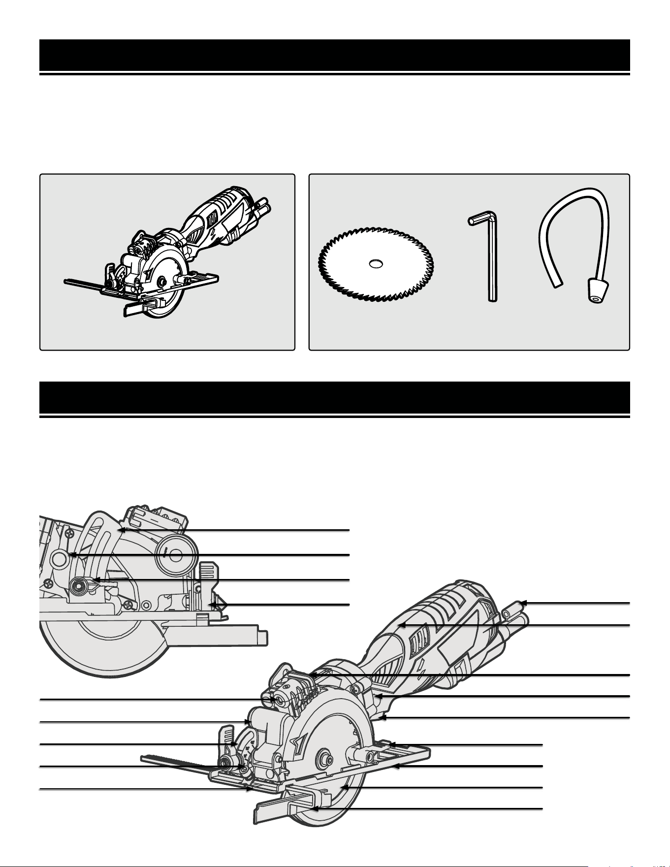
Accessories
*TCT Wood-Cutting
Blade (1)
Dust Extraction
Hose (1)
5mm Hex
Wrench (1)
Circular Saw
KNOW YOUR CIRCULAR SAW
TOOL PURPOSE
Easily make miter cuts and rough cuts on large sheets of material with your WEN Circular Saw. Refer to the follow-
ing diagrams to become familiarized with all the parts and controls of your circular saw. The components will be
referred to later in the manual for assembly and operation instructions.
Laser Power Switch
Hex Key Storage
Blade Release
Power Switch
Lower Guard Lever
Base Plate
Blade
Rip Fence
Cutting Notch
Fence Lock
Depth Scale
Laser
Handle
Dust Port
Cutting Depth Scale
Spindle Lock
Depth Locking Lever
Bevel Locking Lever
10
INSTALLING/REPLACING THE SAW BLADE
Use saw blades with 4-1/2 inch (115 mm) diameter and 3/8 inch (10 mm) arbor. Do not use a blade that does not
match the diameter or arbor size. The pre-installed blade has a body that is 1.2 mm thick and teeth that are 1.8 mm
thick . Do not use a blade that is thicker than the included blades, as this will prevent the arbor screw from properly
securing the blade. Replacement saw blades (model BL11510W) can be purchased from wenproducts.com.
Blade
Model
Blade Type Suitable Materials
Body
Thickness
Teeth
Thickness
Max Speed
BL11510W
TCT Wood-Cutting Blade
(24 Teeth)
Softwood, hardwood
and plastics
1.2 mm 1.8 mm 7,000 RPM
ASSEMBLY & ADJUSTMENTS
WARNING! To avoid injury from accidental startups, be sure that the tool is switched off and disconnected
from the power supply before inspecting the unit, making adjustments, or changing accessories.
NOTE: The quality of the cut depends on the condition of the saw
blade. Never use a dull, rusty, or damaged blade. Before opera-
tion, check the condition of the blade and replace if the blade is
worn-out or damaged.
WARNING! Wear gloves when handling saw blades to prevent injuries in case the blade teeth are acciden-
tally contacted.
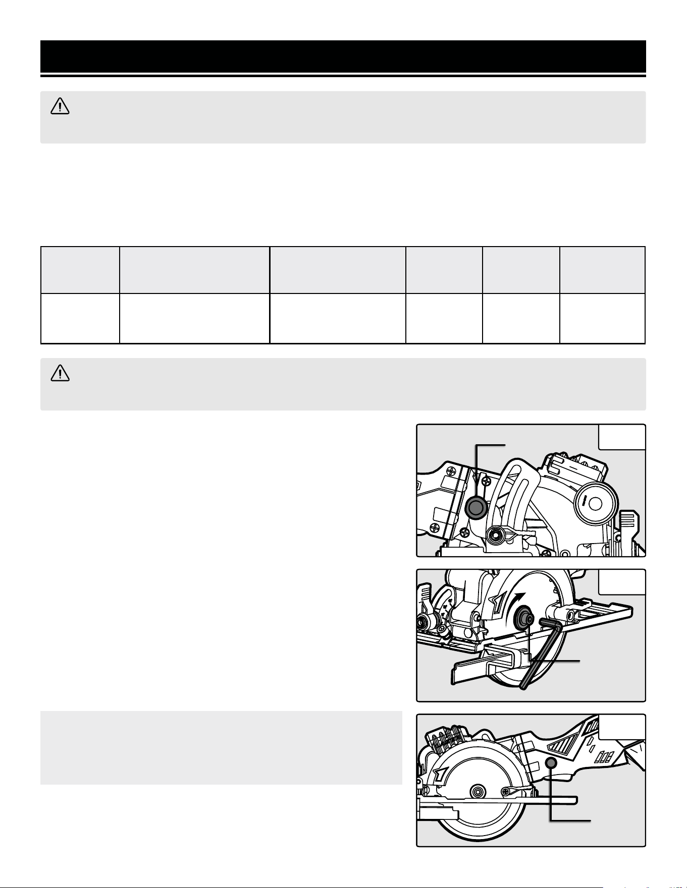
1. Unplug your mini circular saw from the power source.
2. Press down the spindle lock (Fig. 1 - 1) to prevent the blade from
spinning. With the spindle lock pressed down, use the included M5
hex wrench to loosen the arbor screw (Fig. 2 - 1) by turning it clock-
wise.
3. Remove the arbor screw, washer and outer flange.
4. Push the blade release button (Fig. 3 - 1) and swing the base plate
upwards. Carefully remove the existing blade.
5. With the base plate in the upward position, slide the new saw blade
onto the spindle. Make sure the blade teeth beneath the base plate
are pointing forward and the arrows printed on the blade point in the
clockwise direction.
6. Replace the outer flange. Press the spindle lock and replace the
arbor screw and washer. Fully tighten the arbor screw by turning it
counterclockwise with the hex wrench.
Fig. 1
Fig. 2
Fig. 3
1
1
1
11
Using the Depth Scale:
1. Unplug your mini circular saw from the power source.
2. Flip up the depth lock lever to loosen it .
3. Slide the depth lock lever so that the arrow points to your desired cutting depth indicated on the depth scale.
4. Press down on the depth lock lever to securely lock the depth setting.
Using the Edge of the Workpiece:
1. Unplug your mini circular saw from the power source.
2. Flip up the depth lock lever to loosen it and slide the lever to all the way to the top of the slot.
3. Place the base plate onto the workpiece with the saw blade positioned against the left edge of the workpiece.
4. Grip the tool and press the blade release button. Lower the blade to your desired cutting depth by observing how
deep the blade will cut relative to the top face of the workpiece.
5. Holding the saw in position at a constant depth, slide the depth lock lever to the left until it is flush against the
edge of the inner blade guard.
6. Press down on the depth lock lever to securely lock the depth setting.
Using the Depth Scale:
1. Unplug your mini circular saw from the power source.
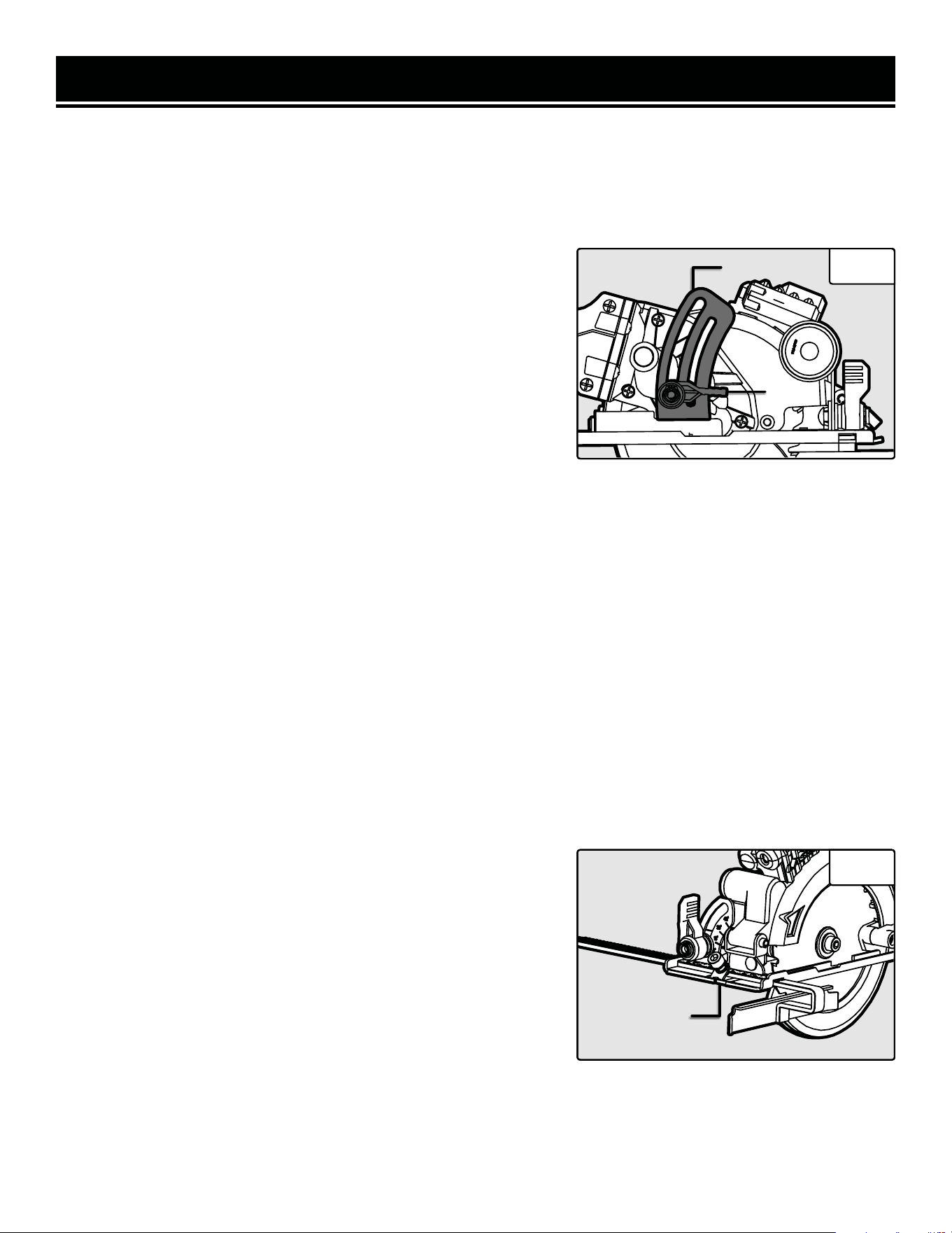
2. Flip up the depth lock lever (Fig. 4 - 1) to loosen it .
3. Slide the depth lock lever so that the arrow points to your desired
cutting depth indicated on the depth scale (Fig. 4 - 2).
4. Press down on the depth lock lever to securely lock the depth set-
ting.
Cutting
Guide
Indicator
ASSEMBLY & ADJUSTMENTS
SETTING THE DEPTH OF CUT
Before making a cut, it is important to set the correct cutting depth. The saw’s maximum cutting depth at 90° is
1-11/16 inch (43 mm) and at 45° it is 1-1/8" (28 mm). We recommend adjusting the cutting depth about 1/16 inch
(2 mm) deeper than the thickness of the material. To adjust the cutting depth, you can either refer to the depth scale,
or the edge of the workpiece.
CUTTING GUIDE INDICATOR
The cutting guide indicator (Fig. 5 - 1) can be found at the front of the
saw base. This guide helps to indicate where the cut will be occur-
ring. Before cutting, draw a guideline on the workpiece and follow the
guideline with the cutting guide to create more accurate cuts.
Fig. 5
Fig. 42
1
12
ASSEMBLY & ADJUSTMENTS
USING THE LASER
The laser (Fig. 6 - 1) located on the top of your saw can also be used
to indicate the line of cut. Unscrew the laser cover and install the two
AG13 batteries. Securely replace the laser cover. Switch the laser ON
(Fig. 6 - 2) and align the laser line with your cutting guideline.
WARNING! Do not look directly into the laser beam with un-
protected eyes. See page 8 for important rules regarding laser
safety.
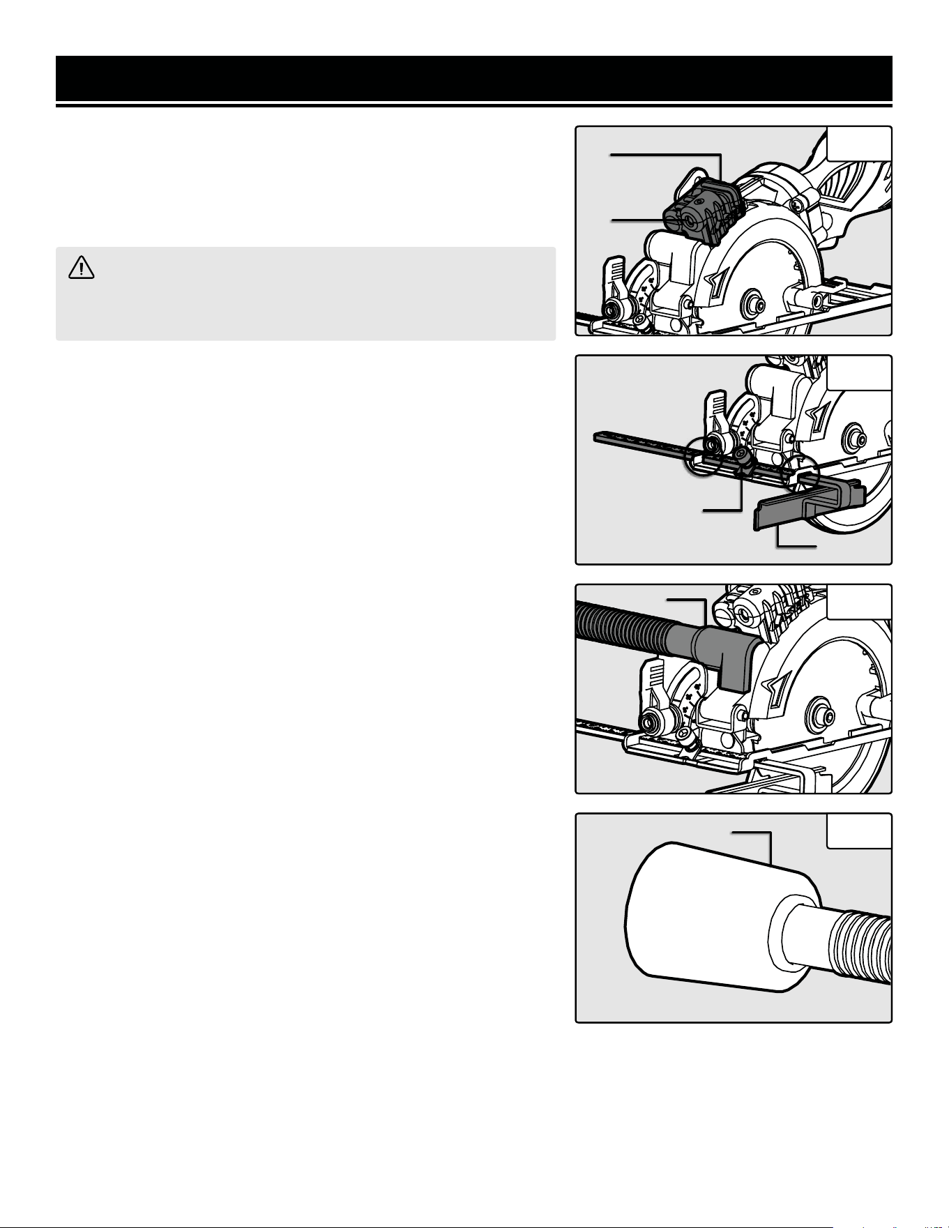
INSTALLING THE RIP FENCE
When making a rip cut along a straight edge, it is recommended to
clamp a straight edge to the workpiece or use the included rip fence.
To install the rip fence onto your saw:
1. Loosen the fence lock knob (Fig. 7 - 1) on the front of the base
plate.
2. Insert the rip fence (Fig. 7 - 2) from the left side of the tool through
the slots (Fig. 7 - Circles) on the base plate.
3. Adjust the rip fence to the desired width of cut indicated by the cut-
ting guide indicator and the markings on the rip fence.
4. Tighten the fence lock knob to secure the rip fence in place.
CONNECTING THE DUST EXTRACTION HOSE
Dust and chips will be produced during operation that can harm your
health and create a mess in your work area. It is recommended to ex-
tract the sawdust by connecting your tool to a dust extraction system
(not included) using the included dust extraction hose.
1. Unplug your mini circular saw from the power source.
2. Attach the dust extraction hose to the dust port (Fig. 8 - 1) on the
right side of your tool by pushing the hose straight onto the port.
3. Connect the rubber port end of the hose to a suitable dust extrac-
tion system. The outer diameter of the hose rubber port is a taper
from 1.35 to 1.5 inches (Fig. 9).
4. Turn on the dust collector before cutting to keep saw dust away
from your lungs and the work area.
Fig. 6
Fig. 7
Fig. 8
Fig. 9
2
1
2
1
1
1
13
ASSEMBLY & ADJUSTMENTS
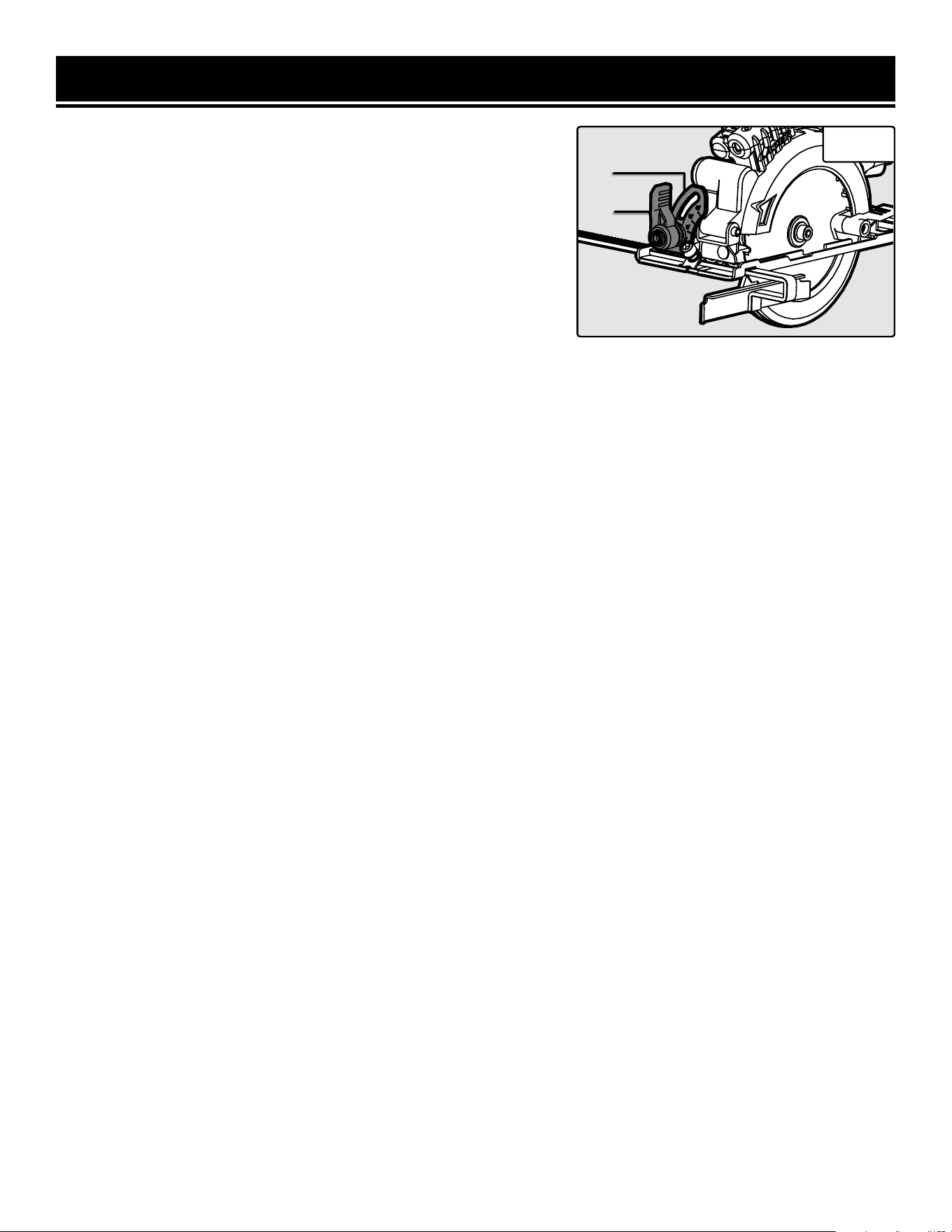
ADJUSTING THE BLADE BEVEL
Bevel your mini circular saw blade from 45° to 90° to cut your work-
piece on an angle. The saw’s maximum cutting depth at 90° is 1-11/16
inch (43 mm) and at 45° it is 1-1/8" (28 mm). Be sure to set your saw
to the proper depth for the angle you are using (see Page. 12).
1. Unplug your mini circular saw from the power source.
2. Flip up the bevel locking knob (Fig. 10 - 1) to loosen it.
3. Adjust the bevel scale (Fig. 10 - 2) to your desired angle between
45° to 90°. Your mini circular saw is pre-set to 90°, which is a per-
pendicular, straight cut through your workpiece.
4. Press down on the bevel locking knob to securely tighten the bevel
setting.
Fig. 10
2
1
14

OPERATION
PREPARING FOR OPERATION
1. Prepare the work space and position power cords away from the cutting area. Connect your saw to a dust extrac-
tion system (see page 13).
2. Ensure that the saw blade is sharp. Set the correct depth of cut for your workpiece (see page 12).
3. Draw a guideline along the desired path of the cut on the workpiece surface.
4. Place the workpiece with the “good” side down (the saw blade cuts upward through the material, and may “blow
out” the top side) on a flat supporting surface. Secure the workpiece in place with clamps or vises (not included).
To prevent cutting into the support surface, place sufficient scrap material under the workpiece.
5. Wear safety glasses, a dust mask and hearing protection. Do not wear loose clothing or jewelry, and tie back long
hair to avoid getting anything caught in the tool.
WARNING! To prevent serious injury, make sure all the instructions have been read and understood before
operating this tool. Check that the power switch mechanism works properly before plugging the tool into the
power supply.
OPERATING THE SAW
1. Hold the tool firmly in your right hand with your thumb on the blade release button and your fingers on the power
switch. Stand to the left side of the saw. (Do opposite if left-handed).
2. Set the front portion of the base plate onto the workpiece. Position the base plate with its right side resting on the
larger section of board that DOES NOT fall off when being cut. Align the cutting guide indicator (see page 12) with
the cutting guideline marked on the workpiece. Ensure that the blade is NOT in contact with the workpiece.
3. Pull the power switch back with your fingers to turn on the saw. Wait until the blade has reached full speed (ap-
proximately 3 seconds).
4. Make sure that the base plate is stable on the workpiece; this is very important especially during the start or fin-
ish of a cut. Push the blade release button with your thumb to lower the saw blade. Slowly push the blade into the
workpiece.
5. Gently push the saw forward along the cutting guideline while keeping the base plate flat against the workpiece
surface. Do not force the saw forward too quickly in order to try and hurry up the process. Let the tool work at its
own pace. Never pull the saw backwards while cutting.
WARNING! DO NOT start the saw while the blade is in contact with the workpiece, this may lead to kickback.
6. Let the saw blade run through the entire cut. Release the power switch and blade release button and allow the
blade to come to a full stop before lifting the saw off the work surface. Disconnect the saw from the power source.
WARNING! DO NOT raise the saw while it is running, this can expose you to the blade and lead to an injury.
Allow the blade to completely stop before lifting it from the work surface.
15

CAUTION! Most plastics are susceptible to damage from various types of commercial solvents. Do not use any
solvents or cleaning products that could damage the plastic parts. Some of these include but are not limited to:
gasoline, carbon tetrachloride, chlorinated cleaning solvents, and household detergents that contain ammonia.
MAINTENANCE
PREPARING FOR OPERATION
Routine inspection
Before each use, inspect the general condition of the tool. If any of these following conditions exist, do not use until
parts are replaced or the sharpener is properly repaired.
Check for:
• Loose hardware or improper mounting,
• Misalignment or binding of moving parts,
• Damaged cord/electrical wiring,
• Cracked or broken parts, and
• Any other condition that may affect its safe operation
CLEANING & STORAGE
1. After every operation, use a vacuum to remove dust and chips from the tool surfaces, motor housing and work
area. Keep the ventilation openings free from dust and debris to prevent the motor from overheating.
2. Wipe the tool surfaces clean with a soft cloth or brush. Make sure water does not get into the tool.
3. Periodically, remove the saw blade and vacuum out any dust that has accumulated in the blade housing.
WARNING! To avoid accidents, turn OFF and unplug the tool from the electrical outlet before cleaning, ad-
justing, or performing any maintenance or lubrication work.
WARNING! Any attempt to repair or replace electrical parts on this tool may be hazardous. Servicing of the
tool must be performed by a qualified technician. When servicing, use only identical WEN replacement parts.
Use of other parts may be hazardous or induce product failure.
4. Store the tool in a clean and dry place away from the reach of children.
LUBRICATION
All ball bearings are sealed and permanently lubricated. No further lubrication is required.
PRODUCT DISPOSAL
Used power tools should not be disposed of together with household waste. This product contains electronic com-
ponents that should be recycled. Please take this product to your local recycling facility for responsible disposal and
to minimize its environmental impact.
16

PROBLEM CAUSE SOLUTION
Motor does not
start.
1. Power cord damaged or not
properly plugged in.
1. Check the power cord, extension cord, power plug
and the power outlet. Make sure the outlet is func-
tional. Do not use the tool if any cord is damaged.
2. Defective power switch.
2. Stop using the tool and contact customer service at
1-847-429-9263, M-F 8-5 CST for assistance.
3. Motor carbon brushes (Part No.
36703-011) are worn.
3. Stop using the tool and contact customer service at
1-847-429-9263, M-F 8-5 CST for assistance.
4. Defective Motor.
4. Stop using the tool and contact customer service at
1-847-429-9263, M-F 8-5 CST for assistance.
Ineffective
cutting.
1. Cutting blade edges are dull /
worn.
1. Replace the cutting blade (see page 12).
2. Blade not suitable for the mate-
rial being cut.
2. Select the correct cutting blade (see page 11) for
your material.
3. The blade is not installed prop-
erly.
3. See instructions for properly installing the blade on
page 11.
WARNING! Stop using the tool immediately if any of the following problems occur. Repairs and replace-
ments should only be performed by an authorized technician. For any questions, please contact our customer
service at 1-847-429-9263, M-F 8-5 CST or email us at [email protected]
TROUBLESHOOTING GUIDE
17
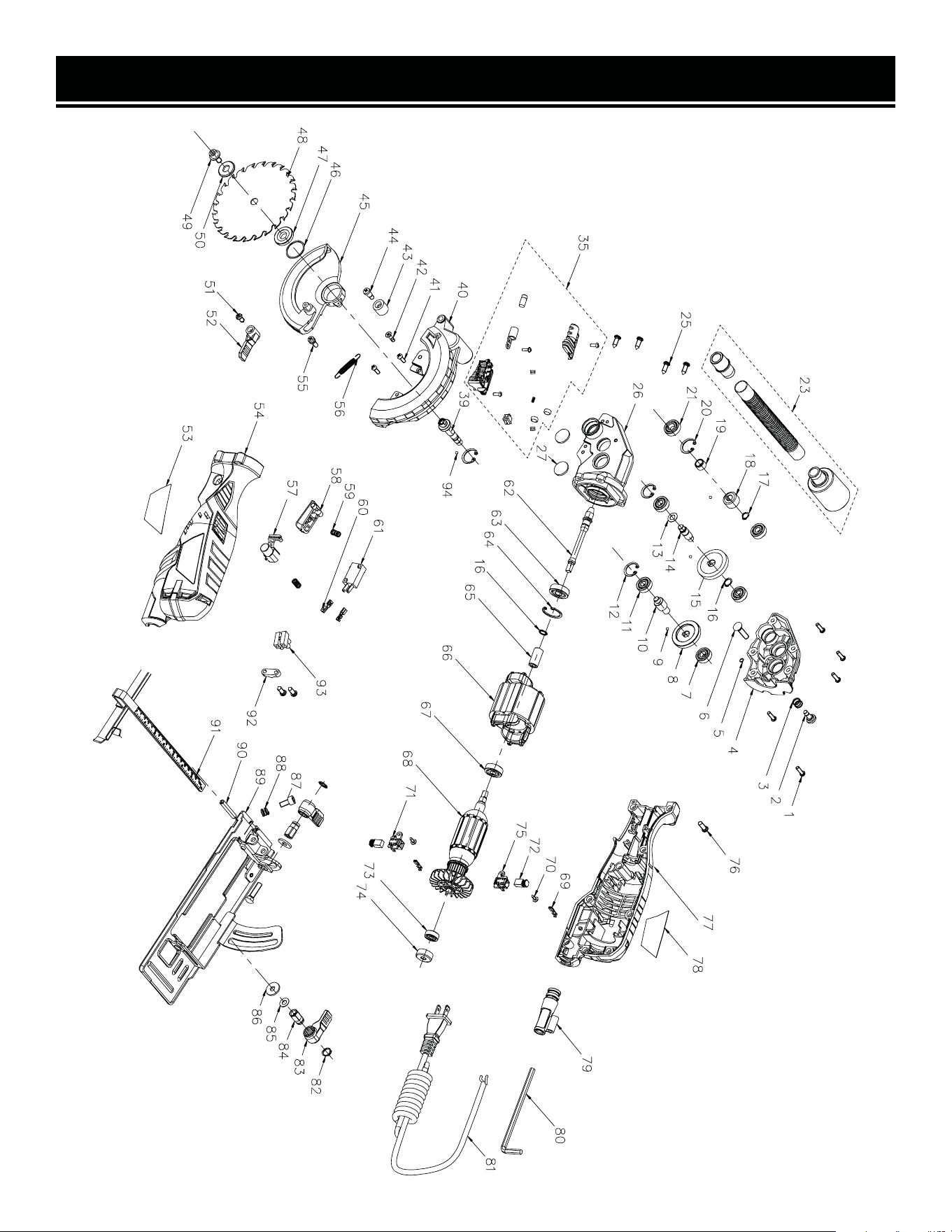
EXPLODED VIEW & PARTS LIST
18

No. Part No. Description Qty.
1 3625-001
Screw With Washer
M4x14
5
2 3625-002 Spindle Lock Button 1
3 3625-003 Spindle Lock Spring 1
4 3625-004 Gear Housing 1
5 3625-005 Baffle D4 1
6 3625-006
Square Neck Bolt
M6×26
2
7 3625-007 Bearing 698 1
8 3625-008 Spiral Bevel Gear 1
9 3625-009 Ball Bearing 3
10 3625-010 Gear Shaft 1
11 3625-011 Bearing 607-2z 4
12 3625-012 C-Clip 2
13 3625-013 Spacer 1
14 3625-014 Intermediate Shaft 1
15 3625-015 Large Gear 1
16 3625-016 O-Ring 2
17 3625-017 C-Clip 1
18 3625-018 Pinion 1
19 3625-019 Spacer Sleeve 1
20 3625-020 C-Clip 2
21 3625-021 Bearing 699 1
23 3625-023 Dust Hose Assembly 1
25 3625-025
Self-Tapping Screw
ST4.2×14
6
26 3625-026 Gear Housing, Left 1
27 3625-027 Cover 2
35 3625-035 Laser Assembly 1
No. Part No. Description Qty.
39 3625-039 Blade Arbor 1
40 3625-040 Fixed Blade Guard 1
41 3625-041
Screw With Washer
M4x12
2
42 3625-042
Cross-Shaped Screw
M4x12
1
43 3625-043
Rubber Block For Lower
Guard
1
44 3625-044 Screw For Rubber Block 1
33 3625-033 Blade Arbor Screw 1
34 3625-034 Left Label 1
35 3625-035 Left Housing 1
36 3625-036 Screw St4.2x12 1
37 3625-037 Lever For Blade Cover 1
38 3625-038 Reset Spring 1
39 3625-039 Screw For Reset Spring 1
40 3625-040
Screw With Washer
M4x12
2
41 3625-041 Power Switch Button 1
42 3625-042 Spindle Lock Cap 1
43 3625-043 Spindle Lock Spring 2
44 3625-044 Screw For Rubber Block 1
45 3625-045 Blade Cover 1
46 3625-046 Baffle 1
47 3625-047 Inner Flange 1
48 BL11510W Blade, TCT, 115 mm 1
EXPLODED VIEW & PARTS LIST
NOTE: Not all parts may be available for purchase. Parts and accessories that wear down over the course of
normal use are not covered under the warranty.
19

No. Part No. Description Qty.
49 3625-049 Blade Arbor Screw 1
50 3625-050 Outer Flange 1
51 3625-051 Screw St4.2x12 1
52 3625-052 Lever For Blade Cover 1
53 3625-053 Left Label 1
54 3620-057 Left Housing 1
55 3625-055 Screw For Reset Spring 1
56 3625-056 Reset Spring 1
57 3620-067 Switch Locking Button 1
58 3620-076 Switch Trigger 1
59 3625-059 Spindle Lock Spring 2
60 3625-060
Switch Terminal Insert,
4.8x0.8
2
61 3620-075 Power Switch 1
62 3620-037 Connecting Rod 1
63 3620-038 Bearing 609-2z 1
64 3620-039 C-Clip 1
65 3620-041 Connecting Sleeve 1
66 3620-042 Stator Assembly 1
67 3620-038 Bearing 608-2z 1
68 3620-043 Rotor Assembly 1
69 3620-044
Brush Terminal Insert,
2.8x0.8
2
70 3625-070
Self-Tapping Screw
With Washer ST2.9×10
2
No. Part No. Description Qty.
71 3620-046 Lower Brush Holder 1
72 3620-045 Carbon Brush 2
73 3620-048 Bearing 606-2z 1
74 3620-049 Bearing Sleeve 1
75 3620-050 Upper Brush Holder 1
76 3625-076
Self-Tapping Screw
With Washer ST4.2×16
9
77 3620-092 Right Housing 1
78 3625-078 Right Label 1
79 3625-079 Power Cord Sheath 1
80 3625-080 Hex Wrench 1
81 3625-081 Power Cord 1
82 3625-082 C-Clip for Shaft D10 2
83 3625-083 Depth Locking Lever 2
84 3625-084 M6 Locking Pin 2
86 3625-086 Flat Washer M6 2
87 3625-087 Screw M6x12 1
88 3625-088
Rip Fence Locking
Spring
1
89 3625-089 Base Plate 1
90 3625-090
Cylindrical Spring Pin
D6x35
1
91 3625-091 Rip Fence 1
92 3625-092 Cord Clamp 1
93 3625-093 Relay 1
94 3625-094 Ball Bearing 1
EXPLODED VIEW & PARTS LIST
NOTE: Not all parts may be available for purchase. Parts and accessories that wear down over the course of
normal use are not covered under the warranty.
20

WARRANTY STATEMENT
WEN Products is committed to building tools that are dependable for years. Our warranties are consistent with this
commitment and our dedication to qualit
y.
LIMITED WARRANTY OF WEN PRODUCTS FOR HOME USE
GRE
AT LAKES TECHNOLOGIES, LLC (“Seller”) warrants to the original purchaser only, that all WEN
consumer
power tools will be free from defects in material or workmanship during personal use for a period of two (2) years
used
for professional or commercial use. Purchaser has 30 days from the date of purchase to report missing or
damaged parts.
SELLER’S
SOLE OBLIGATION AND YOUR EXCLUSIVE REMEDY under this Limited Warranty and, to the extent per-
mitted
by law, any warranty or condition implied by law, shall be the replacement of parts, without charge, which a
re
defective
in material or workmanship and which have not been subjected to misuse, alteration, careless handling,
misrepair
, abuse, neglect, normal wear and tear,
improper maintenance, or other conditions adversely affecting the
Product
or the component of the Product, whether by accident or intentionally, by persons other than Seller. To
make
a claim under this Limited Warranty, you must make sure to keep a copy of your proof of purchase that
clearly
-
dor
of Great Lakes Technologies, LLC. Purchasing through third party vendors, including but not limited to garage
sales,
pawn shops, resale shops, or any other secondhand merchant, voids the warranty included with this
product.
Contact [email protected] or 1-847-429-9263 with the following information to make arrangements:
your
shipping address, phone number, serial number, required part numbers, and proof of purchase. Damaged
or
defective parts and products may need to be sent to WEN before the replacements can be shipped out.
-
turning
a product for warranty service, the shipping charges must be prepaid by the purchaser. The product
must
be
shipped in its original container (or an equivalent), properly packed to withstand the hazards of shipment. The
product
must be fully insured with a copy of the proof of purchase enclosed. There must also be a description of
the
will be returned and shipped back to the pur
chaser at no charge for addresses within the contiguous United States.
THIS
LIMITED WARRANTY DOES NOT APPLY TO ITEMS THAT WEAR OUT FROM REGULAR USAGE OVER TIME,
INCLUDING
BELTS, BRUSHES, BLADES, BATTERIES, ETC. ANY IMPLIED WARRANTIES SHALL BE LIMITED IN
DUR
ATION TO TWO (2) YEARS FROM DATE OF PURCHASE. SOME STATES IN THE U.S. AND SOME CANADIAN
PROVINCES
DO NOT ALLOW LIMITATIONS ON HOW LONG AN IMPLIED WARRANTY LASTS, SO THE ABOVE LIMI-
TAT
ION MAY NOT APPLY TO YOU.
IN
NO EVENT SHALL SELLER BE LIABLE FOR ANY INCIDENTAL OR CONSEQUENTIAL DAMAGES (INCLUDING
BUT
NOT LIMITED TO LIABILITY FOR LOSS OF PROFITS) ARISING FROM THE SALE OR USE OF THIS PRODUCT.
SOME ST
ATES IN THE U.S. AND SOME CANADIAN PROVINCES DO NOT ALLOW THE EXCLUSION OR LIMITAT
ION
OF
INCIDENTAL OR CONSEQUENTIAL DAMAGES, SO THE ABOVE LIMITATION OR EXCLUSION MAY NOT APPLY
TO YOU
.
THIS
LIMITED WARRANTY GIVES YOU SPECIFIC LEGAL RIGHTS, AND YOU MAY ALSO HAVE OTHER RIGHTS
WHICH
VARY FROM STATE TO STATE IN THE U.S., PROVINCE TO PROVINCE IN CANADA AND FROM COUNTRY
TO COUNT
RY.
THIS
LIMITED WARRANTY APPLIES ONLY TO ITEMS SOLD WITHIN THE UNITED STATES OF AMERICA, CANA-
DA
AND THE COMMONWEALTH OF PUERTO RICO. FOR WARRANTY COVERAGE WITHIN OTHER C
OUNTRIES,
CONT
ACT THE WEN CUSTOMER SUPPORT LINE. FOR WARRANTY PARTS OR PRODUCTS REPAIRED UNDER
W
ARRANTY SHIPPING TO ADDRESSES OUTSIDE OF THE CONTIGUOUS UNITED STATES, ADDITIONAL
SHIPPING
CHARGES MAY APPLY.
21

NOTES
22

NOTES
23

THANKS FOR
REMEMBERING
V. 2023.03.14