
© 2024 GeoVision, Inc. All rights reserved.
Under the copyright laws, this manual may not be copied, in whole or in part,
without the written consent of GeoVision.
Every effort has been made to ensure that the information in this manual is
accurate. GeoVision, Inc. makes no expressed or implied warranty of any kind
and assumes no responsibility for errors or omissions. No liability is assumed
for incidental or consequential damages arising from the use of the information
or products contained herein. Features and s
pecifications are subject to
change without notice.
GeoVision, Inc.
9F, No. 246, Sec. 1, Neihu Rd.,
Neihu District, Taipei, Taiwan
Tel: +886-2-8797-8377
Fax: +886-2-8797-8335
http://www.geovision.com.tw
Trademarks used in this manual: GeoVision, the GeoVision logo and GV
series products are trademarks of GeoVision, Inc. Windows is the registered
trademark of Microsoft Corporation.
November2024
Scan the following QR codes for product warranty and technical support
policy:
[Warranty] [Technical Support Policy]

Contents
1. Overview ...................................................................................................... 2
2. Configuration Guide ..................................................................................... 3
2.1. Power ................................................................................................. 3
2.2. Connecting to the Network ................................................................. 4
2.3. Starting the Web-Based Configuration Utility ...................................... 5
2.4. Logging In ........................................................................................... 6
2.5. Web-Based Switch Configuration ....................................................... 7
3. Web Smart Configuration ............................................................................. 7
3.1. Homepage .......................................................................................... 7
3.2. System Settings .................................................................................. 8
3.2.1. Device Info ................................................................................ 8
3.2.2. IP Settings ................................................................................. 8
3.2.3. WEB Settings ............................................................................ 9
3.2.4. Telnet Settings ........................................................................... 9
3.2.5. User Management ..................................................................... 9
3.2.6. Upgrade ................................................................................... 10
3.2.7. Device Management ................................................................ 10
3.3. Monitoring ......................................................................................... 11
3.3.1. Port Statistics .......................................................................... 11
3.3.2. Cable Diagnostics.................................................................... 12
3.3.3. Loop Guard ............................................................................. 13
3.3.4. IGMP Snooping ....................................................................... 13
3.4. Switch Settings ................................................................................. 14
3.4.1. Port Settings ............................................................................ 14
3.4.2. Port Mirroring ........................................................................... 15
3.4.3. Port Isolation ........................................................................... 15
3.4.4. Jumbo Frame .......................................................................... 15
3.4.5. Green Enable .......................................................................... 16
3.4.6. Static MAC .............................................................................. 16
3.4.7. Filter MAC ............................................................................... 17
3.4.8. Search MAC ............................................................................ 17
3.4.9. MAC List .................................................................................. 17
3.4.10. DHCP Snooping .................................................................... 18
3.5. VLAN Settings .................................................................................. 19
3.5.1. VLAN Member ......................................................................... 19
3.5.2. VLAN Settings ......................................................................... 20
3.6. QoS Settings .................................................................................... 21
3.6.1. Port Rate ................................................................................. 21
3.6.2. Storm Control .......................................................................... 22
3.6.3. QoS Property ........................................................................... 23
3.6.4. COS Priority Mapping .............................................................. 24
3.6.5. DSCP Priority Mapping ............................................................ 25

3.6.6. Inner Priority Mapping ............................................................. 26
3.6.7. Queue Scheduling ................................................................... 27
3.7. PoE Settings ..................................................................................... 28
3.7.1. PoE Global Info ....................................................................... 28
3.7.2. PoE Basic Settings .................................................................. 29
3.7.3. PD Alive ................................................................................... 30
3.8. Onvif ................................................................................................. 31
4. Frequently Asked Questions ...................................................................... 32

1
Disclaimers
Preface
Reader object
This document is suitable for the following people
⚫ Network Engineer
⚫ Technical Promotion Personnel
⚫ Network Administrator
Agreement in this book
1. Command line format Convention
The meaning of the command line format is as follows:
Bold: the command line keywords (the parts that must be input as they remain
unchanged in the command) are expressed in bold font.
Italics: command line parameters (parts of the command that must be
replaced by actual values) are expressed in italics.
[ ]: indicates the part enclosed by [ ], which is optional during command
configuration.
{ x | y | ... }: Indicates that one of two or more options is selected.
[ x | y | ... ]: Indicates to select one or none of two or more options.
//: a line starting with a double slash is represented as a comment line.
2. Description
⚫ Some port types illustrated in this manual may be inconsistent with the
actual situation. In actual operation, it is necessary to configure according
to the port types supported by each product.
⚫ The display information illustrated in this manual may contain the contents
of other product series (such as product model, description, etc.), and the
specific display information shall be subject to the actual equipment
information.

2
Web Smart Function Configuration
1. Overview
Web Smart refers to the device web management system, that is, the web
management system that manages or configures the device, and manages
the device by accessing Web Smart using a browser (such as Chrome).
Web management includes two parts: Web server and Web client. The Web
server is integrated on the device to receive and process the requests sent by
the client and return the processing results to the client. The Web client
usually refers to the browser, such as Chrome, Microsoft Edge (including IE
Mode), and Firefox.
3
2. Configuration Guide
This section provides an introduction to the web-based configuration utility, and
covers the following topics:
• Powering on the device
• Connecting to the network
• Starting the web-based configuration utility
2.1. Power
Connecting to Power
Power down and disconnect the power cord before servicing or wiring a
switch.
Do not disconnect modules or cabling unless the power is first switched
off. The device only supports the voltage outlined in the type plate. Do
not use any other power components except those specifically
designated for the switch.
Disconnect the power cord before installation or cable wiring.
Connect the AC power connector on the back panel of the switch to the external
power source with the included power cord, and check the power LED is on.

4
2.2. Connecting to the Network
To connect the switch to the network:
1. Connect an Ethernet cable to the Ethernet port of a computer
2. Connect the other end of the Ethernet cable to one of the numbered
Ethernet ports of the switch. The LED of the port lights if the device connected
is active.
3. Repeat Step 1 and Step 2 for each device to connect to the switch.
We strongly recommend using CAT-5E or better cable to connect
network devices. When connecting network devices, do not exceed
the maximum cabling distance of 100 meters (328 feet). It can take up
to one minute for attached devices or the LAN to be operational after
it is connected. This is normal behavior.
Connect the switch to end nodes using a standard Cat 5/5e Ethernet cable
(UTP/STP) to connect the switch to end nodes as shown in the illustration below.
Switch ports will automatically adjust to the characteristics (MDI/MDI-X, speed,
duplex) of the device to which the switch is connected.
5
2.3. Starting the Web-Based Configuration Utility
This section describes how to navigate the web-based switch configuration
utility. Be sure to disable any pop-up blocker.
Launching the Configuration Utility
To open the web-based configuration utility:
1. Open a Web browser.
2. Enter the IP address of the device you are configuring in the address bar
on the browser (factory default IP address is 192.168.0.250) and then press
Enter.
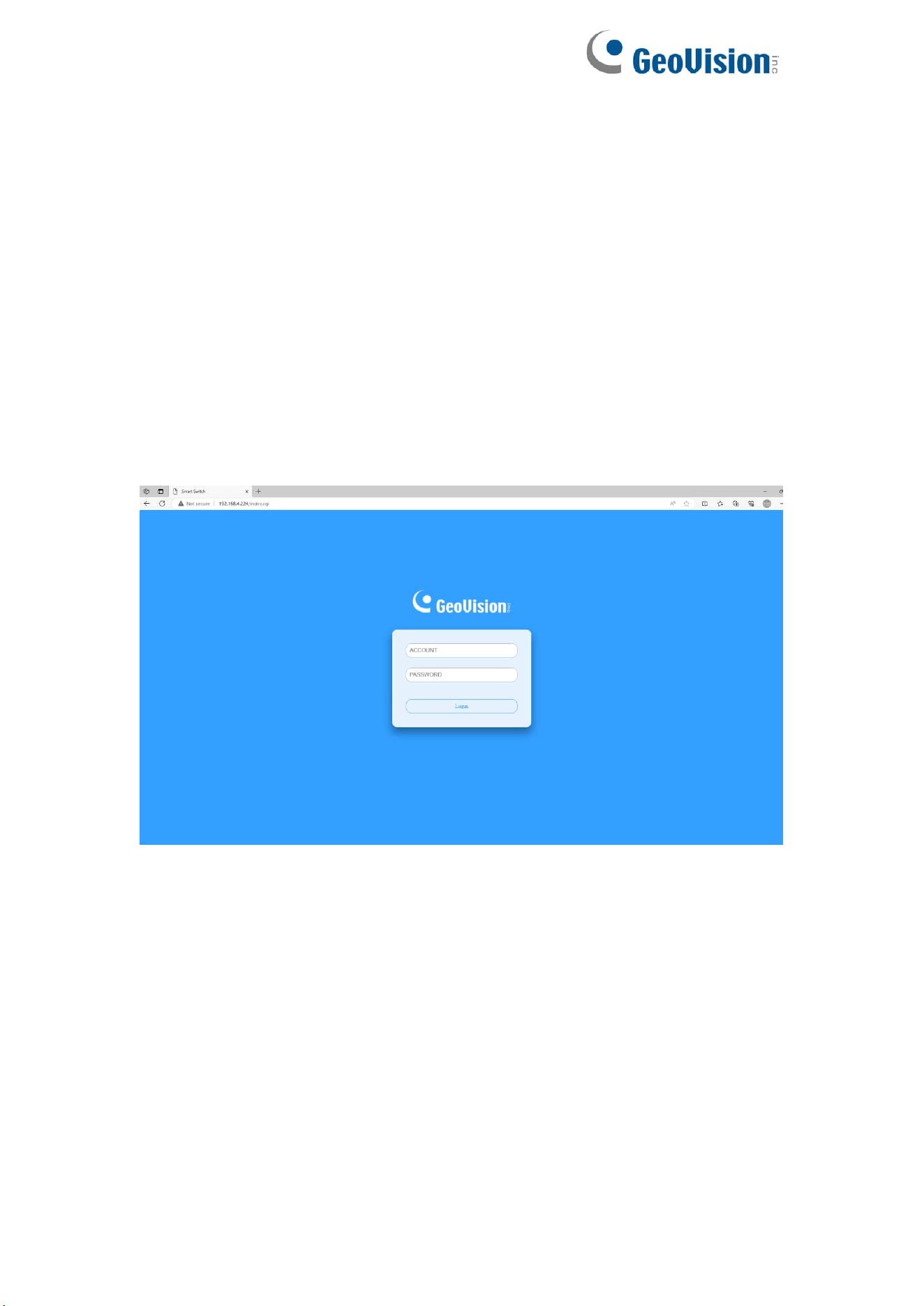
After a successful connection, the login window displays.
6
2.4. Logging In
The default username is admin and the default password is admin.
To log in to the device configuration utility:
1. Enter the default user ID (admin) and the default password (admin).
2. If this is the first time that you logged on with the default user ID (admin)
and the default password (admin), it is recommended that you change your
password immediately.
When the login attempt is successful, the System Information window displays.
If you entered an incorrect username or password, an error message appears
and the Login page remains displayed on the window.
By default, the application logs out after five minutes of inactivity.
To log out, click Logout at the top right corner of any page. The system logs
out of the device.
When a timeout occurs or you intentionally log out of the system, a message
appears and the Login page appears, with a message indicating the logged-
out state. After you log in, the application returns to the initial page.
7
2.5. Web-Based Switch Configuration
The WebSmart switch software provides Easy Web Smart functionality for
switches in your networks. This chapter describes how to use the web-based
management interface (Web UI) to configure the switch’s features.
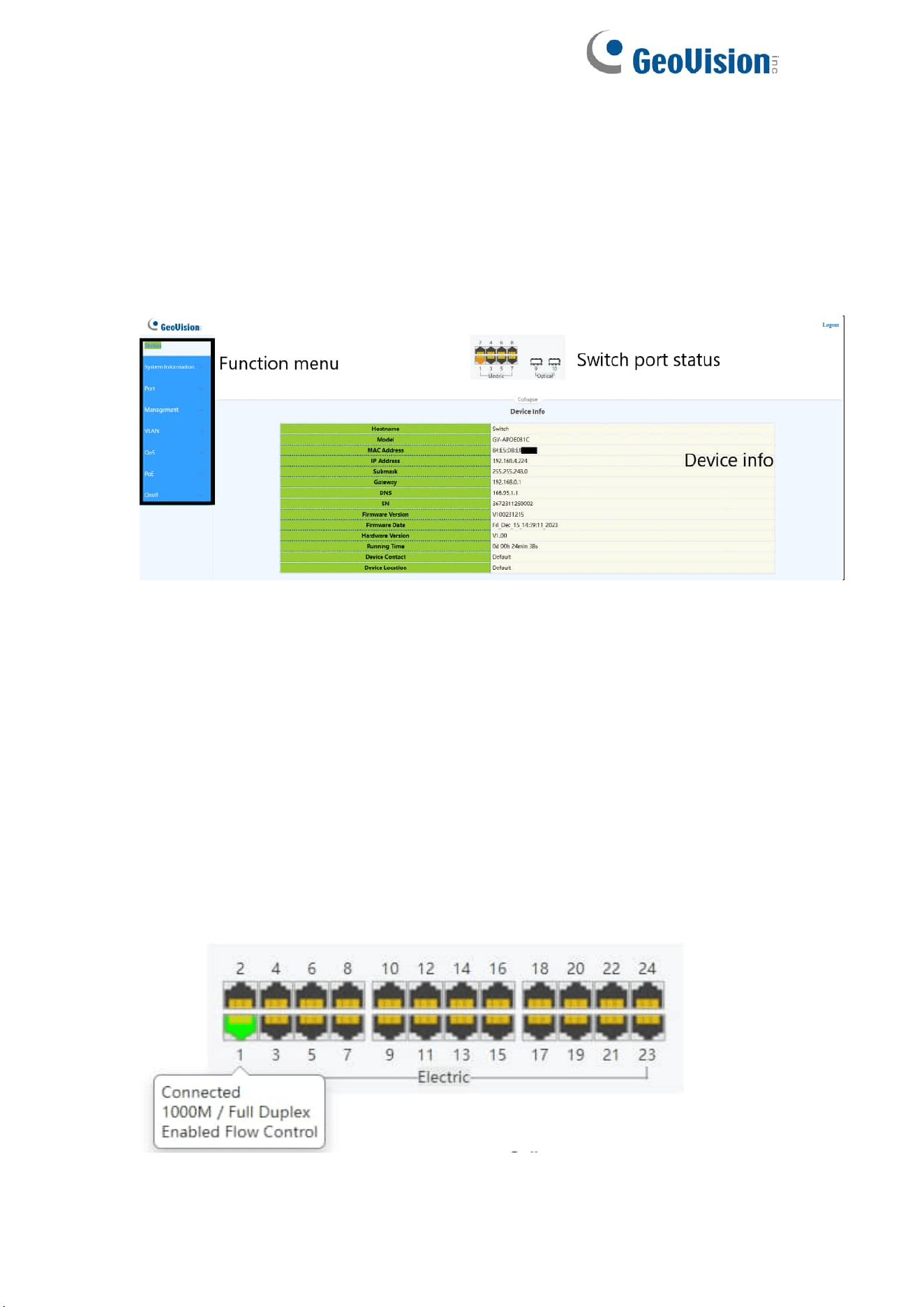
For the purposes of this manual, the user interface is separated into three
sections, as shown in the following figure:
As you can see, the page is divided into two parts:
The left part is the menu bar, which displays the links of all configuration
functions of the equipment, such as monitoring management and switch
configuration module.
The right part is the content area, which is divided into upper and lower parts.
The upper side is the port status bar and Logout button, and the lower side is
the page content presentation and configuration area.
Port Status Bar:
Move the mouse to the port to display the basic status of the port (including
port connection status, rate duplex and flow control status). Click Collapse to
hide the port status bar and display more content areas to view other
configuration information.
8
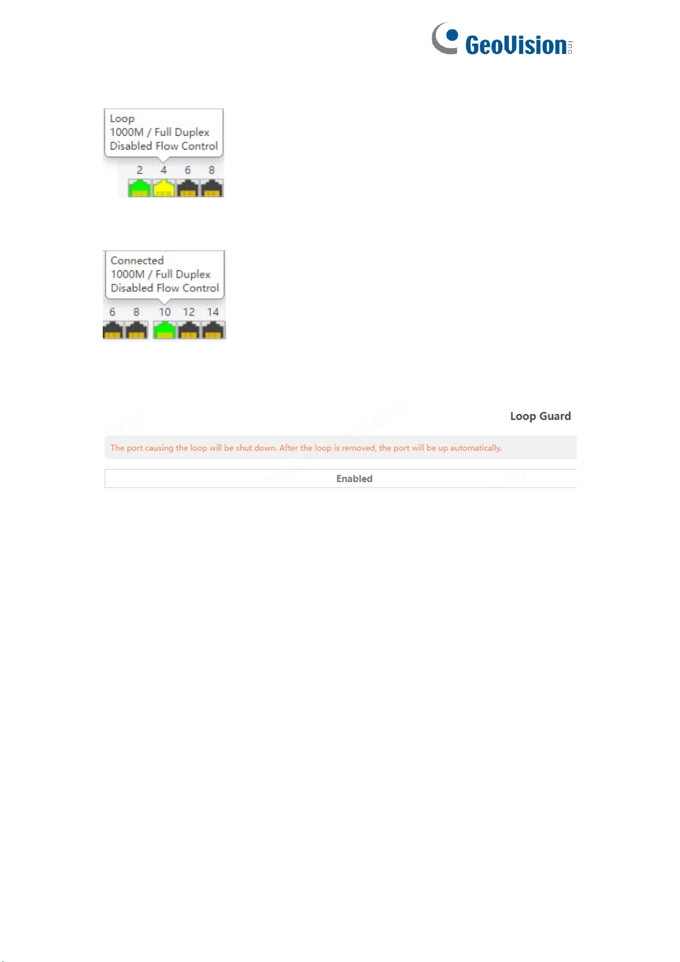
When a loop appears on the port, the port icon displays yellow
When the port works normally, the port icon displays green
The content area sometimes presents orange text (indicating the description
of the function block)

7
3. Web Smart Configuration
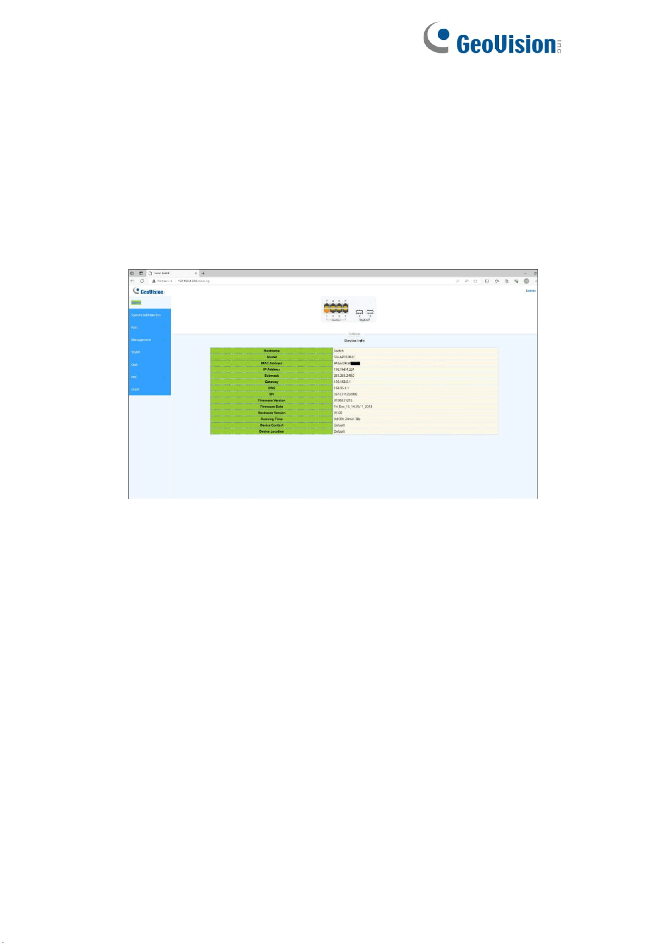
3.1. Homepage
The homepage interface displays the basic information of the device.
8
3.2. System Settings
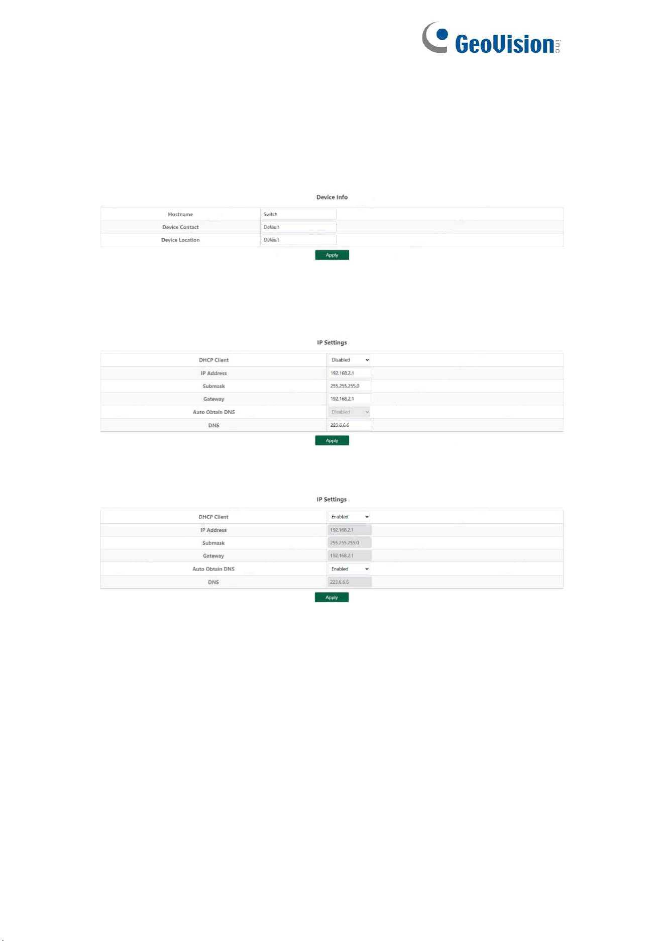
3.2.1. Device Info
Configure the information of the device, including Device Name, Device
Contact and Device Location.
3.2.2. IP Settings
Configure device management IP (default static IP: 192.168.0.250)
When "Auto Obtain IP" is displayed as follows:
Tips:
1. When configuring IP, the device will be disconnected briefly. If automatic IP
acquisition is enabled, you need to obtain the configuration IP from the uplink
device or web management through device management IP:
10.XX.XX.XX(XX.XX.XX is the last two digits of the MAC address of the
current device).
9
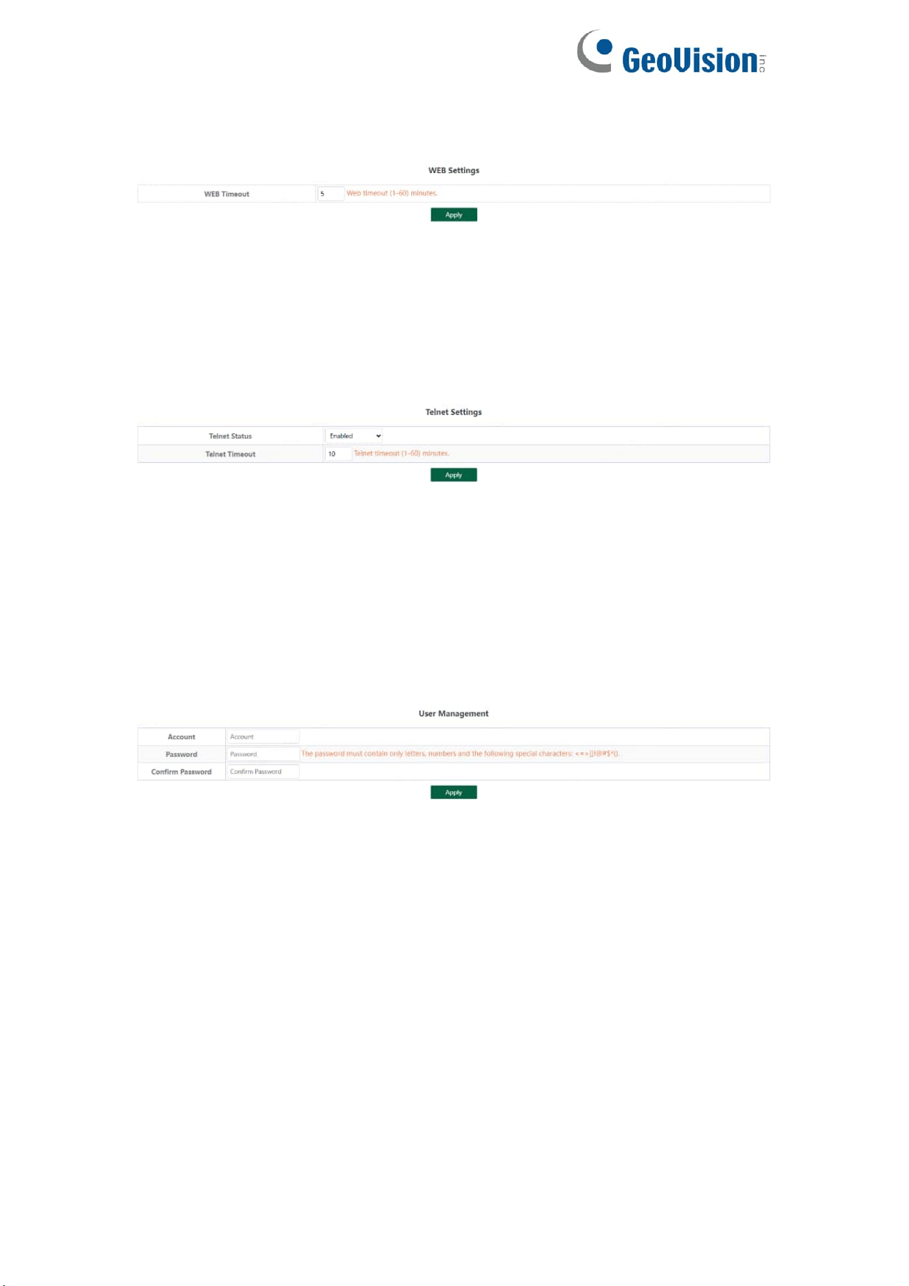
3.2.3. WEB Settings
Configure web page timeout, default is 5 minutes.
Tips:
1. The timeout can be configured for 1-60 minutes
3.2.4. Telnet Settings
Configure Telnet timeout, default is 10 minutes.
Tips:
1. The timeout can be configured for 1-60 minutes
3.2.5. User Management
Configure the account and password for web page login (The password must
contain 6-16 characters and contain only letters, numbers and the following
special characters: <=>[]!@#$*().)
10
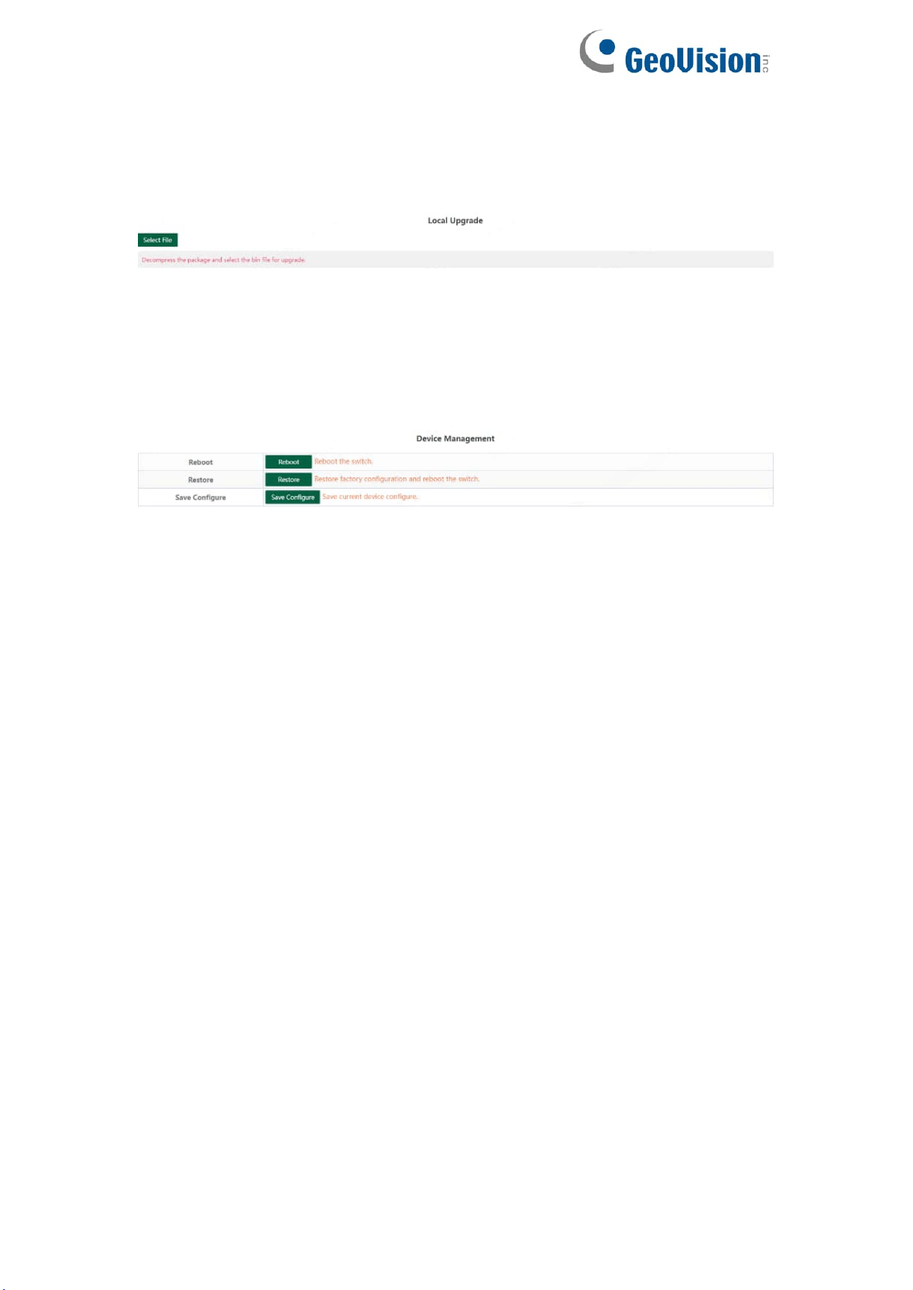
3.2.6. Upgrade
Click Select File and select the software package you want to upgrade in the
pop-up file selection box (the software upgrade package is a file in xxx.bin
format).
3.2.7. Device Management
Click Reboot to restart the equipment.
Click Restore to restore the factory configuration and restart the equipment.
Click Save Configure to save current device configure.
11
3.3. Monitoring
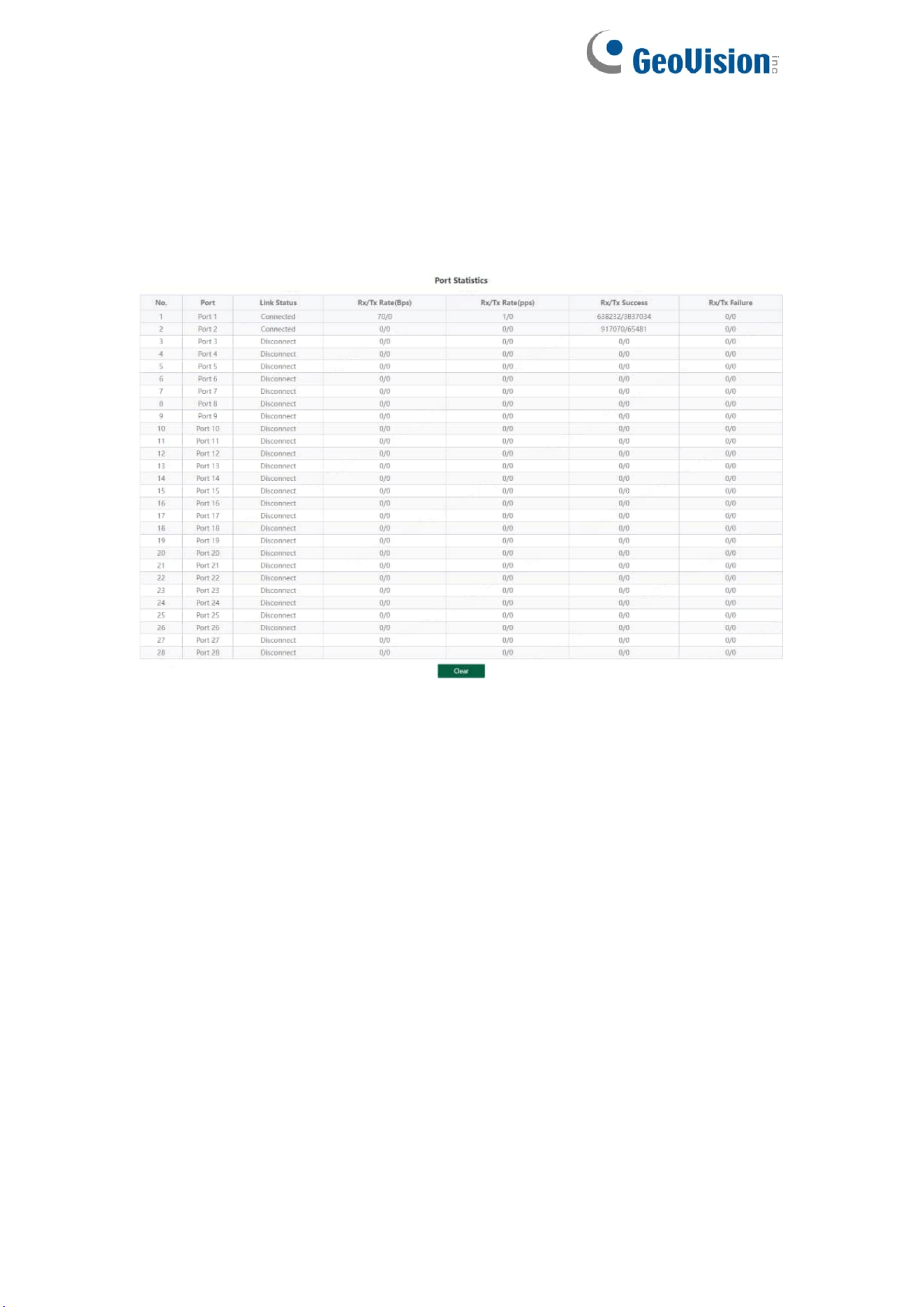
3.3.1. Port Statistics
The Port Statistics page displays the data statistics and status of the device
port, such as the port sending and receiving rate, sending and receiving
packets, etc.
12
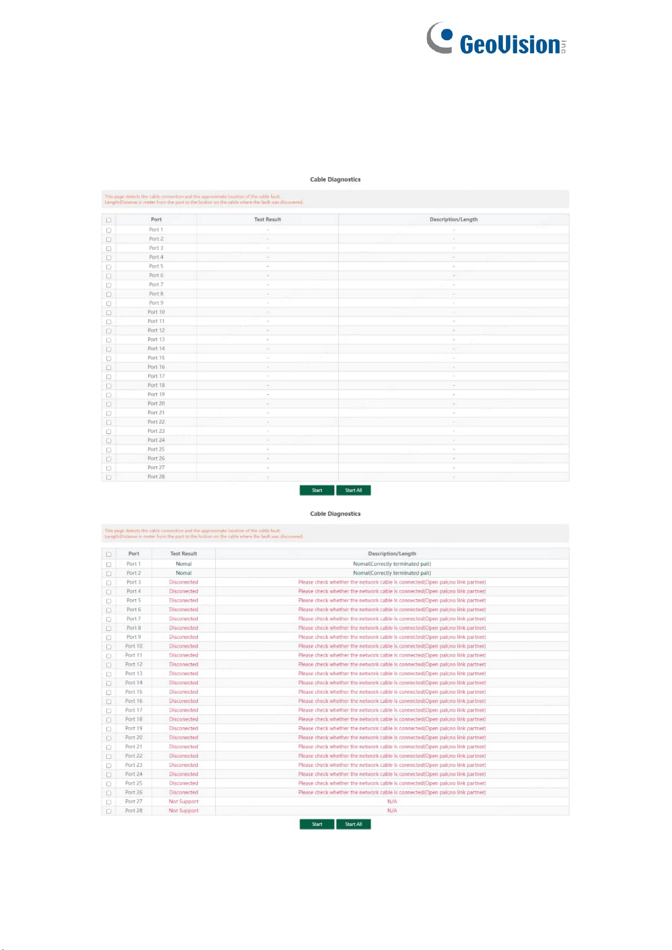
3.3.2. Cable Diagnostics
You can roughly understand the cable condition of the corresponding port
through cable detection (such as whether the cable is short circuited,
disconnected, etc.).
Click Start All and wait for the test results to return.
13
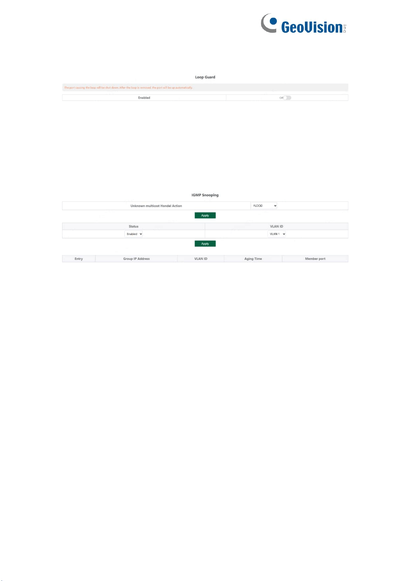
3.3.3. Loop Guard
Configure enable loop guard
Tips:
The port causing the loop will be shut down. After the loop is removed, the
port will be up automatically. (Default is disable).
3.3.4. IGMP Snooping
Configure IGMP Snooping
Unknown multicast Handel Action can configure FLOOD or DROP, Select the
VLAN you want to enable and click Apply to save.
Tips:
IGMP Snooping only supports DIP mode, the maximum multicast entry is 10,
Unknown multicast Handel Action default is flood.
14
3.4. Switch Settings
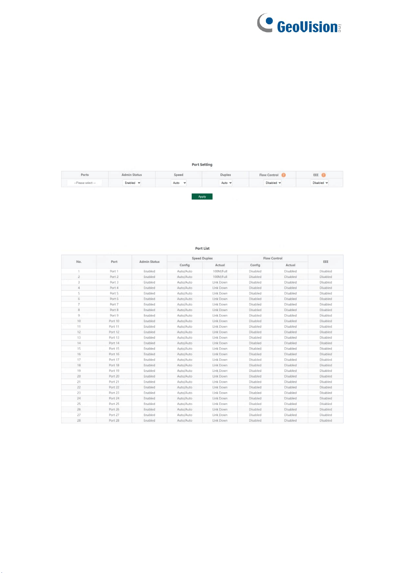
3.4.1. Port Settings
Port configuration can batch configure the status, speed, duplex, flow control
and EEE properties of ports. The page is divided into two parts:
Configuration part:
Select the port to be configured, then select each attribute to be configured,
and click Apply to distribute the configuration.
Display part:
Displays the configuration attributes and actual effective attributes of each
port of the device.
15
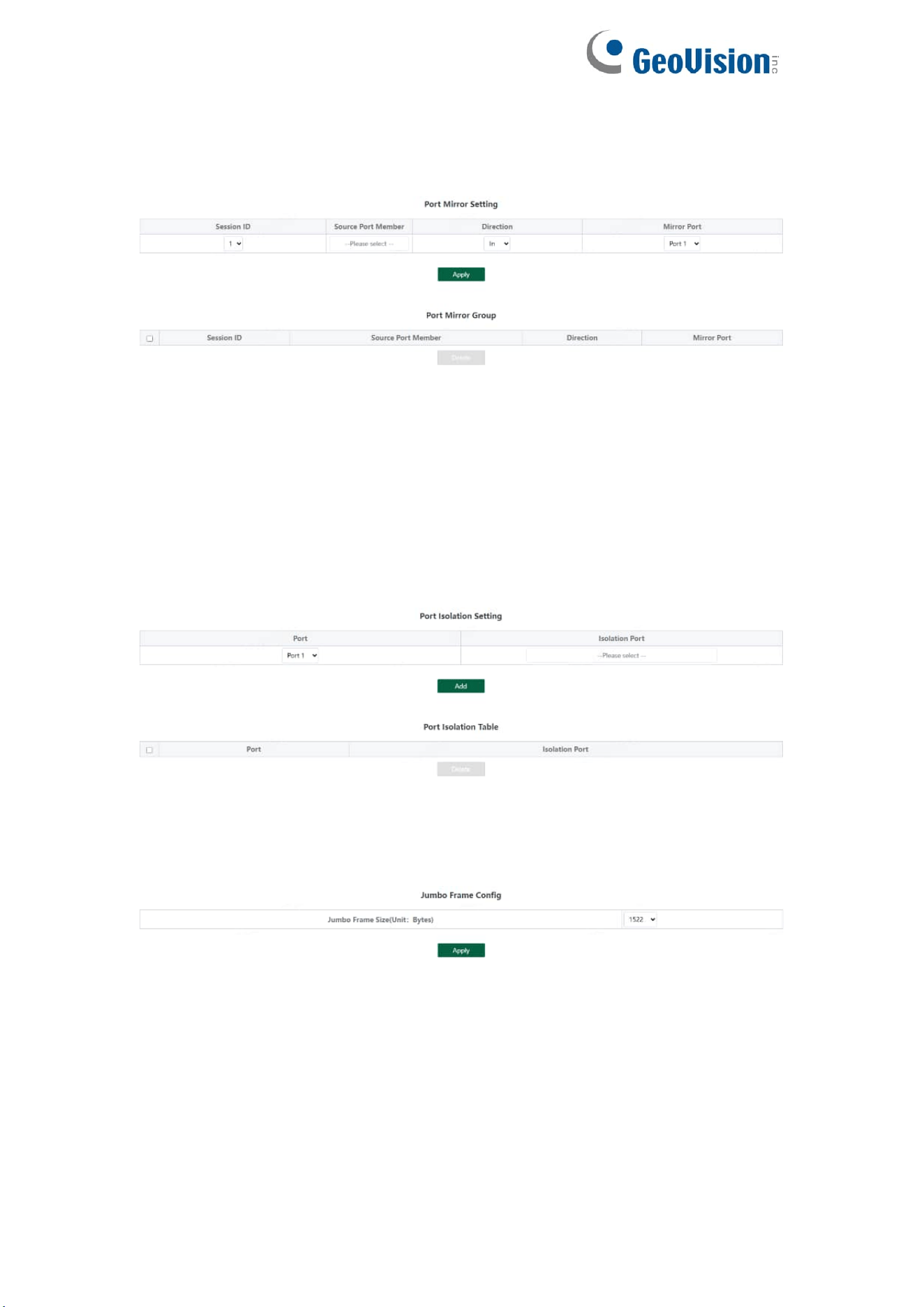
3.4.2. Port Mirroring
The input / output messages of one or more source image ports are
forwarded to the destination image port to monitor the network.
Tips:
1. Source port and destination port cannot be the same
2. Another mirror group is using the destination port
3. Supports 4 Session IDs
3.4.3. Port Isolation
Configure isolation port group
3.4.4. Jumbo Frame
Configure the size of Jumbo Frames that can be forwarded.
Tips:
1. Jumbo Frames can be configured with 1522, 1536, 1552, 9216 and 10000;
2. The default value of Jumbo Frames is 1522.
16
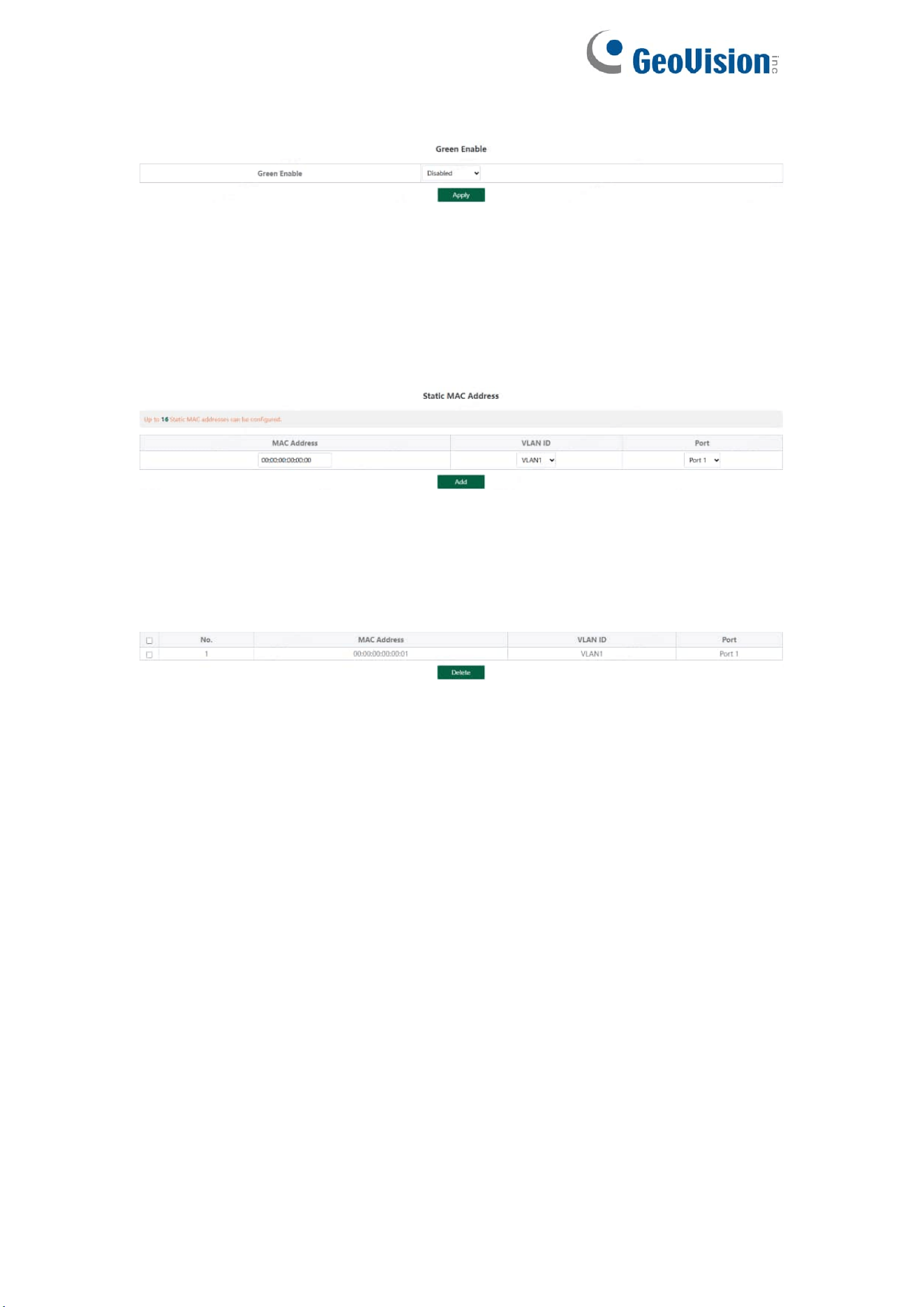
3.4.5. Green Enable
3.4.6. Static MAC
The static MAC configuration is divided into two parts.
Static MAC add:
Enter the legitimate MAC address, VLAN ID, and select the configured port
number. Click Add to add static MAC.
Static MAC deletion and display:
After adding a legal static Mac, the corresponding data will be displayed;
Check the static Mac and click Delete. After the configuration is successful,
the MAC address, VLAN and corresponding port will be unbound.
Tips:
1. Static MAC addresses maximum can be configured 16.
17
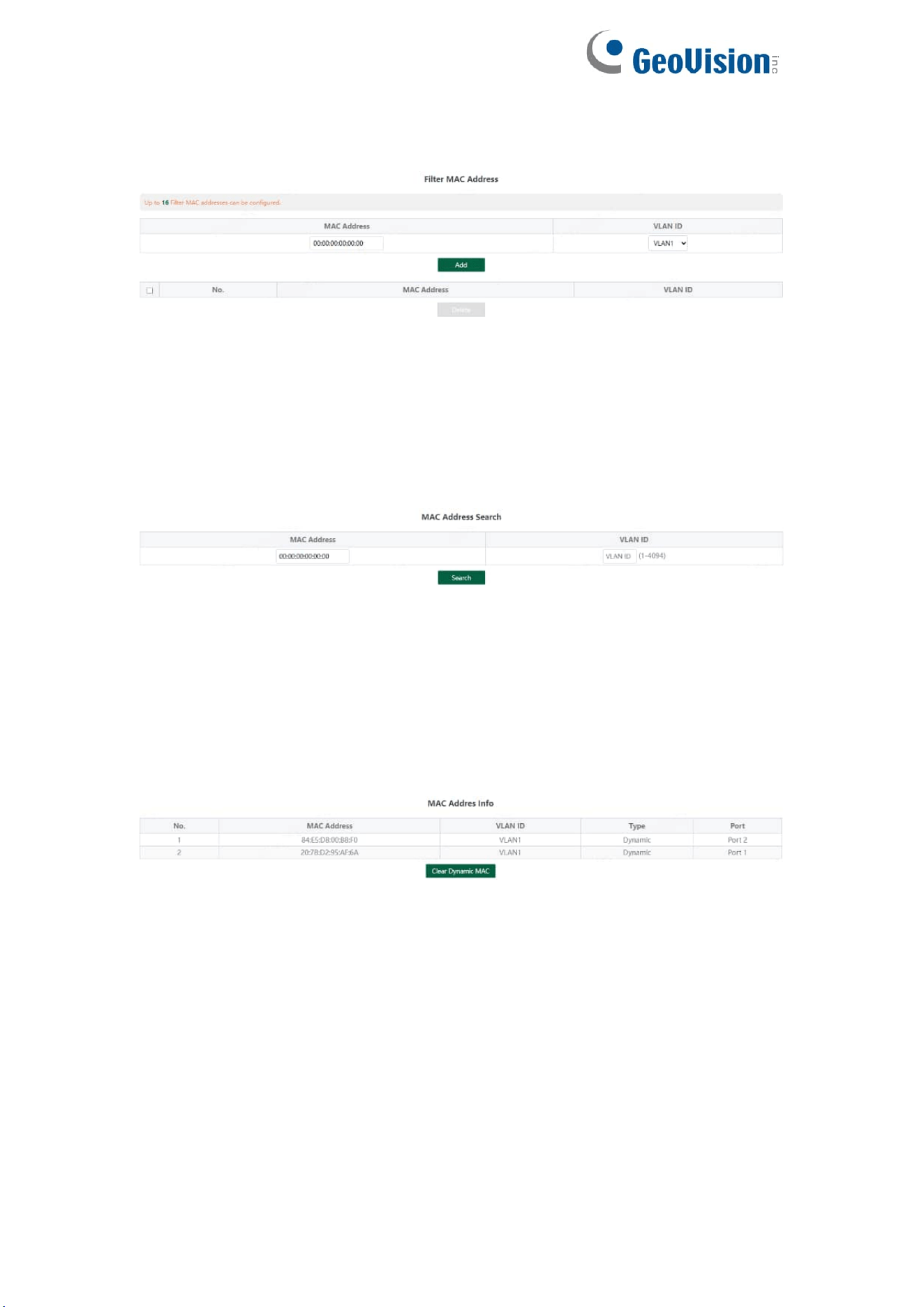
3.4.7. Filter MAC
Configure filtered MAC address
Tips:
1. Filter MAC addresses maximum can be configured 16.
3.4.8. Search MAC
Search the MAC table learned by the device (support fuzzy search?)
Tips:
1. The inquiry waiting process will interrupt the communication with the
equipment
3.4.9. MAC List
Displays the list of MAC learned by the device
Click Clear Dynamic MAC and the device will get the learning MAC list again.
Tips:
1. The display waiting process will interrupt communication with the device
18
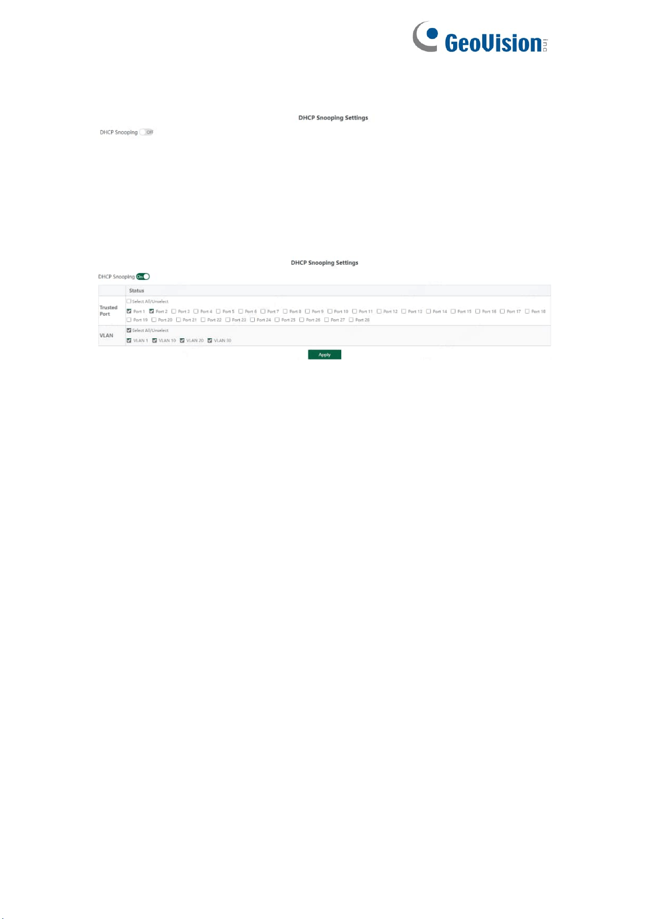
3.4.10. DHCP Snooping
Configure DHCP Snooping function, which is disabled by default.
When DHCP Snooping is enabled, you can choose to trust ports or not. As
shown in the following figure, the device sets the selected ports as trusted
ports, and if it is not selected, all ports are untrusted ports; Click Apply to set
the selected port as a trusted port and complete the configuration of DHCP
snooping.
Tips:
1. Enable DHCP snooping to filter DHCP messages. For the request message
from DHCP client, only forward it to the trust port; for the response message
from DHCP server, only forward the response message from the trust port.
2. Generally, the DHCP server port (upper connection port) is set as the trust
port.
19
3.5. VLAN Settings
Add or delete device VLAN members and port VLAN configuration
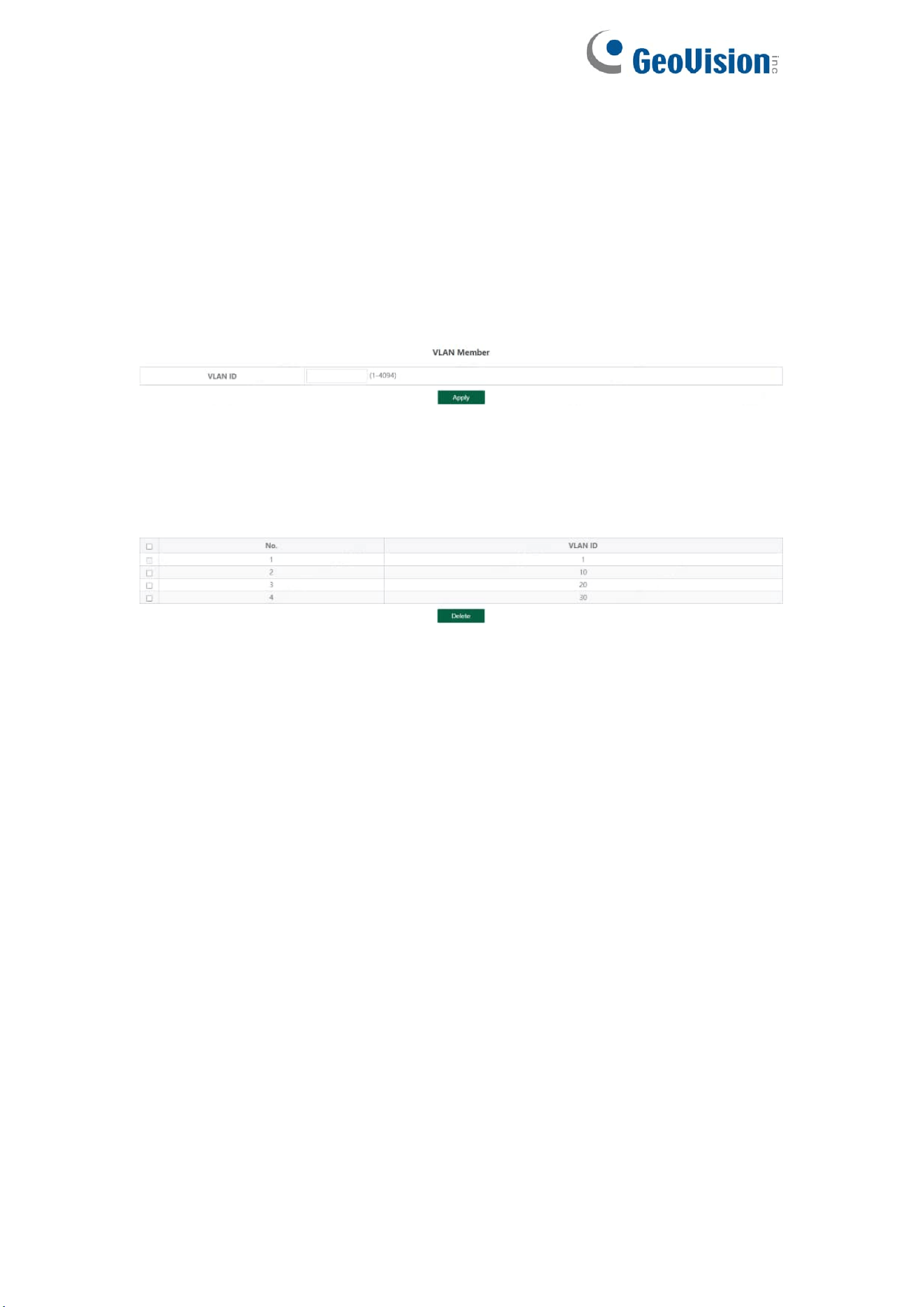
3.5.1. VLAN Member
Configuration part:
Enter a valid VLAN ID and click Apply to configure a new VLAN member;
Display part:
Displays the VLAN members newly added by the device, Select VLAN
members in the VLAN member list and click Delete to delete VLAN members
in batch
Tips:
1. Configure up to 16 VLAN members;
2. When VLAN ID is bound by port, it cannot be deleted.
20
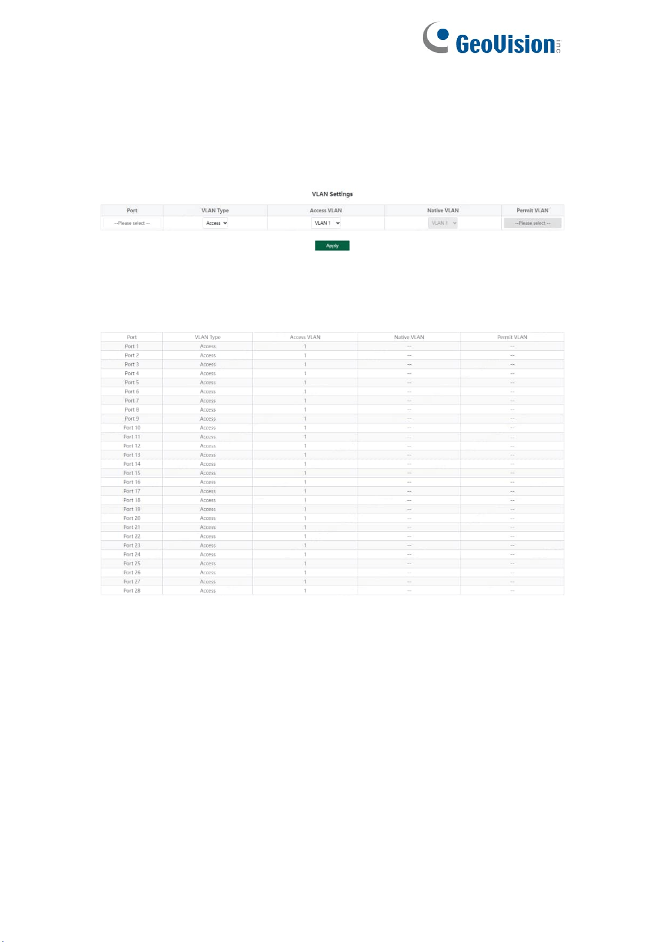
3.5.2. VLAN Settings
Port VLAN configuration is divided into two parts:
Part I: Port VLAN configuration, select port, VLAN type (access and trunk,
allow VLAN can be configured under trunk), allow VLAN and native VLAN,
and click Apply to configure and save port VLAN (Permit VLAN and Native
VLAN are selected from the VLAN members configured above);
Part II: Port VLAN list, which displays the VLAN configuration of the device
port.
Tips: the message under Native VLAN does not have VLAN tag.
21
3.6. QoS Settings
Including port rate limit and storm control functions.
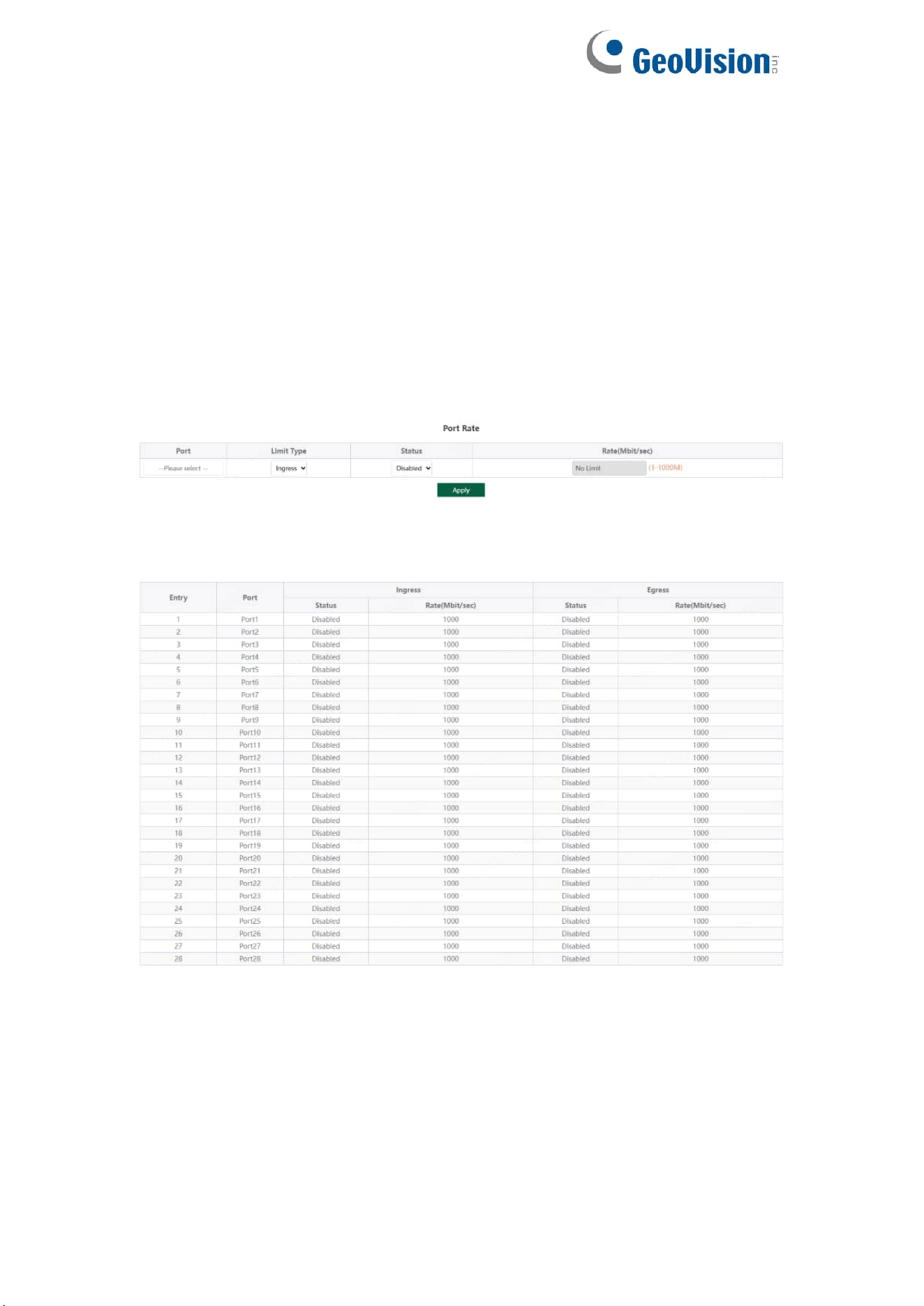
3.6.1. Port Rate
Configure the port ingress and egress rate, which is divided into two parts:
Configuration part:
Select one or more ports, select the configuration type and whether to enable
the port speed limit (enter the value of the port speed limit when it is enabled),
and click Apply to configure the port rate.
Display part: displays the ingress rate and egress rate of the device port
configuration.
Tips:
1. Rate limit range: 1-1000M
22
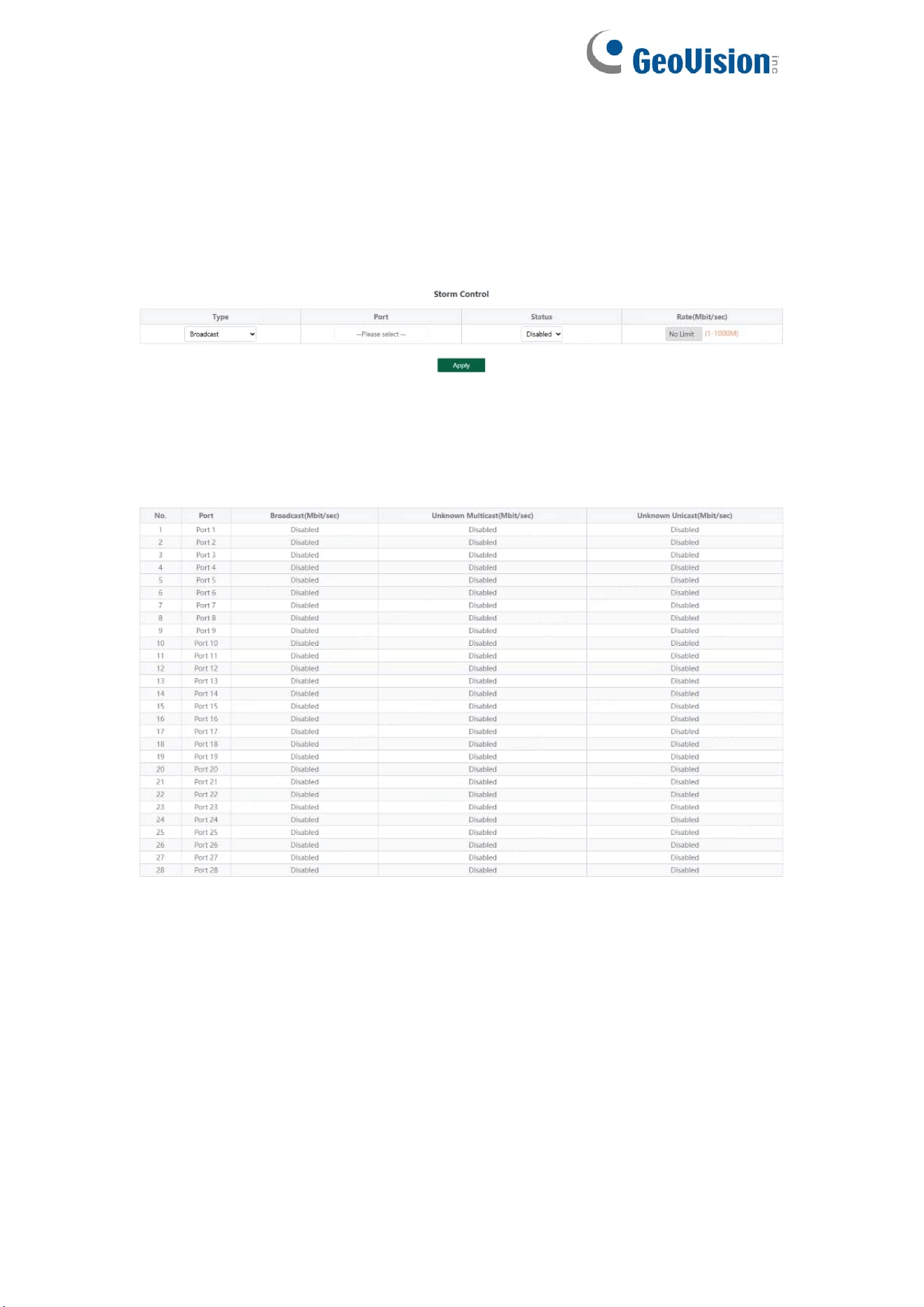
3.6.2. Storm Control
Including port storm control configuration and display:
Configuration part:
Select the configured storm control type, one or more ports and whether to
enable storm control (when enabled, enter the rate of storm control
configuration), and click Apply to configure storm control.
Display part:
Display the storm control type and corresponding rate configured by the
device port (display the corresponding control rate when it is turned on).
Tips:
1. Rate limit range: 1-1000M
23
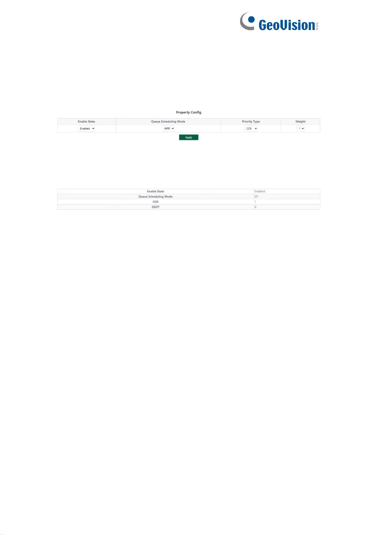
3.6.3. QoS Property
Including QoS Property configuration and display:
Configuration part:
Select the configured Enable State, Queue Scheduling Mode, Priority Type
and Weight, and click Apply configure QoS Property.
Display part:
Display the Enable State, Queue Scheduling Mode, Weighting of COS and
DSCP
Tips:
1. The QoS function is disabled by default.
2. The Queue Scheduling mode supports SP and WRR.
3. The priority type supports COS and DSCP.
4. Priority types with higher weights have higher priorities. When the weights
are the same, COS have higher priority.
24
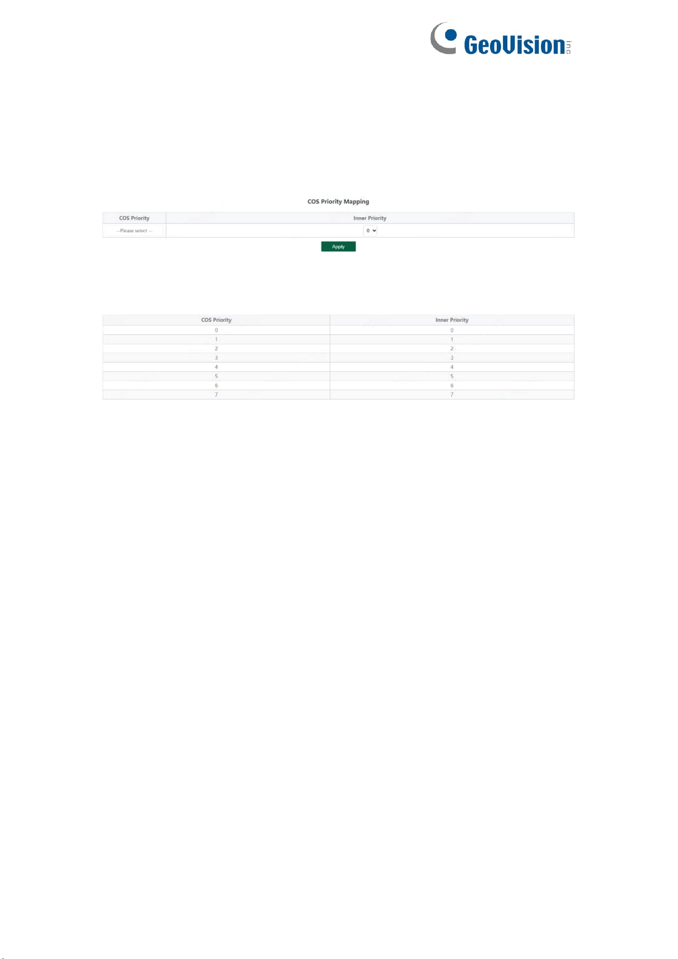
3.6.4. COS Priority Mapping
Including configuration and display:
Configuration part:
Select the configured COS Priority and Inner Priority, and click Apply
configure.
Display part:
Display the COS Priority and Inner Priority.
Tips:
1. The default COS priority corresponds to the internal priority 0-7 in turn.
25
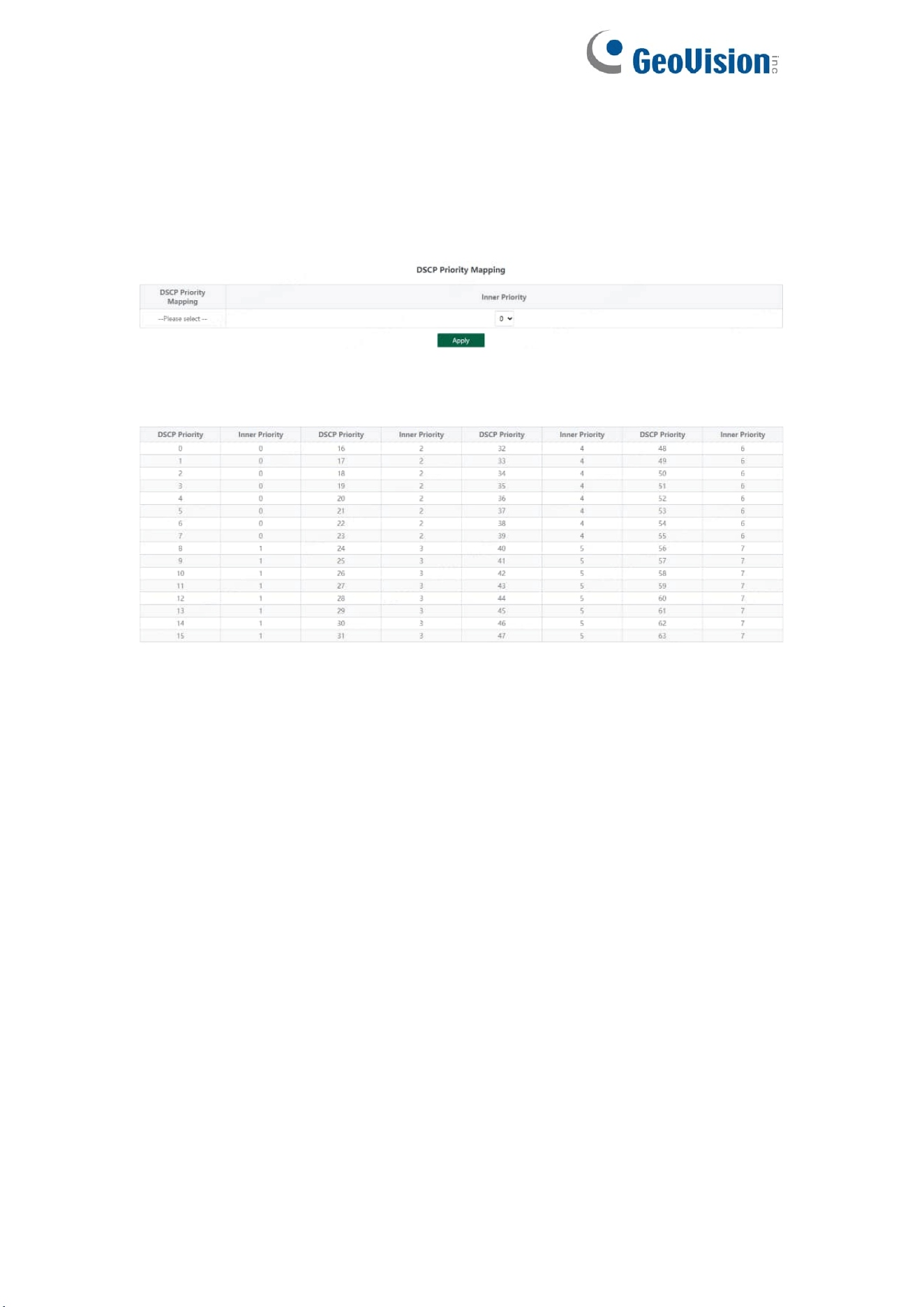
3.6.5. DSCP Priority Mapping
Including configuration and display:
Configuration part:
Select the configured DSCP Priority Mapping and Inner Priority, and click
Apply configure.
Display part:
Display the DSCP Priority Mapping and Inner Priority.
Tips:
1. Default DSCP priority 0-7 corresponds to internal priority 0, 8-15
corresponds to internal priority 1, and so on.
26
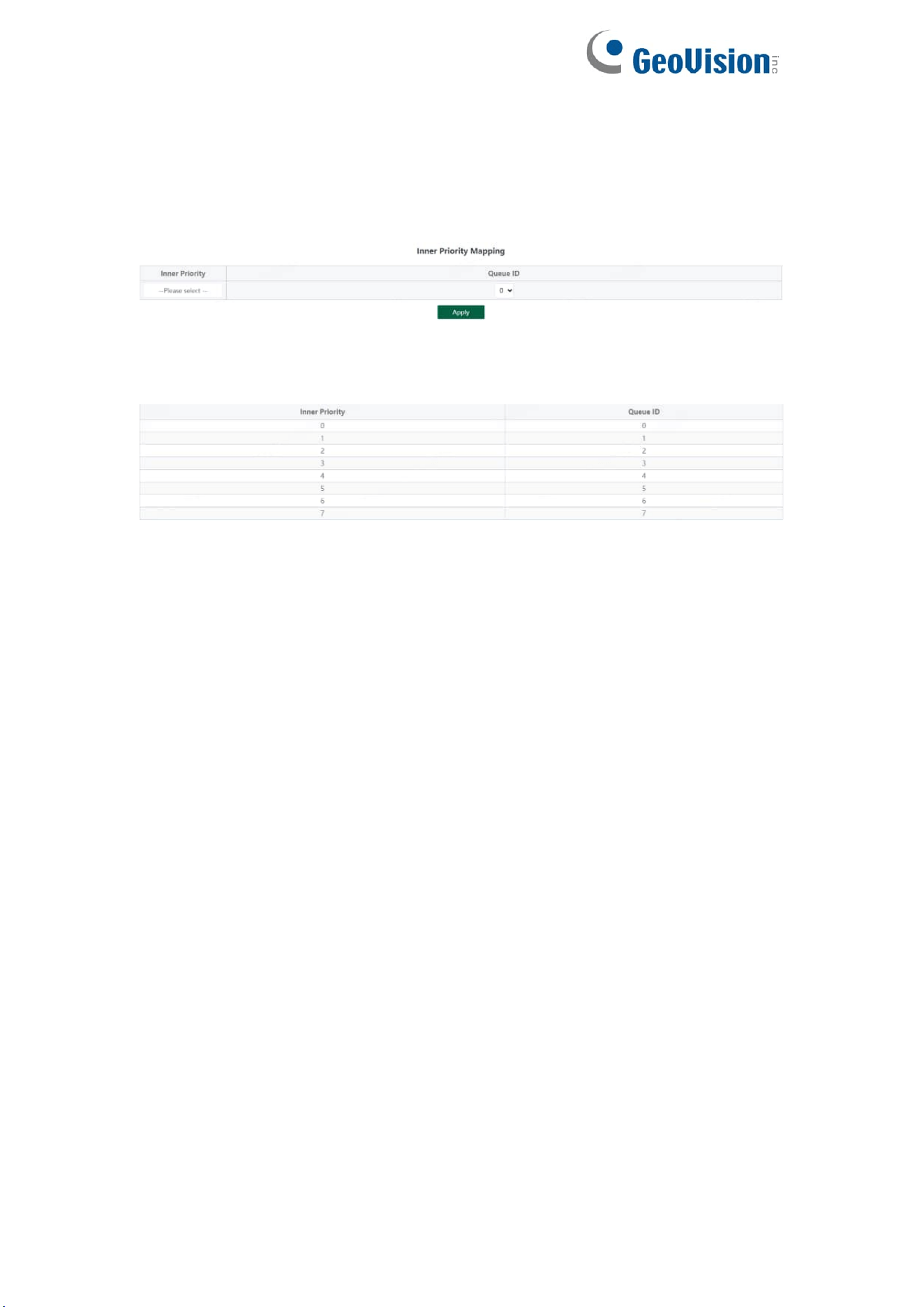
3.6.6. Inner Priority Mapping
Including configuration and display:
Configuration part:
Select the configured Inner Priority and Queue ID, and click Apply configure.
Display part:
Display the Inner Priority and Queue ID.
Tips:
1. Default internal priority 0-7 corresponds to queue ID 0-7.
27
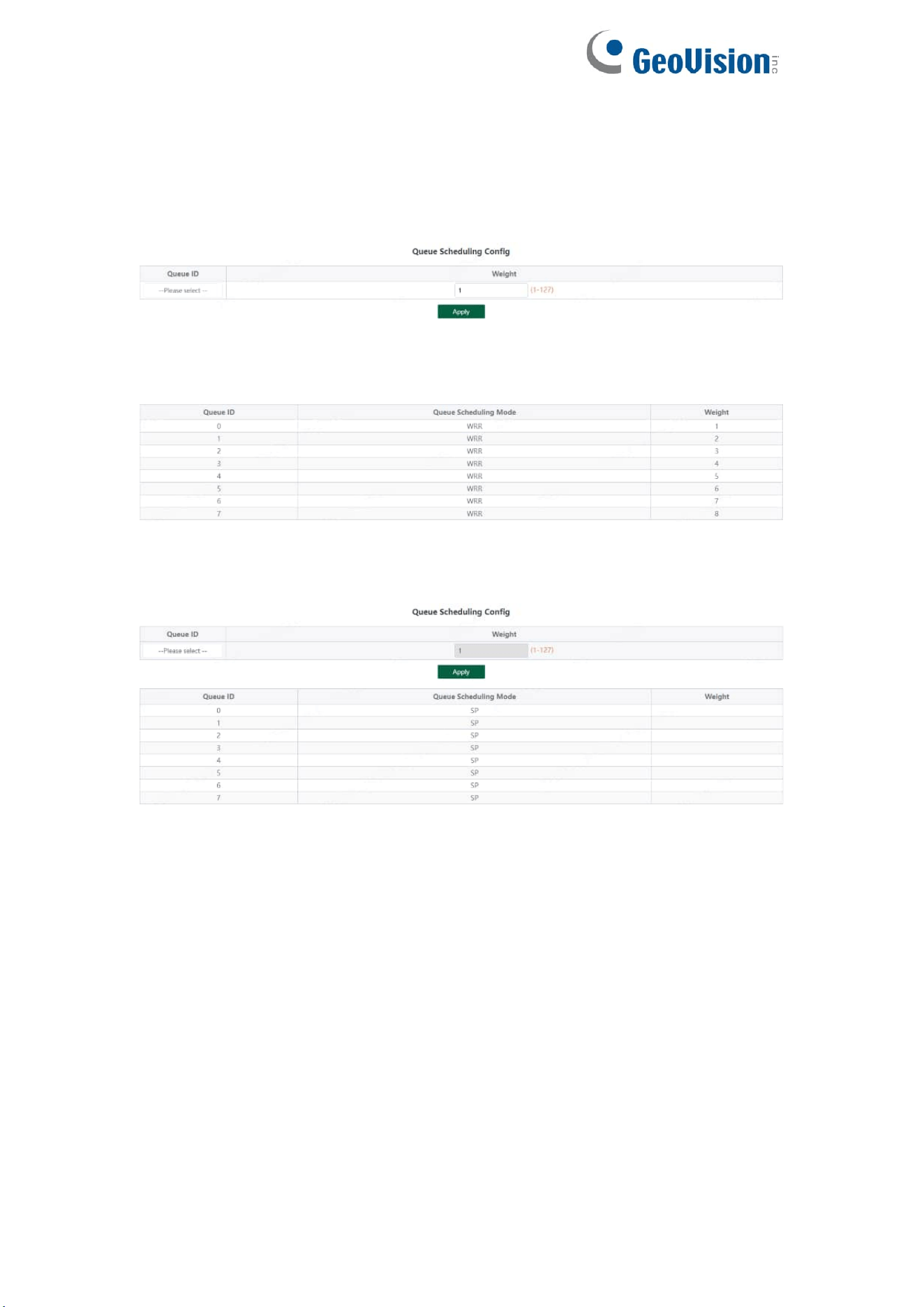
3.6.7. Queue Scheduling
Including configuration and display:
Configuration part:
Select the configured Queue ID and Weight, and click Apply configure.
Display part:
Display the Queue ID and Weight
When the queue scheduling mode is SP, the weight cannot be set. The default
weight of the eight queues is 1.
Tips:
1. When the queue scheduling mode is WRR, 0-7 of the queue ID
corresponds to 1-8 of the weight by default.
28
3.7. PoE Settings
Tips:
Some models support PoE function
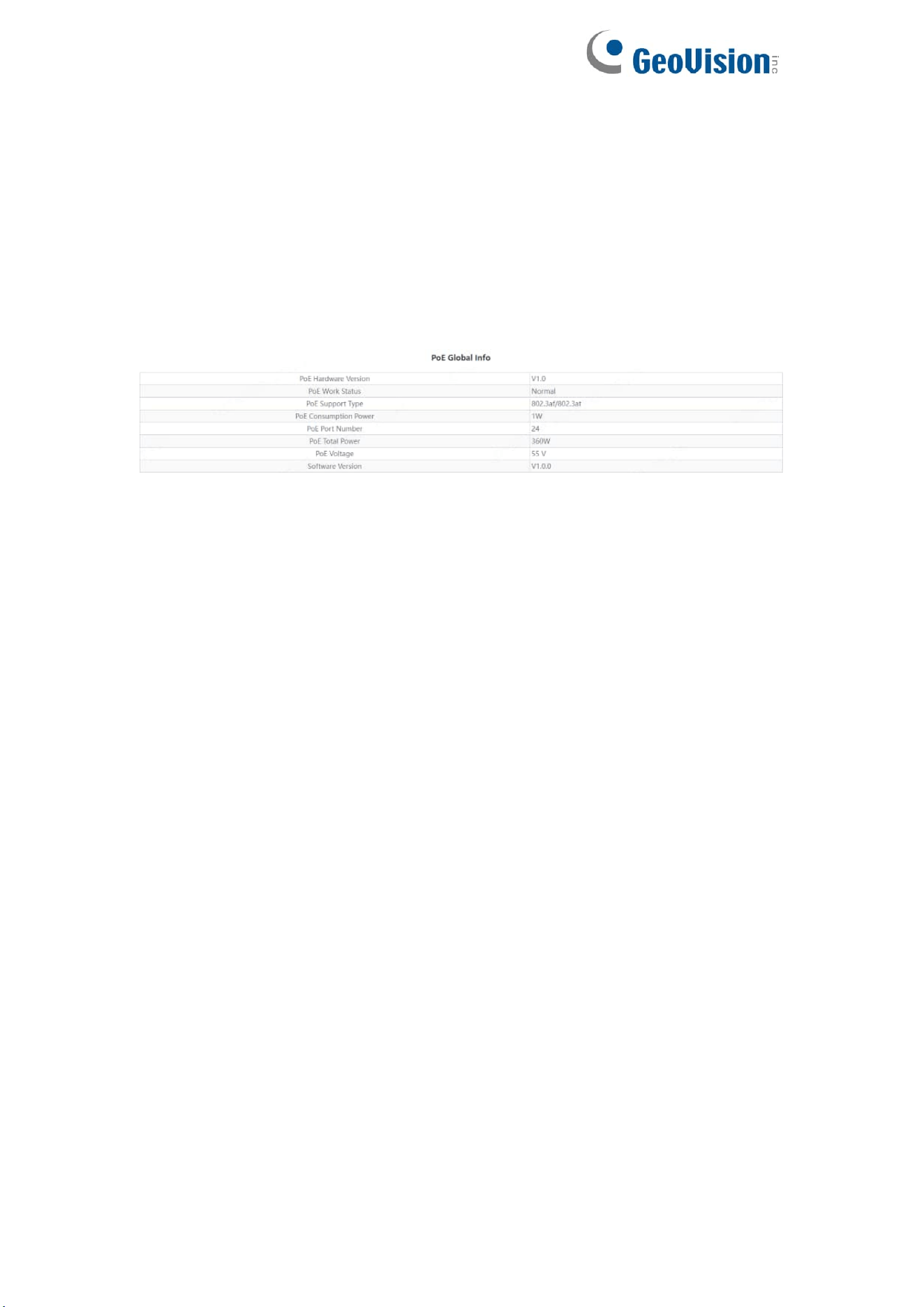
3.7.1. PoE Global Info
Displays the global information of the device Poe function
29
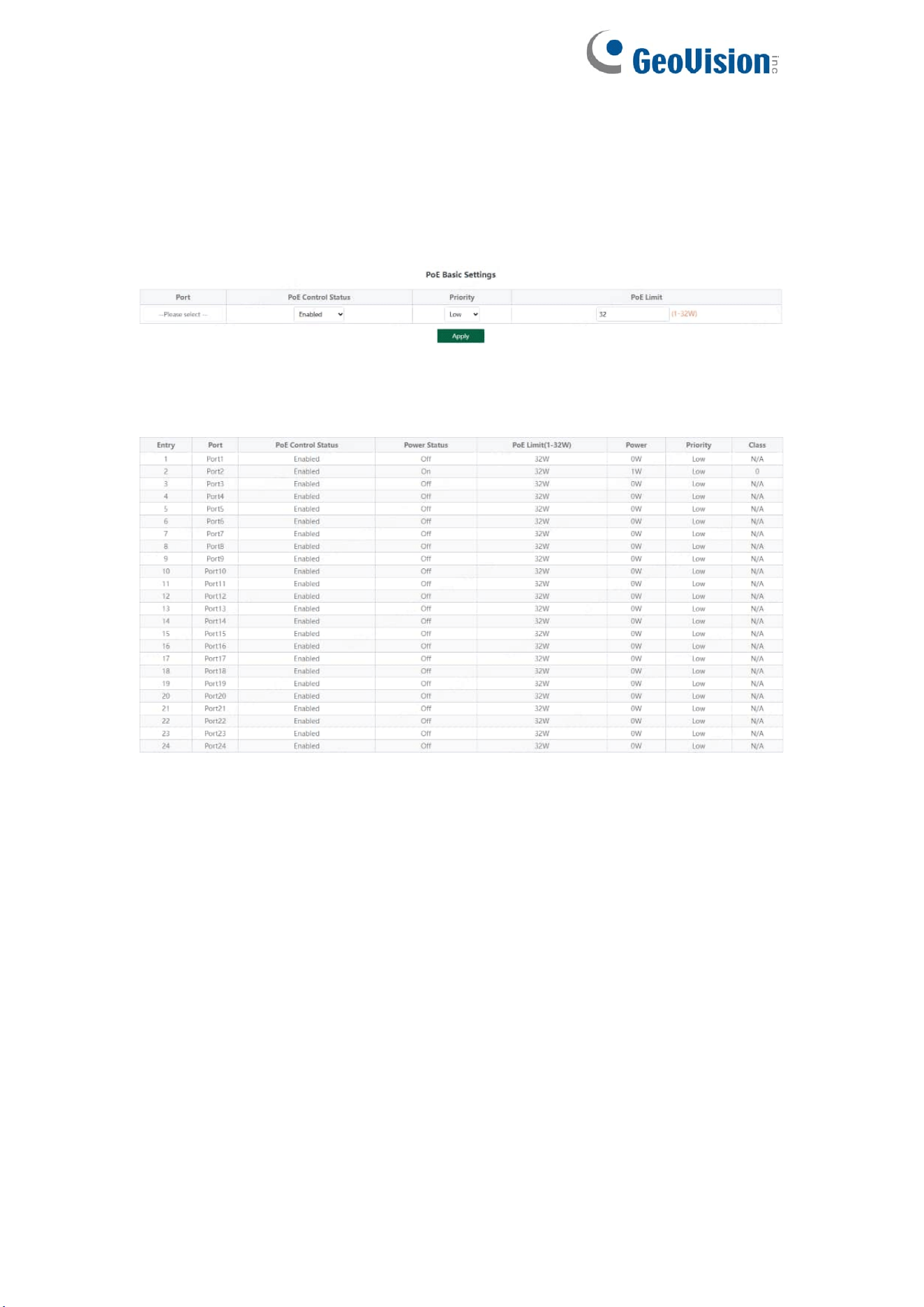
3.7.2. PoE Basic Settings
Includes port PoE configuration and display:
Configuration part:
Select the PoE power supply status, priority and limited power of the
configured port, and click Apply to configure PoE.
Display part:
Display the power of port PoE and the current power supply status;
Tips:
1. Disable port Poe. Port Poe will not be powered.
30
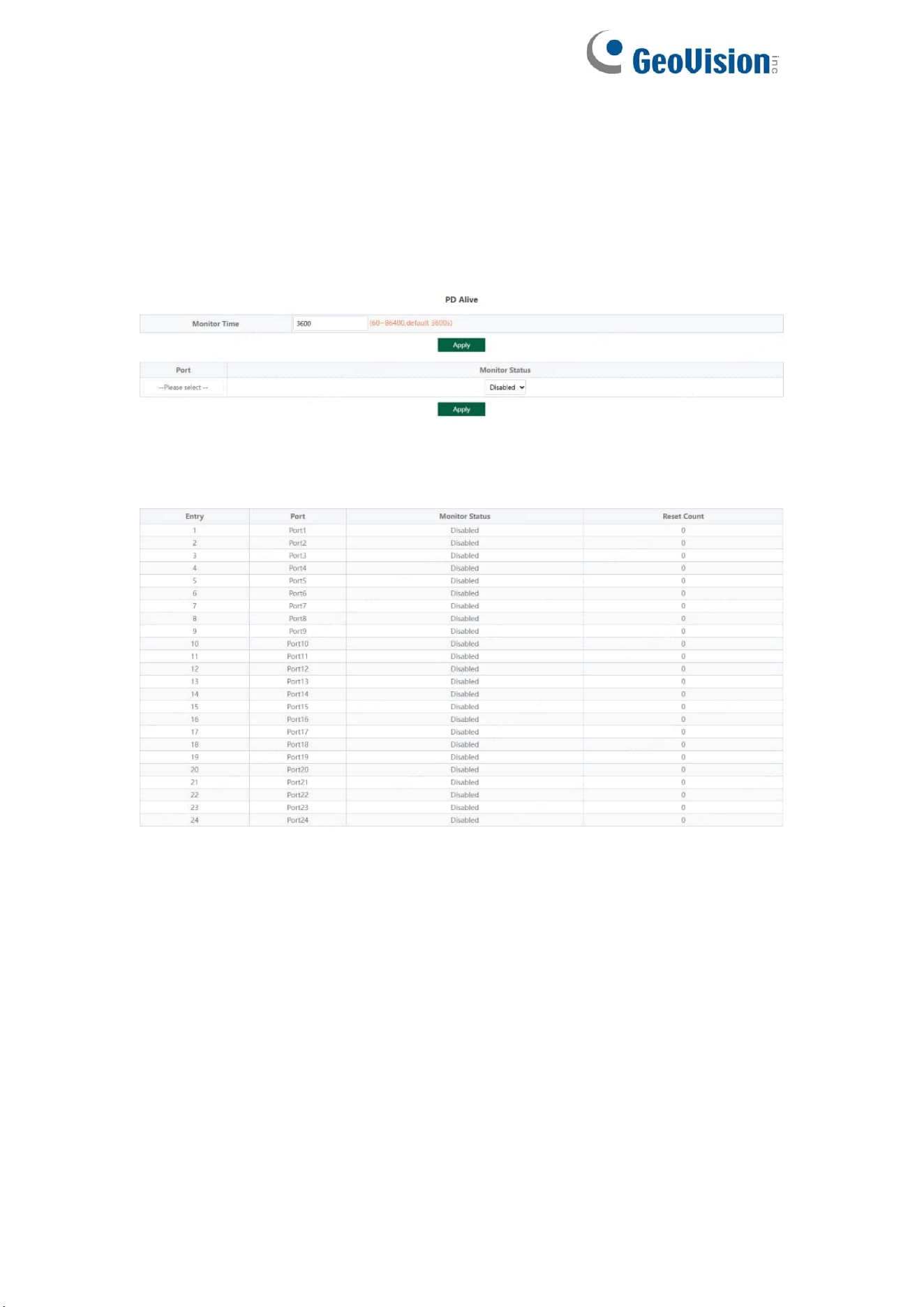
3.7.3. PD Alive
Includes PD Alive configuration and display:
Configuration part:
Configure the detection time of PD Alive (60-86400s. When no communication
is detected on the port, PoE will be restarted automatically). Click Apply to
configure PD alive.
Display part:
Displays the number of restarts of device PD Alive.
31
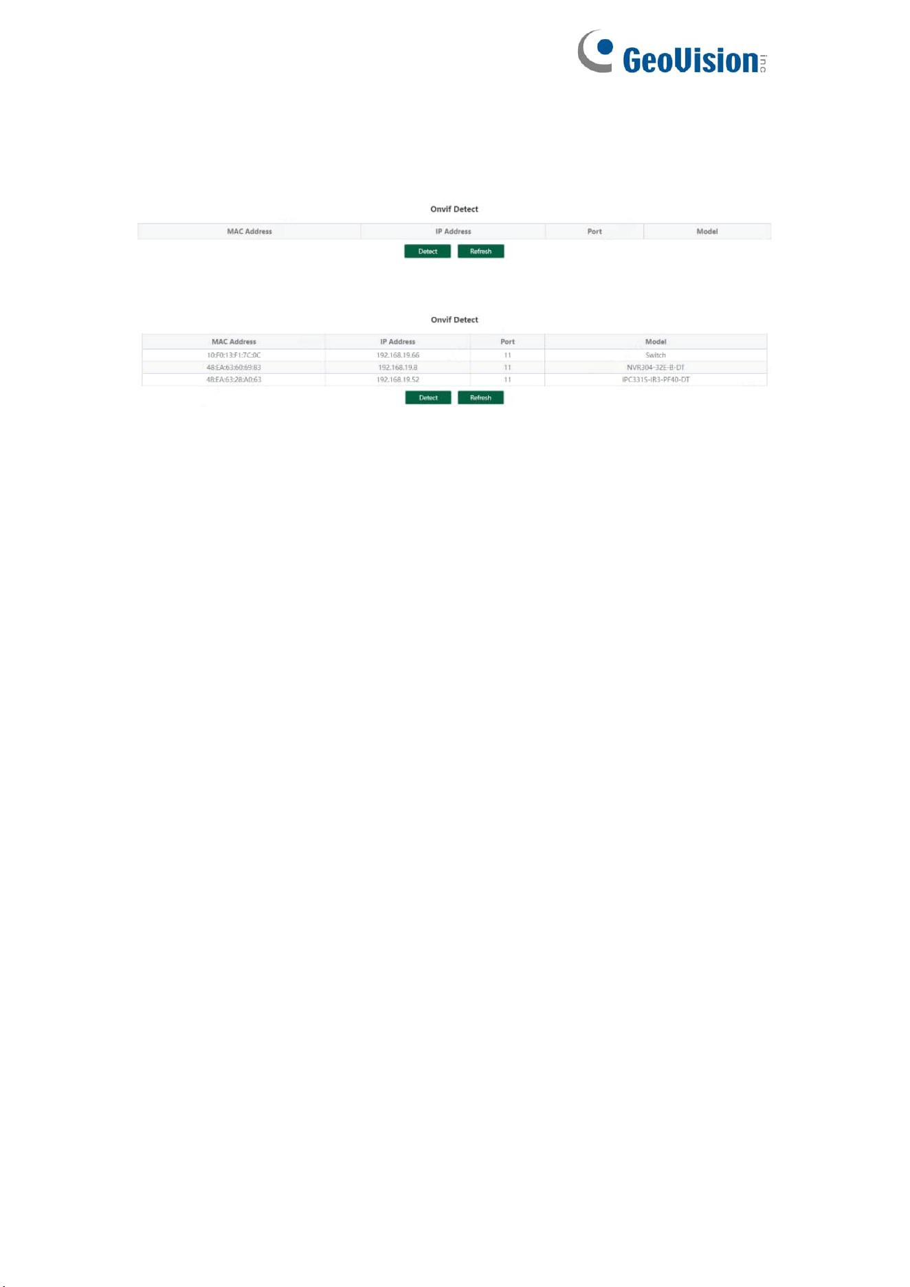
3.8. Onvif
Support Onvif protocol function to discover devices
Click《Detect》to find the device.

32
4. Frequently Asked Questions
Question 1: unable to log in to the device manager web management
interface. What should I do?
Refer to the following steps:
1) Confirm that the PC network cable is normally connected to the device port,
and the corresponding indicator flashes.
2) Before accessing the setting interface, it is recommended to set the
computer to "static IP mode" and configure it to 10.224.0.XX (e.g.
10.224.0.121, which cannot be consistent with the device configuration IP
10.XX.XX.XX (XX.XX.XX is the last two digits of the MAC address of the
current device)), subnet mask: 255.0.0.0.
3) Use the ping command to detect the connectivity between the computer
and the device.
Question 2: what if you forget your device user name and password?
How to restore the factory configuration?
If you forget the login password, long press the reset key on the panel for 5
seconds when the device is powered on, and the device will be restored to the
factory setting after restarting