
© 2025 GeoVision, Inc. All rights reserved.
Under the copyright laws, this manual may not be copied, in whole or in part,
without the written consent of GeoVision.
Every effort has been made to ensure that the information in this manual is
accurate. GeoVision, Inc. makes no expressed or implied warranty of any kind
and assumes no responsibility for errors or omissions. No liability is assumed
for incidental or consequential damages arising from the use of the information
or products contained herein. Features and specificatio
ns are subject to
change without notice.
GeoVision, Inc.
9F, No. 246, Sec. 1, Neihu Rd.,
Neihu District, Taipei, Taiwan
Tel: +886-2-8797-8377
Fax: +886-2-8797-8335
http://www.geovision.com.tw
Trademarks used in this manual: GeoVision, the GeoVision logo and GV
series products are trademarks of GeoVision, Inc. Windows is the registered
trademark of Microsoft Corporation.
March2025
Scan the following QR codes for product warranty and technical support
policy:
[Warranty] [Technical Support Policy]

Contents
Getting Started ................................................................................................. 1
Web-based Switch Configuration ..................................................................... 4
Console Port Interface ..................................................................................... 5
1.System Config............................................................................................... 6
1.1.System Homepage ............................................................................. 6
1.2.Device Info .......................................................................................... 7
1.3.IP Config ............................................................................................. 7
1.3.1.IPv4 Config .............................................................................. 7
1.3.2.IPv6 Config .............................................................................. 8
1.4.Web Config ......................................................................................... 9
1.4.1.Web Timeout ........................................................................... 9
1.4.2.HTTP ........................................................................................ 9
1.4.3.HTTPS ...................................................................................... 9
1.4.4.Security IP ............................................................................. 10
1.4.5.ACL ........................................................................................ 10
1.5.User Management ............................................................................ 11
1.5.1.User Management ................................................................. 11
1.5.2.Authentication Method ......................................................... 12
1.6.Firmware Upgrade ............................................................................ 13
1.6.1.TFTP Service ......................................................................... 13
1.6.2.FTP Service ........................................................................... 13
1.6.3.HTTP Upgrade ....................................................................... 14
1.7.Management Config ......................................................................... 14
1.7.1.TFTP ....................................................................................... 14
1.7.2.HTTP ...................................................................................... 15
1.8.NTP .................................................................................................. 15
1.8.1.NTP Config ............................................................................ 15
1.8.2.NTP Authentication Config .................................................. 16
1.9.SNTP ................................................................................................ 16
1.9.1.Server Config ........................................................................ 16
1.9.2.Time Zone Config ................................................................. 17
1.10.Device Management ....................................................................... 17
1.10.1.Device Reboot/Reset .......................................................... 17
1.10.2.System Utilization ............................................................... 17
1.10.3.View System Config ........................................................... 18
1.10.4.View Logging Buffer ........................................................... 18
1.10.5.View Logging Flash ............................................................ 18
2.Monitor Management .................................................................................. 19

2.1.SSH Config ....................................................................................... 19
2.2.Telnet Config ..................................................................................... 19
2.3.Port Statistics .................................................................................... 20
2.4.DDMI Status ..................................................................................... 21
2.5.Ping .................................................................................................. 22
2.6.Traceroute ........................................................................................ 22
2.7.Cable Diagnostics ............................................................................. 23
2.8.SNMP Config .................................................................................... 23
2.8.1.Global Config ........................................................................ 23
2.8.2.User Config ........................................................................... 24
2.8.3.Group Config ........................................................................ 25
2.8.4.Community Config ................................................................ 25
2.8.5.Trap Config ............................................................................ 26
2.8.6.View Config ........................................................................... 26
2.8.7.Security IP Config ................................................................. 27
2.8.8.SNMP Statistics .................................................................... 27
2.9.Onvif Config ...................................................................................... 28
2.9.1.Server Config ........................................................................ 28
2.9.2.Detect Config ........................................................................ 28
2.10.Loopback Detection ........................................................................ 28
2.10.1.Port Mode ............................................................................ 28
2.10.2.VLAN Loopback .................................................................. 29
2.10.3.Interval Time ........................................................................ 30
2.10.4.Recovery Timeout ............................................................... 30
2.11.LLDP Config .................................................................................... 31
2.11.1.Global Config ...................................................................... 31
2.11.2.Port Config .......................................................................... 32
2.11.3.TLV Config ........................................................................... 33
2.11.4.Neighbor Info....................................................................... 33
3.Switch Config .............................................................................................. 34
3.1.Port Config ........................................................................................ 34
3.1.1.Port Config ............................................................................ 34
3.1.2.Port Combo Mode(Specific) ................................................. 36
3.1.3.Port 10G Mode(Specific) ...................................................... 36
3.2.Port Mirror ......................................................................................... 37
3.3.Port Isolate ........................................................................................ 38
3.4.Port Channel ..................................................................................... 38
3.4.1.Port Channel Group .............................................................. 38
3.4.2.LACP ...................................................................................... 40
3.5.Jumbo Frame .................................................................................... 40
3.6.Port Rate ........................................................................................... 41
3.7.Storm Control .................................................................................... 42

3.8.MAC Address Config ........................................................................ 43
3.8.1.Static MAC ............................................................................. 43
3.8.2.Black Hole MAC .................................................................... 43
3.8.3.Aging-time ............................................................................. 44
3.8.4.MAC Address List ................................................................. 45
3.9.AM .................................................................................................... 45
3.10.AAA ................................................................................................ 46
3.10.1.Radius .................................................................................. 46
3.10.2.Radius Accounting ............................................................. 47
3.10.3.Tacacs .................................................................................. 48
4.VLAN Config ............................................................................................... 50
4.1.VLAN Config ..................................................................................... 50
4.1.1.VLAN ID ................................................................................. 50
4.1.2.Show VLAN ........................................................................... 50
4.1.3.Port Config ............................................................................ 51
4.2.GVRP Config .................................................................................... 52
4.2.1.GVRP Config ......................................................................... 52
4.2.2.GVRP Port ............................................................................. 52
4.3.QINQ................................................................................................. 53
4.3.1.Enable Dot1q Tunnel ............................................................ 53
4.3.2.Dot1q Tunnel TPID ................................................................ 53
4.4.Protocol VLAN .................................................................................. 54
4.5.Voice VLAN ....................................................................................... 54
4.5.1.VLAN Config ......................................................................... 54
4.5.2.Port Config ............................................................................ 55
4.6.MAC VLAN ....................................................................................... 56
4.6.1.VLAN Config ......................................................................... 56
4.6.2.VLAN Member ....................................................................... 56
4.6.3.Port Config ............................................................................ 57
5.DHCP Config .............................................................................................. 57
5.1.DHCP Server .................................................................................... 57
5.1.1.Global Config ........................................................................ 57
5.1.2.Create Address Pool ............................................................ 58
5.1.3.Dynamic Pool ........................................................................ 58
5.1.4.Manual Pool .......................................................................... 60
5.1.5.Default Gateway .................................................................... 61
5.1.6.DNS Server ............................................................................ 62
5.1.7.Excluded Address ................................................................ 62
5.1.8.Packet Statistics ................................................................... 63
5.1.9.Client List .............................................................................. 64
5.2.DHCP Snooping ............................................................................... 64
5.2.1.Global Config ........................................................................ 64

5.2.2.VLAN Config ......................................................................... 65
5.2.3.Static User Binding ............................................................... 66
5.2.4.Helper-server Config ............................................................ 67
5.2.5.Port Binding .......................................................................... 68
5.2.6.Trust Port ............................................................................... 69
5.3.DHCP Relay Config .......................................................................... 69
5.3.1.DHCP Relay Config ............................................................... 69
6.ACL Config .................................................................................................. 70
6.1.Time Range Config ........................................................................... 70
6.2.IP ACL ............................................................................................... 71
6.2.1.IP Standard ACL.................................................................... 71
6.2.2.IP Extended ACL ................................................................... 72
6.3.MAC ACL .......................................................................................... 73
6.3.1.MAC Standard ACL ............................................................... 73
6.3.2.MAC Extended ACL .............................................................. 74
6.4.MAC-IP Extended ACL ..................................................................... 75
6.5.ACL Binding ...................................................................................... 77
6.5.1.Binding Port .......................................................................... 77
6.5.2.Binding Vlan .......................................................................... 77
7.Ring Network .............................................................................................. 78
7.1.Spanning-tree ................................................................................... 78
7.1.1.Global Properties .................................................................. 78
7.1.2.Instance Mapping ................................................................. 80
7.1.3.Instance Properties .............................................................. 81
7.1.4.Port Config ............................................................................ 81
7.1.5.Port Instance ......................................................................... 82
7.1.6.Status ..................................................................................... 83
7.2.ERPS ................................................................................................ 84
7.2.1.ERPS Ring Config ................................................................. 84
7.2.2.ERPS Instance Config .......................................................... 86
7.2.3.View ERPS Statistics ............................................................ 88
8.Route Config ............................................................................................... 89
8.1.Static Route ...................................................................................... 89
8.2.Routing Table .................................................................................... 89
9.Multicast Manage ........................................................................................ 90
9.1.IGMP Snooping Config ..................................................................... 90
9.1.1.Basic Config .......................................................................... 90
9.1.2.Static Router Port ................................................................. 91
9.1.3.VLAN Config ......................................................................... 91
9.1.4.Querier Config....................................................................... 92
9.1.5.Multicast Table ...................................................................... 93
9.2.MLD Snooping Config ....................................................................... 94

9.2.1.Basic Config .......................................................................... 94
9.2.2.Static Router Port ................................................................. 94
9.2.3.VLAN Config ......................................................................... 95
9.2.4.Querier Config....................................................................... 96
9.2.5.Multicast Table ...................................................................... 97
10.QoS Config ............................................................................................... 97
10.1.Port Config ...................................................................................... 97
10.1.1.Trust Config ........................................................................ 97
10.1.2.Weight Config ..................................................................... 98
10.1.3.CoS-To-IntP Config ........................................................... 100
10.1.4.DSCP-To-IntP Config ........................................................ 101
10.1.5.Policy Config ..................................................................... 101
10.2.Class-Map Config ......................................................................... 102
10.2.1.Class-Map Config ............................................................. 102
10.2.2.Class-Map Rule Config ..................................................... 103
10.3.Policy-Map Config ......................................................................... 106
10.3.1.Policy Name Config .......................................................... 106
10.3.2.Policy Class Config .......................................................... 107
10.3.3.Policy Mark Config ........................................................... 108
10.3.4.Policy Bandwidth .............................................................. 109
10.3.5.Policy VLAN ...................................................................... 109
11.PoE Config .............................................................................................. 110
11.1.PoE Global Config......................................................................... 110
11.2.PoE Port Config ............................................................................ 111
11.3.PD Alive ........................................................................................ 112
11.4.PoE Schedule ............................................................................... 112
1
⚫ Getting Started
This section introduces the web-based configuration utility, and covers the
following topics:
• Powering on the device
• Connecting to the network
• Starting the web-based configuration utility
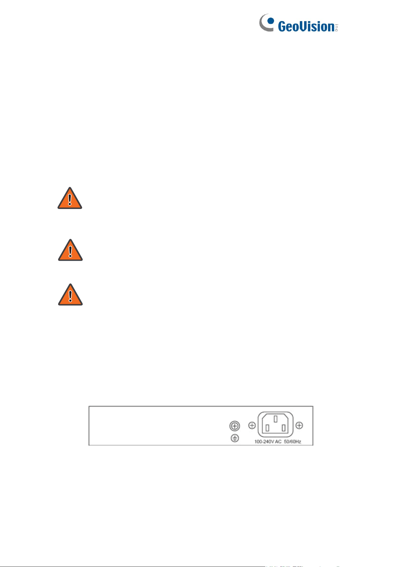
⚫ Power
Connecting to Power
Power down and disconnect the power cord before servicing or wiring a
switch.
Do not disconnect modules or cabling unless the power is first switched
off. The device only supports the voltage outlined in the type plate. Do
not use any other power components except those specifically
designated for the switch.
Disconnect the power cord before installation or cable wiring.
The switch is powered by the AC 100-240 V 50/60Hz internal
high-performance power supply. It is recommended to connect the switch with
a single-phase three-wire power source with a neutral outlet, or a
multifunctional computer professional source.
Connect the AC power connector on the back panel of the switch to the
external power source with the included power cord, and check the power LED
is on.
Rear View AC Power Socket

2
⚫ Connecting to the Network
To connect the switch to the network:
1. Connect an Ethernet cable to the Ethernet port of a computer
2. Connect the other end of the Ethernet cable to one of the numbered
Ethernet ports of the switch. The LED of the port lights if the device connected
is active.
3. Repeat Step 1 and Step 2 for each device to connect to the switch.
We strongly recommend using CAT-5E or better cable to connect
network devices. When connecting network devices, do not exceed
the maximum cabling distance of 100 meters (328 feet). It can take up
to one minute for attached devices or the LAN to be operational after it
is connected. This is normal behavior.
Connect the switch to end nodes using a standard Cat 5/5e Ethernet cable
(UTP/STP) to connect the switch to end nodes as shown in the illustration
below.
Switch ports will automatically adjust to the characteristics (MDI/MDI-X, speed,
duplex) of the device to which the switch is connected.
⚫ Starting the Web-based Configuration Utility
This section describes how to navigate the web-based switch configuration
utility. Be sure to disable any pop-up blocker.
Browser Restrictions
• If you are using older versions of Internet Explorer, you cannot directly use
an IPv6 address to access the device. You can, however, use the DNS
(Domain Name System) server to create a domain name that contains the
IPv6 address, and then use that domain name in the address bar in place of
the IPv6 address.
• If you have multiple IPv6 interfaces on your management station, use the
IPv6 global address instead of the IPv6 link local address to access the device
from your browser.
Launching the Configuration Utility
To open the web-based configuration utility:
1. Open a Web browser.
2. Enter the IP address of the device you are configuring in the address bar
on the browser (factory default IP address is 192.168.0.250) and then press
Enter.

3
When the device is using the factory default IP address, its power LED
flashes continuously. When the device is using a DHCP assigned IP
address or an administrator-configured static IP address, the power
LED is lit a solid color. Your computer’s IP address must be in the
same subnet as the switch. For example, if the switch is using the
factory default IP address, your computer’s IP address can be in the
following range: 192.168.0.x (whereas x is a number from 0 to 254).
After a successful connection, the login window displays.
Login Window
⚫ Logging In
The default username is admin and the default password is admin. The first
time that you log in with the default username and password, you are required
to enter a new password.
To log in to the device configuration utility:
1. Enter the default user ID (admin) and the default password (admin).
2. If this is the first time that you logged on with the default user ID (admin)
and the default password (admin) it is recommended that you change your
password immediately.
4
When the login attempt is successful, the System Information window displays.
System Information
If you entered an incorrect username or password, an error message appears
and the Login page remains displayed on the window. If you are having
problems logging in, please see the Launching the Configuration Utility section
in the Administration Guide for additional information.
⚫ Logging Out
By default, the application logs out after ten minutes of inactivity.
To logout, click Logout in the top right corner of any page. The system logs out
of the device.
When a timeout occurs or you intentionally log out of the system, a message
appears and the Login page appears, with a message indicating the
logged-out state. After you log in, the application returns to the initial page.
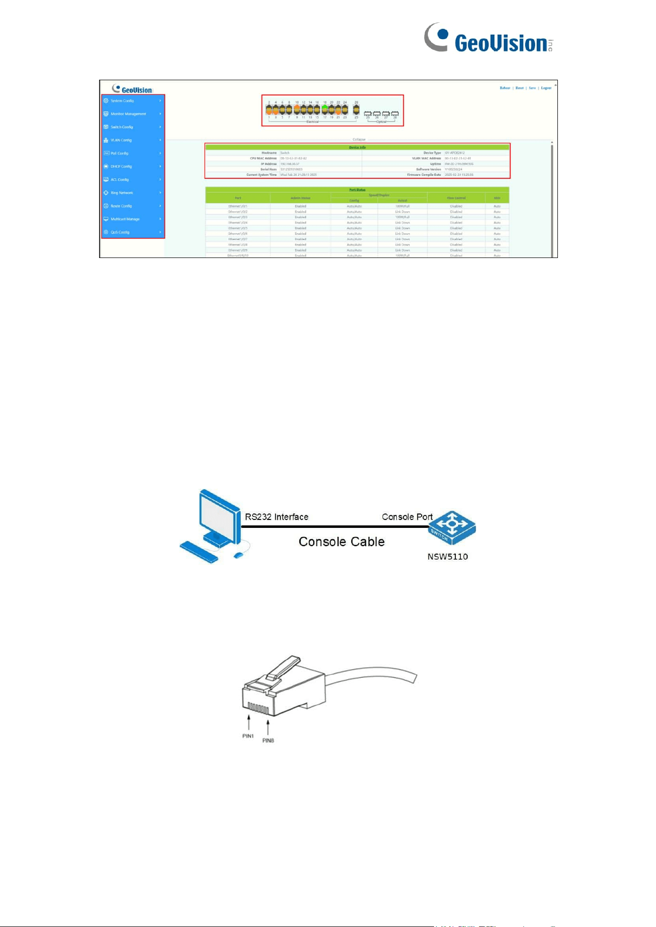
Web-based Switch Configuration
The smart switch software provides rich Layer 2 functionality for switches in
your networks. This chapter describes how to use the web-based
management interface (Web UI) to configure the switch’s features.
For the purposes of this manual, the user interface is separated into four
sections, as shown in the following figure:
5
Console Port Interface
The PoE smart switch has a monitor port (Console port). Rate 9600bps,
standard RJ45 plug.
Use a dedicated monitoring cable to lead the port to the PC serial port
connection, as follows:
The RJ45 connector used by the Console port is shown in the figure below,
and the RJ45 plug corresponds to the RJ45 socket, from left to right numbered
from 1 to 8.
This cable is used to connect the console port of the switch to the external
monitoring terminal. One end of the RJ45 eight-pin plug, the other end is a
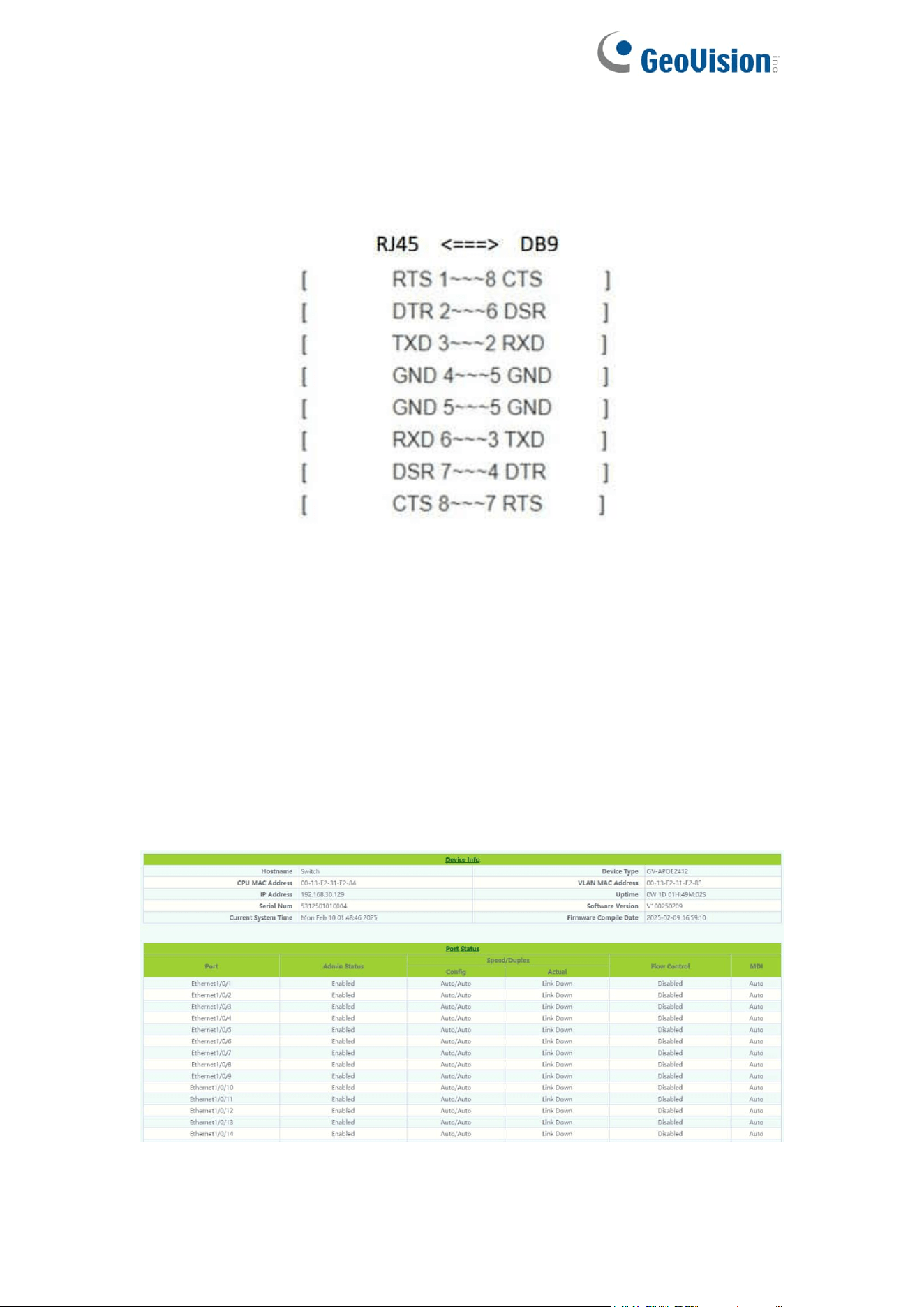
6
25-hole plug(DB25) and 9-hole plug(DB9), RJ45 head into the switch’s
console port socket, DB25 and DB9 can be used according to the
requirements of the terminal serial port, the cable internal connection
schematic as follows:
1.System Config
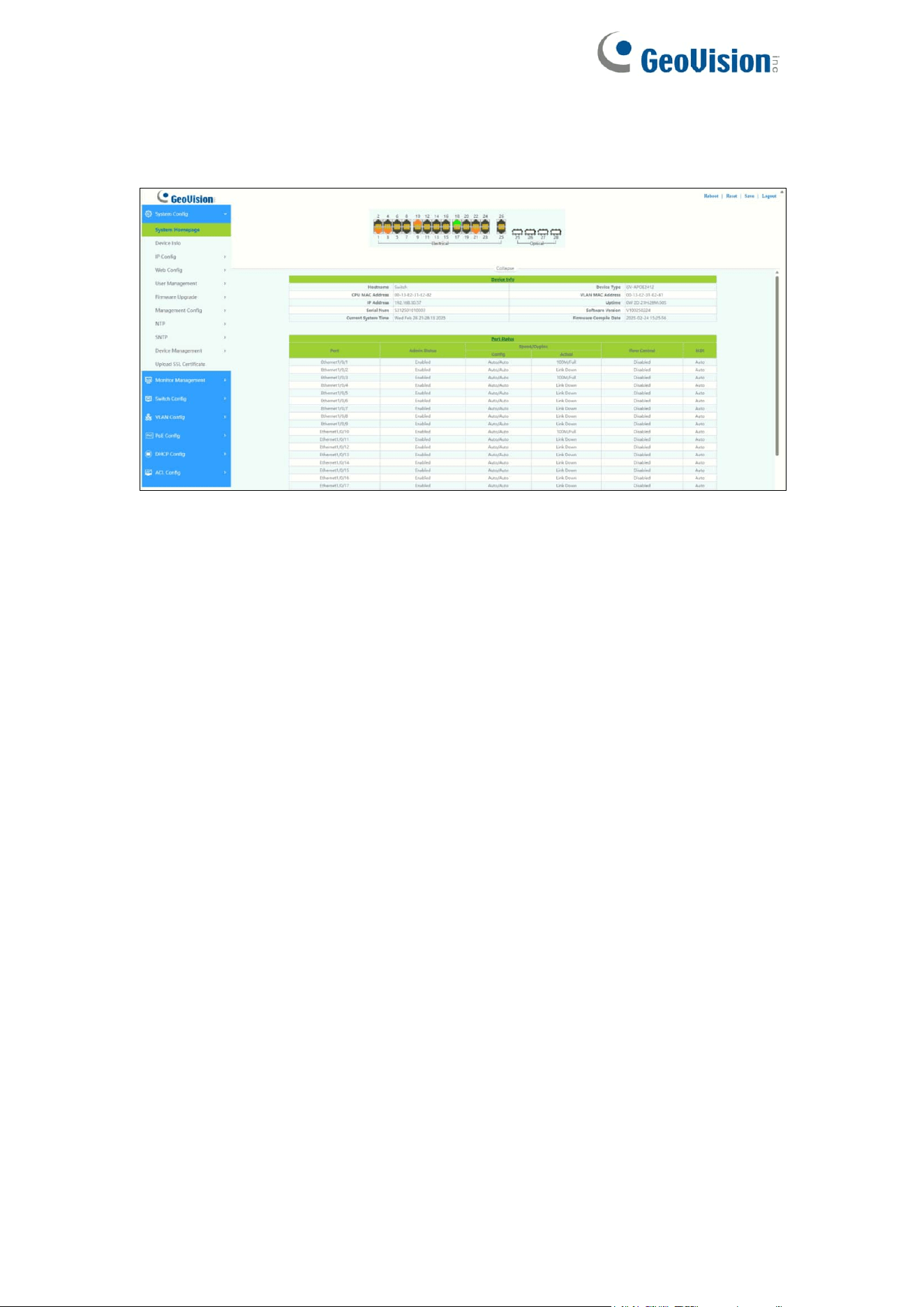
1.1.System Homepage
The system homepage contains Device Info and Port Status
Click on Device Info or Port Status to enter the corresponding page.
7
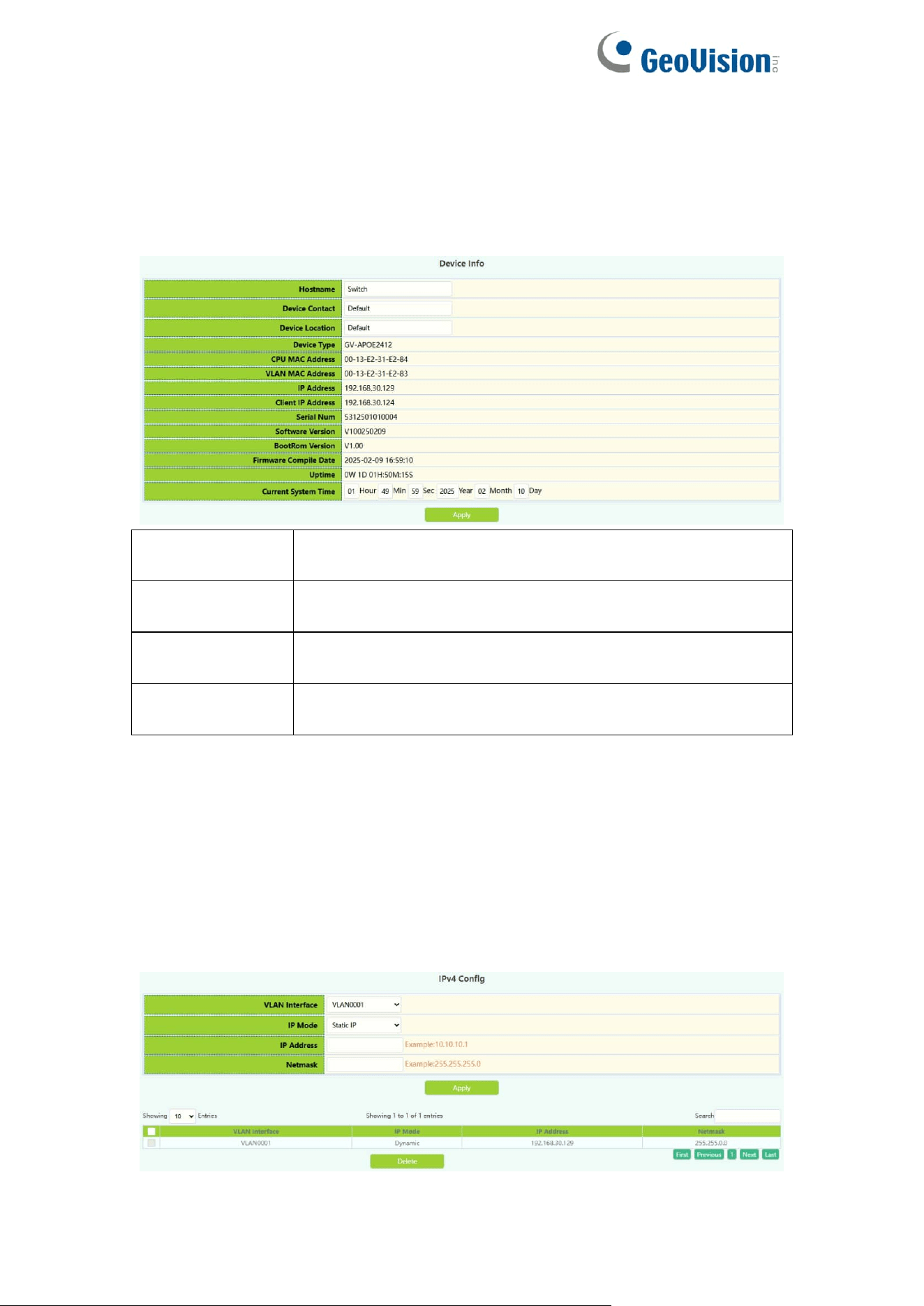
1.2.Device Info
The Device Info page allows you to view device information and also set the
Hostname, Device Contact, Device Location of the device and the Current
System Time.
Hostname
Fill in the new Hostname of the switch to be changed,
1-64 characters
Device Contact
Fill in the new Device Contact of the switch to be
changed, 0-255 characters
Device Location
Fill in the new Device Location of the switch to be
changed, 0-255 characters
Current System
Time
Manually changing the current system time, When the
switch restart will invalidate.
1.3.IP Config
1.3.1.IPv4 Config
The page can be used to configure IP address and subnet mask for the VLAN
interface.
To display the “IPv4 Config” page,click System Config ->IP Config->IPv4
Config,click "Apply" to configure.
8
VLAN Interface
VLAN ID of layer 3 interface
created
IP Mode
Static IP:User self configuration
Dynamic : dhcp-client Automatic
acquisition
IP Address
IP Address, e.g. A.B.C.D
Netmask
Netmask:for
example :255.255.255.0
Operation
Action: Apply/Delete
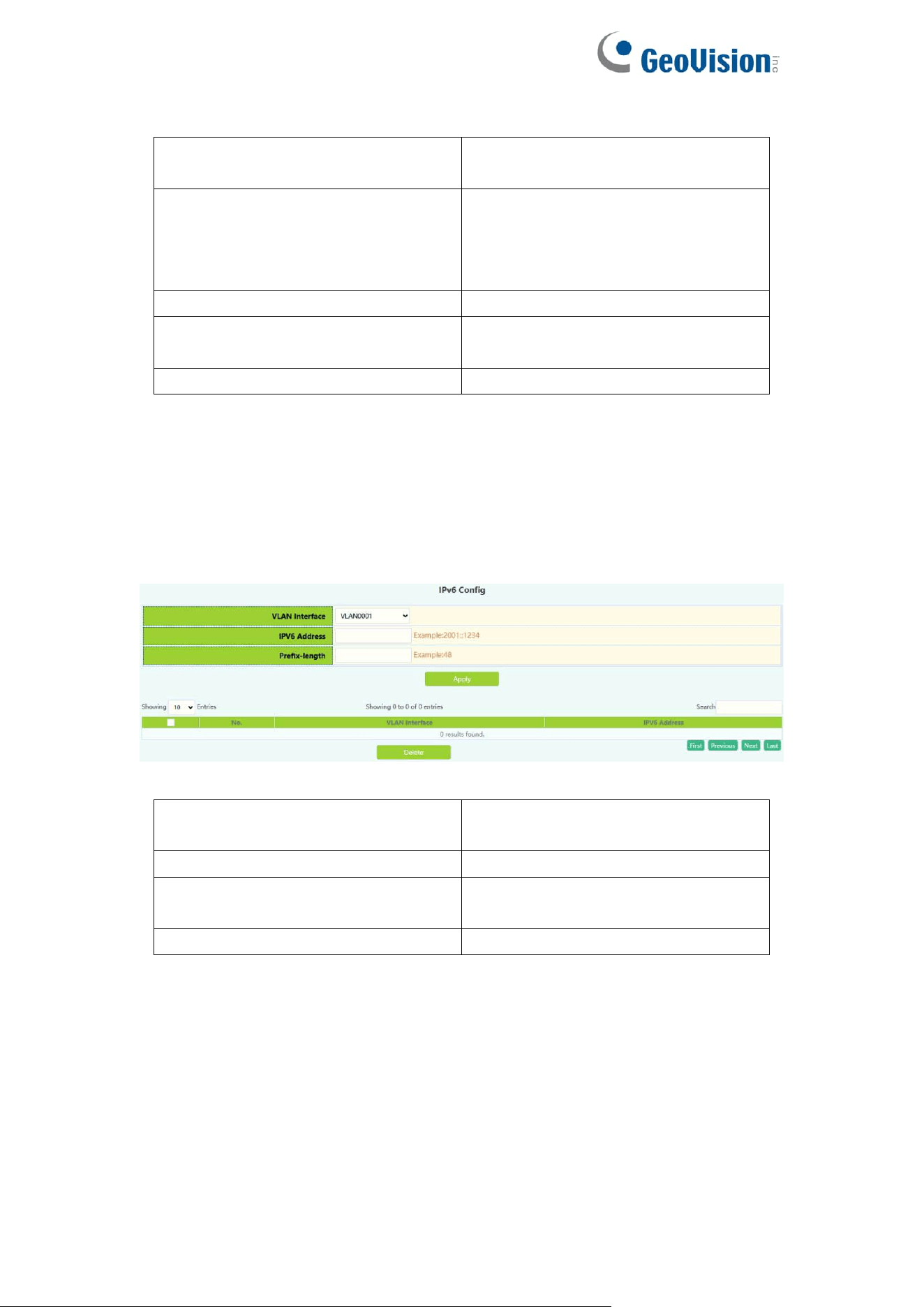
1.3.2.IPv6 Config
The page can be used to configure IPv6 address and subnet mask for the
VLAN interface.
To display the “IPv6 Config” page,click System Config ->IP Config->IPv6
Config,click "Apply" to configure.
VLAN Interface
VLAN ID of layer 3 interface
created
IPv6 Address
IPv6 Address, Example:2001::1234
Prefix-length
Prefix length is 3 to 127,
Example :48
Operation
Action: Apply/Delete
9
1.4.Web Config
1.4.1.Web Timeout
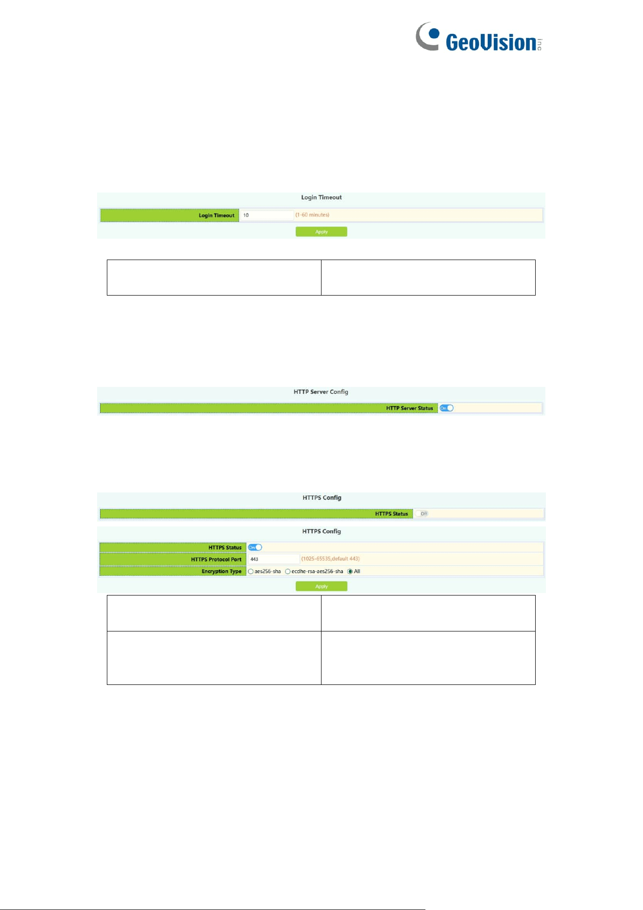
The page can be used to configure Web Login Timeout time.
Web Login Timeout
Web Login Timeout: 1-60
minutes,default 10 minutes
1.4.2.HTTP
HTTP Server Config module, the user can start or stop the HTTP service of the
switch by using this module again. Default is On.
1.4.3.HTTPS
HTTPS Server Config module, the user can start or stop the HTTPS service of
the switch by using this module again. Default is Off.
HTTPS Protocol Port
HTTPS Protocol Port:
1025-65535 ,default 443
Encryption Type
Type:
aes256-sha
ecdhe-rsa-aes256-sha
10
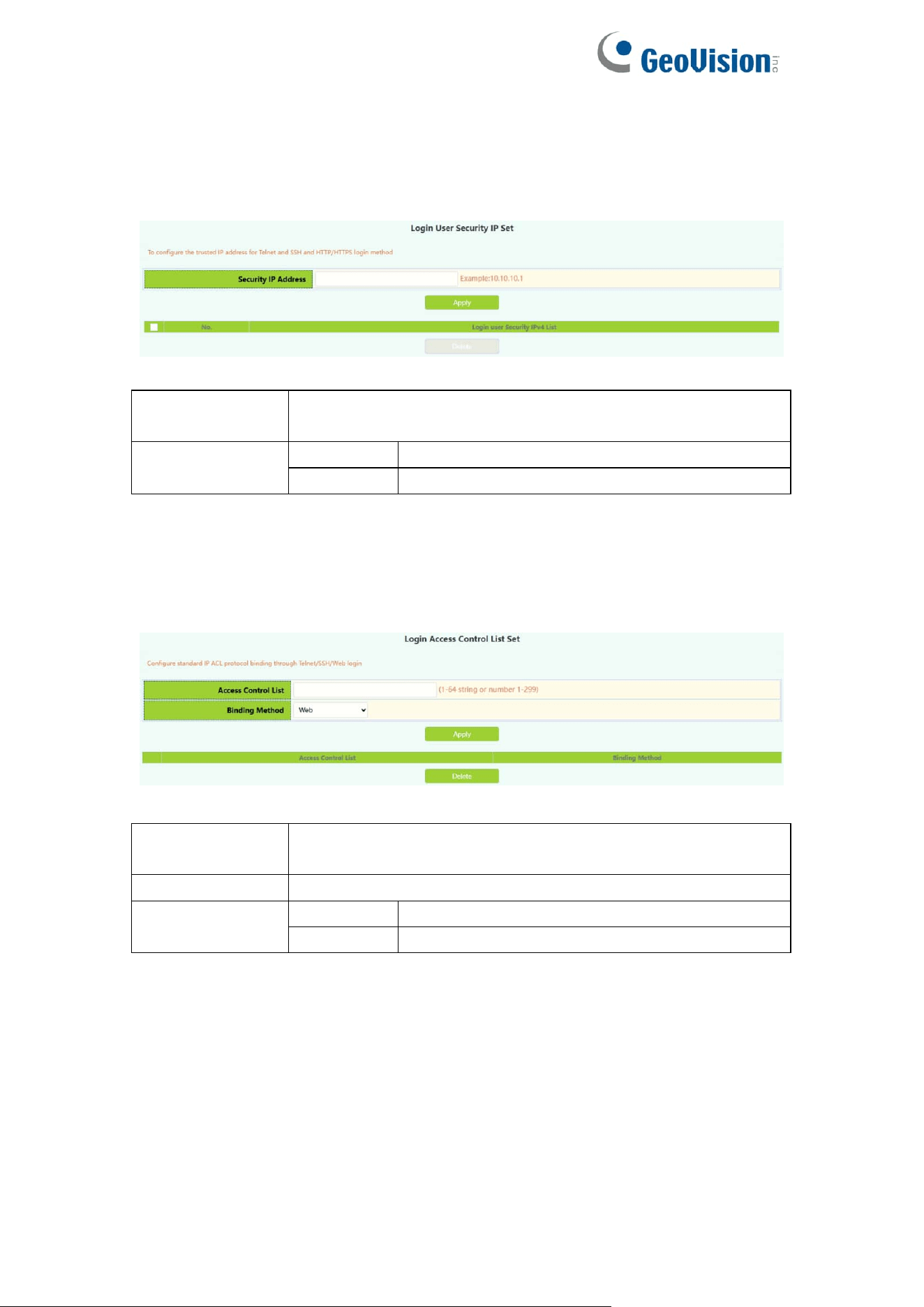
1.4.4.Security IP
Login user security IP configuration module, where users can configure the
security IPv4 address for login switch. Login methods include
Telnet/HTTP/HTTPS.
Security IP
address
Fill in the specified security IPv4 address
Operation
Apply
Add address or list number
Delete
Delete address or list number
1.4.5.ACL
Login user login access control list module, where users can configure the
IPV4 access control list. Login methods include Telnet/SSH/Web.
IPv4 access
control list
Standard access control list number, scope 1-64
characters or number 1-99
Binding Method
Binding Method include web/ssh/telnet/all
Operation
Apply
Add address or list number
Delete
Delete address or list number
11
1.5.User Management
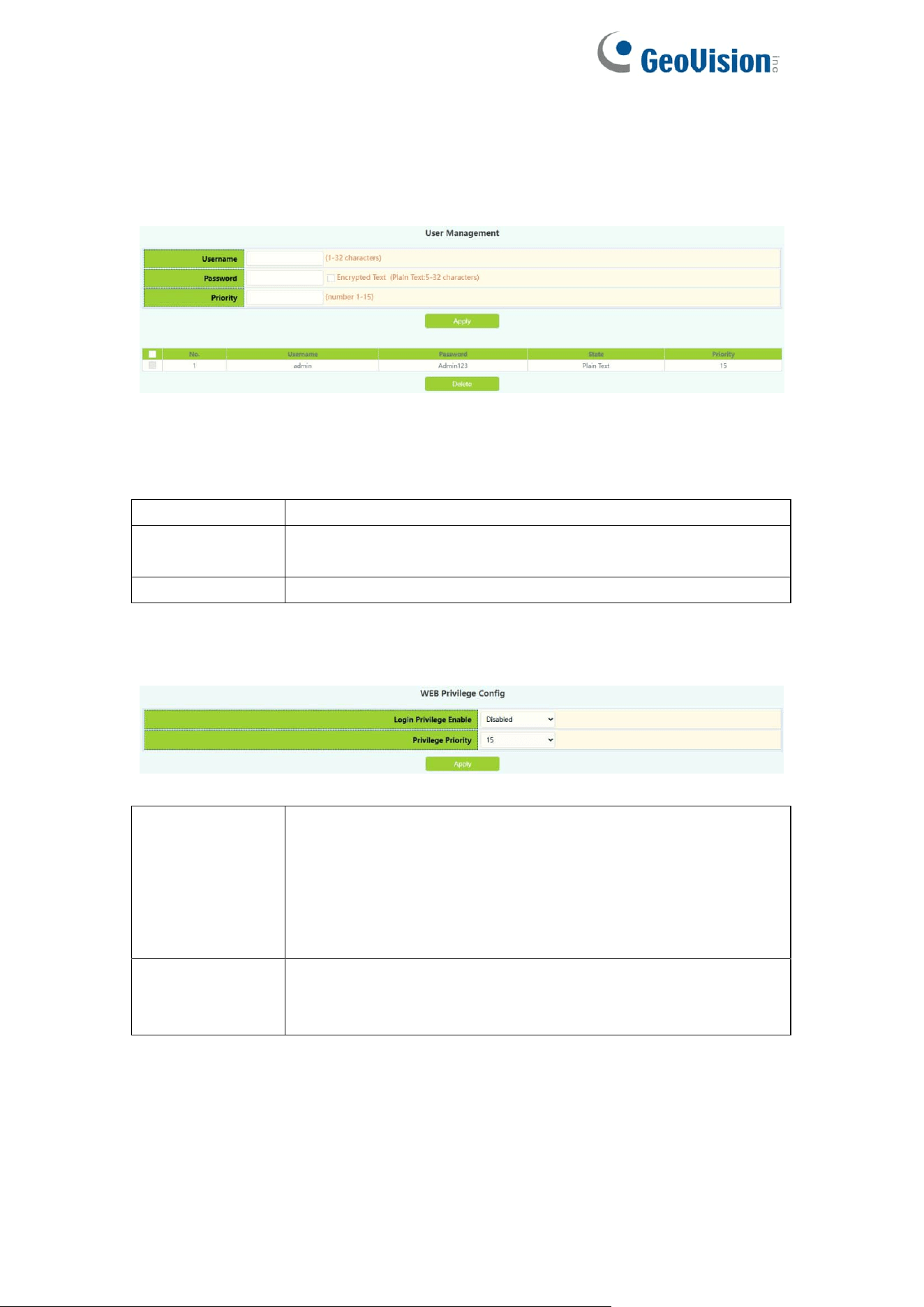
1.5.1.User Management
User Management module, users in this module can add or delete user
operations.
Username
User name to operate ,1-32 characters
Password
User password, choose the password encryption, otherwise
no encryption of 1-32 characters
Priority
Used to specify permission level.
WEB Privilege Config module, users can configure permissions for user
accounts to login in the web.
Login Privilege
Enable
Change the way users log in to web pages with
permissions, When the user priority is lower than the
privilege priority, it changes from being unable to log in to
being able to log in to the web page but not configure
information, and can only view the configuration. Default is
disable.
Privilege
Priority
Used to specify permission level, default level 15, only the
user with the level that is equal to or higher than it can login
in the switch by web.
12
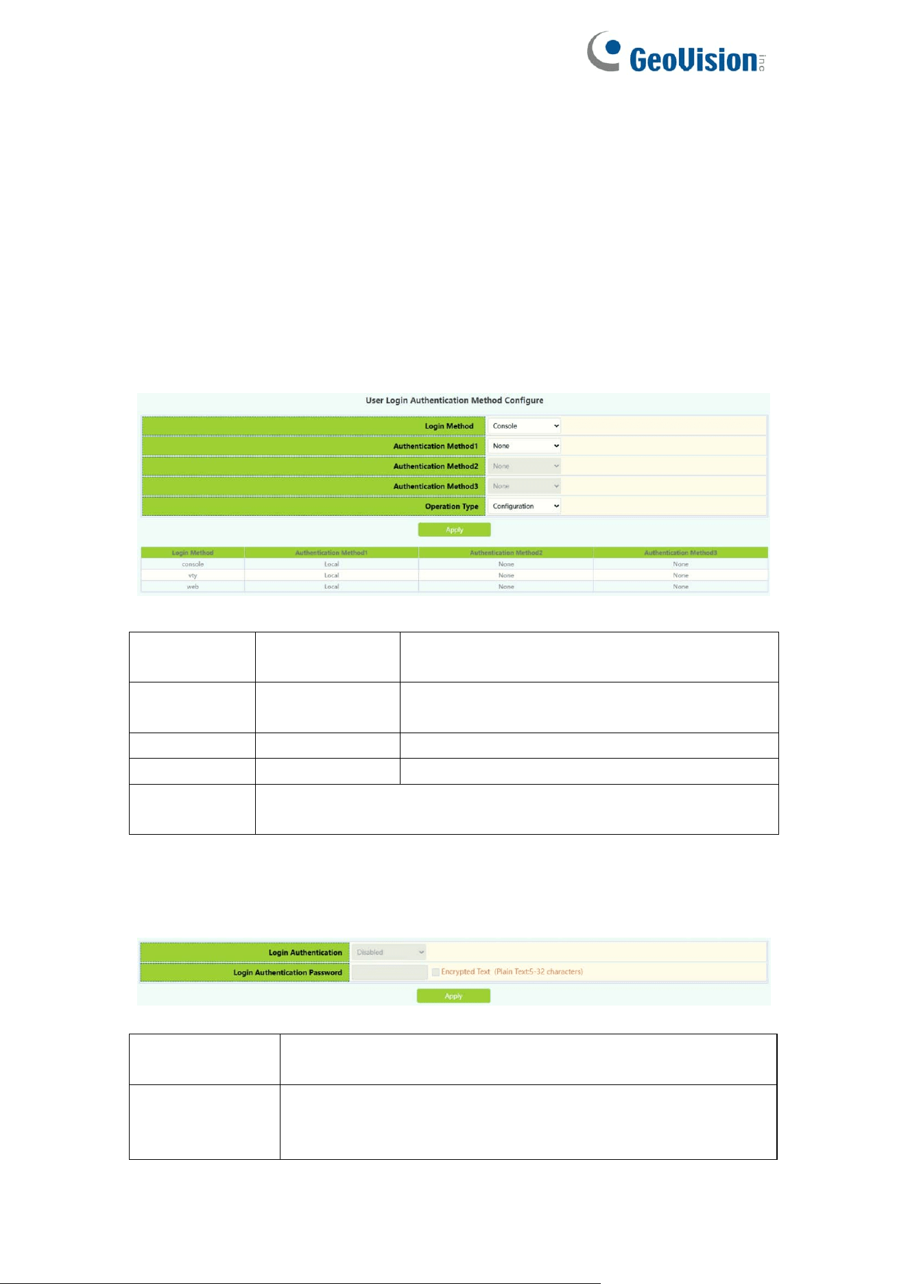
1.5.2.Authentication Method
User Login Authentication Method Configure module, the user can configure
console.vty.web authentication method used in login, authentication method
can be any one or combination of Local.RADIUS and TACACS preferences
from left to right when the login method is combined configuration. If the user
has passed the authentication method, the authentication method of the lower
preference is ignored. As long as you pass an authentication method, the user
can log in.AAA functions and RADIUS servers should be configured before
using RADIUS authentication.If local authentication is configured without
configuring a local user, the user will be able to log on to the switch through the
console method.
Login
method
Authentication
method
Console, vty and web.
console
local
Authentication using the local user account
database
vty
radius
Authentication using remote Radius server
web
tacacs
Authentication using remote Tacas server
Default
Default console no authentication , vty and web local
authentication
Only when the console authentication mode is 'none', can the login
authentication mode be configured.
Login
Authentication
Default is Disable.
Login
Authentication
Password
Login Authentication password, choose the password
encryption, otherwise no encryption of 1-32 characters
13
1.6.Firmware Upgrade
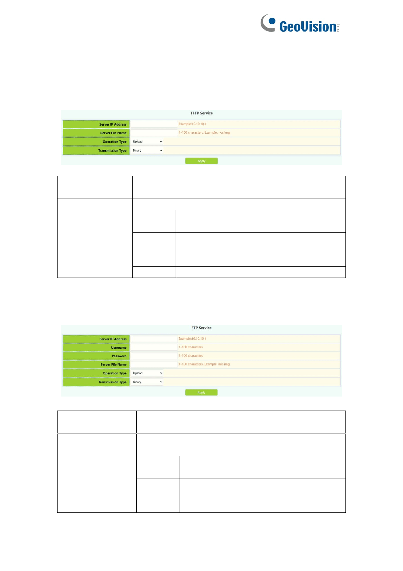
1.6.1.TFTP Service
TFTP client service module, the user can upload or download files by TFTP
way, and can upgrade the firmware of the switch by this method.
Server IP
address
TFTP address IP peer server, point decimal
Server File name
Source name to upload or download ,1-100 characters
Operation type
Upload
Upload upgrade files from the switch to the
TFTP server
Download
Download upgrade files from TFTP server to
switch
Transmission
type
binary
Transfer files in binary format (default)
ascii
Transfer files in ascii format
1.6.2.FTP Service
FTP client service module, the user can upload or download files by FTP way,
and can upgrade the firmware of the switch by this method.
Server IP Address
FTP address IP peer server, point decimal
Username
FTP server-to-server username ,1-100 characters
Password
FTP server-side user password 1-100 characters
Server File Name
Source name to upload or download ,1-100 characters
Operation Type
Upload
Upload upgrade files from the switch to the
TFTP server
Download
Download upgrade files from TFTP server to
switch
Transmission
binary
Transfer files in binary format (default)
14
Type
ascii
Transfer files in ascii format
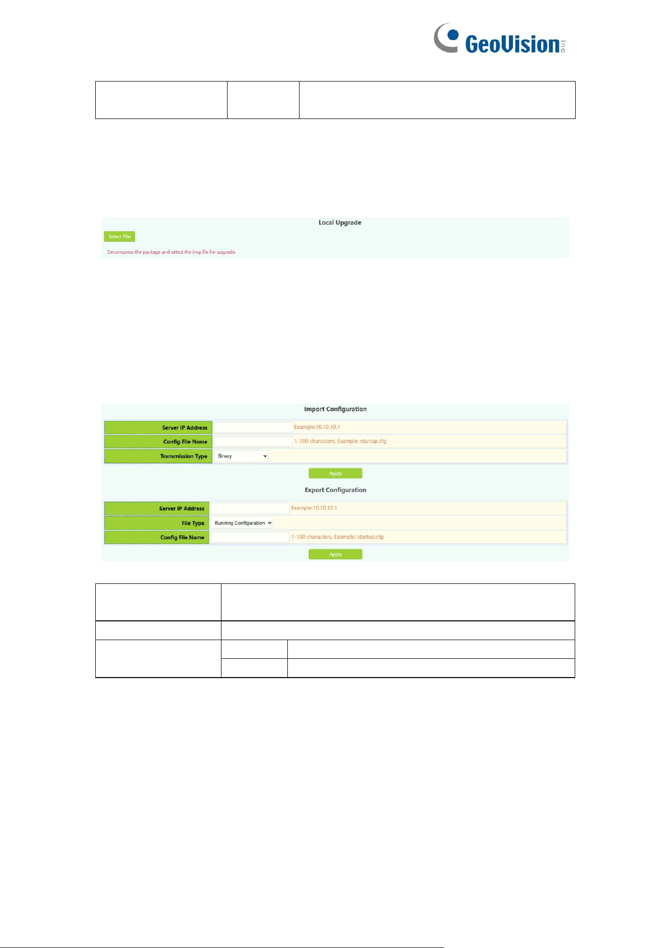
1.6.3.HTTP Upgrade
HTTP Upgrade module, the user can select file by HTTP way, and can
upgrade the firmware of the switch by this method.
1.7.Management Config
1.7.1.TFTP
TFTP module, the user can import or export switch configuration by tftp.
Server IP
Address
TFTP address IP peer server, point decimal
Server File Name
Source name to upload or download ,1-100 characters
Transmission
Type
binary
Transfer files in binary format (default)
ascii
Transfer files in ascii format
15
1.7.2.HTTP
HTTP module, the user can Download or Upload switch Running
Configuration or Startup Configuration by http.
Operation Type
Download
To download files
Upload
To upload files
File Type
Running Configuration
Switch running configuration
Startup Configuration
Switch startup configuration
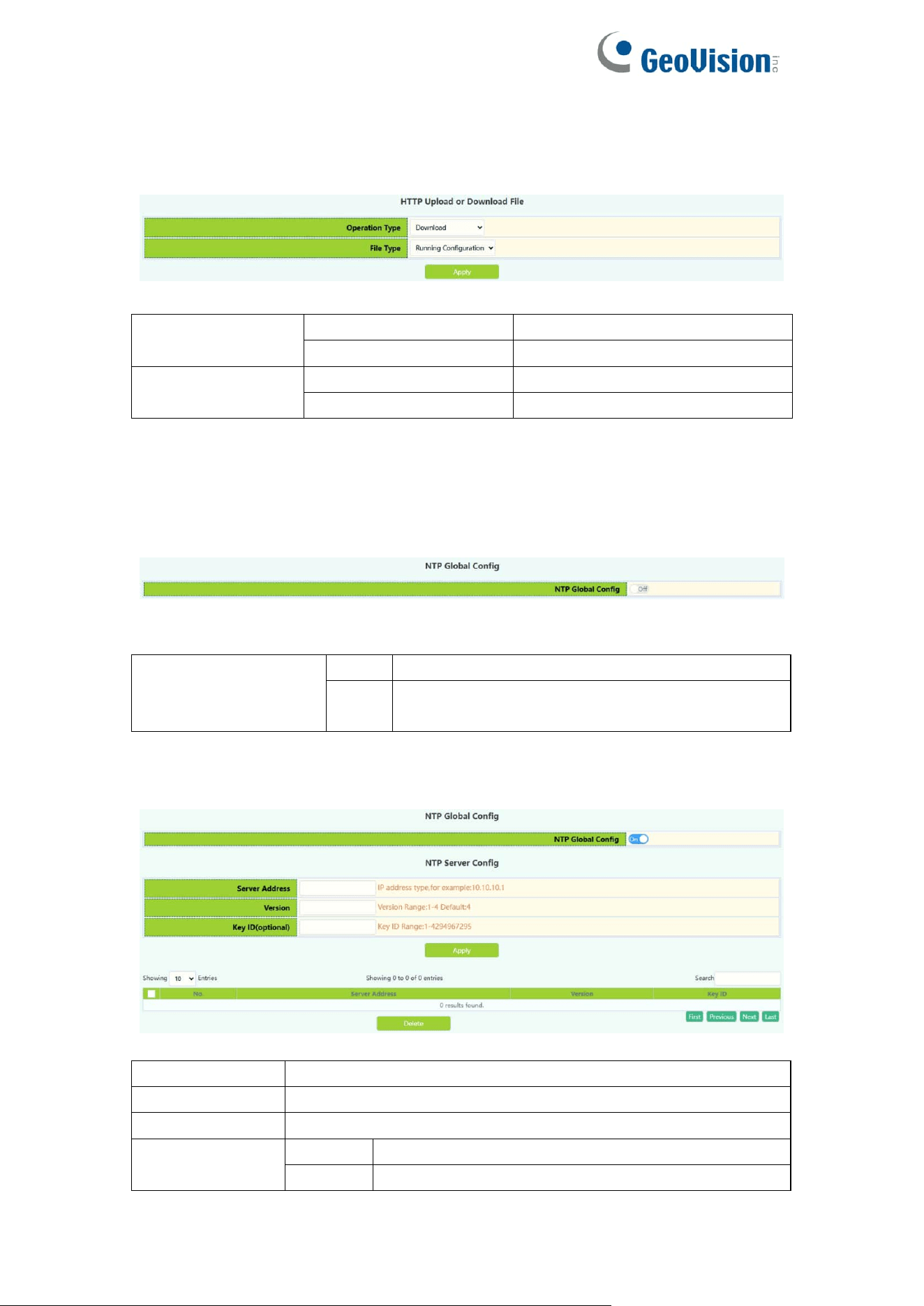
1.8.NTP
1.8.1.NTP Config
NTP Config module, user can NTP service global switch operation.
NTP Global config
Operation
Off
Close operation(default)
On
Start
NTP the server configuration module, the user can configure the specified time
server of the switch time source in this module.
Server address
The specified time server address decimal point
Version
Version number, range 1-4, default 4
Key ID
Secret key value, range 1-4294967295
Operation
Apply
Add operations
Delete
Delete operations
16
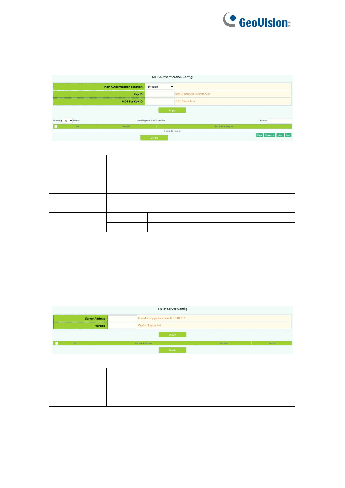
1.8.2.NTP Authentication Config
NTP verification configuration module, the user can configure the switch NTP
authentication related items.
NTP
authenticate
switch
Disable
Close NTP validation (default)
Enable
Enable NTP validation
Key ID
Secret key value, range 1-4294967295
MD5 For Key ID
The MD5 value of the secret key, which ranges from 1-16 of
ascii code
Operation
Apply
Add operations
Delete
Delete operations
1.9.SNTP
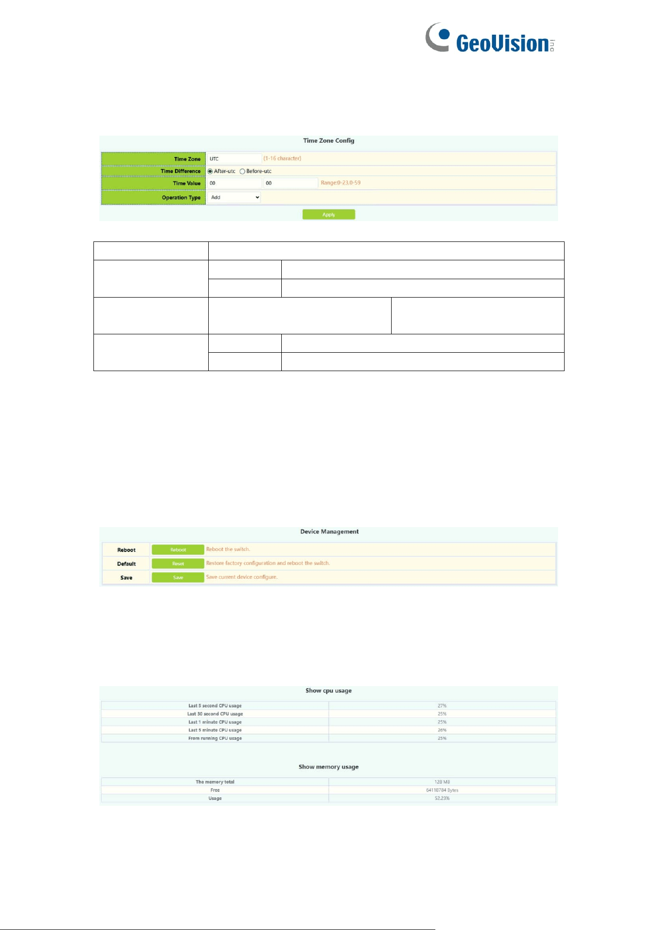
1.9.1.Server Config
SNTP the server settings module, the user can add or delete the specified time
server as the clock source.
Server address
The specified time server address decimal point
Version
Version number, range 1-4, default 4
Operation
Apply
Add operations
Delete
Delete operations
17
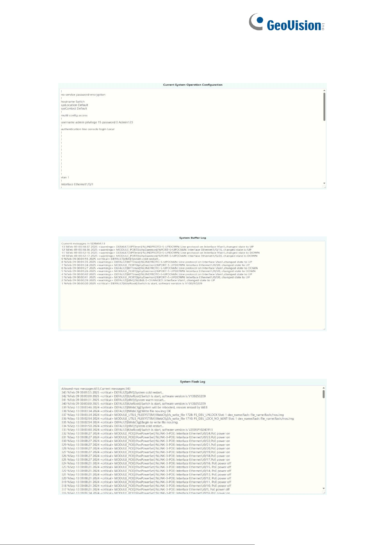
1.9.2.Time Zone Config
SNTP the time zone and UTC time difference setting module where the client
is located, the user can set the switch's current time zone and name it.
Time zone
Time zone name ,1-16 characters
Time difference
After-utc
Increased time zone behavior
Before-utc
Reduced time zone behavior
Time value
Time zone specific change
hours 0-23
Time zone specific change
minute value 0-59
Operation
Add
Add operations
Default
Restore time zone default configuration
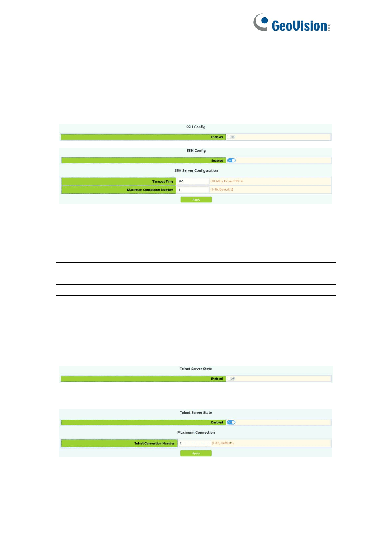
1.10.Device Management
1.10.1.Device Reboot/Reset
Device Reboot/Reset module, the user can restart the switch by Reboot
button. can also leave the factory initial settings restart by Reset button, but
also can save the current set configuration by Save button.
1.10.2.System Utilization
This module is used to display resource usage cpu current system but also
display the current system memory resource usage.
18
1.10.3.View System Config
This module is used to display configuration information in the current system
run.
1.10.4.View Logging Buffer
This module is used to display system logging information in the current
system run.
1.10.5.View Logging Flash
This module is used to display system flash log information in the current
system run.
19
2.Monitor Management
2.1.SSH Config
SSH Config module, the user can configure the SSH status and SSH timeout.
Enabled
Operation
Off: Close operation(default)
On: Start
Timeout
Time
Timeout of exit SSH login status ,10-600 seconds(default 180 s)
Maximum
Connection
Maximum number of connections logged in by SSH, range
1-16(default 5)
Operation
Apply
Add operations
2.2.Telnet Config
Telnet server status module, where users can enabled on or off login switches
by Telnet.
Telnet connect the maximum number module, the user can configure the
maximum number of connections to the switch by Telnet.
Telnet access
connection
number
Maximum number of connections logged in by Telnet, range
1-16(default 5)
Operation
Apply
Add operations
20
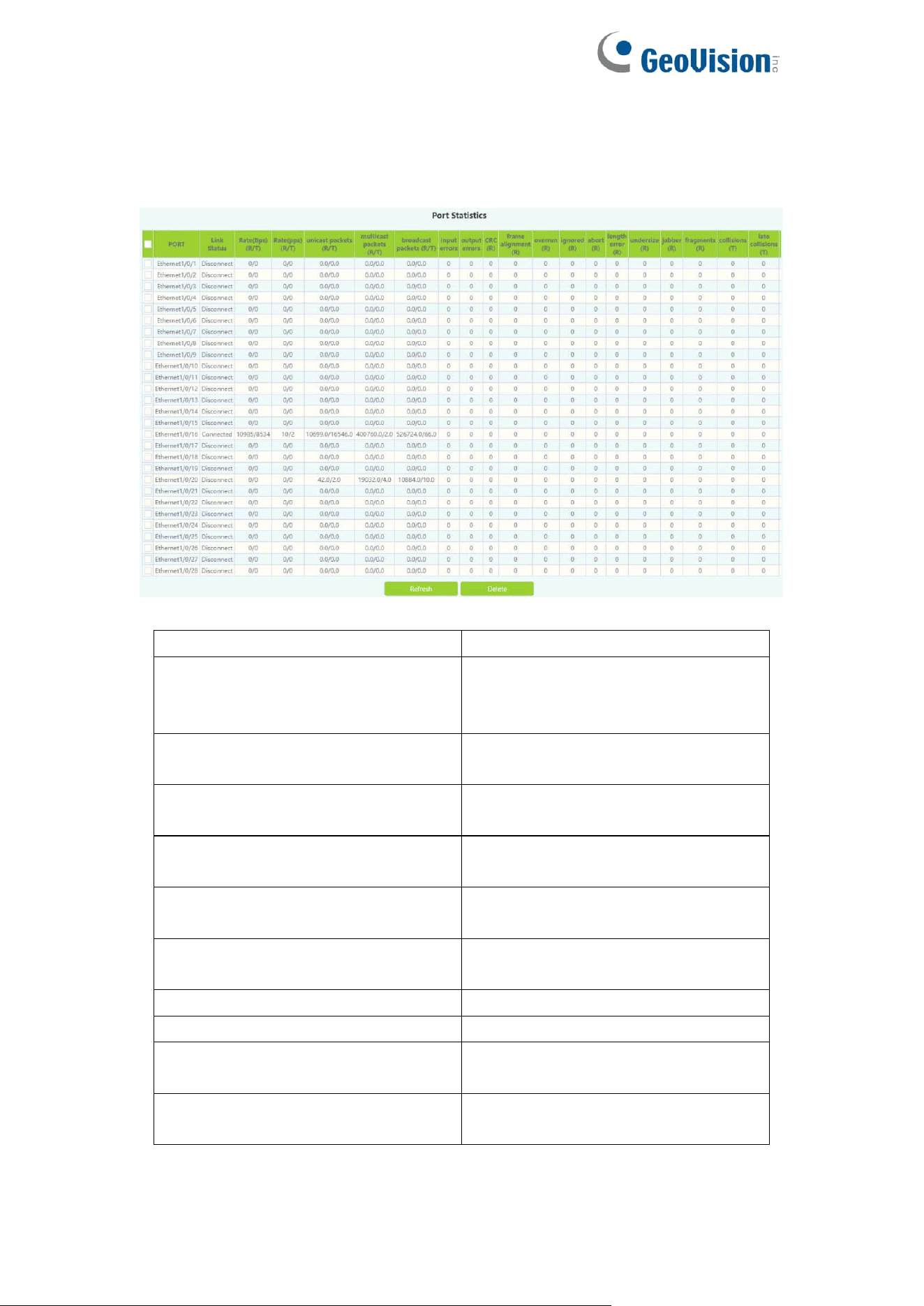
2.3.Port Statistics
This page displays port statistics information.
Port
physical ports
Link Status
Link Status:
Connected;
Disconnect
Rate(bps)
(R/T)
Rate(bps):
Received/Transmit;
Rate(pps)
(R/T)
Rate(pps):
Received/Transmit;
Unicast packets(R/T)
Unicast packets:
Received/Transmit;
multicast packets(R/T)
multicast packets:
Received/Transmit;
brocast packets(R/T)
brocast packets:
Received/Transmit;
Input errors
Input erros
output errors
Output erros
CRC(R)
CRC(Cyclic Redundancy Check)
Received;
frame alignment (R)
Frame Alignment
Received;
21
overrun (R)
Overrun
Received;
ignored (R)
Ignored
Received;
abort (R)
Abort
Received;
length error (R)
Length error
Received;
undersize (R)
Undersize
Received;
jabber (R)
Jabber
Received;
fragments (R)
Fragments
Received;
collisions (T)
Collisions
Transmit;
late collisions (T)
Late Collisions
Transmit;
pause frame (R/T)
Pause Frame
Received/Transmit;
Refresh
Refresh Port Statistics
Delete
Select the port and click delete to
clear Port Statistics
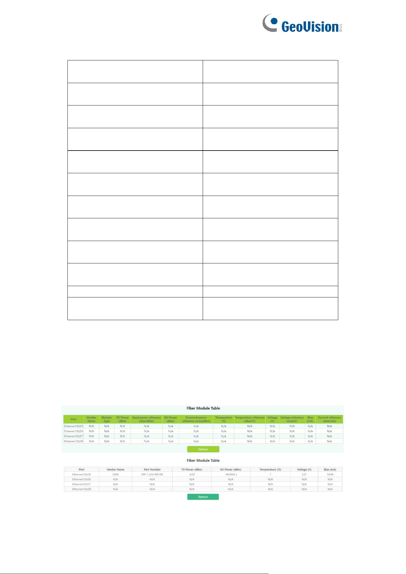
2.4.DDMI Status
This page displays fiber module information.
22
Port
fiber ports
Temperature (℃)
Display the temperature of the fiber
module
Bias (mA)
Display the Bias of the fiber
module.
RX Power (dBm)
Display the RX Power of the fiber
module.
TX Power (dBm)
Display the TX Power of the fiber
module.
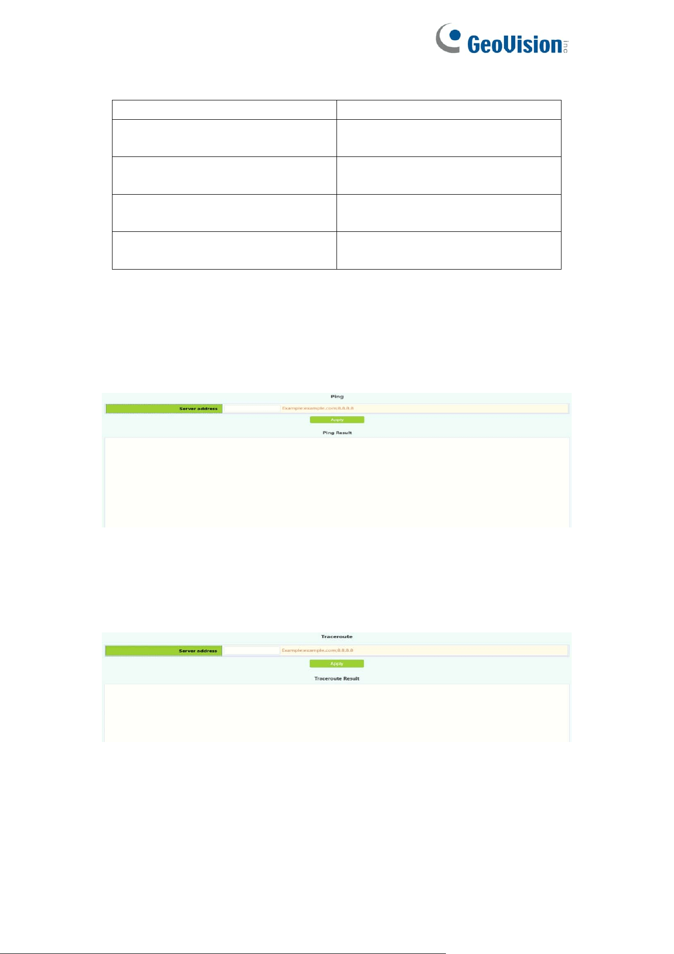
2.5.Ping
The user can run ping command.
2.6.Traceroute
The user can run route tracking command.
23
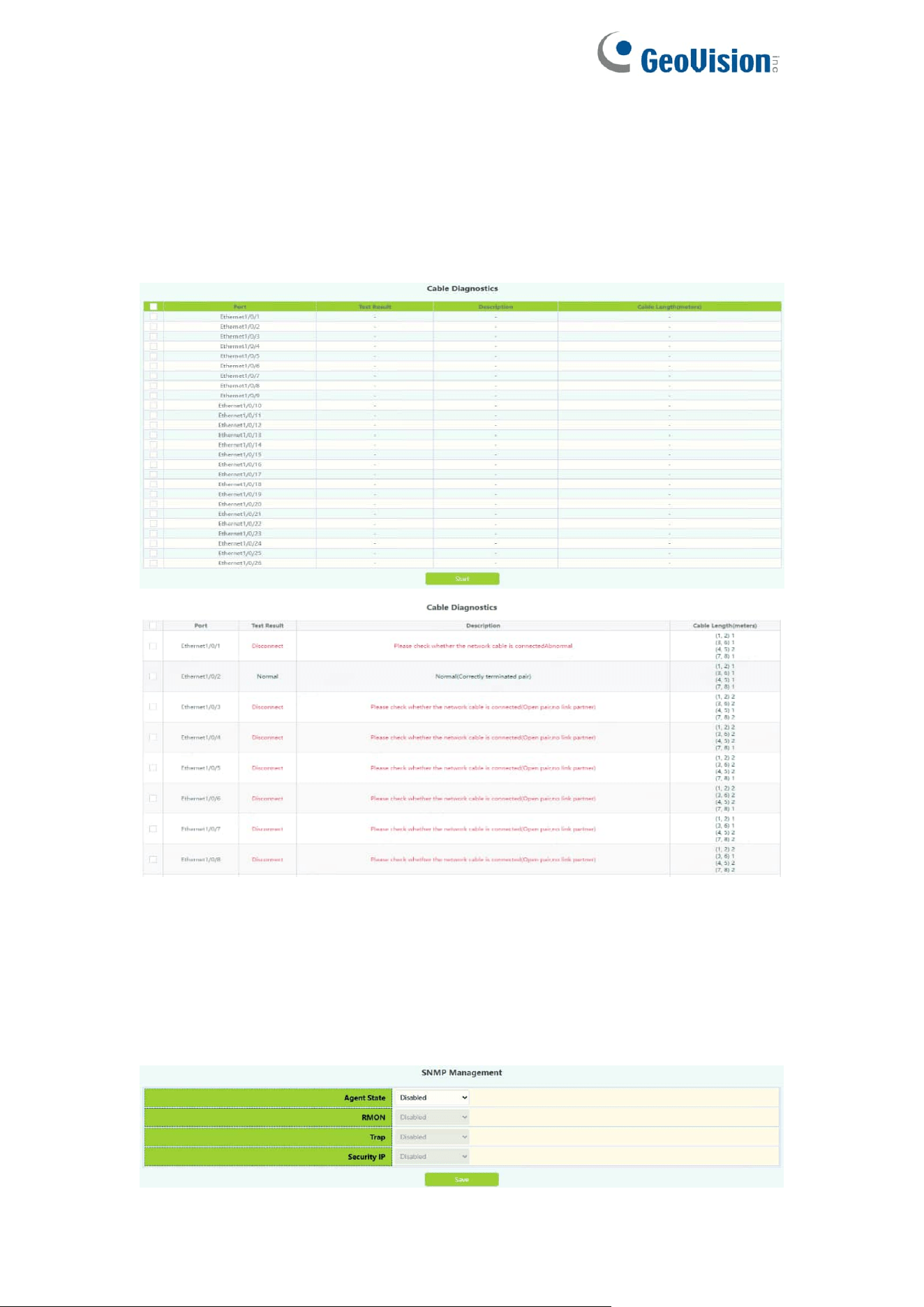
2.7.Cable Diagnostics
This chapter can be used to detect port link lines.
To display the “Cable Diagnostics” page,click Monitor Management
->Cable Diagnostics,click "Apply" to configure.
2.8.SNMP Config
2.8.1.Global Config
SNMP network management function switch module, users can enable or
disable SNMP functions. SNMP Agent State and Trap state default is disable.
Security IP state
24
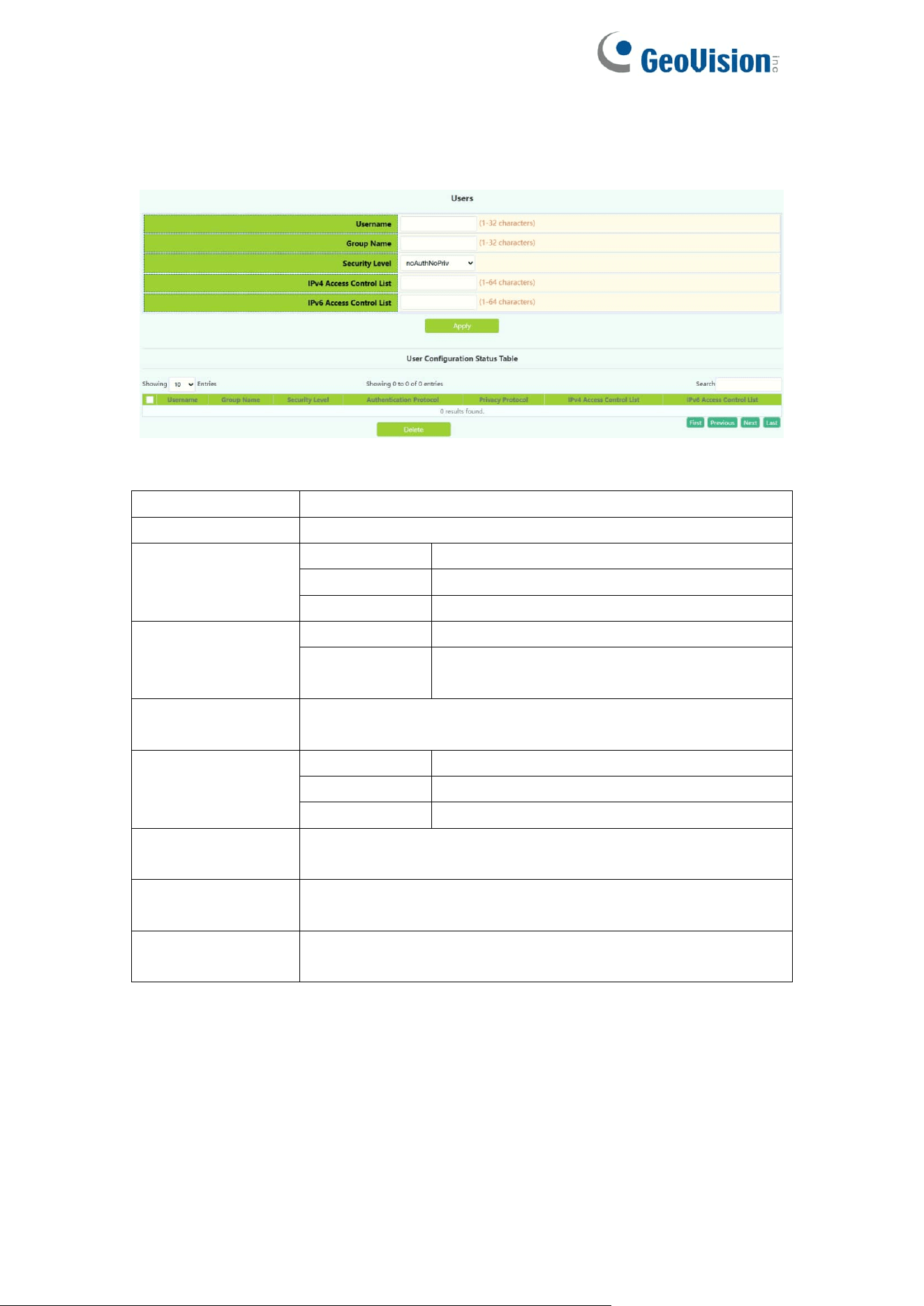
2.8.2.User Config
SNMP user management module, users can add or delete SNMP user
operations in this module.
Username
User name to operate ,1-32 characters
Group Name
User group to join ,1-32 characters
Security Level
noAuthNoPriv
Uncertified non-encrypted level
authNoPriv
Authentication but not encryption level
authpriv
Authentication and encryption level
Authentication
protocol:
MD5
HMAC MD5 algorithm for authentication
SHA
Authentication uses HMAC SHA
algorithms
Authentication
password:
Password for authentication
Privacy protocol:
DES
Encryption DES algorithm
AES
Encryption AES algorithm
3DES
Encryption with 3 DES algorithm
Privacy
password:
Password for encryption
IPv4 access
control list
Standard IPv4 access control list number, range 1-64
characters
IPv6 access
control list
Standard IPv6 access control list number, range 1-64
characters
25
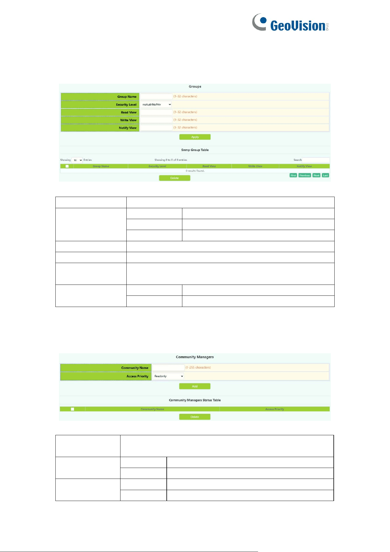
2.8.3.Group Config
SNMP group management module in which users can add or delete SNMP
group operations.
Group Name
User group name to operate ,1-32 characters
Security level
noAuthNoPriv
Uncertified non-encrypted level
authNoPriv
Authentication but not encryption level
authpriv
Authentication and encryption level
Read SNMP view
Name of readable view, including 1-32 characters
Write SNMP view
Name of writable view, including 1-32 characters
Notify SNMP
view
Notice the name of the view, including 1-32 characters
Operation
Apply
Add SNMP groups
Delete
Delete SNMP groups
2.8.4.Community Config
The community management module where users can configure SNMP
community management.
Community
Name
Community string name ,1-255 characters
Access Priority
Read only
Read-only permission level
Read-write
Read and write permission level
Operation
Add
Do Community string add operations
Delete
Do Community string delete operations
26
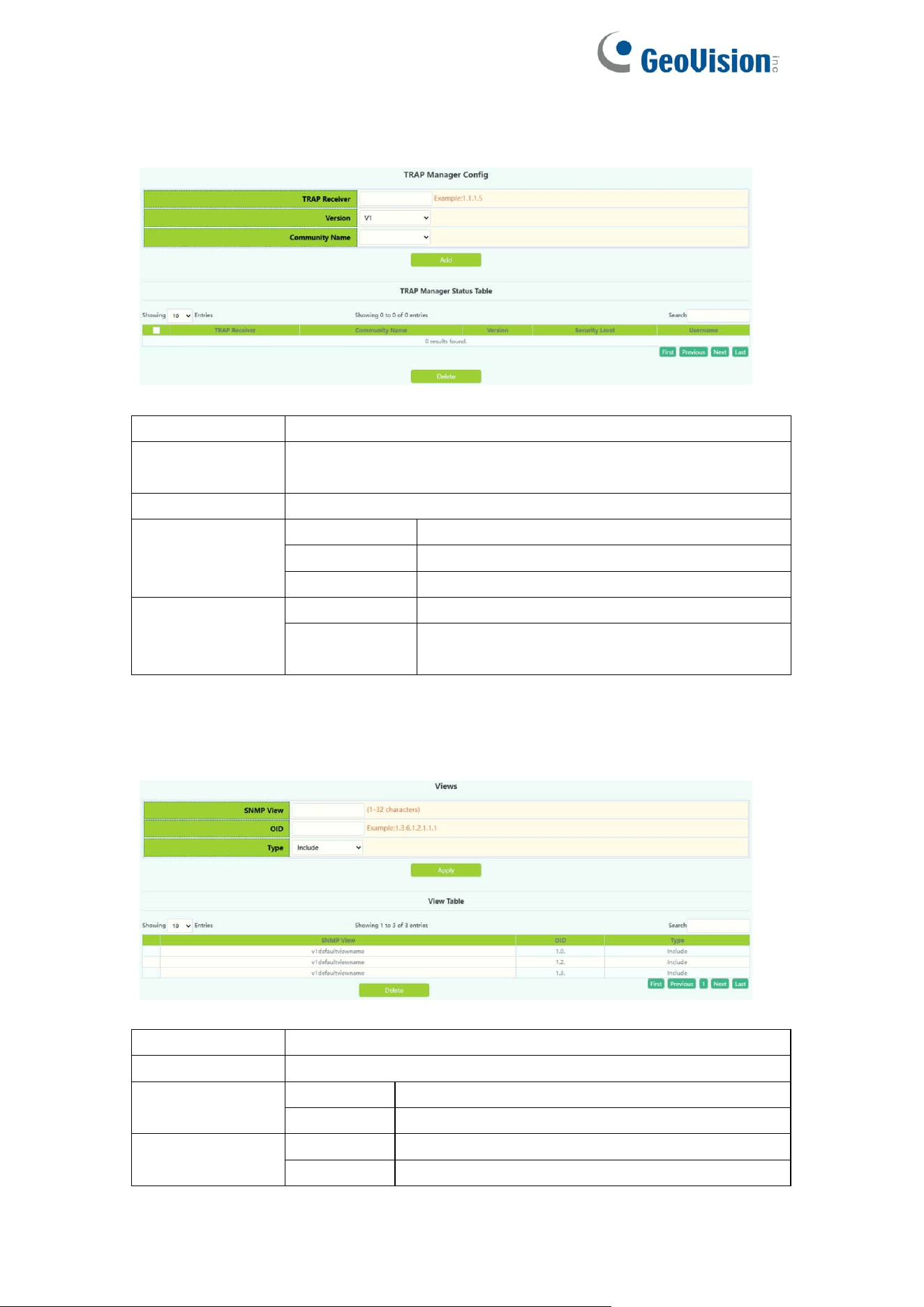
2.8.5.Trap Config
The trap config where users can configure trap management settings.
Trap Receiver
Recipient IPv4/IPv6 address of Trap information
Community
Name
Community string name, V1/V2 version :1-255 characters,
V3 version :1-24 characters
Version
Three versions:V1/V2C/V3
Security level
(V3 version
support only)
noAuthNoPriv
Uncertified non-encrypted level
authNoPriv
Authentication but not encryption level
authpriv
Authentication and encryption level
Operation
Add
For Trap information receiver add operation
Delete
For Trap information receiver remove
operation
2.8.6.View Config
SNMP view management module in which users can add or delete SNMP view
operations.
SNMP view
User view name to operate, 1-32 characters
OID
OID number to operate, decimal
Type:
Include
Include this OID
Exclude
Exclude this OID
Operation
Apply
Add view
Delete
Delete View
27
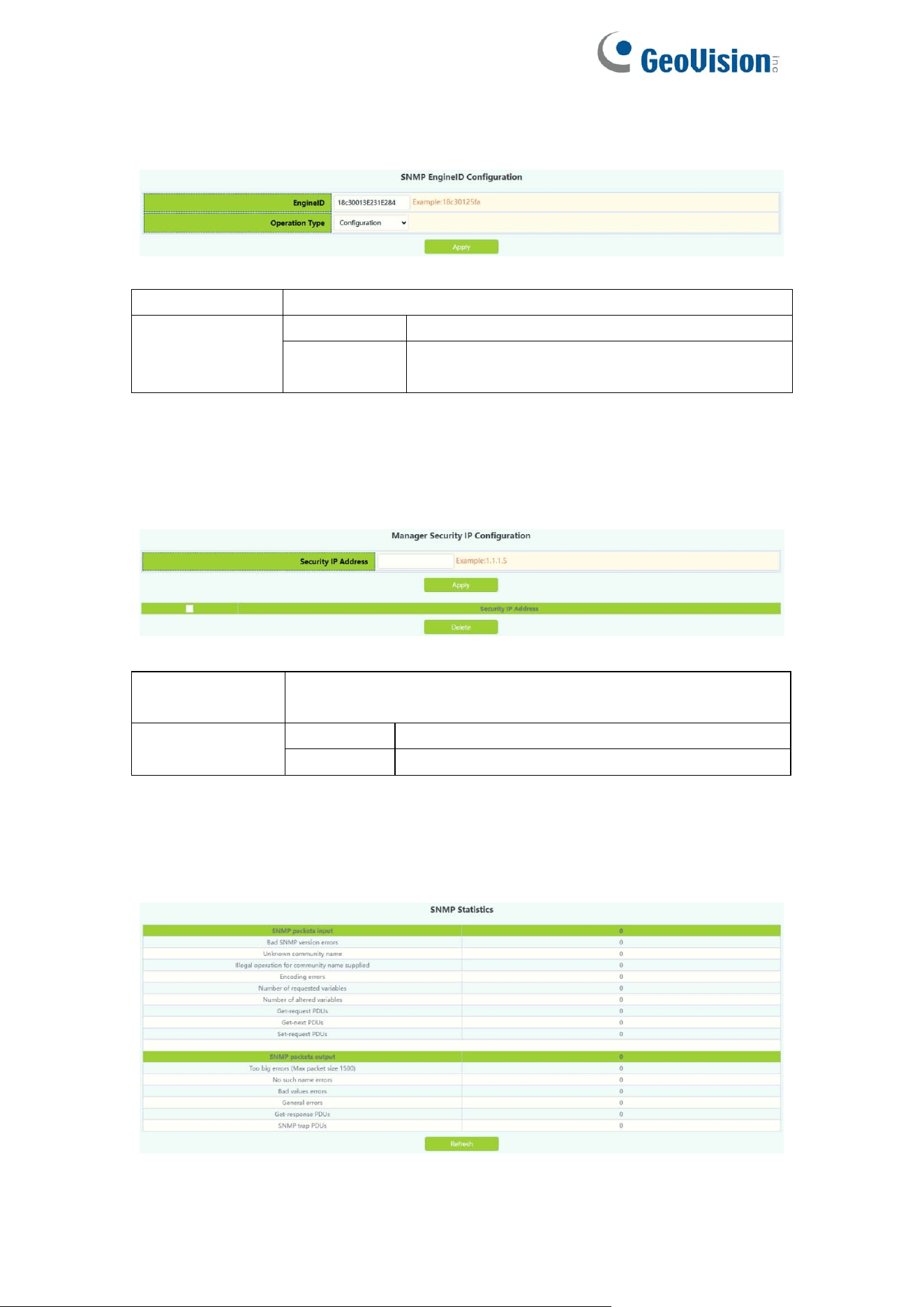
SNMP Engineid configuration module, the user can configure SNMP Engineid
operation in this module.
Engineid
Engine id,Hex ,1-32 characters
Operation
configuration
Configuration operations
Default
Restore default (default is company ID plus
local MAC address)
2.8.7.Security IP Config
The administrator IP the address setting module, where the user can add or
delete the SNMP manager's safe IP address.
Security IP
address
SNMP Management Security IPv4/IPv6 Address
Operation
Apply
Add a Security IP
Delete
Delete a Security IP
2.8.8.SNMP Statistics
SNMP statistical information module, users in this module can view the SNMP
function feedback information.
28
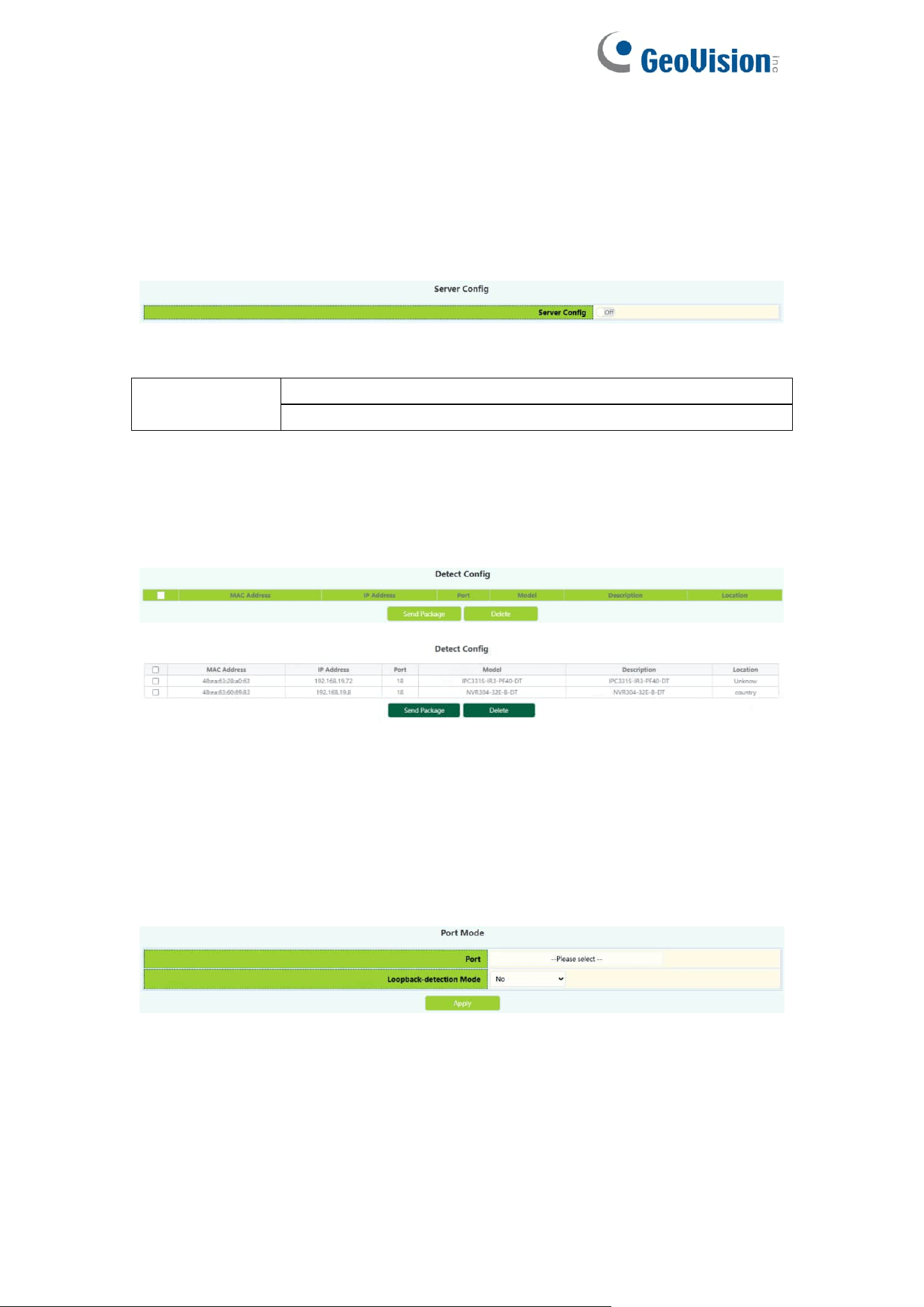
2.9.Onvif Config
2.9.1.Server Config
Onvif server global switch configuration module, user can Onvif server global
switch operation.
Server config
Operation
Off: Close operation(default)
On: Start
2.9.2.Detect Config
Onvif detect config module, Click the Send button to send an Onvif detection
packet to discover the device.
2.10.Loopback Detection
2.10.1.Port Mode
The configuration of the page is used to set the loop detection control method.
To display the “Port Mode” page,click Monitor Management ->Loopback
Detection->Port Mode,click "Apply" to configure.
29
Port
Ethernet port name
Loopback-detection mode
Operation in case of loop:
No: no control mode
Shutdown:Disable port
block :Block port
Operation
Operation of loop detection
function:
Apply:Configure control mode
Port
Ethernet port name
Loopback-detection mode
Shutdown:Disable port
block :Block port
No:Disable port loop detection
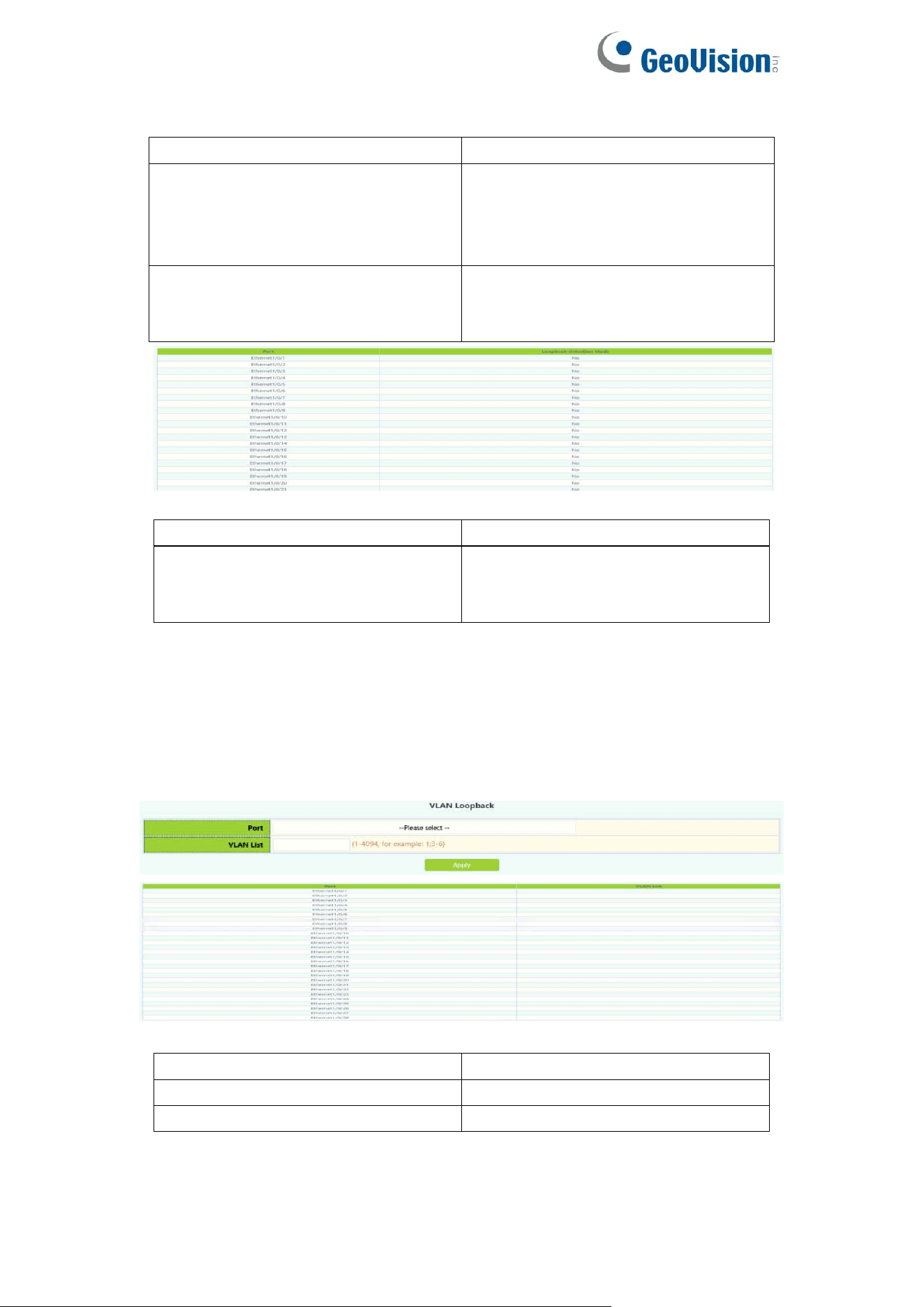
2.10.2.VLAN Loopback
This page can be used to configure VLAN loop detection function enabled or
disabled.
To display the “VLAN Loopback” page , click Monitor Management
->Loopback Detection->VLAN Loopback,click "Apply" to configure.
Port
Ethernet port name
VLAN ID
VLAN ID, range 1-4094
Operation
Apply:Set VLAN loop detection
30
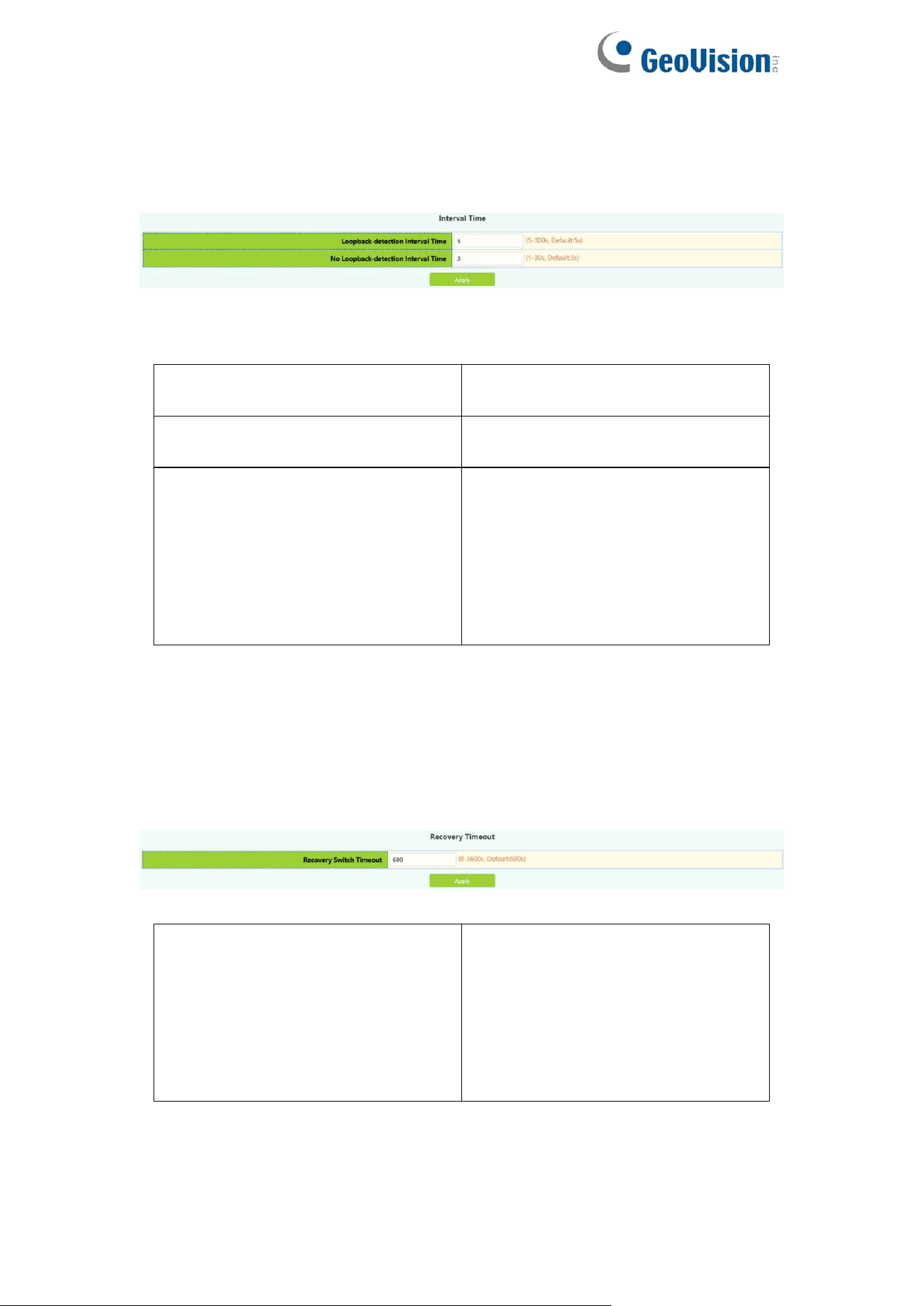
2.10.3.Interval Time
This page can be used to configure the loop detection interval.
To display the “Interval Time” page,click Monitor Management ->Loopback
Detection-> Interval Time,click "Apply" to configure.
Loopback-detection interval time
Interval time between loops, size
5-300 seconds, default is 5.
No Loopback-detection interval
time
No loop interval, size 1-30
seconds, default is 3.
Operation
Configuration:Set the test time by
yourself.
Default : Restore the default
configuration, there is a loop
detection interval of 35 seconds,
there is no loop detection interval of
15 seconds.
2.10.4.Recovery Timeout
This page is used to configure loop detection to automatically return to an
uncontrolled state.
To display the “Recovery Timeout” page , click Monitor Management
->Loopback Detection-> Recovery Timeout,click "Apply" to configure.
Recovery switch timeout
When a port is disabled or blocked
due to a loop, it automatically
recovers to an uncontrolled time,
the size range is 0-3600 seconds.
When it is configured as 0, the auto
recovery function is disabled.
Default is 600
31
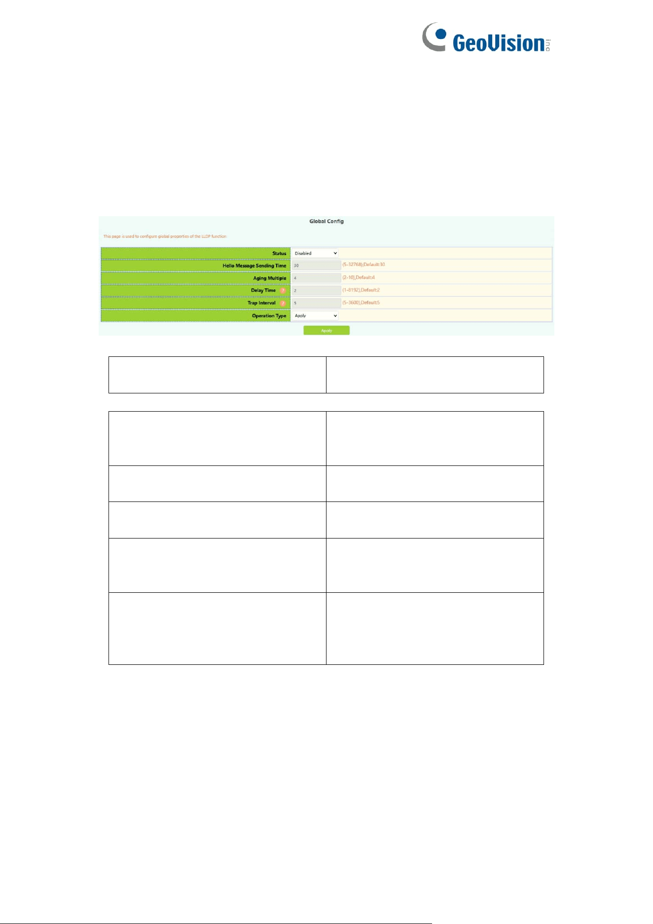
2.11.LLDP Config
2.11.1.Global Config
This page can be configured to enable or disable LLDP functionality,
configure the interval between sending updates, configure the value of the
message aging time multiplier, configure the sending delay time of the update
message, configure the interval between sending Trap messages.
Status(lldp enable)
Enable:Global On LLDP Function
Disable:Global Off LLDP Function
Hello Message Sending Time
Update message sending interval
between 5-32768 seconds. the
default configuration is 30 seconds.
Aging Multiple
Numerical magnitude between
2-10, the default configuration is 4
Delay Time
Value between 1-8192 seconds,
the default configuration is 2
Trap Interval
Value between 5 and 3600
seconds, the default configuration
is 5
Operation Type
Apply:
User self-configuration
Default:
Restore default configuration
32
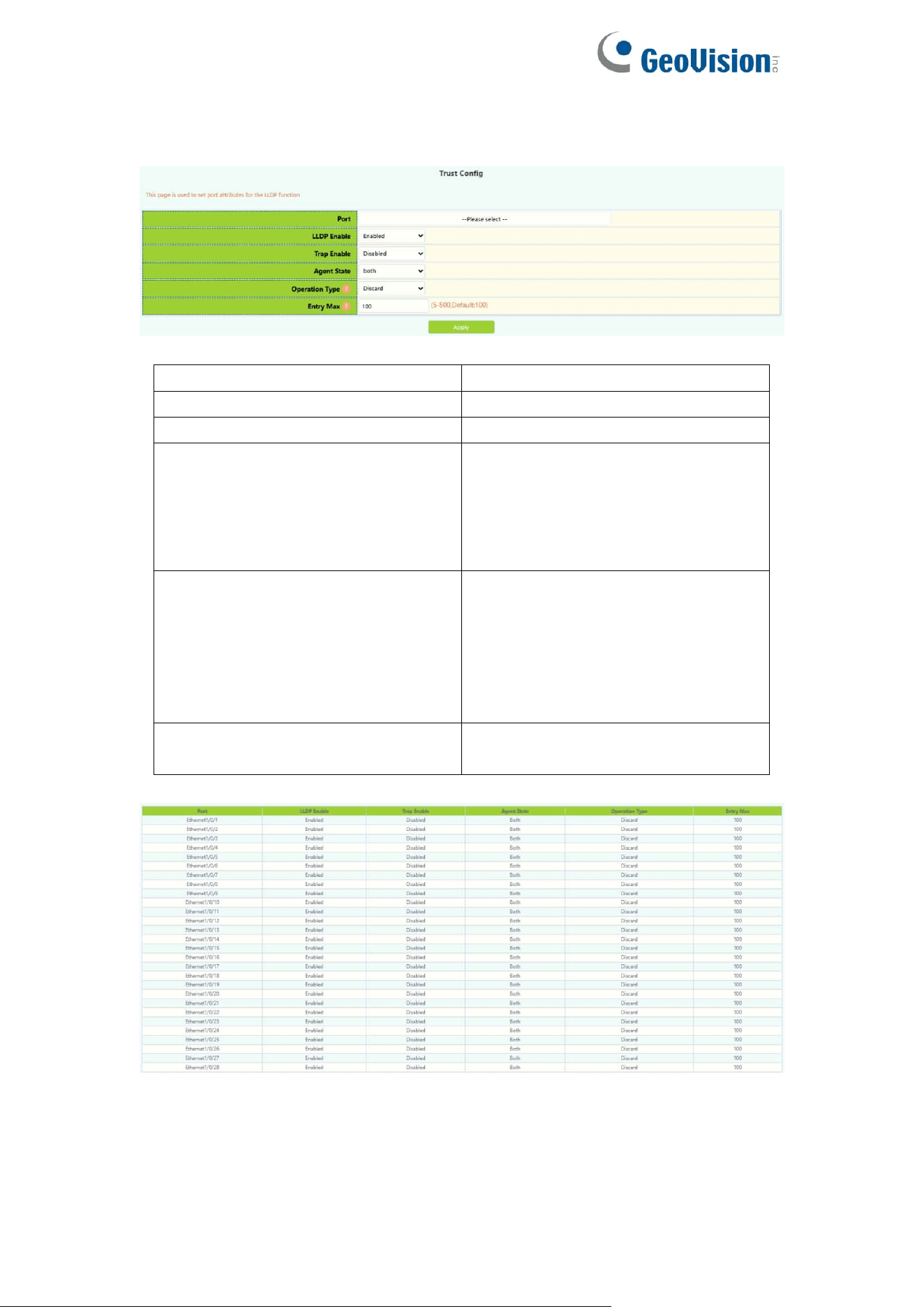
2.11.2.Port Config
This page can be configured to enable or disable LLDP Port functionality.
Port
Ethernet port name
LLDP port Enable type
Enable or disable LLDP functions
LLDP port Trap enable type
Enable or disable Trap functions
LLDP mode
Agent State:
Send;
Receive;
Both;
Disable;
LLDP too mangy neighbors
value
Discard : Discard new neighbor
information
Delete : Delete the neighbor
information with the least aging
time in the remore table, and then
add new neighbor information
LLDP neighbors max-num value
Remote table maximum save entry
size 5-500
33
2.11.3.TLV Config
This page can configure port TLV properties.
Port
Ethernet port name
LLDP Port Description
Port description name information
needs to be configured
LLDP System Capability
Information describing system
capabilities
LLDP System Description
Message describing the system
LLDP System Name
System name information
2.11.4.Neighbor Info
This page can be used to view LLDP configuration messages.

34
3.Switch Config
3.1.Port Config
3.1.1.Port Config
This page is mainly used to configure the basic of physical ports.
To display the “Port Config” page,click Switch Config->Port Config->Port
Config,click "Apply" to configure.
Ports
Select physical ports
Port Alias
Set port alias name, value 1-200
Admin status
Port status:
Enabled
Disabled
Speed
Port Speed:
Auto,10M,100M,1000M
Duplex
Port Duplex:
Auto, Half, Full
Flow Control
Port Flow Control:
Disabled, Enabled
Mdi
Mdi:
auto, across, normal, default is
auto.

35
Port
physical ports
Port Alias
Port alias description
Admin status
Port status:
Enabled
Disabled
Speed
Port rate:
10:10M
100:100M
1000:1000M
Auto:Automatic negotiation rate
Duplex
Duplex:
Auto:Automatic negotiation mode
Half:Half duplex mode
Full:Full duplex mode
Flow control
Port Flow Control Status:
Mdi
Mdi:
auto, across, normal, default is
auto.
36
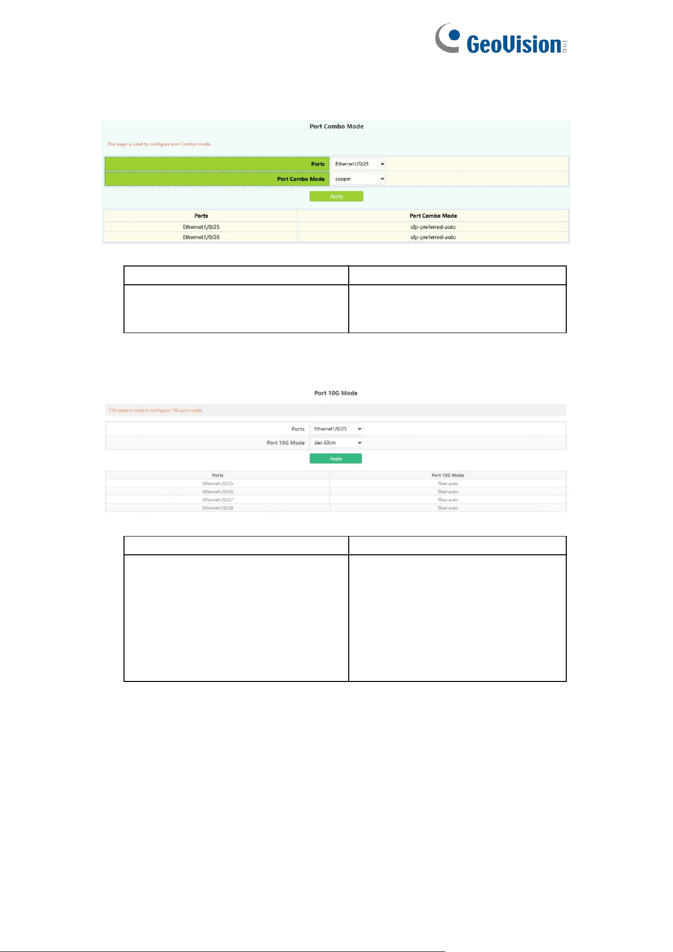
3.1.2.Port Combo Mode(Specific)
This page is mainly used to configure the basic of combo ports.
Port
Select physical ports
Port Combo Mode
copper: select copper
fiber: select fiber
sfp-preferred-auto: auto mode
3.1.3.Port 10G Mode(Specific)
This page is mainly used to configure the basic of 10G ports.
Port
Select physical ports
Port 10G Mode
dac-50cm: DAC 50cm
dac-100cm: DAC 100cm
dac-300cm: DAC 300cm
dac-500cm: DAC 500cm
fiber-10g: Fiber forced 10G
fiber-1g: Fiber forced 1G
fiber-2500M: Fiber forced 2500M
fiber-auto: Fiber Auto mode
37
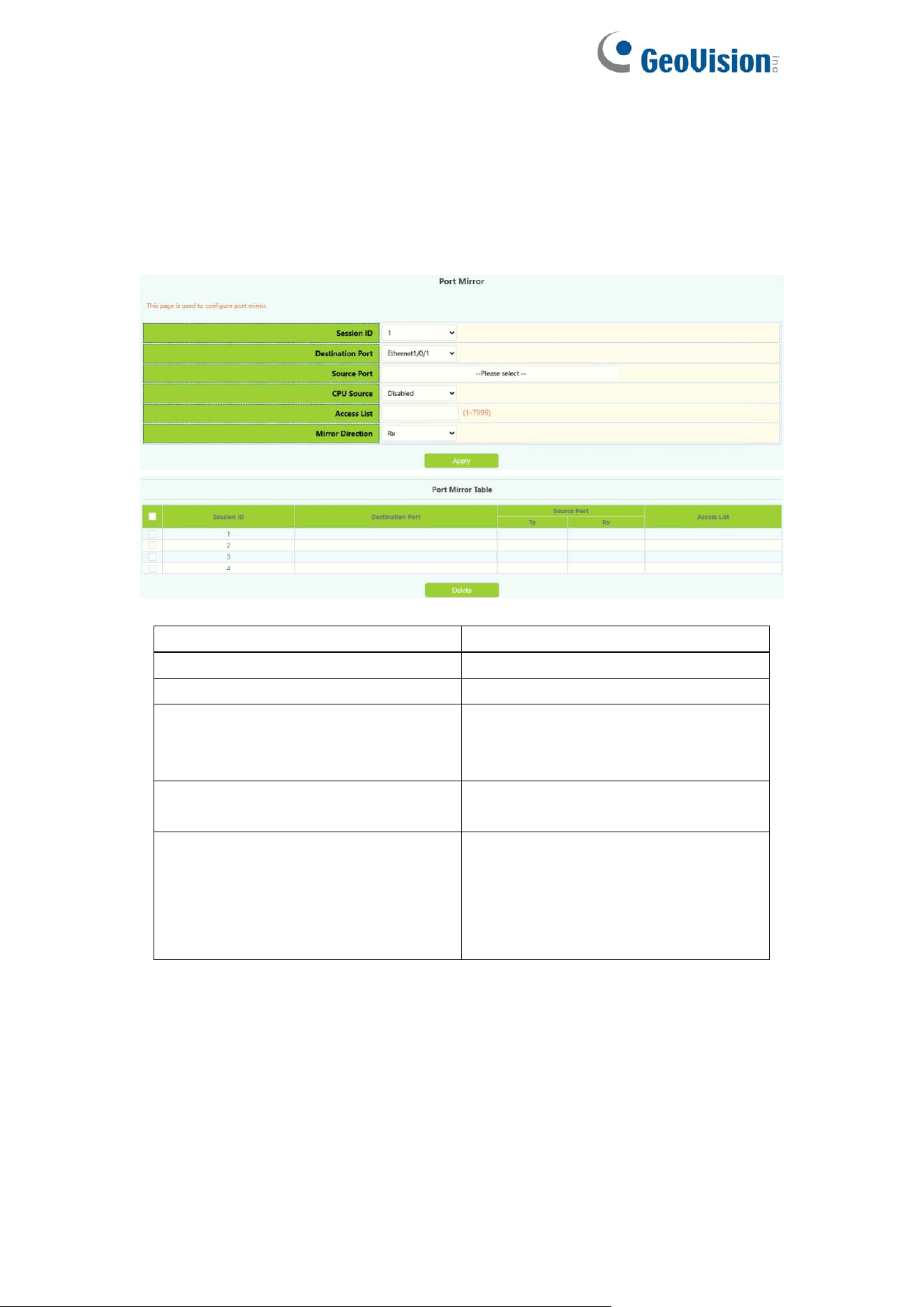
3.2.Port Mirror
This section can be used for port mirroring function configuration.
To display the “Port Mirror” page,click Switch Config ->Port Mirror,click
"Apply" to configure.
Session
Mirror Session
Destination port
Mirror destination port
Source port
Mirror Source Port
CPU Source
CPU Source:
Disabled
Enabled
Access list
The access control list set for the
mirror source port
Mirror direction
What kind of data is needed to filter
to the destination port:
Both:Sending and receiving
Rx: receive
Tx:send
38
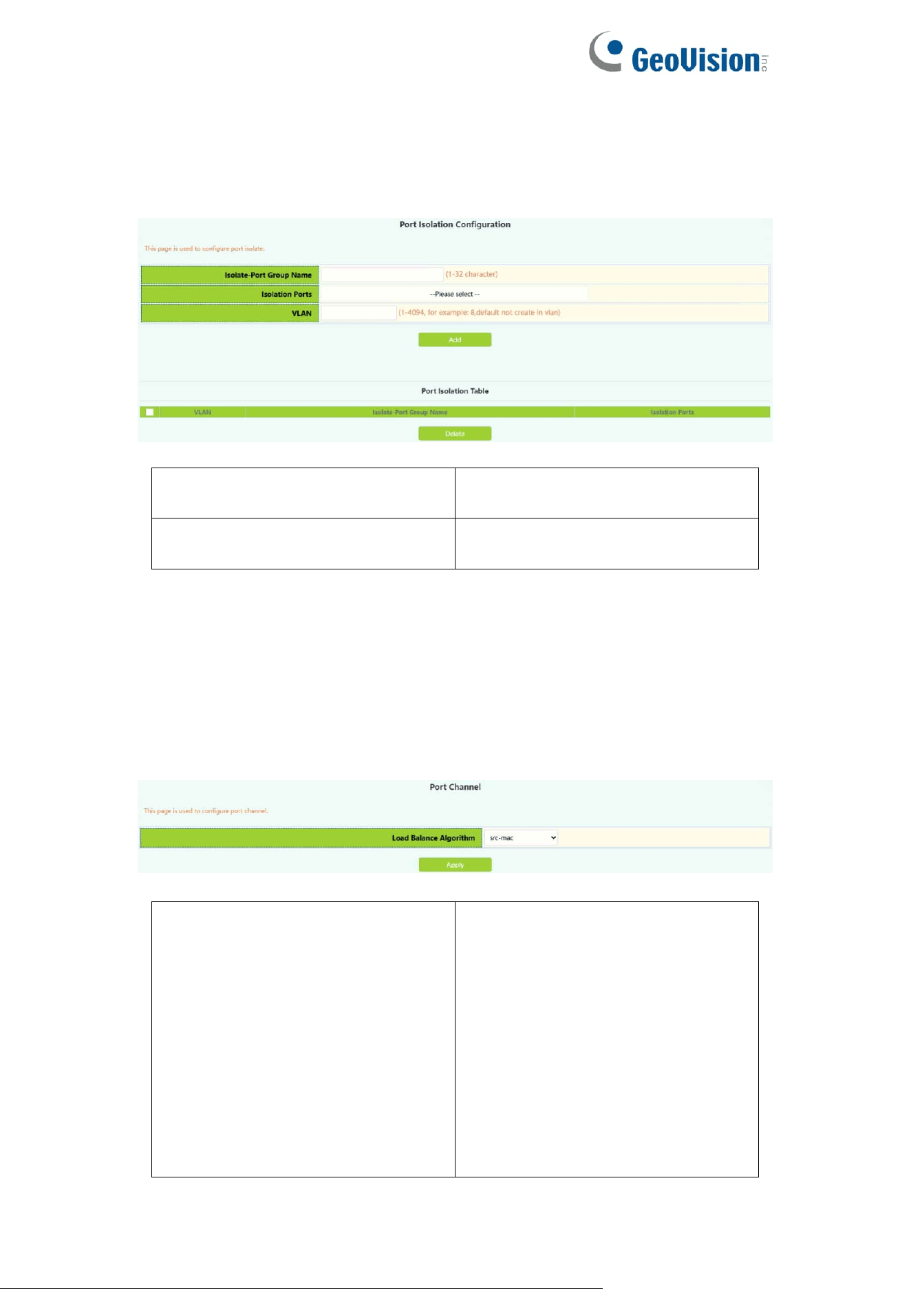
3.3.Port Isolate
This page is mainly used to configure the port isolation.
Isolate-Port Group Name
The name of isolate-port
Group,value 1-32 character
Isolation Ports
Select isolation ports to add isolate
group
3.4.Port Channel
3.4.1.Port Channel Group
This section can be used to create convergent groups.
To display the “Port Channel Group” page,click Port channel -> Port Channel
Group,click "Apply" to configure.
Load balance mode
src-mac:Execute load balancing
according to source MAC
dst-mac:Execute load balancing
according to target MAC
src-dst-mac : Execute load
balancing based on source and
target MAC
src-ip : Execute load balancing
according to source IP
dst-ip : Execute load balancing
according to target IP
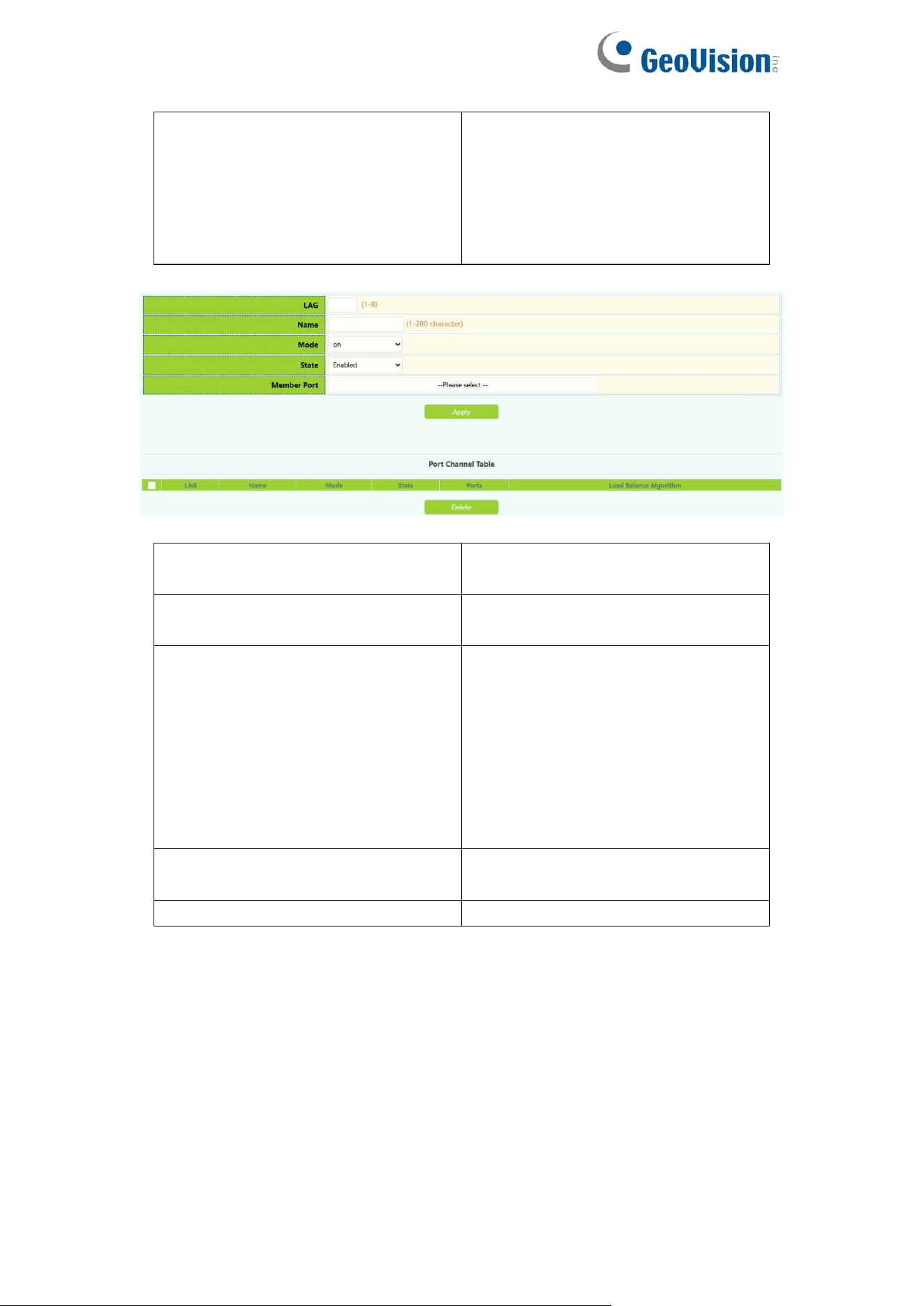
39
dst-src-ip:Execute load balancing
according to target IP source
dst-src-mac-ip : Perform load
balancing based on target and
source Mac and source IP
ingress-port :ingress port.
LAG
To create a convergent group
number, value 1-8.
Name
The name of LAG group, value
1-32 character
mode
On:force port to join port channel
without LACP. enabled
Active:Enable the LACP on the
port and set it to Active mode;
Passive:Enable LACP on the port
and set it to passive mode
State
Enabled
Disabled
Member Port
Ethernet port name
40
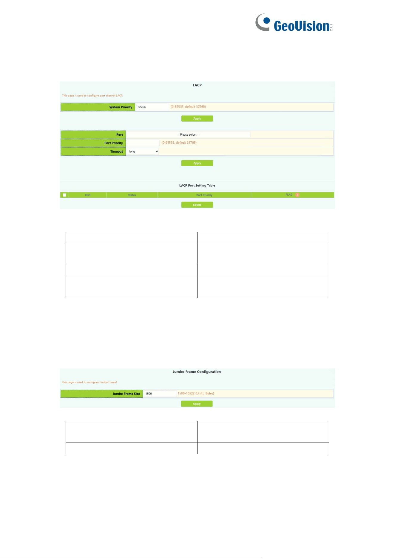
3.4.2.LACP
This page is available with setting system priority and port priority.
To display the “LACP” page,click Switch Config -> Port channel->LACP,
LACP system priority
Range :0-65535
Port list
Ethernet port name added to
convergence group
LACP port priority
Range :0-65535
Timeout
long
short
3.5.Jumbo Frame
This page is used to configure Jumbo Frame.
Status
Disabled(default)
Enabled
Jumbo Frame Size(Unit: Bytes)
Size 1500-12270,default is 1500.
41
3.6.Port Rate
The page is configured for Port Rate.
To display the “Port Rate” page,click Switch Config -> Port Rate,click
"Apply" to configure.
Ports
Ethernet port name
Limit Type
Limit type:
Egress:send
Ingress :receive
All:send and receive
Status
Disabled
Enabled
Rate
Bandwidth control rate in the range
of Kbps 1-1000000
Port
Ethernet port name
Ingress bandwidth threshold(Kb)
Displays the current received data
bandwidth limit in the range of
Kbps 1-1000000
Engress bandwidth
threshold(Kb)
Displays the bandwidth limit of the
current sending data, ranging from
1-1000000kbps
42
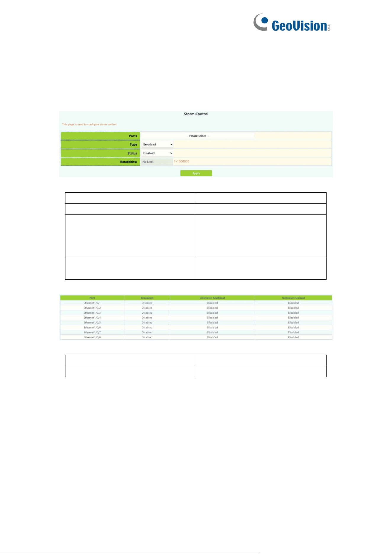
3.7.Storm Control
This page can be configured for the storm control function of the port.
To display the “Storm Control” page,click Switch Config -> Storm Control,click
"Apply" to configure.
Port
Ethernet port name
Type
Broadcast/Multicast/Unicast
Status
Disabled: Disable Storm Control
Enabled: Turn on the storm control
function and configure the speed
limit
Rate
storm control rate, ranging from
1-1000000 kbps or pps 1-1488095
Port
Ethernet port name
storm-control type
Broadcast/Multicast/Unicast
43
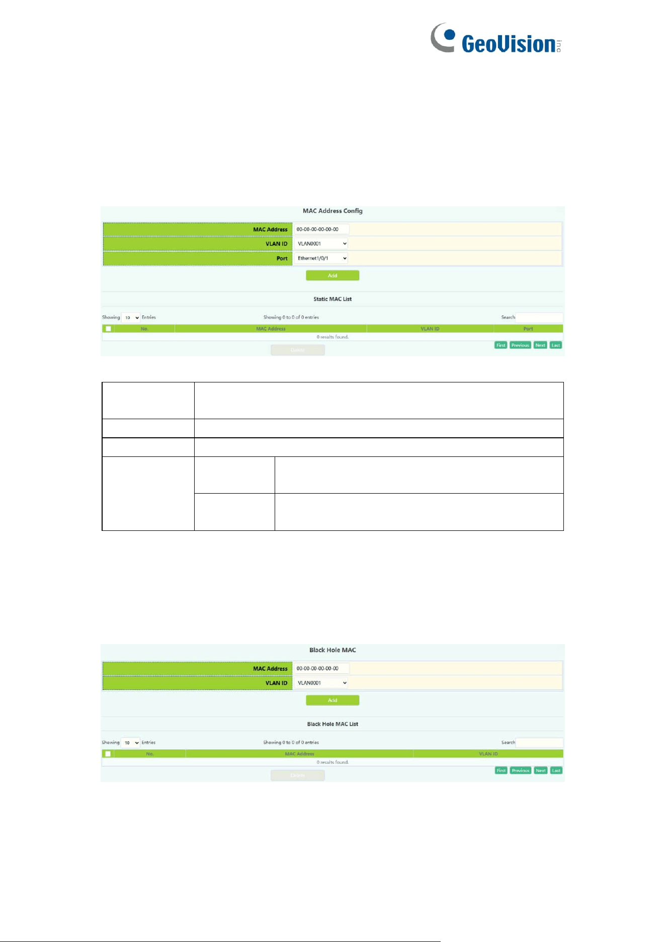
3.8.MAC Address Config
3.8.1.Static MAC
Configure Static MAC addresses, and establish the mapping relationship
between MAC addresses and ports and VLANs.
MAC
address
Hexadecimal MAC address, the format is xx-xx-xx-xx-xx-xx
VLAN ID
Created VLAN ID
Port
Mapped port
Operation
Add
The mapping relationship between MAC
address and port and VLAN will be added
Remove
Delete the mapping relationship of the specified
MAC address, VLAN, and port
3.8.2.Black Hole MAC
Configure Blackhole MAC addresses, and establish the mapping relationship
between MAC addresses and ports and VLANs.
44
MAC
address
Hexadecimal MAC address, the format is xx-xx-xx-xx-xx-xx,
packets with this address will be discarded and will not be
forwarded to the network by the switch
VLAN ID
Created VLAN ID
Blackhole
based type
source
Source based on source address filter
destination
Target based on target address filter
both
Both are based on source address and
destination address filters, the default value is
both
Operation
Add
The mapping relationship between MAC address
and port and VLAN will be added
Delete
Delete the mapping relationship of the specified
MAC address, VLAN, and port
Display current existing MAC address, port, VALN mapping relationship
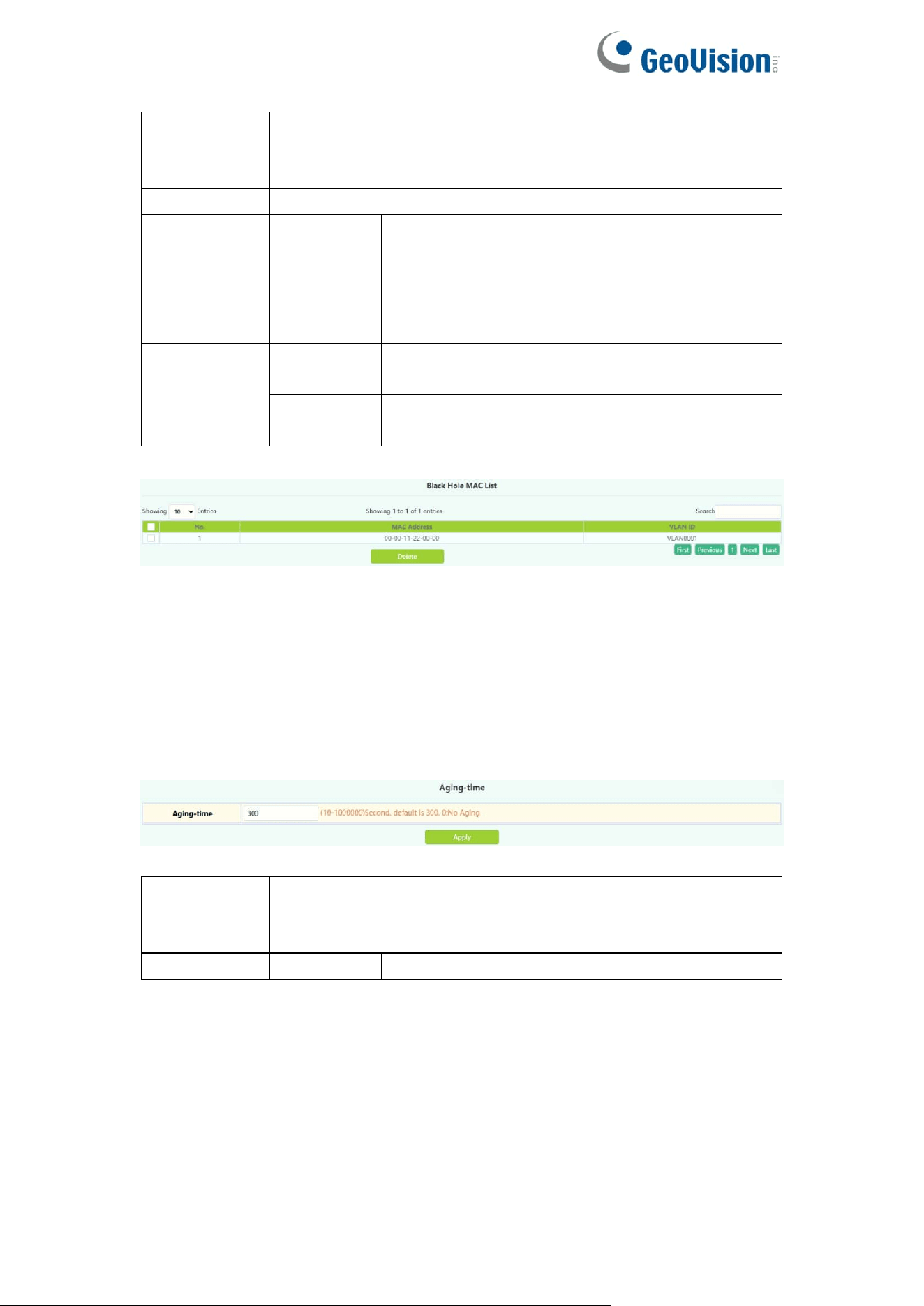
3.8.3.Aging-time
Each time the switch learns a MAC address, it will store the address and set
the aging time. When the time is over, the address will be removed from the
switch.
MAC
address
Aging-time
The aging time range is 10-1000000, 0 means no aging
Operation
Apply
Set the aging time into the switch
45
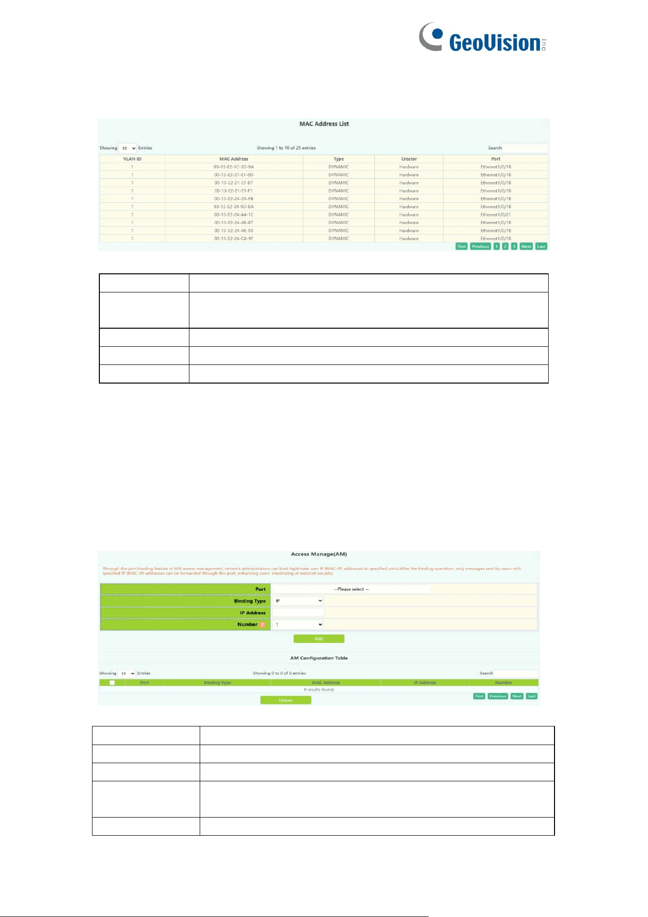
3.8.4.MAC Address List
Quickly query the MAC address in the switch.
VLAN ID
The created VLAN ID, showing the address in the VLAN
MAC
Address
Hexadecimal MAC address, the format is xx-xx-xx-xx-xx-xx
Type
MAC address type
Creator
MAC address creator
Port
Find the MAC address by port
Note: Check the small box at the back to make the condition take effect. By
default, there is no condition. When there is no condition, all MAC address
information will be displayed.
3.9.AM
AM module, the user can set up AM IP segment and MAC-IP segment on the
specified port, allowing / rejecting messages from within the segment to be
forwarded through the port.
Port
Designated port number
Binding Type
Select IP or MAC-IP method
IP address
Beginning IP address, decimal point
Number
Number of consecutive addresses after starting IP
address ,1-32
MAC address
Source MAC address
46
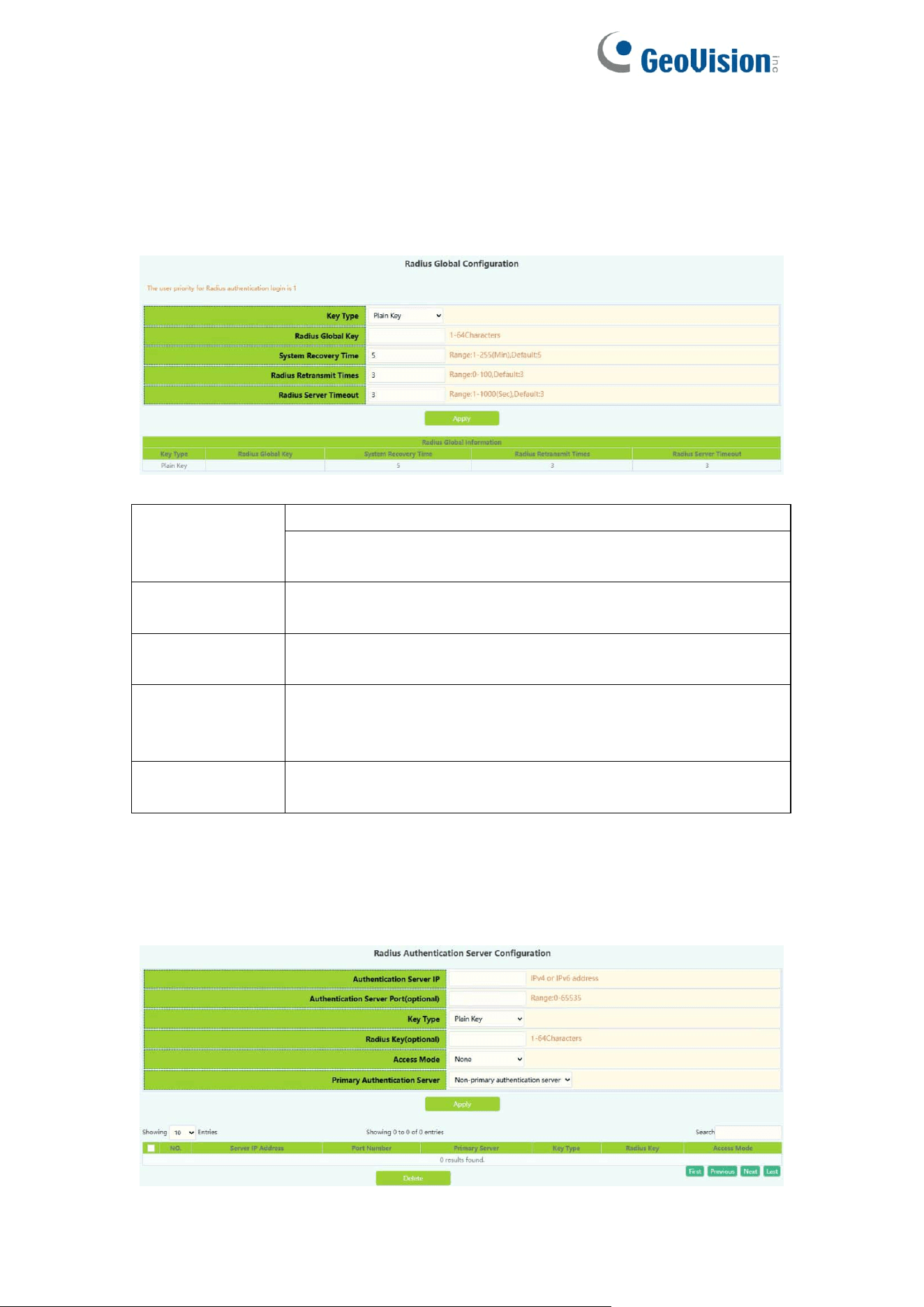
3.10.AAA
3.10.1.Radius
Radius Global Configuration module, users in this module can configure the
global Radius function services.
Key Type
Plain Key: 1-64 character
Cipher Key: 1-64 character, input plaintext application to
encrypt ciphertext.
Radius Global
Key
Key string ,1-64 characters, select Use default and click
Apply can set Radius Key default.
System
Recovery Time
Radius service recovery time from downtime to
accessibility, 1-255 minutes, default is 5.
Radius
Retransmit
Times
Radius authentication packet retransmission time, 1-100
seconds, default is 3.
Radius Server
Timeout
The corresponding time of the radius server, 1-1000
seconds, default is 3.
Radius Authentication Configuration module, users in this module can
configure the Radius authentication server.
47
Authentication
Server IP
The address of IPv4 or IPv6 of the radius authentication
server
Authentication
Server port
Port number of radius authentication
server(optional),0-65535
Key Type
Plain Key: 1-64 character
Cipher Key: 1-64 character, input plaintext application to
encrypt ciphertext.
Radius Key
Key string ,1-64 characters
Access Mode
None: All services can use current RADIUS server by
default
Telnet: RADIUS server only use telnet authentication
Dot1x: RADIUS server only use 802.1x authentication
Wireless: RADIUS server only use wireless
authentication
Primary
Authentication
Server
Primary
authentication
server
Specify radius server as primary
authentication server
Non-Primary
authentication
server
Specify radius server as non-primary
authentication server
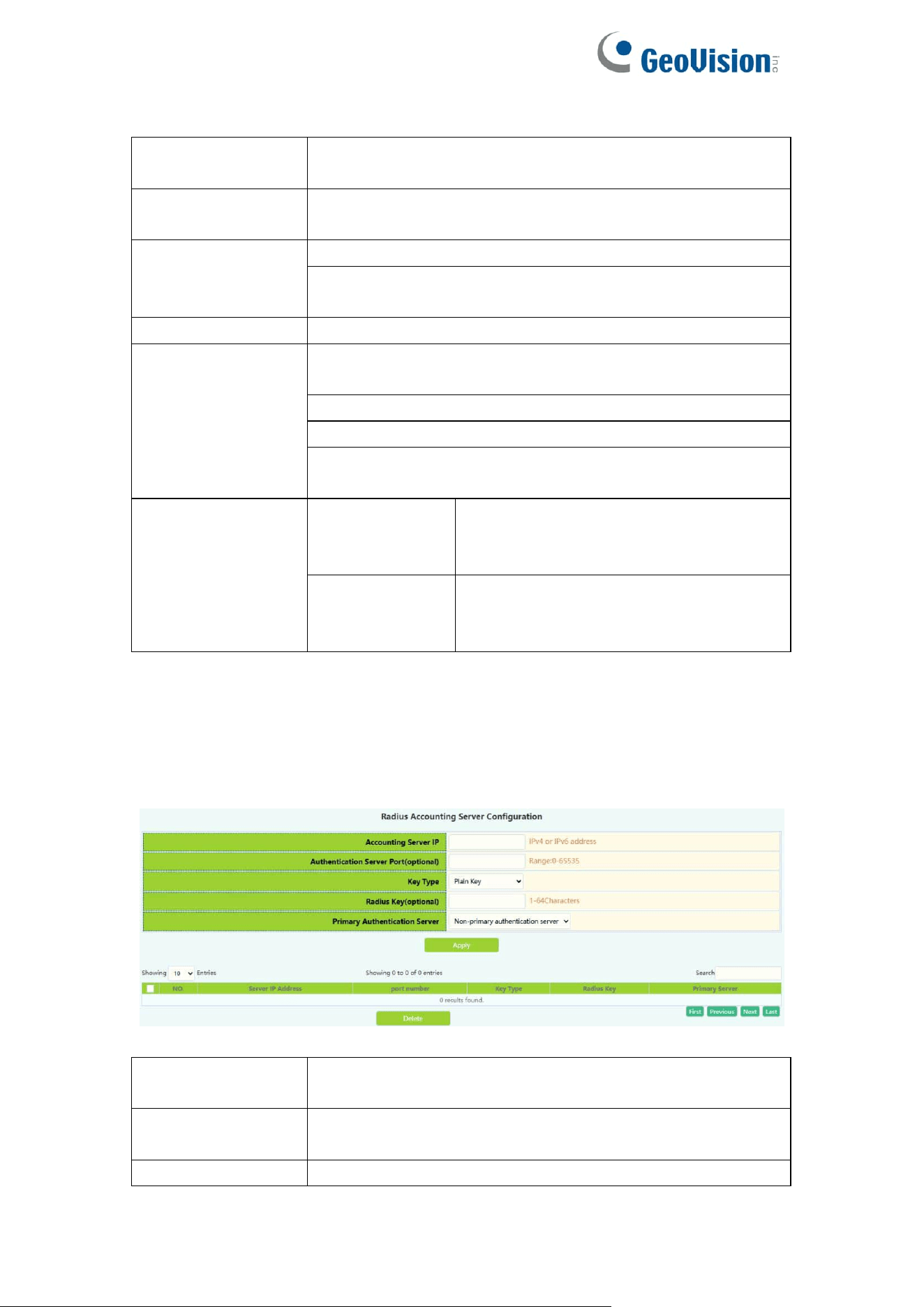
3.10.2.Radius Accounting
Radius authentication and accounting module, users in this module can
configure the Radius billing server.
Accounting
Server IP
Radius authentication server IPv4 or IPv6 address
Accounting
Server Port
Radius authentication server port number
(optional),0-65535
Key Type
Plain Key: 1-64 character
48
Cipher Key: 1-64 character, input plaintext application to
encrypt ciphertext.
Radius Key
Key string ,1-64 characters
Primary
Accounting
Server
Primary
accounting
server
Specify radius server as primary
accounting server
Non-Primary
accounting
server
Specify radius server as non-primary
accounting server
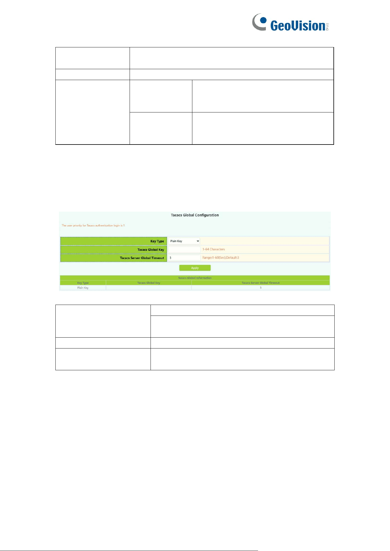
3.10.3.Tacacs
Tacacs global configuration module, users in this module can configure the
global Tacacs function services.
Key Type
Plain Key: 1-64 character
Cipher Key: 1-64 character, input plaintext
application to encrypt ciphertext.
Tacacs Global Key
Tacacs authentication global key ,1-64 characters
Tacacs Server Global
Timeout
Tacacs authentication timeout ,1-60 seconds,
default 3 seconds
49
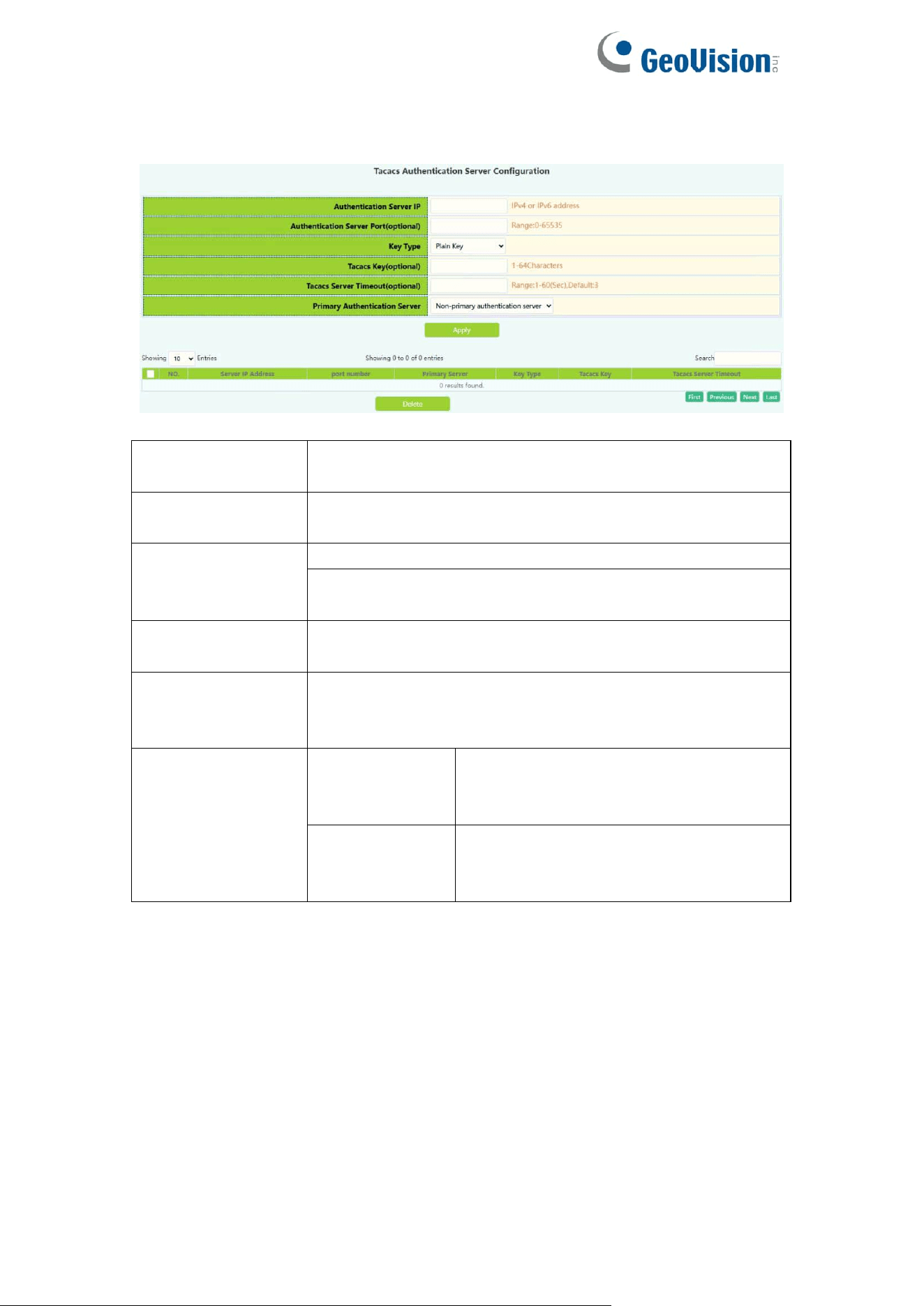
Tacacs server configuration module, users in this module can configure the
Tacacs authentication server.
Authentication
Server IP
Tacacs authentication server IPv4 address, decimal point
Authentication
Server Port
Tacacs authentication server port number
(optional),0-65535
Key Type
Plain Key: 1-64 character
Cipher Key: 1-64 character, input plaintext application to
encrypt ciphertext.
Tacacs Key
Configure tacacs+ server encryption key
1-64 Characters
Tacacs Server
Timeout
Configure the tacacs+ server authentication time
Interval <1-60> second
Deafult is 3.
Primary
Authentication
Server
Primary
accounting
server
Specify Tacacs server as primary
accounting server
Non-Primary
accounting
server
Specify Tacacs server as non-primary
accounting server
50
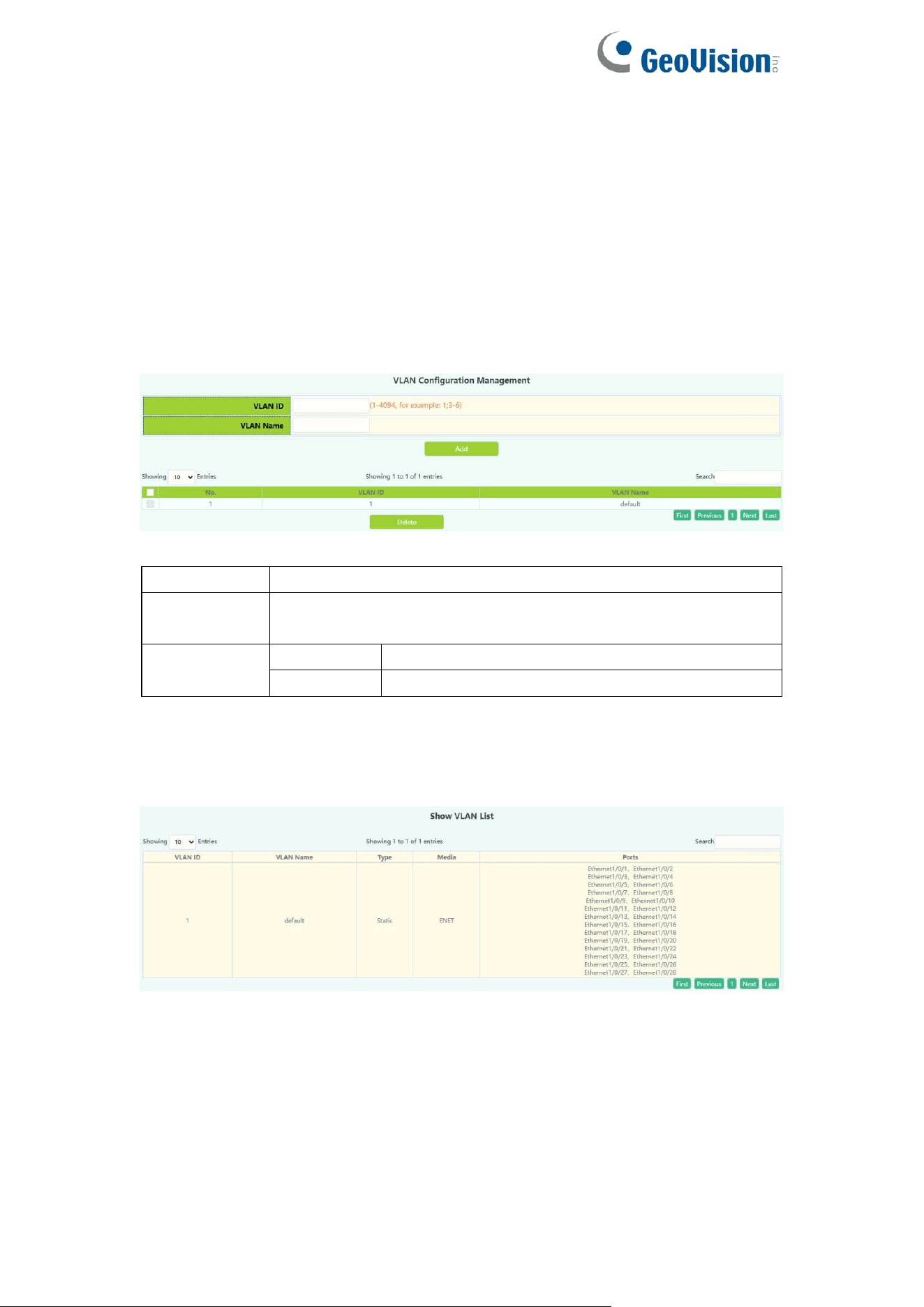
4.VLAN Config
4.1.VLAN Config
4.1.1.VLAN ID
VLAN configuration function module, users add or delete VLANs in this
module。
VLAN ID
The serial number of the VLAN, range: 2-4094
VLAN name
By default, the default is VLAN plus four-digit serial number,
range: 1-64 characters.
Operation
Add
Add VLAN
Delete
Remove VLAN
4.1.2.Show VLAN
Show VLAN function module, display VLANs in this module。
51
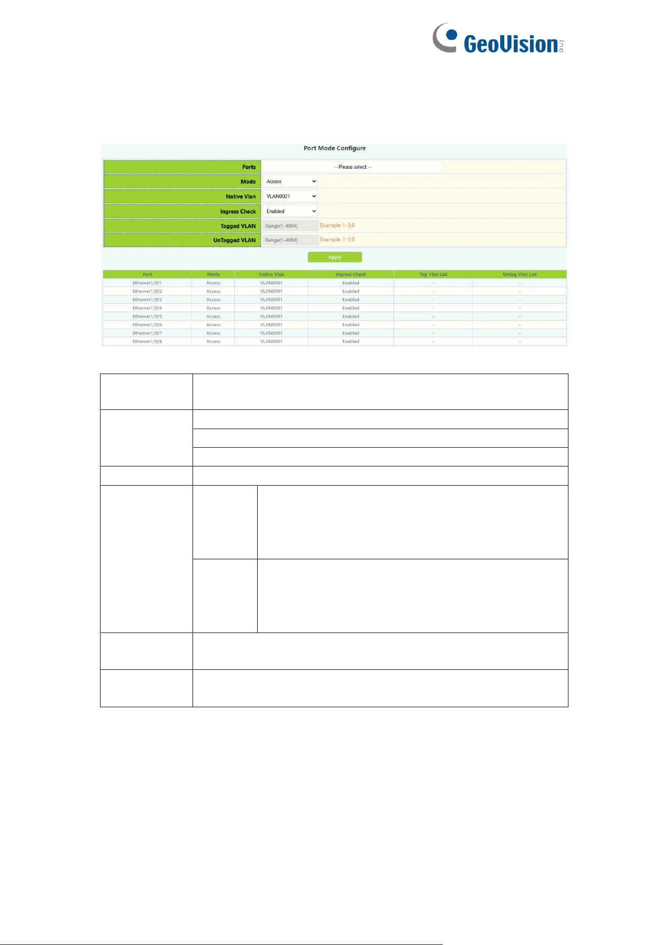
4.1.3.Port Config
Switch port type setting, the user can change the switch port type in this
module.
Port
Port name
Mode
Access
Trunk
Hybrid
Native Vlan
Port PVID
Ingress
Check
Enabled
When a data packet enters the switch, the VLAN
ingress filter checks whether the ingress port of
the data packet belongs to the given (forwarded)
VLAN
Disabled
When a data packet enters the switch, the VLAN
ingress filter does not check whether the ingress
port of the data packet belongs to the given
(forwarded) VLAN
Tagged
VLAN
Tag VLAN range 1-4094,example 1-3;8
UnTagged
VLAN
Untag VLAN range 1-4094,example 1-3;8
52
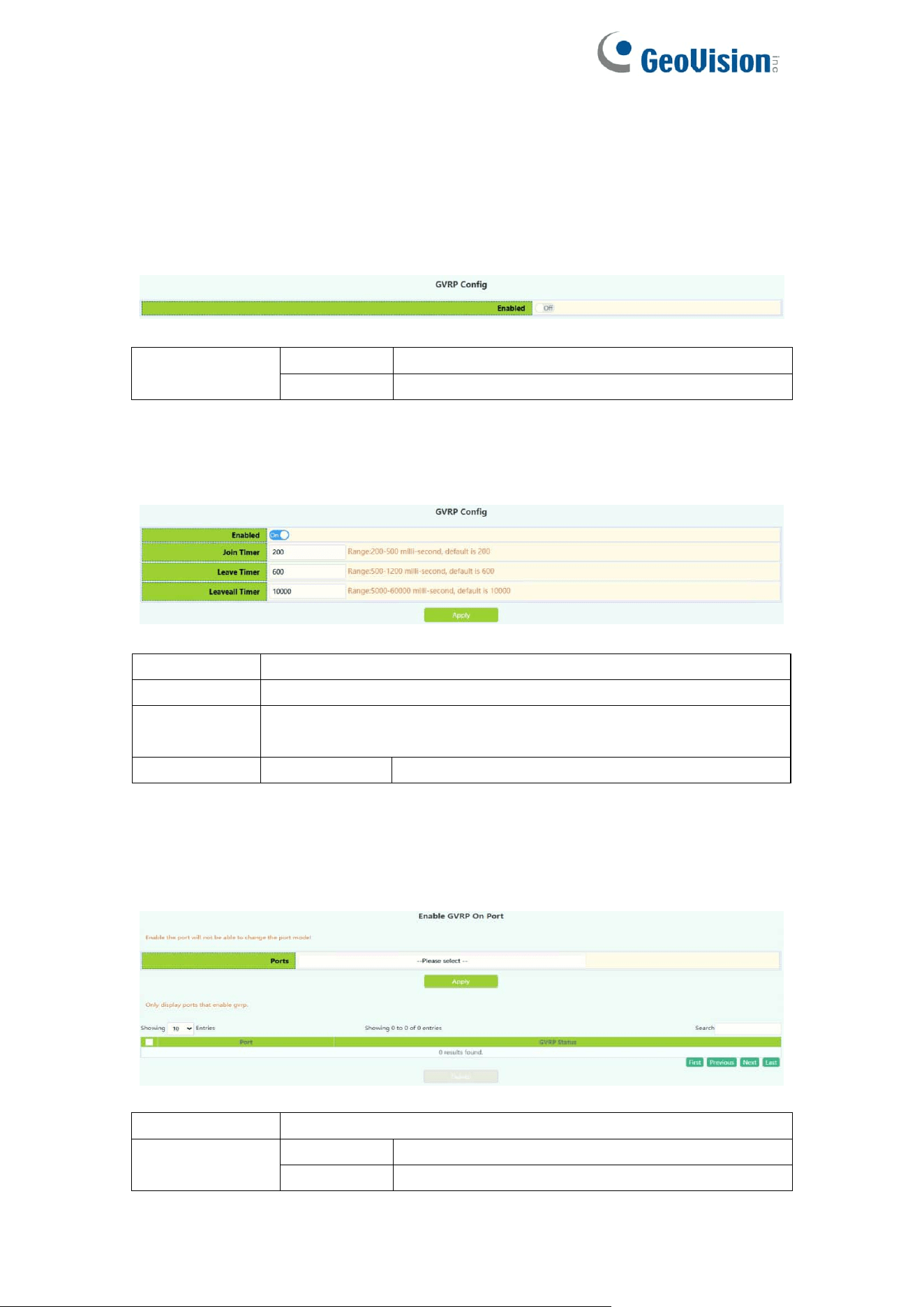
4.2.GVRP Config
4.2.1.GVRP Config
The switch starts the global GVRP setting, and the user turns on or off the
global GVRP.
Enable/Disable
global GVRP
Enable
Start the global GVRP module function
Disable
Disable the global GVRP module function
The switch configures GARP parameters, and the user sets the value of
various timers to manage GARP.
Join timer
200-500ms
Leave timer
500-1200ms
Leaveall
timer
500-60000ms
Operation
Apply
Modify the value of the timer
4.2.2.GVRP Port
The switch port starts GVRP settings, and the user opens or closes the port
GVRP.
Port
Port name
Enable/Disable
GVRP
Enable
Start the port GVRP module function
Disable
Disable the port GVRP module function
53
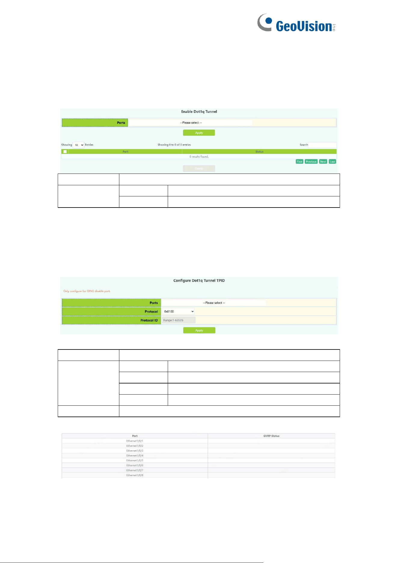
4.3.QINQ
4.3.1.Enable Dot1q Tunnel
Switch dot1q tunnle configuration, the user configures the port to enable the
dot1q tunnel function.
Port
Port name
Operation
Apply
Enable
dot1q tunnel
Delete
Disable
dot1q tunnel
4.3.2.Dot1q Tunnel TPID
Switch port dot1q tunnle tpid configuration, users configure port dot1q tunnel
tpid parameters.
Port
Port name
Protocol
0x8100
Set the outer TPID to 0x8100
0x9100
Set the outer TPID to 0x9100
0x9200
Set the outer TPID to 0x9200
protocol ID
Set a custom TPID
Protocol ID
The value of the custom TPID
54
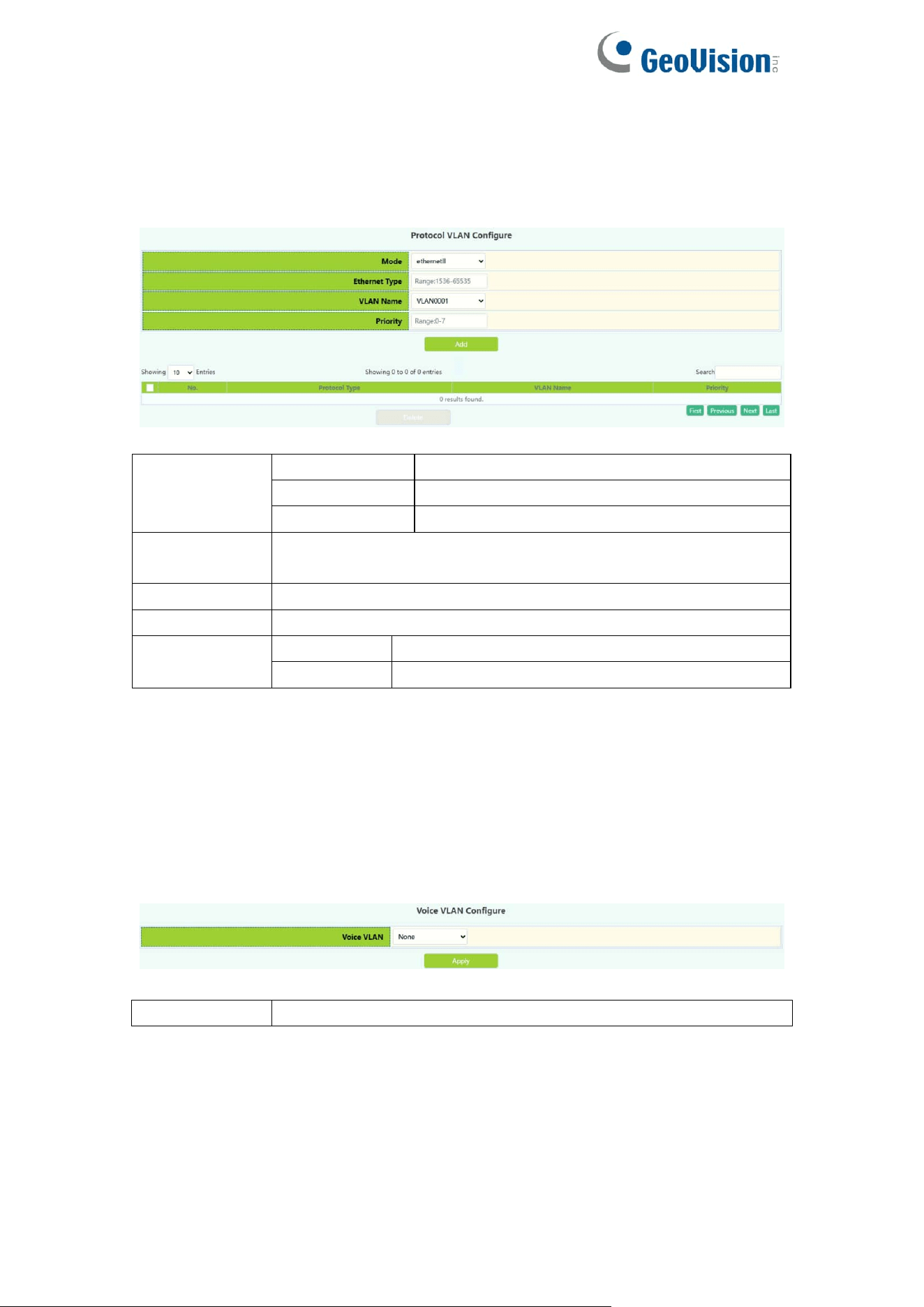
4.4.Protocol VLAN
The switch protocol vlan settings, and the user can config the protocol vlan.
Mode
ethernetII
Configure EthernetII Encapsulation
snap
Configure LLC Encapsulation
llc
Configure SNAP Encapsulation
Ethernet
Type
Packet protocol type, Configure Packet protocol type number,
1536-65535
VLAN Name
Configure the VLAN ID.
Priority
Configure priority value, 0-7
Operation
Add
Add the protocol vlan
Delete
Delete the protocol vlan
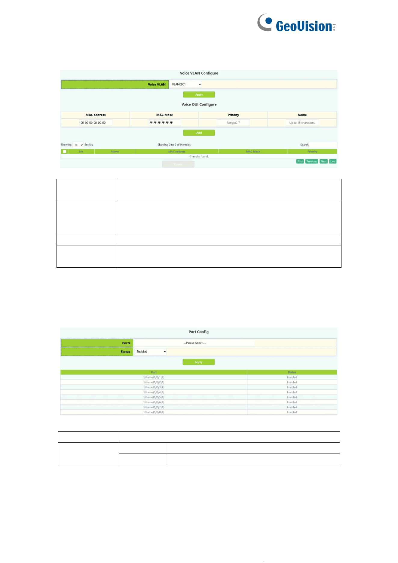
4.5.Voice VLAN
4.5.1.VLAN Config
The voice vlan configure module, and the user can select vlan to enable voice
vlan
Voice VLAN
Select vlan to enable voice vlan
55
The voice oui configure module, and the user can set voice oui
MAC address
The voice equipment MAC address, shown in
xx-xx-xx-xx-xx-xx format.
MAC Mask
The last eight digit of the mask code of the MAC address, the
valid values are: 0xff, 0xfe, 0xfc, 0xf8, 0xf0, 0xe0, 0xc0,0x80,
0x0
Priority
The priority of the voice traffic, the valid range is 0–7
Name
The voice-name is the name of the voice equipment, which is
to facilitate the equipment management
4.5.2.Port Config
The voice vlan port config module, and the user can select port to enable voice
vlan
Port
Port name
Status
Enable
Enable
voice vlan
Disable
Disable voice vlan
56
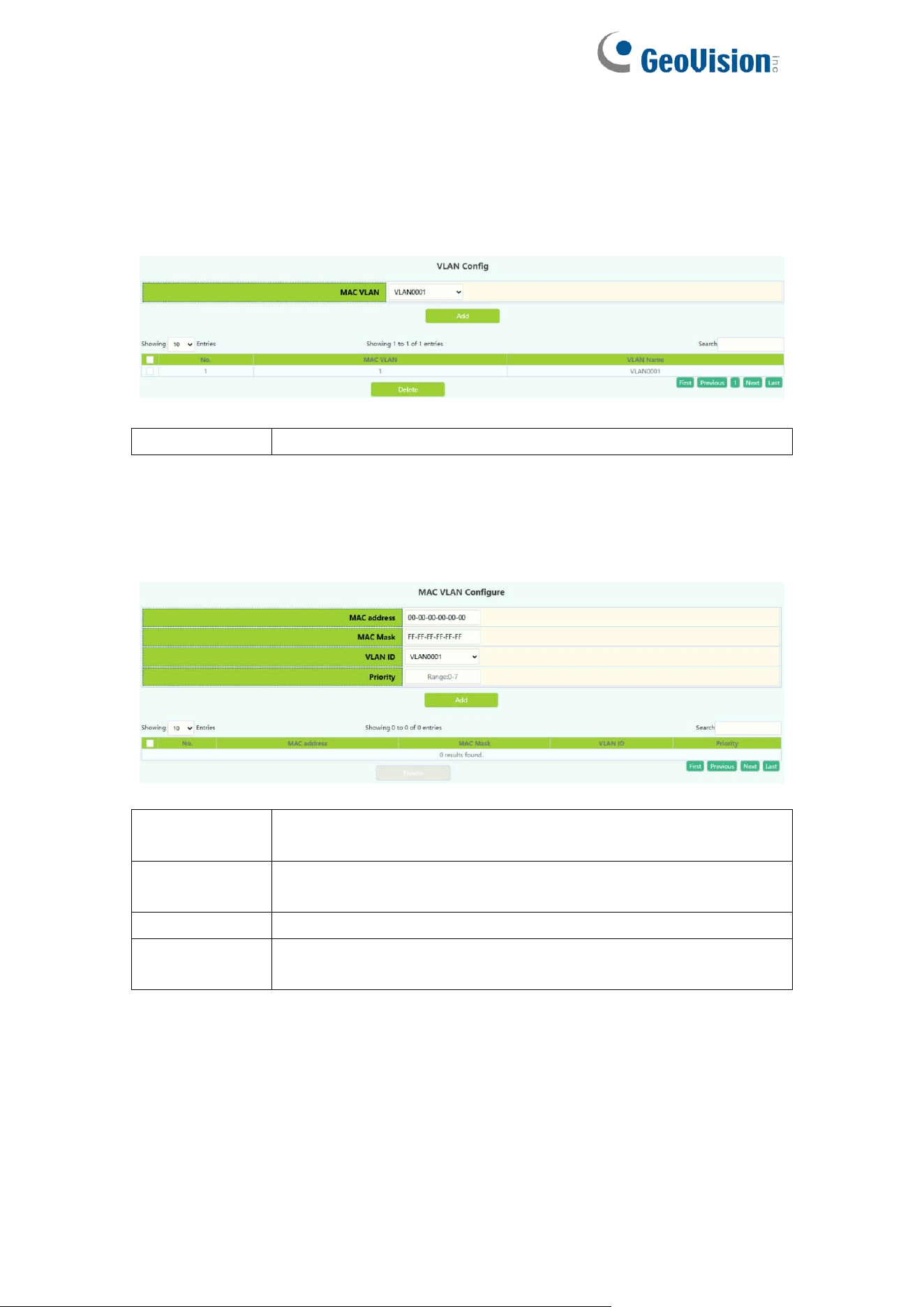
4.6.MAC VLAN
4.6.1.VLAN Config
The mac vlan configure module, and the user can select vlan to add mac vlan
MAC VLAN
Select vlan to add mac vlan
4.6.2.VLAN Member
the user can set mac vlan
MAC address
The MAC address which is shown in the form of
XX-XX-XX-XX-XX-XX
MAC Mask
The MAC address mask which is shown in the form of
XX-XX-XX-XX-XX-XX
VLAN ID
Vlan-id is the ID of the VLAN with a valid range of 1-4094
Priority
Priority-id is the level of priority and is used in the VLAN tag
with a valid range of 0-7
57
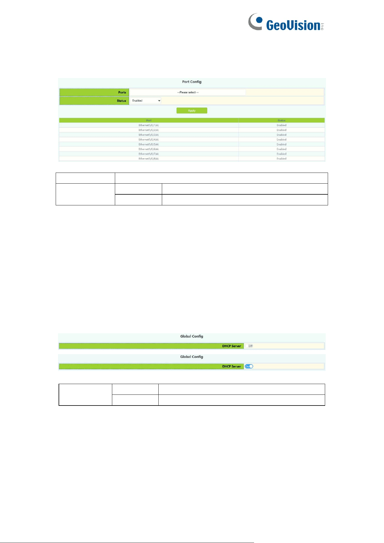
4.6.3.Port Config
The mac vlan port config module, and the user can select port to enable mac
vlan
Port
Port name
Status
Enable
Enable mac
vlan
Disable
Disable mac vlan
5.DHCP Config
5.1.DHCP Server
5.1.1.Global Config
DHCP status configuration and query, the user configures the DHCP server
status in this module, and checks the DHCP server status
DHCP
server
Off
Close DHCP server
On
Open DHCP server
58
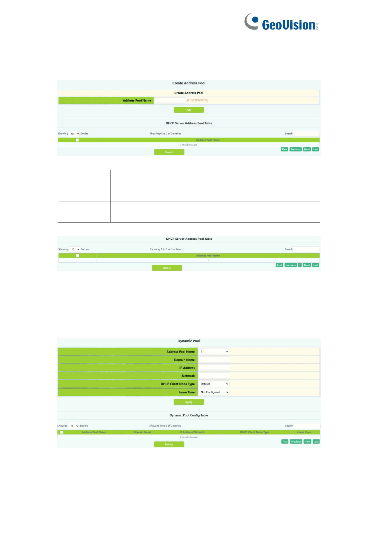
5.1.2.Create Address Pool
DHCP server address pool name configuration, user settings add and delete
the address pool name.
DHCP
Address
pool name
The name of the created address pool
Operation
type
Add pool
Add the address pool of the DHCP server
Delete
Delete the address pool of the DHCP server
Display the address pool of the current DHCP server
5.1.3.Dynamic Pool
Switch DHCP address pool configuration, the user configures the DHCP
address pool parameters.
59
DHCP pool
name
The name of the created address pool
DHCP pool
domain
name
The domain name of the currently selected address pool.
After configuration, you need to tick the box at the back to
apply the domain name to the switch during application.
Address
range
IP address
Network number of the address pool
Network
mask
Netmask of the address pool
DHCP client
node type
b-node
Broadcast node
p-node
For point-to-point nodes
m-node
Used for hybrid nodes to perform
point-to-point communication after
broadcasting
h-node
Hybrid nodes that broadcast after peer-to-peer
communication
Designate
Hexadecimal node type, from 0 to 255
Address
lease
timeout
Infinite
The lease period of the address is unlimited,
and the number of days/hours/minutes below
do not need to be filled in
Specified
There is a time limit for the lease of the
address. You can rent it according to the lease
time filled in below, and it will be automatically
recovered if the time is exceeded
Operation
add
Add the above four parameters with check
boxes to the switch, the parameters without
check boxes will not be operated
Delete
Restore the four parameters with check boxes
to the default configuration, and the
parameters without check boxes will not be
operated
Information display of the currently configured address pool
60
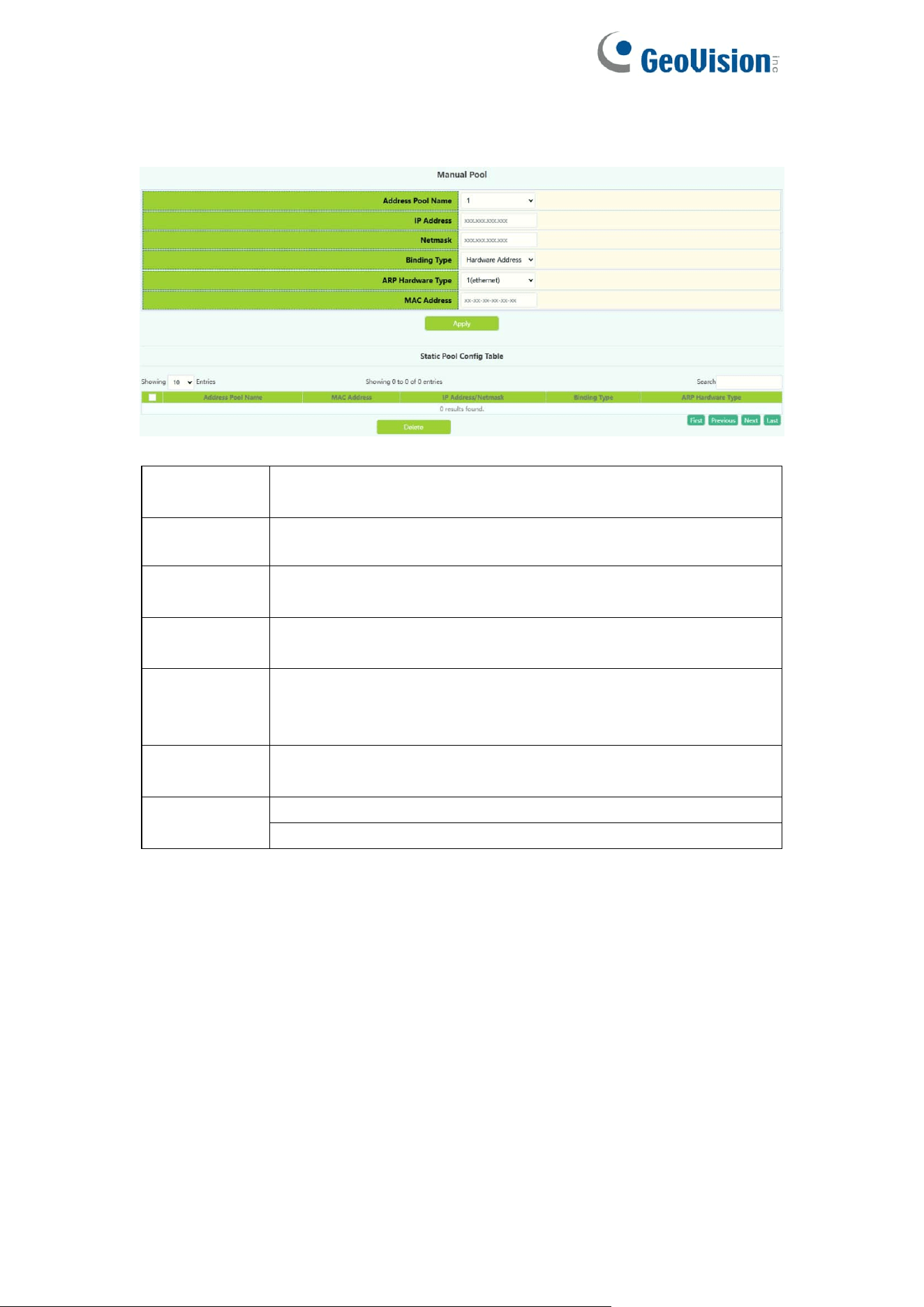
5.1.4.Manual Pool
Switch static address pool configuration, and manually bind client parameters.
Address
Pool Name
The name of the created address pool
IP address
IP address assigned by the DHCP server to the client
Netmask
The subnet mask assigned by the DHCP server to the client
IP
Binding
Type
Hardware Address
Client identifier: The identifier of the client,
ARP
Hardware
Type
The protocol type used by the client is rfc\ethernet\ieee802.
RFC ID: RFC protocol number, valid range is 1-255.
MAC
address
MAC address,for example: 44-11-22-33-44-55 (MAC
address)
Operation
Apply
Delete
61
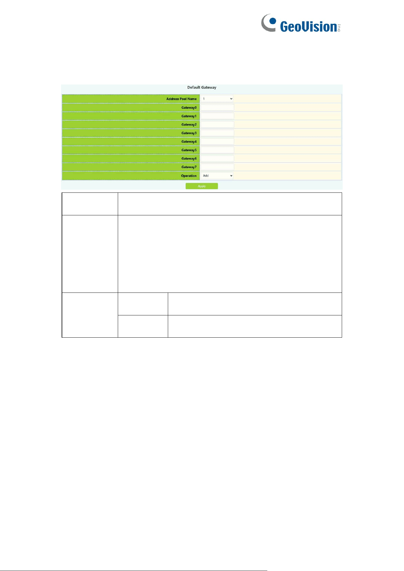
5.1.5.Default Gateway
The switch DHCP client default gateway configuration, the user configures the
gateway parameters of the DHCP address pool.
DHCP pool
name
The name of the created address pool
Gateway0-7
Gateway IP address in dotted decimal format. Gateway 0
has the highest priority. The smaller the number, the higher
the priority. The gateway can be set to zero or more, but the
setting must start with 0 and no vacancies can appear in the
middle, otherwise the gateway will be Ignore the following
parameters, such as setting gateway 0-1 and gateway 7,
only gateway 0-1 takes effect
Operation
Add
Add the gateway effectively set above to the
currently selected DHCP address pool
Delete
Clear all gateways and restore to the default
state
62
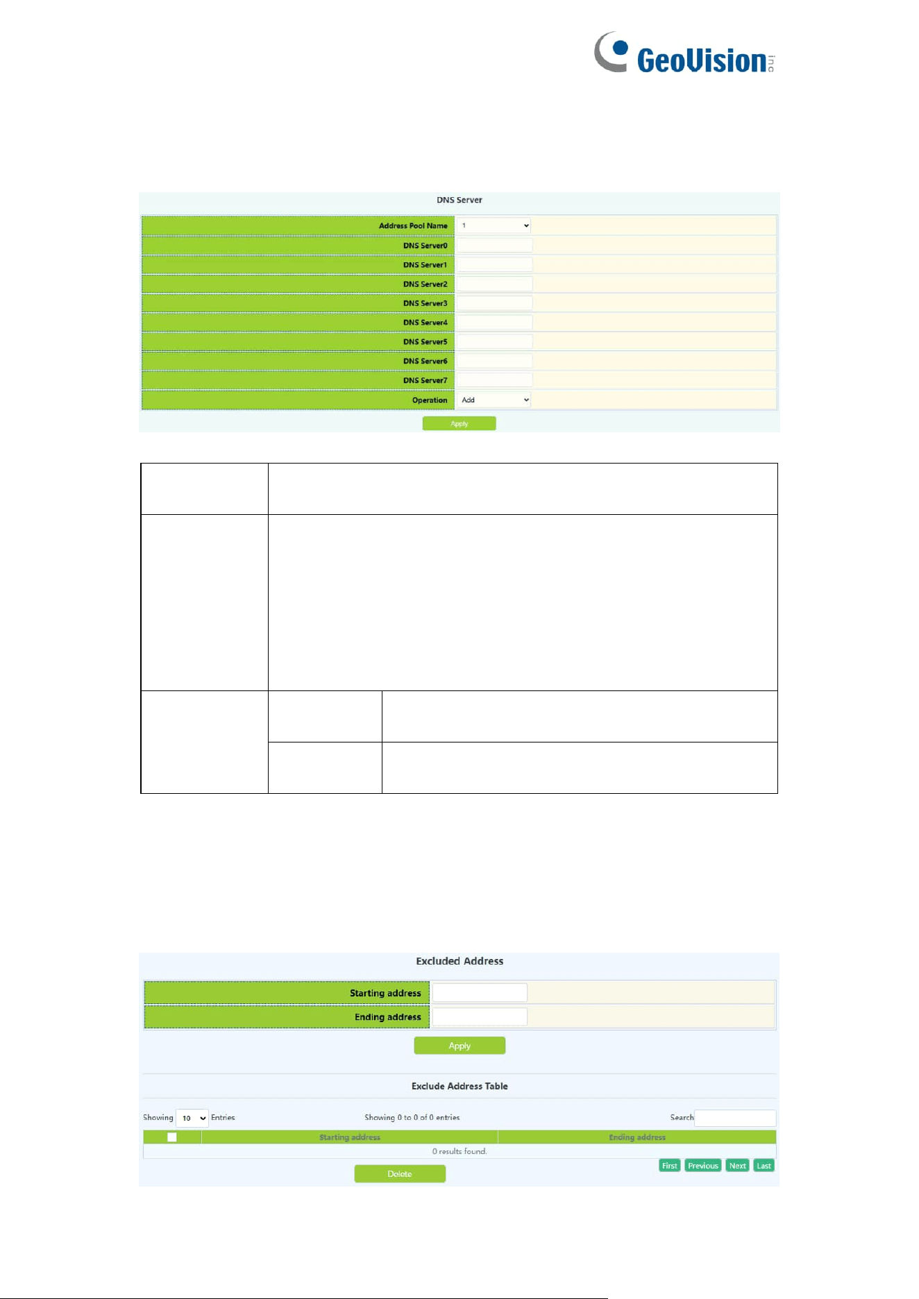
5.1.6.DNS Server
The switch DHCP client DNS server configuration, the user configures the
DNS server parameters of the DHCP address pool.
DHCP pool
name
The name of the created address pool
DNS server
0-7
For the IP address in dotted decimal format, DNS server 0
has the highest priority. The smaller the number, the higher
the priority. The DNS server can be set to zero or more, but
the setting must start from 0 and there can be no vacancies
in the middle, otherwise the DNS server The following
parameters will be ignored, such as setting DNS server 0-1
and DNS server 7, only DNS server 0-1 takes effect
Operation
Add
Add the DNS server effectively set above to
the currently selected DHCP address pool
Delete
Clear all DNS servers and restore to the
default state
5.1.7.Excluded Address
Excluding the dynamic allocation address configuration, the user configures
the addresses that are not used for dynamic allocation
63
Starting
address
Start address not used for dynamic allocation
Ending
address
End address not used for dynamic allocation
Operation
type
Apply
Add the address range that is not used and
dynamically allocated to the switch
Delete
Delete the address range that is not used and
dynamically allocated from the switch
Display the address range currently not used for dynamic allocation
5.1.8.Packet Statistics
DHCP server data packet statistics, users can view DHCP data packets.
It can be viewed in real time by clicking "Clear Statistics"
64
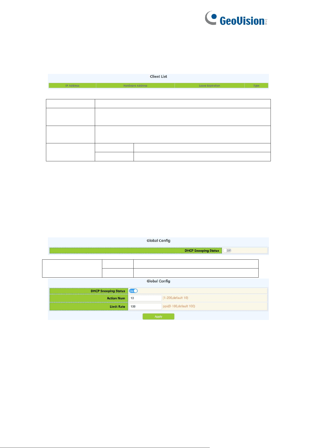
5.1.9.Client List
The DHCP server's IP and MAC binding status, the user can view the binding
entries and the relationship between the bound IP and MAC.
IP address
Client's IP address
Hardware
address
The hardware address or MAC address of the client
Lease
expiration
Client IP expiration time
Type
Manual
Manual binding
Dynamic
Dynamic allocation
5.2.DHCP Snooping
5.2.1.Global Config
With the enabling and disabling of the DHCP Snooping module, users can
view and operate the status of DHCP Snooping.
DHCP Snooping
status
Off
Disable DHCP Snooping
On
Enable DHCP Snooping
Display the current DHCP Snooping status
DHCP Snooping defense action number configuration, if the number of
alarm messages is greater than the set number, it will force the restoration of
the earliest defense measures to send new defense measures.
DHCP Snooping packet receiving rate limit sets the number of DHCP
messages sent per second.
65
DHCP Snooping
action Num
Set the maximum number of defense actions to
avoid exhaustion of switch resources caused by
attacks.
Limit Rate(Packet
per second)
Range: 0-100
Operation
Apply
Configure the number of defense actions
filled in above, default is 10,
Configure the number of packets per
second
Display the current number of DHCP Snooping defense actions
Display the number of packets per second configured for the current
DHCP Snooping.
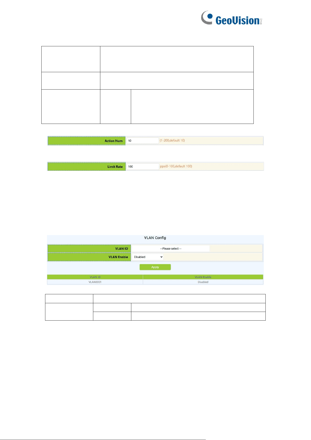
5.2.2.VLAN Config
With the enabling and disabling of the DHCP Snooping VLAN module, users
can view and operate the status of DHCP Snooping VLAN.
Port
Port name
VLAN Enable
Enable
Enable
DHCP Snooping VLAN
Disable
Disable
DHCP Snooping VLAN
66
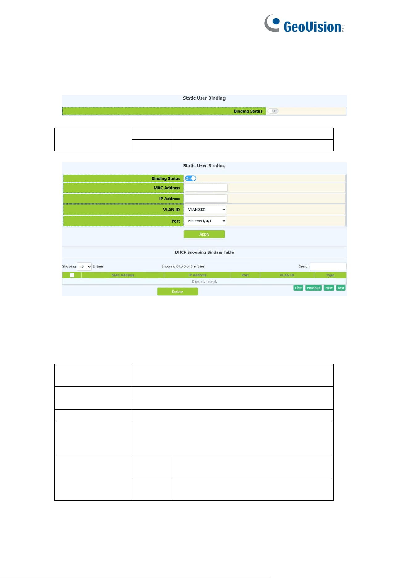
5.2.3.Static User Binding
When DHCP Snooping binding is enabled and disabled, users can view and
operate the status of DHCP Snooping. When configuring this binding, users
must ensure that the binding status is in the on state.
DHCP Snooping
binding status
Off
Disable DHCP Snooping binding function
On
Enable DHCP Snooping binding function
Shows whether the current DHCP Snooping binding status function is enabled.
When DHCP Snooping binding is enabled and disabled, users can view and
operate the status of DHCP Snooping. When configuring this binding, users
must ensure that the binding status is in the on state.
MAC address
The MAC address of the statically bound user is the
only index of the bound user
User IP address
Statically bind the user's IP address
User mask
Statically bind the user's subnet mask
VLAN ID
Statically bind the VLAN ID of the user
Port
Bind the user's access port statically, the port is
associated with the VLAN ID, and the port is required
to allow the VLAN to pass
Operation
Apply
Add DHCP Snooping binding user
relationship
Delete
Delete DHCP Snooping binding user
relationship
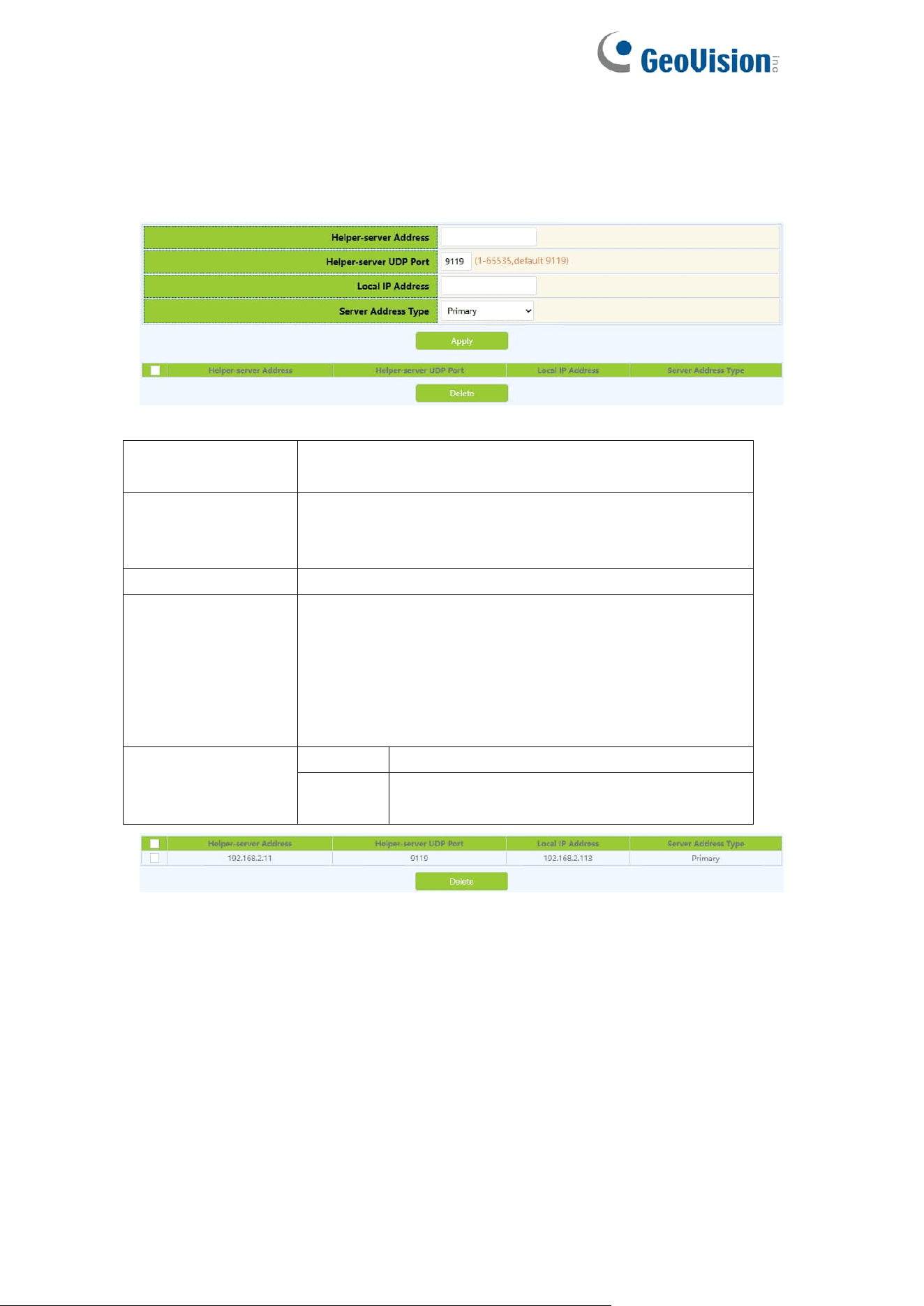
67
5.2.4.Helper-server Config
DHCP SNOOPING will send the monitored binding information to HELPER
SERVER for storage. If the switch starts abnormally, you can recover the
bound data from the HELPER SERVER
Helper-server
address
HELPER server address
Helper-server
UDP port
DHCP SNOOPING and HELPER SERVER use UDP
protocol for communication, the port range is
1-65535.
Local IP address
The effective management IP address of the switch
Second address
Two HELPER server addresses are allowed, DHCP
SNOOPING will first try to connect to the PRIMARY
server. Only when the PRIMARY server cannot be
accessed, the switch HELPER server will connect to
the SECONDARY server. Set the PRIMARY server
before setting up the SECONDARY server.
Operation
Apply
Add HELPER server address
Delete
Delete the HELPER server address, you
can leave it blank when deleting
Display the process and error messages or results generated during
application execution
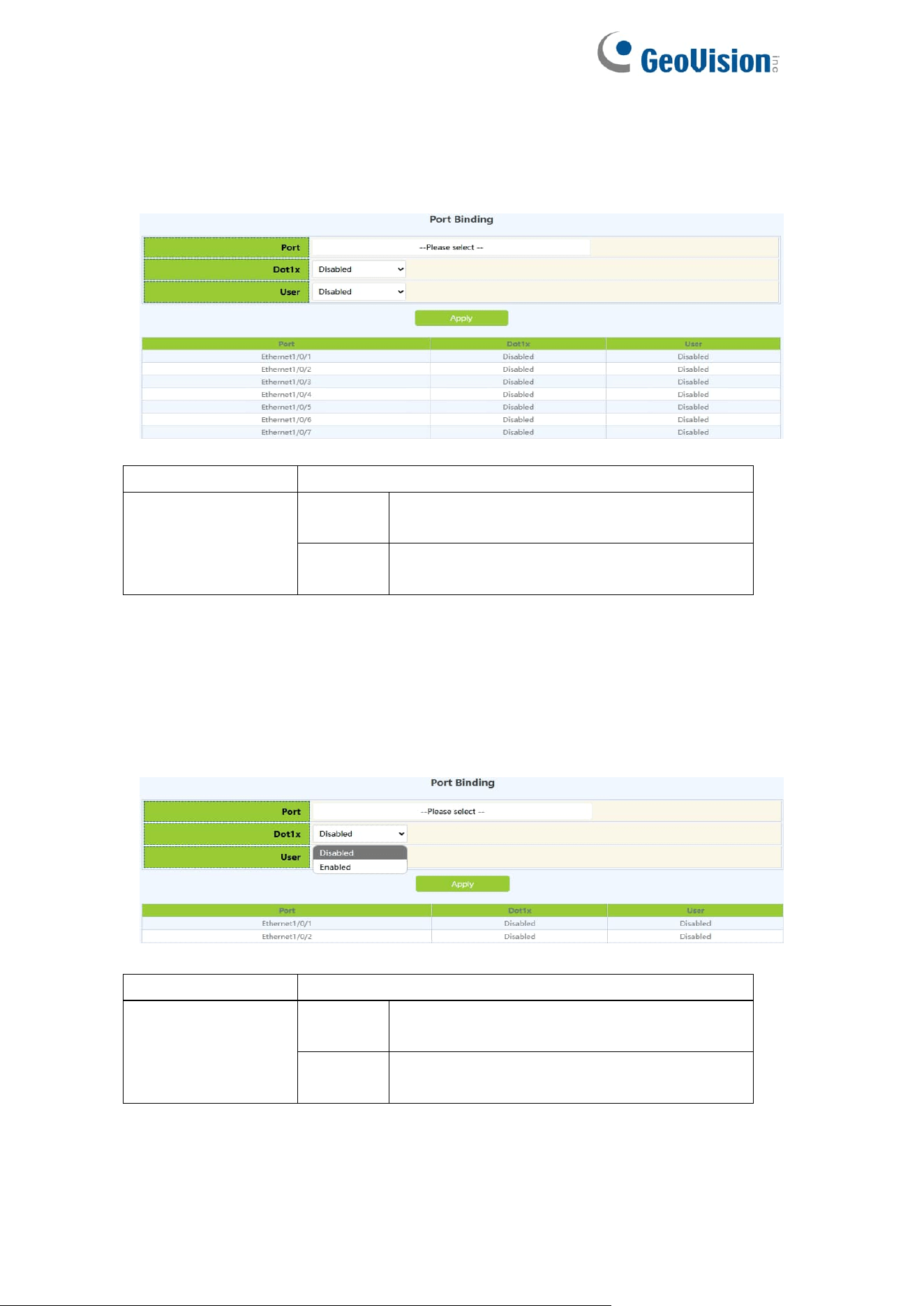
68
5.2.5.Port Binding
DHCP SNOOPING will notify the DOT1X module of the binding information
captured by the user controlled by the DOT1X. DHCP Snooping port binding
dot1x function needs to enable DHCP Snooping binding configuration first.
Port
Port name
DHCP Snooping
binding dot1x
status
Enable
Enable the dot1x status of DHCP
Snooping port binding
Disable
Disable the dot1x binding status of the
DHCP Snooping port
Display the dot1x binding status of each DHCP Snooping port of the switch
When this function is enabled on the port, DHCP SNOOPING will treat the
captured binding information as a trusted user who is allowed to access all
resources. The DHCP Snooping port binding user status function needs to
enable the DHCP Snooping binding configuration first.
Port
Port name
DHCP Snooping
binding user
status
Enable
Enable DHCP Snooping port binding user
status
Disable
Disable DHCP Snooping port binding user
status
Display the status of users bound to each DHCP Snooping port of the
switch
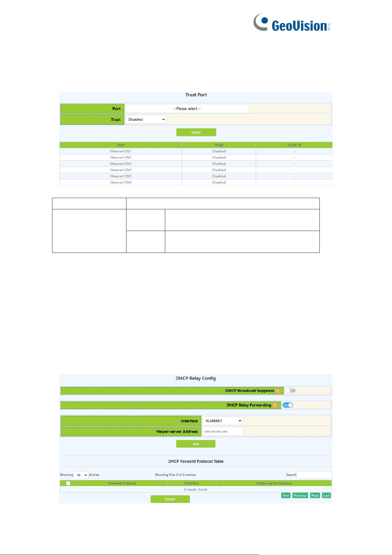
69
5.2.6.Trust Port
When a port changes from an untrusted port to a trusted port, the original
defense action of the port will be automatically deleted; all security history
records will be cleared.
Port
Port name
DHCP Snooping
binding trust
status
Enable
Enable DHCP Snooping port trust
attribute status
Disable
Disable the trust attribute status of the
DHCP Snooping port
Display the trust attribute status of each DHCP Snooping port of the switch
5.3.DHCP Relay Config
5.3.1.DHCP Relay Config
The switch DHCP relay configuration, the user configures the port range, and
the switch sends UDP broadcast messages to the port.
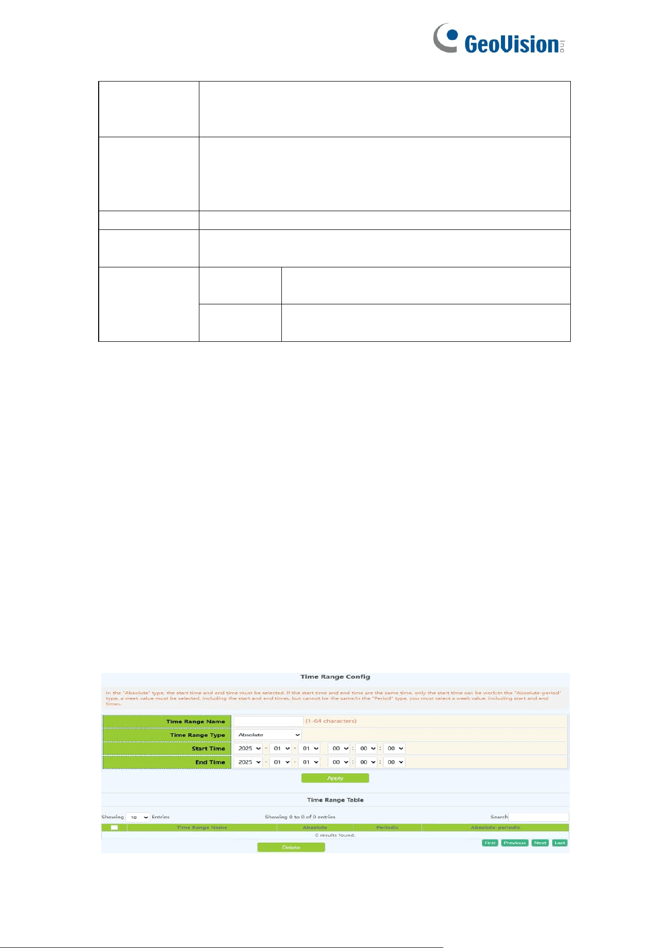
70
DHCP
Broadcast
Suppress
On: Enable DHCP broadcast suppress function
Off: Disable DHCP broadcast suppress function
Default is off
DHCP Relay
Forwarding
On: Sets DHCP relay to forward UPD broadcast packets on
the port
Off: Disable DHCP Relay Forwarding
Defaul is off
Interface
Established Layer 3 interface
Helper-server
Address
IP address of the Layer 3 interface
Operation
Add
Add a Layer 3 interface for DHCP to forward
UDP packets
Delete
Delete the Layer 3 interface through which
DHCP forwards UDP packets
6.ACL Config
6.1.Time Range Config
Time Range configuration module, the user can add or delete the operation of
in this module, which can be applied to various ACL.
In the absolute mode you must input the start-time , end-time is not necesary.
You must input the weeks, start-time and end-time, but need not input the date
including start and end time in the absolute-periodic.
You must input the weeks, start-time and end-time, but need not input the date
including start and end time, and may input multi-week values, separate them
with ",", such as:1-7:monday-sunday;31:daily;96:weekdays;127:weekend.
Input date format: YYYY.MM.DD.Input week format: number (1:Monday etc.), if
input multi-week values, separate them with ",",such as:1,2 identify
monday&tuesday..Input time format: HH:MM:SS.
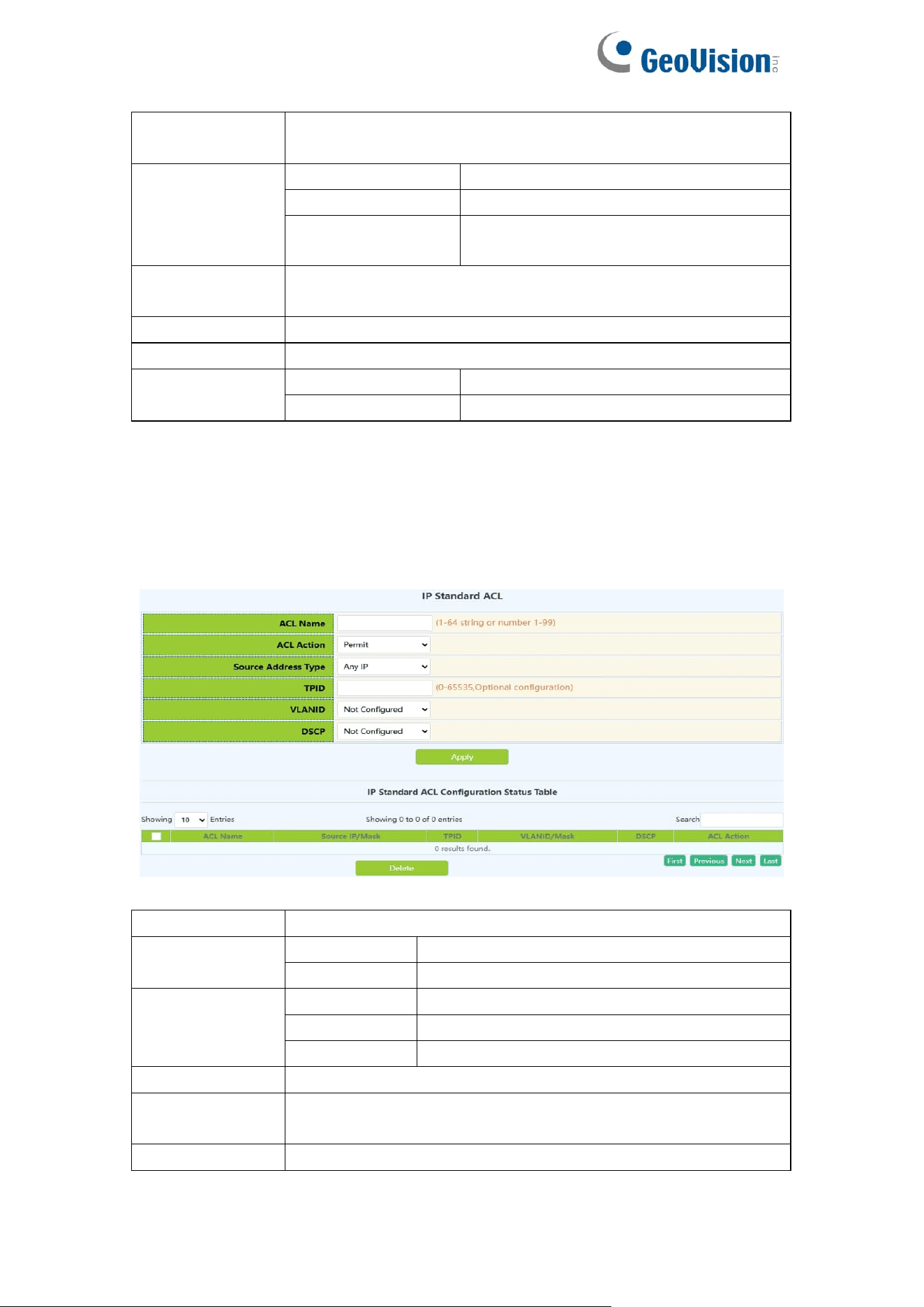
71
Time range
name
Time period names must begin with alphabetic or numeric
characters ,1-64 characters
Time range
type
absolute
Absolutely
absolute-periodic
Absolute-periodic
periodic
periodic
Week
Start or end weeks, "1-7":"monday-sunday";
"31":"daily"; "96":"weekdays"; "127":"weekend"
Time
Start or end time,HH:MM:SS
Date
Start or end date,YYYY.MM.DD,range2001.1.1-2038.12.31
Operation type
Apply
Add operations
Delete
Delete operations
6.2.IP ACL
6.2.1.IP Standard ACL
The digital standard IP access list configuration module, where users can
create or modify parameters for the digital standard IP access list.
List name
Digital Standard IP Access List Number 1-99
Rule
permit
Rule permit
deny
Rule deny
Source
address type
Any IP
Match any IP address
Specified IP
Match IP specified address
Host IP
Match the specified host IP
Source IP
Source IP address, decimal point
Reverse
network mask
Source IP address mask, decimal point
tpid
Label Protocol Identification ,0-65535
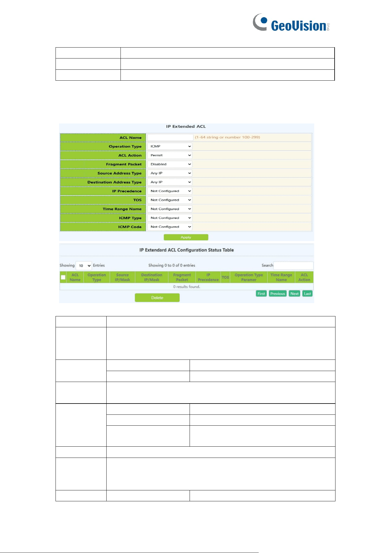
72
VLANID
VLAN ID,1-4094
VLANID mask
VLAN mask,0-4095
dcsp
IP message priority ,0-63
6.2.2.IP Extended ACL
Digital extension IP access list configuration module, where users can create
or modify parameters for digital extension IP access list.
List name
Digital extensions IP access list numbers ,100-199
Operation
type
Extended operation
type:ICMP.IGMP.TCP.UDP.EIGRP.GRE.IGRP.IPINIP.OSPF.IP.or
Specified_protocol
ACL Action
permit
Rule permit
deny
Rule deny
Fragment
packet
Optional whether long messages are transmitted in pieces
Source
address
type
Any IP
Match any IP address
Specified IP
Match IP specified address
Host IP
Match the specified host IP
Source IP
Source IP address, decimal point
Reverse
network
mask
Source IP address mask, decimal point
Destination
Any IP
Match any IP address
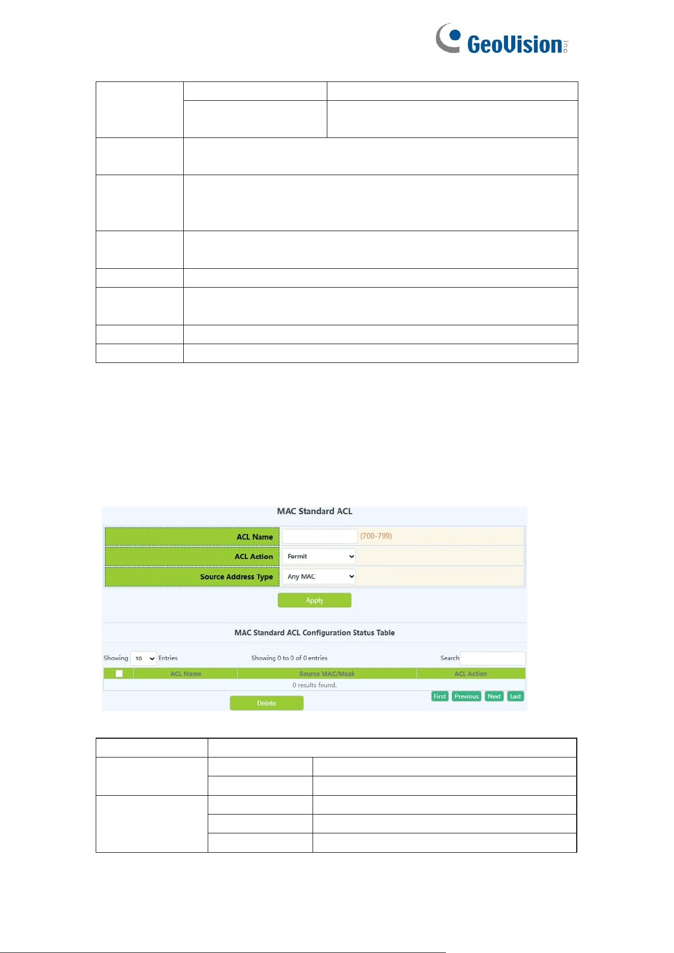
73
address
type
Specified IP
Match IP specified address
Host IP
Match the specified host IP
Destination
IP
Destination IP,decimal points
Reverse
network
mask
Destination IPaddress mask,decimal point
IP
precedence
IP priority ,0-7
TOS
Service type ,0-15
Time range
name
Time period names to be applied must begin with alphabetic or
numeric characters ,1-64 characters
ICMP type
ICMP message type ,0-255
ICMP code
ICMP message code ,0-255
6.3.MAC ACL
6.3.1.MAC Standard ACL
The digital standard MAC access list configuration module, where users can
create or modify parameters for the digital standard MAC access list.
List name
Digital Standard MAC Access List Number 700-799
ACL Action
permit
Rule permit
deny
Rule deny
Source
address type
Any MAC
Match any MAC address
Specified MAC
Match MAC specified address
Host MAC
Match the specified host MAC
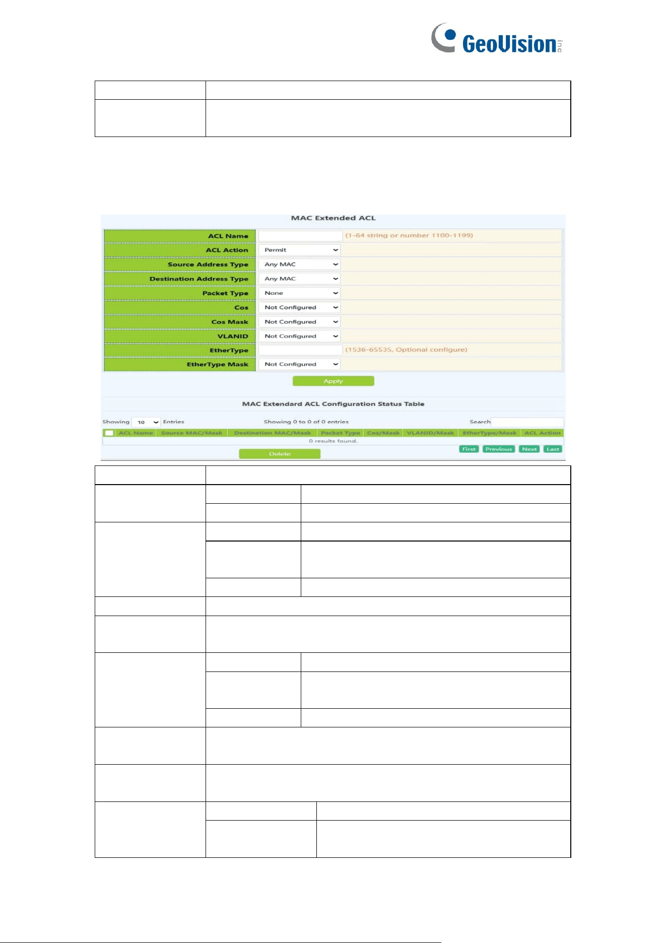
74
Source MAC
Source MAC address
Reverse
network mask
source MAC address inverse mask
6.3.2.MAC Extended ACL
Name extension MAC access list configuration module, where users can
create or modify parameters for named extension MAC access list.
List name
Digital Extension MAC-IP Access List Number ,3100-3199
ACL Action
permit
Rule permit
deny
Rule deny
Source
address type
Any MAC
Match any MAC address
Specified
MAC
Match MAC specified address
Host MAC
Match the specified host MAC
Source MAC
Source MAC address
Reverse
network mask
source MAC address inverse mask
Destination
address type
Any MAC
Match any MAC address
Specified
MAC
Match MAC specified address
Host MAC
Match the specified host MAC
Destination
MAC
Destination MAC address
Reverse
network mask
Destination MAC address inverse mask
Packet type
none
none
tagged-802-3
Format of marked Ethernet 802-3
packets
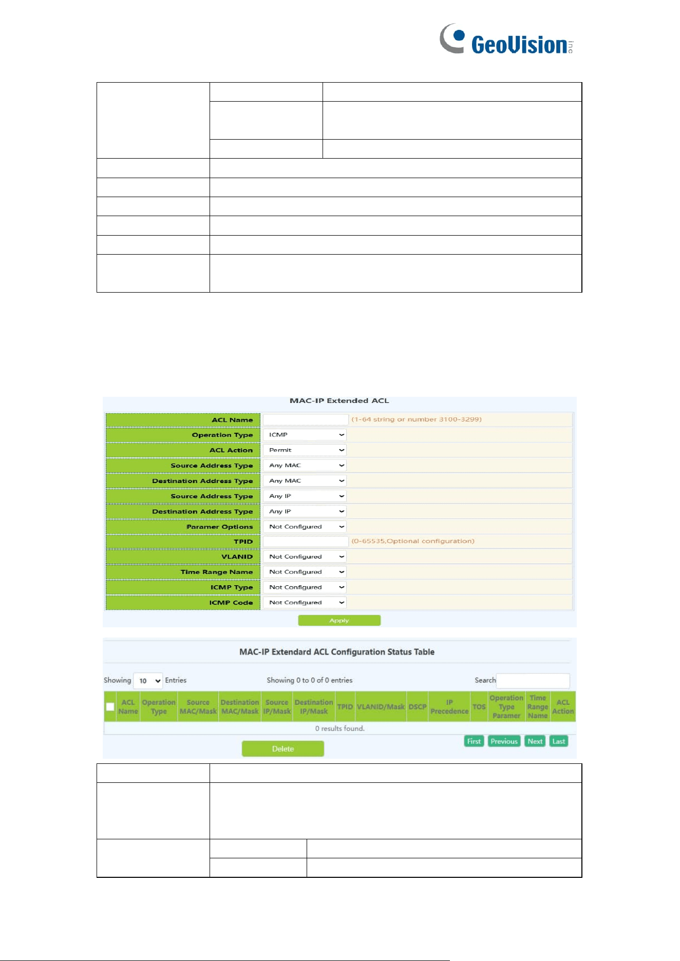
75
tagged-eth2
Format of marked Ethernet II packets
untagged-802-3
Format of unmarked Ethernet 802-3
packets
untagged-eth2
Format of unmarked Ethernet II packets
cos
cos,0-7
cos mask
cos mask,0-7
VLANID
VLAN ID,1-4094
VLANID mask
VLAN mask,0-4095
etherType
Ethernet type field value,1536-65535
etherType
mask
Ethernet type field value mask,0-65535
6.4.MAC-IP Extended ACL
Name extension MAC-IP access list configuration module, where users can
create or modify parameters for named extension MAC-IP access list.
List name
Digital Extension MAC-IP Access List Number ,3100-3199
Operation type
Extension operation type :
ICMP.IGMP.TCP.UDP.EIGRP.GRE.IGRP.IPINIP.OSPF.IP.or
Specified_protocol
ACL Action
permit
Rule permit
deny
Rule deny

76
Source
address type
Any MAC
Match any MAC address
Specified
MAC
Match MAC specified address
Host MAC
Match the specified host MAC
Source MAC
Source MAC address
Reverse
network mask
source MAC address inverse mask
Destination
address type
Any MAC
Match any MAC address
Specified
MAC
Match MAC specified address
Host MAC
Match the specified host MAC
Destination
MAC
Destination MAC address
Reverse
network mask
Destination MAC address inverse mask
Source
address type
Any IP
Match any IP address
Specified IP
Match IP specified address
Host IP
Match the specified host IP
Source IP
Source IP address, decimal point
Reverse
network mask
Source IP address mask, decimal point
Destination
address type
Any IP
Match any IP address
Specified IP
Match IP specified address
Host IP
Match the specified host IP
Destination IP
Destination IP,decimal points
Reverse
network mask
Destination IPaddress mask,decimal point
tpid
Label Protocol Identification ,0-65535
VLANID
VLAN ID,1-4094
VLANID mask
VLAN mask,0-4095
dcsp
IP message priority 0-63
IP precedence
IP priority ,0-7
TOS
Service type ,0-15
Time range
name
Time period names to be applied must begin with
alphabetic or numeric characters ,1-64 characters
ICMP type
ICMP message type ,0-255
ICMP code
ICMP message code ,0-255
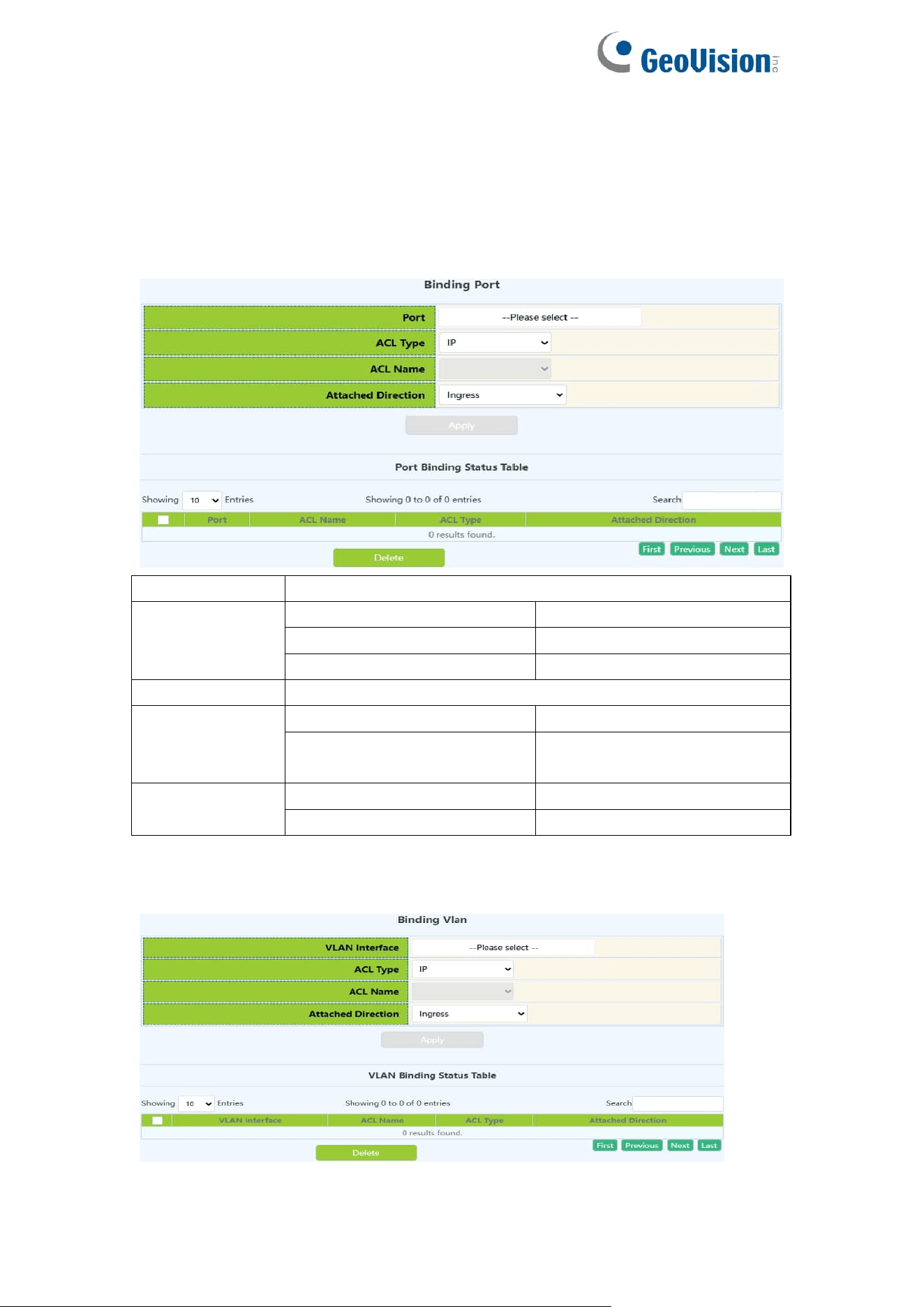
77
6.5.ACL Binding
6.5.1.Binding Port
ACL port binding module, the user can bind and delete the access list of the
specified port.
Port
Designated port number
ACL type
IP
IP type
MAC
MAC type
MAC-IP
MAC-IP type
List name
Specify access list name ,1-64 characters
ACL Attached
Direction
in
Application ACL only
in and traffic-statistics
Application ACL and flow
monitoring
Operation type
Apply
Add operations
Delete
Delete operations
6.5.2.Binding Vlan
ACL vlan binding module, where users can bind and delete access lists to
specified VLAN.
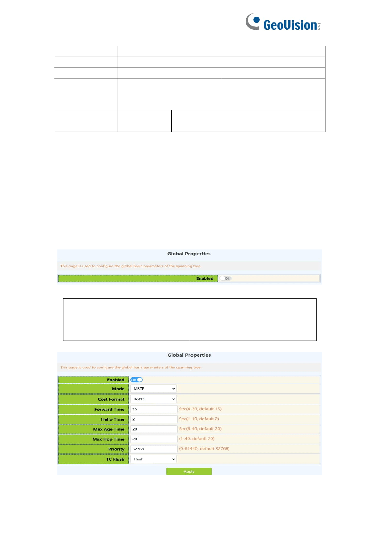
78
VLAN interface
Specifies the VLAN number to operate on
ACL type
Specifies the type of ACL to bind: IP.MAC.MAC-IP
List name
Specify access list name ,1-64 characters
ACL Attached
Direction
in
Application ACL only
in and traffic-statistics
Application ACL and flow
monitoring
Operation type
Add
Add operations
Remove
Delete operations
7.Ring Network
7.1.Spanning-tree
7.1.1.Global Properties
This page uses the build tree function with global enable.
To display the “Global Properties” page,click Ring Network -> Spanning-tree
-> Global Properties,click "Apply" to configure.
entry
describe
Operation
On:enable spanning tree function
Off:disables spanning tree
functionality

79
Mode
Generating tree protocol type:
Mstp.Stp.Rstp
Cost Format
Path cost format:Dot1t.Dot1d
Forward Time
Size range :4-30, in seconds,the
following conditions shall be met:
2 * (Bridge_Forward_Delay - 1.0
seconds) >= Bridge_Max_Age
Bridge_Max_Age >= 2 *
(Bridge_Hello_Time + 1.0 seconds)
Hello Time
Size range :1-10, in seconds,the
following conditions shall be met:
2 * (Bridge_Forward_Delay - 1.0
seconds) >= Bridge_Max_Age
Bridge_Max_Age >= 2 *
(Bridge_Hello_Time + 1.0 seconds)
Max Age Time
Size range :6-40, in seconds,the
following conditions shall be met:
2 * (Bridge_Forward_Delay - 1.0
seconds) >= Bridge_Max_Age
Bridge_Max_Age >= 2 *
(Bridge_Hello_Time + 1.0 seconds)
Max Hop Time
Numerical range :1-40
Priority
Numerical range :0-61440, and an
integer multiple of 4096
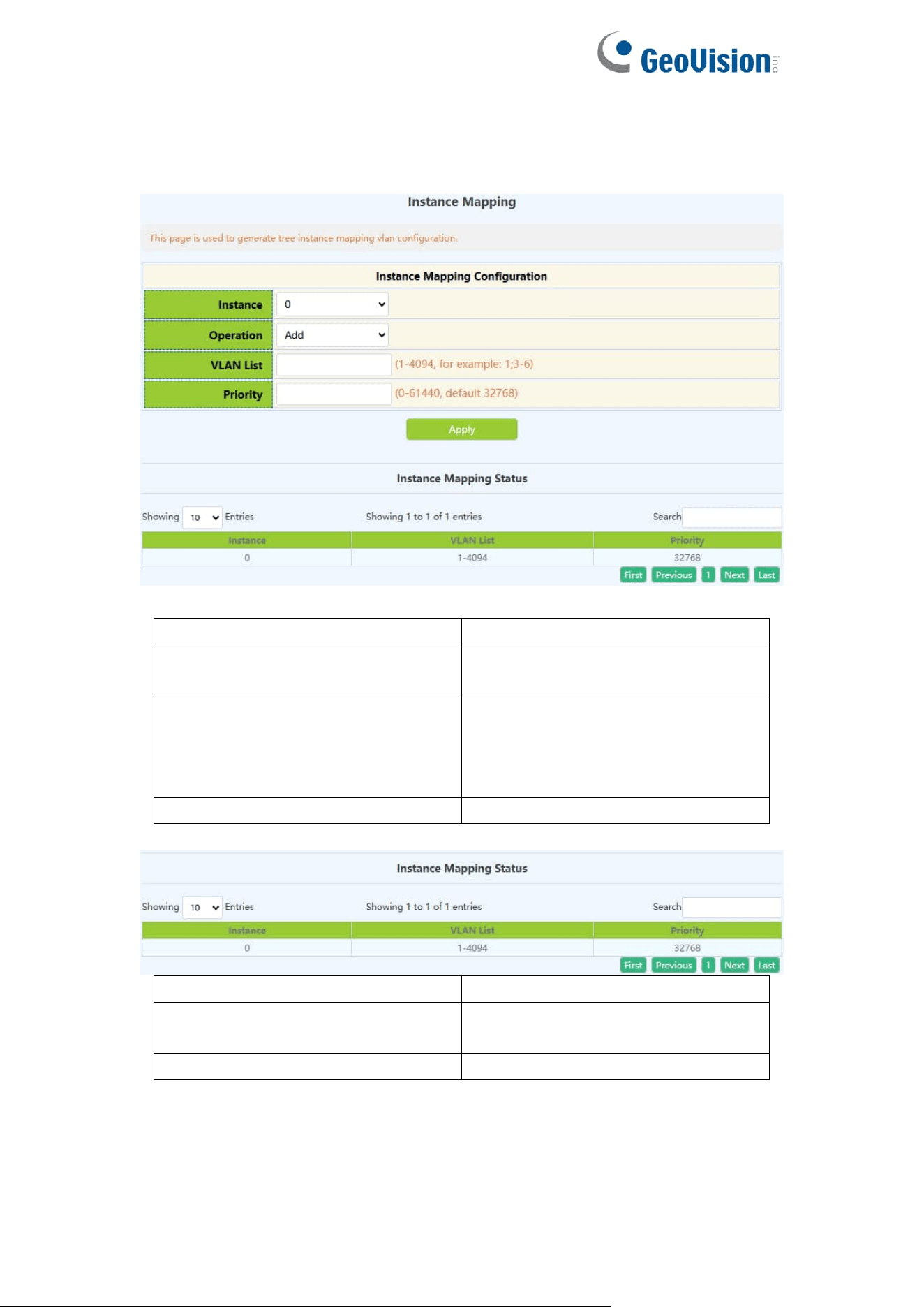
80
7.1.2.Instance Mapping
This page can be used to configure the mapping relationship between the
spanning tree instance and the VLAN.
entry
describe
Instance name
Generating tree instance ID,
range 0-64
Operation
Add:Add the above configuration
information
Delete:Delete the above
configuration information
VLAN name
VLAN ID,range :1-4094
entry
describe
Instance name
Generating tree instance ID, size
range 0-64
VLAN name
VLAN ID,range :1-4094
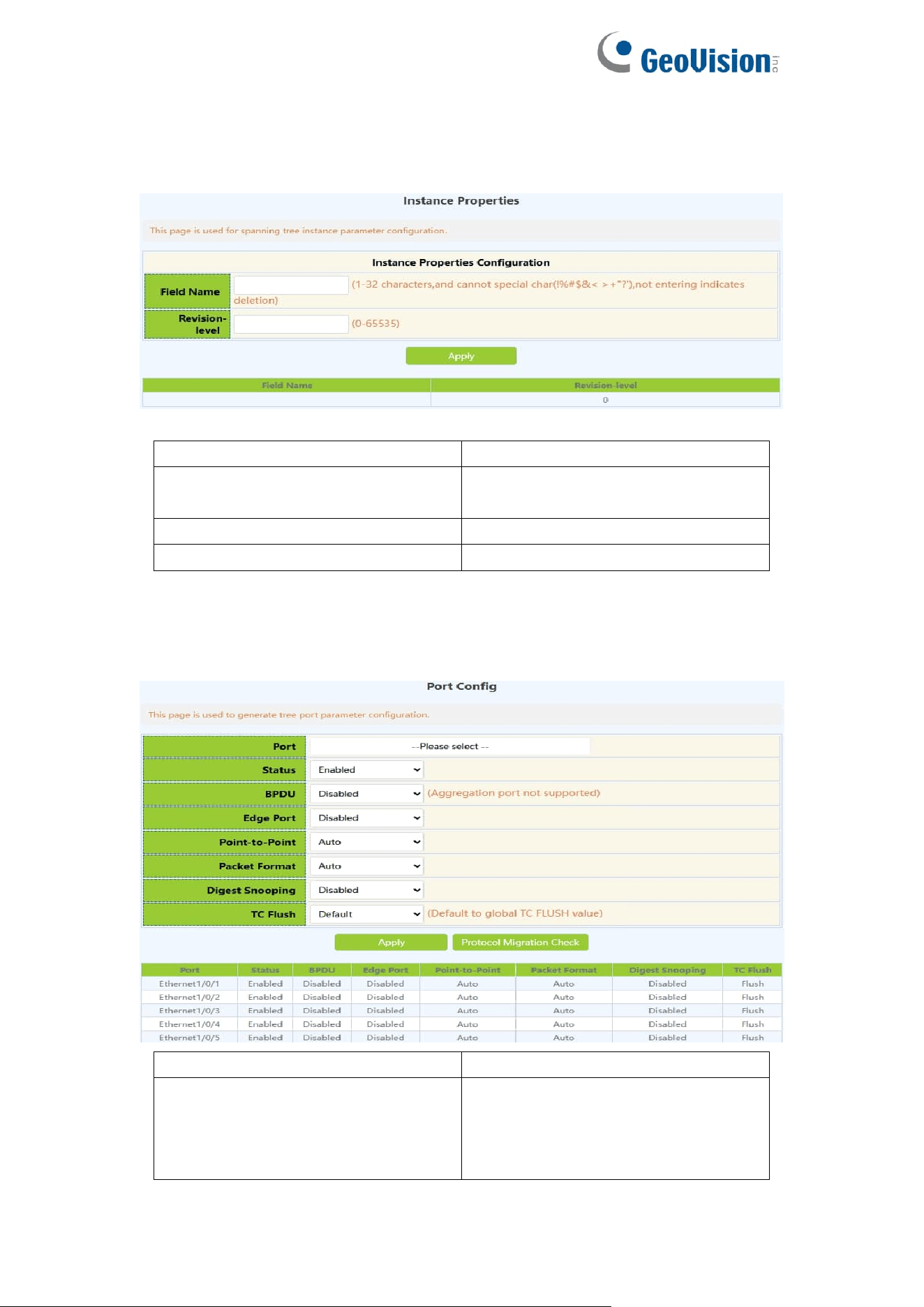
81
7.1.3.Instance Properties
This page can be used to configure MSTP domain name and MSTP revision
level.
entry
describe
Field name
MSTP domain name,the length is
1-32 characters
Revision-level
Range :0-65535
Operation
Apply:Use the above configuration
7.1.4.Port Config
This page can be used to configure enable or disable the tree generation
function under the port.
Port
Ethernet port name
Status
Enable:Port enable spanning tree
function
Disable:Port disables spanning
tree functionality
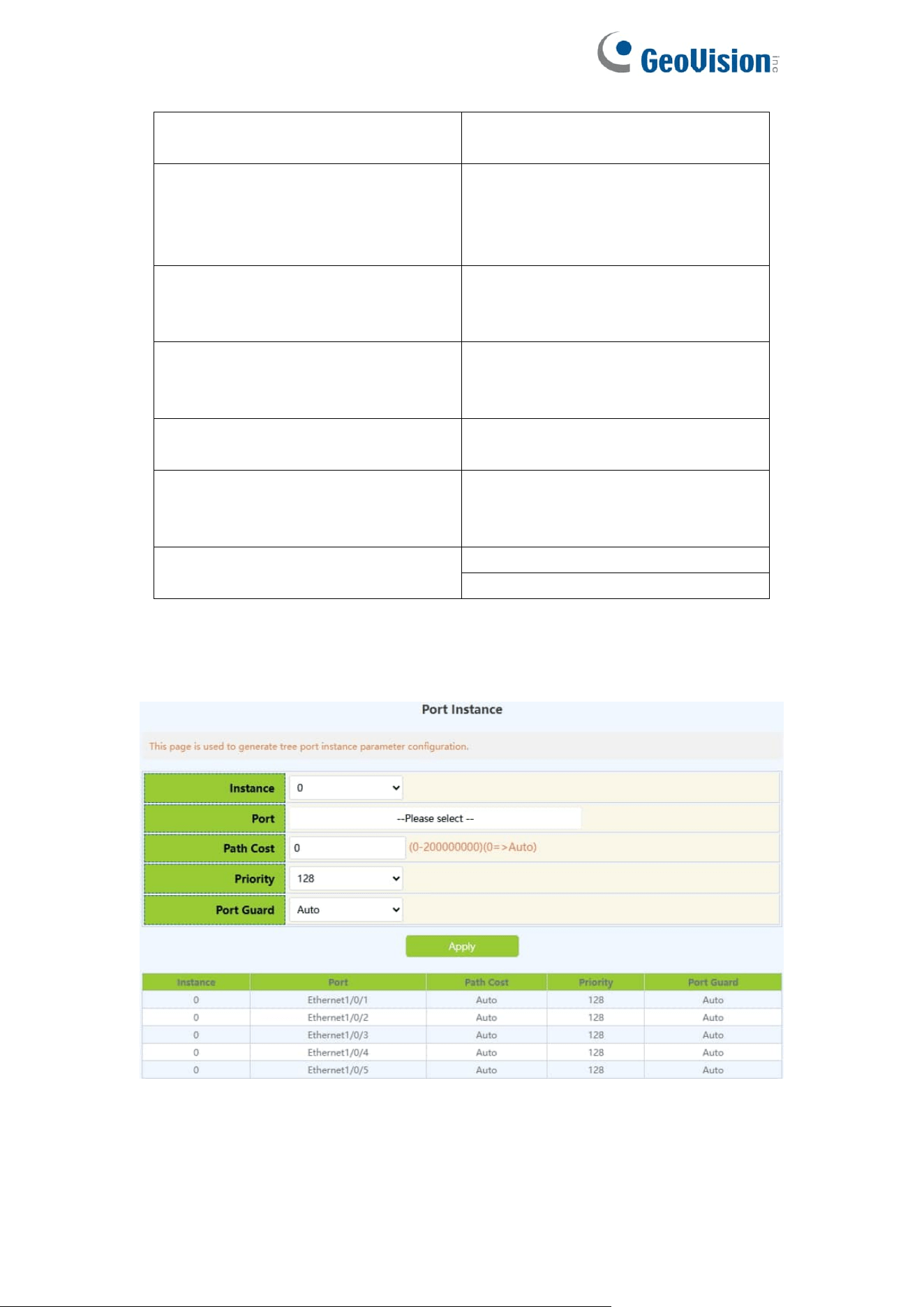
82
BPDU
Disabled;
VLAN:1-4094
Edge Port
Disabled;
Enabled;
BPDU Filter;
BPDU Guard;
Point-to-Point
Auto;
Disabled;
Enabled;
Packet Format
Auto;
Privacy;
Standard;
Digest Snooping
Disabled;
Enabled;
TC Flush
no Flush;
Flush;
Limit
Operation
Apply
Protocol Migration Check
7.1.5.Port Instance
This page can be used for configuration of instance port priority.
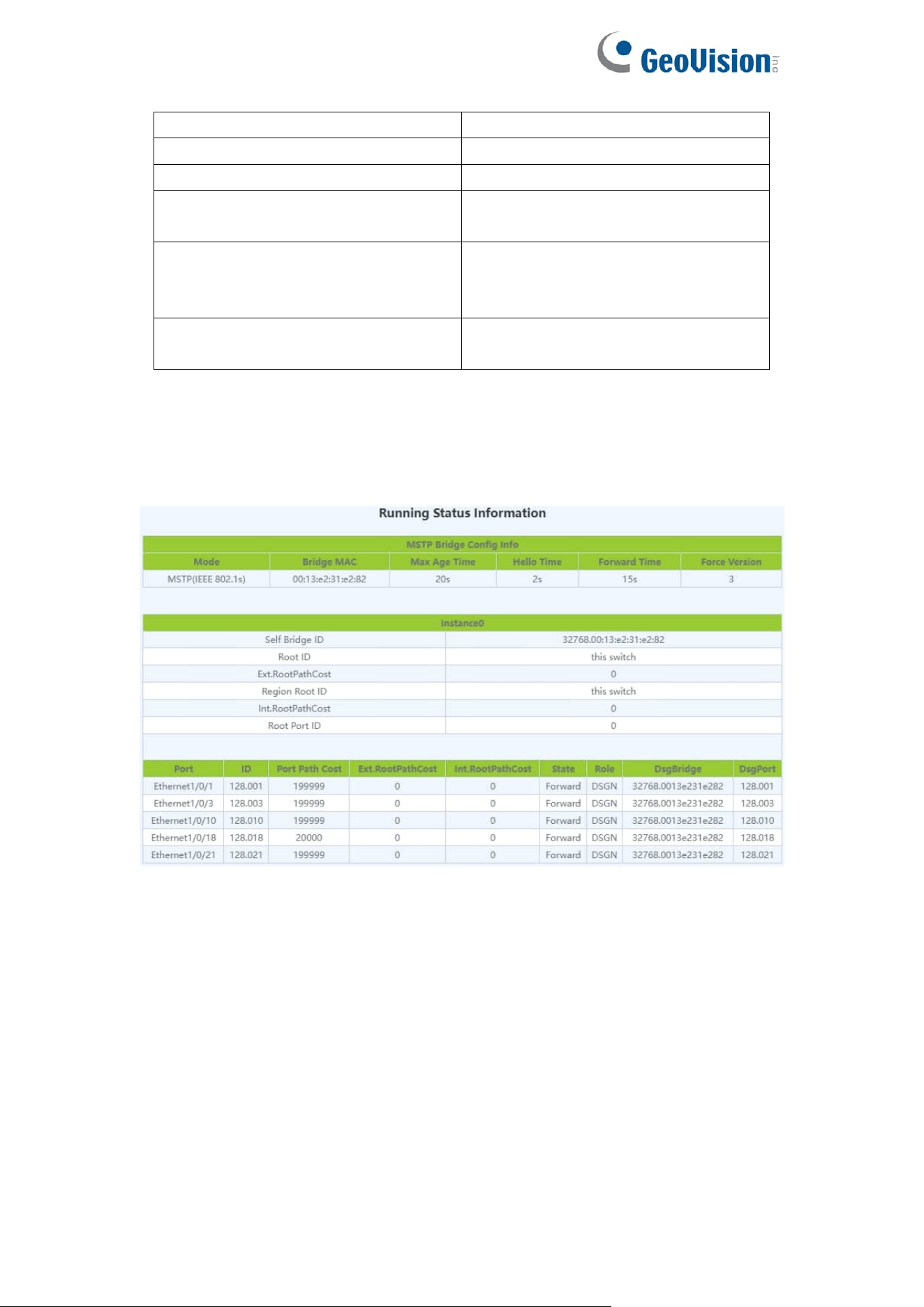
83
Instance name
Generate tree instance name
Port
Ethernet port name
Cost
Size range :0-200000000
Priority
The size range is :0-240, multiple
of 16
Priority
Auto;
Root Guard;
Loop Guard;
Operation
Configuration:Apply the above
configuration
7.1.6.Status
This page can be used to view information for the spanning-tree status.
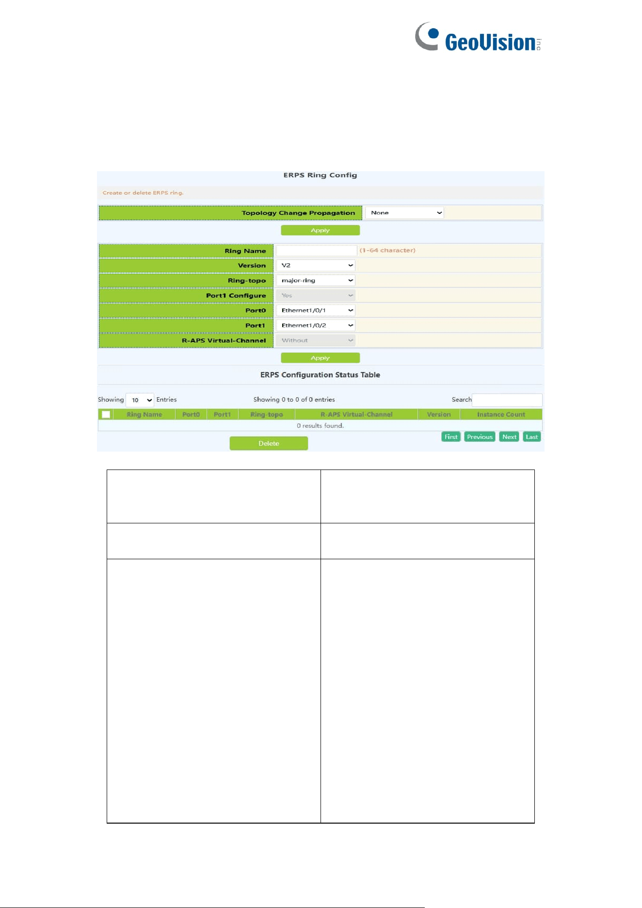
84
7.2.ERPS
7.2.1.ERPS Ring Config
This page can be used for configuration of ERPS Ring.
Topology Change Propagation
None;
ERPS;
STP;
Ring Name
The ERPS ring name created,1-64
character
Version
If configured ERPS ring to support
v1, this ring will not support
multi-instance. ERPS ring instance
does not support the management
commands of MS, FS.
If configured ERPS ring to support
v2, the instance of this ring will deal
with the ERPS packets according
to the v1 format. Package the
R-APS packets and resolve the
fields according to v1 format. The
fields defined by v2 will not be
dealt.
V1: Means to support v1 which is
released in 2008-06 and the

85
amendment (2009-04)
V2: Means to support v2 which is
released in 2010-03 and the
amendment (2010-06)
Ring-topo
major-ring: Configure the ERPS
ring as the major ring
open-ring: Configure the ERPS ring
as the open ring
Port1 Configure
No: Port1 is not allowed to be
configured.
Yes: Port1 is allowed to be
configured.
Port0
Select port as Port 0 for ERPS
Port1
Select port as Port 1 for ERPS
R-APS Virtual-Channel
Configure if there is the R-APS
virtual channel in ERPS ring
according to the configuration.
Inputting: Success or error. If there
is not R-APS virtual channel on the
ERPS ring, the R-APS channel of
all the instances of ERPS ring will
be unblocked forever and it only
blocks the data channel; otherwise,
the R-APS channel and the data
channel will be blocked at the same
time.
Without: The R-APS virtual channel
is not existed in this ERPS ring.
With: The R-APS virtual channel is
existed in this ERPS ring.
Operation
Apply
Delete
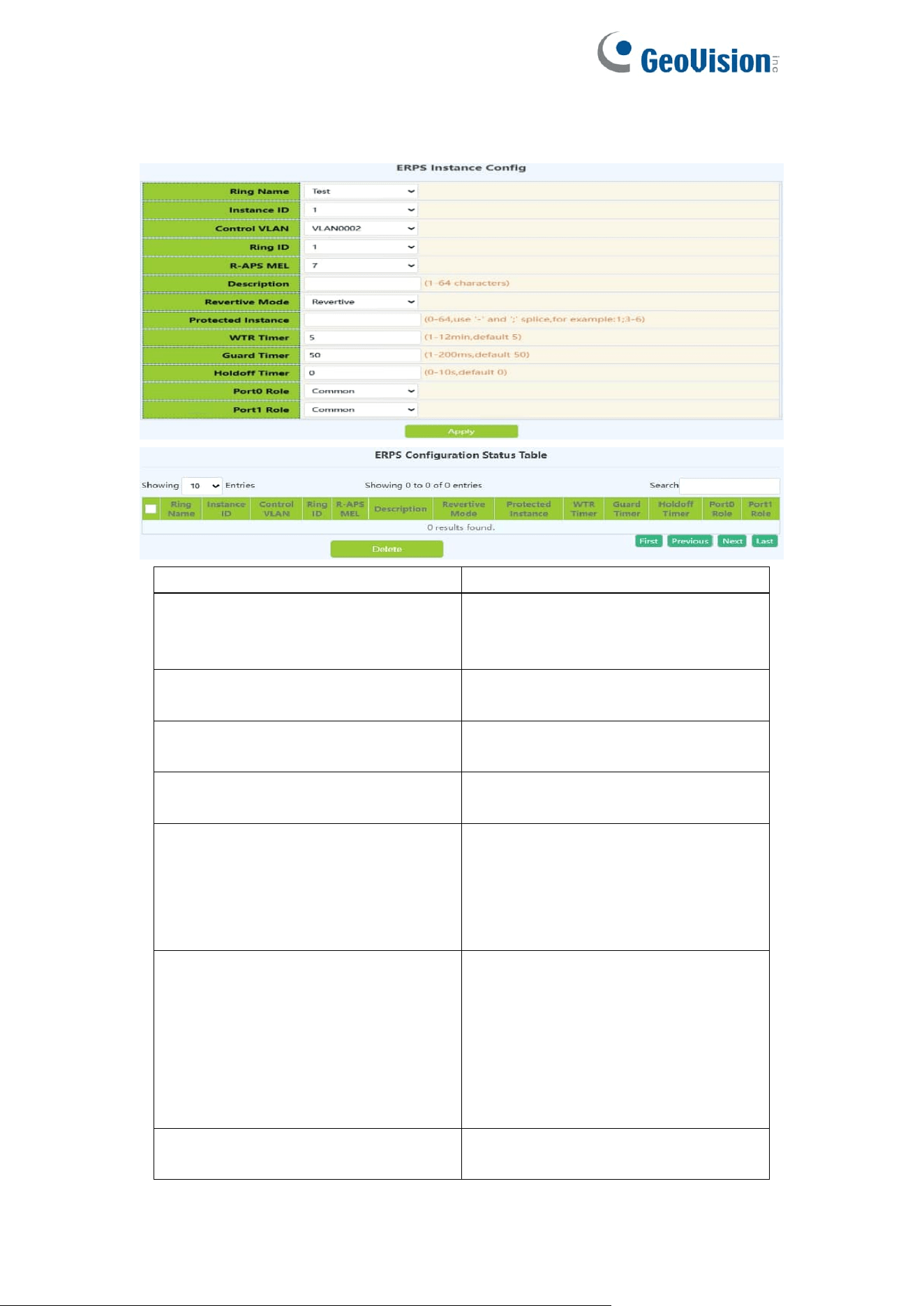
86
7.2.2.ERPS Instance Config
This page can be used for configuration of ERPS Instance.
Ring Name
Select the ERPS ring you created
Instance ID
Create the ERPS ring instance ID,
id of ERPS ring, the range is 1 to
16
Control Vlan
vlan id of R-APS packets, range is
from 2 to 4094
Ring ID
ERPS ring id and the range is 1 to
64
R-APS MEL
The level value of APS packets,
range is from 1 to 7
Description
ERPS instance name, the
maximum string is 64, and it is
made up with letters, numbers and
underlines; the first and last
characters cannot be underlines.
Revertive Mode
Configure the ERPS ring instance
as non-revertive. If this ERPS ring
supports v1, then cannot be
configured. Only configured on the
RPL owner node of the sub ring.
Non-Reviertive;
Reviertive;
Protect ID
The MSTP instance list protected
by ERPS ring instance

87
WTR Timer
WTR timer is used to avoid the
frequent protection switching of
RPL owner node because of the
periodic (intermittent) default.The
interval is 1min and the range is
from 1 to 12min, default is 5min.
Guard Timer
The guard timer is used for the
Ethernet node to avoid the error
handling and the close loop
according to the outdated R-APS
packets. The interval is 10ms and
the range is 10ms to 2s, default is
500ms.
Holdoff Timer
The interval is 1s and the range is 0
to 10s, default is 0s.
Port0 Role
Common is default config, it is the
ordinary transmission node type.
• Owner
• Neighbour
• Common
Port1 Role
Operation
Apply
Delete

88
7.2.3.View ERPS Statistics
This page can be used for configuration of ERPS Statistics.
Ring Name
The ERPS ring name whe you created
Instance ID
The ERPS ring instance ID when you create
Intance Port
The ERPS ring member ports
Port Role
ERPS ring node roles: RPL Owner, RPL neighbor,
Common
Port States
Blocked: port is in block status
forwarding: port is in forwarding status
Signal Status
ERPS ring port fault status:
Non-failed: no fault
Failed: fault happened
Last NodeID
The node ID information is the last bit of the MAC
address
Last Bpr
The block link information carried by the receiving
last R-APS saved by ERPS ring port, it is port0 or
port1 which was blocked.
rbTX
RB transport statistics
rbRX
RB receive statistics
nrTX
NR transport statistics
nrRX
NR receive statistics
fsTX
FS transport statistics
fsRX
FS receive statistics
msTX
MS transport statistics
msRX
MS receive statistics
sfTX
SF transport statistics
sfRX
SF receive statistics
eventTX
Event transport statistics
eventRX
Event receive statistics
totalTX
Total transport statistics
totalRX
Total receive statistics
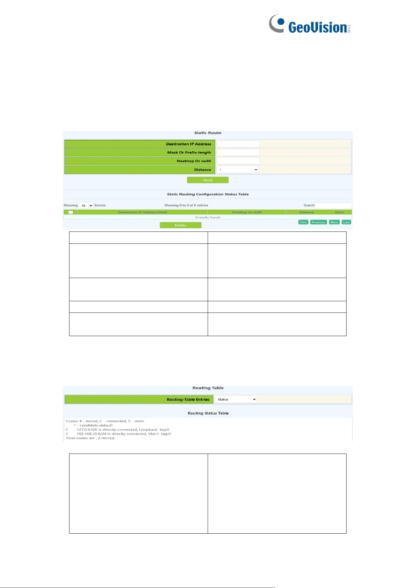
89
8.Route Config
8.1.Static Route
This page can be used for the basic configuration of static routing.
Destination IP address
IP address, format :10.10.11.11
Network mask or prefix-length
Subnet mask in the following
format :255.255.255.0; or mask
length
Nexthop or Interface null0
IP address, format :10.10.11.11. or
null0
Distance
Range :1-255
Operation type
Apply:Add the above settings
Delete:Delete the above
8.2.Routing Table
This page can be view for the basic status of routing table.
Routing-Table Entries
Status;
Database;
Connect Route;
Static Route;
Statistics;
Kernel Route;
FIB;
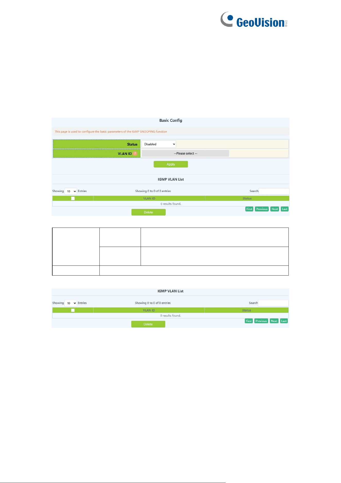
90
9.Multicast Manage
9.1.IGMP Snooping Config
9.1.1.Basic Config
Switch IGMP Snooping global switch, snooping IGMP messages
Switch
on-off IGMP
Snooping
Enable
Turn on the global switch of IGMP Snooping
on the switch
Disable
Turn off the global switch of IGMP Snooping
on the switch
VLAN ID
Created VLAN ID
Display the current existing VLAN interface and the running status of IGMP
Snooping under the VLAN interface
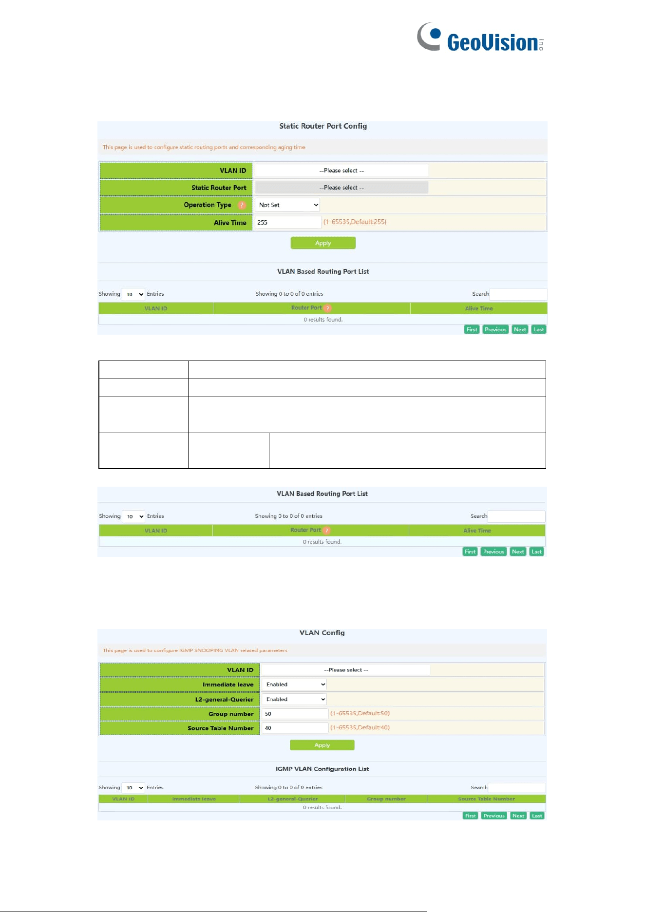
91
9.1.2.Static Router Port
IGMP Snooping mrouter port parameter configuration.
VLAN ID
Created VLAN ID
Mrouter port
Port name
Mrouter port
alive time
Time to live of the port, range: 1-65535
Operation
type
Apply
Add the mrouter port parameter configuration
checked under the selected VLAN
Display current configuration information
9.1.3.VLAN Config
Configure IGMP Snooping based on VLAN interface.
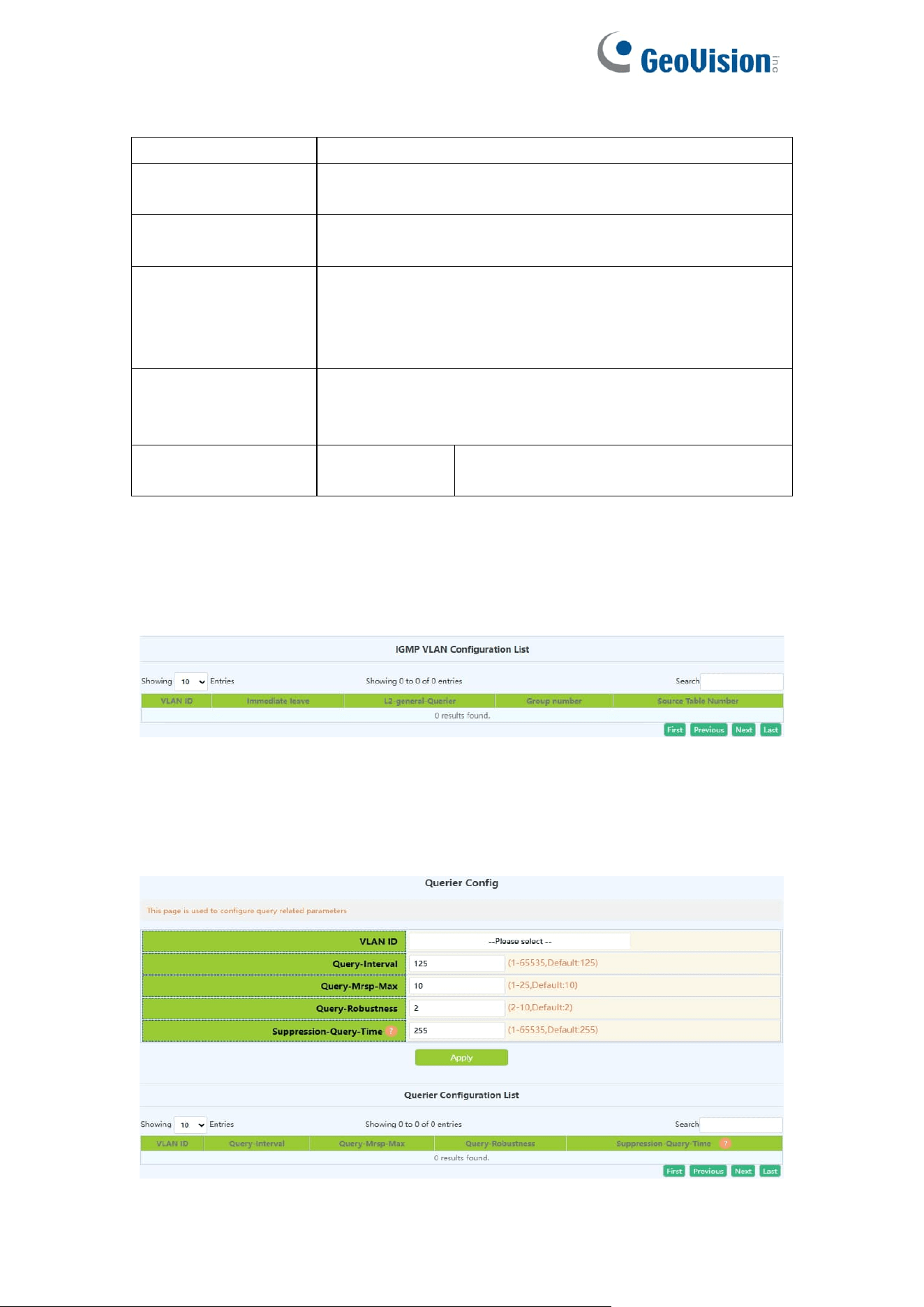
92
VLAN ID
Created VLAN ID
Immediate leave
configuration
IGMP fast leave function in VLAN
L2-general-querier
configuration
Used to send regular queries regularly to help switches
in this network segment learn the mrouter port
Group number
The upper limit of the total number of groups. When the
number of joined groups reaches the limit, the newly
joined groups will be rejected to prevent hostile attacks.
The default is 50, and the range: 1-65535.
Source table
number
The maximum number of source entries in each group,
including include sources and exclude sources. The
default is 40, and the range: 1-65535.
Operation
Configuration
Configure the checked parameters into
the selected VLAN
Note: Whether it is to configure parameters or restore the default state, it is
required to check the box at the back to take effect. The group number and the
number of source table entries are unified functions, so the two function
parameters will take effect together (when one parameter is set, the other will
be set to the default value).
Display the configuration parameters of the existing VLAN
9.1.4.Querier Config
IGMP Snooping query parameter configuration.
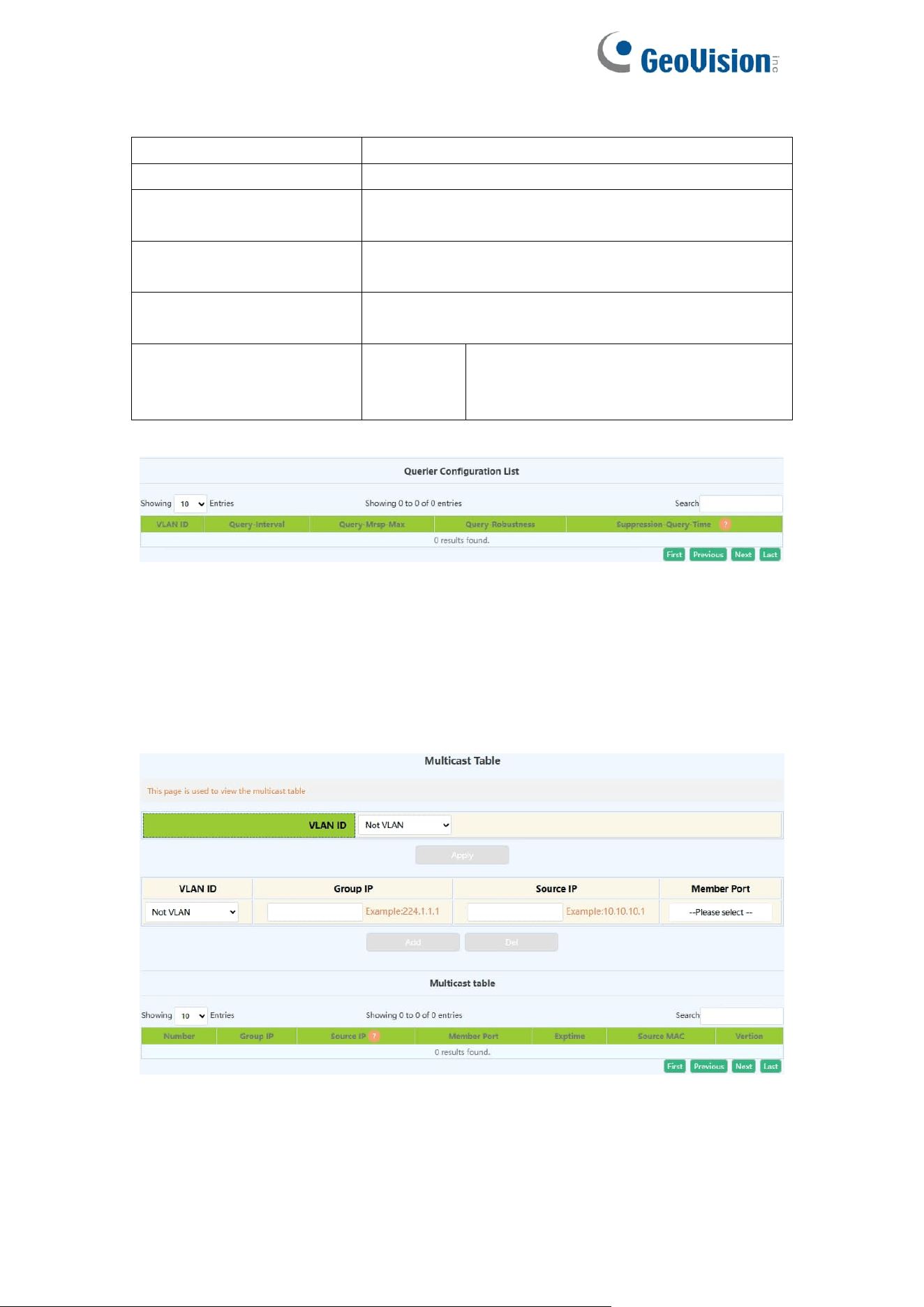
93
VLAN ID
Created VLAN ID
Query-Interval
IGMP Snooping query interval, range: 1-65535
Query-mrsp
configuration
Maximum response time for group query
Query-robustness
configuration
IGMP Snooping robustness, range: 2-10
Suppression-query-time
configuration
Prohibited query time, range: 1-65535
Operation type
Apply
Add the mrouter port parameter
configuration checked under the
selected VLAN
Display current configuration information
9.1.5.Multicast Table
The page displayed multicast table information.
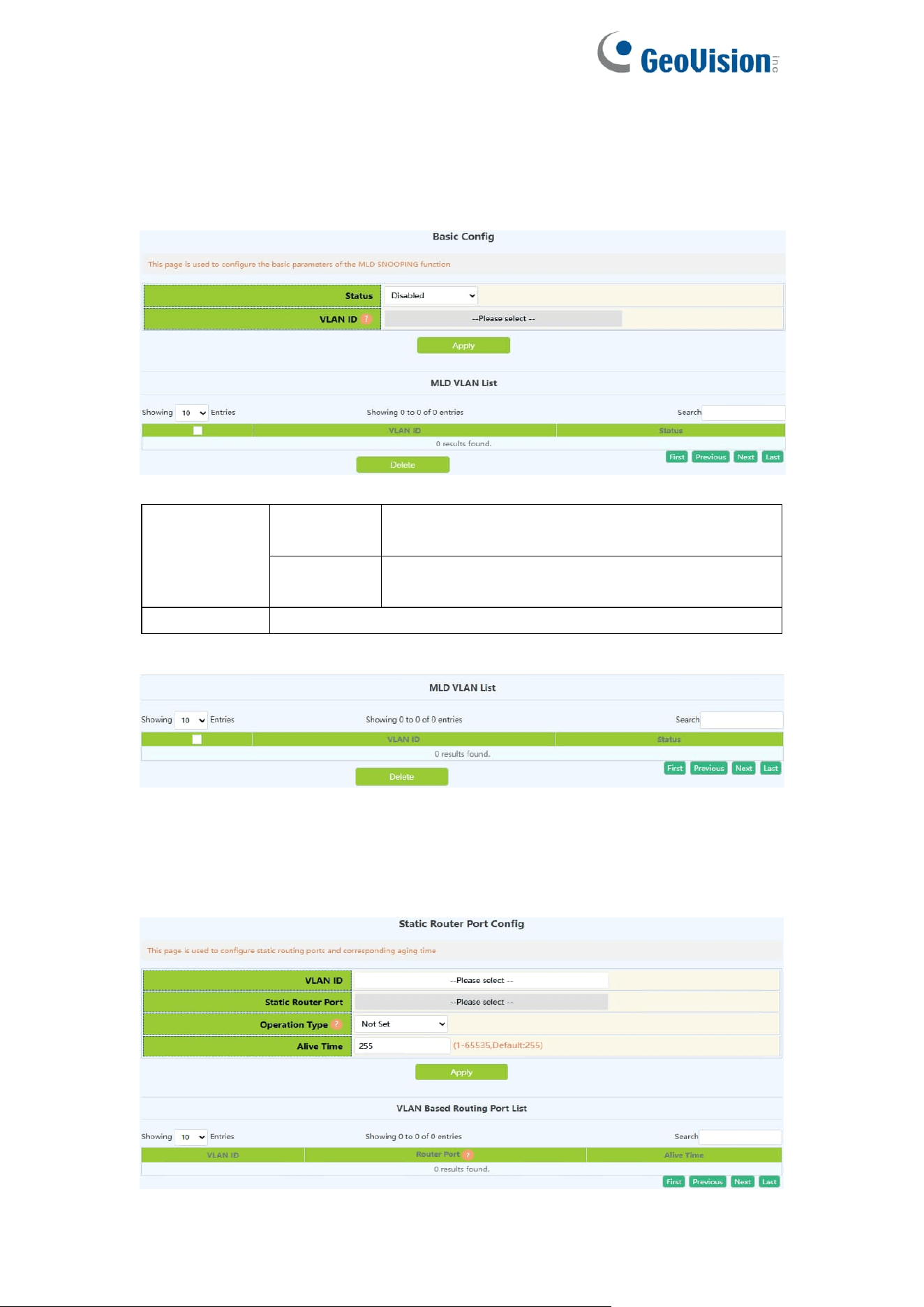
94
9.2.MLD Snooping Config
9.2.1.Basic Config
Switch MLD Snooping global switch, MLD snooping messages
Switch
on-off IGMP
Snooping
Enable
Turn on the global switch of IGMP Snooping
on the switch
Disable
Turn off the global switch of IGMP Snooping
on the switch
VLAN ID
Created VLAN ID
Display the current existing VLAN interface and the running status of IGMP
Snooping under the VLAN interface
9.2.2.Static Router Port
MLD Snooping mrouter port parameter configuration.
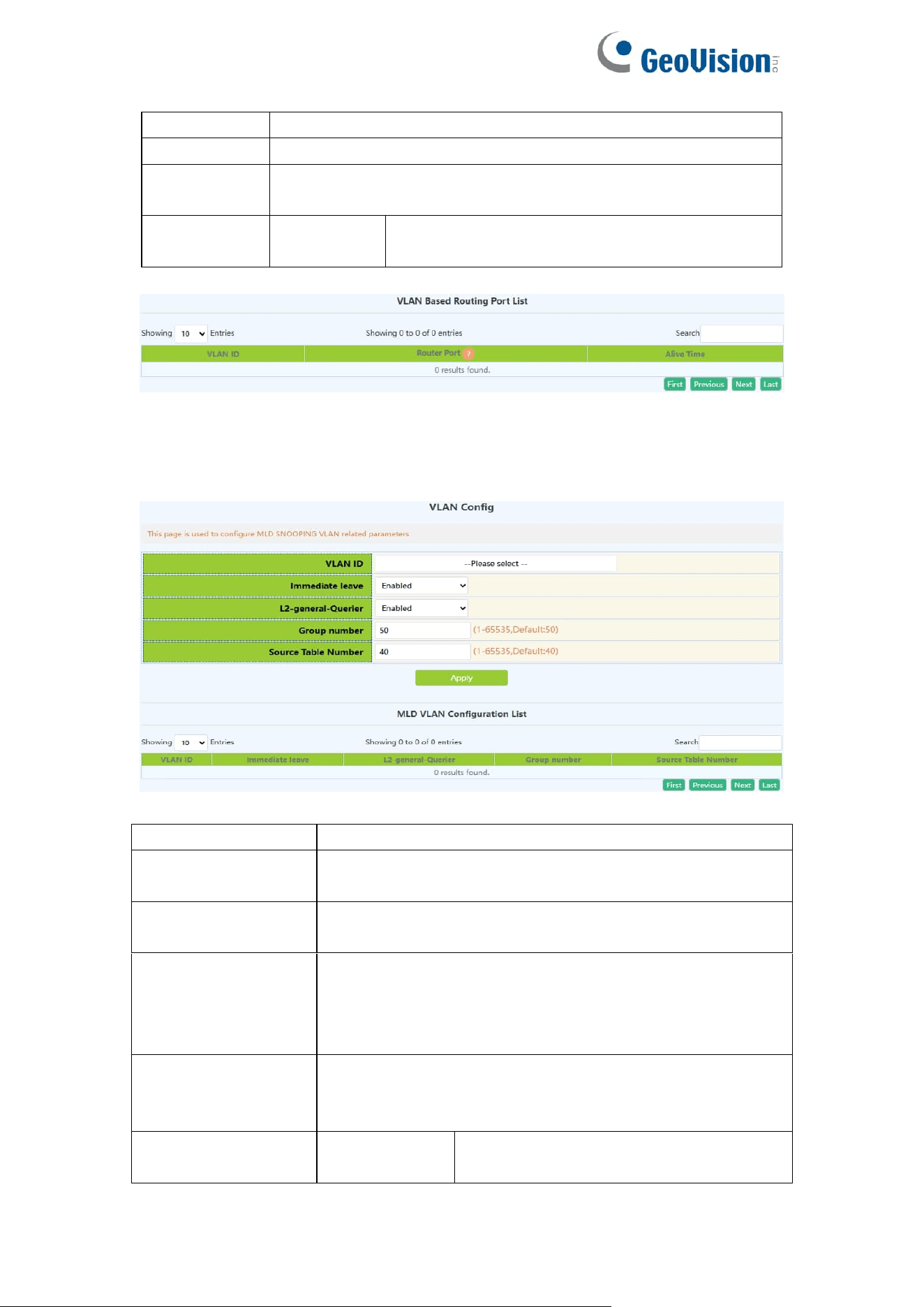
95
VLAN ID
Created VLAN ID
Mrouter port
Port name
Mrouter port
alive time
Time to live of the port, range: 1-65535
Operation
type
Apply
Add the mrouter port parameter configuration
checked under the selected VLAN
Display current configuration information
9.2.3.VLAN Config
Configure MLD Snooping based on VLAN interface.
VLAN ID
Created VLAN ID
Immediate leave
configuration
MLD fast leave function in VLAN
L2-general-querier
configuration
Used to send regular queries regularly to help switches
in this network segment learn the mrouter port
Group number
The upper limit of the total number of groups. When the
number of joined groups reaches the limit, the newly
joined groups will be rejected to prevent hostile attacks.
The default is 50, and the range: 1-65535.
Source table
number
The maximum number of source entries in each group,
including include sources and exclude sources. The
default is 40, and the range: 1-65535.
Operation
Configuration
Configure the checked parameters into
the selected VLAN
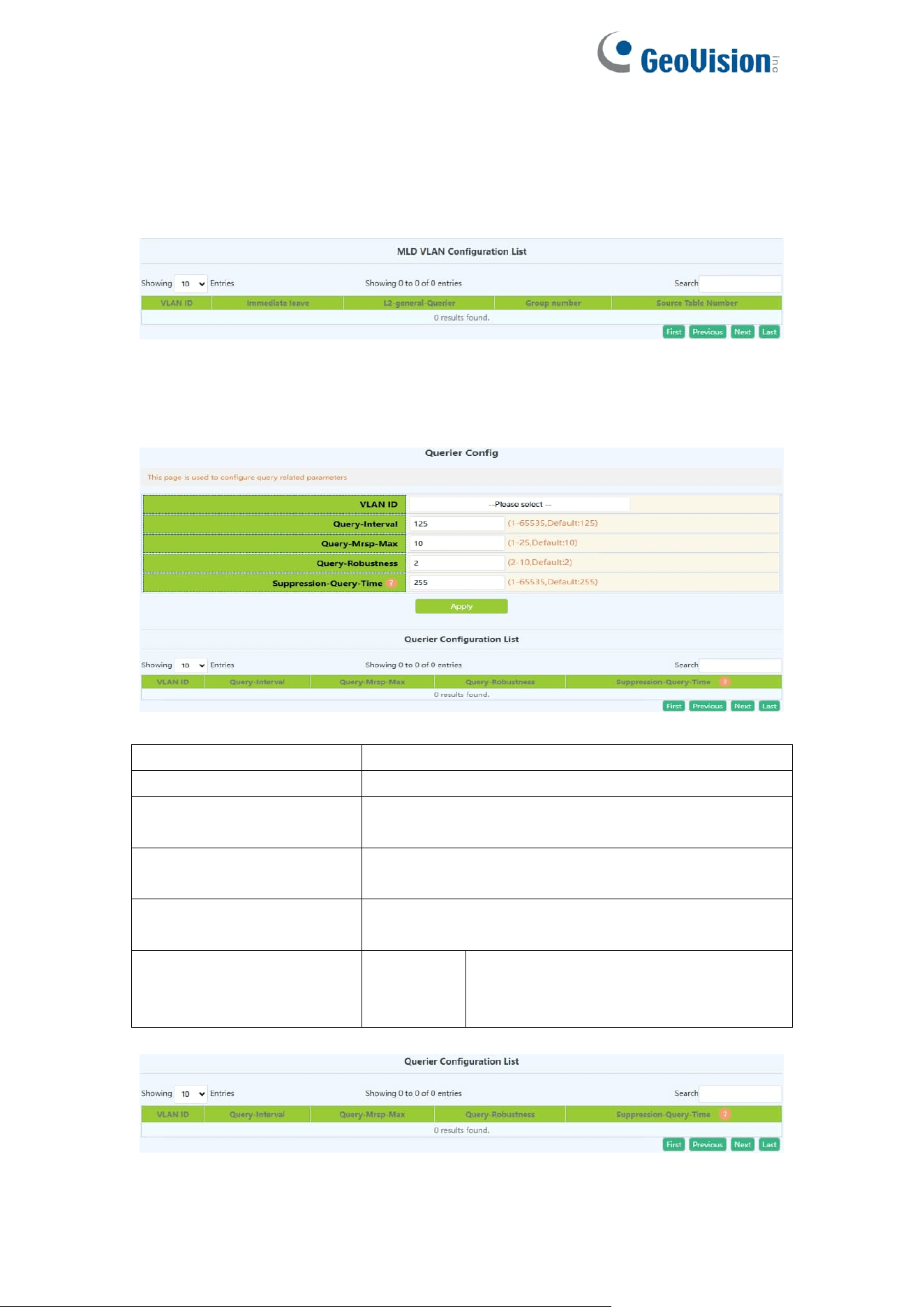
96
Note: Whether it is to configure parameters or restore the default state, it is
required to check the box at the back to take effect. The group number and the
number of source table entries are unified functions, so the two function
parameters will take effect together (when one parameter is set, the other will
be set to the default value).
Display the configuration parameters of the existing VLAN
9.2.4.Querier Config
MLD Snooping query parameter configuration.
VLAN ID
Created VLAN ID
Query-Interval
MLD Snooping query interval, range: 1-65535
Query-mrsp
configuration
Maximum response time for group query
Query-robustness
configuration
MLD Snooping robustness, range: 2-10
Suppression-query-time
configuration
Prohibited query time, range: 1-65535
Operation type
Apply
Add the mrouter port parameter
configuration checked under the
selected VLAN
Display current configuration information
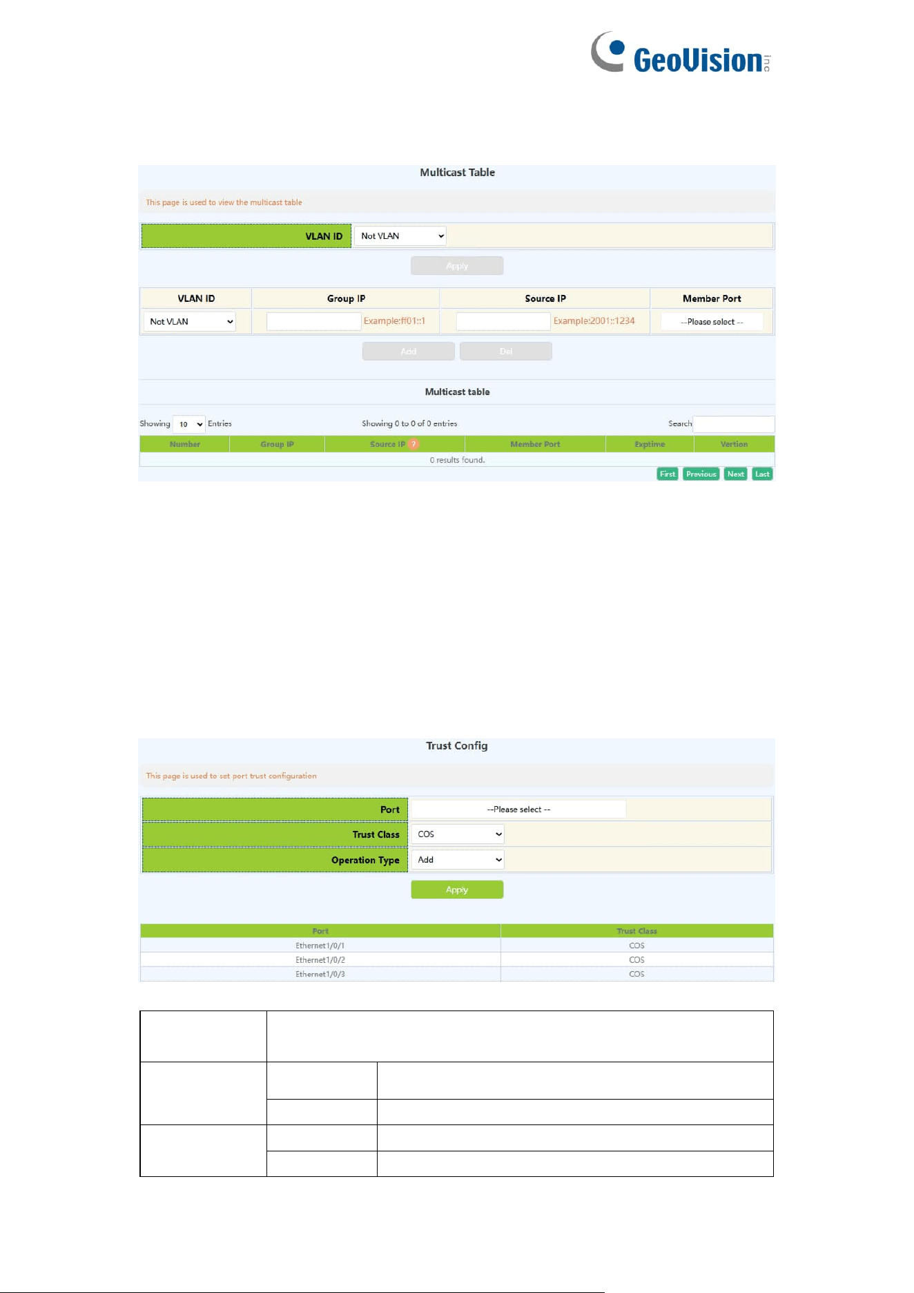
97
9.2.5.Multicast Table
The page displayed multicast table information.
10.QoS Config
10.1.Port Config
10.1.1.Trust Config
Configure port trust rules
Port
To configure the port name, click to expand the remaining
ports
Trust class
COS
Cos to int mapping based on intp field
DSCP
Intp field based on dscp to intp mapping
Operation
add
Add a trust rule for the port
Delete
Remove a trust rule for the port
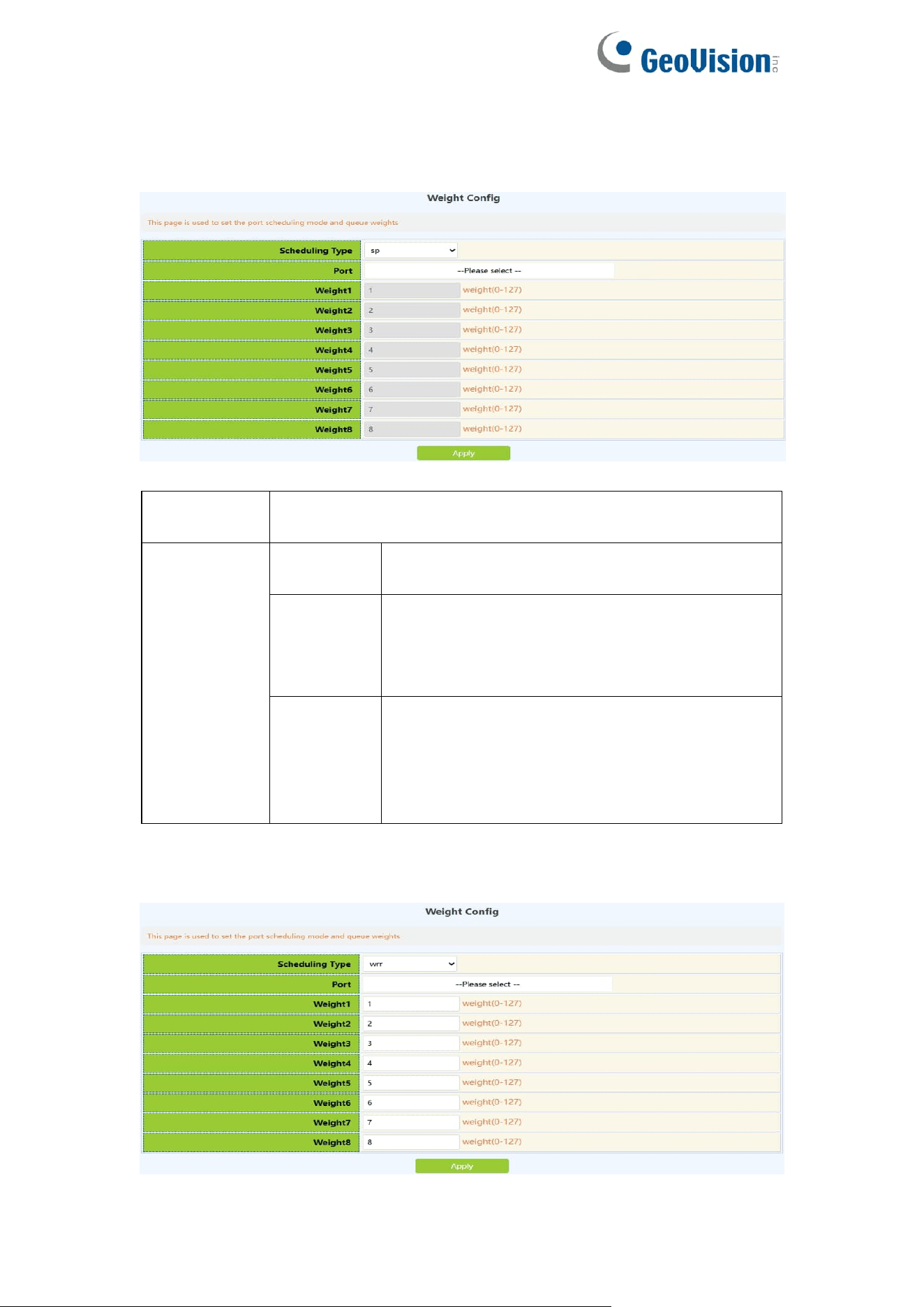
98
10.1.2.Weight Config
Configure the port to process the priority of packets according to different
queue scheduling algorithms
Port
To configure the port name, click to expand the remaining
ports
Queue
schedule
algorithm
sp
Strict queuing priority, packet transmission in
order of priority.
wrr
Weighted round-robin scheduling. Rotate
scheduling between queues to ensure that
each queue gets a certain amount of service
time
wdrr
Weighted difference round-robin scheduling,
based on message length transmission, based
on the combined effect of weight and K value
to generate the length of transmission in the
message queue
Configure the weight value of the eight queues of each port, and allocate the
number of packets according to the weight value
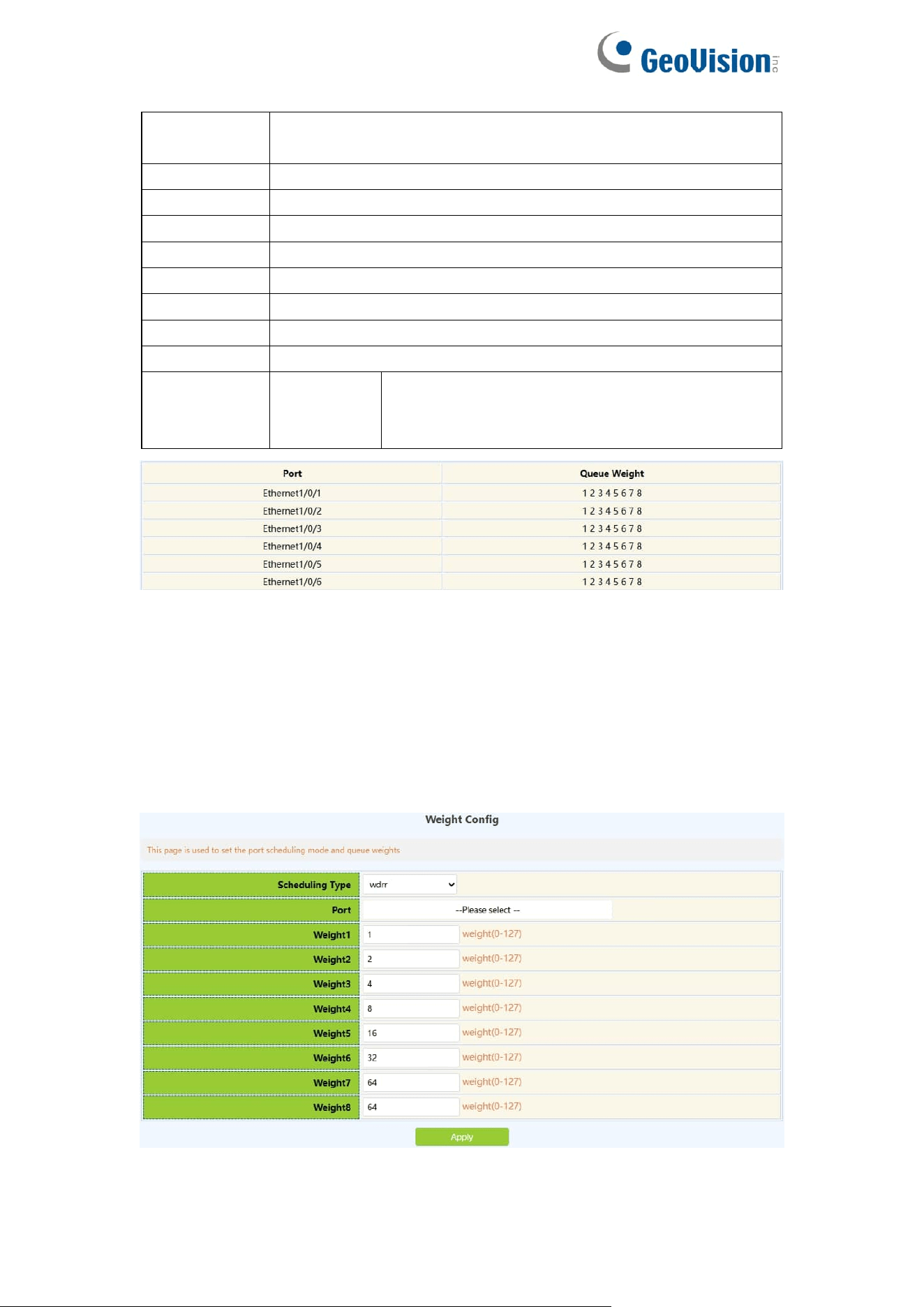
99
Port
To configure the port name, click to expand the remaining
ports
Weight1
The weight value of queue 1, the range is 0-127
Weight2
The weight value of queue 2, the range is 0-127
Weight3
The weight value of queue 3, the range is 0-127
Weight4
The weight value of queue 4, the range is 0-127
Weight5
The weight value of queue 5, the range is 0-127
Weight6
The weight value of queue 6, the range is 0-127
Weight7
The weight value of queue 7, the range is 0-127
Weight8
The weight value of queue 8, the range is 0-127
Operation
Apply
Add the weight of each queue to the port, and
fill in all the weights of each queue before
adding
Information feedback window
Configure the weight value of the eight queues of each port, transmit based on
the length of the message, and generate the transmission length in the
message queue based on the combined action of the weight and the K value
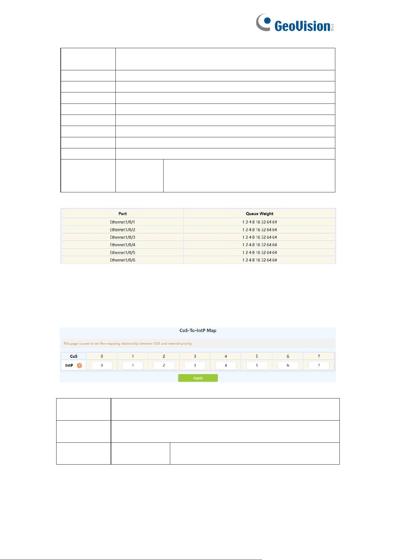
100
Port
To configure the port name, click to expand the remaining
ports
Weight1
The weight value of queue 1, the range is 0-32767
Weight2
The weight value of queue 2, the range is 0-32767
Weight3
The weight value of queue 4, the range is 0-32767
Weight4
The weight value of queue 8, the range is 0-32767
Weight5
The weight value of queue 16, the range is 0-32767
Weight6
The weight value of queue 32, the range is 0-32767
Weight7
The weight value of queue 64, the range is 0-32767
Weight8
The weight value of queue 64, the range is 0-32767
Operation
Apply
Add the weight of each queue to the port, and
fill in all the weights of each queue before
adding
Information feedback window
10.1.3.CoS-To-IntP Config
Configure the value mapped from the COS value to the internal priority
(queue).
CoS value
The COS value carried in the message or the default COS
value assigned when entering
IntP value
The value of the internal priority (queue) to which the COS
value will be mapped
Operation
type
Configuration
Configure the value of COS to IntP
Display the execution process and the current mapping relationship
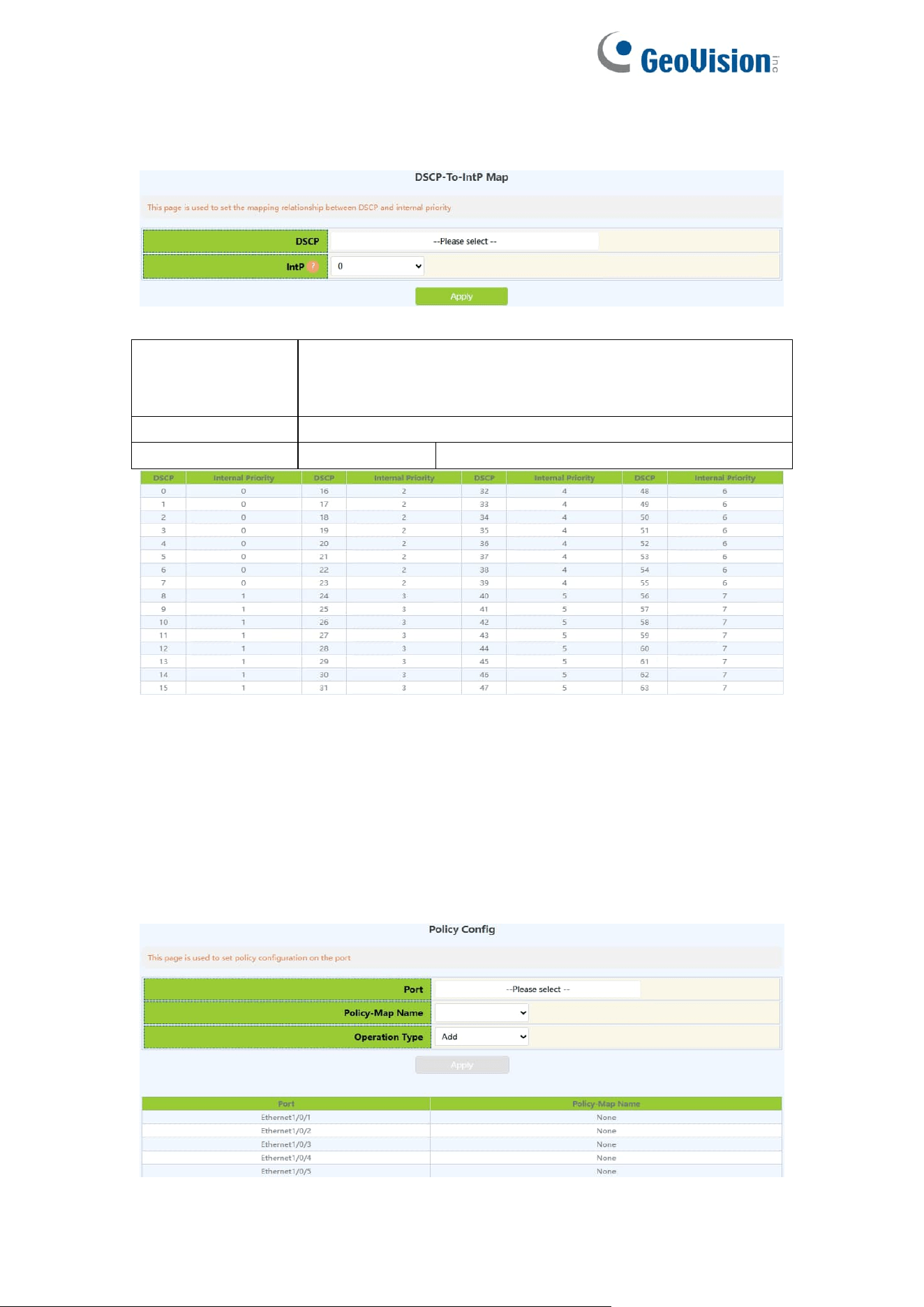
101
10.1.4.DSCP-To-IntP Config
Configure the value mapped from the DSCP value to the IntP value.
DSCP
value1-DSCP
value8(optional)
Up to eight DSCP values can be configured to the new
IntP value, among which DSCP value1 is required, DSCP
valuce2-8 is optional, range: 0-63
IntP value
New IntP value, range: 0-7
Operation type
Apply
Configure DSCP to IntP value
Shows the execution process and the current mapping relationship. The
vertical d1 represents the tens digit of DSCP, and the horizontal d2 represents
the single digit of DSCP. The value of the intersection of the two is the mapping
value.
10.1.5.Policy Config
Configure the port's policy table, and the port will process packets according to
the rules of the classification table in the policy table.
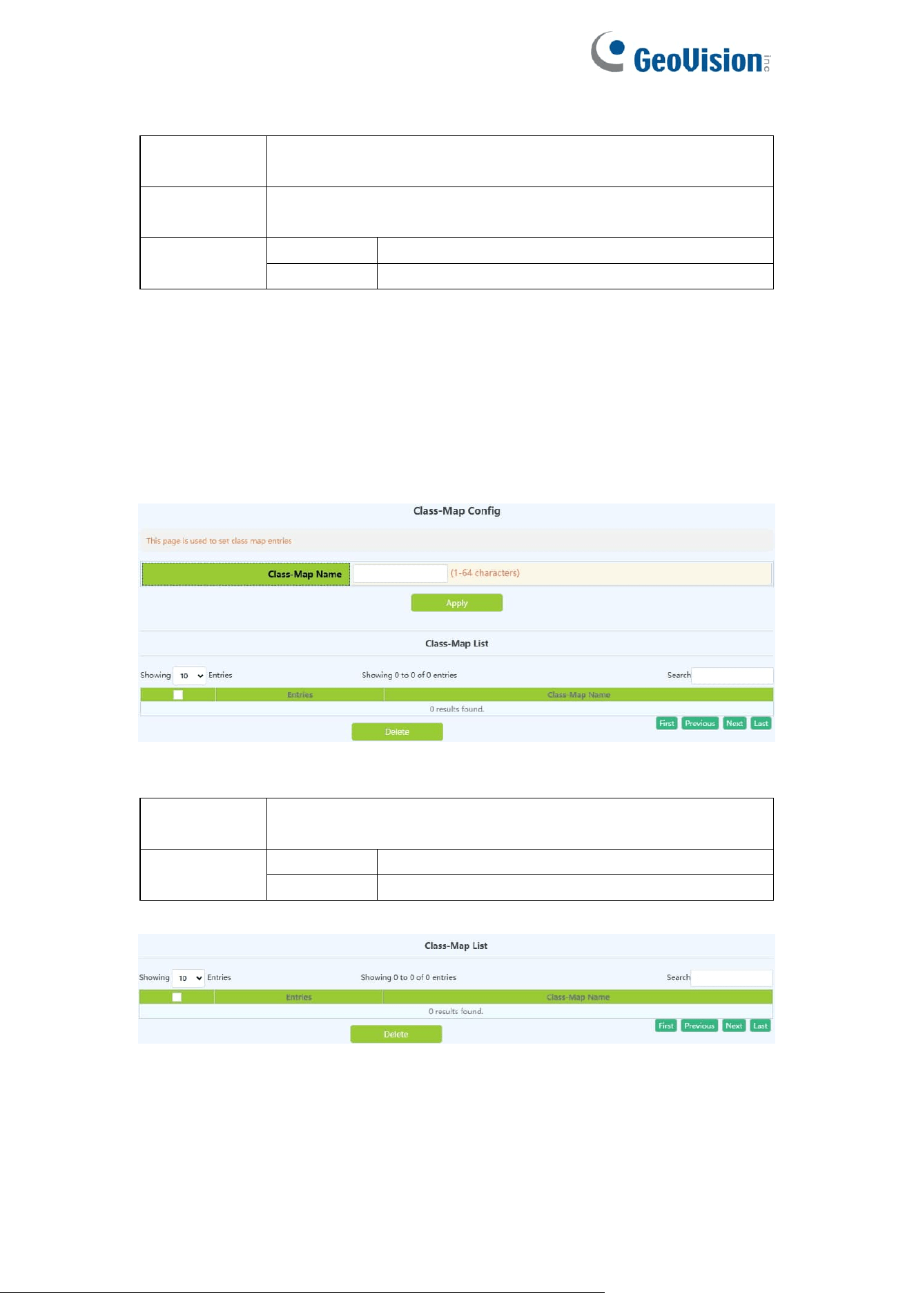
102
Port
To configure the port name, click to expand the remaining
ports
Policy map
name
The name of the policy table, added by the policy table
configuration
Operation
Add
policy for adding ports
Delete
Delete port policy
10.2.Class-Map Config
10.2.1.Class-Map Config
Create and delete classification tables, view the currently configured
classification tables
Class-map
name
Class-map name,range:1-64 character
Operation
Add
Add Class-map
Delete
Remove Class-map
Display the currently created class-map name
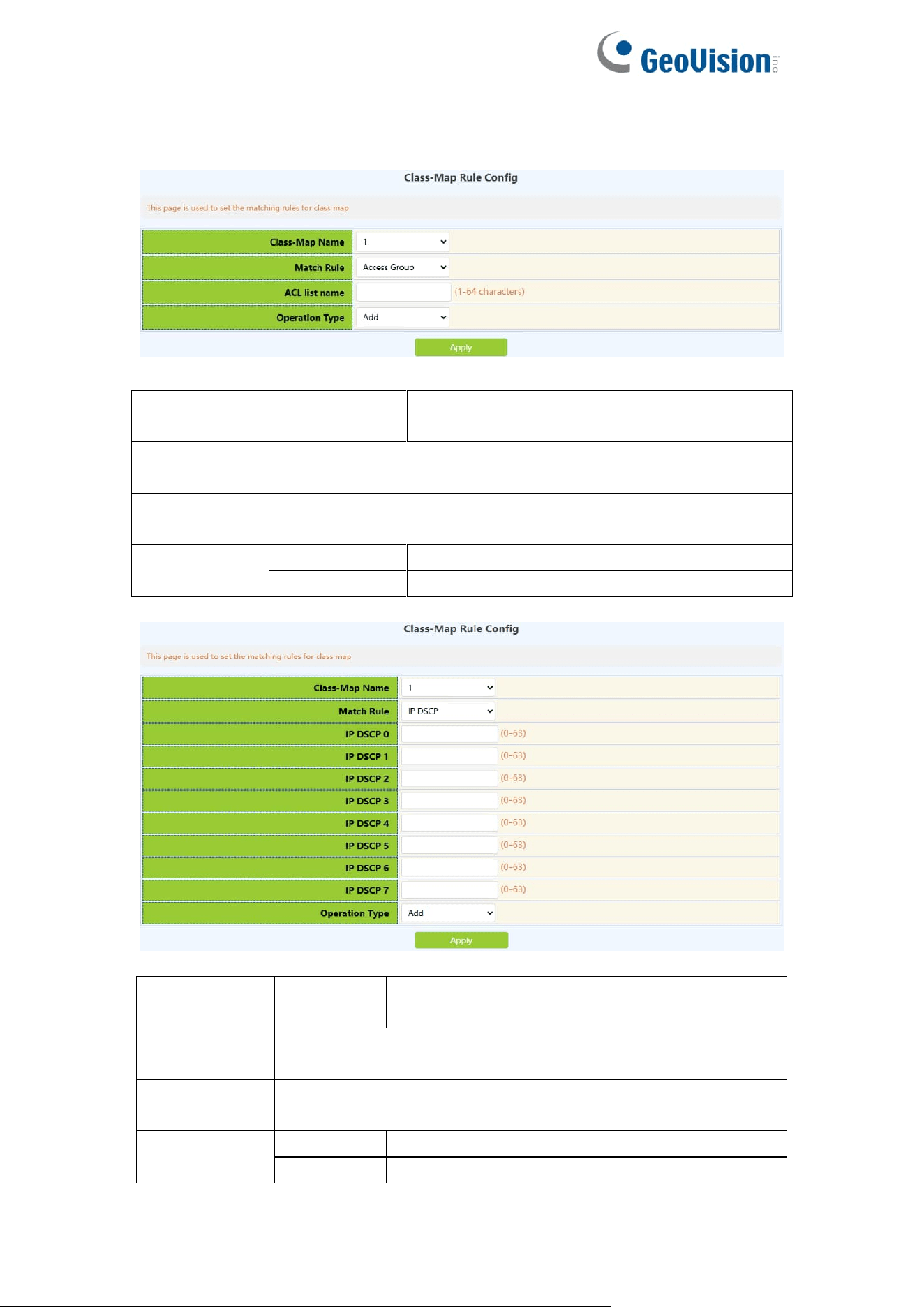
103
10.2.2.Class-Map Rule Config
Set the rules and corresponding parameters for classification matching
Classification
criteria rule
accesss-group
Match the specified IP ACL, MAC ACL or
IPv6 standard ACL or MAC-IP ACL
Class-map
name
The name of the created class-matching table, select by
clicking the drop-down
ACL list
name
Created ACL name, 1-64 characters
Operation
Add
Add matching rules
Del
Remove matching rules
Classification
criteria rule
ip dscp
Match the specified DSCP value, this
parameter is the DSCP list
Class-map
name
The name of the created class-matching table, select by
clicking the drop-down
IP dscp0-7
One or more DSCP values can be set, up to 8 DSCP values
can be set, the range is 0~63;
Operation
Add
Add matching rules
Del
Remove matching rules
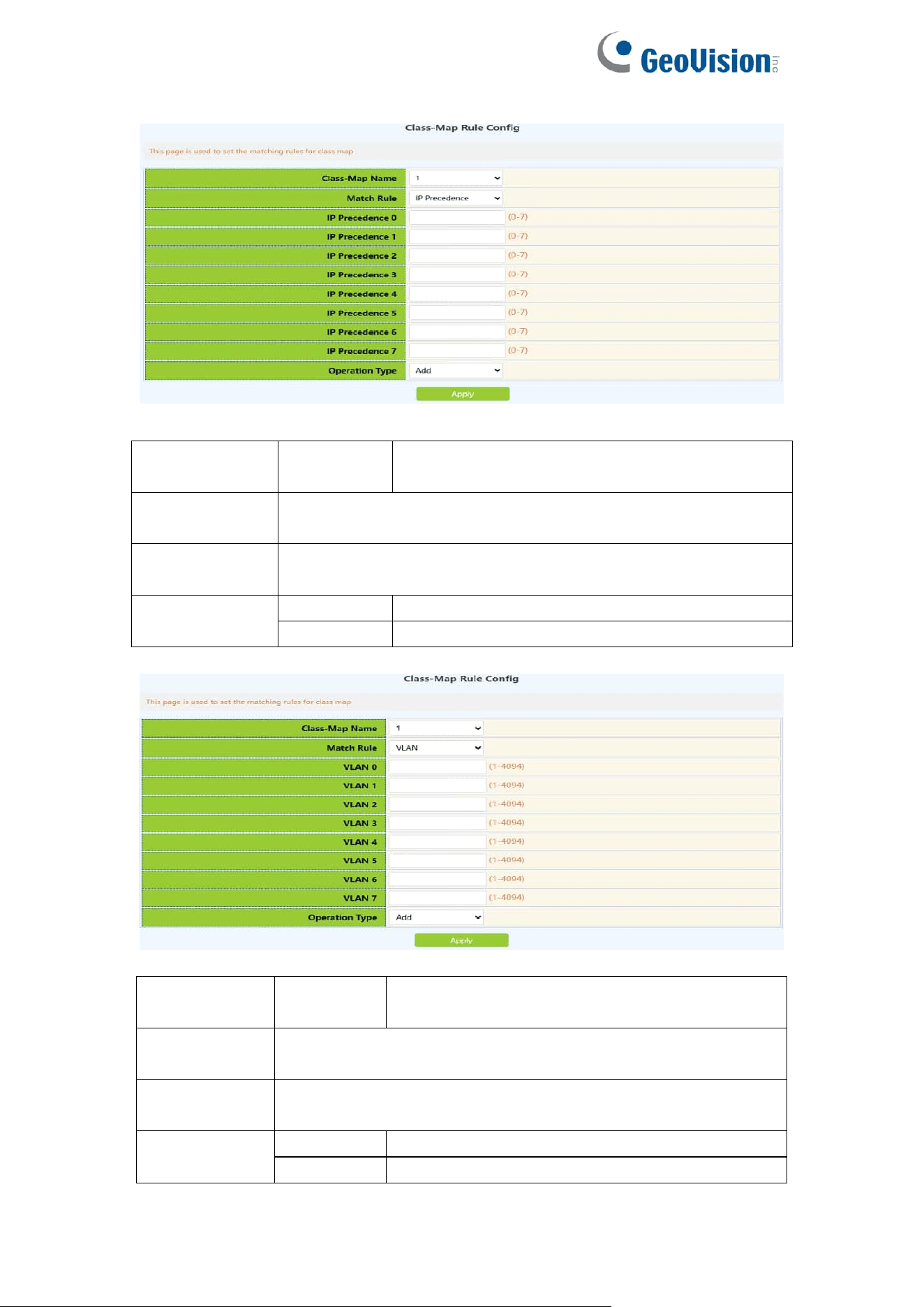
104
Classification
criteria rule
ip
precedence
Match the specified ip priority, this parameter
is the IP priority list
Class-map
name
The name of the created class-matching table, select by
clicking the drop-down
IP
precedence0-7
One or more ip priority values can be set, the list contains up
to 8 IP priority values, and the valid range is 0~7;
Operation
Add
Add matching rules
Del
Remove matching rules
Classification
criteria rule
vlan
Match the specified vlan, this parameter is a
list of vlan id
Class-map
name
The name of the created class-matching table, select by
clicking the drop-down
Vlan0-7
One or more VLAN IDs can be set, including 8 VLAN IDs at
most, ranging from 1 to 4094
Operation
Add
Add matching rules
Del
Remove matching rules
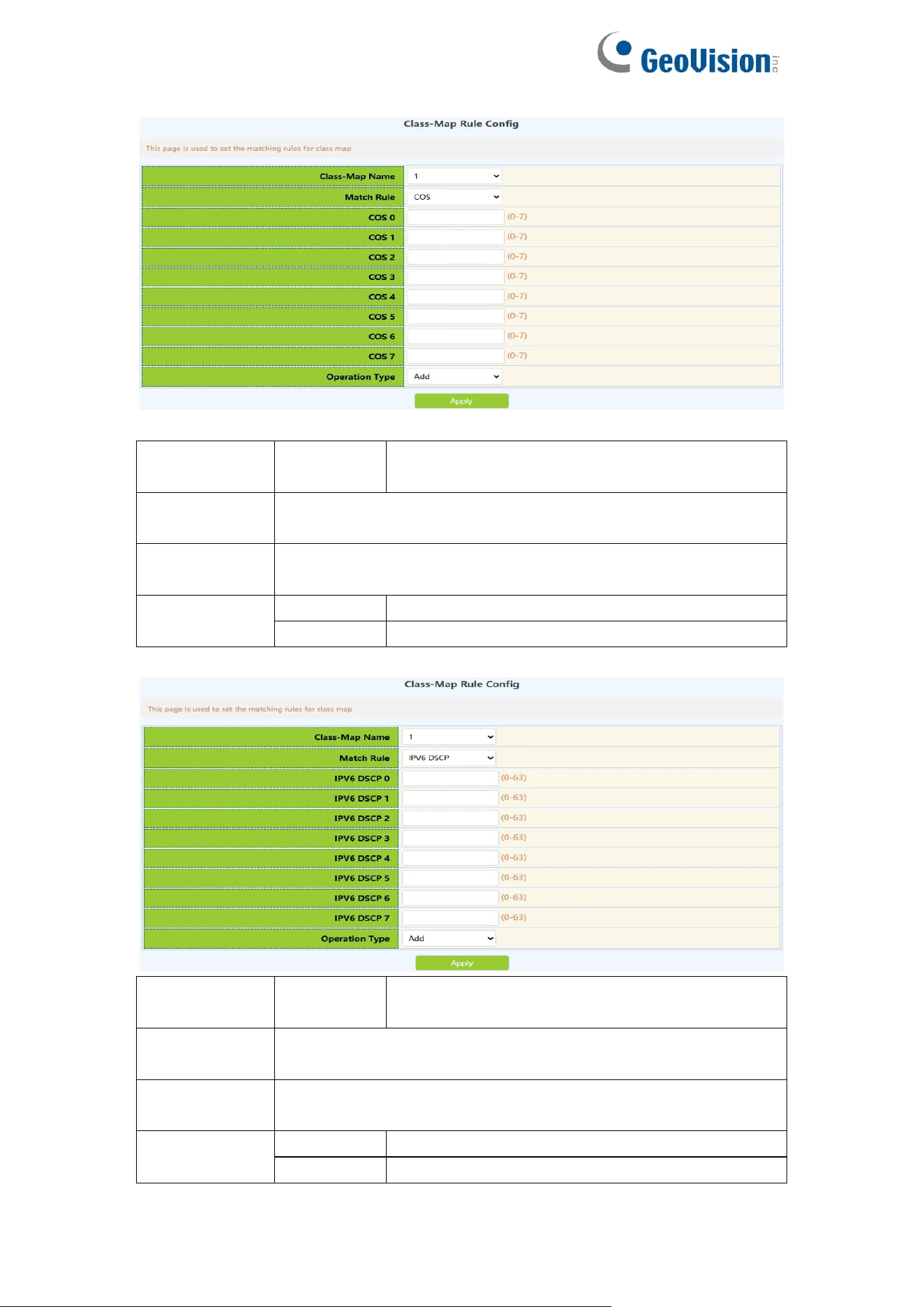
105
Classification
criteria rule
cos
Match the specified CoS value, this parameter
is a list of vlan id
Class-map
name
The name of the created class-matching table, select by
clicking the drop-down
Cos 0-7
One or more cos values can be set, the parameter is a CoS
list composed of up to 8 CoS, the range is 0~7;
Operation
Add
Add matching rules
Del
Remove matching rules
Classification
criteria rule
ipv6 dscp
Match the specified ipv6 DSCP value, this
parameter is the ipv6 DSCP list
Class-map
name
The name of the created class-matching table, select by
clicking the drop-down
IPv6 dscp0-7
One or more ipv6 DSCP values can be set, up to 8 DSCP
values can be set, the range is 0~63;
Operation
Add
Add matching rules
Del
Remove matching rules
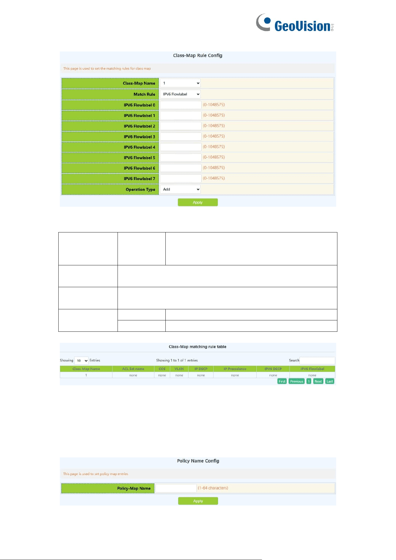
106
Classification
criteria rule
ipv6
flowlabel
Match the specified IPv6 flow label, this
parameter is the value of the IPv6 flow label
DSCP list
Class-map
name
The name of the created class-matching table, select by
clicking the drop-down
IPv6
flowlabel0-7
One or more IPv6 flowlabel values can be set, ranging from
0 to 1048575;
Operation
Add
Add matching rules
Remove
Remove matching rules
10.3.Policy-Map Config
10.3.1.Policy Name Config
Create and delete policy tables, and collaborate with classification tables to
create packet in and out rules
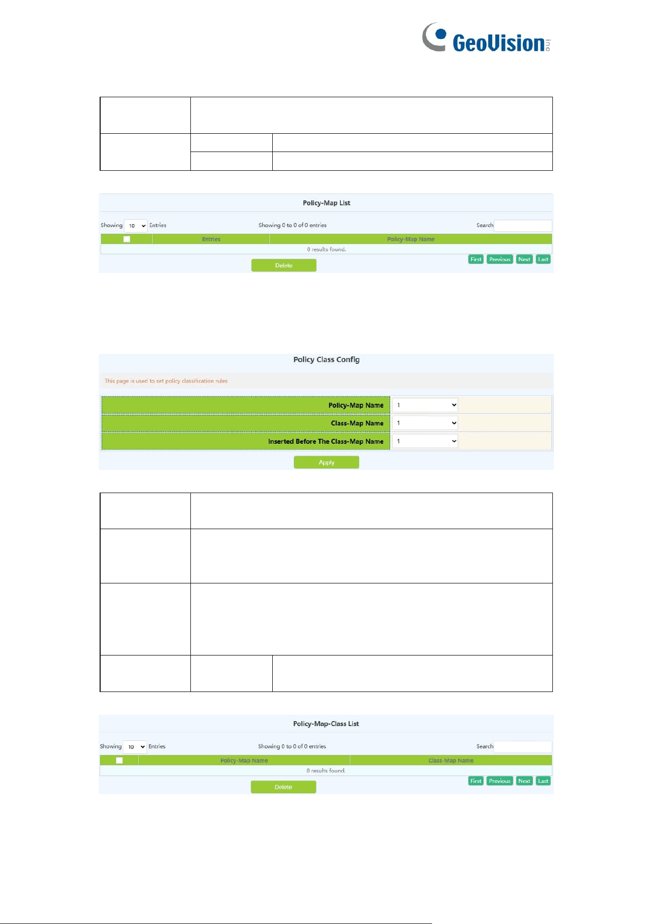
107
Policy-map
name
Policy-map name,range:1-64 character
Operation
Apply
Add policy-map
Delete
Remove policy-map
Display the currently created policy-map.
10.3.2.Policy Class Config
Apply the class-map to the policy-map.
policy-map
name
The name of the created policy-map
class-map
name
The name of the classification table created by the
classification matching table, this table will be applied to the
policy -map
Inserted
before the
class-map
name
Prior to the insertion of the classification matching table, the
name of the classification table that has been applied to the
strategy table, and the priority of the newly applied
classification matching table is increased
Operation
Add
Add an association between the strategy table
and the classification table
Display the association between the created policy table and the classification
matching table

108
10.3.3.Policy Mark Config
Configure the priority of packets in the policy mapping configuration mode.
Assign a new DSCP and IP priority to the classified traffic. Only the classified
traffic that meets the matching criteria will be assigned a new value.
Classification
criteria rule
ip dscp
Set the DSCP value again
according to the rules defined in the
policy-map and class-map
ip precedence
Set the IP priority again according
to the rules defined in the
policy-map and class-map
drop-precedence
Set the discarding priority again
according to the rules defined in the
policy-map and class-map
internal-priority
Set the internal priority again
according to the rules defined by
the policy-map and class-map
cos
Set the COS value again according
to the rules defined by the policy
table and the classification
matching table
Policy-map name
The name of the created policy table
Class-map name
Created classification match table
DSCP
DSCP value, range: 0-63
Precedence
IP priority,range:0-7
Drop-precedence
drop priority, range: 0-2
Internal-priority
internal priority, range: 0-7
COS
COS value, range: 0-7
Operation
Add
Add the priority and queue value
associated with the strategy table
and the classification matching
table
Delete
Remove the priority and queue
value associated with the strategy
table and the classification
matching table
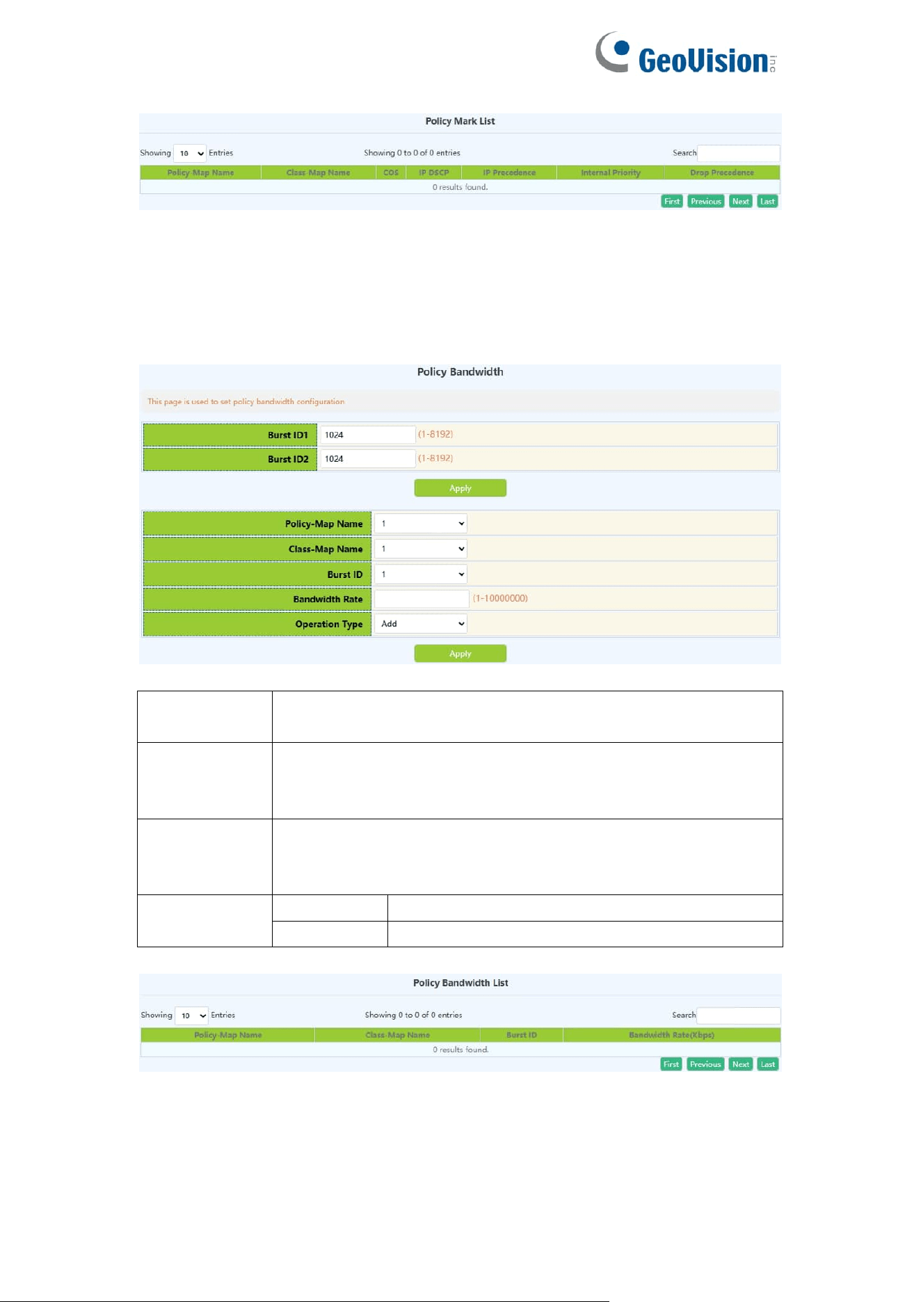
109
10.3.4.Policy Bandwidth
Configure the new aggregation strategy and the information rate and burst id
of the aggregation strategy.
Aggregate
policer name
New aggregate policer name, range: 1-64 character.
Committed
Information
Rate
Information Rate, range: 1-10000000kbit/s
Policy burst
id
configuration
Burst id configuration, range: 1-2
Operation
Add
Add aggregate policer
Remove
Remove aggregate policer
10.3.5.Policy VLAN
Configure VLAN Association Policy.
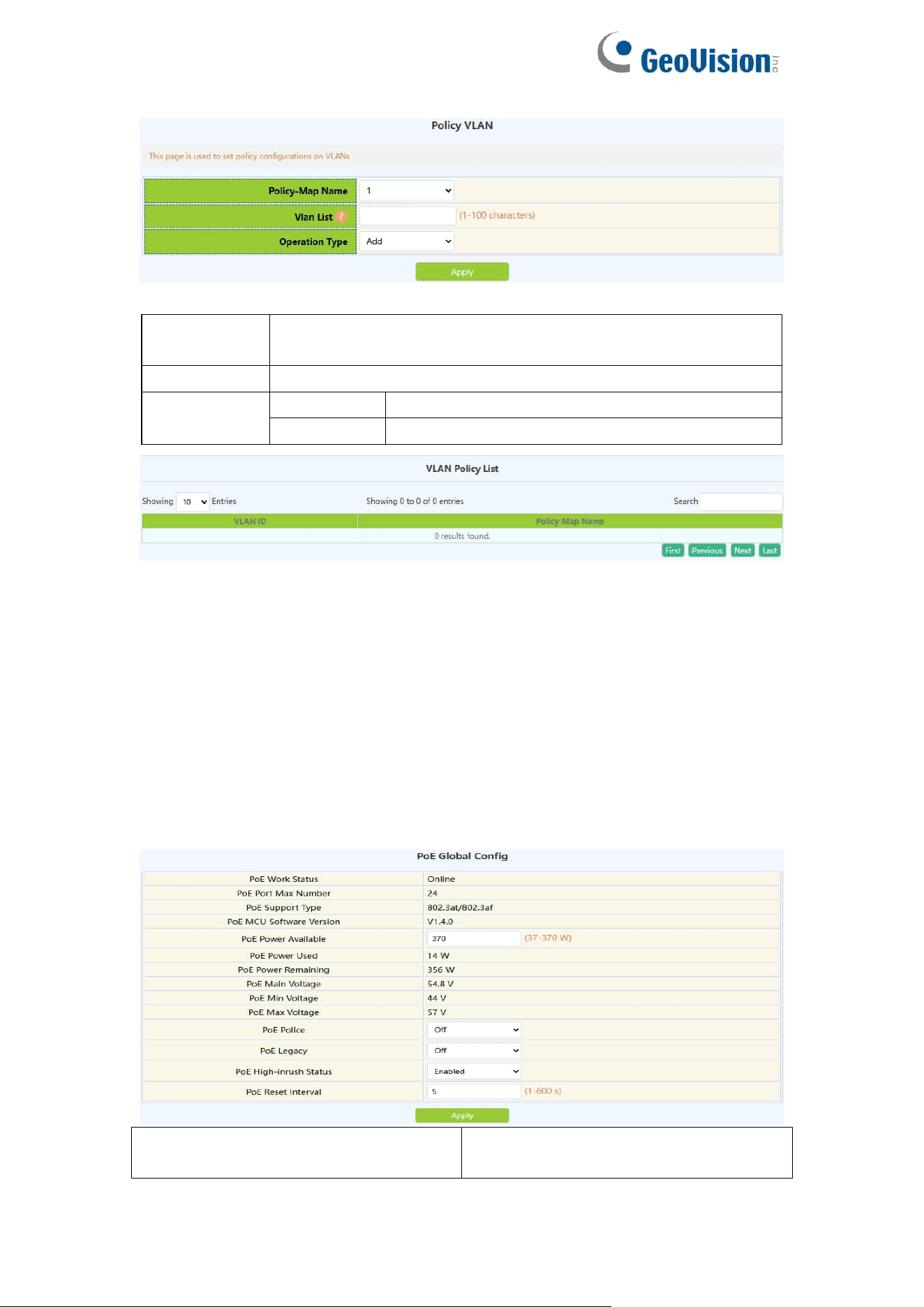
110
Policy-map
name
The name of the created strategy, select by clicking the
drop-down
VLAN List
VLAN ID, range: 1-4094
Operation
Add
Add VLAN-based policy
Remove
Remove VLAN-based policy
11.PoE Config
11.1.PoE Global Config
This page can be used to globally configure poe properties and view poe
global property information.
To display the “PoE Global Config” page,click PoE Config ->PoE Global
Config,click "Apply" to configure.
PoE Power Available
Maximum power supported by current
switches
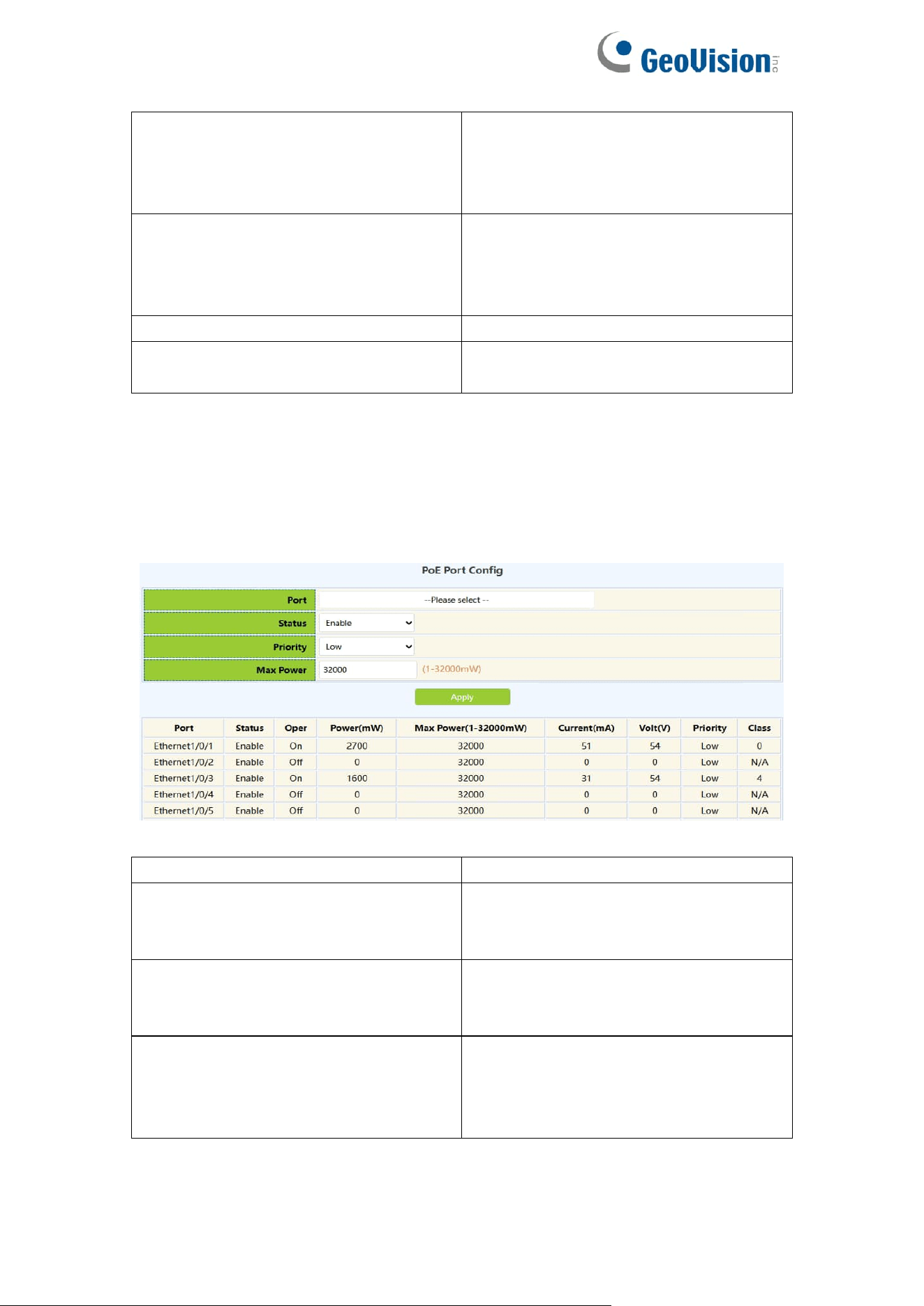
111
PoE Police
Enable status of priority power supply
policy:
Off:disable
On:enable
PoE Legacy
Current status of standard PD
detection function:
Off:disable
On:enable
PoE High-inrush Status
Enable/Disable
PoE Reset Interval
Port reset time range :1-600 per
second
11.2.PoE Port Config
This page can be used to configure PoE properties under ports.
To display the “PoE Port Config” page,click PoE Config ->PoE Port Config,
click "Apply" to configure.
Port
Current configured Ethernet ports
Status
Enable:Normal power supply
Force:Forced power supply
Disable:No power supply
Priority
Low:low priority
High:high priority
Critical:highest priority
Max Power
Sets the maximum output power
supported by the current port, size
range :1-32000, unit mW;For
example: 100、200、3000
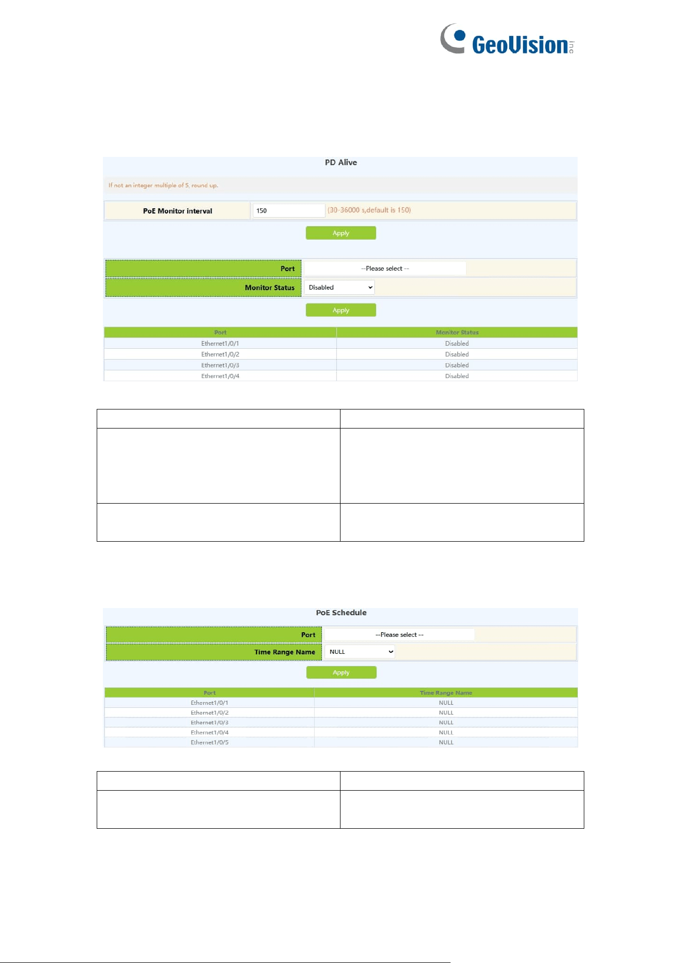
112
11.3.PD Alive
This page can be used to configure poe pd alive under ports.
Interface
Current configured Ethernet ports
PoE Monitor Interval
Check whether the PD connected to
the current port is in the detection
interval of normal communication,
range: 30-36000 seconds
PoE Monitor Status
Disabled:disable port monitoring
Enabled:Enable port monitoring
11.4.PoE Schedule
Interface
Current configured Ethernet ports
Time range name
The time range name defined by the
switch