
www.klarstein.com
TITANSTEEL
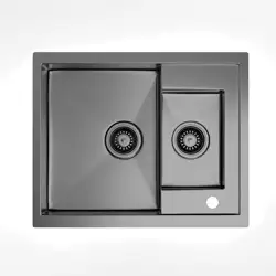
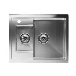
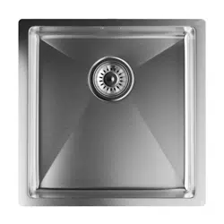
Küchenspüle 40x40
Kitchen Sink 40x40
Évier de cuisine 40x40
Lavandino da cucina 40x40
Fregadero de cocina 40x40
10046017


3
DE
ARTIKEL
Artikelnummer 10046017
INHALTSVERZEICHNIS
Lieferumfang 4
Unterbauinstallation 6
Abussset Installation 11
Prüfen der Dichtungsleistung und Reinigung 15
Sehr geehrter Kunde,
wir gratulieren Ihnen zum Erwerb Ihres Gerätes.
Lesen Sie die folgenden Hinweise sorgfältig durch und
befolgen Sie diese, um möglichen Schäden vorzubeugen.
Für Schäden, die durch Missachtung der Hinweise und
unsachgemäßen Gebrauch entstehen, übernehmen wir
keine Haftung. Scannen Sie den folgenden QR-Code,
um Zugriff auf die aktuellste Bedienungsanleitung und
weitere Informationen rund um das Produkt zu erhalten

4
DE
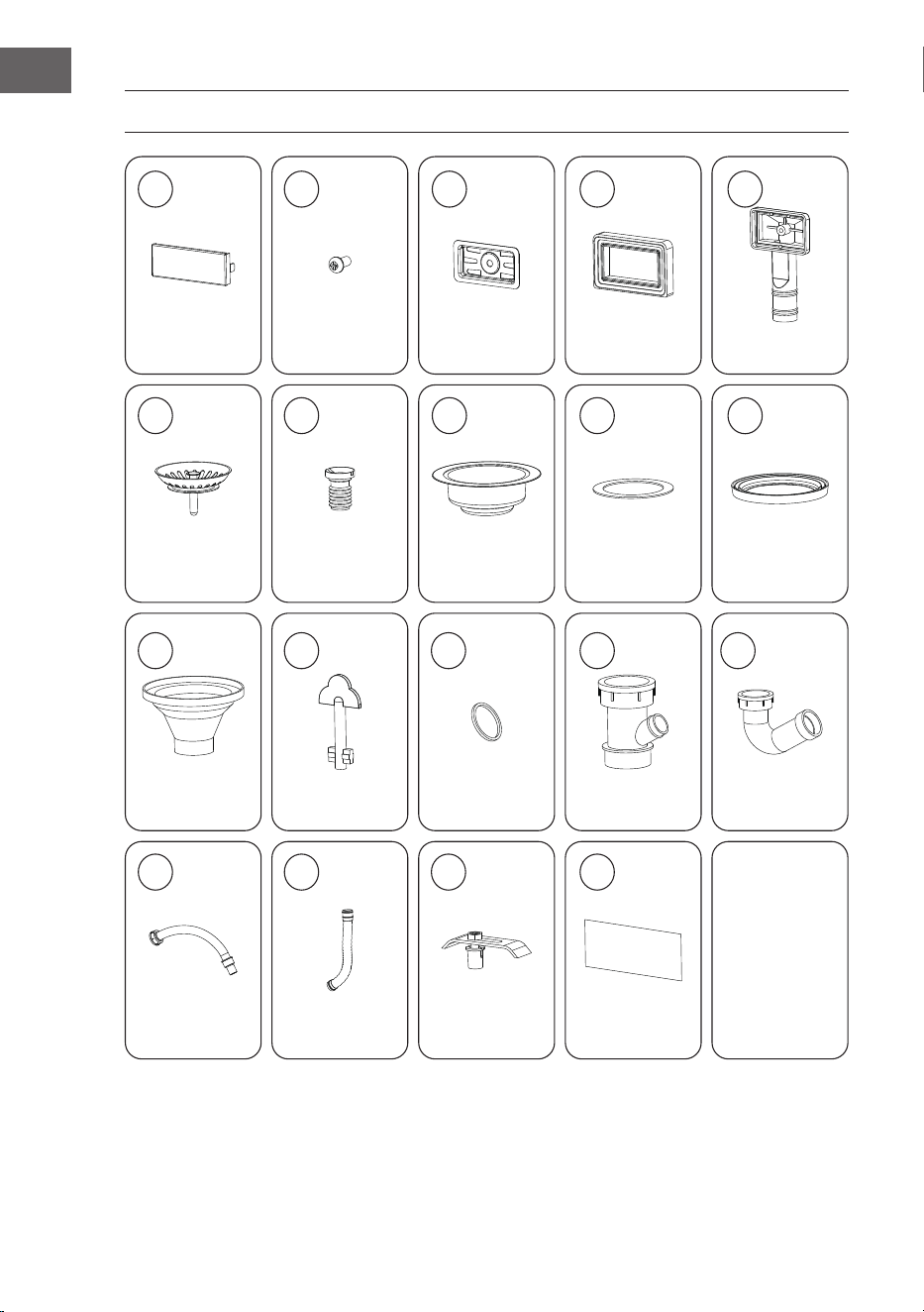
LIEFERUMFANG
x1 x1 x1 x1 x1
x1 x1 x1 x1 x1
x1 x1 x3 x1 x1
x1 x1 x6 x1
T
C
E
UT-OUT
MPLAT
E
1 2
3 4 5
6 7 8 9 10
11 12 13 14 15
16 17 18 19
5
DE
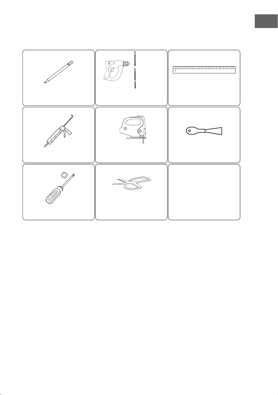
Werkzeuge
Pencil x1
Silicon x1
Screw driver x1 Scissor x1
Electric saw x1
Electric drill x1
⌀10 mm
⌀20 mm
⌀ 3 mm
Ruler x1
Shovel x1
BleistiftBleistift BohrerBohrer ZollstockZollstock
SilikonSilikon elektrische Sägeelektrische Säge SpatelSpatel
SchraubenzieherSchraubenzieher SchereSchere
6
DE
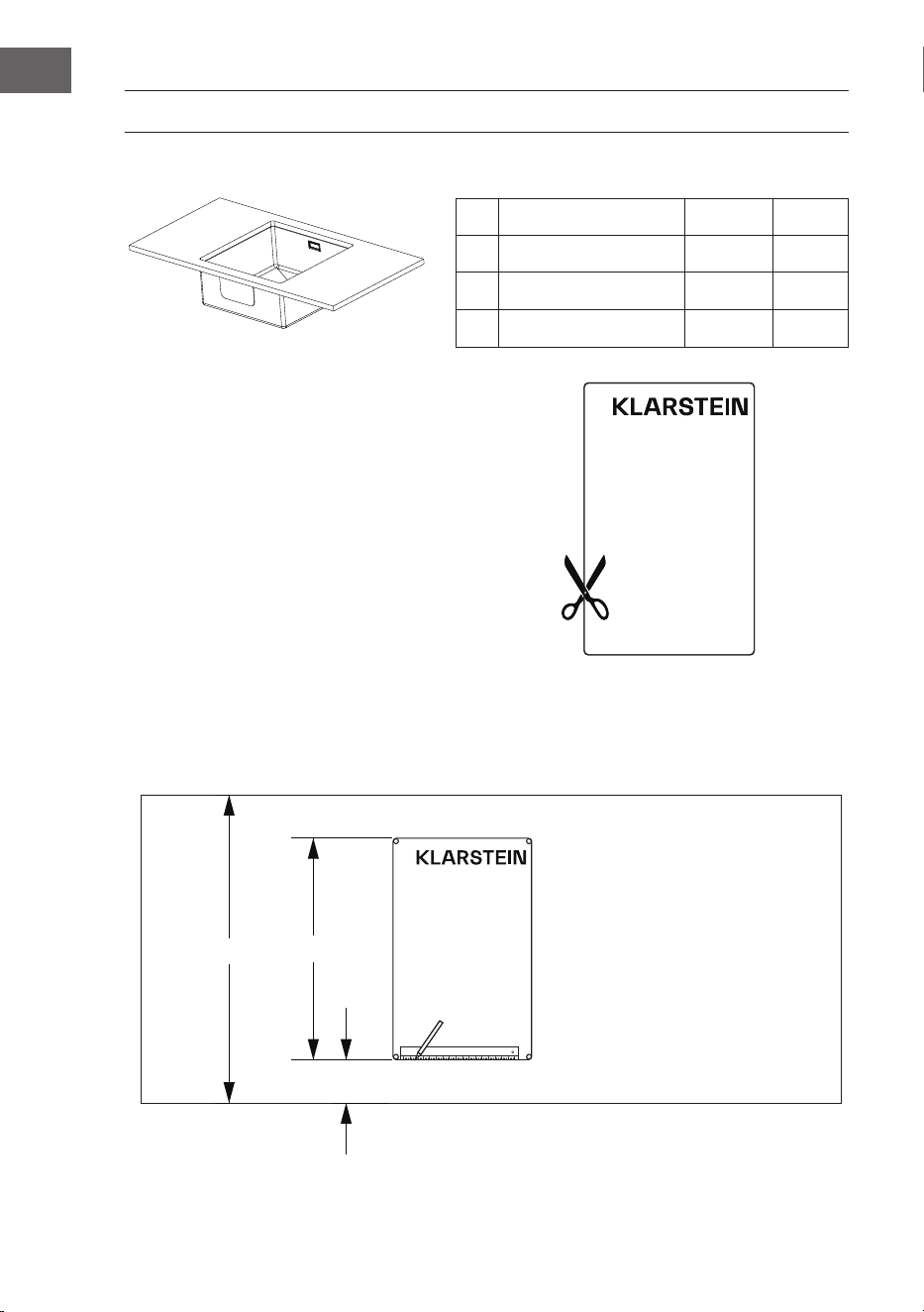
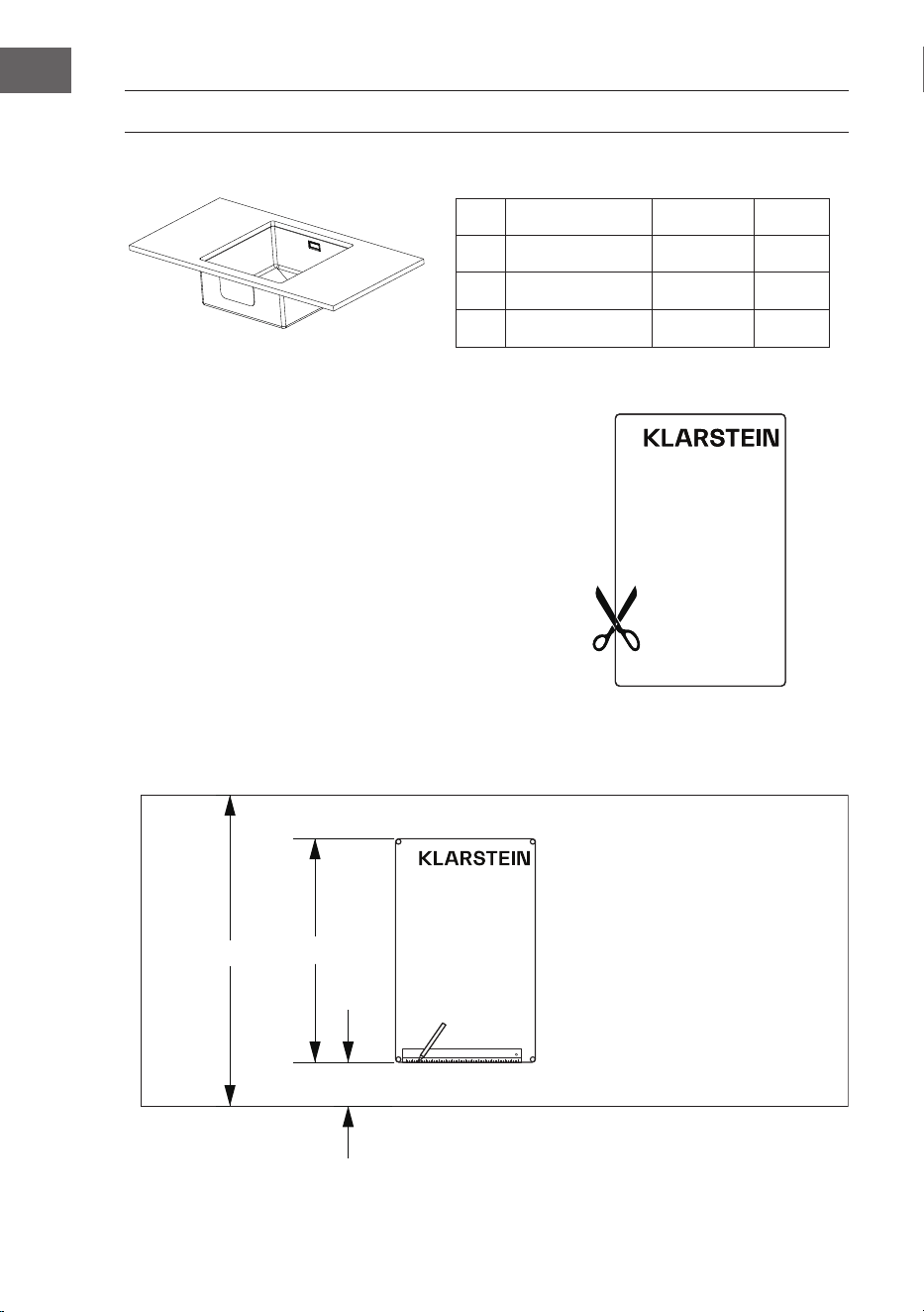
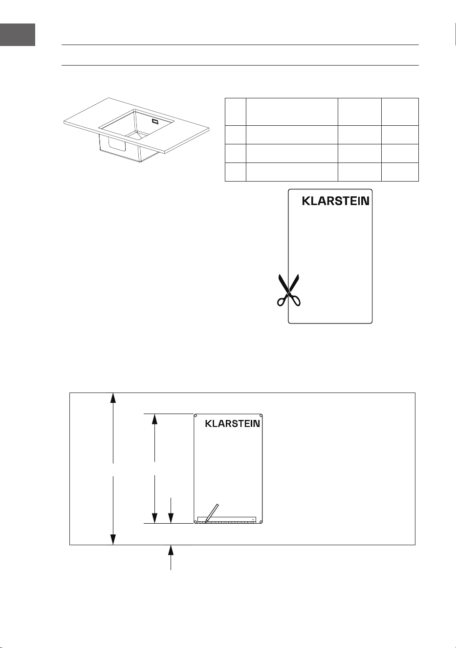
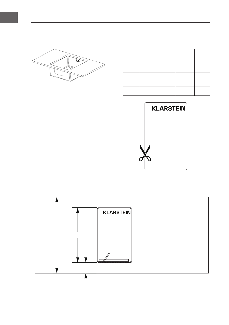
UNTERBAUINSTALLATION
Nr. Beschreibung Referenz
Anzahl
A Küchenspüle 1
B Unterputzklemmen
⑱
1
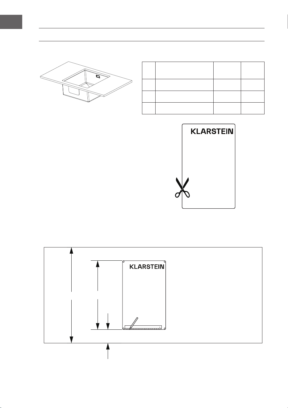
C Ausschneideschablone
⑲
1
1. Schneiden Sie die Ausschneideschablone entlang der
Markierung mit einer Schere aus.
ALPMET TUO-TUC TUC ETETALPMET TUO-
2. Legen Sie die Ausschneideschablone auf die Arbeitsplatte und zeichnen Sie mit einem Bleistift
und einem Zollstock an der Markierung der Schablone entlang.
650mm
125mm
400mm
CUT-OUT TEMPLATE
Schablone ach auegen.
Ausschneide
Schablone
Ausschneide-
Schablone

7
DE
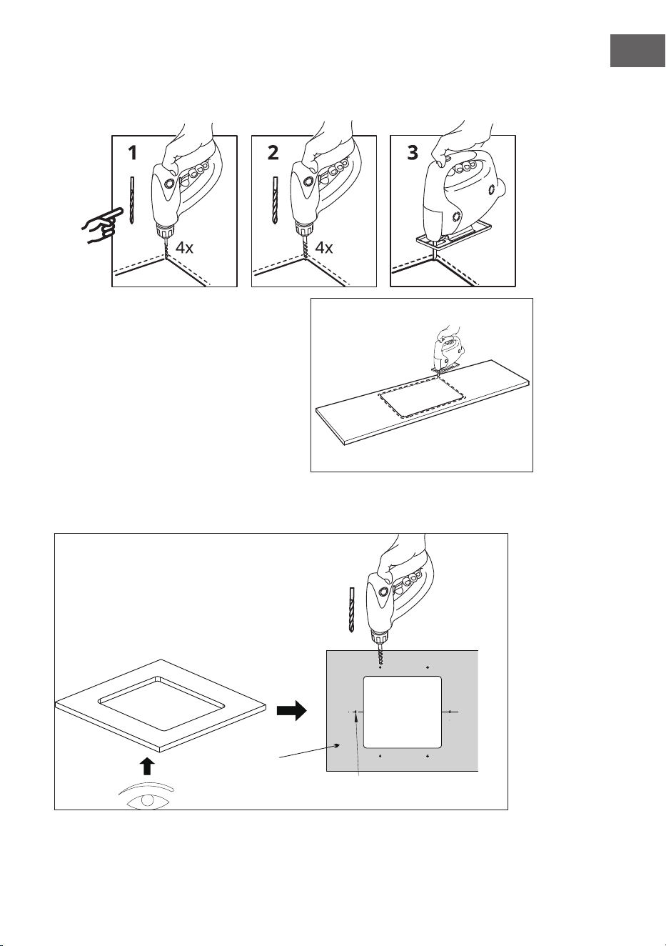
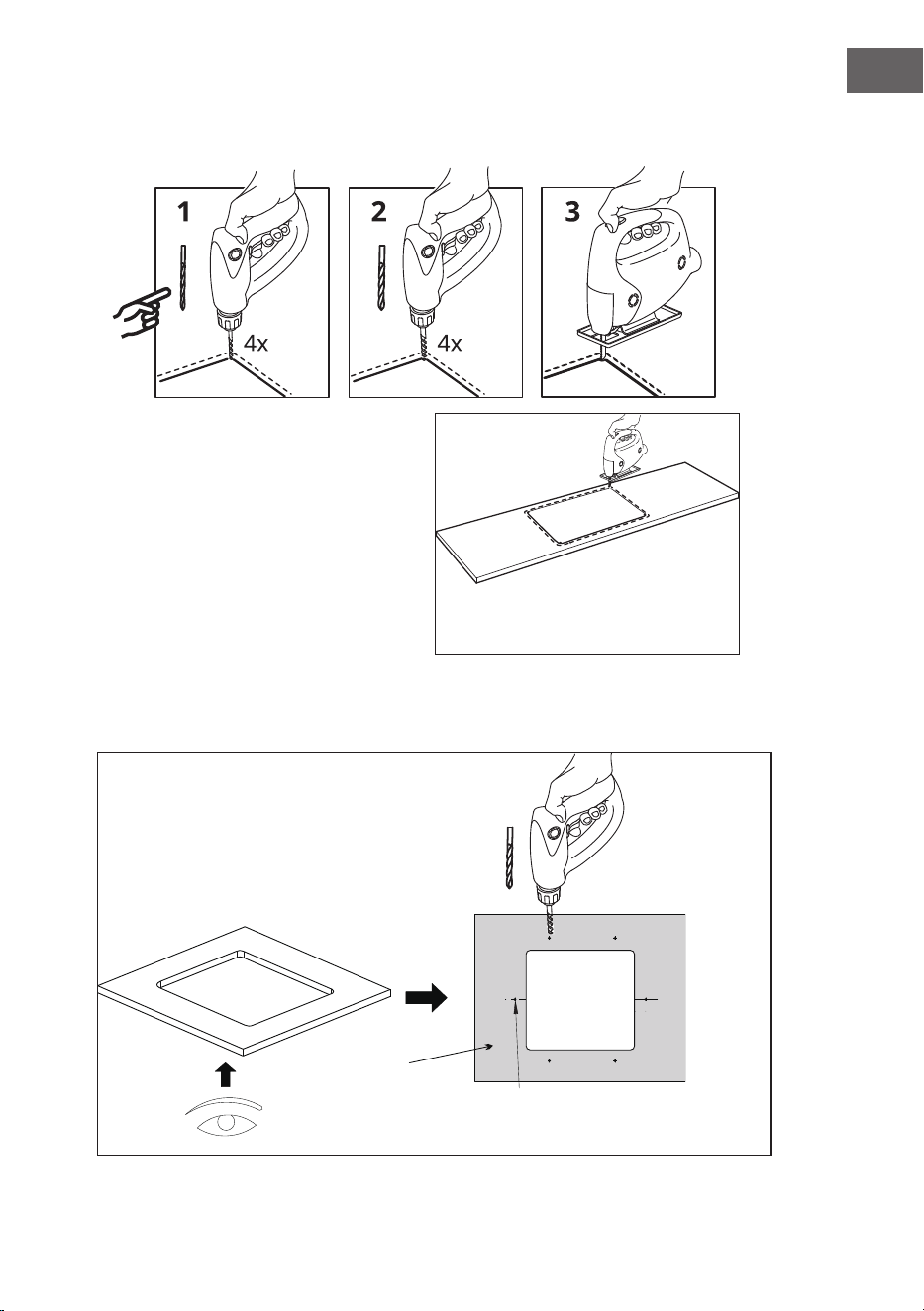
3. Bohren Sie mit einem elektrischen Bohrer 4 kleine Löcher. Bohren Sie die Löcher zunächst mit
einem Aufsatz mit
⌀3 vor und anschließend mit einem Aufsatz mit ⌀20.
⌀3 mm ⌀20mm
4. Schneiden Sie die Arbeitsplatte entlang
der Markierung mit einer elektrischen
Säge aus.
5. Bohren Sie die entsprechende Anzahl von Löchern gemäß den Abmessungen der Spüle auf der
Rückseite der Arbeitsplatte mit einer elektrischen Bohrmaschine. Beachten Sie den Abstand
zwischen Löchern und Linien.
⌀10 mm
Unterseite der
Arbeitsplatte
Lochgröße:
⌀10 mm mit 15 mm Tiefe

8
DE
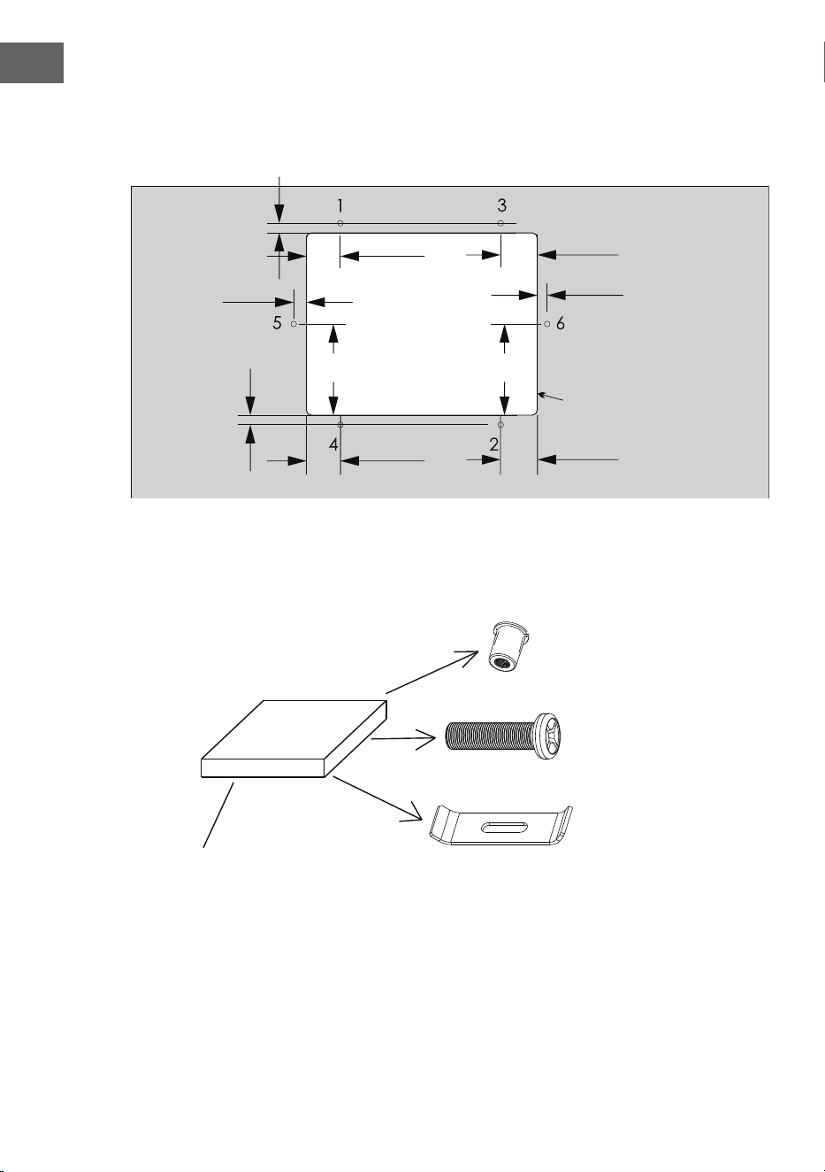
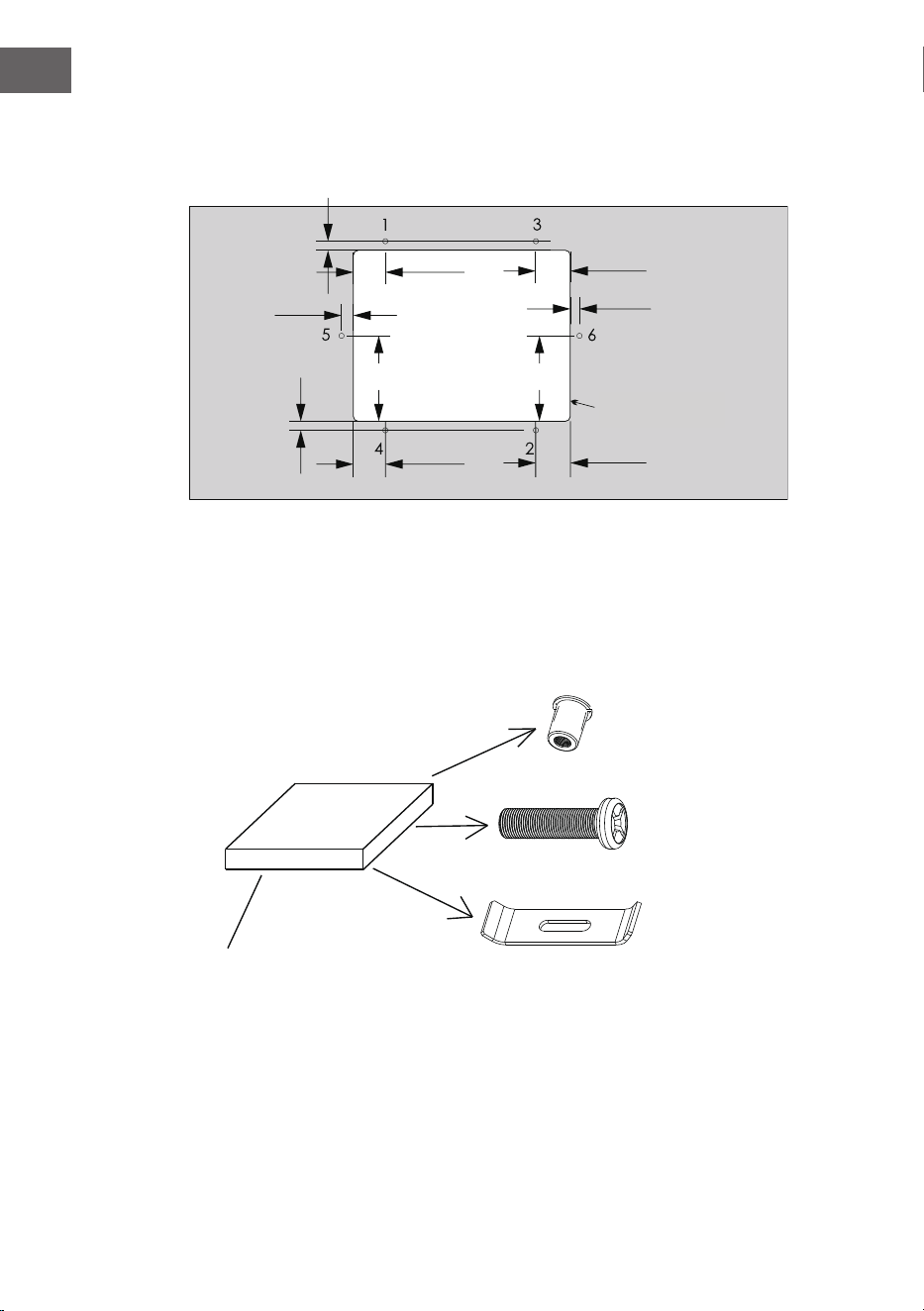
6. Bohren Sie gemäß der folgenden Abbildung 6 φ10mm große Löcher mit einer Tiefe von 15 mm
auf der Rückseite der Arbeitsplatte rund um die Öffnung herum.
130mm
200mm
45mm
45mm
130mm
200mm
45mm
45mm
130mm
130mm
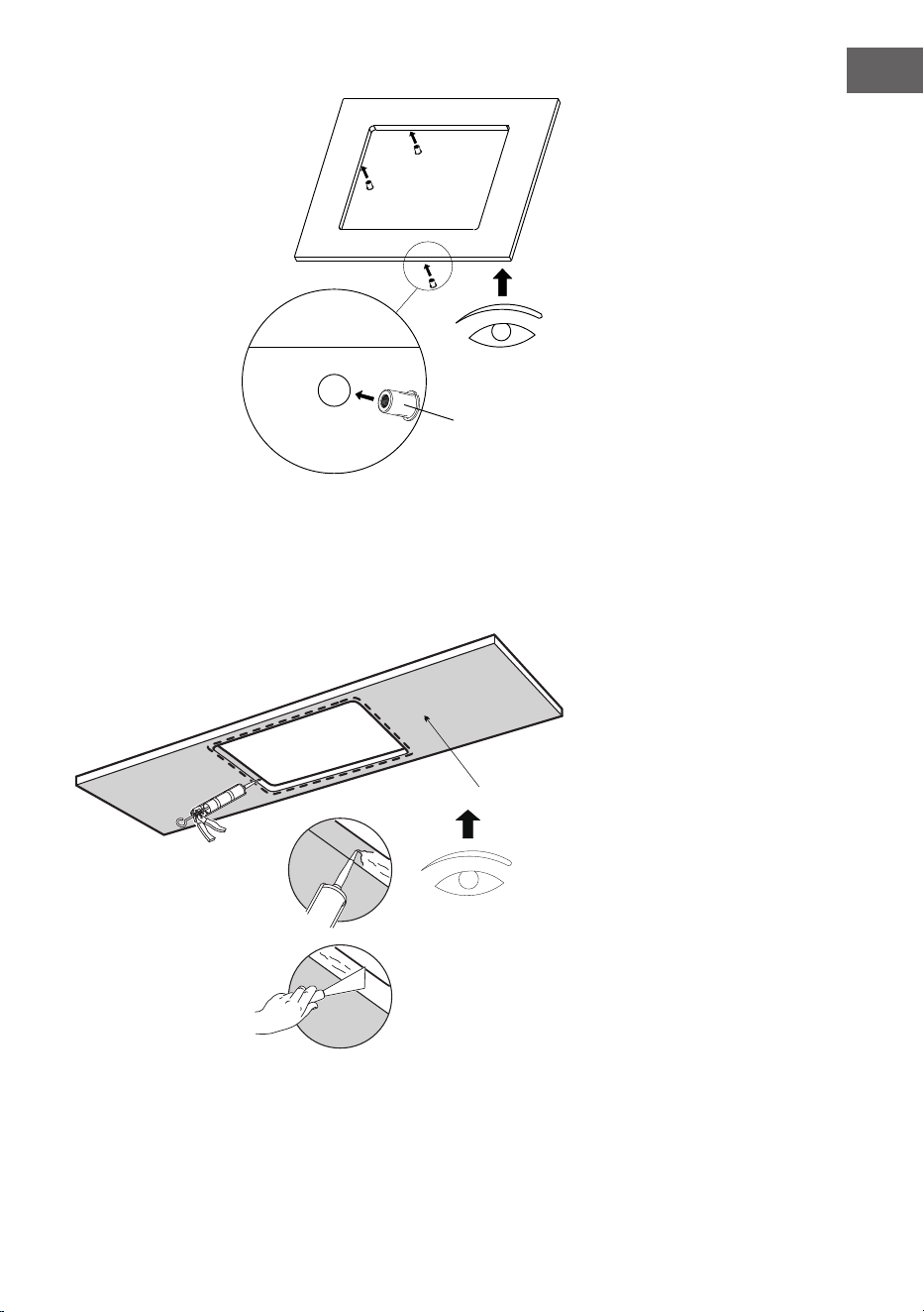
7. Öffnen Sie die Unterbauklammern, nehmen Sie die Dübel heraus und setzen Sie sie in die
Löcher unter der Arbeitsplatte ein.
Kante der Arbeitsplatte
⑱
B1 Dübel
B2 Schraube
B3 Halterung
Unterbauklammern

9
DE
Unterseite der Arbeitsplatte
B1
8. Legen Sie eine Schicht Silikon entlang der Schnittlinien auf die Rückseite der Arbeitsplatte und
streichen Sie das Silikon ab, damit es gleichmäßig und eben ist.

10
DE
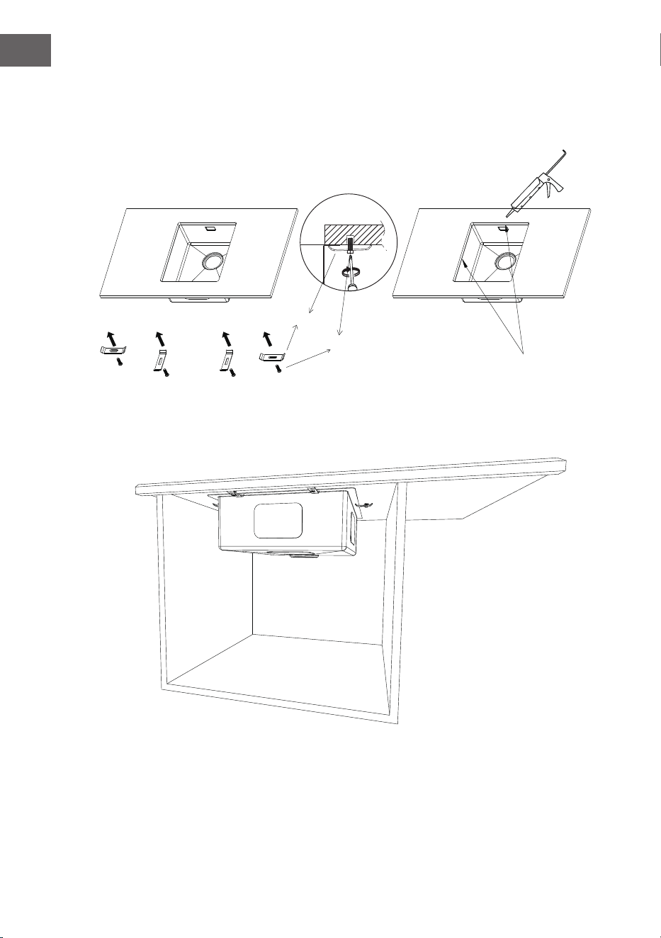
9. Installation der Küchenspüle mit Unterbauklammern
Befestigen Sie die Spüle am Ausschnitt auf der Rückseite der Arbeitsplatte, setzen Sie die
Schrauben und Klammern in den Dübel und ziehen Sie sie fest, um dann das Silikon zwischen
Arbeitsplatte und Spüle auf der Vorderseite aufzutragen.
B3
B2
Silikon auftragen
11
DE
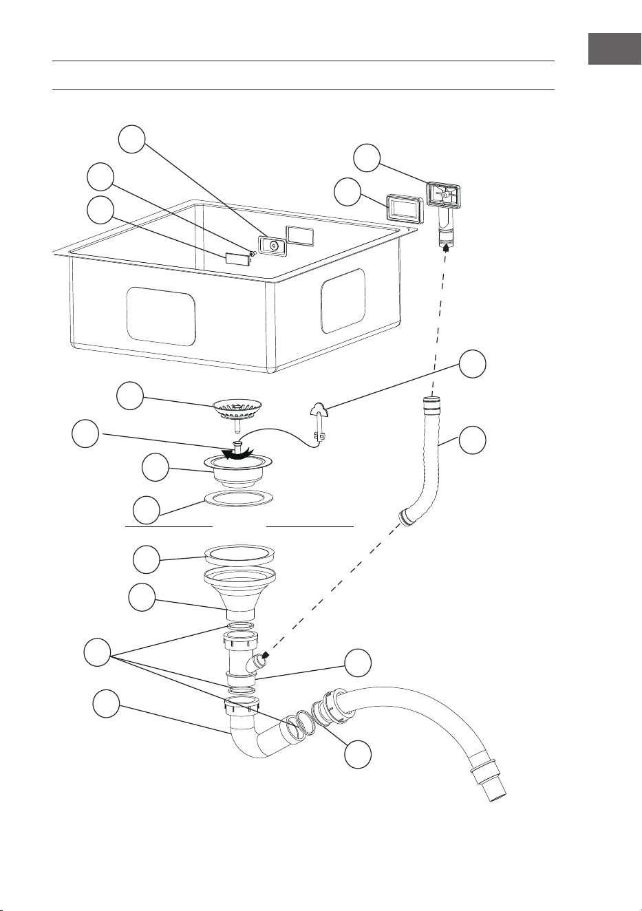
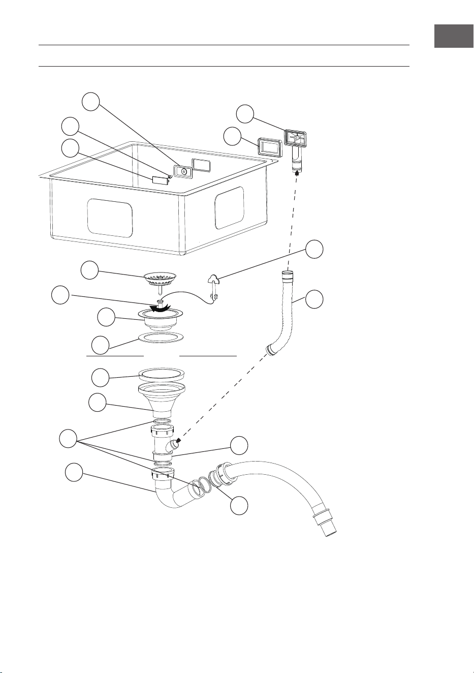
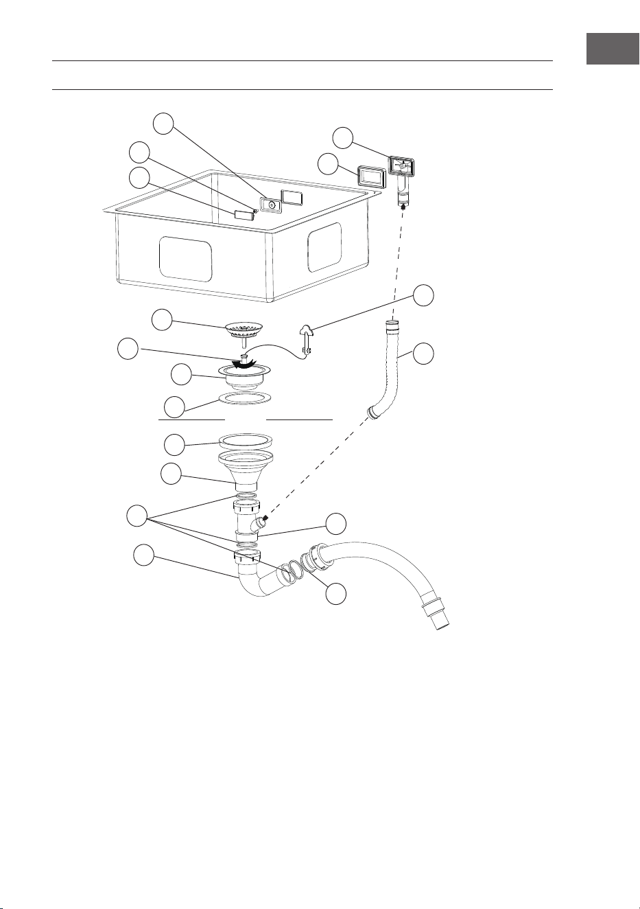
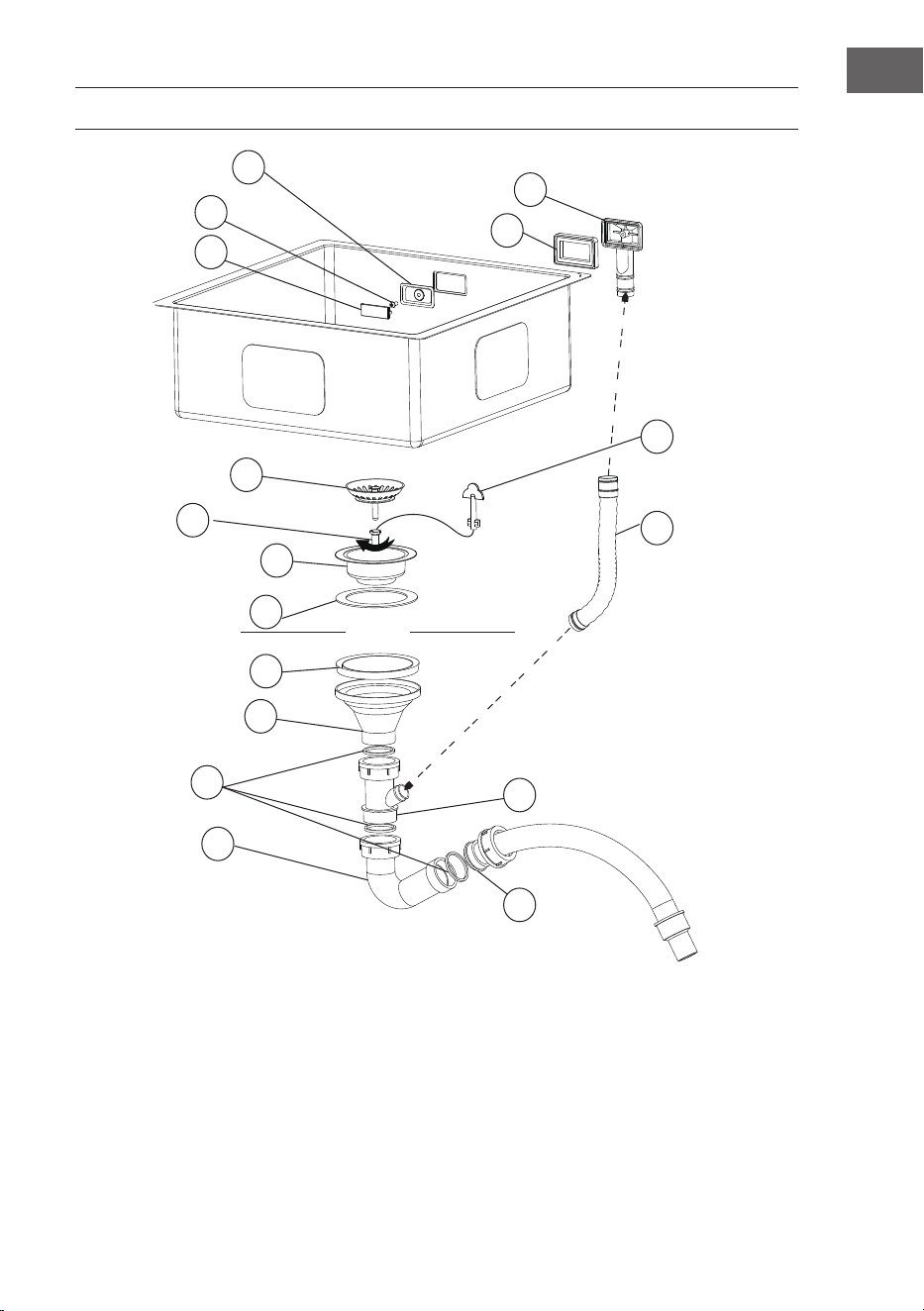
ABFLUSSSET INSTALLATION
sink
5
4
6
7
8
9
10
11
14
16
13
15
17
12
3
2
1
1 Überlaufabdeckung
2 Schraube A
3 Überlaufhalterung
4 Dichtungsring
5 Überlauf
6 Siebabdeckung
7 Schraube B
8 Edelstahlsiebboden
9 Dichtungsring des Siebs A
10 Dichtungsring des Siebs B
11 Kunststoffsiebboden
12 Schraubenanziehwerkzeug
13 Übergangsdichtungsring
14 Dreifachsteckverbindungen
15 Gebogenes Rohr
16 PVC-Stahldrahtrohr
17 Überussrohr

12
DE
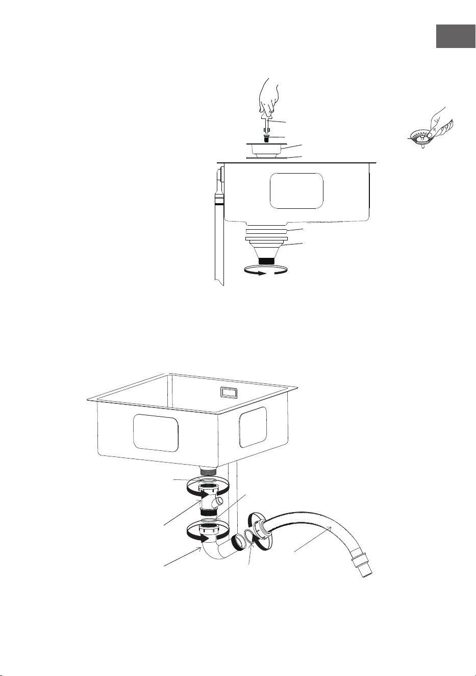
Installation der Überlaufgarnitur
Stecken Sie ④ auf ⑤, befestigen Sie ② in ③ und verbinden Sie sie anschließend durch die
Überlauföffnung.
Stellen Sie sicher, dass ② und ⑤ richtig verbunden sind und ziehen Sie ②
anschließend fest.
⑤
⑰
④
③
②
①
⑤ und ⑰ verbinden
① in ③ stecken, hineindrücken bis es fest
sitzt
13
DE
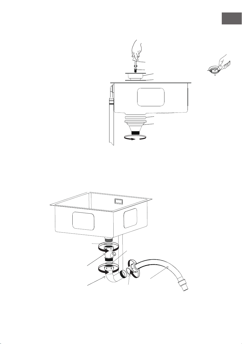
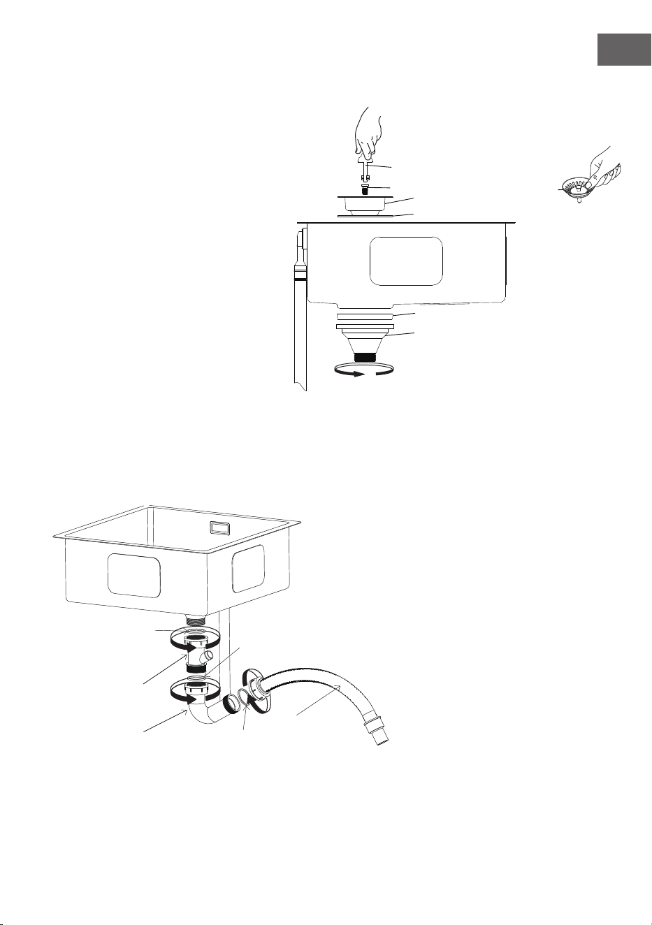
1. Nehmen Sie ⑥ heraus und verbinden
Sie die einzelnen Bestandteile des
Siebeinsatzes folgendermaßen:
Setzen Sie
⑦ in ⑧ ein und ziehen Sie
⑦ mit ⑫ fest. Setzen Sie ⑨ unter ⑧
ein und setzen Sie die Baugruppe in die
Abussöffnung der Spüle ein.
Setzen Sie
⑩ in ⑪ ein, verbinden Sie
beides mit der oberen Baugrupe und
ziehen Sie es fest.
Installation der Ablaufgarnitur
⑭
⑯
⑮
⑬A
⑬B
⑬C
⑫
⑧
⑨
⑩
⑪
⑥
⑦
2. Entnahme der Rohrleitungen
Setzen Sie den Dichtungsring
⑬A in ⑭ und verbinden Sie ⑭ anschließend mit ⑪ und ziehen Sie es fest.
Stecken Sie den Dichtungsring
⑬B in ⑮ und verbinden Sie anschließend ⑭ mit ⑮ und ziehen Sie es fest.
Stecken Sie den Dichtungsring
⑬C in ⑯,und verbinden Sie anschließend ⑯ mit ⑮ und ziehen Sie es fest.

14
DE
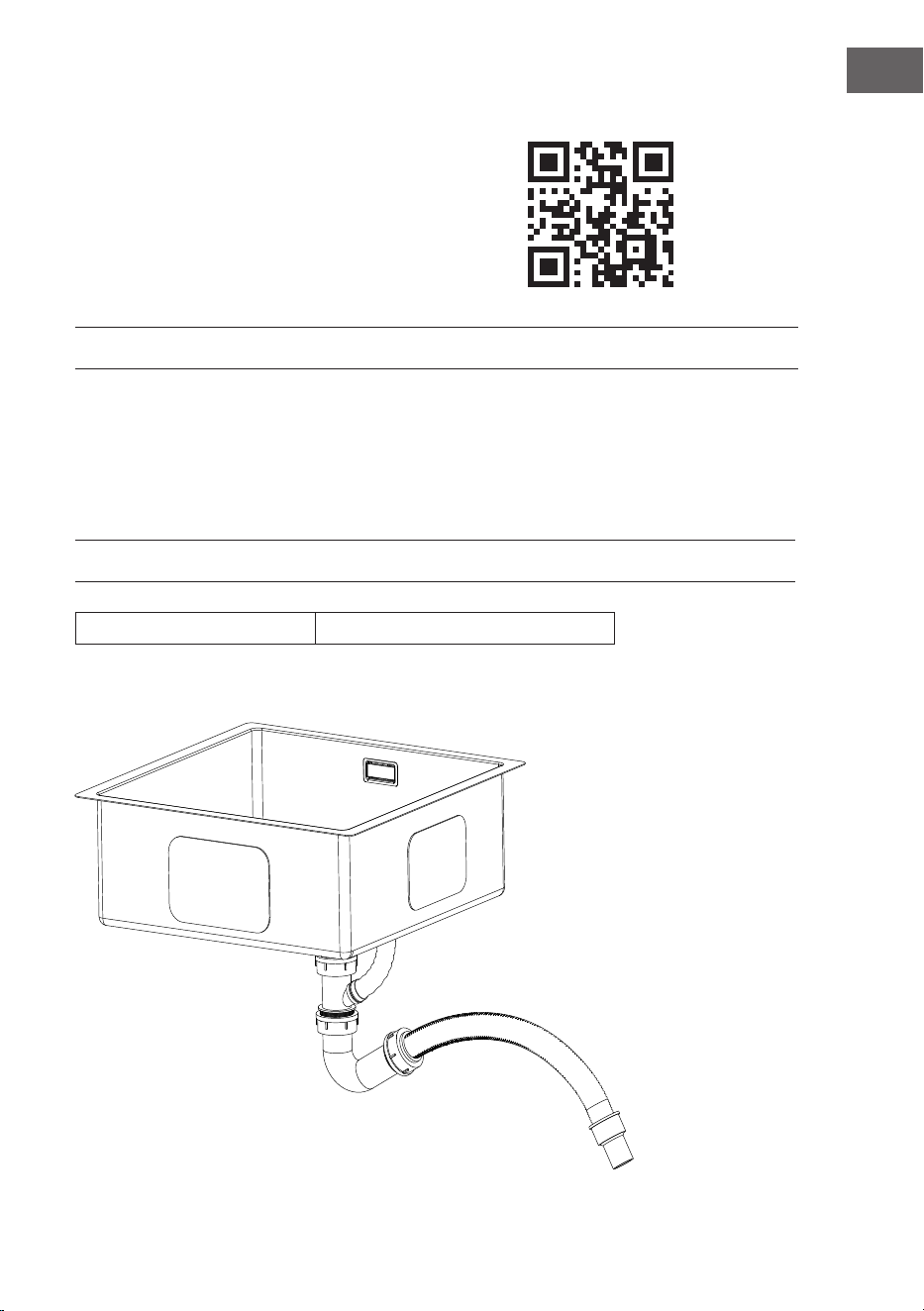
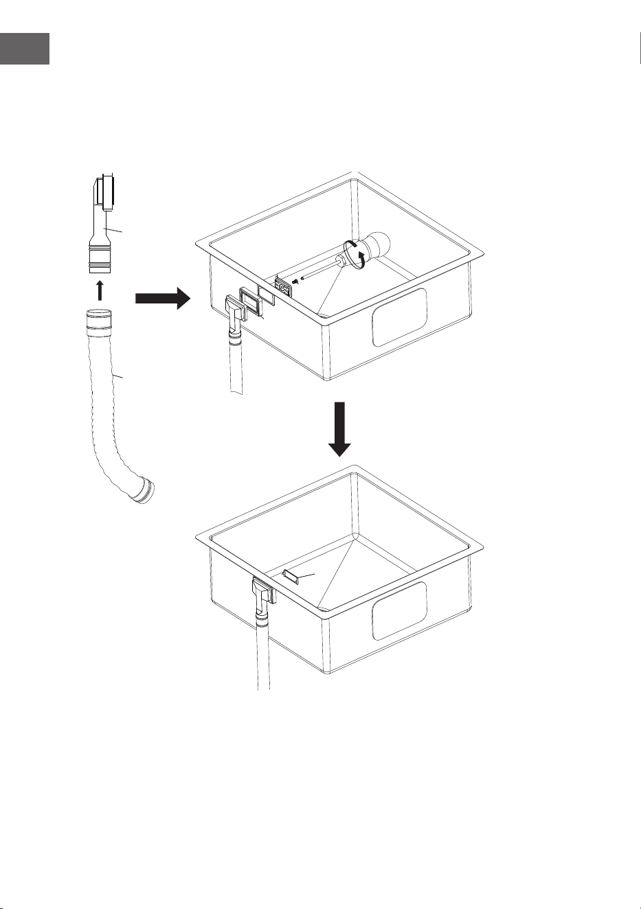
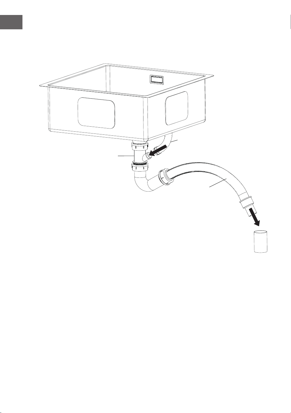
Abussset installieren
⑰
⑭
⑯
⑰ an ⑭ anschließen und ⑯ in das Abussrohr stecken.

15
DE
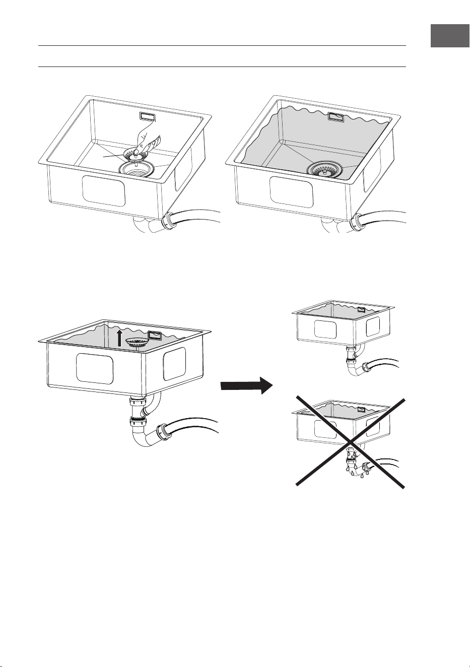
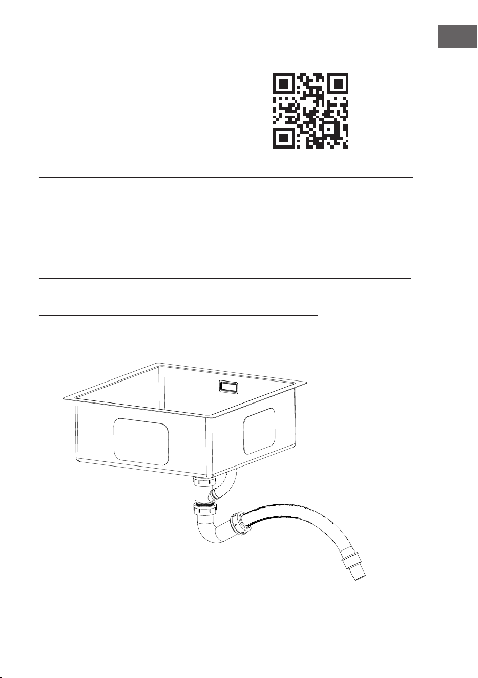
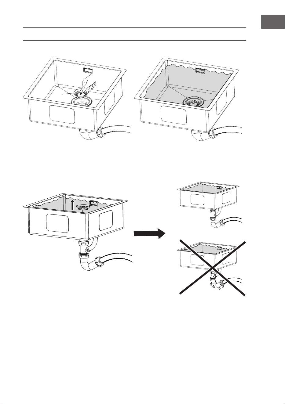
PRÜFEN DER DICHTUNGSLEISTUNG UND REINIGUNG
⑥
⑥ in ⑧ stecken.
Wenn
⑥ herausgenommen wird,
ießt das Wasser ab.
Befüllen Sie die Spüle bis zur
Überlauföffnung mit Wasser, so dass Wasser
aus dem Überlaufrohr kommt.
Wenn aus den Rohren kein Wasser tropft,
war die Installation erfolgreich.
Sollte Wasser aus den Rohren tropfen, überprüfen Sie, ob die Dichtungen richtig sitzen und passen
Sie diese gegebenenfalls an, um das Leck zu beseitigen.

16
DE
HERSTELLER
Chal-Tec GmbH, Wallstraße 16, 10179 Berlin, Deutschland (Germany).
Importeur für Großbritannien
Berlin Brands Group UK Limited
PO Box 42
272 Kensington High Street
London, W8 6ND
United Kingdom
17
EN
ARTICLE
Article number 10046017
CONTENTS
Contents 17
Parts List 18
Sink installtion for Undermouting 20
Drain set Installation 25
Check Sealing Performance and Clean 29
Manufacturer 30
Dear Customer,
Congratulations on purchasing this equipment. Please
read this manual carefully and take care of the following
hints on installation and use to avoid technical damages.
Any failure caused by ignoring the items and cautions
mentioned in the operation and installation instructions
are not covered by our warranty and any liability. Scan
the QR code to get access to the latest user manual and
more product information.
18
EN
PARTS LIST
x1 x1 x1 x1 x1
x1 x1 x1 x1 x1
x1 x1 x3 x1 x1
x1 x1 x6 x1
T
C
E
UT-OUT
MPLAT
E
1 2
3 4 5
6 7 8 9 10
11 12 13 14 15
16 17 18 19

19
EN
Tools
Pencil x1
Silicon x1
Screw driver x1 Scissor x1
Electric saw x1
Electric drill x1
⌀10 mm
⌀20 mm
⌀ 3 mm
Ruler x1
Shovel x1
20
EN
SINK INSTALLTION FOR UNDERMOUTING
No. Description Reference
Qty
A Kitchen Sink 1
B Undermout Clips
⑱
1
C Cutout Template
⑲
1
1. Cut the cut-out template along the wireframe with a
scissor
ALPMET TUO-TUC TUC ETETALPMET TUO-
2. Place the cut-out template on the counter and draw the wireframe on the counter with pencil
and ruler.
650mm
125mm
400mm
CUT-OUT TEMPLATE
Keep the template at.
21
EN
3. Drill 4 small holes with electric drills.First cut with small drill (⌀3), then cut with big drill (⌀20),
twice totally.
⌀3 mm ⌀20mm
4. Cut the counter along the cutting line
with electric saw.
5. Drill corresponding quantity holes according to the sink dimension at the back of counter with
electric drills,please refer to the distance between holes and lines.
⌀10 mm
back of counter
hole size:
⌀10 mm with depth 15 mm
22
EN
6. According to the following drawing, drill 6 ⌀10mm holes with a depth of 15 mm on the back of
the counter around the opening holes successively.
130mm
200mm
45mm
45mm
130mm
200mm
45mm
45mm
130mm
130mm
edge of the opening
7. Open the undermount clips,take out the anchors and install them to the holes under the
counter.
⑱
B1 anchor
B2 screw
B3 bracket
undermount clips

23
EN
back of counter
B1
8. Put a layer of silicon along side the cutting lines at the back of the counter and scrape the
silicon to be even and level.

24
EN
9. Install the kitchen sink with undermount clips.
Connect the sink to the cut-out hole at the back of the counter, put the screws and brackets into
the anchor and tighten, then to apply the silicon between counter and sink at the front.
B3
B2
Apply the silicon.
25
EN
DRAIN SET INSTALLATION
sink
5
4
6
7
8
9
10
11
14
16
13
15
17
12
3
2
1
1 Overow cover
2 ScrewA
3 Overow base
4 Sealing ring
5 Overow head
6 Strainer cover
7 Screw B
8 Strainer stainless steel base
9 Strainer sealing ring A
10 Strainer sealing ring B
11 Strainer plastic base
12 Screw tightening tool
13 Interface sealing ring
14 Three-way connectors
15 Bend pipe
16 PVC steel wire pipe
17 Overow pipe

26
EN
Install the overow set
Put ④ on ⑤,put ② in ③,then put them together through the overow hole , make sure ② is in ⑤,
then tighten
②.
⑤
⑰
④
③
②
①
Connect ⑤ and ⑰.
Put ① on ③, push it until stuck.
27
EN
1. Take out ⑥,dismiss to several parts as
below:
Put
⑦ in ⑧ and tighten ⑦ with ⑫,put
⑨ under ⑧ and put the whole assembly
into sink drain hole.
Put
⑩ in ⑪, then connect the above
assembly and tighten.
Install the strainer set
⑭
⑯
⑮
⑬A
⑬B
⑬C
⑫
⑧
⑨
⑩
⑪
⑥
⑦
2. Take out the pipes
Put sealing ring
⑬A in ⑭,then connect ⑭ with ⑪ and tighten.
Put sealing ring
⑬B in ⑮,then connect ⑭ with ⑮ and tighten.
Put sealing ring
⑬C in ⑯,then connect ⑯ with ⑮ and tighten.

28
EN
Install the waste pipe set
⑰
⑭
⑯
Connect ⑰ with ⑭ ,then put ⑯ into family waste pipe.
29
EN
CHECK SEALING PERFORMANCE AND CLEAN
⑥
Put ⑥ into ⑧.
Take out ⑥,the water will drain
Fill in water to overow hole.There is water
coming out from overow pipe.
There is no water coming out outside the
pipes. then it is successfully installed.
If there is water leakage, please check whether the fittings are tightened in this position to remove
water leakage.

30
EN
MANUFACTURER
Chal-Tec GmbH, Wallstraße 16, 10179 Berlin, Deutschland (Germany).
Importer for Great Britain
Berlin Brands Group UK Limited
PO Box 42
272 Kensington High Street
London, W8 6ND
United Kingdom

31
FR
ARTICLE
Numéro d'article 10046017
SOMMAIRE
Contenu de l'emballage 32
Installation encastrée 34
Installation du kit d'évacuation 39
Contrôle des performances des joints et nettoyage 43
Fabricant 44
Cher client, chère cliente,
Toutes nos félicitations pour l’acquisition de ce nouvel
appareil. Lisez attentivement les consignes suivantes
et suivez-les pour éviter d'éventuels dommages.
Nous déclinons toute responsabilité concernant les
dommages dus au non-respect des consignes et à la
mauvaise utilisation de l’appareil. Scannez le QR-Code
pour obtenir la dernière version du mode d'emploi ainsi
que d'autres informations concernant le produit

32
FR
CONTENU DE L'EMBALLAGE
x1 x1 x1 x1 x1
x1 x1 x1 x1 x1
x1 x1 x3 x1 x1
x1 x1 x6 x1
T
C
E
UT-OUT
MPLAT
E
1 2
3 4 5
6 7 8 9 10
11 12 13 14 15
16 17 18 19

33
FR
Outillage
Pencil x1
Silicon x1
Screw driver x1 Scissor x1
Electric saw x1
Electric drill x1
⌀10 mm
⌀20 mm
⌀ 3 mm
Ruler x1
Shovel x1
CrayonCrayon PerceusePerceuse RègleRègle
SiliconeSilicone Scie électriqueScie électrique SpatuleSpatule
TournevisTournevis CiseauxCiseaux
34
FR
INSTALLATION ENCASTRÉE
N° Description Réfé-
rence
Quan-
tité
A Évier de cuisine 1
B Bornes encastrées
⑱
1
C Gabarit de découpe
⑲
1
1. Découpez suivant le gabarit de découpe avec des
ciseaux.
ALPMET TUO-TUC TUC ETETALPMET TUO-
2. Placez le gabarit de découpe sur le plan de travail et utilisez un crayon et une règle pour tracer
le long des repères du gabarit.
650mm
125mm
400mm
CUT-OUT TEMPLATE
Placez le gabarit à plat.
Découpe
Gabarit
Découpe
Gabarit

35
FR
3. Percez quatre petits trous avec une perceuse électrique. Pré-percez d'abord les trous avec un
foret
⌀3 puis avec un foret ⌀20.
⌀3 mm ⌀20mm
4. Découpez le plan de travail le long du
marquage avec une scie électrique.
5. Percez le nombre approprié de trous selon les dimensions de l'évier à l'arrière du comptoir à
l'aide d'une perceuse électrique. Respectez l'espacement entre les trous et les lignes.
⌀10 mm
Dessous du plan
de travail
Taille du trou :
⌀ 10 mm avec une profondeur de 15 mm

36
FR
6. Comme le montre la figure ci-dessous, percez 6 trous de φ 10 mm de 15 mm de profondeur à
l'arrière du plan de travail autour de l'ouverture.
130mm
200mm
45mm
45mm
130mm
200mm
45mm
45mm
130mm
130mm
7. Ouvrez les supports de base, retirez les chevilles et insérez-les dans les trous sous le plan de
travail.
Dessous du plan de
travail
⑱
Cheville B1
Vis B2
Support B3
Supports de base

37
FR
Dessous du plan de travail
B1
8. Placez une couche de silicone à l'arrière du comptoir le long des lignes de coupe et lissez le
silicone pour qu'il soit uniforme et de niveau.

38
FR
9. Installation de l'évier à l'aide de supports encastrés
Fixez l'évier à la découpe à l'arrière du comptoir, insérez les vis et les supports dans l'ancrage
et serrez, puis appliquez le silicone entre le comptoir et l'évier à l'avant.
B3
B2
Appliquez du silicone
39
FR
INSTALLATION DU KIT D'ÉVACUATION
sink
5
4
6
7
8
9
10
11
14
16
13
15
17
12
3
2
1
1 Couvercle de trop-plein
2 Vis A
3 Support de trop-plein
4 bague d'étanchéité
5 Débordement
6 Couvercle de tamis
7 Vis B
8 Fond de tamis en acier inoxydable
9 bague d'étanchéité du tamis A
10 bague d'étanchéité du tamis B
11 Fond en plastique du tamis
12 Tournevis
13 Bague d'étanchéité de transition
14 Connecteurs triples
15 Tuyau coudé
16 Tuyau en fil d'acier et PVC
17 Tuyau de trop-plein
40
FR
Installation du trop-plein
Branchez ④ sur ⑤, fixez ② sur ③, puis connectez-les via l'ouverture de trop-plein.
Assurez-vous que ② et ⑤ sont correctement connectés, puis serrez ②.
⑤
⑰
④
③
②
①
Connectez ⑤ et ⑰
Insérez ① dans ③, appuyez jusqu'à ce
qu'il soit fermement en place

41
FR
1. Retirez ⑥ et raccordez les différents
composants du tamis comme suit :
Insérez
⑦ dans ⑧ et serrez ⑦ avec ⑫.
Insérez
⑨ sous ⑧ et insérez l'ensemble
dans l'ouverture de vidange de l'évier.
Insérez
⑩ dans ⑪, connectez les deux à
l'assemblage supérieur et serrez.
Installation du trop-plein
⑭
⑯
⑮
⑬A
⑬B
⑬C
⑫
⑧
⑨
⑩
⑪
⑥
⑦
2. Dépose des tuyaux
Placer la bague d'étanchéité
⑬A dans ⑭ puis connecter ⑭ à ⑪ et serrer. Dépose des tuyaux Placer la
bague d'étanchéité
⑬A dans ⑭ puis connecter ⑭ à ⑪ et serrer. Dépose des tuyaux Placer la bague
d'étanchéité
⑬A dans ⑭ puis connecter ⑭ à ⑪ et serrer.

42
FR
Installation du kit d'évacuation
⑰
⑭
⑯
Connectez ⑰ à ⑭ et insérez ⑯ dans le tuyau de vidange.

43
FR
CONTRÔLE DES PERFORMANCES DES JOINTS ET NETTOYAGE
⑥
Insérez ⑥ dans ⑧.
Lorsque vous retirez ⑥, l'eau
s'écoule.
Remplissez l'évier d'eau jusqu'à l'ouverture
de trop-plein afin que l'eau sorte du tuyau
de trop-plein.
S’il n’y a pas d’eau qui coule des tuyaux,
l’installation a réussi.
Si de l'eau s'écoule des canalisations, vérifiez que les joints sont bien en place et ajustez-les si
nécessaire pour éliminer la fuite.

44
FR
FABRICANT
Chal-Tec GmbH, Wallstraße 16, 10179 Berlin, Deutschland (Allemagne).
Importateur pour la Grande Bretagne
Berlin Brands GOIup UK Ltd
PO Box 42
272 Kensington High Street
London, W8 6ND
United Kingdom
45
IT
ARTICOLO
Numero articolo 10046017
INDICE
Volume di consegna 46
Installazione della sottostruttura 48
Installazione del set di scarico 53
Controllo delle prestazioni della guarnizione e pulizia 57
Produttore 58
Gentile cliente,
La ringraziamo per l'acquisto del dispositivo. La
preghiamo di leggere attentamente le seguenti
indicazioni e di seguirle per evitare eventuali danni. Non
ci assumiamo alcuna responsabilità per danni scaturiti
da una mancata osservanza delle avvertenze di sicurezza
e da un uso improprio del dispositivo. Scansionare il
seguente codice QR per accedere al manuale d’uso più
recente e ricevere informazioni sul prodotto.

46
IT
VOLUME DI CONSEGNA
x1 x1 x1 x1 x1
x1 x1 x1 x1 x1
x1 x1 x3 x1 x1
x1 x1 x6 x1
T
C
E
UT-OUT
MPLAT
E
1 2
3 4 5
6 7 8 9 10
11 12 13 14 15
16 17 18 19

47
IT
Attrezzi
Pencil x1
Silicon x1
Screw driver x1 Scissor x1
Electric saw x1
Electric drill x1
⌀10 mm
⌀20 mm
⌀ 3 mm
Ruler x1
Shovel x1
MatitaMatita TrapanoTrapano Metro pieghevoleMetro pieghevole
SiliconeSilicone Sega elettricaSega elettrica SpatolaSpatola
CacciaviteCacciavite ForbiceForbice
48
IT
INSTALLAZIONE DELLA SOTTOSTRUTTURA
N. Descrizione Riferi-
mento
Quan-
tità
A Lavandino da cucina 1
B Morsetti per l'incasso
⑱
1
C Sagoma
⑲
1
1. Tagliare la sagoma con una forbice seguendo la linea.
ALPMET TUO-TUC TUC ETETALPMET TUO-
2. Poggiare la sagoma sul piano di lavoro e seguire la linea con una matita e un metro pieghevole.
650mm
125mm
400mm
CUT-OUT TEMPLATE
Poggiare la sagoma.
Sagoma per il
taglio
.
Sagoma per il taglio
.

49
IT
3. Realizzare 4 piccoli fori con un trapano elettrico. Realizzare prima i fori con una punta di ⌀3 e
poi con una di
⌀20.
⌀3 mm ⌀20mm
4. Tagliare il piano di lavoro con una sega
elettrica seguendo la forma disegnata
utilizzando la sagoma.
5. Realizzare il numero di fori relativo alle dimensioni del lavandino sul retro del piano di lavoro
con un trapano elettrico. Fare attenzione alla distanza tra fori e linee.
⌀10 mm
Lato inferiore
del piano di
lavoro
Dimensione dei fori:
⌀
10 mm con
15 mm di profondità
50
IT
6. Seguendo l'immagine seguente, realizzare 6 fori da φ10mm con una profondità di 15 mm sul
retro del piano di lavoro intorno all'apertura che è stata tagliata in precedenza.
130mm
200mm
45mm
45mm
130mm
200mm
45mm
45mm
130mm
130mm
7. Aprire i morsetti per l'incasso, tirare fuori i tasselli e inserirli nei fori sotto il piano di lavoro.
Bordo del piano di
lavoro
⑱
B1 Tassello
B2 Vite
B3 Supporto
Morsetti per l'incasso

51
IT
Lato inferiore del piano di lavoro
B1
8. Applicare uno strato di silicone lungo le linee di taglio sul retro del piano di lavoro e stenderlo,
in modo che risulti piatto e omogeneo.

52
IT
9. Installazione del lavandino con morsetti per l'incasso
Fissare il lavandino all'apertura sul retro del piano di lavoro, inserire le viti e i morsetti nei
tasselli e stringere saldamente. Applicare poi il silicone tra il piano di lavoro e il lavandino sul
lato anteriore.
B3
B2
Applicare il silicone
53
IT
INSTALLAZIONE DEL SET DI SCARICO
sink
5
4
6
7
8
9
10
11
14
16
13
15
17
12
3
2
1
1 Copertura di traboccamento
2 Vite A
3 Supporto di traboccamento
4 Guarnizione ad anello
5 Traboccamento
6 Copertura a setaccio
7 Vite B
8 Fondo del setaccio in acciaio inox
9 Guarnizione ad anello del setaccio A
10 Guarnizione ad anello del setaccio B
11 Fondo del setaccio di plastica
12 Attrezzo per stringere le viti
13 Guarnizione ad anello di transizione
14 Connettori tripli
15 Tubo curvo
16 Tubo in cavo d'acciaio e PVC
17 Tubo di traboccamento

54
IT
Installazione del set di traboccamento
Inserire ④ su ⑤, fissare ② in ③ e collegarli poi attraverso l'apertura di traboccamento.
Assicurarsi che ② e ⑤ siano collegati correttamente e poi stringere ② saldamente.
⑤
⑰
④
③
②
①
Collegare ⑤ e ⑰.
Inserire ① in ③ e premere fino al
fissaggio.
55
IT
1. Estrarre ⑥ e collegare i singoli pezzi
dell'attacco a setaccio in questo modo:
Inserire
⑦ in ⑧ e stringere ⑦
saldamente con
⑫. Posizionare ⑨ sotto
⑧ e inserire il gruppo nell'apertura di
scarico del lavandino.
Inserire
⑩ in ⑪, collegarli entrambi
con il gruppo superiore e stringere
saldamente.
Installazione del set di scarico
⑭
⑯
⑮
⑬A
⑬B
⑬C
⑫
⑧
⑨
⑩
⑪
⑥
⑦
2. Rimozione dei condotti
Inserire la guarnizione ad anello
⑬A in ⑭, collegare poi ⑭ con ⑪ e stringere saldamente. Inserire la
guarnizione ad anello
⑬B in ⑮, collegare poi ⑭ con ⑮ e stringere saldamente. Inserire la guarnizione ad
anello
⑬C in ⑯, collegare poi ⑯ con ⑮ e stringere saldamente.
56
IT
Installare il set di scarico
⑰
⑭
⑯
Collegare ⑰ a ⑭ e inserire ⑯ nel tubo di scarico.

57
IT
CONTROLLO DELLE PRESTAZIONI DELLA GUARNIZIONE E
PULIZIA
⑥
Inserire ⑥ in ⑧.
Se si rimuove
⑥, l'acqua viene
scaricata.
Riempire il lavandino d'acqua fino
all'apertura di traboccamento, in modo che
l'acqua esca dal tubo di traboccamento.
Se dai tubi non gocciola acqua, l'installazione
è stata realizzata correttamente.
Se gocciola acqua dai tubi, controllare se le guarnizioni sono posizionate correttamente e, se
necessario, regolarle in modo da eliminare la perdita.

58
IT
PRODUTTORE
Chal-Tec GmbH, Wallstraße 16, 10179, Berlino (Germania)
Importatore per la Gran Bretagna
Berlin Brands Group UK Limited
PO Box 42
272 Kensington High Street
London, W8 6ND
United Kingdom

59
ES
ARTÍCULO
Número del artículo 10046017
ÍNDICE
Contenido del envío 60
Instalación de la subestructura 62
Instalación del kit de desagüe 67
Comprobación de la estanqueidad y limpieza 71
Fabricante 72
Estimado cliente:
Le felicitamos por la adquisición de este producto. Lea
atentamente el siguiente manual y siga cuidadosamente
las instrucciones de uso con el fin de evitar posibles
daños. La empresa no se hace responsable por los daños
causados por el incumplimiento de las instrucciones y
el uso indebido. Escanee el siguiente código QR para
obtener acceso al manual de usuario más reciente y otra
información sobre el producto.

60
ES
CONTENIDO DEL ENVÍO
x1 x1 x1 x1 x1
x1 x1 x1 x1 x1
x1 x1 x3 x1 x1
x1 x1 x6 x1
T
C
E
UT-OUT
MPLAT
E
1 2
3 4 5
6 7 8 9 10
11 12 13 14 15
16 17 18 19

61
ES
Herramientas
Pencil x1
Silicon x1
Screw driver x1 Scissor x1
Electric saw x1
Electric drill x1
⌀10 mm
⌀20 mm
⌀ 3 mm
Ruler x1
Shovel x1
LápizLápiz BrocaBroca Regla plegableRegla plegable
SiliconaSilicona Sierra eléctricaSierra eléctrica EspátulaEspátula
DestornilladorDestornillador TijerasTijeras
62
ES
INSTALACIÓN DE LA SUBESTRUCTURA
Núm. Descripción Refe-
rencia
Can-
tidad
A Fregadero 1
B
Terminales
empotrados
⑱
1
C Plantilla de corte
⑲
1
1. Recorte la plantilla de corte por la marca con unas
tijeras.
ALPMET TUO-TUC TUC ETETALPMET TUO-
2. Coloque la plantilla de corte sobre la encimera y trace a lo largo de las marcas de la plantilla
utilizando un lápiz y una regla de plegado.
650mm
125mm
400mm
CUT-OUT TEMPLATE
Coloque la plantilla en posición
horizontal.
Recorte
Plantilla
Recorte
Plantilla
63
ES
3. Taladre 4 agujeros pequeños con un taladro eléctrico. Pretaladre primero los agujeros con un
accesorio con
⌀3 y después con un accesorio con ⌀20.
⌀3 mm ⌀20mm
4. Recorte la encimera a lo largo de la
marca utilizando una sierra eléctrica.
5. Taladre con un taladro eléctrico el número de orificios adecuado a las dimensiones del
fregadero en la parte posterior de la encimera. Observe la distancia entre los orificios y las
líneas.
⌀10 mm
Parte inferior de
la encimera
Tamaño del agujero:
⌀10 mm con 15 mm
de profundidad

64
ES
6. Taladre 6 agujeros de φ10 mm con una profundidad de 15 mm en la parte posterior de la
encimera alrededor de la abertura como se muestra en la siguiente ilustración.
130mm
200mm
45mm
45mm
130mm
200mm
45mm
45mm
130mm
130mm
7. Abra las abrazaderas de la subestructura, extraiga los tacos e introdúzcalos en los orificios
situados debajo de la encimera.
Parte inferior de
la encimera
⑱
Taco B1
Tornillo B2
Soporte B3
Abrazaderas de la
subestructura
65
ES
Parte inferior de la encimera
B1
8. Coloque una capa de silicona a lo largo de las líneas de corte en la parte posterior de la
encimera y extienda la silicona de forma que quede uniforme y lisa.
66
ES
9. Instalación del fregadero de cocina con soportes de montaje bajo encimera
Fijar el fregadero en el recorte de la parte posterior de la encimera, insertar los tornillos y los
soportes en la espiga y apretarlos, después aplicar la silicona entre la encimera y el fregadero
en la parte frontal.
B3
B2
Aplicar silicona

67
ES
INSTALACIÓN DEL KIT DE DESAGÜE
sink
5
4
6
7
8
9
10
11
14
16
13
15
17
12
3
2
1
1 Tapa del rebosadero
2 Tornillo A
3 Soporte del rebosadero
4 Junta de estanqueidad
5 Desbordamiento
6 Cubierta de malla
7 Tornillo B
8 Fondo del filtro de acero inoxidable
9 Anillo de estanqueidad del filtro A
10 Anillo de estanqueidad del filtro B
11 Fondo de filtro de plástico
12 Herramienta de apriete de tornillos
13 Junta de paso
14 Conectores triples
15 Tubo doblado
16 Tubo de alambre de acero PVC
17 Tubería sobrante

68
ES
Instalación del kit de desagüe
Empuje ④ sobre ⑤, fije ② en ③ y luego conéctelos a través de la abertura del
rebosadero.
Asegúrese de que ② y ⑤ están conectados correctamente y luego apriete ②.
⑤
⑰
④
③
②
①
Conecte ⑤ y ⑰.
Inserte ① en ③, presione hasta que
quede firmemente asentado

69
ES
1. Retire ⑥ y conecte los componentes
individuales del conjunto de desagüe
como se indica a continuación:
Inserte
⑦ en ⑧ y apriete ⑦ con ⑫.
Inserte
⑨ debajo de ⑧ e introduzca el
conjunto en la abertura de desagüe del
fregadero.
Inserte
⑩ en ⑪, conecte ambos al
conjunto superior y apriete.
Instalación del kit de desagüe
⑭
⑯
⑮
⑬A
⑬B
⑬C
⑫
⑧
⑨
⑩
⑪
⑥
⑦
2. Extracción de la tubería
Inserte el anillo de sellado
⑬A en ⑭ y, a continuación, conecte ⑭ a ⑪ y apriételo. Inserte el anillo
de sellado
⑬B en ⑮ y luego conecte ⑭ a ⑮ y apriételo. Inserte el anillo de sellado ⑬C en ⑯ y, a
continuación, conecte
⑯ a ⑮ y apriete.

70
ES
Instalación del kit de desagüe
⑰
⑭
⑯
Conectar ⑰ a ⑭ e insertar ⑯ en el tubo de desagüe.
71
ES
COMPROBACIÓN DE LA ESTANQUEIDAD Y LIMPIEZA
⑥
Inserte ⑥ en ⑧.
Cuando se retira ⑥, el agua sale.
Llene el fregadero con agua hasta la
abertura de rebose para que el agua salga
por el tubo de rebose.
Si no gotea agua de las tuberías, la
instalación se ha realizado correctamente.
Si gotea agua de las tuberías, compruebe que las juntas están correctamente asentadas y ajústelas
si es necesario para eliminar la fuga.

72
ES
FABRICANTE
Chal-Tec GmbH, Wallstraße 16, 10179 Berlín, Alemania.
Importador para el Reino Unido:
Berlin Brands Group UK Limited
PO Box 42
272 Kensington High Street
London, W8 6ND
Reino Unido