
1
GV-Cloud Bridge Pro
Contents
Topology Diagrams ...................................................................................................... 3
1 Compatible Products .............................................................................................. 4
2 Packing List ............................................................................................................ 4
3 Overview .................................................................................................................. 5
4 GV-Cloud VMS Licenses......................................................................................... 6
5 Connecting to PC .................................................................................................... 9
6 Installing the SSD ................................................................................................... 9
7 Accessing GV-Cloud Bridge Pro ........................................................................... 11
7.1 Assigning a Static IP Address ........................................................................12
7.2 Configuring the DDNS Domain Name ............................................................13
8 Operation Mode .....................................................................................................15
9 Live View ................................................................................................................16
10 General Settings ..................................................................................................18
10.1 Connecting to IP Cameras ...........................................................................18
10.2 Configuring Input / Output Settings ..............................................................20
10.3 Connecting to I/O Boxes ..............................................................................23
10.4 Connecting to IP Speakers ...........................................................................24
11 Service Settings ...................................................................................................26
11.1 Connecting to GV-Cloud VMS ......................................................................26
11.2 Connecting to GV-Cloud Access Control ......................................................29
11.3 Connecting to GV-Center V2 / Dispatch Server ............................................35
11.4 Connecting to GV-Recording Server / Video Gateway ..................................37
11.5 Connecting to GV-Relay (GV-Eye App) ........................................................38
11.6 Connecting to GV-CVW ................................................................................40
11.7 Live Broadcasting .........................................................................................42
12 System Settings ...................................................................................................45
12.1 Basic ............................................................................................................45
12.2 Account and Authority ..................................................................................46
12.3 Network Settings ..........................................................................................47
12.4 Date and Time ..............................................................................................47
12.5 RS-485.........................................................................................................48
12.6 Maintenance ................................................................................................49
13 Storage .................................................................................................................50

2
14 VPN .......................................................................................................................51
15 People and Vehicle Detection (PVD) ...................................................................57
16 Firmware Upgrade ...............................................................................................59
3
Topology Diagrams
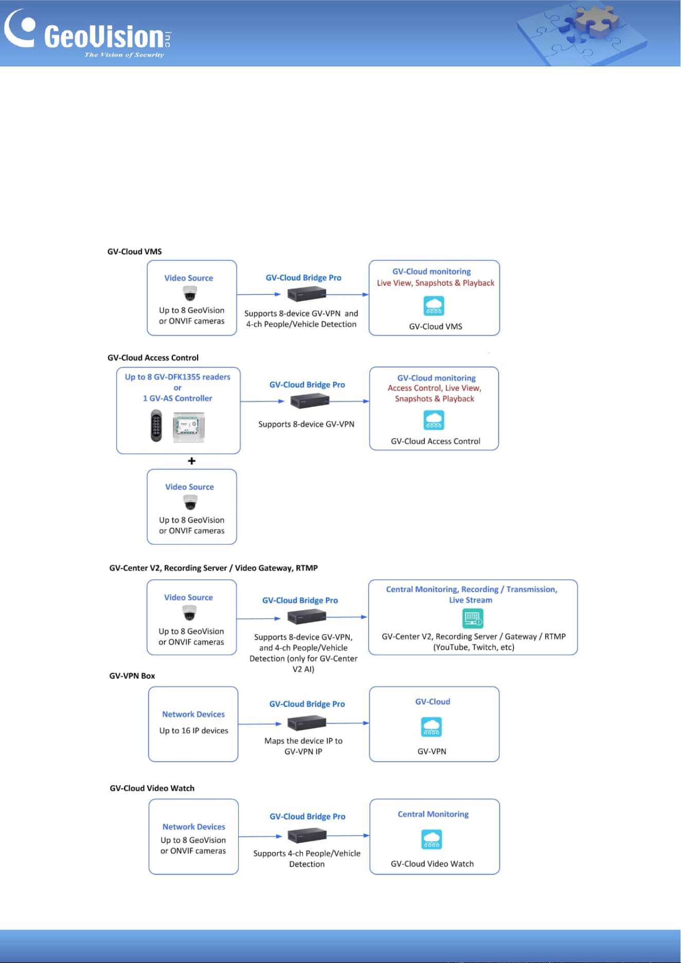
GV-Cloud Bridge Pro supports five major operation modes between cameras, readers,
controllers, IP devices, and GeoVision software: GV-Cloud VMS, GV-Cloud Access Control,
GV-Center V2 / Recording Server / Video Gateway / RTMP, GV-VPN Box, and GV-Cloud
Video Watch. Only one of the operation modes can be enabled at once.
4
1 Compatible Products
• Camera: GV-IP cameras or ONVIF cameras
⚫ Software:
。 GV-Center V2 V18.4.1 or later
。 GV-Recording Server / Video Gateway (coming soon)
。 GV-Dispatch Server V18.2.0A or later
。 GV-VPN V1.1.0 or later
⚫ GV-Cloud VMS (cloud-based software): V1.2.1 or later
⚫ GV-Cloud Access Control (cloud-based software): V1.1.0 or later
。 GV-AS Controller (controller): GV-AS210 / 2110 / 2120, GV-AS410 / 4110 / 4111
firmware V2.60 or later
。 GV-DFK1355 (reader)
• Mobile App: GV-Eye V3.3.0 or later
• GV-Cloud Video Watch (central monitoring center): (coming soon)
2 Packing List
• GV-Cloud Bridge Pro
• Terminal Block
• Download Guide
Note:
1. To allow GV-IP Cameras without GV-Center V2 settings to connect to GV-Center V2, use
GV-Cloud Bridge Pro.
2. To access 3rd party IP cameras using the GV-Eye app, use GV-Cloud Bridge Pro.
3. To allow 3rd party IP cameras to establish passive connections to GV-Recording Server /
Video Gateway without port forwarding, use GV-Cloud Bridge Pro.
4. When working with GV-Center V2,
• GV-Center V2 V18.4.1 and GV-Dispatch Server V18.2.0A do not support AI and
PVD events.
• GV-Center V2 AI version supports AI and PVD events.
5
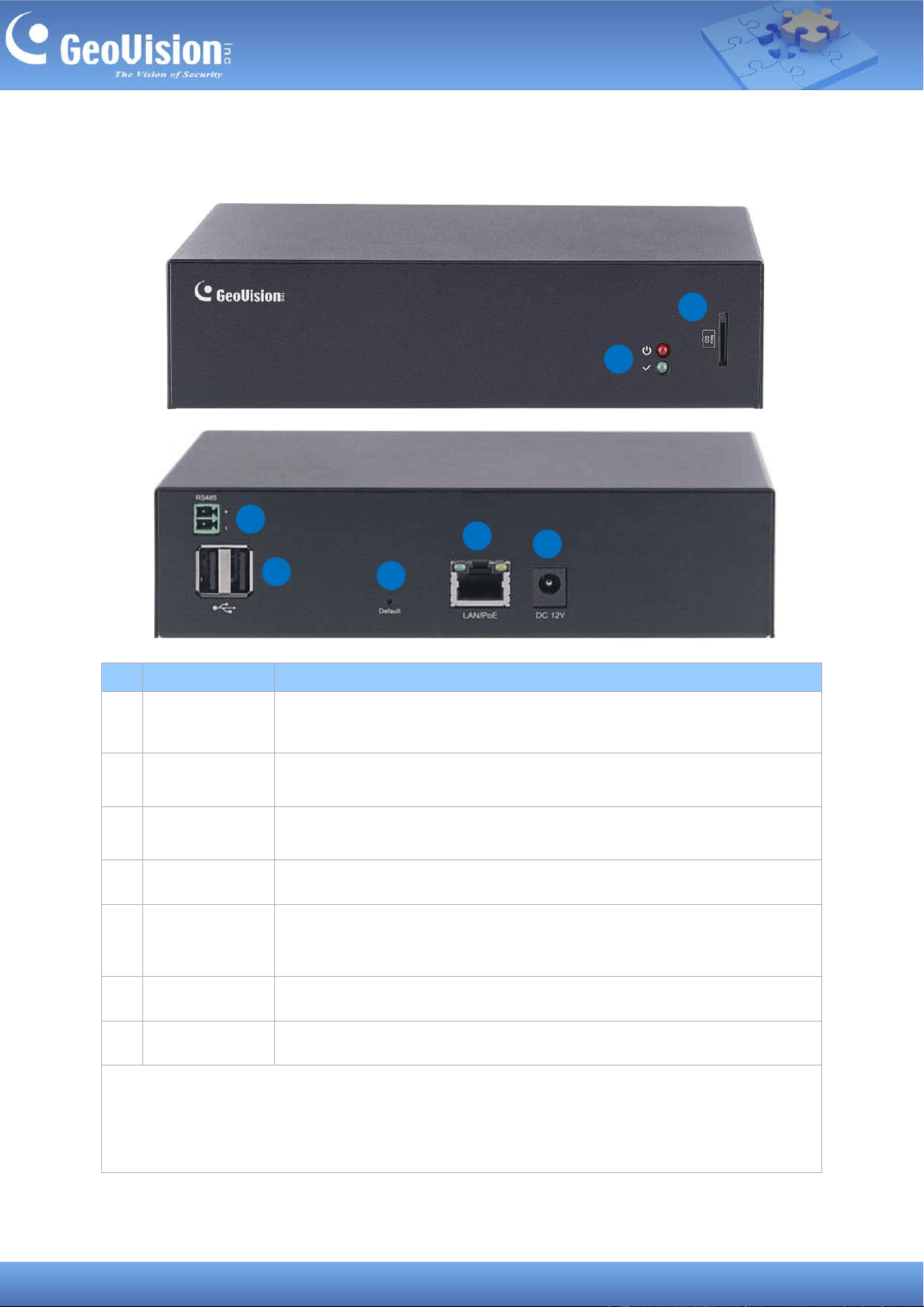
3 Overview
3
4
5
6
7
1
2
No
Name
Description
1.
LED
The Red LED indicates the power is supplied.
The Green LED indicates a network is connected.
2.
Memory Card
Insert a Micro SD card (SDHC / SDXC / UHS-I, Class 10, Linux ext4
format). To format a SD card, see 13 Storage.
3.
RS-485
Connect to up to 8 GV-DFK1355 readers via the RS-485 interface. See
12.5 RS-485 and 11.2 Connecting to GV-Cloud Access Control.
4.
USB
Not functional
5.
Default
Hold and press the button for 10 ~ 15 seconds to load the default. To
restore to default settings using the Web interface, see 12.6
Maintenance.
6.
LAN/PoE
Connect to a network or power over Ethernet.
7.
DC 12V
Connect to power.
IMPORTANT: The device can only accept one power source, either a PoE power supply or a
DC power adapter. Connecting two power sources simultaneously can damage the device.
Note: The device also supports SSD storage. To install a SSD, see 6 Installing a SSD.
6
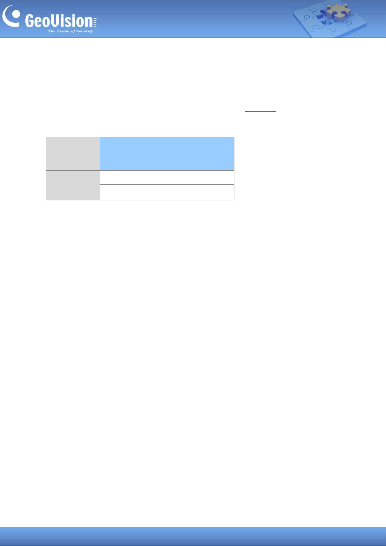
4 GV-Cloud VMS Licenses
To use GV-Cloud Bridge Pro with GV-Cloud VMS, select the license that best meets your
surveillance requirements. GV-Cloud VMS provides three license options: Basic, Standard,
and Premium. For details on GV-Cloud VMS licenses, see the datasheet.
Basic and Standard Licenses
Camera
Resolution
Storage
Type
Basic
Standard
8 / 5 / 4 / 2 / 1
MP
SSD
8 CH
SD Card
4 CH
7
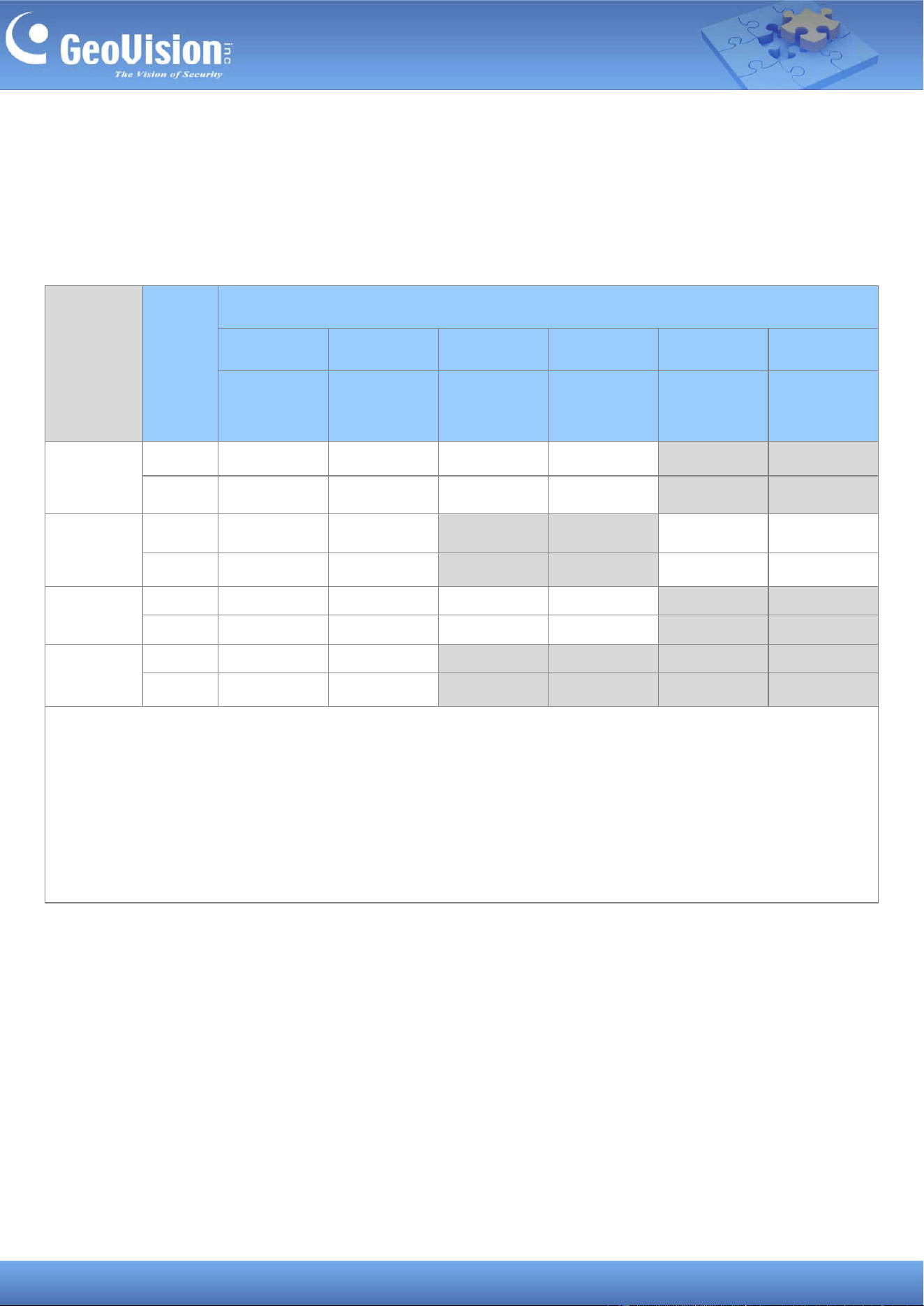
Premium License
As you integrate GV-Cloud Bridge Pro and GV-Cloud VMS, the following GV-Cloud VMS
premium licenses are available based on the resolution of recordings to be uploaded to
GV-Cloud VMS (SD, 720p, 2M, 2M / 30F, 4M, 4M / 30F) and each license specifies the frame
rate and bitrate limit.
Camera
Resolution
Storage
Type
Maximum Channels supported by GV-Cloud VMS Premium Licenses
SD (640*480)
720p
2M
2M / 30F
4M
1
4M / 30F
1
30 FPS +
512 Kbps
30 FPS +
1 Mbps
15 FPS +
1 Mbps
30 FPS +
2 Mbps
15 FPS +
2 Mbps
30 FPS +
3 Mbps
8 MP
SSD
8 CH
8 CH
8 CH
8 CH
8 CH
2
8 CH
2
SD Card
4 CH
4 CH
4 CH
4 CH
4 CH
2
4 CH
2
5 / 4 MP
SSD
8 CH
8 CH
8 CH
2
8 CH
2
8 CH
1
8 CH
1
SD Card
4 CH
4 CH
4 CH
2
4 CH
2
4 CH
1
4 CH
1
2 MP
SSD
8 CH
8 CH
8 CH
8 CH
8 CH
3
8 CH
3
SD Card
4 CH
4 CH
4 CH
4 CH
4 CH
3
4 CH
3
1 MP
SSD
8 CH
8 CH
8 CH
3
8 CH
3
8 CH
3
8 CH
3
SD Card
4 CH
4 CH
4 CH
3
4 CH
3
4 CH
3
4 CH
3
Note:
1. The 4MP GV-Cloud Premium license also support 5MP resolution. Recordings from 5MP cameras will be uploaded and
stored in 5MP quality on GV-Cloud VMS.
2. Users must manually lower the camera’s resolution to match the licensed resolution; otherwise, the sub stream
resolution will be applied.
3. Higher-resolution Premium licenses can be applied to cameras with lower resolution, but this is not recommended for
optimal license utilization.
8
When GV-Cloud Bridge Pro is connected to GV-Cloud VMS, the camera's resolution is
constantly monitored and immediately adjusted when it exceeds the limits of the applied
licenses by resolution (SD / 720p / 2 MP / 4 MP).
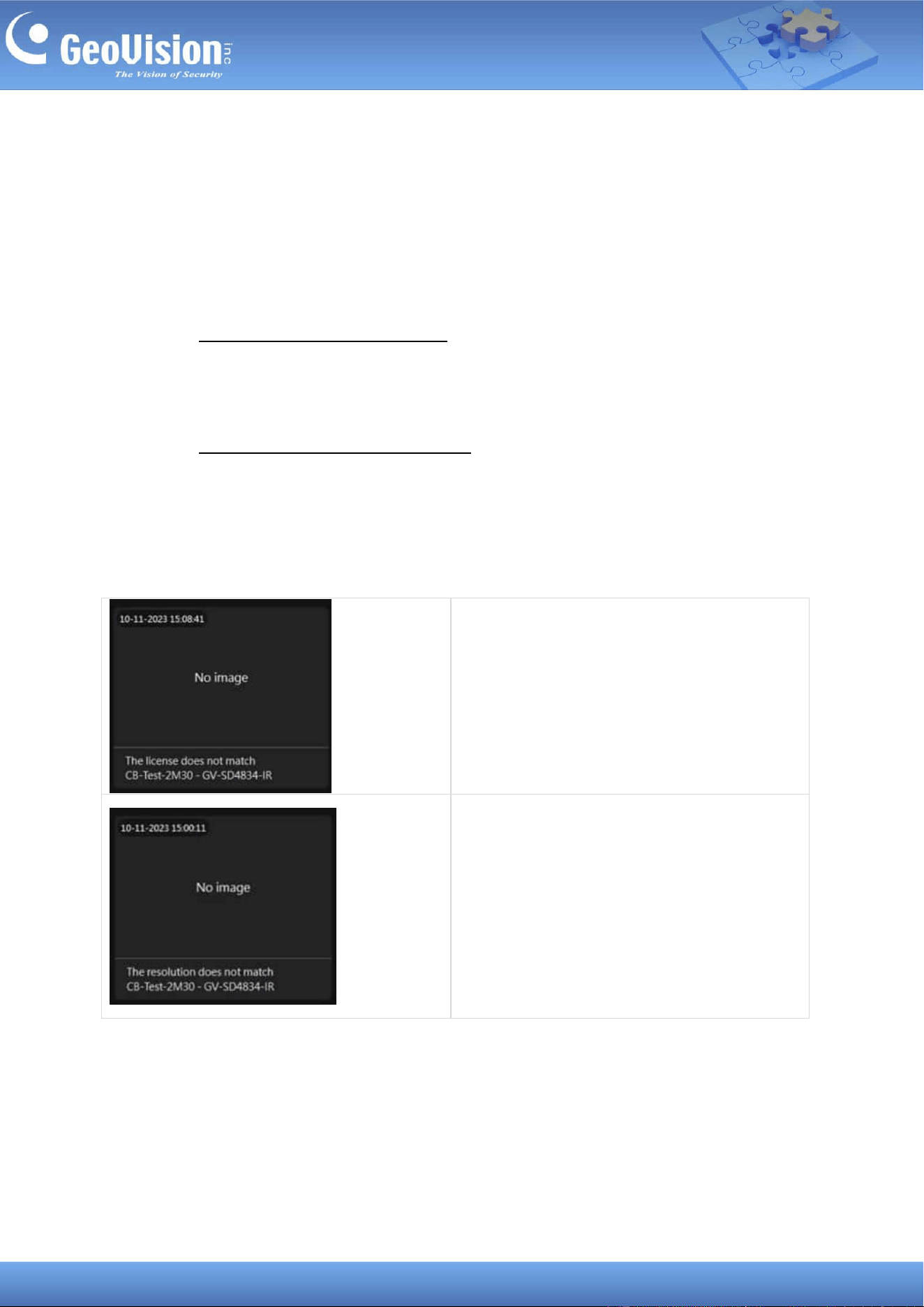
When the camera’s main stream / sub stream resolution does not match the applied
GV-Cloud VMS license, the following conditions will occur:
1. When the main stream or sub stream resolution is lower than the applied license:
(1) The recordings will be uploaded to GV-Cloud VMS using the closest resolution; (2)
The Resolution does not match event will be included in GV-Cloud VMS event log; (3)
An alert message will be sent via e-mail.
2. When both main stream and sub stream resolution exceeds the applied license: (1)
The recordings will only be saved in the SSD or the memory card in GV-Cloud Bridge Pro
based on the main stream resolution; (2) The License does not match event will be
included in GV-Cloud VMS event log; (3) An alert message will be sent via e-mail.
GV-Cloud VMS event logs of License not matched and Resolution not matched
The License does not match CB.
The Resolution does not match CB.
9
5 Connecting to PC
There are two options for powering and connecting GV-Cloud Bridge Pro to a computer. Only
one of the two ways can be utilized at once.
1. Connect an optional GV-PA301 PoE Adapter to the PC via the LAN port (see No. 7, 3
Overview) to receive power over Ethernet.
2. Use an optional power adapter to power on the device. Connect to network via the LAN
port (No. 7, 3 Overview).
6 Installing the SSD
To install an SSD in GV-Cloud Bridge Pro using the optional SSD mounting kit, follow the
steps below.
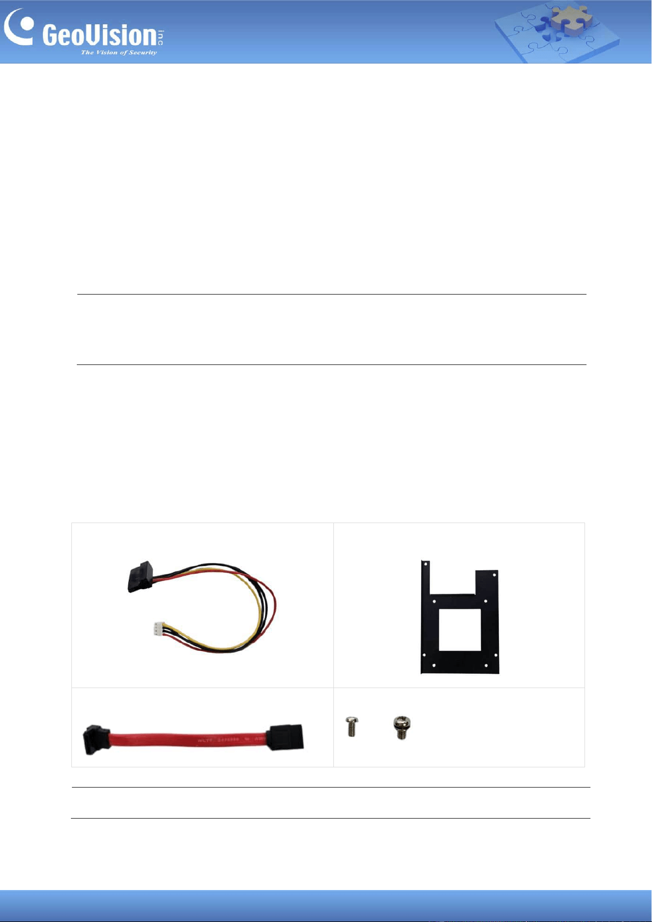
The SSD mounting kit
1. SATA Power Cable
2. Mounting Plate
3. SATA Data Cable
4. Screws
x 4, x 4
Note: The optional SSD mounting kit is required to install the SSD drive.
IMPORTANT: GV-Cloud Bridge Pro can only accept one power source, either a PoE power
supply or a DC power adapter. Connecting two power sources simultaneously can damage
the device.
10
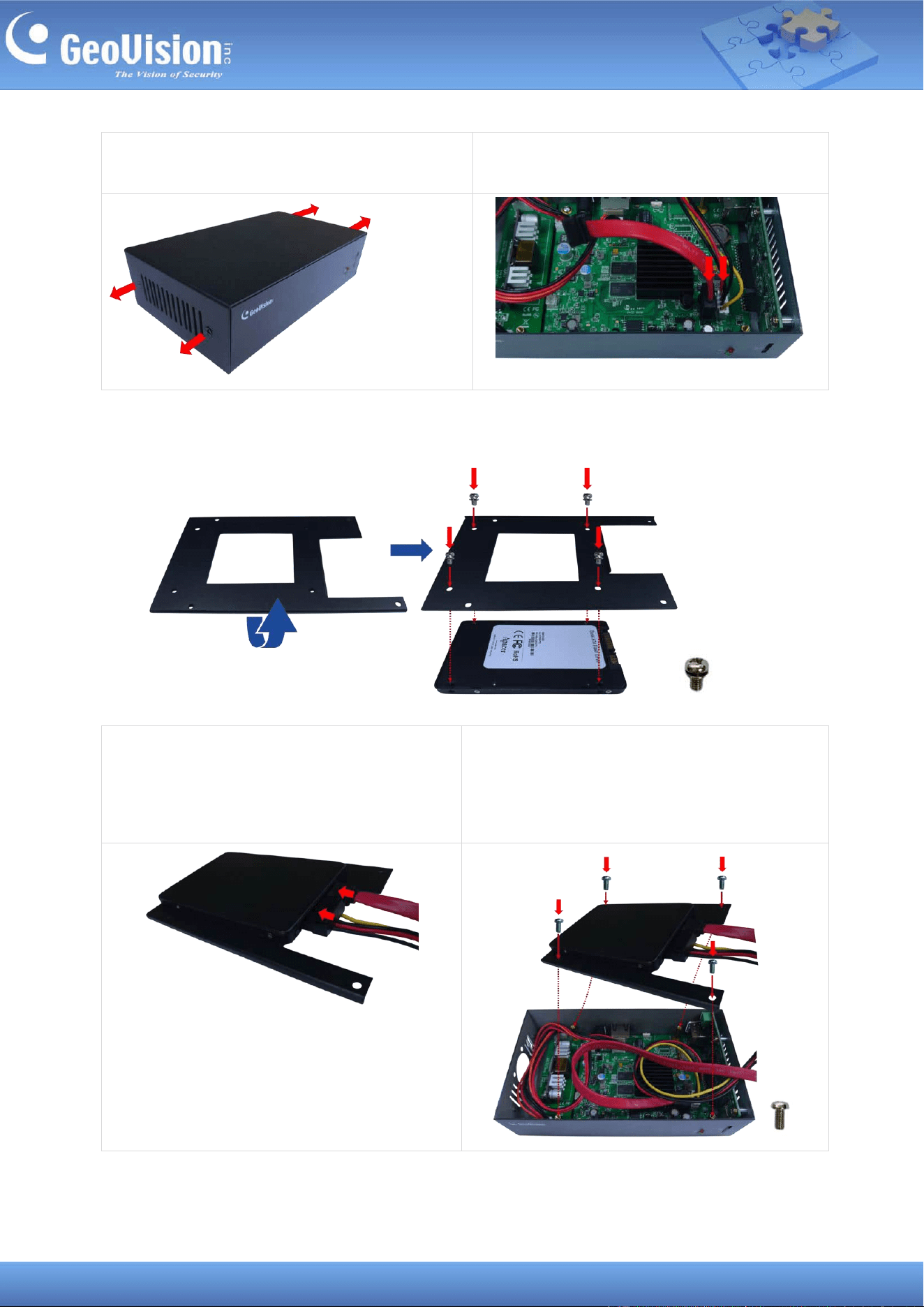
1. Loosen the 4 cover screws and take off
the cover of GV-Cloud Bridge Pro.
2. Connect the SATA Power Cable to the
GV-Cloud Bridge Pro system board.
3. Flip the mounting plate and attach it to the self-prepared SSD with 4 of the supplied
screws.
4. Turn over the SSD and mounting plate
assembly so that the SSD is on top, and
connect the SATA Power Cable from the
system board to the SSD.
5. Install the mounting plate to the mounting
standoffs using 4 of the supplied screws.
6. Fasten the cover back onto the housing to complete the SSD installation.
11
7 Accessing GV-Cloud Bridge Pro
When GV-Cloud Bridge Pro connects to a network with a DHCP server, it is allocated a
dynamic IP address. To access your device, follow the steps below.
1. Download and install the GV-IP Device Utility program.
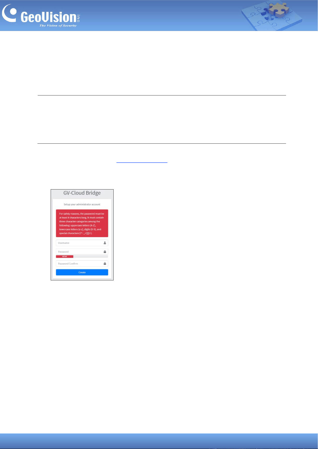
2. Locate your GV-Cloud Bridge Pro on the GV-IP Device Utility window, click its IP address,
and select Web Page. This webpage appears.
3. Type the necessary information to create a user account and click Create.
Note:
1. The PC used to access the Web interface must be on the same LAN as the GV-Cloud
Bridge Pro.
2. If the network does not have a DHCP server or is disabled, GV-Cloud Bridge Pro can be
reached using its default IP address 192.168.0.10, see 7.1 Assigning a Static IP Address.
12
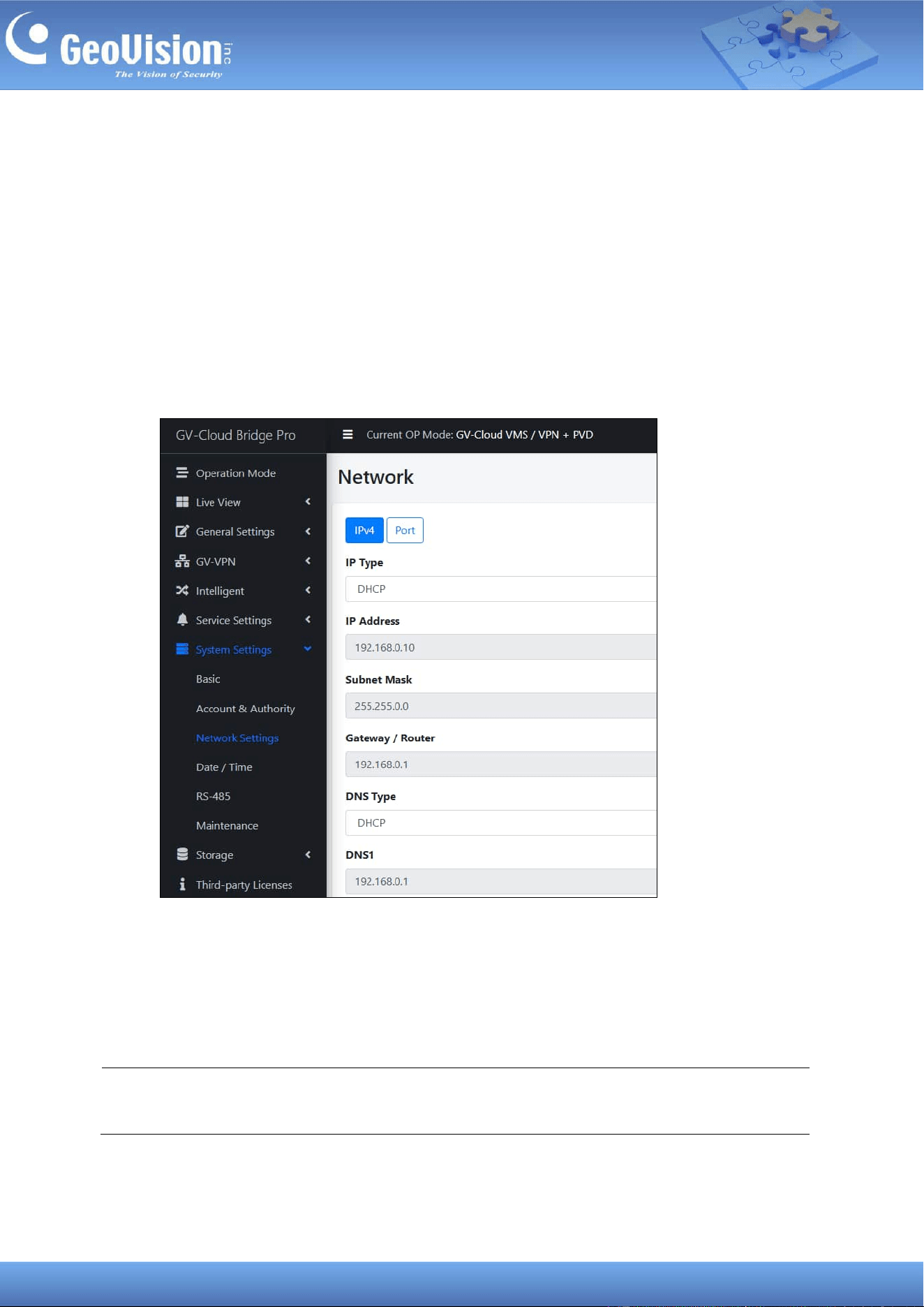
7.1 Assigning a Static IP Address
When GV-Cloud Bridge Pro connects to LAN without a DHCP server, it is assigned a static IP
address of 192.168.0.10. To avoid IP conflicts with other GeoVision devices, follow the steps
below to assign a new IP address.
1. Open your Web browser, and type the default IP address 192.168.0.10.
2. Type your username and password. Click Login.
3. In the left menu, click System Settings > Network Settings.
4. Select Static IP address as IP Type. Type the static IP address information, including
IP Address, Subnet Mask, Default Gateway and Domain Name Server.
5. Click Apply. The GV-Cloud Bridge Pro can now be reached using the static IP address
configured.
Note: This page is unavailable in the VPN Box mode. For details on different operation
modes, see 8 Operation Mode.
13
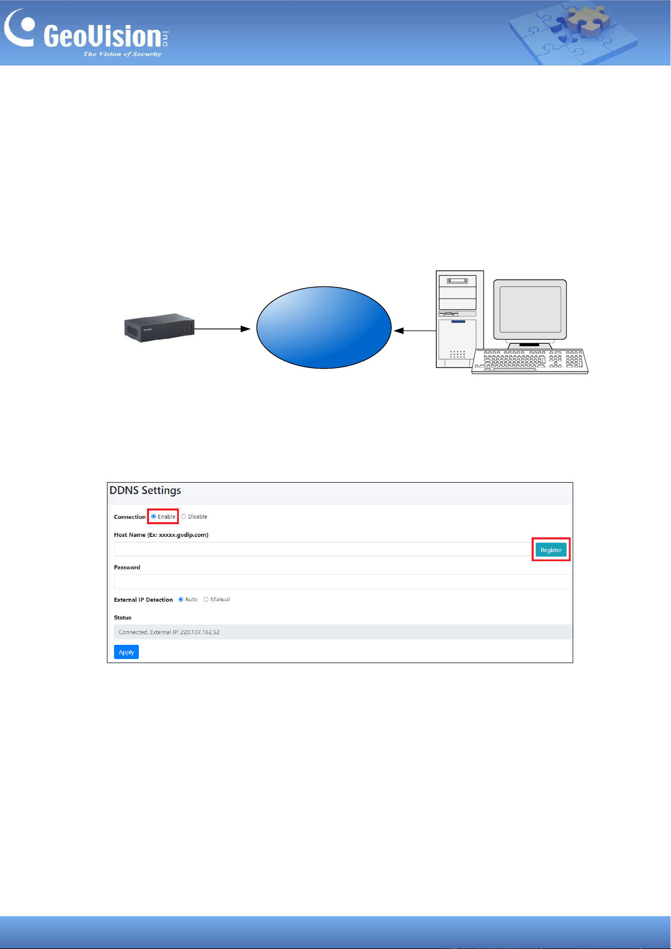
7.2 Configuring the DDNS Domain Name
DDNS (Dynamic Domain Name System) provides another way of accessing GV-Cloud Bridge
Pro when using a dynamic IP from a DHCP server. DDNS assigns a domain name to
GV-Cloud Bridge Pro so that it can always be accessed using the domain name.
Follow the steps below to apply for a domain name from GeoVision DDNS Server and
enable the DDNS function.
Internet
(DDNS Server)
GV-Cloud Bridge Pro
1. In the left menu, select Service Settings > DDNS.
2. Enable the connection, and click Register. You are directed to GV-Dynamic DNS
Service V2.
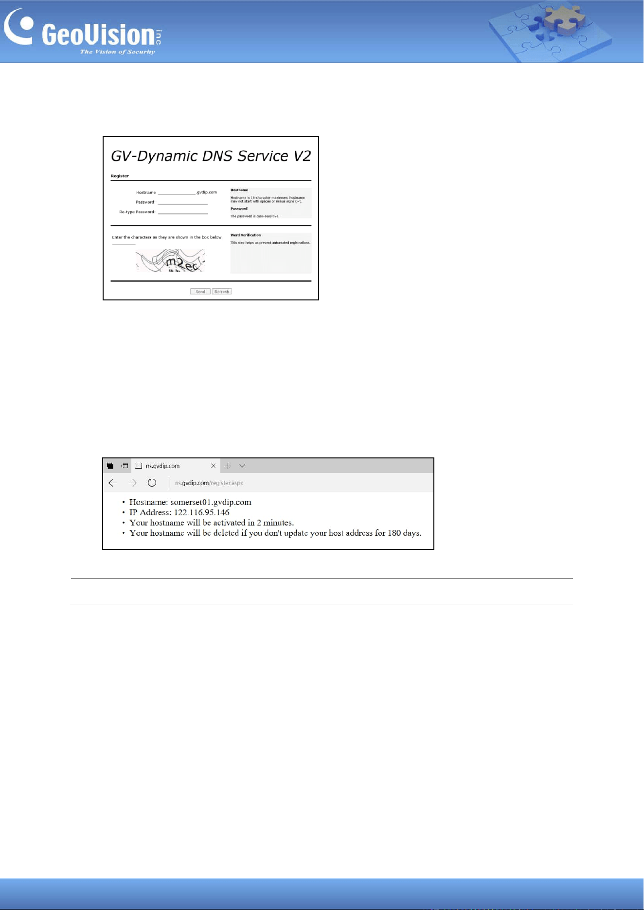
14
3. Type a Hostname of up to 16 characters, including "a ~ z", "0 ~ 9", and "-". A space or "-"
cannot be used as the first character.
4. Type a Password that is case-sensitive and at least 6 characters long. Type the
password again in the Re-type Password field to confirm.
5. Type the characters or numbers displayed in the Word Verification box. In this example,
type m2ec. Word Verification is not case-sensitive.
6. Click Send. This page shows after the registration process is complete. The Hostname
displayed is the domain name, consisting of the registered username and “gvdip.com”,
e.g. somerset01.gvdip.com.
Note: The registered username expires after three months of inactivity.
7. Return to the GV-Cloud Bridge Pro Web interface and type the Hostname and
Password registered on the DDNS Server.
8. Click Apply. The GV-Cloud Bridge Pro can now be accessed using the domain name.
15
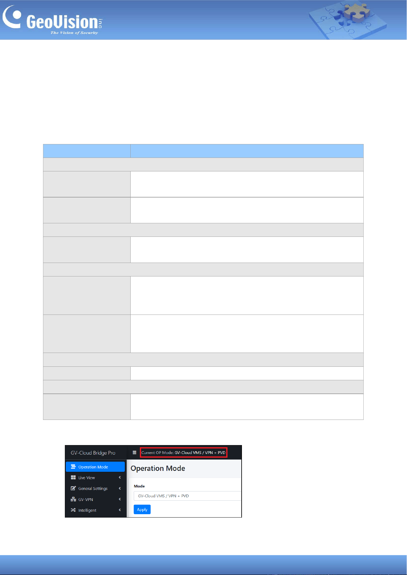
8 Operation Mode
Once logged in, select Operation Mode from the left menu. You can connect to GeoVision
software or services using one of four major operation modes. After selecting the desired
mode, GV-Cloud Bridge Pro will reboot for the changes to take effect. You can only choose
one operation mode at a time.
Operation Mode
Function
1. GV-Cloud VMS
GV-Cloud VMS / VPN
Connection to GV-Cloud VMS, GV-VPN (up to 8 IP devices),
GV-Eye
GV-Cloud VMS / VPN +
PVD
Connection to GV-Cloud VMS, GV-VPN (up to 8 IP devices),
GV-Eye; PVD (People and Vehicle Detection)
2. GV-Cloud Access Control
GV-Cloud Access / VPN
Connection to GV-Cloud VMS, GV-Cloud Access Control, GV-VPN
(up to 8 IP devices), GV-Eye
3. GV-Center V2 / Recording Server / Video Gateway / RTMP
CV2 / Video Gateway /
RTMP / VPN
Connection to GV-Center V2, GV-Dispatch Server, GV-Recording
Server / Video Gateway, GV-VPN (up to 8 IP devices), GV-Eye;
RTMP livestream
CV2 / Video Gateway /
RTMP / VPN + PVD
Connection to GV-Center V2, GV-Dispatch Server, GV-Recording
Server / Video Gateway, GV-VPN (up to 8 IP devices), GV-Eye;
RTMP livestream; PVD (People and Vehicle Detection)
4. GV-VPN Box
VPN Box (16 IP devices)
GV-VPN (up to 16 IP devices)
5. GV-CVW (GV-Cloud Video Watch)
GV-CVW + PVD
Connection to GV-Cloud Video Watch, GV-Eye; PVD (People and
Vehicle Detection)
The current operation mode is shown on the top of the Web interface.
16
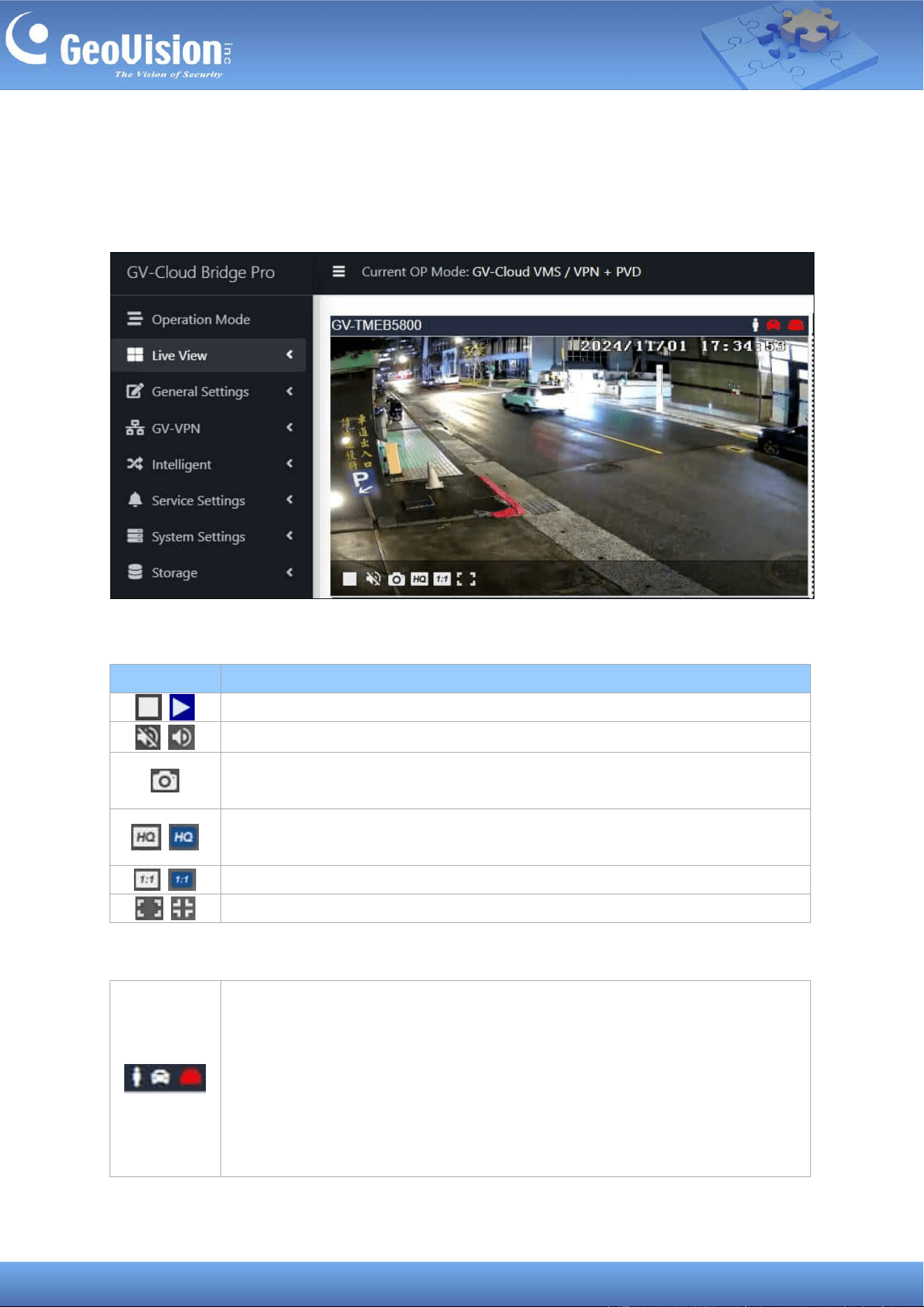
9 Live View
Once a camera is connected to GV-Cloud Bridge Pro, you can see its live view and use the
following functions for monitoring. For how to connect a camera, see 10.1 Connecting to IP
Cameras.
When you move the cursor over a channel, the following controls are available:
The indicators on a channel:
Icon
Function
The live view is enabled by default. Click to disable the live view.
The audio is disabled by default. Click to enable the audio.
Click to take a snapshot. The snapshot is saved immediately to your PC’s
Downloads folder in .png format.
The video resolution is set to the sub stream by default. Click to set the video
resolution to the main stream of high quality.
Picture-in-Picture (PIP) is disabled by default. Click to enable.
Screen is disabled by default. Click to view in full screen.
• People icon: Turn red when a person is detected. For the indicator to
work, it is required to enable People detection. See 15 Intelligent
Detection.
• Vehicle icon: Turn red when a vehicle is detected. For the indicator to
work, it is required to enable Vehicle detection. See 15 Intelligent
Detection.
• Recording: Turn red when the recording is active.
17
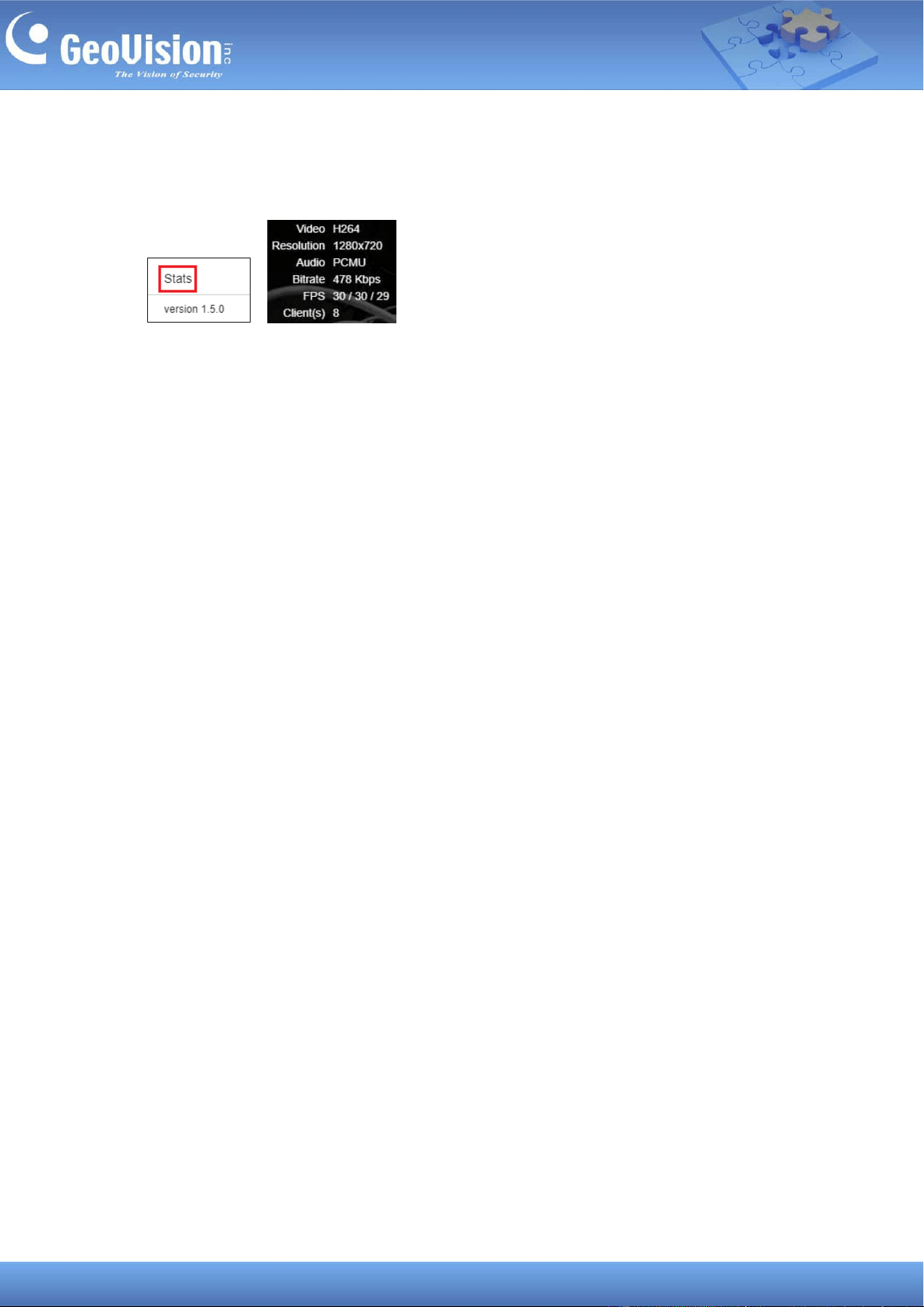
Additionally, you can right-click the live view image, and select Stats to see the current Video
(codec), Resolution, Audio (codec), Bitrate, FPS, and Client (the number of current
connections to the camera) in use.
18
10 General Settings
The following options are available under General Settings of the left menu. Procedures are
detailed in the following sections:
◼ Video Settings: See 10.1 Connecting to IP Cameras.
◼ IO Settings: See 10.2 Configuring Input / Output Settings.
◼ IO Box Settings: See 10.3 Connecting to I/O Box.
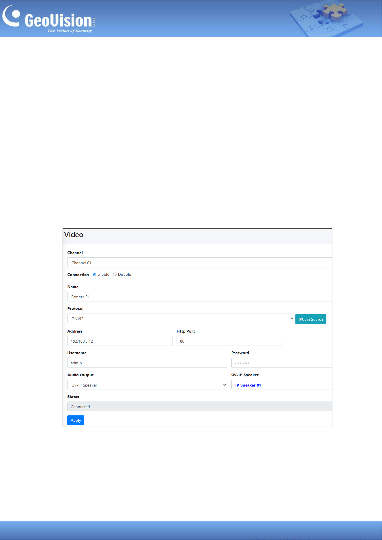
10.1 Connecting to IP Cameras
To set up connections to cameras, follow the steps below.
1. In the left menu, select General Settings > Video Setting.
2. For Channel, select one from Channel 01 to Channel 08 and enable the connection.
3. Type the connection information of the camera to be added. Optionally, click IPCam
Search to detect cameras on the same LAN, and then select a camera to automatically
import its connection information to this Video page.
4. Optionally select the Camera or a GV-IP Speaker to be the audio output.

19
5. Click Apply. Once connected, the Status field will display “Connected”.
20
10.2 Configuring Input / Output Settings
GV-Cloud Bridge Pro can manage up to eight input and eight output devices from cameras
and GV-IO Boxes.
The virtual inputs can be used to enable event alerts and start recordings when an input
trigger is detected. The virtual outputs can be triggered remotely via the GV-Center V2 central
monitoring station and the GV-Eye mobile app.
To set up I/O devices from the GV-IO Box, see 10.3 Connecting to I/O Box to set up GV-IO
Box in advance.
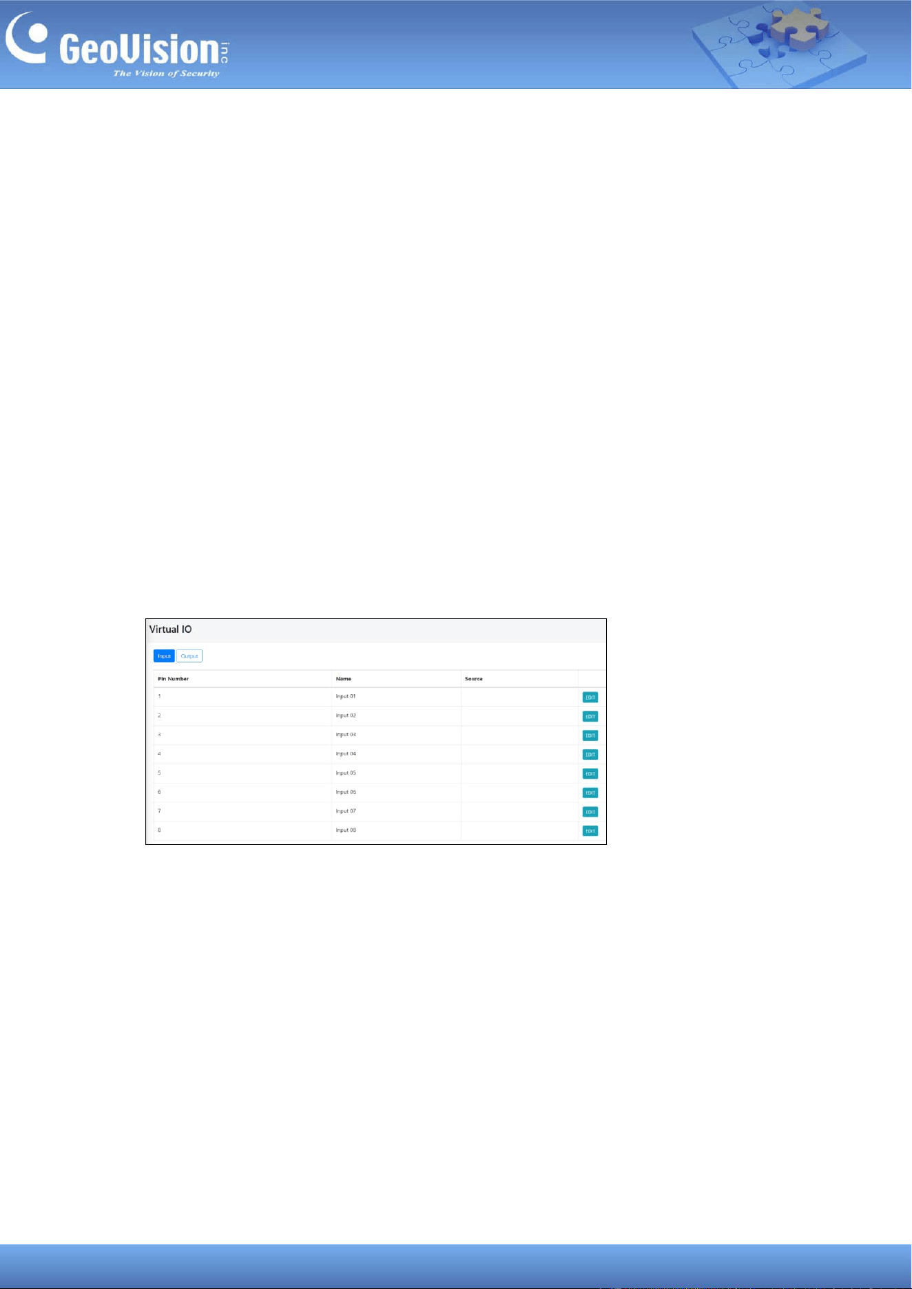
10.2.1 Input Settings
To configure an input device, follow the steps below.
1. In the left menu, select General Settings > IO Settings. This page appears.
2. To configure an input device, click Edit.
3. Select Camera or IO Box for Source. The edit page appears based on the selected
source.
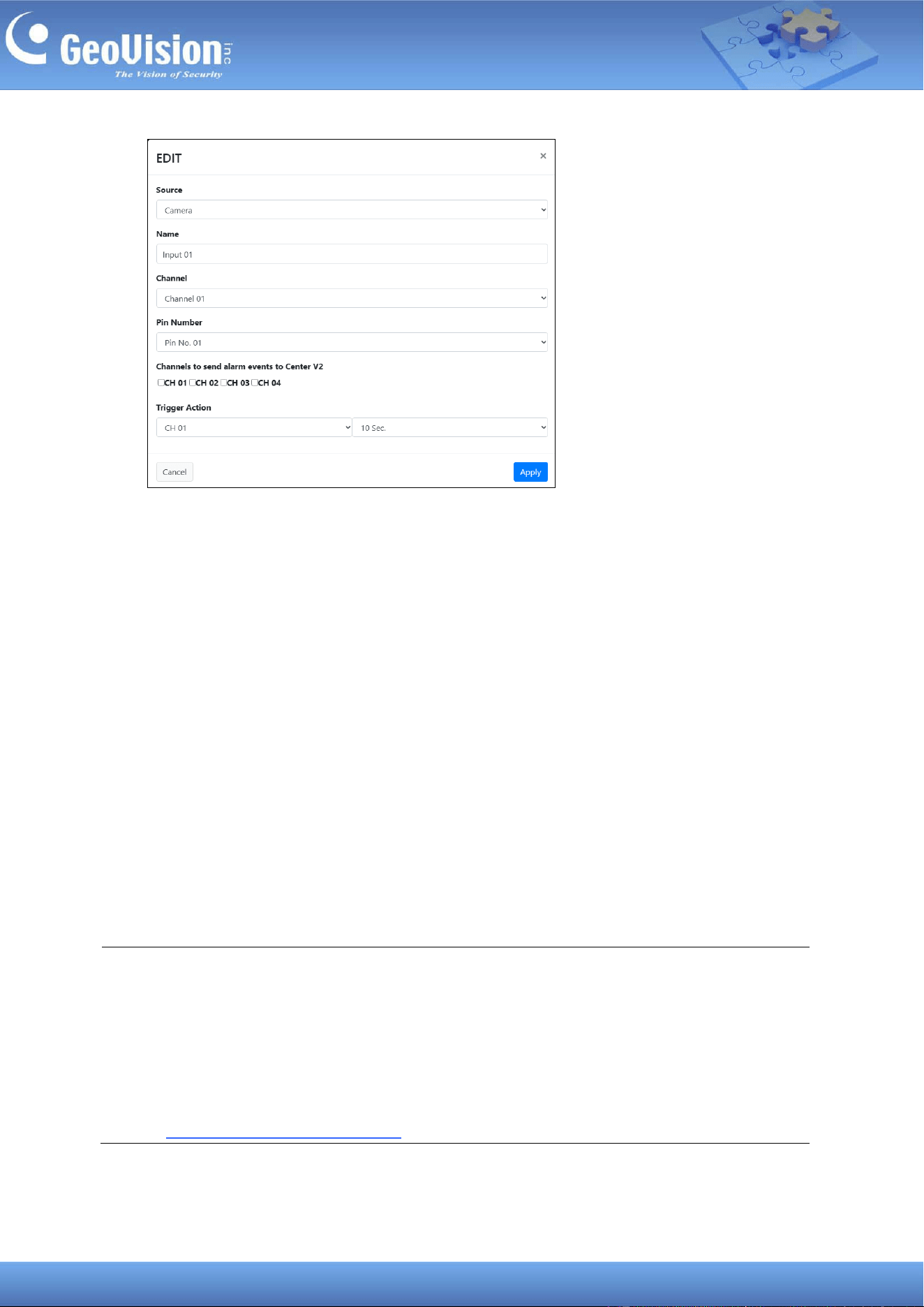
21
◼ Name: Type a desired name for the input settings.
◼ Channel / IO Box: Specify the camera channel or IO Box number based on the
selected source.
◼ Pin Number / IO Box Pin Number: Select the desired pin number for the input
device based on the selected source.
◼ Channels to send alarm events to Center V2: Select the desired cameras to send
event alerts to the GV-Center V2 central monitoring software when the input trigger
is detected.
◼ Trigger Action: Only available in the GV-Cloud VMS operation mode. Select the
recording channel and duration (up to 60 seconds) to start recording and notify
GV-Cloud VMS when the input trigger is detected. To trigger more than one channel
recording, configure another input trigger settings.
4. Click Apply.
Note:
1. To send event alerts and recordings to GV-Cloud VMS upon input triggers, ensure to
connect to GV-Cloud VMS. See 11.1 Connecting to GV-Cloud VMS for details.
2. Enable Attachment Mode under Subscriber Settings on GV-Center V2 to activate
the video attachment function. The Attachment Mode enabled on GV-Center V2 allows
recording of up to 60 seconds (30 seconds by default). See 1.4.2 Subscriber Settings
of GV-CMS Series User’s Manual for details.
22
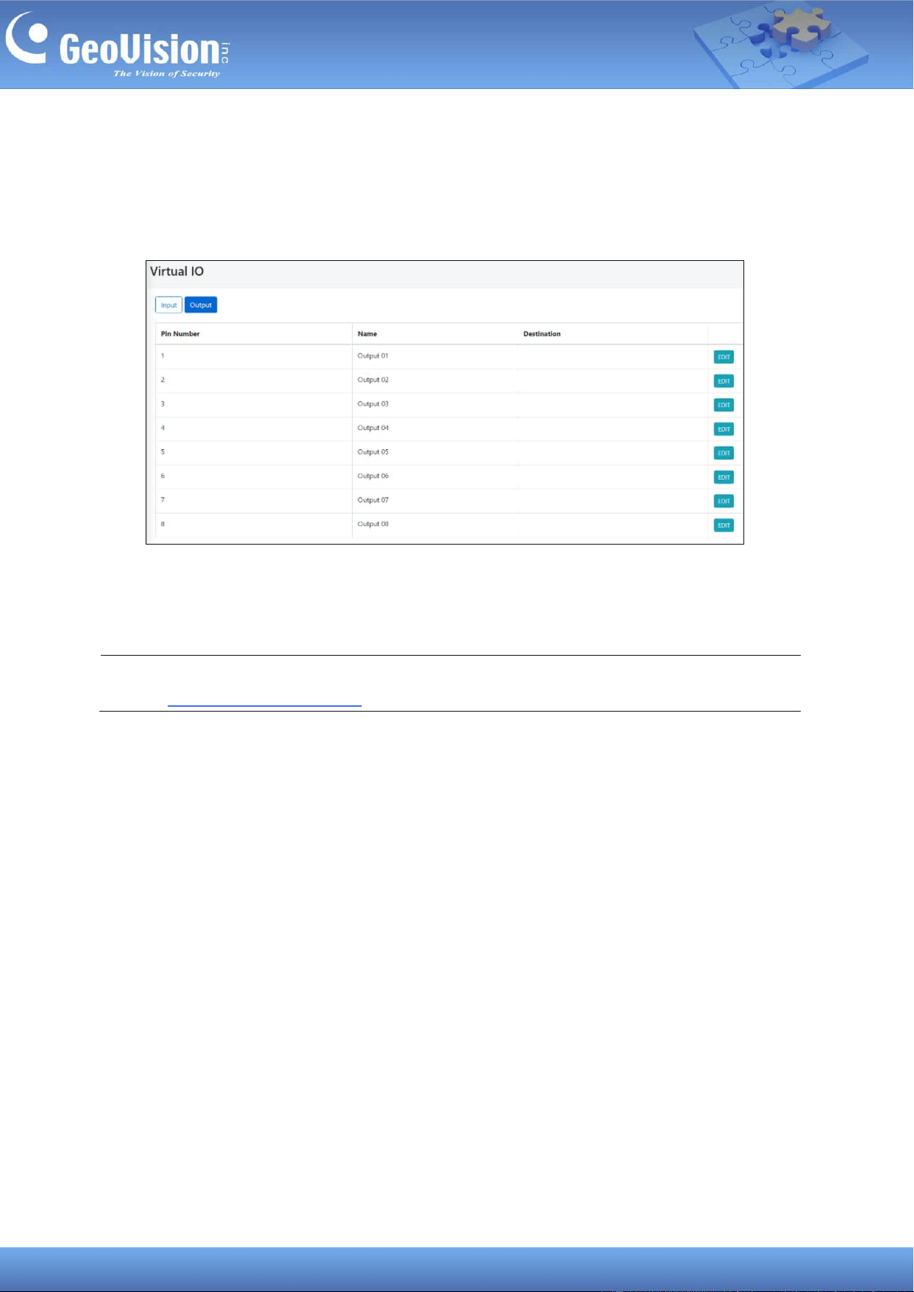
10.2.2 Output Settings
To configure an output device, follow the steps below.
1. Select Output on the Virtual IO page. This page appears.
2. To configure an output device, click Edit.
3. Follow Steps 3 ~ 4 in 1.9.2.1 Input Settings.
Note: To force a camera output to be triggered using the GV-Eye mobile app. See 8. Live
View in GV-Eye Installation Guide.
23
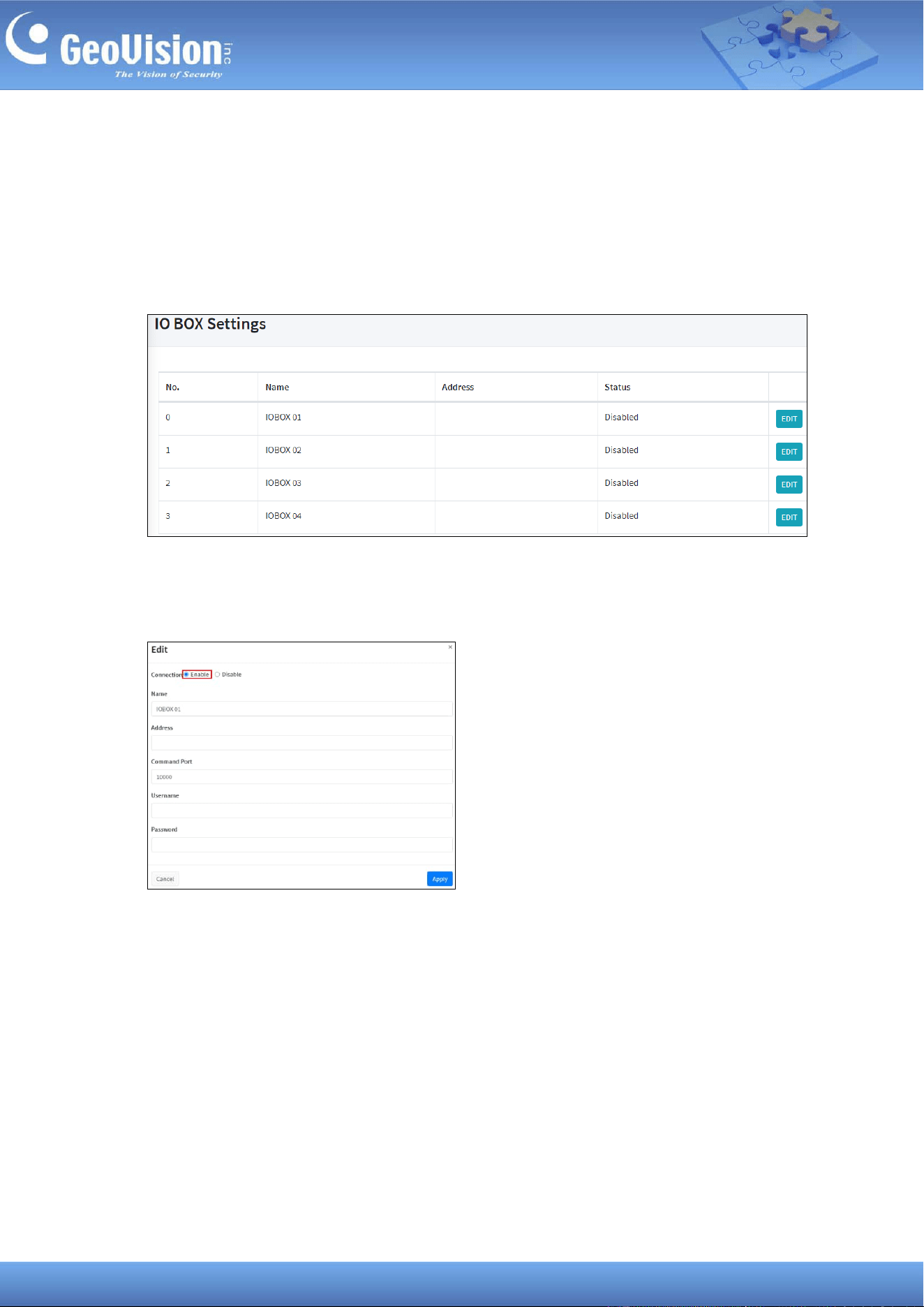
10.3 Connecting to I/O Boxes
GV-Cloud Bridge Pro can connect up to four GV-I/O Boxes. To connect to a GV-I/O Box,
follow the steps below.
1. In the left menu, click General Settings > IO BOX Settings. This page appears.
2. To configure a GV-I/O Box, click Edit.
3. Enable the connection and type the necessary information to connect the GV-I/O Box.
4. Click Apply.
5. To configure the input / output devices connected from the GV-I/O Box, see 10.2
Configuring Input / Output Settings.
24
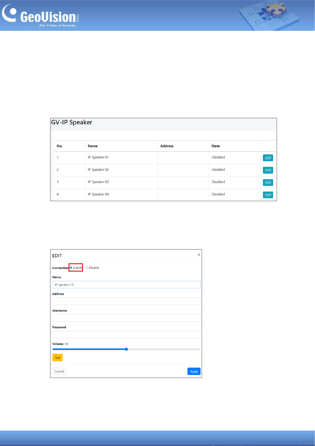
10.4 Connecting to IP Speakers
GV-Cloud Bridge Pro can connect up to eight GV-IP Speakers. The IP speaker can be
configured as the audio output of a camera channel, allowing the operator to talk to the
surveillance site via the speaker. To connect to a GV-IP Speaker, follow the steps below.
1. In the left menu, click General Settings > IP Speaker. This page appears.
2. To configure a GV-IP Speaker, click Edit.
3. Enable the connection and type the necessary information to connect the GV-IP
Speaker.
4. Click Test. Once connected, a success message will appear.
5. Click Apply.

25
6. To assign a GV-IP Speaker as a camera’s audio output, go to General Settings > Video
Setting. See Step 4 in 10.1 Connecting to IP Cameras.
Note: To talk to the surveillance site via a speaker, use the Microphone function in the WS
Player of GV-Cloud VMS, GV-Center V2, GV-Eye app, or GV-Cloud Video Watch.

26
11 Service Settings
The following options are available under Service Settings of the left menu. Procedures are
outlined in their respective sections:
◼ GV-Cloud VMS: See 11.1 Connecting to GV-Cloud VMS.
◼ GV-Cloud Access Control: See 11.2 Connecting to GV-Cloud Access Control.
◼ GV-Center V2: See 11.3 Connecting to GV-Center V2 / Dispatch Server.
◼ GV-Video Gateway: See 11.4 Connecting to GV-Recording Server / Video Gateway.
◼ GV-Relay: See 11.5 Connecting to GV-Relay (GV-Eye app).
◼ GV-CVW: See 11.6 Connecting to GV-CVW.
◼ Live Broadcast / RTMP: See 11.7 Live Broadcasting.
◼ DDNS: See 7.2 Configuring the DDNS Domain Name.
11.1 Connecting to GV-Cloud VMS
Cameras connected via GV-Cloud Bridge Pro can connect to GV-Cloud VMS, allowing for
cloud-based monitoring.
On GV-Cloud VMS
1. Add your GV-Cloud Bridge Pro to the host list on GV-Cloud VMS first. For details, see 2.3
Creating Hosts in GV-Cloud VMS User’s Manual.
On GV-Cloud Bridge Pro
2. In the left menu, select Operation Mode > GV-Cloud VMS / VPN, GV-Cloud VMS / VPN
+ PVD, or GV-Cloud Access Control / VPN.
3. Click Apply. When the device is rebooted, the mode will be applied.
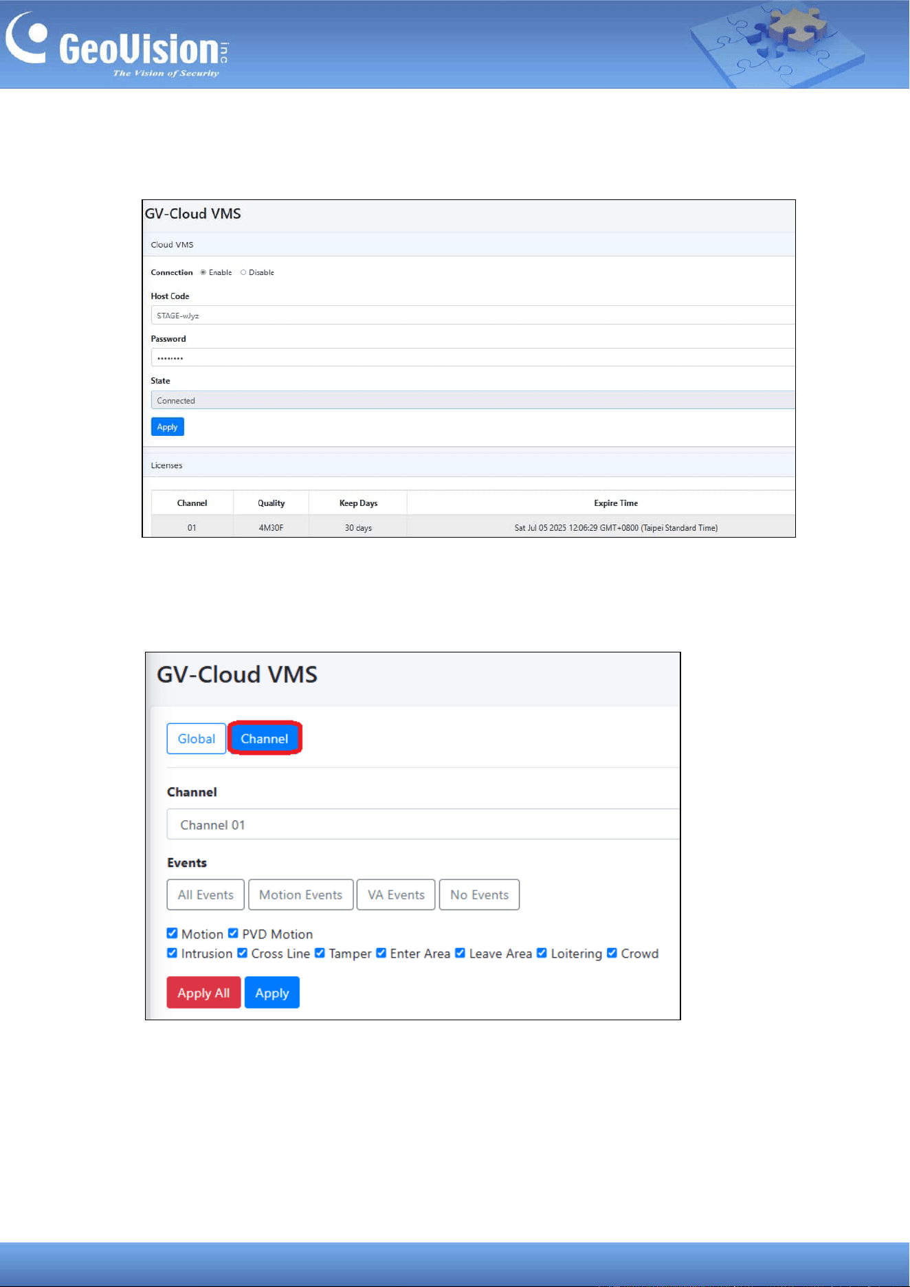
4. In the left menu, click Service Settings > GV-Cloud VMS.
27
5. Enable the connection, and type the Host Code and Password created on GV-Cloud
VMS (Step 1).
6. Click Apply. Once connected, the State will display “Connected”.
7. To select event types for transmission to GV-Cloud VMS, click the Channel tab.
8. Select a channel, and choose from All Events, Motion Events, VA Events, or No
Events. You can also check and uncheck a desired event. Click Apply.

28
Note:
1. When motion occurs, GV-Cloud Bridge Pro can send snapshots and video recordings
(up to 30 seconds, set to sub stream by default) to GV-Cloud VMS. It also transmits the
following AI events from AI-capable GV/UA-IP cameras, varying by model: PVD Motion
/ Intrusion / Cross Line / Enter Area / Leave Area / Loitering. For details, see 4.5.1
Compatible GV-IP Cameras for AI Search: GV-Cloud IP Cameras / Connected via
GV-Cloud Bridge / Cloud Bridge Pro in GV-Cloud VMS User’s Manual.
2. GV-Cloud Bridge Pro requires a memory card or SSD to record and notify GV-Cloud
VMS of events. To ensure that a storage device is operational, go to Storage > Disk in
the left menu and make sure the Status is OK.
3. When GV-Cloud Bridge Pro disconnects from GV-Cloud VMS over the Internet, videos
are stored on the Pro's storage device. Once connected, the videos will be sent to
GV-Cloud VMS.
4. When video playback lags, GV-Cloud VMS (Event Query) will display a “System
Overload” warning message. To resolve the issue, do one of the following measures:
i. Lower camera bitrate.
ii. Disable specific functions on part of connected cameras: GV/UA-IP and ONVIF
cameras (Motion detection); AI-capable GV/UA-IP cameras (AI functions:
Intrusion / PVD Motion / Cross Line / Enter Area / Leave Area).
5. When connecting to GV-Cloud VMS, make sure to enable ICMP Protocol from the
router for external communication.

29
11.2 Connecting to GV-Cloud Access Control
The controller and reader connected via GV-Cloud Bridge Pro can connect to GV-Cloud
Access Control, allowing for cloud-based monitoring.
The procedures are as the following:
• Step 1: Connect GV-Cloud Bridge Pro to GV-Cloud Access Control. See 11.2.1
Connecting to GV-Cloud Access Control.
• Step 2: Connect the GV-AS21xx / AS41xx controller or the GV-DFK1355 reader, via
GV-Cloud Bridge Pro, to GV-Cloud Access Control. See 11.2.2 Connecting the Controller
or Reader.
• Step 3: Only for the GV-DFK1355 reader to set the identification type. See 11.2.3 Setting
the Card Identifier.
30
11.2.1 Connecting to GV-Cloud Access Control
1. In the left menu, select Operation Mode > GV-Cloud Access Control / VPN.
2. Click Apply. When the device is rebooted, the mode will be applied.
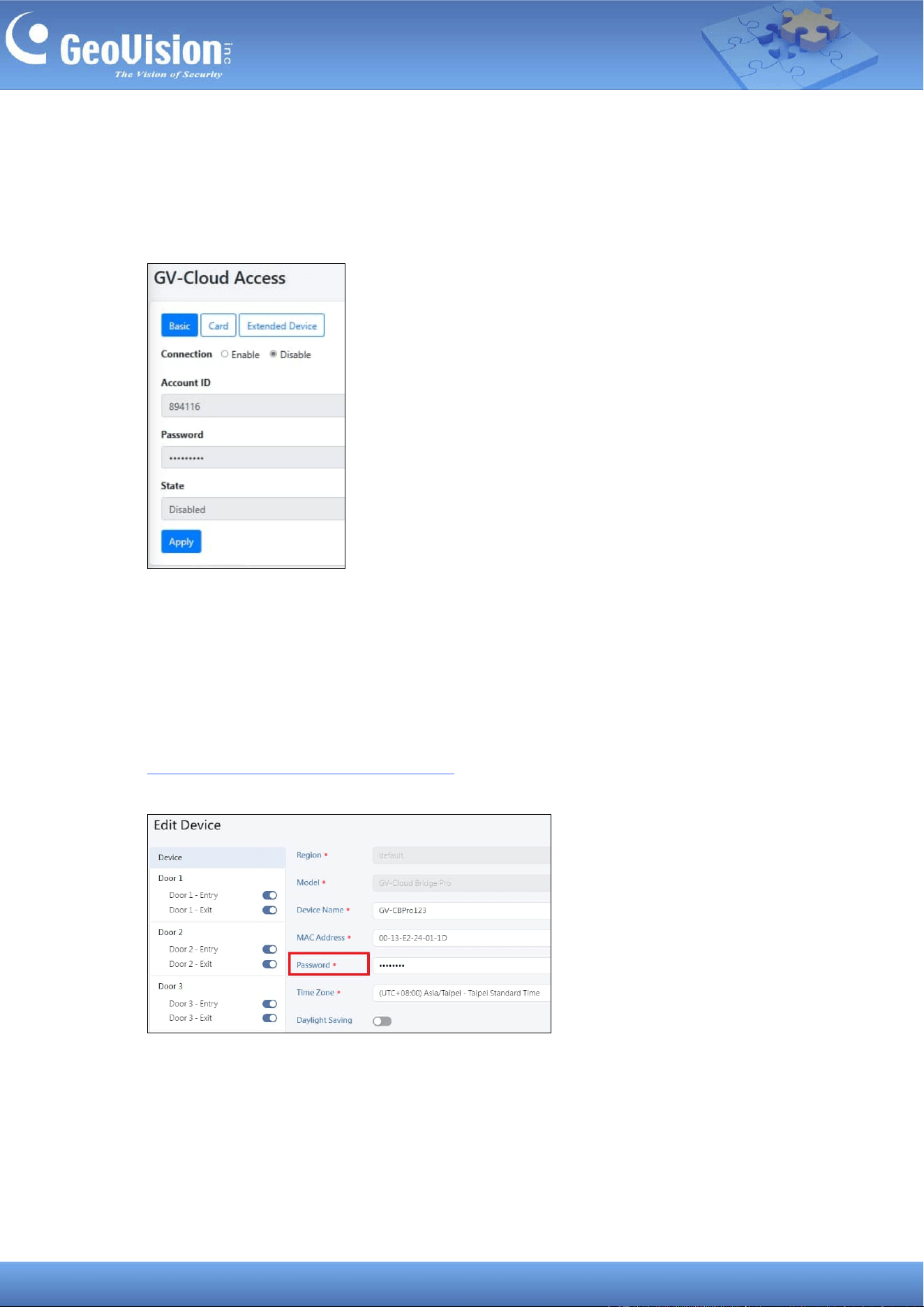
3. In the left menu, click Service Settings > GV-Cloud Access Control.
◼ Account ID: Type your GV-Cloud account ID.
◼ Password: Create a password for the GV-Cloud Bridge Pro.
4. Click Apply. When the device is added to GV-Cloud Access Control, the State will
display “Connected”.
5. Add the GV-Cloud Bridge Pro to GV-Cloud Access Control. See 4.2.1 Adding a Device in
GV-Cloud Access Control User’s Manual. Note that the password entered on GV-Cloud
Access Control must match that created on the GV-Cloud Bridge Pro (Step 3).
31
11.2.2 Connecting the Controller or Reader
GV-Cloud Bridge Pro allows you to connect the GV-AS21xx or GV-AS41xx controller or the
GV-DFK1355 reader to the GV-Cloud Access Controller. On the GV-Cloud Access Control
page, click the Extended Device tab.
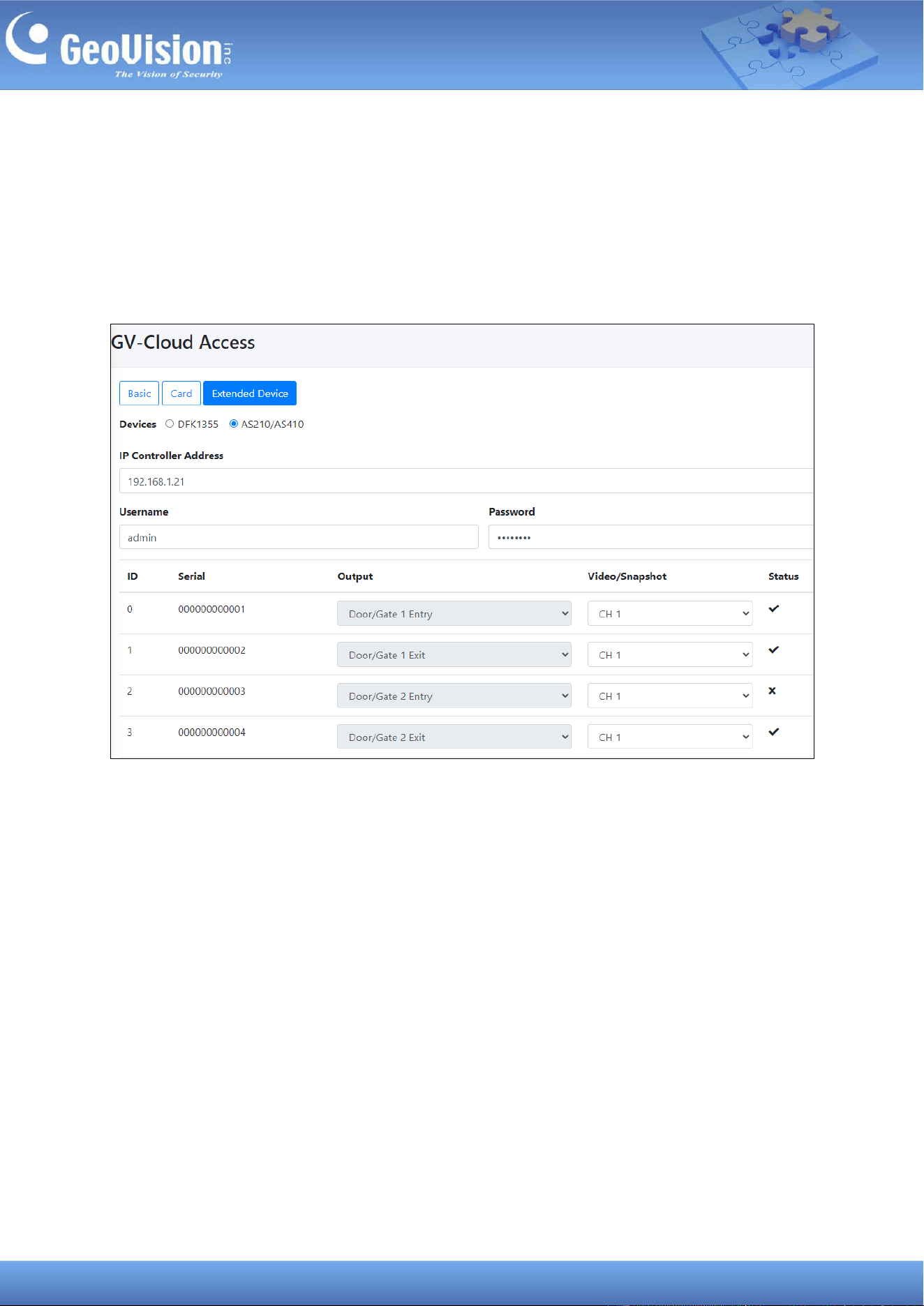
To connect the GV-AS21xx / AS41 xx controller:
1. In the left menu, click Service Settings > GV-Cloud Access Control, and select the
Extended Device tab.
2. Select AS210/410 as Devices.
3. Type the controller’s IP address under IP Controller Address.
4. Type the login Username and Password of the controller.
5. Click Apply. When the controller is connected to GV-Cloud Access Control, the Status
for each ID will display a checkmark.
6. Assign a channel number from the Video/Snapshot dropdown list to its relevant door
number. The ID# and Output# (door number/function) are fixed.
7. Click Apply again.
You can now swipe a card on any reader connected on the controller. A “Invalid Card”
message should appear on GV-Cloud Access Control.
32
To connect the GV-DFK1355 reader:
Using the RS-485 interface of GV-Cloud Bridge Pro, you can connect up to 8 GV-DFK1355
readers to GV-Cloud Access Control.
Note: To define the sequence of multiple readers when connected to a single RS-485
interface, use the DFK1355 Setup AP. See 8.7 ID and Card Identifier Settings in GV-Card
Reader User’s Manual.
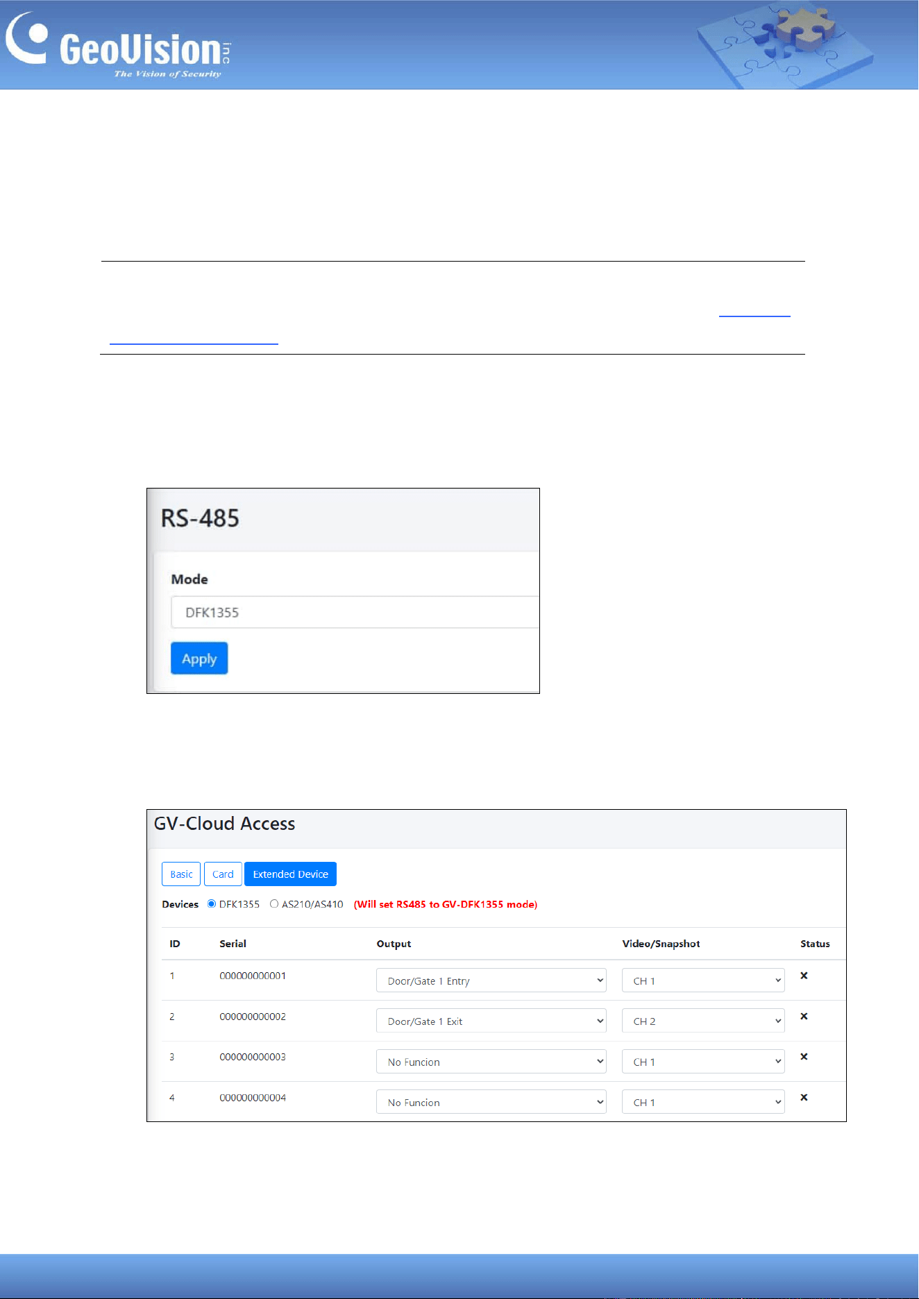
1. Connect the GV-DFK1355 reader to the RS-485 interface of GV-Cloud Bridge Pro.
2. In the left menu, select System Settings > RS-485, and select DFK1355 as Mode. Click
Apply.
3. In the left menu, click Service Settings > GV-Cloud Access Control, and select the
Extended Device tab.
4. Select DFK1355 as Devices.
33
5. For each reader, specify the door number/function from the Output dropdown list, as well
as the channel number for video streams and snapshots from the Video/Snapshot
dropdown list.
6. Click Apply. When the reader is connected to GV-Cloud Access Control, the Status for
each ID will display a checkmark.
You can now swipe a card on the reader. A “Invalid Card” message should appear on
GV-Cloud Access Control.
34
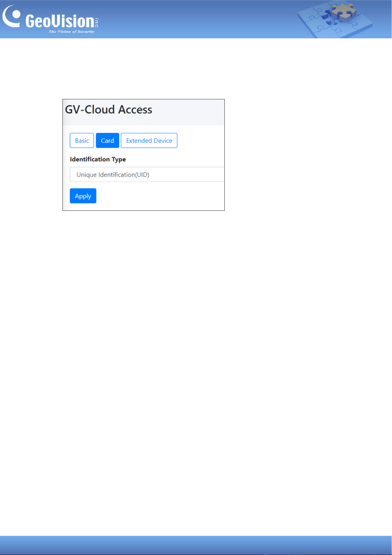
11.2.3 Setting the Card Identifier
To set the GV-DFK1355 reader to reader Unique Identification (UID) or GeoVision
Identification (GID), click the Card tab on the GV-Cloud Access page.
35
11.3 Connecting to GV-Center V2 / Dispatch Server
Cameras connected via GV-Cloud Bridge Pro can connect to GV-Center V2 or GV-Dispatch
Server, allowing for centralized monitoring.
1. In the left menu, select Operation Mode > CV2 / Video Gateway / RTMP or CV2 /
Video Gateway / RTMP + PVD.
2. Click Apply. When the device is rebooted, the mode will be applied.
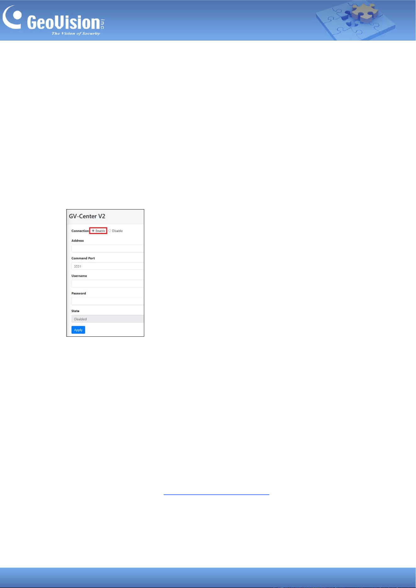
3. In the left menu, click Service Settings > GV-Center V2.
4. Enable the connection, and type the necessary information for GV-Center V2 / Dispatch
Server to connect.
5. Click Apply. Once connected, the State field will display “Connected”.
When working with GV-Center V2 and GV-Dispatch Server, note the following:
• GV-Center V2 V18.4.1 and GV-Dispatch Server V18.2.0A do not support AI and PVD
events from GV-Cloud Bridge Pro. The following events are supported: motion, input
trigger, output trigger, video lost, video resumed, tampering, and scene change.
• GV-Center V2 AI version supports AI and PVD events. The following events are
supported, varying by camera model: PVD Motion, Intrusion, Cross Line, Enter Area,
Leave Area, Loitering, and regular events (e.g. motion). For details, see Appendix K.
Compatible GV-IP Cameras for Events in V20: GV-IP Cameras Connected via GV-Cloud
Bridge / Cloud Bridge Pro in GV-CMS Series User’s Manual.
36
Enable Attachment Mode under Subscriber Settings on GV-Center V2 to activate the video
attachment function. The Attachment Mode enabled on GV-Center V2 allows recording of up
to 60 seconds (30 seconds by default). See 1.4.2 Subscriber Settings of GV-Center V2 User’s
Manual for details.
Note: GV-Center GV-Cloud Bridge Pro requires a memory card or SSD to record and notify
GV-Center V2 of events. To ensure that a storage device is working properly, go to Storage
> Disk in the left menu and make sure the Status is OK.
37
11.4 Connecting to GV-Recording Server / Video Gateway
Cameras connected via GV-Cloud Bridge Pro can make a passive connection to the
GV-Recording Server / Video Gateway, allowing for large-scale video recording and
transmitting.
Note:
1. The support for GV-Recording Server / Video Gateway is coming soon.
2. GV-Cloud Bridge Pro allows 3
rd
party IP cameras to establish passive connections to
GV-Recording Server / Video Gateway without port forwarding.
On GV-Recording Server
1. To create passive connection, first follow the instructions in 4.2 Passive Connection of
GV-Recording Server User’s Manual.
On GV-Cloud Bridge Pro
2. In the left menu, select Operation Mode > CV2 / Video Gateway / RTMP or CV2 /
Video Gateway / RTMP + PVD.
3. Click Apply. When the device is rebooted, the mode will be applied.
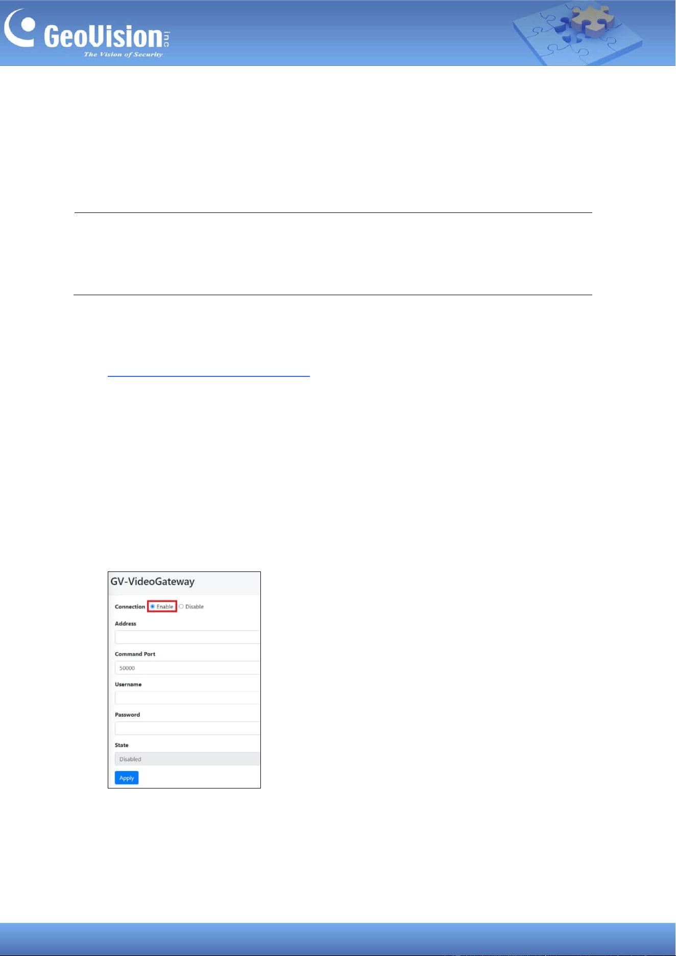
4. In the left menu, click Service Settings > GV-Video Gateway.
5. Enable the connection, and type the necessary information for GV-Recording Server /
Video Gateway to connect.
6. Click Apply. Once connected, the State field will display “Connected”.
38
11.5 Connecting to GV-Relay (GV-Eye App)
Cameras connected via GV-Cloud Bridge Pro can be monitored using the GV-Eye mobile app.
Follow the steps below to enable the connection to GV-Eye.
The GV-Relay QR code service on this page allows you to connect to the GV-Eye mobile app
by scanning the QR code displayed.
Note: Connecting GV-Eye by GV-Relay QR code is a paid service. Each GV-Relay account
receives 10 GB of free data every month, with more data available for purchase using the
GV-Eye mobile app. For details, refer to Chapter 5. GV-Relay QR Code in GV-Eye Installation
Guide.
On GV-Cloud Bridge Pro
1. In the left menu, select an Operation Mode, except VPN Box.
2. Click Apply. When the device is rebooted, the mode will be applied.
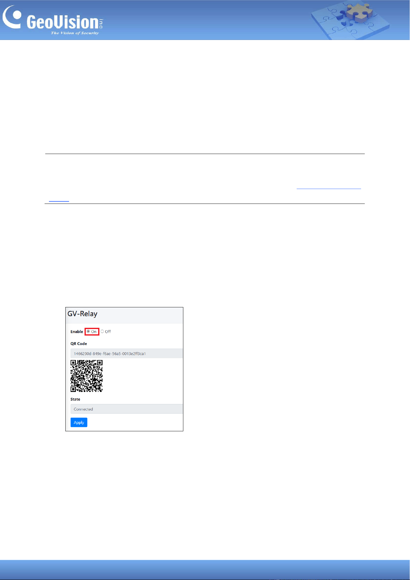
3. In the left menu, click Service Settings > GV-Relay.
4. Select On to enable the service. If the operation mode you selected includes GV-Cloud
VMS, the GV-Relay function is enabled automatically.
39
On GV-Eye App
1. Tap Add on the Camera / Group List page of GV-Eye to access the Add Device
page.
2. Tap QR-code scan , and hold your mobile device over the QR code on the GV-Relay
page.
3. Once the scanning is complete, type the name and login credentials of your GV-Cloud
Bridge Pro.
4. Click Get Information. All cameras from your GV-Cloud Bridge Pro are displayed.
5. Select the cameras you want to view on GV-Eye and click Save. The selected cameras
are added to GV-Eye under a Host Group.
40
11.6 Connecting to GV-CVW
Cameras connected via GV-Cloud Bridge Pro can connect to GV-CVW (GV-Cloud Video
Watch), allowing for centralized monitoring.
1. In the left menu, select Operation Mode > CVW + PVD.
2. Click Apply. When the device is rebooted, the mode will be applied.
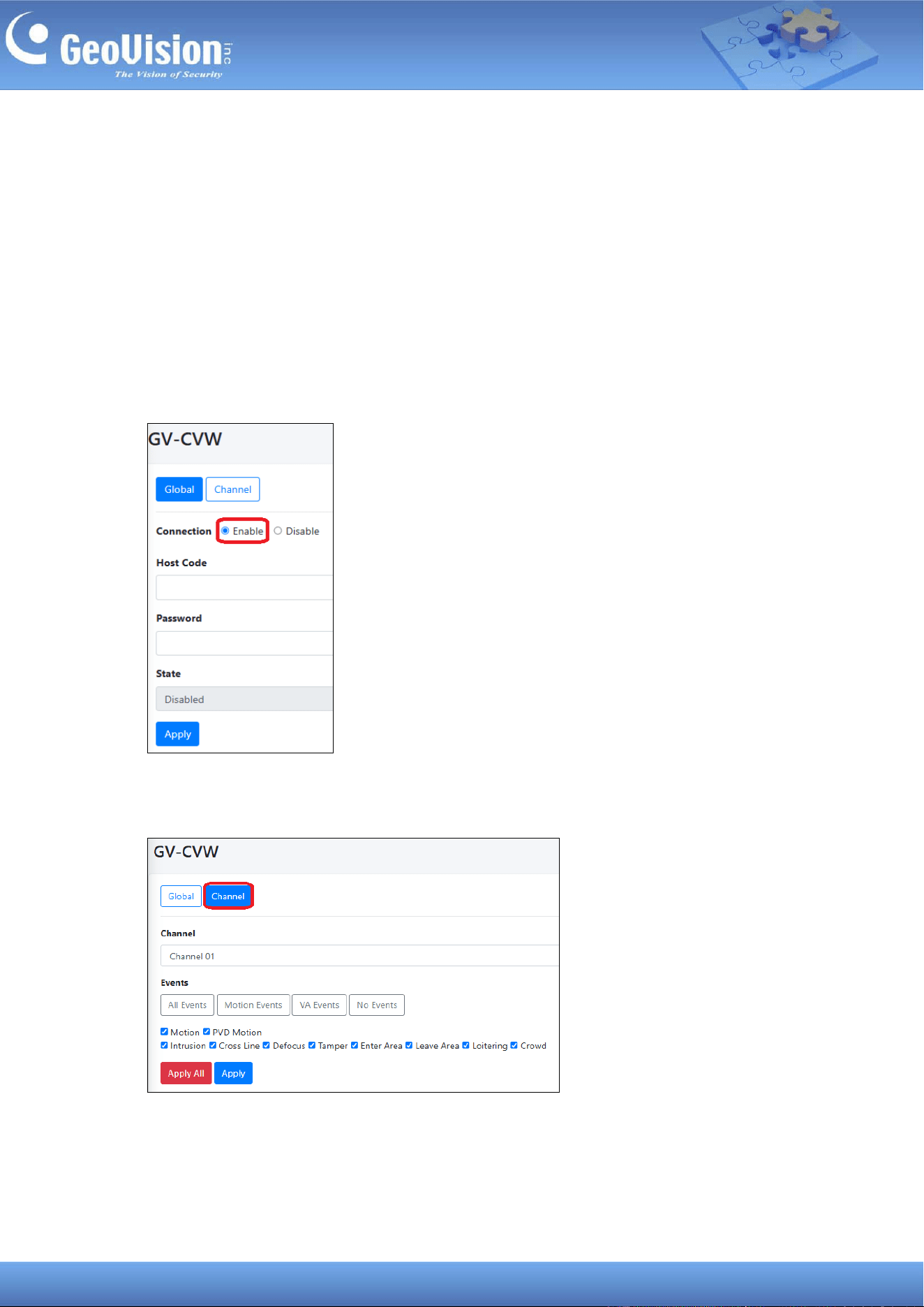
3. In the left menu, click Service Settings > GV-CVW.
4. Enable the connection, and type the connection information Host Code and Password
for GV-Cloud Video Watch to connect.
5. Click Apply. Once connected, the State field will display “Connected”.
6. To select event types for transmission to GV-Cloud Video Watch, click the Channel tab.
41
7. Select a channel, and choose from All Events, Motion Events, VA Events, or No
Events. You can also check and uncheck a desired event. Click Apply.
Note: GV-Center GV-Cloud Bridge Pro requires a memory card or SSD to record and notify
GV-Cloud Video Watch of events. To ensure that a storage device is working properly, go to
Storage > Disk in the left menu and make sure the Status indicates OK.
42
11.7 Live Broadcasting
Cameras connected via GV-Cloud Bridge Pro can connect to YouTube or Twitch for live
broadcasting. The user interfaces vary per platform. Locate the options specific to your
platform. In the following procedures, we use YouTube as an example.
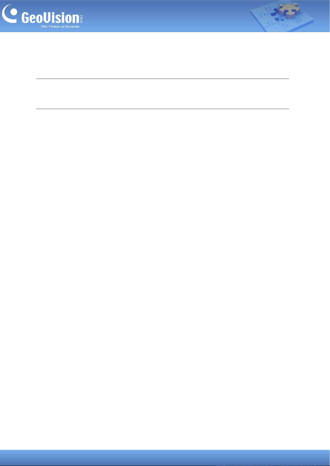
On YouTube
1. Log in to your YouTube account, click the Create icon and select Go live.
2. On the welcome page to Live control room, select Start for Right now, and then GO for
Streaming software.
3. Select the Manage icon, and then SCHEDULE STREAM.
4. Specify the necessary information for your new stream. Click CREATE STREAM.
43
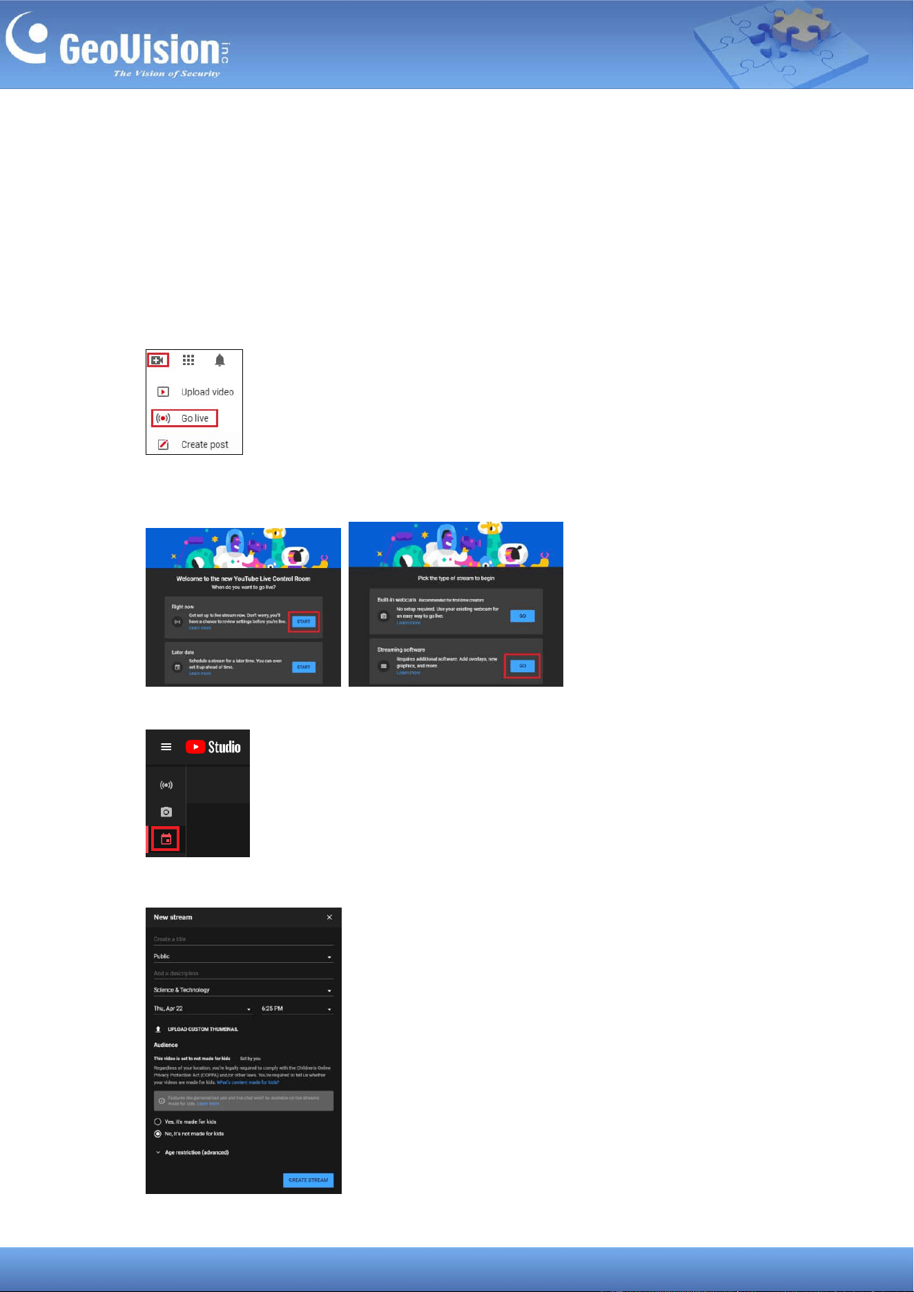
5. Make sure to disable Enable Auto-stop, and enable Enable DVR. The Stream Key and
Stream URL are now available.
On GV-Cloud Bridge Pro
6. In the left menu, select Operation Mode > CV2 / Video Gateway / RTMP / VPN or CV2 /
Video Gateway / RTMP / VPN + PVD.
7. Click Apply. When the device is rebooted, the mode will be applied.
8. Click Service Settings > Live Broadcast / RTMP.
9. Enable the connection, and copy and paste the Stream Key and Stream URL from
YouTube to the setting page.
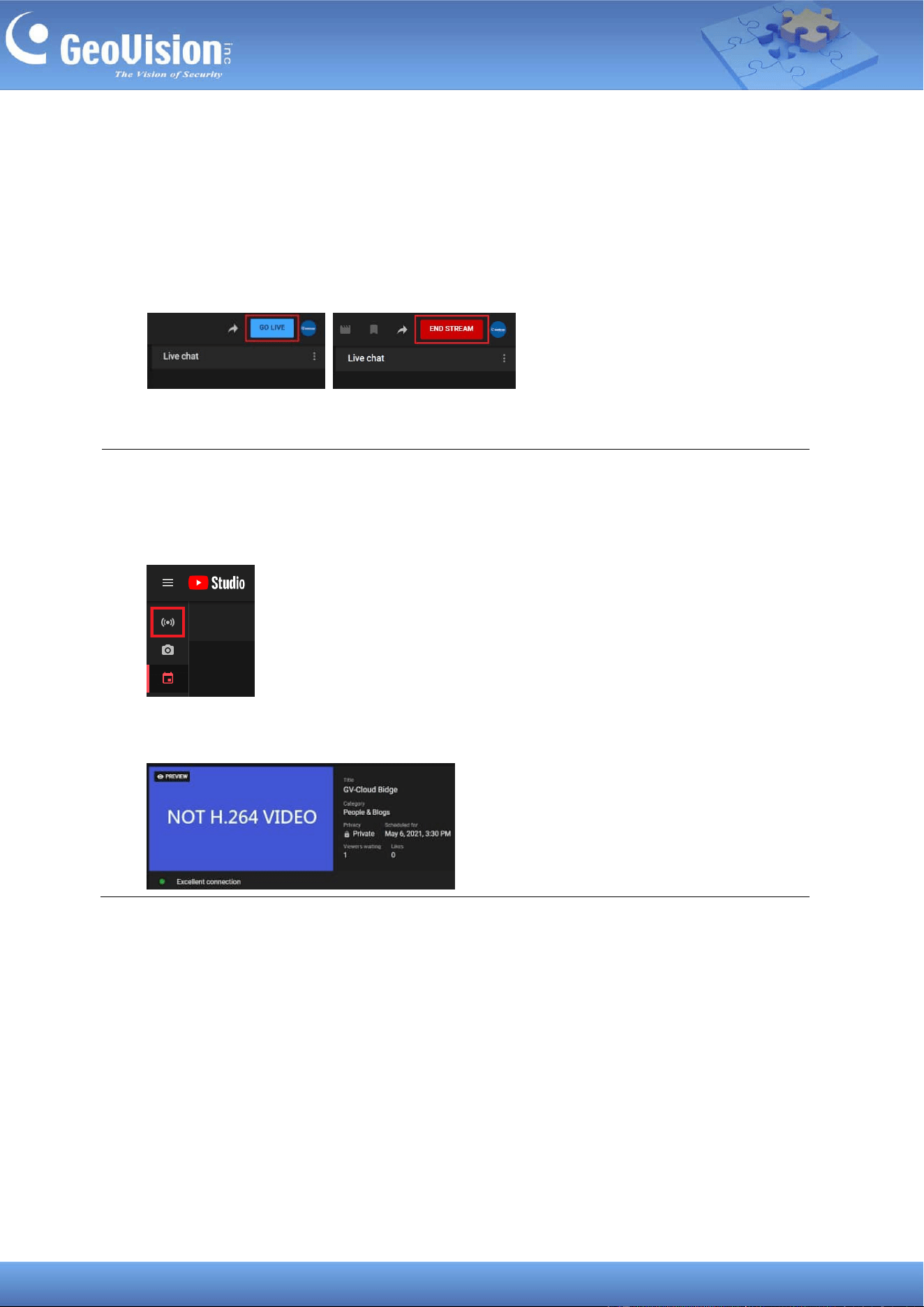
44
10. Select PCM or MP3 for Audio, or select Mute for no sound.
11. Click Apply. You can now view the live view broadcast from the GV-Cloud Bridge Pro in
the YouTube preview window.
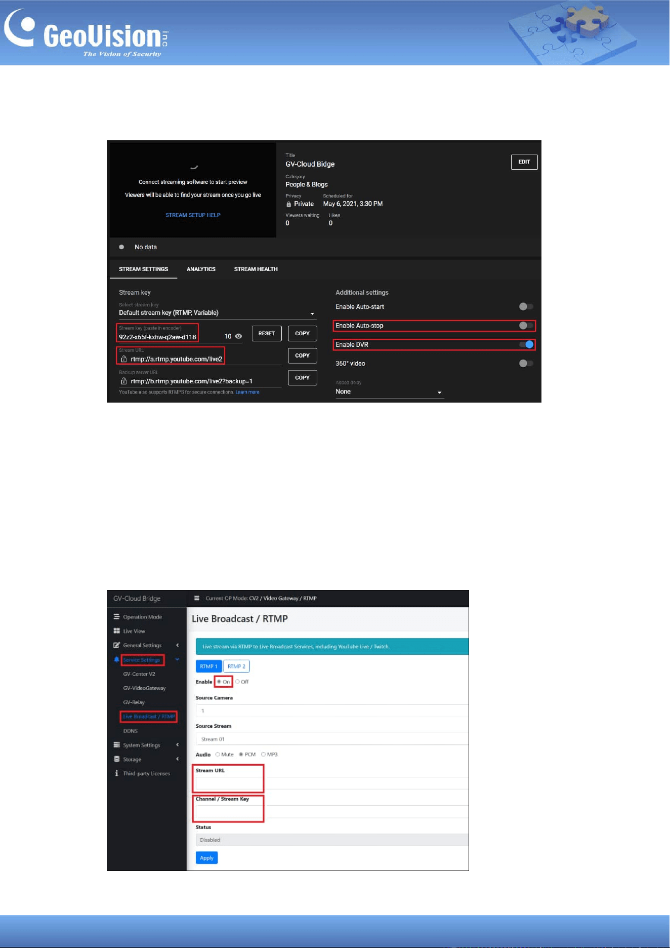
On YouTube
12. Click GO LIVE to begin streaming, and END STREAM to end streaming.
IMPORTANT:
1. At Step 3, do not select the Stream icon to configure the live broadcast. This will
enable Enable Auto-stop by default, and disconnect from the live broadcast when the
Internet connection is unstable.
2. Make sure to set your camera’s video compression to H.264. If not, the live broadcast
will appear as follow:
45
12 System Settings
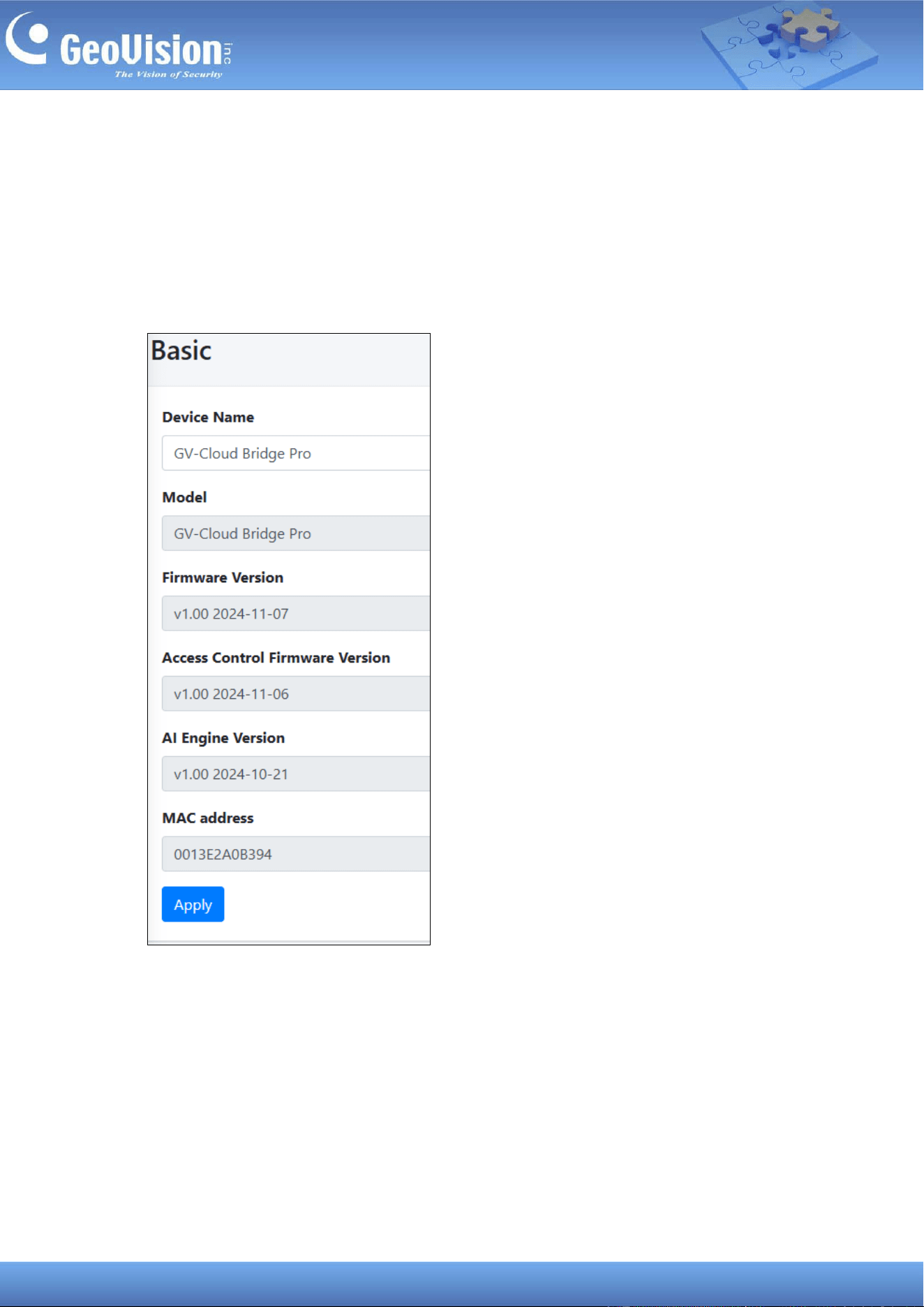
12.1 Basic
The Baisc page displays the firmware version, engine version, MAC address, and device
name. You can also change the device name.
46
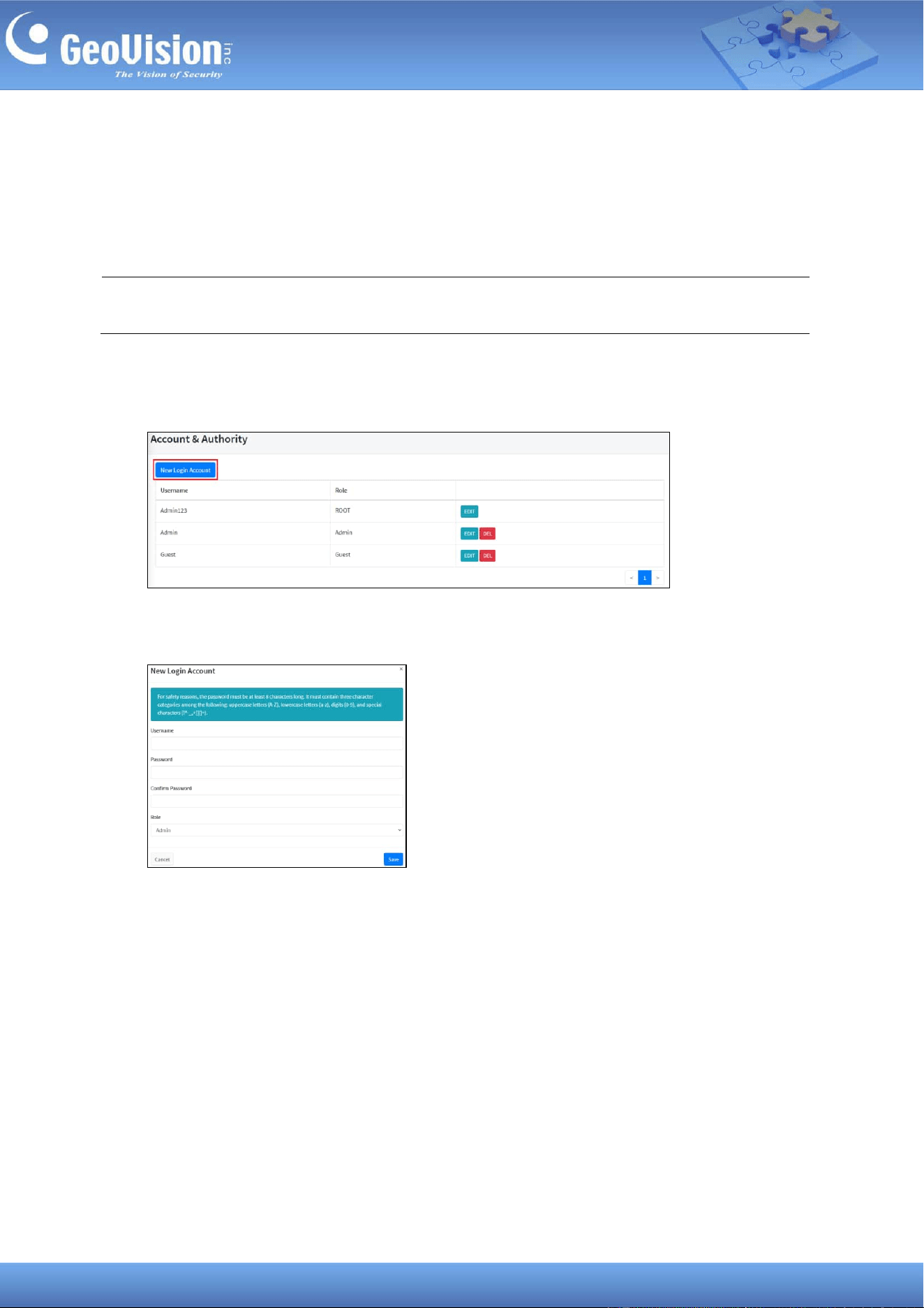
12.2 Account and Authority
GV-Cloud Bridge Pro supports up to 32 user accounts. To manage user accounts, follow the
steps below.
Note: The ROOT account is created by default and cannot be removed. The account has
full access to all functions.
1. In the left menu, click System Settings > Account & Authority.
2. To add a new account, click New Login Account.
3. Type the necessary information and select a role as Admin or Guest. Click Save.
◼ Admin: This role can be added or deleted. The Admin account has full access to all
functions.
◼ Guest: This role can be added or deleted. The Guest account can only access the
live view.
4. To modify the password or role of an account, click Edit for the account and make your
changes. Click Save.
47
12.3 Network Settings
For details, see 7.1 Assigning a Static IP Address or 7.2 Configuring the DDNS Domain
Name.
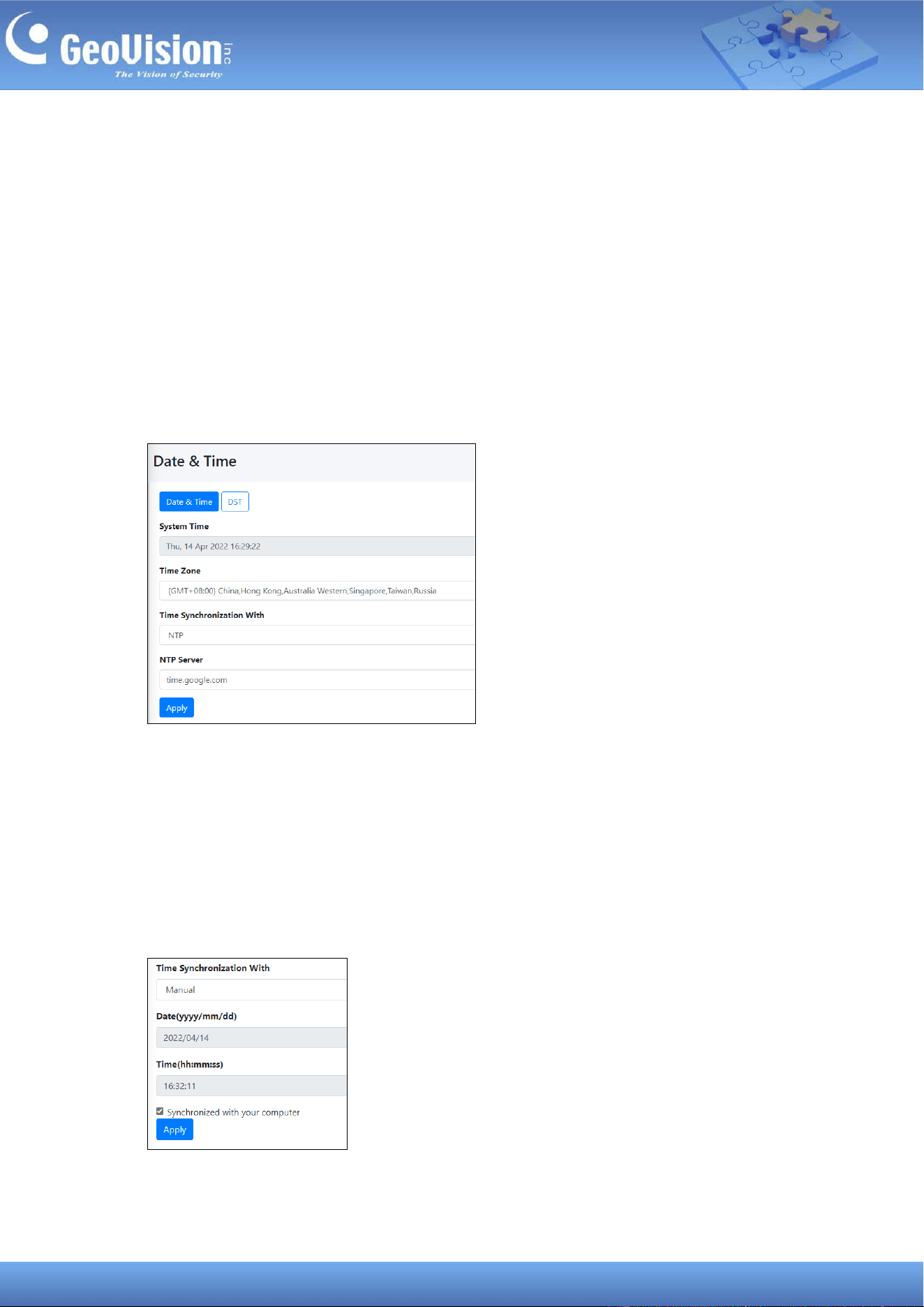
12.4 Date and Time
To configure the date and time of your GV-Cloud Bridge Pro, follow the steps below.
1. In the left menu, click System Settings > Date / Time. This page appears.
2. Select a desired Time Zone.
3. The Time Synchronization With is set to NTP by default. You can change the NTP
server in use by typing another server under NTP Server.
4. To manually set the date and time for your device, select Manual under Time
Synchronization With, and type the desired date and time. Or enable Synchronized
with your computer to sync the device’s date and time with those of the local computer.
48
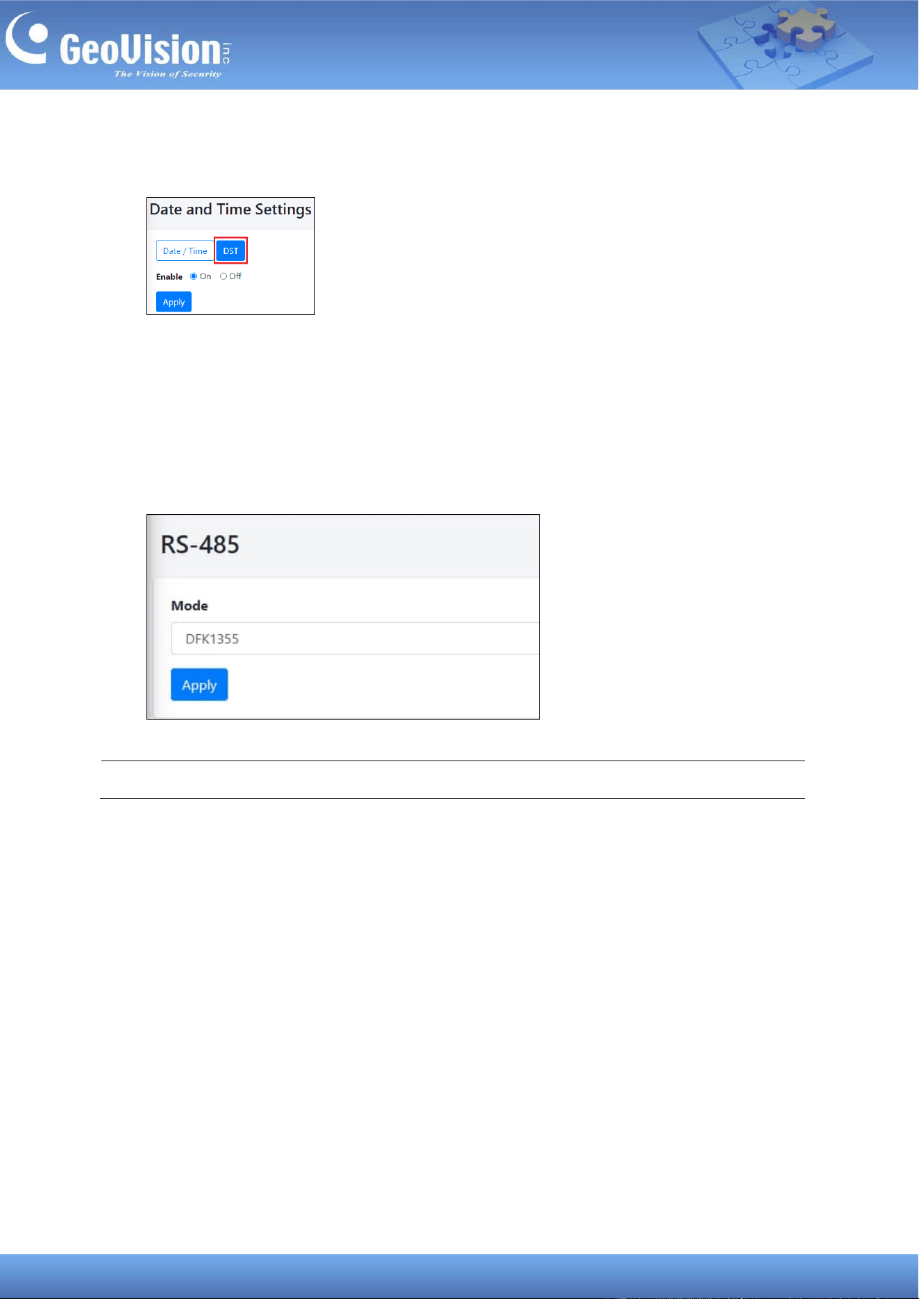
5. Optionally, you can also enable or disable Daylight Saving Time in the DST setting.
12.5 RS-485
Using the RS-485 interface of GV-Cloud Bridge Pro, you can connect up to 8 GV-DFK1355
readers to GV-Cloud Access Control. In the left menu, select System Settings > RS-485, and
select DFK1355 as Mode. Click Apply.
Note: The MPPT / SRNE mode does not function currently.
49
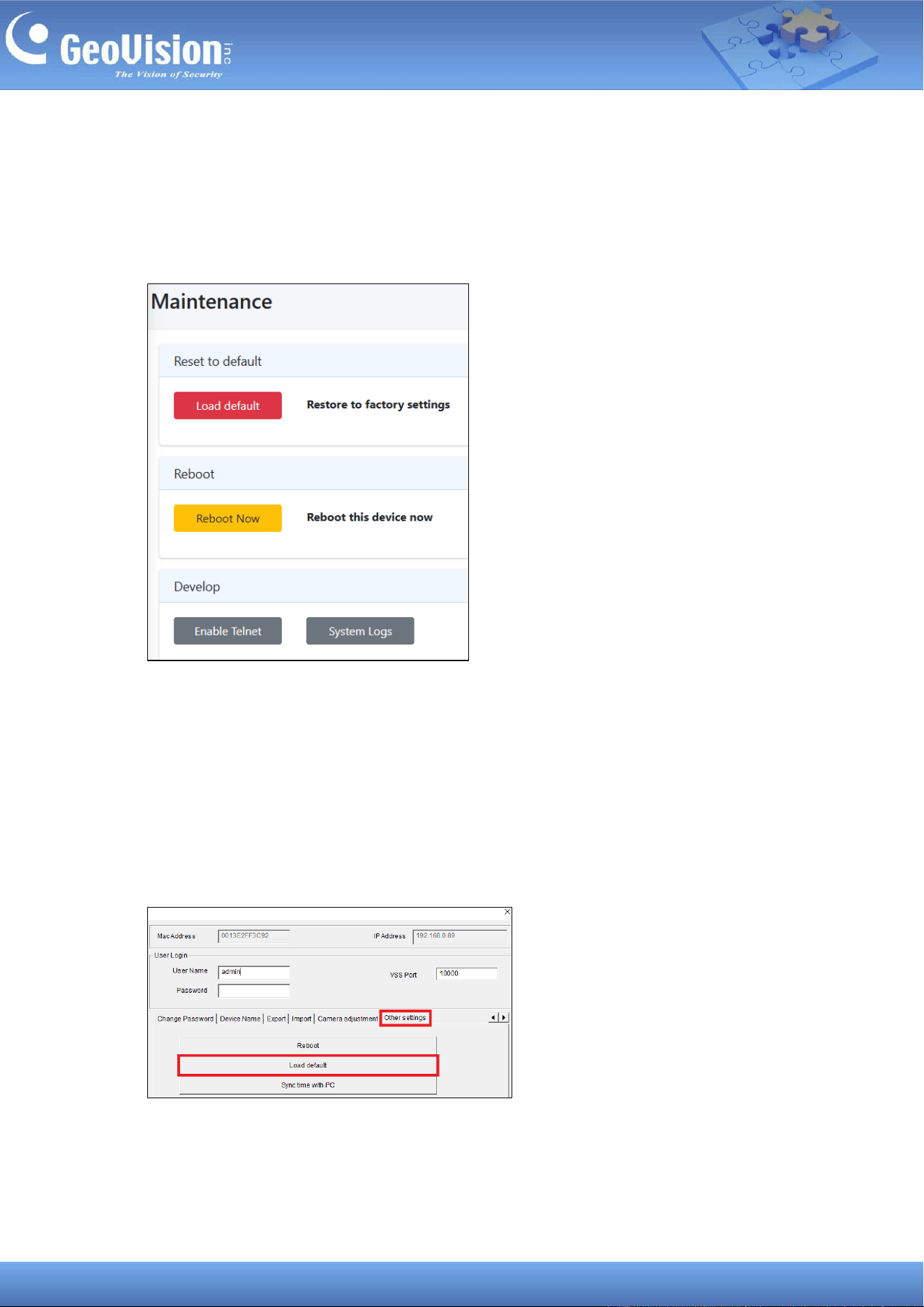
12.6 Maintenance
If GV-Cloud Bridge Pro is not functioning properly, you can reboot it or restore it to factory
default settings. The Develop functions allow technicians to fix problems.
You can also use the following two methods to load default settings for GV-Cloud Bridge Pro:
1. On the device: Press and hold the Default button (No. 5, 1.3 Overview) for 10 ~ 15
seconds to load the default.
2. GV-IP Device Utility: Using the utility to locate your GV-Cloud Bridge Pro, click its IP
address, and select Configure. On the popup dialog box, click the Other settings tab,
type the User Name and Password of the GV-Cloud Bridge Pro, and then click Load
default.
50
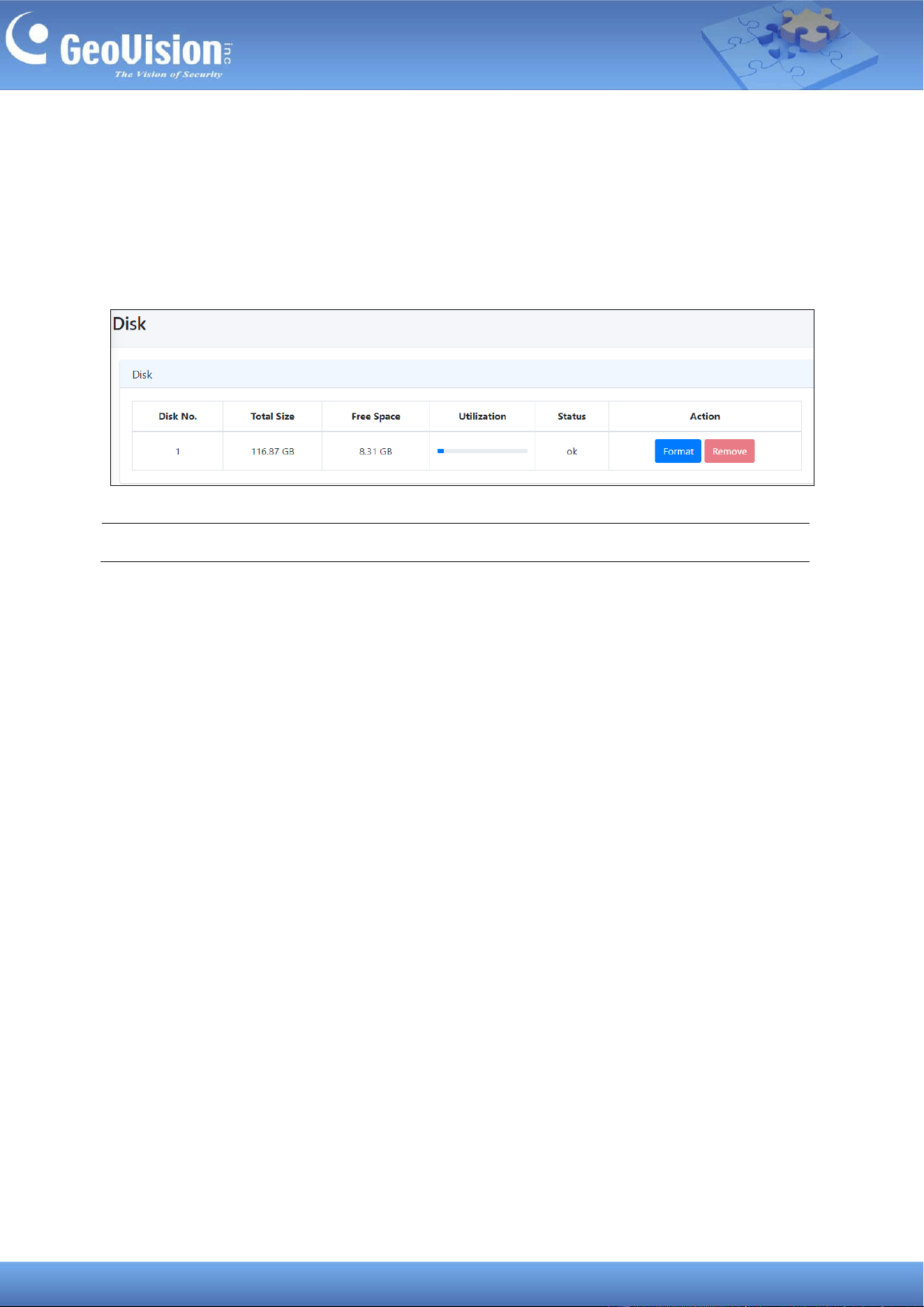
13 Storage
When you insert a memory card or an SSD into GV-Cloud Bridge Pro, utilize the Disk page to
format it. The page will display the current storage space status.
To access the page, in the left menu, click Storage > Disk.
Note: If both a SSD and memory card are attached, the device will only recognize the SSD.
51
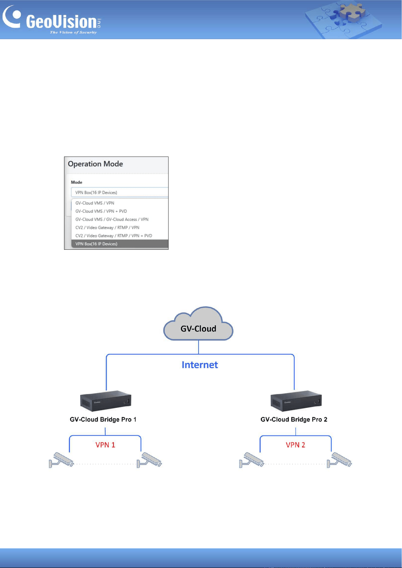
14 VPN
The VPN function of GV-Cloud Bridge Pro allows users to create a virtual private network for
devices on the same LAN, eliminating the need for port forwarding.
The VPN capability is enabled in all operating modes, and you can select a specific VPN Box
operation mode. The VPN function in each operation mode supports up to 8 IP devices,
while the particular VPN Box operation mode allows up to 16 IP devices.
The VPN Box operation mode topology, which supports up to 16 IP devices, is shown below.
IP devices are not restricted to IP cameras. Any network gadget, e.g. GV-IP Decoder Box,
GV-I/O Box or IP speaker, can function.
GV-Cloud Bridge Pro 1
X 16 X 16
52
The following sections introduce the VPN setup procedures for enabling the VPN function in
GV-Cloud Bridge Pro:
• Step 1: Sign up on GV-Cloud
• Step 2: Create a VPN account on GV-Cloud
• Step 3: Connect GV-Cloud Bridge Pro to the VPN account on GV-Cloud
• Step 4: Map the IP addresses from IP devices to VPN IP addresses
Note:
1. The VPN function is not limited to IP cameras. Any network gadgets can connect.
2. To maintain a steady connection, make sure the total bandwidth of 16 IP devices does
not exceed 80 Mbps.
3. The VPN function in the following two operation modes only supports IP device
configuration, not video streaming: (1) GV-Cloud VMS / VPN + PVD, (2) GV-Cloud
Access Control / VPN.
53
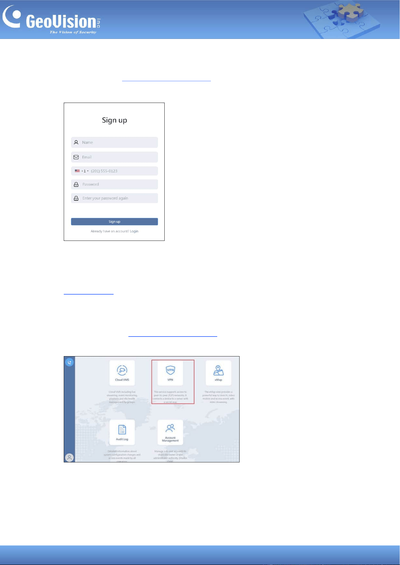
Step 1. Sign up on GV-Cloud
1. Visit GV-Cloud at https://www.gvaicloud.com/ and click Sign up.
2. Type the necessary information and complete the sign-up procedure.
3. Confirm the account by clicking the activation link sent via e-mail. Keep the attached
registration information for logging in GV-Cloud later. For details, see Chapter 1 in
GV-VPN Guide.
Step 2. Create a VPN account on GV-Cloud
4. Log in GV-Cloud at https://www.gvaicloud.com/ using the information created at Step 3.
5. Select VPN.
54
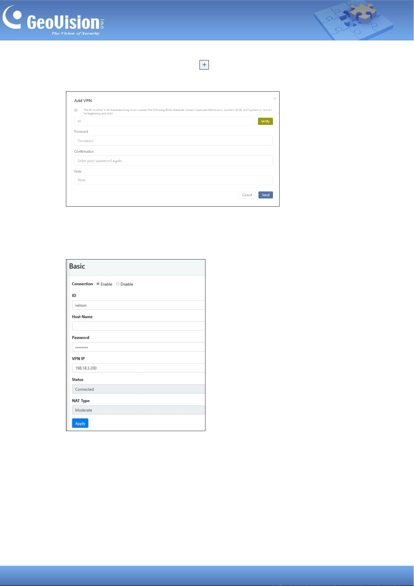
6. On the VPN setup page, click the Add button and type the necessary information to
create a VPN account.
Step 3. Connect GV-Cloud Bridge Pro to the VPN account on GV-Cloud
7. On the GV-Cloud Bridge Pro Web interface, go to GV-VPN > Basic.
8. Enable the connection and give a Host Name to the setting.
9. To connect to the VPN account on GV-Cloud, type the ID and Password created at Step
6
10. To configure a VPN IP for your GV-Cloud Bridge Pro, type a VPN IP ranging from
198.18.0.1 to 198.18.255.254.
11. Click Apply. Once connected, the Status will display “Connected”.
55
Note: Depending on your network setup, you will see the following NAT types: Moderate /
Restrict / Exceed limit / Unknown. For more details, see No.8, 3. Configuring GV-VPN on
GV-VPN Guide.
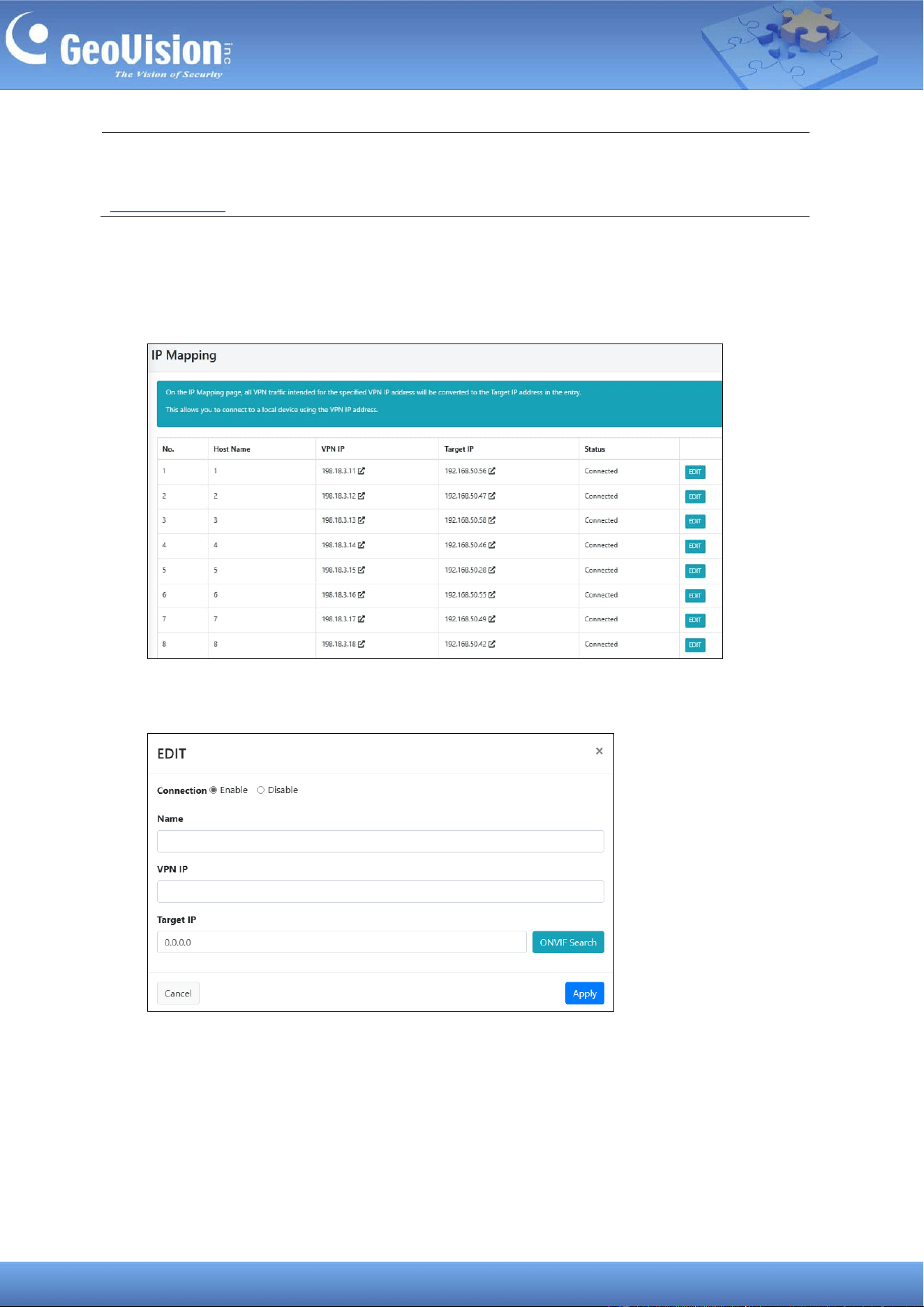
Step 4. Map the IP addresses of IP devices to VPN IP addresses
12. In the left menu, select GV-VPN > IP Mapping.
13. To map a VPN IP to a device, click Edit. This page appears.
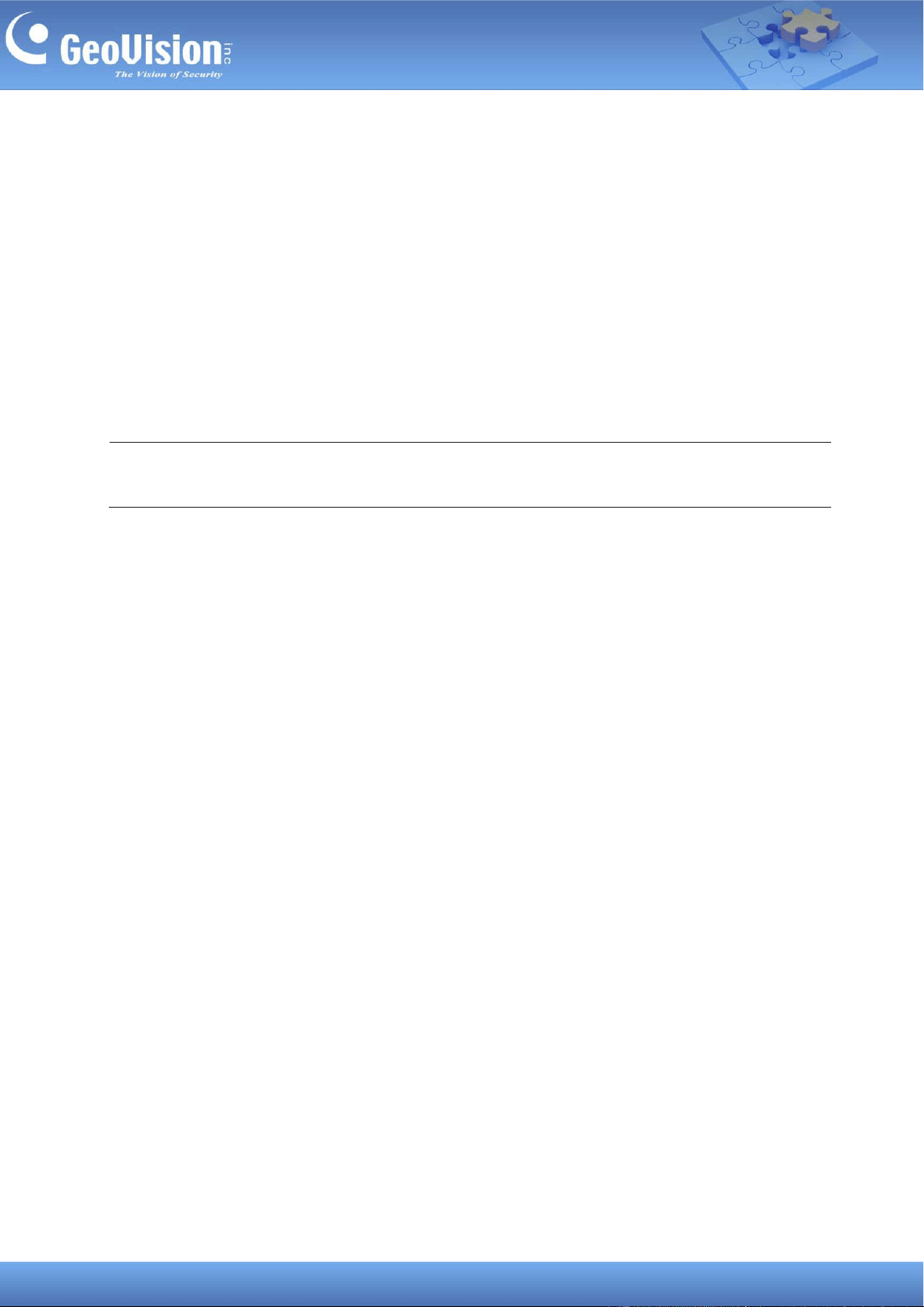
56
14. Enable the connection and give a Name to the setting.
15. To configure a VPN IP for the device, type a VPN IP ranging from 198.18.0.1 to
198.18.255.254 and the device’s IP (Target IP).
16. For the device’s IP, optionally click ONVIF Search to search for the device, and click
Import to automatically fill in the device’s IP on the Edit page.
17. Click Apply.
The Host Name, VPN IP, and Target IP are displayed on each device entry. Once connected,
the Status will display “Connected”.
Note: Make sure the VPN IP address for GV-Cloud Bridge Pro and other devices does not
repeat.
57
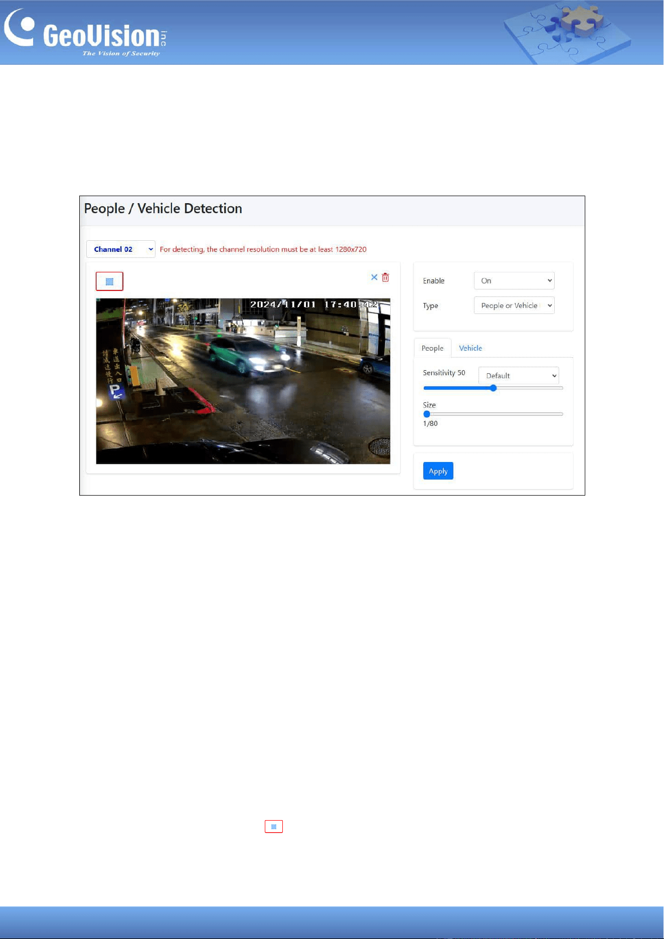
15 People and Vehicle Detection (PVD)
GV-Cloud Bridge Pro can only detect people or vehicle in order to reduce false alarms. Up to
4 channels are supported. To access the page, select Intelligent in the left menu.
1. On the left menu, select Intelligent > People > Vehicle Detection.
2. Select a channel number.
3. Complete the following options on the left side of the user interface:
◼ Enable: Select On to enable the detection.
◼ Type: Select one of the following detection types: People Detection, Vehicle
Detection, People and/or Vehicle Detection.
◼ Sensitivity: Select Default, Low False Alarm or Custom for different sensitivity
parameters: Default is 50 and Low False Alarm is 30. A higher sensitivity
parameter implies that the device is less strict in detecting objects, leading in more
events, a lower likelihood of persons and vehicles, and fewer chances of missing
detection, and vice versa. To set different parameters, switch the People and
Vehicle tabs.
◼ Size: Set the detection size for people or vehicles. When the object is smaller than
the set size, it will not be detected. You can switch the People and Vehicle tabs to
set different parameters.
4. Click the Mask Region icon and draw an area on the image where motion will be
not be detected.
5. Click Apply.
58
Note: The ratio for the minimum object size to the video image is 1/80 for both People and
Vehicle detection. For example, for the video image that is set to 1920 x 1080, the minimum
object size should be 24 x 24 pixels.
59
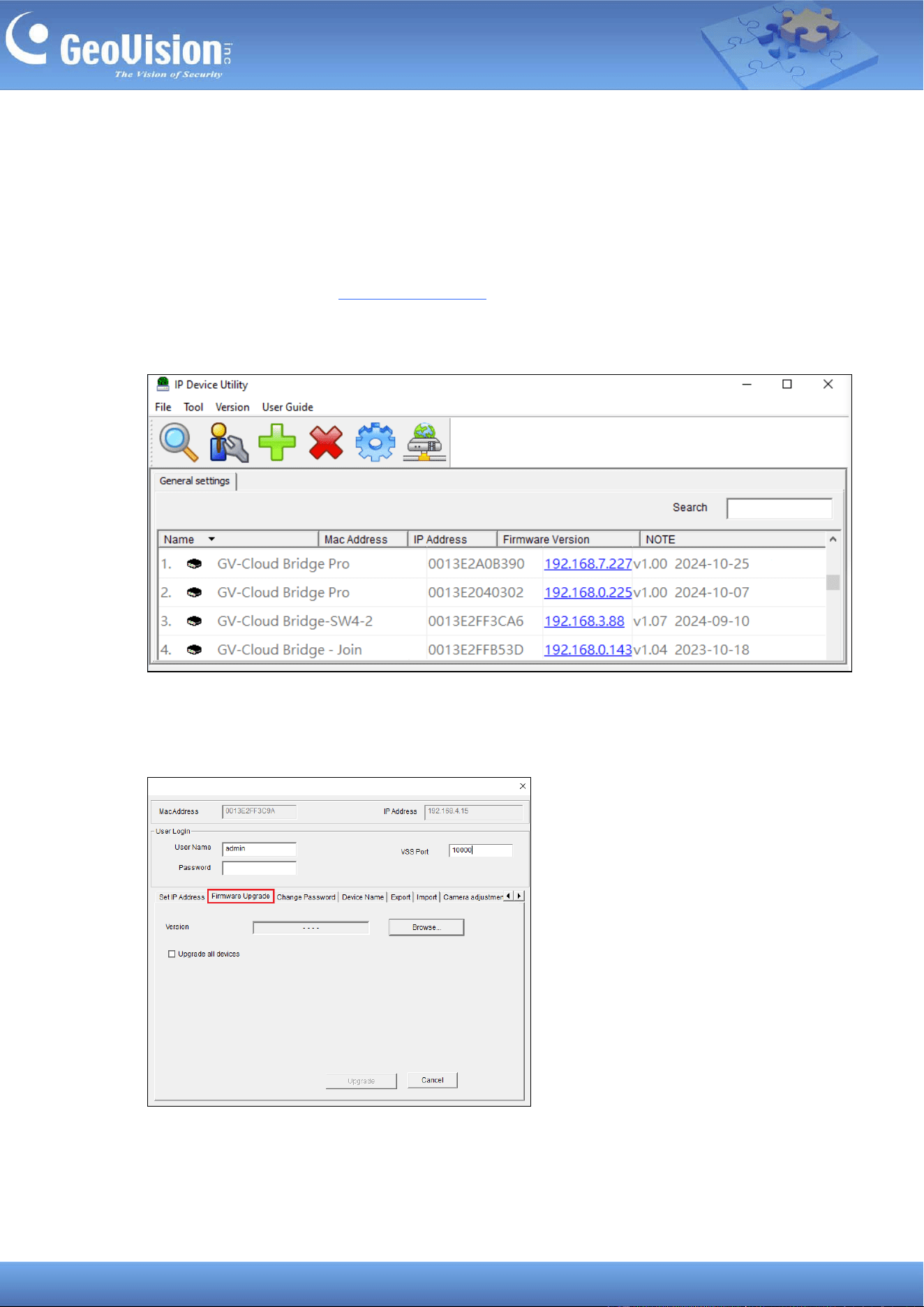
16 Firmware Upgrade
The GV-Cloud Bridge Pro firmware can only be upgraded using GV-IP Device Utility. To
upgrade the firmware, follow the steps below.
1. Download and install the GV-IP Device Utility.
2. Locate your GV-Cloud Bridge Pro on the GV-IP Device Utility window, click its IP address,
and select Configure.
3. On the popup dialog box, click the Firmware Upgrade tab, and click Browse to locate
the firmware file (.img) saved at your local computer.
4. Type the User Name and Password of the ROOT or Admin account. Click Upgrade.
60
© 2025 GeoVision, Inc. All rights reserved.
Scan the following QR codes for product warranty and technical support policy:
[Warranty] [Technical Support Policy]