Plumbing the eFlux DC Flow pump
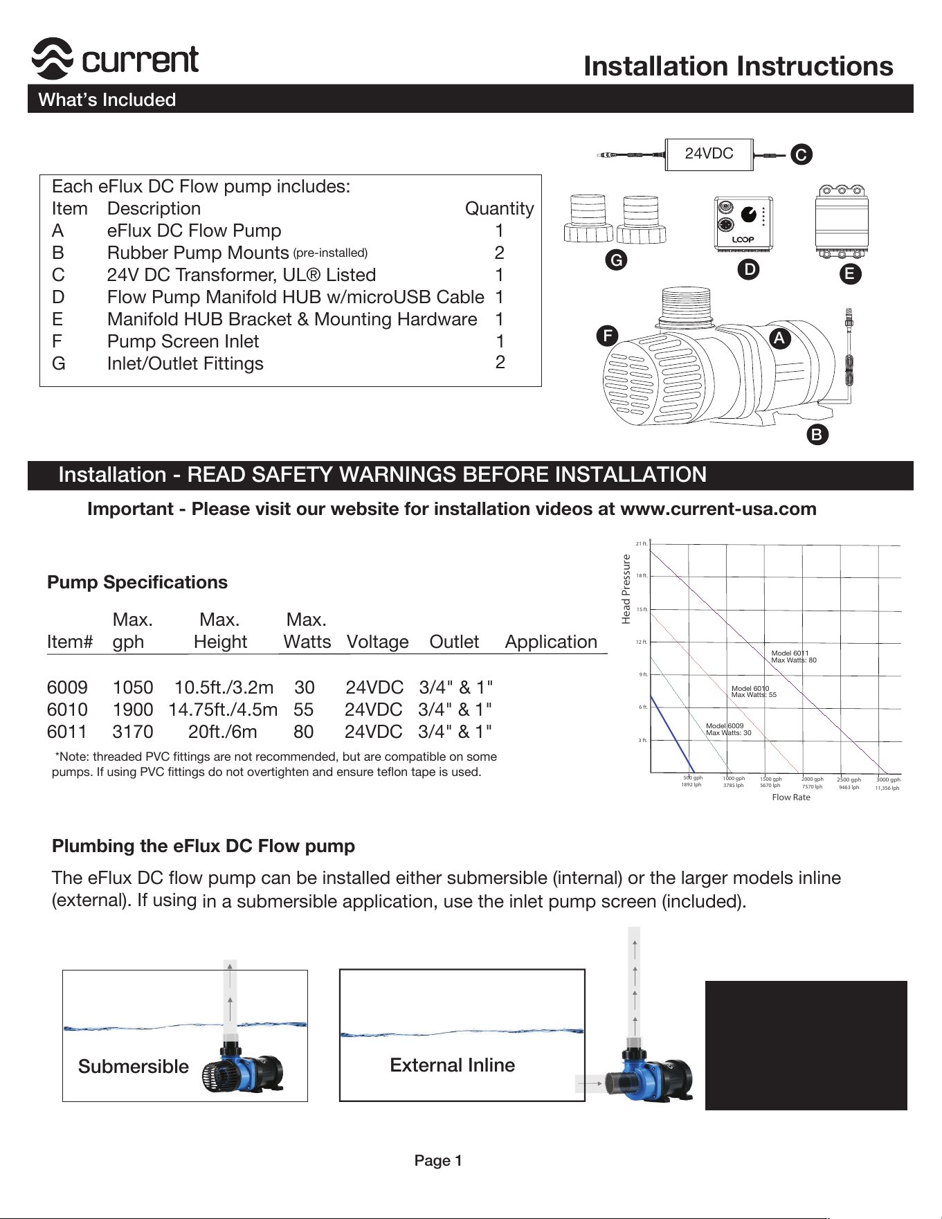
*Note: threaded PVC fittings are not recommended, but are compatible on some
pumps. If using PVC fittings do not overtighten and ensure teflon tape is used.
Installation - READ SAFETY WARNINGS BEFORE INSTALLATION
Each eFlux DC Flow pump includes:
Item Description Quantity
A eFlux DC Flow Pump 1
B Rubber Pump Mounts
(pre-installed)
2
C 24V DC Transformer, UL® Listed 1
D Flow Pump Manifold HUB w/microUSB Cable 1
E Manifold HUB Bracket & Mounting Hardware 1
C
A
B
D
E
24VDC
Installation Instructions
What’s Included
Page 1
F Pump Screen Inlet
G Inlet/Outlet Fittings
1
2
F
G
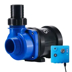
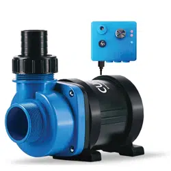
The eFlux DC flow pump can be installed either submersible (internal) or the larger models inline
(external). If using
in a submersible application, use the inlet pump screen (included).
Important - Please visit our website for installation videos at www.current-usa.com
Submersible
External Inline
Pump Specifications
3 ft.
6 ft.
9 ft.
12 ft.
15 ft.
18 ft.
500 gph
1000 gph
1500 gph
2000 gph
3000 gph
2500 gph
21 ft.
Model 6011
Max Watts: 80
Head Pressure
Flow Rate
1892 lph
3785 lph
5670 lph
7570 lph
9463 lph
11,356 lph
Model 6010
Max Watts: 55
Model 6009
Max Watts: 30
Max. Max. Max.
Item# gph Height Watts Voltage Outlet Application
6009 1050 10.5ft./3.2m 30 24VDC 3/4" & 1"
6010 1900 14.75ft./4.5m 55 24VDC 3/4" & 1"
6011 3170 20ft./6m 80 24VDC 3/4" & 1"
6008 520 7.2ft./2.2m 20 24VDC ½" & ¾"
Submerse Only
Submerse/External
Submerse/External
Submerse/External
Note: 6008 is for submersible
applications ONLY.
6009/6010/6011 can be used
both submersible or external.
1
2
3
3
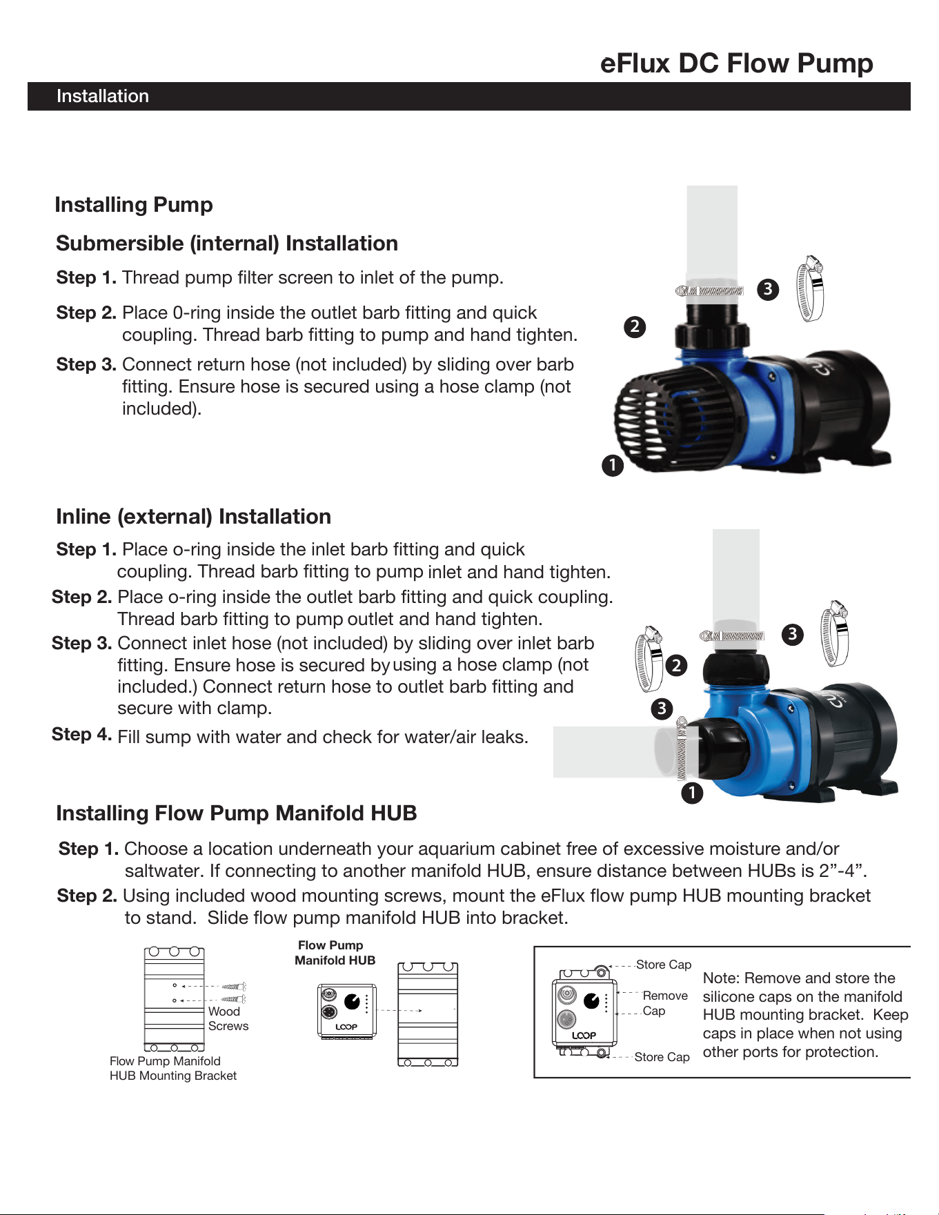
Step 1. Thread pump filter screen to inlet of the pump.
Installing Pump
eFlux DC Flow Pump
Installation
Step 2. Place 0-ring inside the outlet barb fitting and quick
coupling. Thread barb fitting to pump and hand tighten.
Submersible (internal) Installation
Step 3. Connect return hose (not included) by sliding over barb
fitting. Ensure hose is secured using a hose clamp (not
included).
Step 2. Place o-ring inside the outlet barb fitting and quick coupling.
Thread barb fitting to pump outlet and hand tighten.
Inline (external) Installation
Step 3. Connect inlet hose (not included) by sliding over inlet barb
fitting. Ensure hose is secured by
using a hose clamp (not
secure with clamp.
Step 1. Place o-ring inside the inlet barb fitting and quick
coupling. Thread barb fitting to pump
inlet and hand tighten.
Step 4.
Fill sump with water and check for water/air leaks.
1
2
3
included.) Connect return hose to outlet barb fitting and
Installing Flow Pump Manifold HUB
Step 1. Choose a location underneath your aquarium cabinet free of excessive moisture and/or
saltwater. If connecting to another manifold HUB, ensure distance between HUBs is 2”-4”.
Step 2. Using included wood mounting screws, mount the eFlux flow pump HUB mounting bracket
to stand. Slide flow pump manifold HUB into bracket.
Remove
Cap
Store Cap
Store Cap
Wood
Screws
Flow Pump Manifold
HUB Mounting Bracket
Note: Remove and store the
silicone caps on the manifold
HUB mounting bracket. Keep
caps in place when not using
other ports for protection.
Flow Pump
Manifold HUB
Page 2
Step 4.
Fill sump with water and check for water/air leaks.
NOTE: Please ensure to follow your aquarium tank and sump/filter manufacturer instructions
regarding the minimum size requirement of your sump and if a check valve is required.
Pump Maintenance
Installation Instructions
Installation
Page 3
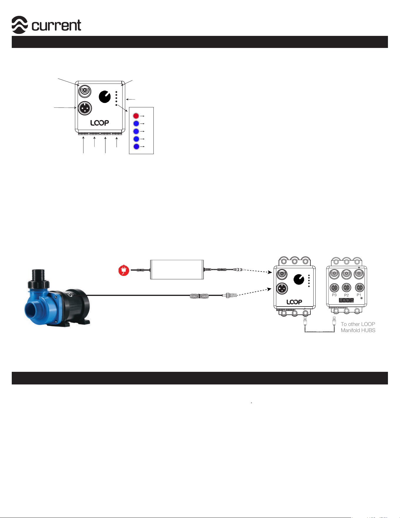
Step 1. Plug DC pump cable into pump connection on manifold HUB.
Step 2. Plug 24VDC power supply into DC input on manifold HUB.
Connecting Pump to Manifold HUB
Step 3. Red LED status light should turn solid red. Adjust flow from 0-100% using dial until
flow rate is acheived. NOTE: eFlux DC pumps have a slow ramp to speed, allow pump
to run for 10-15 seconds for pump to reach adjusted flow.
**Important - Due to harsh conditions found around marine aquariums, it is important to perform the
following pump maintenance every 6 months. When performing any maintenance or service, ensure
pump is disconnected from power and manifold HUB.
1. Remove pump from service by disconnecting power and removing pump from sump via disconnect
fittings.
2. Carefully remove front pump cover, o-rings and slide impeller from pump. Use a small soft brush and
running freshwater to clean any organic debris. If any calcium deposits have developed, soak the
components in mild citric acid/freshwater solution. DO NOT use strong acids or vinegar.
3. Re-assemble pump, reconnect fittings with all o-rings properly in place and reconnect power.
Flow Pump
Manifold HUB
P1
Pump Dial
Flow Control
Pump Power
DC Input
Pump
Connection
Port#1
Port#2
Port#3
Port#4
Important: Before connecting all of the components together, please review the following specifications
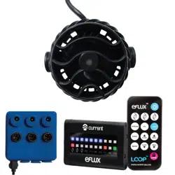
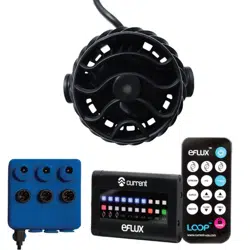
in regards to the Flow Pump Manifold HUB and appropriate connections.
Communication LED
Indicator Lights
Specifications:
Pump DC Inputs:
Voltage: 24VDC
Indicator LEDs:
A (Blue)= Indicates 520/1050 gph pump is connected
B (Blue)= Indicates 1900 gph pump is connected
C (Blue)= Indicates 3170 gph pump is connected
D (Blue)= Feed - flashes when pump is in feed mode
E (Red)= Active feedback/pump status:
Red Solid - indicates pump is operating normal
Red Flashing - indicates non-normal operation
(pump running dry, over voltage/under voltage, over temp)
MicroUSB Ports
(all for communication)
!
"
#
$
%
AC Power
GFCI Outlet
24VDC
Transformer
Flow Pump
Manifold HUB
Connect to Pump Input
Connect to DC Input
To other LOOP
Manifold HUBS
P1
P3
P2
Note: FEED mode will only operate when DC pump is plugged into a manifold HUB with an Orbit IC
controller, eFlux wave pump controller or the HUB is controlled via Bluetooth. When in FEED
mode, DC flow pump will ramp down to 30% flow for 10 minutes, then ramp to normal speed.
D
C
Do not install pumps where strong currents can harm animals. Do
not install close to sand bed where it can suck/stir sand.
Keep magnets and all accessories out of reach of children.
Never place magnets or pump near sensitive electronics, sharp
objects or other attractive surfaces.
Do not run pumps dry or out of water.
Always place spacer between magnets when not in use.
Always unplug with dry hands for maintenance or servicing.
Turn all controllers OFF and disconnect power supply before
performing any service or maintenance.
This product MUST be powered by a UL or ETL listed power supply.
To avoid possible electric shock, power supply MUST be plugged
into a GFCI wall outlet installed by a certified electrician in
accordance with all local codes. All products must have a drip loop.
This product MUST be purchased from an authorized Current-USA
reseller. Visit our website for a list of unauthorized resellers.
Current USA, Inc. warrants this product against defects in
materials and worksmanship for ONE (1) YEAR from the date of
original retail purchase and is not transferable.
Current-USA One Year Limited Warranty
a pump
taking o
from GFCI.
GFCI Outlet
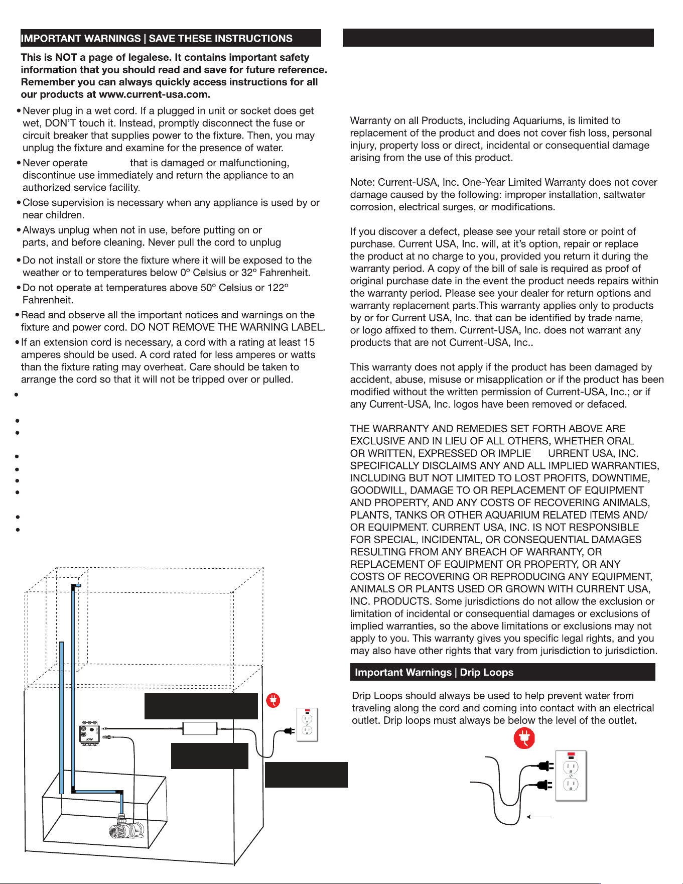
Drip
Loop
AC Power
GFCI Outlet
24VDC
Power Supply
DC Flow Pump
Manifold HUB
eFlux DC
Flow Pump
Ensure use of drip
loop for all cables
Use only with GFCI
Protected AC Outlet
Ensure correct voltage power
supply for each component
Page 4