WARNING
WARNING
WARNING
WARNING
WARNING
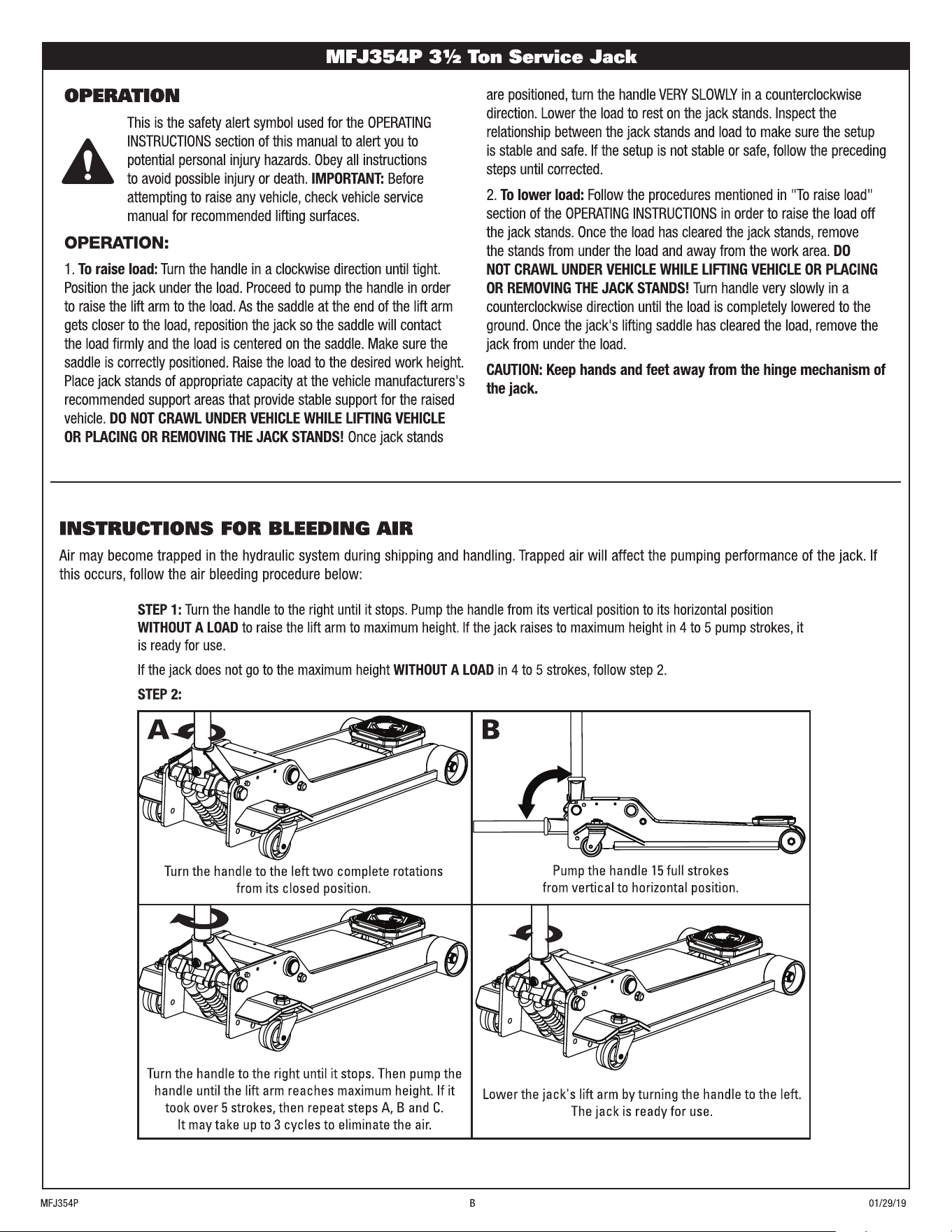
2 X
C
D
15 X
Important: Service jacks are self-contained devices used for lifting, but not sustaining, a partial vehicular load. In accordance with ASME-PASE
Load Sustaining Test: “A load not less than the rated capacity…shall not lower more than 1/8" (3.18mm) in the first minute, nor a total of .1875"
(4.76mm) in 10 minutes.” Lowering within this range is considered normal operation and is NOT a warrantable defect.
PROBLEM ACTION
1. Unit will not lift rated load. Purge air from hydraulic system by following procedure under SETUP.
2. Unit will not sustain rated load or feels “spongy” under rated load. Purge air from hydraulic system as above.
3. Unit will not lift to full height. Purge air from hydraulic system as above.
4. Unit will not lower completely. Check oil level. Make sure hydraulic system is not overfilled.
5. Handle tends to raise up while the unit is under rated load. Pump the handle rapidly several times to push oil past ball valves in power unit.
6. Unit still does not operate. Contact customer service.
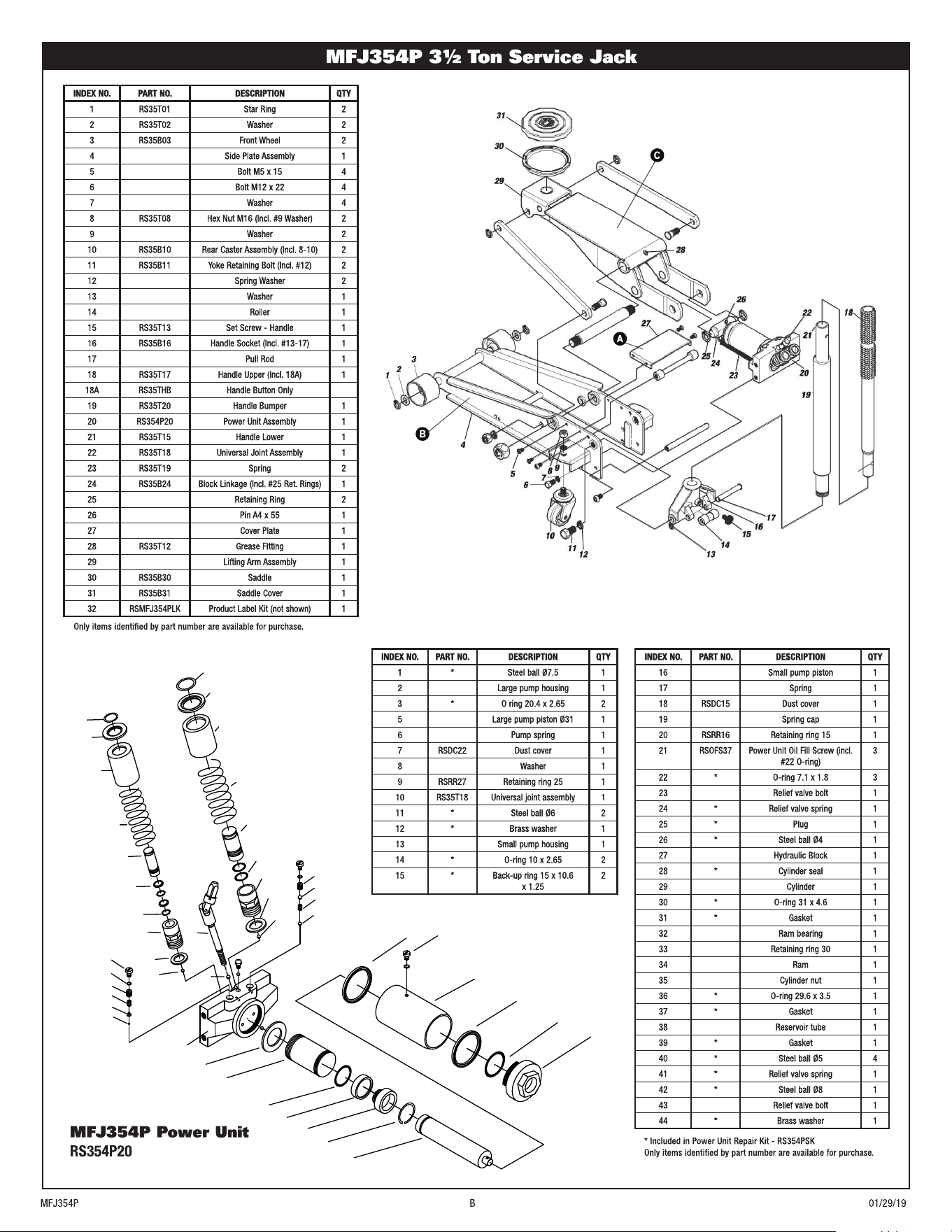
INDEX NO. PART NO. DESCRIPTION QTY
1 RS35T01 Star Ring 2
2 RS35T02 Washer 2
3 RS35B03 Front Wheel 2
4 Side Plate Assembly 1
5 Bolt M5 x 15 4
6 Bolt M12 x 22 4
7 Washer 4
8 RS35T08 Hex Nut M16 (Incl. #9 Washer) 2
9 Washer 2
10 RS35B10 Rear Caster Assembly (Incl. 8-10) 2
11 RS35B11 Yoke Retaining Bolt (Incl. #12) 2
12 Spring Washer 2
13 Washer 1
14 Roller 1
15 RS35T13 Set Screw - Handle 1
16 RS35B16 Handle Socket (Incl. #13-17) 1
17 Pull Rod 1
18 RS35T17 Handle Upper (Incl. 18A) 1
18A RS35THB Handle Button Only
19 RS35T20 Handle Bumper 1
20 RS354P20 Power Unit Assembly 1
21 RS35T15 Handle Lower 1
22 RS35T18 Universal Joint Assembly 1
23 RS35T19 Spring 2
24 RS35B24 Block Linkage (Incl. #25 Ret. Rings) 1
25 Retaining Ring 2
26 Pin A4 x 55 1
27 Cover Plate 1
28 RS35T12 Grease Fitting 1
29 Lifting Arm Assembly 1
30 RS35B30 Saddle 1
31 RS35B31 Saddle Cover 1
32 RSMFJ354PLK Product Label Kit (not shown) 1
44
28
34
30
32
33
31
29
25
26
23
24
21
22
40
11
27
35
21
36
37
10
13
12
14
11
1
41
38
39
7
20
16
17
18
19
15
43
2
42
3
5
6
8
9
18A
INDEX NO. PART NO. DESCRIPTION QTY
16 Small pump piston 1
17 Spring 1
18 RSDC15 Dust cover 1
19 Spring cap 1
20 RSRR16 Retaining ring 15 1
21 RSOFS37 Power Unit Oil Fill Screw (incl.
#22 O-ring)
3
22 * O-ring 7.1 x 1.8 3
23 Relief valve bolt 1
24 * Relief valve spring 1
25 * Plug 1
26 * Steel ball Ø4 1
27 Hydraulic Block 1
28 * Cylinder seal 1
29 Cylinder 1
30 * O-ring 31 x 4.6 1
31 * Gasket 1
32 Ram bearing 1
33 Retaining ring 30 1
34 Ram 1
35 Cylinder nut 1
36 * O-ring 29.6 x 3.5 1
37 * Gasket 1
38 Reservoir tube 1
39 * Gasket 1
40 * Steel ball Ø5 4
41 * Relief valve spring 1
42 * Steel ball Ø8 1
43 Relief valve bolt 1
44 * Brass washer 1
INDEX NO. PART NO. DESCRIPTION QTY
1 * Steel ball Ø7.5 1
2 Large pump housing 1
3 * O ring 20.4 x 2.65 2
5 Large pump piston Ø31 1
6 Pump spring 1
7 RSDC22 Dust cover 1
8 Washer 1
9 RSRR27 Retaining ring 25 1
10 RS35T18 Universal joint assembly 1
11 * Steel ball Ø6 2
12 * Brass washer 1
13 Small pump housing 1
14 * O-ring 10 x 2.65 2
15 * Back-up ring 15 x 10.6
x 1.25
2
ADVERTENCIA
ADVERTENCIA
ADVERTENCIA
ADVERTENCIA
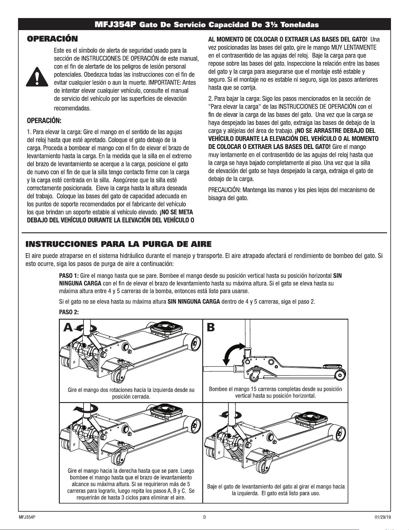
2 X
C
D
15 X
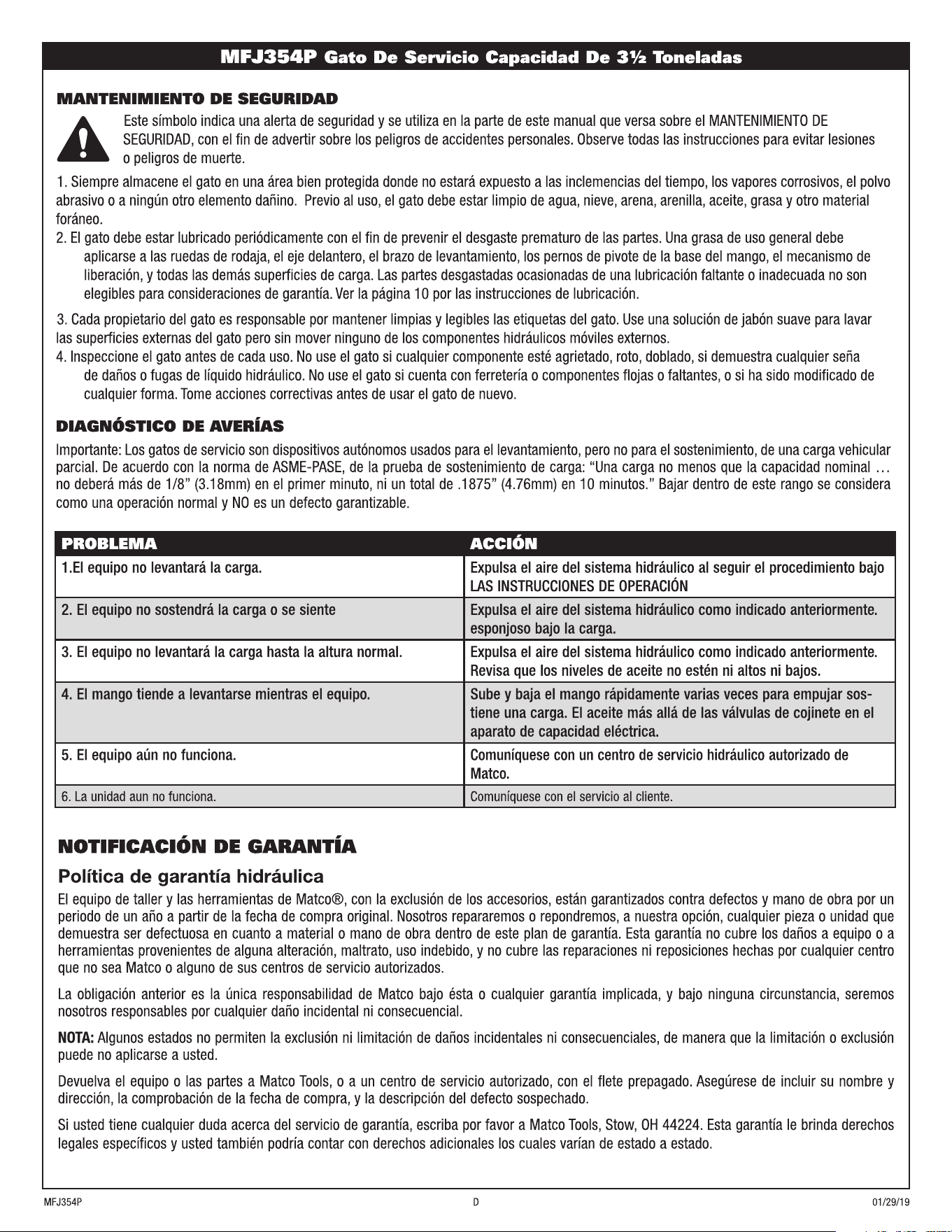
PROBLEMA ACCIÓN
1.El equipo no levantará la carga. Expulsa el aire del sistema hidráulico al seguir el procedimiento bajo
LAS INSTRUCCIONES DE OPERACIÓN
2. El equipo no sostendrá la carga o se siente Expulsa el aire del sistema hidráulico como indicado anteriormente.
esponjoso bajo la carga.
3. El equipo no levantará la carga hasta la altura normal. Expulsa el aire del sistema hidráulico como indicado anteriormente.
Revisa que los niveles de aceite no estén ni altos ni bajos.
4. El mango tiende a levantarse mientras el equipo. Sube y baja el mango rápidamente varias veces para empujar sos-
tiene una carga. El aceite más allá de las válvulas de cojinete en el
aparato de capacidad eléctrica.
5. El equipo aún no funciona.
Comuníquese con un centro de servicio hidráulico autorizado de
Matco.
6. La unidad aun no funciona. Comuníquese con el servicio al cliente.