BLACK
DIC 2181s*
UCAB
Stereo Amplifier
Amplificateur Stéréo
OWNER’S MANUAL
MODE D’EMPLOI

HiFi Began with Yamaha
Yamaha’s involvement with and passion for music goes back
more than a century, to when we built our first reed organ in
1887. Now we are the world’s leading producer of pianos and
other musical instruments, and are involved with music in many
other ways as well. We manufacture professional recording
equipment, we design concert halls and we assist artists at
concerts with set up and sound tuning.
This knowledge and experience benefits our production of
audio components in many ways. We introduced our first HiFi
(High Fidelity) turntable in 1954. Thereafter we were one of the first
to offer mass-produced, high quality audio equipment,
and introduced many legendary stereo components.
We hope you enjoy the genuine HiFi experience of
Yamaha Natural Sound.

Excellence in Audio Achievement
First HiFi System introduced in 1920
We introduced numerous HiFi components
(turntables, FM/AM tuners, integrated
amplifiers, preamplifiers, power amplifiers
and speakers) in 1955 - 1965.
Natural Sound Speaker Series introduced
in 1967
NS-20 Monitor Speaker
CA-1000 Integrated Amplifier
Featuring A-Class operation, the CA-1000 set
the standard for integrated amplifiers.
NS-690 Monitor Speaker
NS-1000M Monitor Speaker
A truly legendary speaker still revered by HiFi
enthusiasts.
B-1 Power Amplifier
An innovative power amp that used FETs in all
stages.
C-2 Control Amplifier
Received top prize at the Milan International Music
and HiFi Show.
NS-10M Studio Monitor Speaker
Became of the most popular studio monitors
in the world.
A-1 Integrated Amplifier
PX-2 Turntable
Yamaha’s first straight arm turntable.
B-6 Power Amplifier
Pyramid-shaped power amplifier.
GT-2000/L Turntable
First CD Player (CD-1) introduced in 1983
B-2x Power Amplifier
MX-10000 Power Amplifier and
CX-10000 Control Amplifier
Redefined the capabilities of separate components.
AX-1 Integrated Amplifier
GT-CD1 CD Player
MX-1 Power Amplifier and
CX-1 Preamplifier
Soavo-1 and Soavo-2 Natural Sound
Speaker Systems
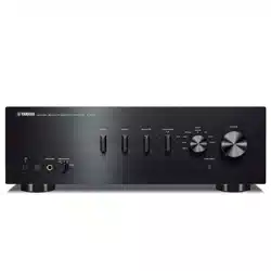
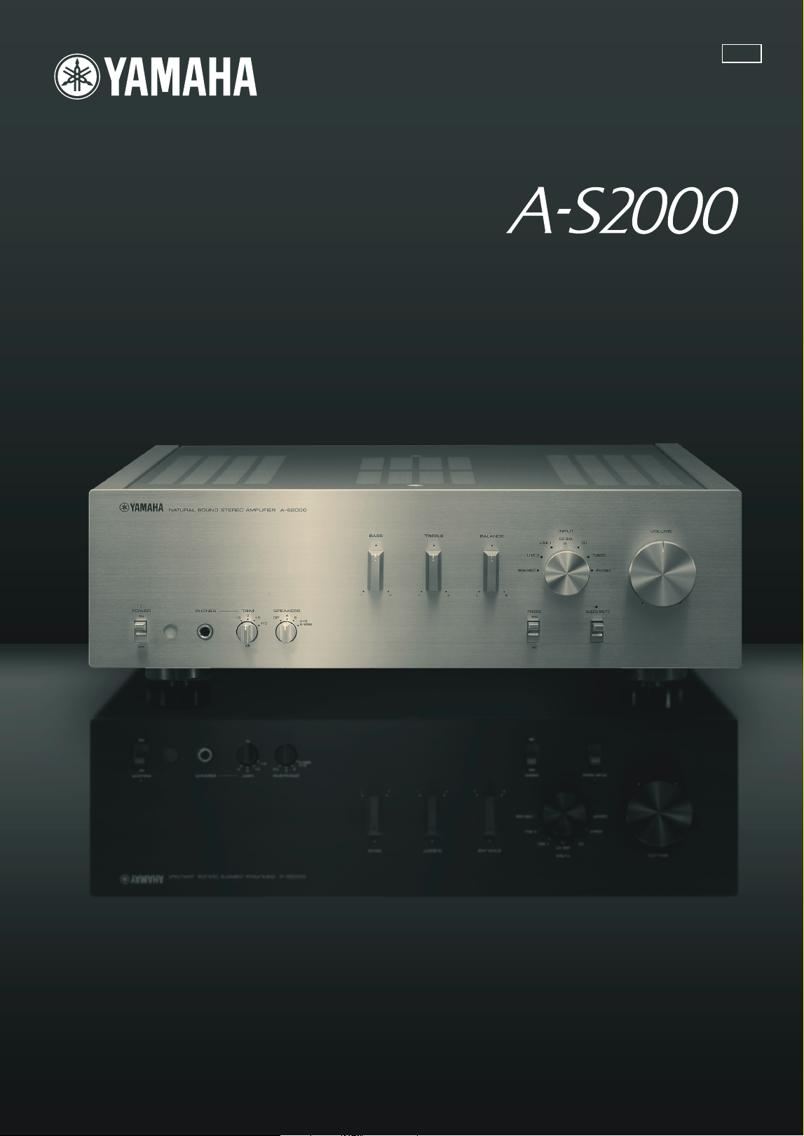
A-S2000 Stereo Amplifier and
CD-S2000 Super Audio CD Player

4 En
◆ Full floating and balanced circuit design achieves for the first time the
full potential of analogue amplification
An entirely new floating and balanced power amp achieves complete symmetry and permits full balanced transmission
(amplification) from the input jack to just before the speaker jack
◆ Full-stage balanced signal transmission
The world’s first integrated amp to offer full stage balanced transmission, combining high power output with good sound
texture and outstanding S/N performance
◆ Floating and balanced power amp
◆ Fully balanced control amp
◆ Fully balanced digital volume and tone controls
◆ Four large capacity power supplies
◆ Symmetrical construction
◆ Headphone amp for low impedance drive
■ Supplied accessories
Please check that you have received all of the following parts.
• Remote control
• Batteries (AA, R6, UM-3) (×2)
• Power cable
• Safety brochure
■ About this manual
• y indicates a tip for your operation.
• This manual is printed prior to production. Design and specifications are subject to change in part as a result of improvements, etc. In
case of differences between the manual and the product, the product has priority.
• The color of images in this manual may vary from the original.
• Read the safety brochure before using this unit.
Contents
Controls and functions.......................................................................................................................................... 6
Connections.......................................................................................................................................................... 14
Specifications ....................................................................................................................................................... 20
Troubleshooting................................................................................................................................................... 24

5 En
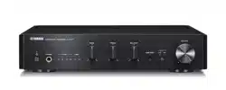
Controls and functions
In this chapter, you will learn the controls and functions of A-S2000.
6 En
Controls and functions
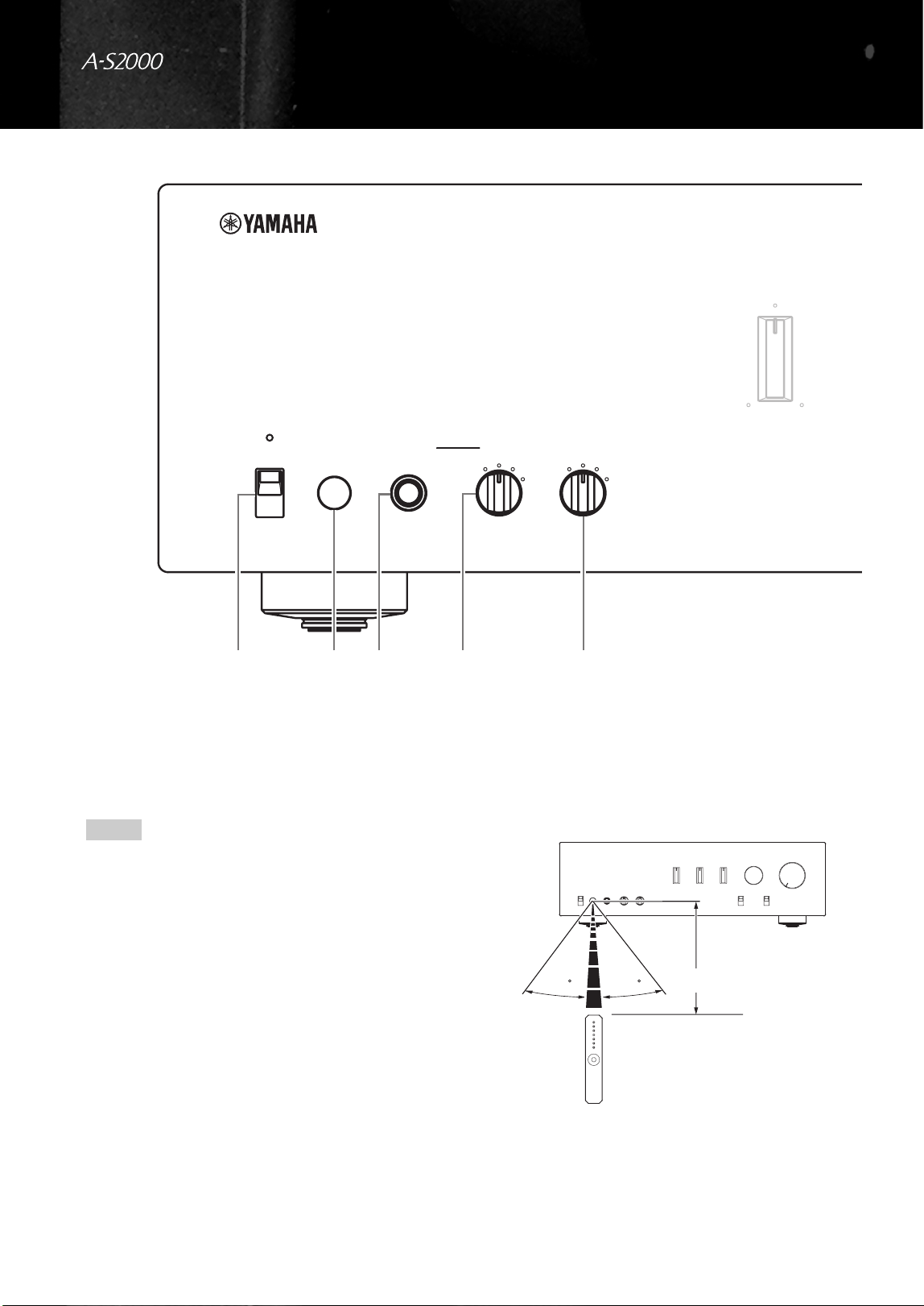
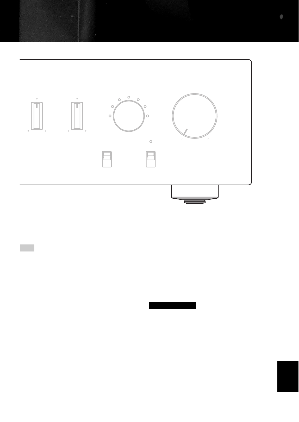
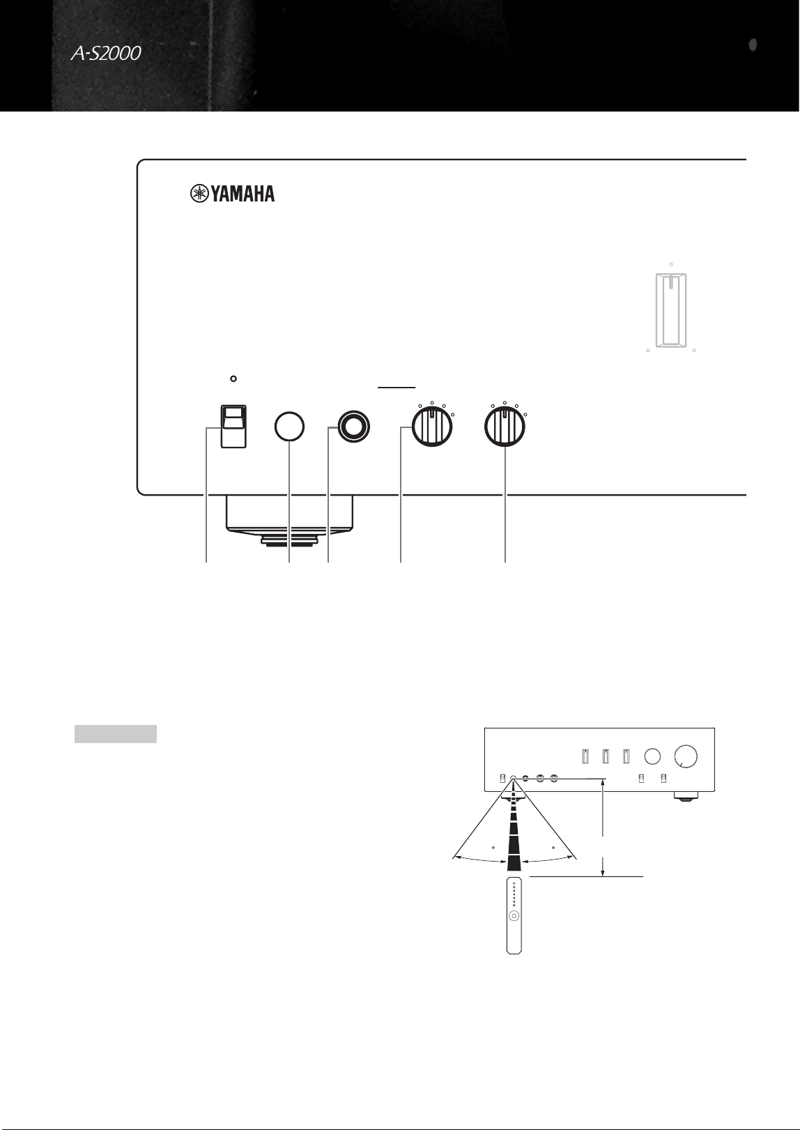
■ Front panel (left side)
1 POWER
Press upward or downward to turn on or off this unit.
y
The POWER indicator above lights up when this unit is turned
on.
• If the POWER indicator flashes when you turn on this unit,
disconnect the AC power cable and contact the nearest
authorized Yamaha dealer or service center (see page 24).
• When you turn on this unit, there will be a few second delay
before this unit can reproduce sound.
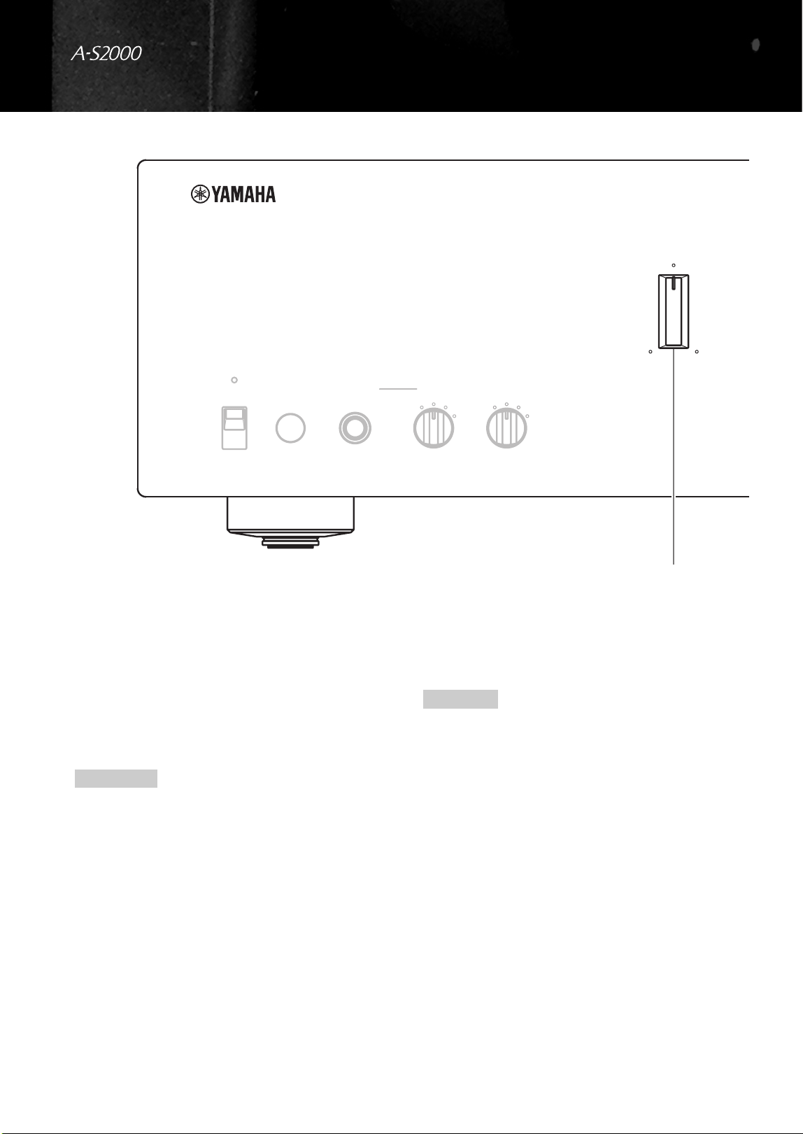
2 Remote control sensor
Receives signals from the remote control.
The remote control transmits a directional infrared beam.
Be sure to aim the remote control directly at the remote
control sensor on the front panel of this unit during
operation.
SPEAKERSTRIMPHONESPOWER
OFF
ON
dB
A
B
A+B
BI-WIRING
0
-6
+6
+12
OFF
BASS
+
-
41325
Notes
30 30
Approximately 6 m (20 ft)
7 En
3 PHONES jack
Outputs audio for private listening with headphones.
When headphones are plugged in:
– Both speaker sets connected to the SPEAKERS L/R CH A
and B terminals are turned off.
– No signals are output at the PRE OUT jacks, while signals are
output at the REC jacks.
– You cannot select MAIN DIRECT as the input source.
– If headphones are plugged into the PHONES jack while
MAIN DIRECT is selected as the input source, no audio is
output at the PHONES jack.
4 TRIM
Adjusts the volume level when headphones are plugged in
to avoid sudden changes in volume.
Choices: –6 dB, 0 dB, +6 dB, +12 dB
5 SPEAKERS
Turns on or off the speaker set connected to the
SPEAKERS L/R CH A and/or B terminals on the rear
panel.
• Switch to the OFF position to turn off both speaker
sets.
• Switch to the A or B position to turn on the speaker set
connected to the SPEAKERS L/R CH A or B
terminals.
• Switch to the A+B BI-WIRING position to turn on
both speaker sets.
If you use two sets (A and B), the impedance of each speaker
must be 8 Ω or higher.
BALANCE
VOLUMEINPUT
TREBLE
MC
MM
MAIN DIRECT
LINE 2
LINE 1
CD BAL
CD
TUNER
PHONO
AUDIO MUTEPHONO
RL+
-
Note
Caution
English
8 En
Controls and functions
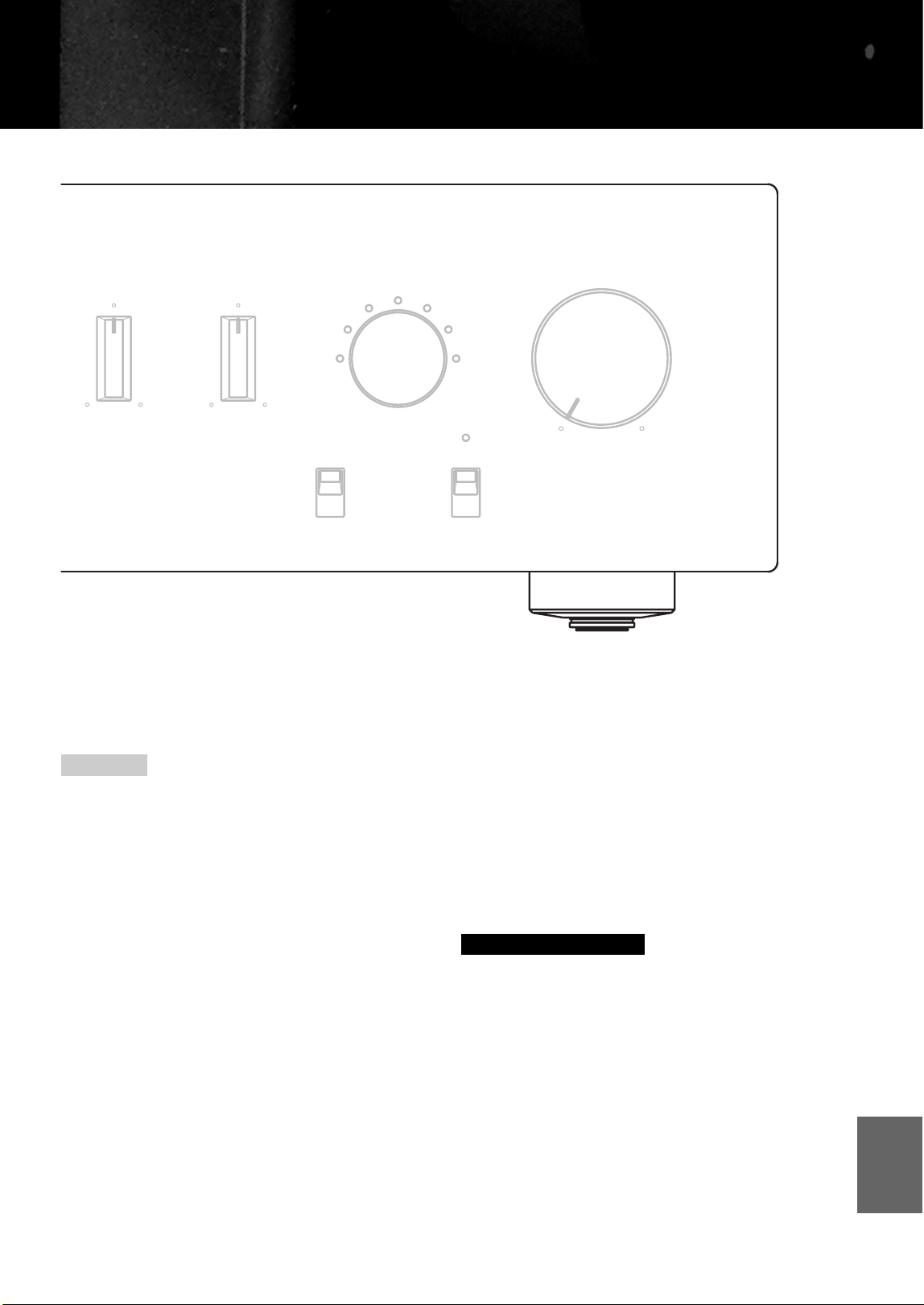
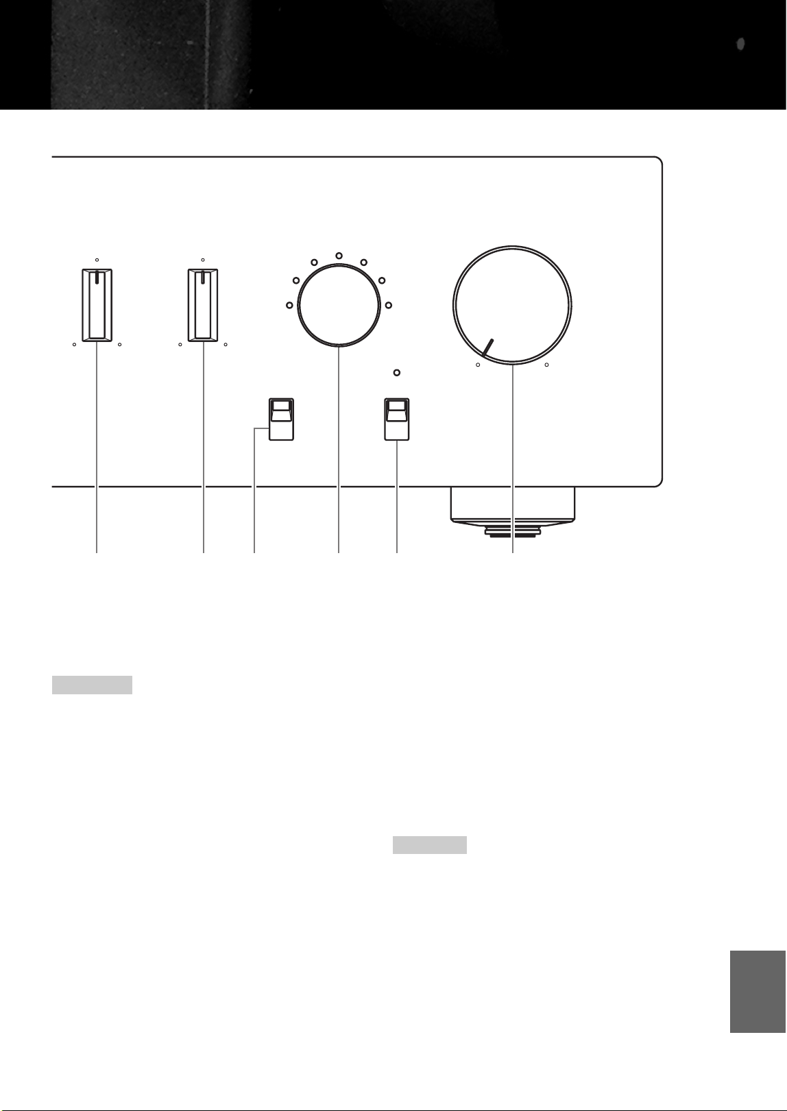
■ Front panel (right side)
6 BASS
Increases or decreases the low frequency response. The 0
position produces a flat response.
Control range: –10 dB to +10 dB
7 TREBLE
Increases or decreases the high frequency response. The 0
position produces a flat response.
Control range: –10 dB to +10 dB
• When both the BASS and TREBLE controls are set to the 0
position, audio signal bypasses the tone control circuitry.
• The BASS and TREBLE controls do not affect the signals input
at the MAIN DIRECT jacks and signals output at the REC OUT
jacks.
8 BALANCE
Adjusts the audio output balance of the left and right
speakers to compensate for sound imbalances caused by
speaker locations or listening room conditions.
The BALANCE control does not affect the signals input at the
MAIN DIRECT jacks and signals output at the REC OUT jacks.
9 PHONO
Selects the type of magnetic cartridge of the turntable
connected to the PHONO jacks on the rear panel.
• Press upward to the MM position when the connected
turntable has a moving magnet (MM) cartridge.
• Press downward to the MC position when the
connected turntable has a moving coil (MC) cartridge.
• When you replace the cartridge, be sure to turn off this
unit.
SPEAKERSTRIMPHONESPOWER
OFF
ON
dB
A
B
A+B
BI-WIRING
0
-6
+6
+12
OFF
BASS
+
-
6
Notes
Note
9 En
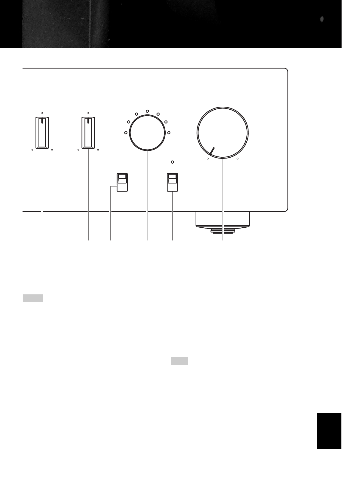
0 INPUT selector
Selects the input source you want to listen to.
The audio signals of the selected input source are also
output at the REC jacks.
• Switch to the CD BAL position to select the CD player
connected to the CD BAL jacks (balanced XLR jacks).
• Switch to the CD position to select the CD player connected to
the CD jacks (unbalanced RCA jacks).
• Switch to the MAIN DIRECT position to select the component
connected to the MAIN IN jacks. When MAIN DIRECT is
selected as the input source, no signals are output at the PRE
OUT, REC, and PHONES jacks.
A AUDIO MUTE
Press downward to reduce the current volume level by
approximately 20 dB. Press again to restore the audio
output to the previous volume level.
y
• The AUDIO MUTE indicator lights up while the mute function
is on.
• You can also rotate VOLUME on the front panel or press
VOL +/– on the remote control to resume the audio output.
B VOLUME
Controls the volume level. This does not affect the REC
level.
The VOLUME control does not affect when you select MAIN
DIRECT as the input source. Adjust the volume level using the
volume control on the external amplifier connected to the MAIN
DIRECT jacks.
BALANCE
VOLUMEINPUT
TREBLE
MC
MM
MAIN DIRECT
LINE 2
LINE 1
CD BAL
CD
TUNER
PHONO
AUDIO MUTEPHONO
RL+
-
BA9087
Notes
Note
English

10 En
Controls and functions
■ Rear panel
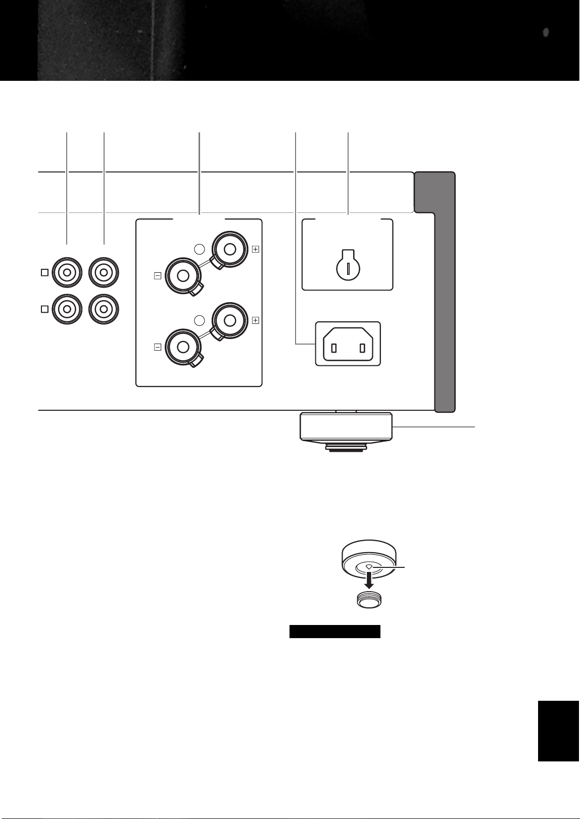
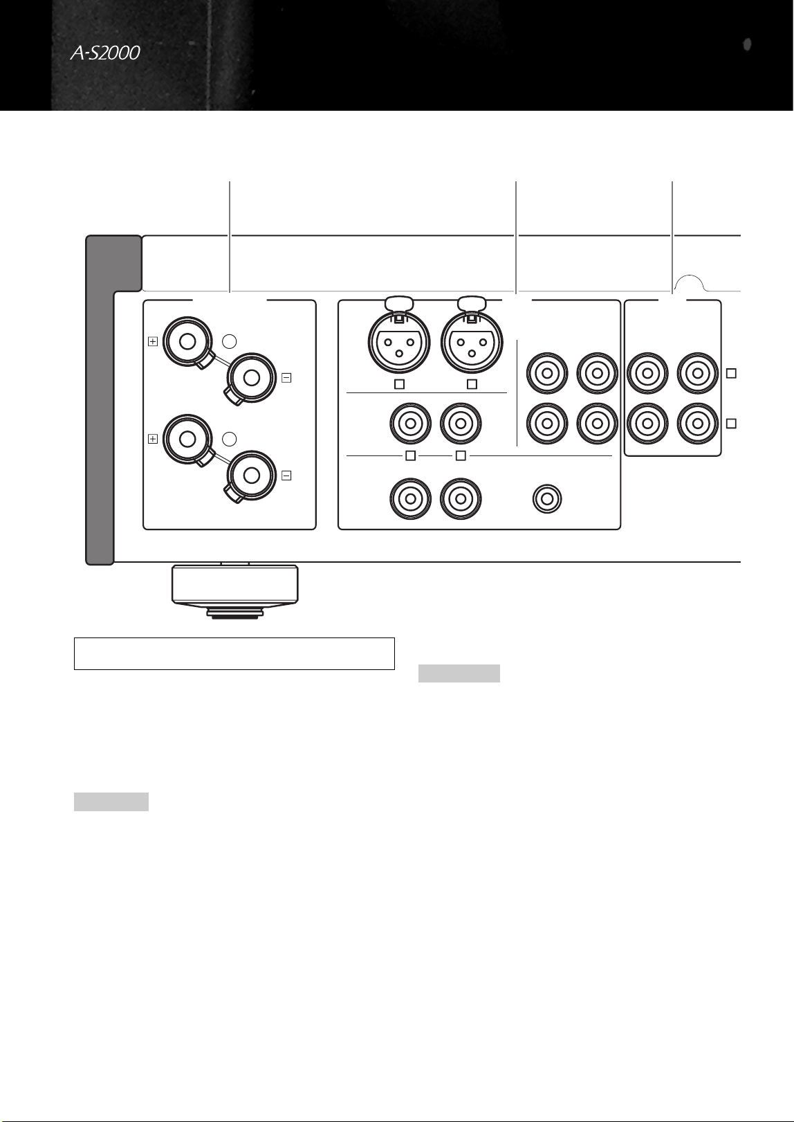
1 SPEAKERS L/R CH terminals
2 INPUT jacks
3 LINE2 jacks
4 MAIN IN jacks
Adjust the volume level using the volume control on the external
amplifier connected to the MAIN DIRECT jacks when you select
MAIN DIRECT as the input source.
5 PRE OUT jacks
• When you connect audio pin plugs to the PRE OUT jacks to
drive the speakers using an external amplifier, it is not
necessary to use the SPEAKERS L/R CH terminals.
• The signal output at the PRE OUT jacks are affected by the tone
control settings.
• The PRE OUT jacks output the same channel signal as the
SPEAKERS L/R CH terminals.
• When you use a subwoofer, connect it to the PRE OUT jacks
and speakers to the SPEAKERS L/R CH terminals.
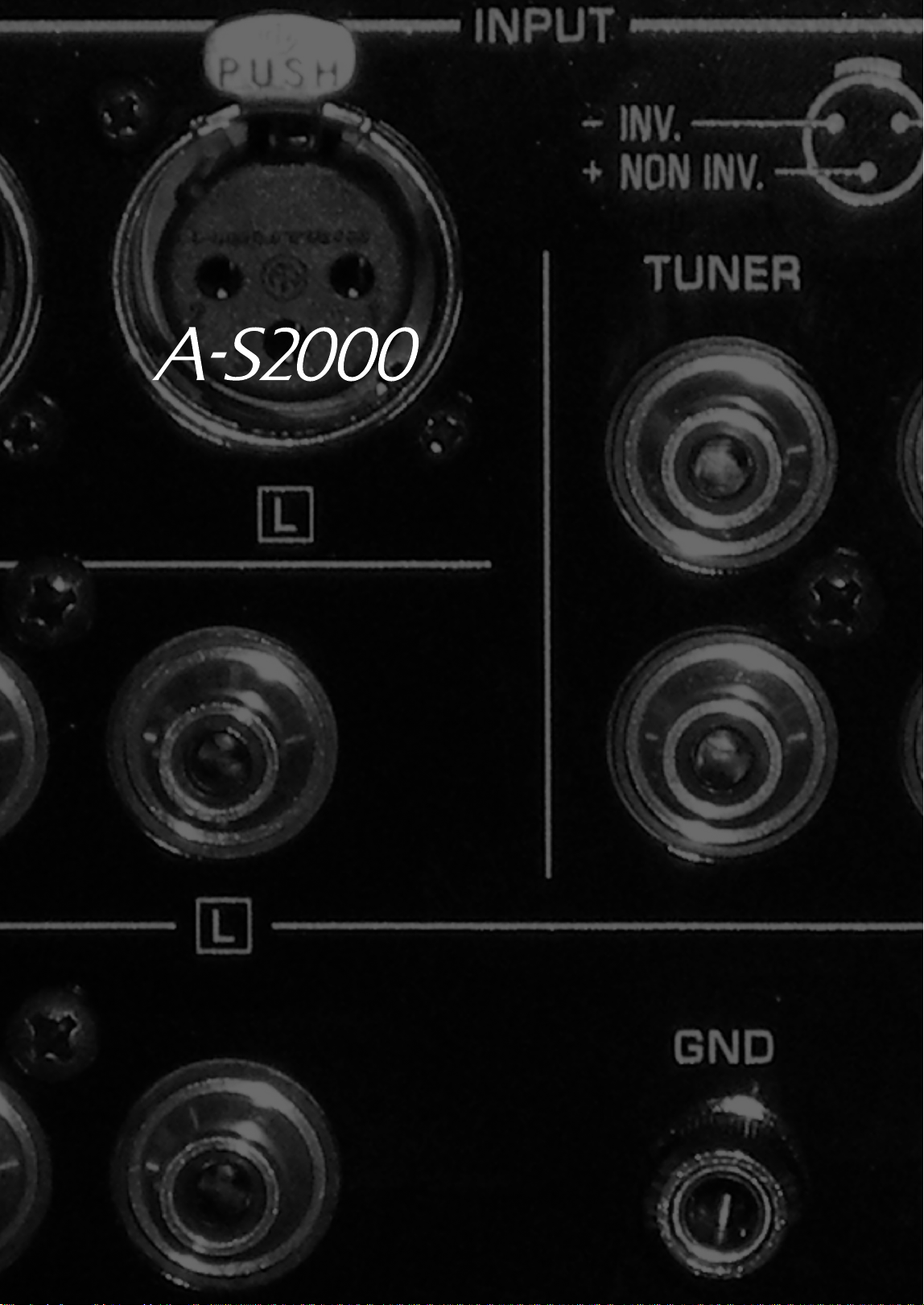
LINE2
RECPBLINE 1TUNER
GND
L
R
LR
PHONO
CD
CD
BAL
INPUTSPEAKERS R CH
A
B
L
R
1 23
See page 14 for connection information.
Note
Notes
11 En
6 AC IN
Use this inlet to plug in the supplied power cable.
7 VOLTAGE SELECTOR
(Asia and General models only)
The VOLTAGE SELECTOR on the rear panel of this unit
must be set for your local main voltage BEFORE plugging
the AC power cable into the AC wall outlet. Improper
setting of the VOLTAGE SELECTOR may cause damage
to this unit and create a potential fire hazard.
Rotate the VOLTAGE SELECTOR clockwise or
counterclockwise to the correct position using a straight
slot screwdriver.
Voltages are as follows:
AC 110/120/220/230–240 V, 50/60 Hz
8 Foot
The feet of this unit include built-in spikes. Using the
spikes can reduce the effect of vibrations on the set. When
using the spikes, remove the magnet foot by pulling it.
When using the feet’s built-in spikes, the spikes may scratch the
shelf or floor on which this unit is installed. Use the supports
when placing this unit on expensive furniture, etc.
y
If this unit is unstable, you can adjust the foot height by rotating
it.
AC IN
SPEAKERS L CH
PRE OUTMAIN IN
L
R
A
B
VOLTAGE SELECTOR
5 1 7
8
64
230-
240V
Caution
Spike
English
12 En
Controls and functions
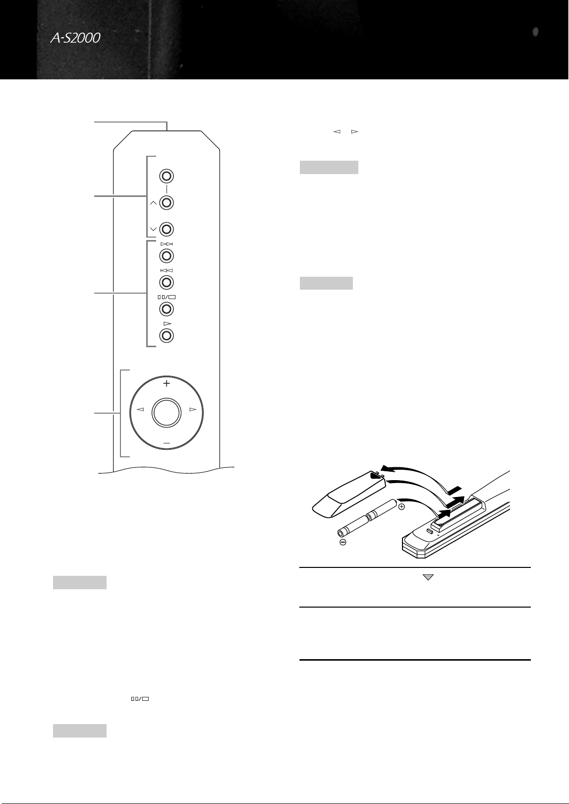
■ Remote control
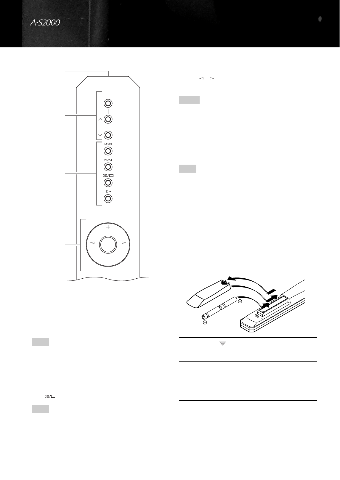
1 Infrared signal transmitter
Outputs infrared control signals.
2 Yamaha tuner control buttons
Control functions of Yamaha tuner. Refer to the owner’s
manual of your tuner for details.
Some components may not be controlled by this remote control.
3 Yamaha CD player control buttons
Control various functions of Yamaha CD player. Refer to
the owner’s manual of your CD player for details.
y
Press once to pause and twice to stop playback.
Some components may not be controlled by this remote control.
4 Amplifier control buttons
INPUT /
Selects the input source you want to listen to.
• When MAIN DIRECT is selected as the input source, no
signals are output at the PRE OUT and REC jacks.
• If headphones are plugged into the PHONES jack while MAIN
DIRECT is selected as the input source, no audio is output at
the PHONES jack.
VOL +/–
Controls the volume level.
The VOLUME control does not affect when you select MAIN
DIRECT as the input source. Adjust the volume level using the
volume control on the external amplifier connected to the MAIN
DIRECT jacks.
MUTE
Reduces the current volume level by approximately 20
dB. Press again to restore the audio output to the previous
volume level.
y
You can also press VOL +/– to resume the audio output.
■ Installing batteries in the remote control
1 Press the part and slide the battery
compartment cover off.
2 Insert the two supplied batteries
(AA, R6, UM-3) according to the polarity
markings (+ and –) on the inside of the
battery compartment.
3 Slide the cover back until it snaps into place.
Note
Note
A/B/C/D/E
PRESET
INPUTINPUT
VOL
MUTE
VOL
1
2
3
4
Notes
Note
2
1
3
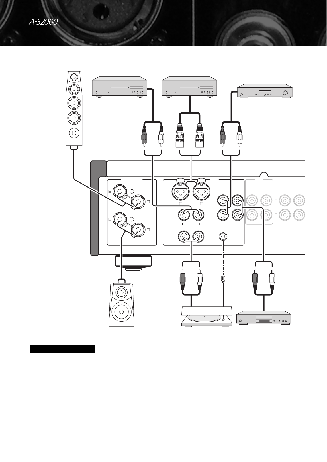
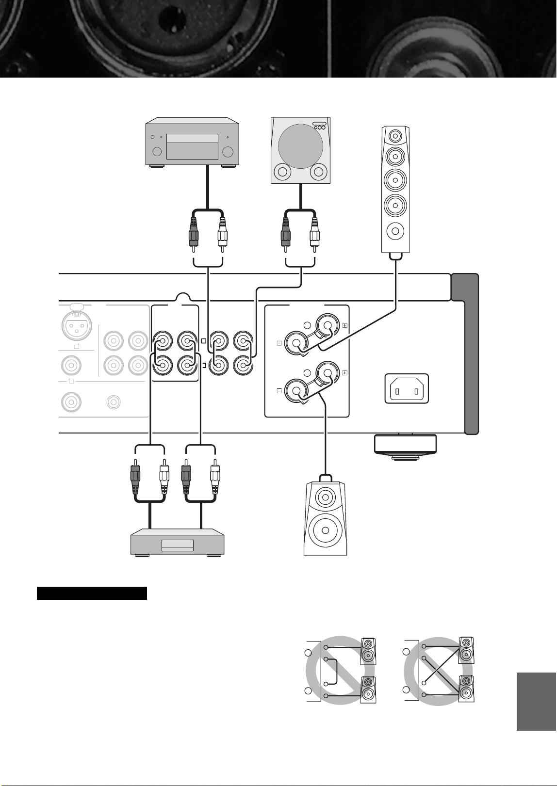
Connections
In this section, you will make connections between A-S2000, speakers,
and source components.
14 En
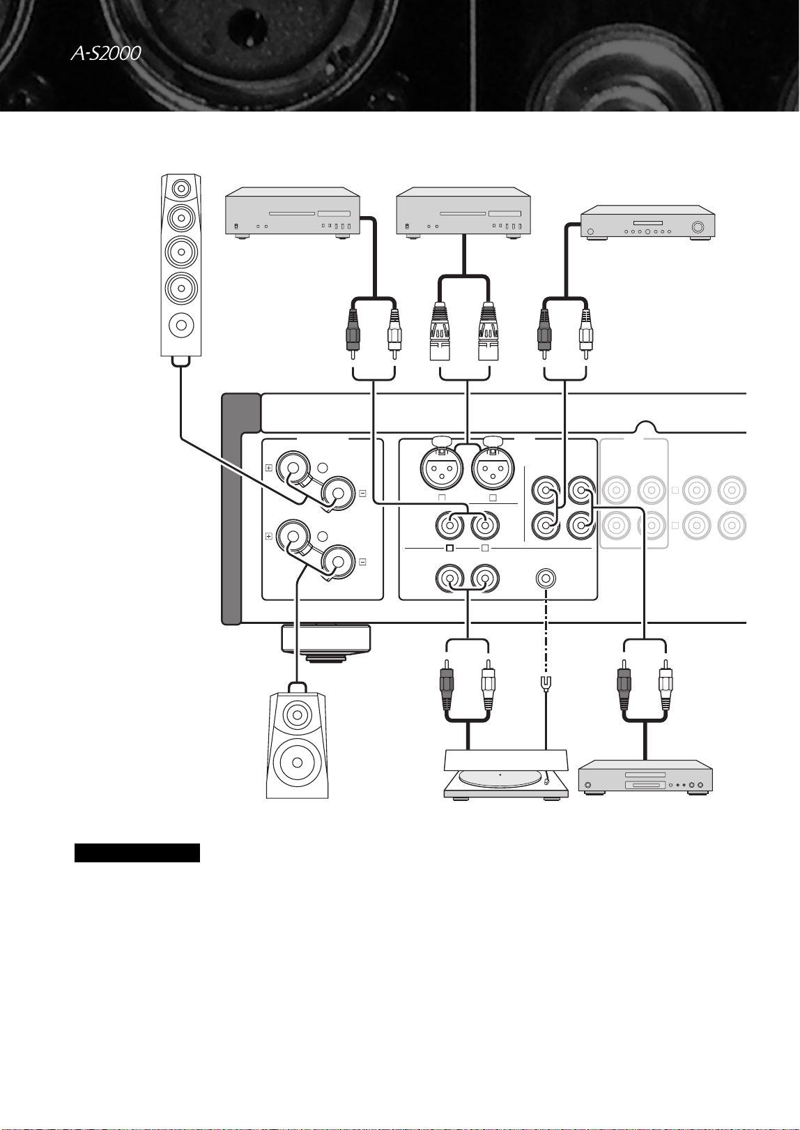
Connections
• Do not let the bare speaker wires touch each other or do not let
them touch any metal part of this unit. This could damage this
unit and/or the speakers.
• All connections must be correct: L (left) to L, R (right) to R,
“+” to “+”, and “–” to “–”. If the connections are faulty, no
sound will be heard from the speakers, and if the polarity of the
speaker connections is incorrect, the sound will be unnatural
and lack bass. Also, refer to the owner’s manual for each of
your components.
• Use RCA unbalanced cables to connect other components
except speakers. Use “male” XLR balanced cables to connect a
CD player with XLR balanced output jacks to the CD BAL
jacks of this unit.
• Connect your turntable to the GND terminal to reduce noise in
the signal. However, you may hear less noise without the
connection to the GND terminal for some record players.
Caution
LINE2
PRE OUTMAIN IN
RECPBLINE 1TUNER
GND
L
R
LR
PHONO
CD
CD
BAL
INPUTSPEAKERS R CH
A
B
L
R
+
-
+
-
CD player with
RCA jacks
Ground
Speakers A
(R channel)
Speakers B
(R channel)
CD player with
XLR jacks
Tuner
Turntable
DVD player,
etc.
15 En
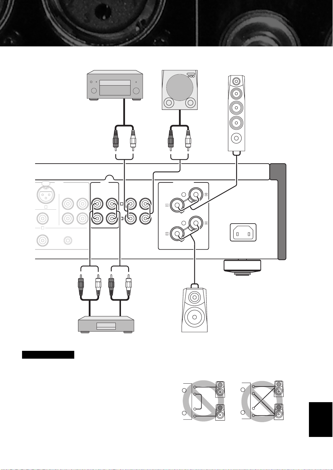
• Because the power amplifier of A-S2000 is of the floating
balanced type, the following types of connections are not
possible.
– Connecting with the left channel “–” terminal and the right
channel “–” terminal as well as “+” terminals (Fig. 1).
– Deliberately connecting with the left/right channel “–”
terminals and metal part on the rear panel of this unit, as well
as accidentally touching them.
– Connecting with the left channel “–” terminal and the right
channel “–” terminal inverted (cross connection, Fig. 2).
• Do not connect your active subwoofer to the SPEAKERS
terminal. Connect it to the PRE OUT jacks of this unit.
Caution
AC IN
SPEAKERS L CH
LINE2
PRE OUTMAIN IN
RECPBLINE 1TUNER
GND
L
L
INPUT
L
R
A
B
+–
+
-
CD recorder,
tape deck, etc.
Speakers A
(L channel)
Speakers B
(L channel)
External amplifier or
active subwoofer
Preamplifier,
AV receiver, etc.
+
–
+
–
L
R
+
–
+
–
L
R
+
–
+
–
L
R
+
–
+
–
L
R
Fig. 1 Fig. 2
English
16 En
Connections
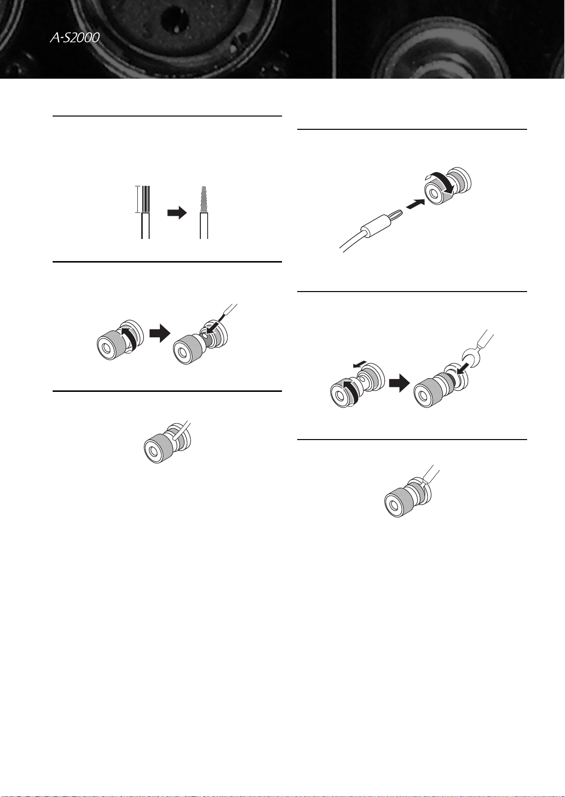
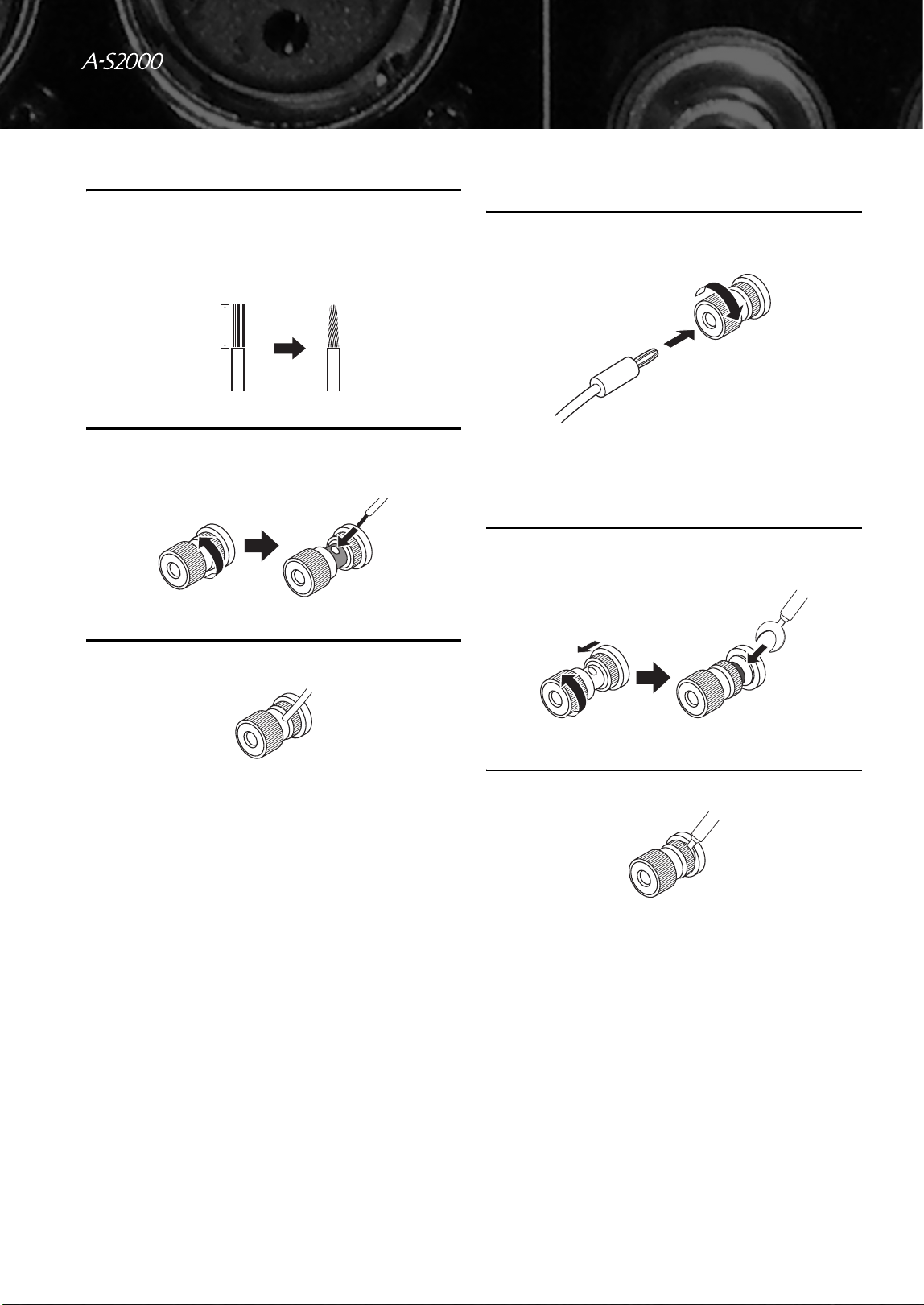
■ Connecting the speakers
1 Remove approximately 10 mm (0.4 in) of
insulation from the end of each speaker
cable and twist the exposed wires of the
cable together to prevent short circuits.
2 Unscrew the knob and then insert the bare
wire into the hole.
3 Tighten the knob.
■ Connecting the banana plug
(Except for Europe models)
First, tighten the knob and then insert the banana
plug into the end of the corresponding terminal.
■ Connecting the Y-shaped lug
1 Unscrew the knob and then sandwich the Y-
shaped lug between the ring part and base.
2 Tighten the knob.
10 mm (0.4 in)
Banana plug
Y-shaped lug
Slide
17 En
■ Bi-wire connection
The bi-wire connection separates the woofer from the
combined midrange and tweeter section. A bi-wire
compatible speaker has four binding post terminals. These
two sets of terminals allow the speaker to be split into two
independent sections. This split connects the mid and high
frequency drivers to one set of terminals and the low
frequency driver to the other pair.
To use the bi-wire connections, the impedance of each speaker
must be 8 Ω or higher.
• Remove the shorting bars or bridges to separate the LPF (low
pass filter) and HPF (high pass filter) crossovers.
• To use the bi-wire connections, switch the SPEAKERS selector
to the A+B BI-WIRING position.
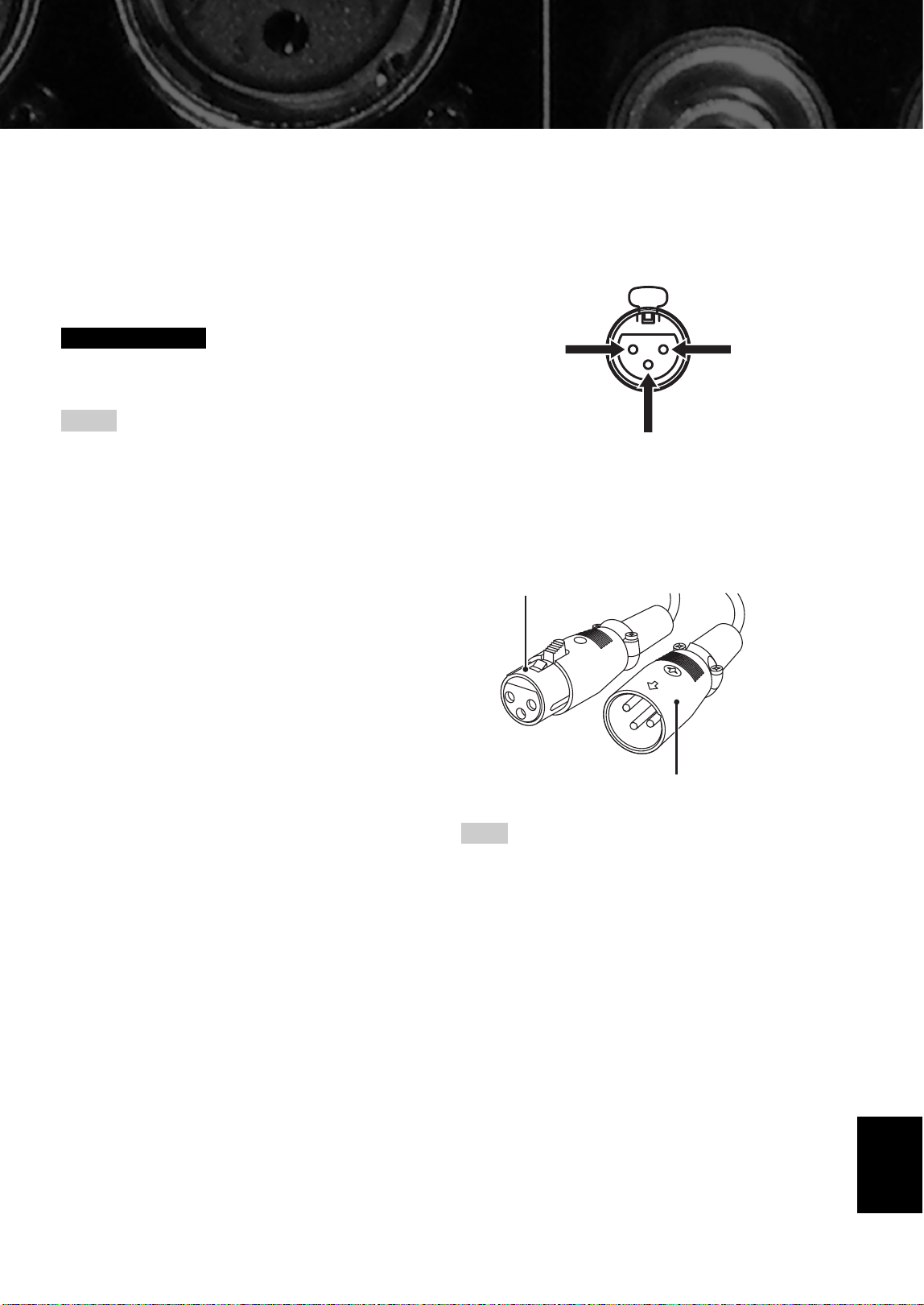
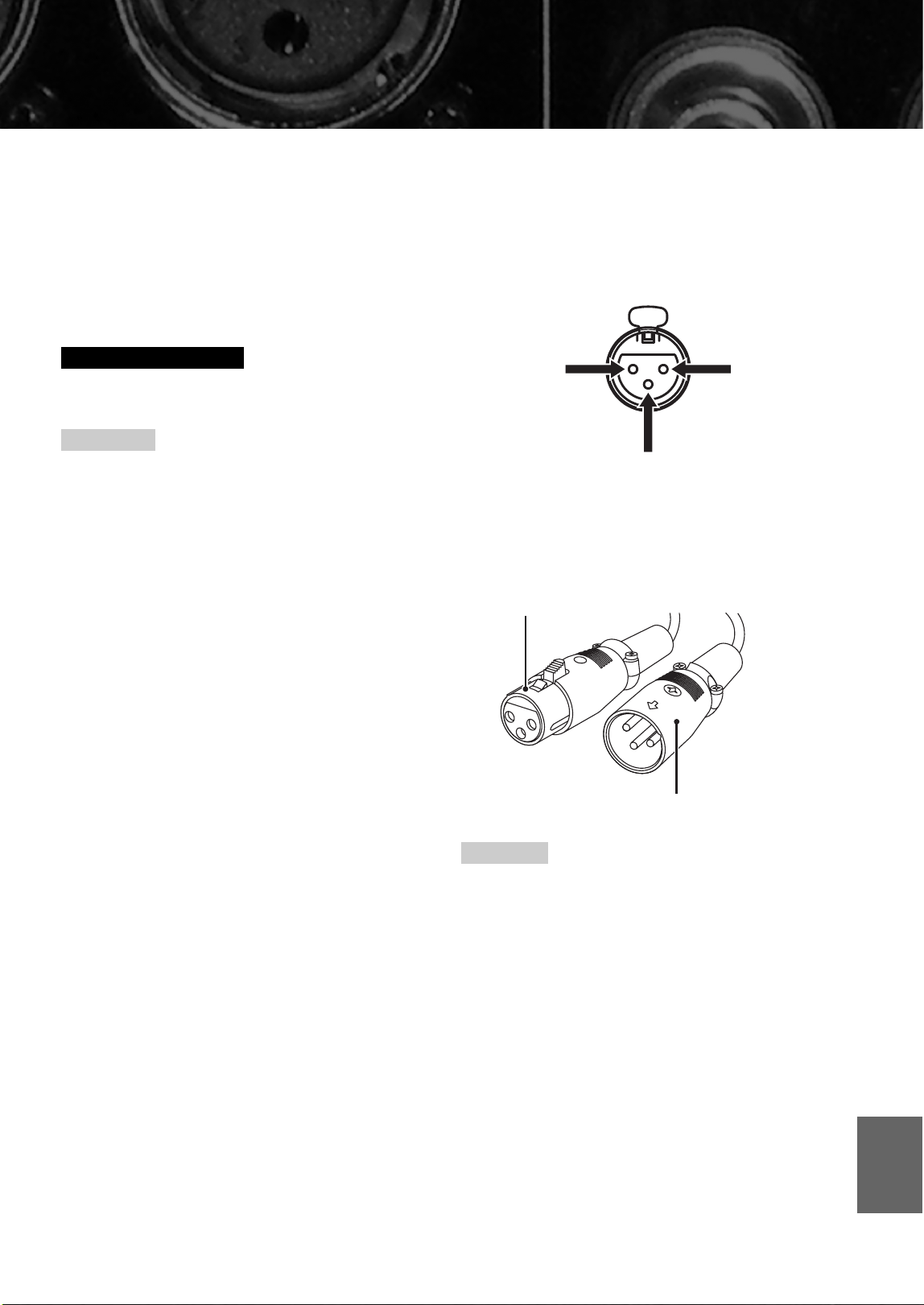
■ Connecting to the CD BAL jacks
Connect your CD player with the XLR balanced output
jacks. The pin assignments for these jacks are shown
below. Refer to the owner’s manual supplied with your
CD player and verify that its XLR balanced output jacks
are compatible with the pin assignments.
When connecting, be sure to match the pins and insert the
connector of the “male” XLR balanced cable until you
hear a “click”. When disconnecting, pull out the “male”
XLR balanced cable while holding down the lever of the
CD BAL jacks.
To use the XLR balanced connection, you must switch the
INPUT selector on the front panel to the CD BAL position.
Caution
Notes
Note
1: ground2: hot
3: cold
“Female” XLR connector
“Male” XLR connector
English
18 En
Connections
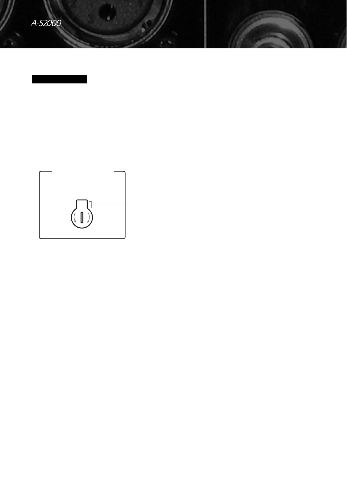
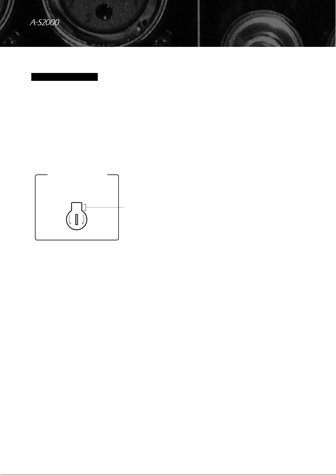
■ VOLTAGE SELECTOR
(Asia and General models only)
The VOLTAGE SELECTOR on the rear panel of this unit
must be set for your local voltage BEFORE plugging the
power cable into the AC wall outlet. Improper setting of
the VOLTAGE SELECTOR may cause damage to this
unit and create a potential fire hazard.
Rotate the VOLTAGE SELECTOR clockwise or
counterclockwise to the correct position using a straight
slot screwdriver.
Voltages are as follows:
........................AC 110/120/220/230–240 V, 50/60 Hz
■ Connecting the power cable
Plug the power cable into the AC IN connector when all
connections are complete, and then plug in the power
cable to the AC outlet.
Caution
230-
240V
VOLTAGE SELECTOR
Voltage
indication
Specifications
In this section, you will find technical specifications for A-S2000.

20 En
Specifications
POWER SECTION
• Minimum RMS Output Power
(8 Ω , 20 Hz to 20 kHz, 0.02% THD) ...................... 90 W + 90 W
(4 Ω , 20 Hz to 20 kHz, 0.02% THD) .................. 150 W + 150 W
• Dynamic Power (IHF) (8/6/4/2 Ω) ................... 105/135/190/220 W
• Maximum Output Power
(1 kHz, 0.7% THD, 4 Ω) [U.K. and Europe models only]
.......................................................................................... 160 W
• Maximum Useful Output Power (JEITA)
(1 kHz, 10% THD, 8/4 Ω)
[Asia, General, China and Korea models only] ....... 120/190 W
• Dynamic Headroom
8 Ω ..................................................................................... 0.67 dB
• IEC Output Power [U.K. and Europe models only]
(1 kHz, 0.02% THD, 8/4 Ω)............................................ 95/155 W
• Damping Factor
1 kHz, 8 Ω ................................................................................ 160
• Maximum Input Signal
CD BAL, CD, etc. ................................................................. 2.8 V
PHONO MM (1 kHz) ........................................................ 120 mV
PHONO MC (1 kHz) ............................................................ 7 mV
• Frequency Response
CD, etc. (Flat Position, 5 Hz to 100 kHz) ...................... +0/−3 dB
CD, etc. (Flat Position, 20 Hz to 20 kHz) ................... +0/−0.3 dB
• RIAA Equalization Deviation
PHONO MM (20 Hz to 20 kHz) ...................................... ±0.5 dB
PHONO MC (20 Hz to 20 kHz) ....................................... ±0.5 dB
• Total Harmonic Distortion
CD BAL to SP OUT
(20 Hz to 20 kHz, 90 W/8 Ω) ............................................. 0.01%
CD, etc. to SP OUT
(20 Hz to 20 kHz, 90 W/8 Ω) ........................................... 0.015%
PHONO MM to REC
(20 Hz to 20 kHz, 2 V) ..................................................... 0.005%
PHONO MC to REC
(20 Hz to 20 kHz, 2 V) ....................................................... 0.05%
• Intermodulation Distortion
CD, etc. to SP OUT
(Rated output/8 Ω) ............................................................. 0.02%
• Signal to Noise Ratio (IHF-A Network)
CD, etc. (150 mV, Input shorted) ..........................................98 dB
PHONO MM (5 mV, Input shorted) .....................................93 dB
PHONO MC (500 µV, Input shorted) ..................................85 dB
• Residual Noise (IHF-A Network) (CD, etc.) .......................... 33 µV
CONTROL SECTION
• Input Sensitivity/Input Impedance
CD, etc. .................................................................. 150 mV/47 kΩ
MM ......................................................................... 2.5 mV/47 kΩ
MC ........................................................................... 100 µV/50 Ω
MAIN IN ...................................................................... 1 V/47 kΩ
• Output Level/Output Impedance
REC OUT ............................................................. 150 mV/1.5 kΩ
PRE OUT ..................................................................... 1 V/1.5 kΩ
• Headphone Rated Output
1 kHz, 32 Ω , 0.2% THD ................................................... 30 mW
• Channel Separation
CD, etc. (5.1 kΩ Terminated, 1 kHz/10 kHz) ................. 74/54 dB
PHONO MM (Input shorted, 1 kHz/10 kHz, Vol.:−30 dB)
....................................................................................... 90/77 dB
PHONO MC (Input shorted, 1 kHz/10 kHz, Vol.:−30 dB)
....................................................................................... 66/77 dB
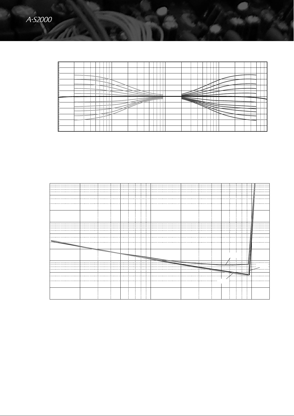
• Tone Control Characteristics
BASS
Boost/Cut (50 Hz) ............................................................. ±9 dB
Turnover Frequency ........................................................ 350 Hz
TREBLE
Boost/Cut (20 kHz) ........................................................... ±9 dB
Turnover Frequency ....................................................... 3.5 kHz
• Audio muting......................................................... –20 dB (approx.)
GENERAL
• Power Supply
[U.S.A. and Canada models] ............................. AC 120 V, 60 Hz
[Asia model] .................................. AC 220/230–240 V, 50/60 Hz
[General model] ............... AC 110/120/220/230–240 V, 50/60 Hz
[China model] .................................................... AC 220 V, 50 Hz
[Korea model] .................................................... AC 220 V, 60 Hz
[Australia model] ............................................... AC 240 V, 50 Hz
[U.K. and Europe models] ................................. AC 230 V, 50 Hz
• Power consumption ................................................................ 350 W
• Idling power consumption ......................................................... 80 W
• Off-state power consumption ...................................................... 0 W
• Dimensions (W x H x D) ................................. 435 x 137 x 465 mm
(17-1/8” x 5-3/8” x 18-5/16”)
• Weight .................................................................... 22.7 kg (50 lbs.)
* Specifications are subject to change without notice.
01EN_03_Add_A-S2000_UCAB.fm Page 20 Wednesday, August 6, 2008 1:08 PM
Black process 45.0° 240.0 LPI
21 En
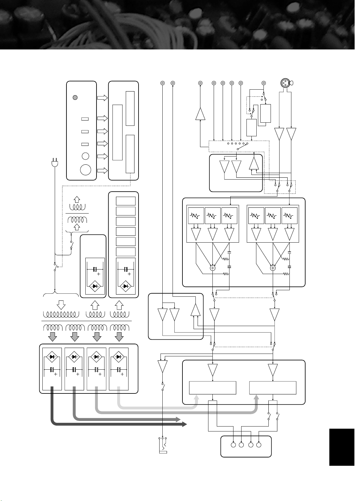
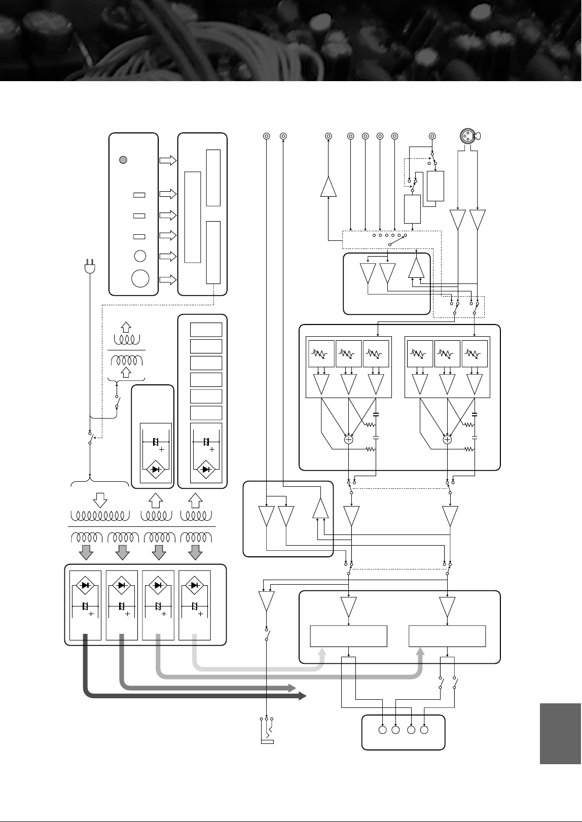
■ Block diagram
CD BAL
PHONO
CD
SPEAKERS L CH
PHONES
TUNER
LINE1
LINE2 PB
LINE2 REC
PRE OUT
MAIN IN
BUFFER AMP
µ COM
for µ COM
PROTECTION
REMOTE
BASS
TREBLE
BALANCE
FRONT PANEL
INPUT SEL
VOLUME
CONTROL
SUB TRANSFORMER
MAIN TRANSFORMER
INDEPENDENT CURRENT REGULATED POWER SUPPLY (for AUDIO)
INDEPENDENT FLOATING
POWER SUPPLY
(for POWER AMP / VOLTAGE AMP STAGE)
POWER SWITCH
for MC AMP
for EQ AMP
for LINE AMP1
for LINE AMP2
for VOLUME1
for VOLUME2
BUFFER AMP
INPUT SELECTOR
VOLUME & TONE CONTROL
FLOATING BALANCE
POWER AMPLIFIER
to POWER AMP
R CH
LOW IMPEDANCE DRIVE
HEADPHONE AMP
A
B
+
–
+
–
SPEAKER DRIVER
HOT (POSITIVE PHASE) SIDE
SPEAKER DRIVER
COLD (NEGATIVE PHASE) SIDE
HOT
HOT
HOT
TONE CONTROL DEVICES
SP A L CH
SP B L CH
FLAT
MAIN DIRECT
TONE CONTROL/FLAT
ATT. 1
ATT. 2
ATT. 3
TONE CONTROL DEVICES
FLAT
ATT. 4
ATT. 5
ATT. 6
COLD
COLD
COLD
L CH
for HOT
L CH
for COLD
R CH
for HOT
R CH
for COLD
EQ AMP
HOT (POSITIVE PHASE)
COLD (NEGATIVE PHASE)
MC
HEAD AMP
MM/MC
UNBALANCE
⇐⇒
BALANCE
CONVERTER
BALANCE
⇐⇒
UNBALANCE
CONVERTER
English
22 En
Specifications
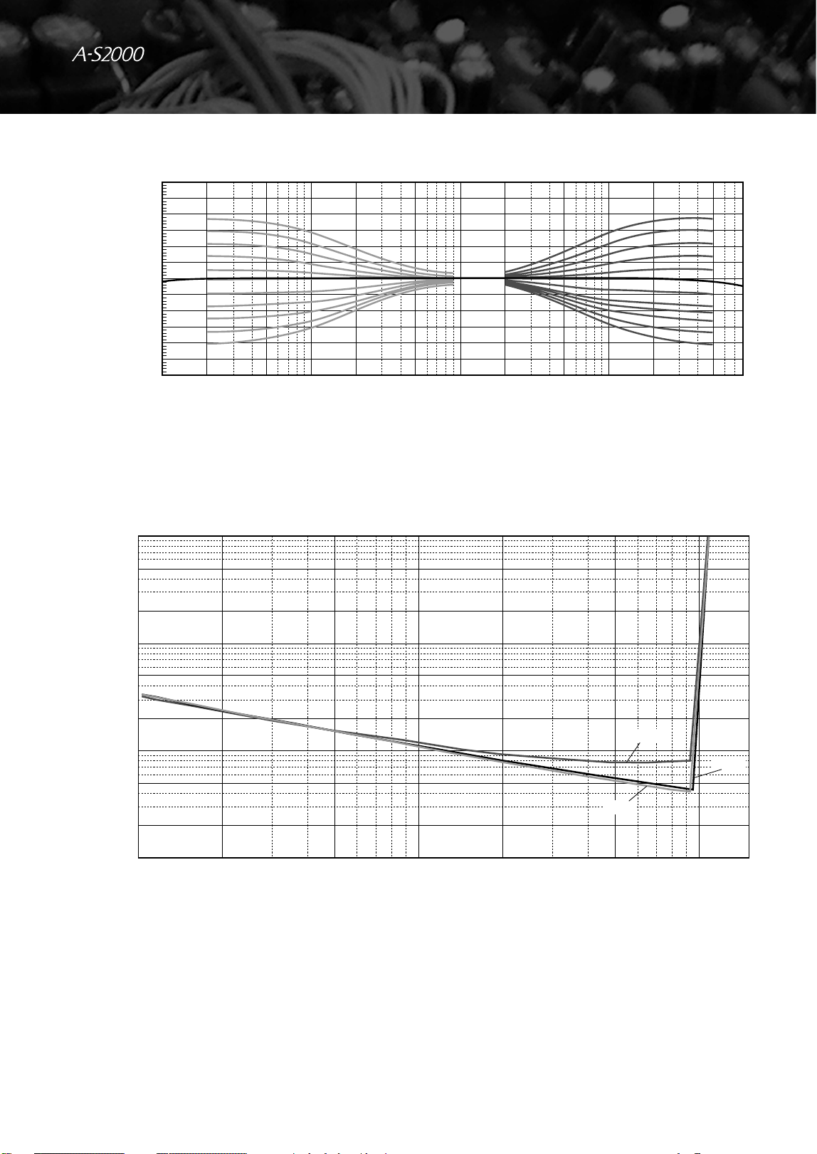
■ Tone control characteristics
■ Total harmonic distortion
+15
+12.5
+10
+7.5
+5
+2.5
0
–2.5
–5
–7.5
–10
–12.5
–15
10 20 50 100 200 500 1k
Frequency (Hz)
Response (dB)
2k 5k 10k 20k 50k 100k
1
0.5
0.05
0.005
0.2
0.02
0.002
0.1
0.01
0.001
2510
Output (W)
THD + N Ratio (%)
20 50 100
20Hz
1kHz
20kHz
23 En
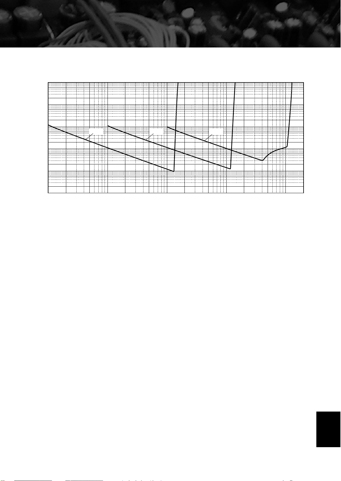
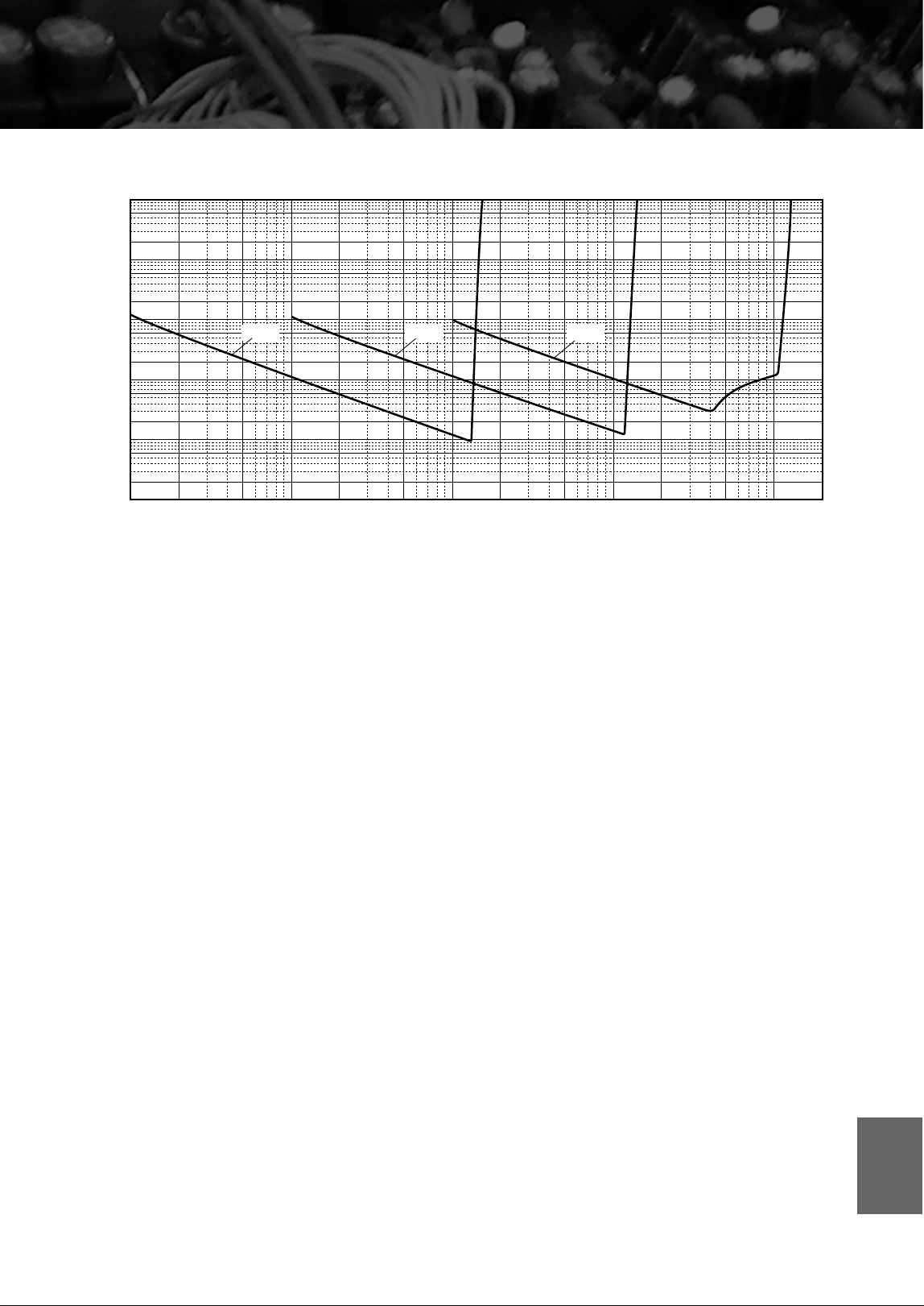
■ Total harmonic distortion (PHONO)
10
5
2
1
0.5
0.2
0.02
0.002
0.0002
0.1
0.01
0.001
0.0001
0.05
0.005
0.0005
100µ 200µ 500µ 1m 2m 5m 10m 20m
20Hz 1kHz 20kHz
Input (Vrms)
50m 100m 200m 500m 1 2
THD + N Ratio (%)
English
24 En
Troubleshooting
Refer to the chart below if this unit does not function properly. If the problem you are experiencing is not listed below or
if the instructions below do not help, turn off this unit, disconnect the AC power cable, and contact the nearest authorized
Yamaha dealer or service center.
Problem Cause Remedy
See
page
This unit fails to turn
on.
The AC power cable is not connected to
the AC IN inlet on the rear panel or not
plugged in the AC wall outlet.
Connect the AC power cable firmly.
18
The protection circuitry has been activated
because of a short circuit, etc.
Check that the speaker wires are not touching each
other or shorting out against the rear panel of this
unit, and then turn the power of this unit back on.
14
This unit has been exposed to a strong
external electric shock (such as lightning
or strong static electricity).
Turn off this unit, disconnect the AC power cable,
plug it back in after 30 seconds, and then use it
normally.
—
The POWER indicator
on the front panel
flashes.
The protection circuitry has been activated
because of a short circuit, etc.
Check that the speaker wires are not touching each
other or shorting out against the rear panel of this
unit, and then turn the power of this unit back on.
14
There is a problem with the internal
circuitries of this unit.
Disconnect the AC power cable and contact the
nearest authorized Yamaha dealer or service center.
—
The INPUT indicator
on the front panel
flashes and the
volume is turned
down when you turn
on this unit.
The protection circuitry has been activated
because of a short circuit, etc.
Check that the speaker wires are not touching each
other or shorting out against the rear panel of this
unit, and then turn the power of this unit back on.
14
No sound. Incorrect input or output cable
connections.
Connect the cables properly. If the problem persists,
the cables may be defective.
14
No appropriate input source has been
selected.
Select an appropriate input source with the INPUT
selector on the front panel (or one of the input
selector buttons on the remote control).
—
The SPEAKERS switch is not set
properly.
Switch the SPEAKERS switch to the appropriate
position.
—
Speaker connections are not secure. Secure the connections.
14
The sound suddenly
goes off.
The protection circuitry has been activated
because of a short circuit, etc.
Check that the speaker wires are not touching each
other or shorting out against the rear panel of this
unit, and then turn the power of this unit back on.
14
Only the speaker on
one side can be
heard.
Incorrect cable connections. Connect the cables properly. If the problem persists,
the cables may be defective.
14
Incorrect setting for the BALANCE
control.
Set the BALANCE control to the appropriate
position.
—
There is a lack of bass
and no ambience.
The + and – wires are connected in
reverse at the amplifier or the speakers.
Connect the speaker wires to the correct + and –
phase.
14
A “humming” sound
is heard.
Incorrect cable connections. Connect the audio cable plugs firmly. If the problem
persists, the cables may be defective.
14
No connection from the turntable to the
GND terminal.
Connect the turntable to the GND terminal of this
unit.
14
25 En
Problem Cause Remedy
See
page
The volume level is
low while playing a
record.
Incorrect setting for the PHONO switch
on the front panel.
Switch the PHONO switch to the MM or MC position
according to the type of magnetic cartridge of the
turntable.
—
The sound is
degraded when
listening with the
headphones
connected to the CD
player connected to
this unit.
The power of this unit is turned off. Turn on the power of this unit.
—
The remote control
does not work or
function properly.
Wrong distance or angle. The remote control functions within a maximum
range of 6 m (20 ft) and no more than 30 degrees off-
axis from the front panel.
6
Direct sunlight or lighting (from an
inverter type of fluorescent lamp, etc.) is
striking the remote control sensor of this
unit.
Reposition this unit.
—
The batteries are weak. Replace all batteries.
12
Taking care of this unit
When you wipe this unit, do not use chemical solvents
(ex. alcohol or thinner etc.); this might damage the
finish. Use a clean, dry cloth. For heavy dirt, dampen a
soft cloth in detergent diluted with the water, wring it
out, and then clean this unit up with the cloth.
The screws on the side panels may loosen as wood
expands and contracts. In this case, tighten the screws.
English

La Hi-Fi doit ses débuts à
Yamaha
La passion de Yamaha pour la musique remonte à plus d’un siècle, plus
exactement à 1887, l’année où nous avons conçu notre première orgue à
anche. Actuellement, nous sommes le principal producteur de pianos et
d’instruments de musique au monde, et nous sommes impliqués de
multiples façons dans le domaine musical. Nous fabriquons des
équipements d’enregistrement professionnels, nous concevons des salles
de concert et assistons les artistes à effectuer réglages et accordage sonores
pour les concerts.
Notre production de composants audio profite de maintes manières
de ce savoir et de cette expérience. Nous avons commercialisé notre
premier tourne-disque Hi-Fi (Haute Fidélité) en 1954. Nous avons été
ensuite une des premières sociétés à produire en masse des appareils audio
de haute qualité et à introduire d’innombrables composants stéréo
légendaires.
Nous espérons que vous apprécierez l’expérience Hi-Fi unique du
Yamaha Natural Sound.
L’excellence dans l’accomplissement audio
Premier Système Hi-Fi introduit en 1920
Nous avons introduit de nombreux
composants Hi-Fi (tourne-disques, tuners
FM/AM, amplificateurs intégrés, préamplis,
amplificateurs de puissance et enceintes) en
1955 – 1965.
Commercialisation de la série d’enceintes
Natural Sound en 1967
Enceinte de contrôle NS-20
Amplificateur intégré CA-1000
Faisant partie des appareils de Classe A, le CA-1000
devient un standard en matière d’amplificateurs intégrés.
Enceinte de contrôle NS-690
Enceinte de contrôle NS-1000M
Une enceinte véritablement légendaire, toujours vénérée
par les passionnés de Hi-Fi.
Amplificateur de puissance B-1
Un ampli innovant utilisant des transistors FET à tous les
étages.
Amplificateur de commande C-2
A reçu le premier prix au Salon International de la Musique
et de la Hi-Fi de Milan.
Enceinte de contrôle pour studio NS-10M
Devenue une des enceintes de studio les plus populaires au
monde.
Amplificateur intégré A-1
Tourne-disque PX-2
Le premier tourne-disque à bras droit de Yamaha.
Amplificateur de puissance B-6
Amplificateur de puissance pyramidal.
Tourne-disque GT-2000/L
Premier lecteur de CD
(
CD-1
)
commercialisé en1983
Amplificateur de puissance B-2x
Amplificateur de puissance MX-10000 et
Amplificateur de commande CX-10000
Ont redéfini les fonctionnalités des composants séparés.
Amplificateur intégré AX-1
Systèmes d’enceintes Natural Sound
Soavo-1
et
Soavo-2
Amplificateur stéréo A-S2000 et
Lecteur de Super Audio CD CD-S2000
Lecteur de CD GT-CD1
Amplificateur de puissance MX-1 et
Préamplificateur CX-1
4 Fr
◆
La conception des circuits entièrement à symétrie flottante permet d’atteindre
pour la première fois tout le potentiel de l’amplification analogique
Un tout nouvel amplificateur de puissance à symétrie flottante qui atteint une parfaite symétrie et permet une
transmission totalement symétrique (amplification) depuis la prise d’entrée jusque devant la prise d’enceinte
◆ Transmission du signal symétrique à tous les étages
Le premier amplificateur intégré au monde à offrir une transmission symétrique sur tous les étages, combinant à la fois
une grande puissance de sortie avec une bonne texture sonore et une performance R/N exceptionnelle
◆ Amplificateur de puissance à symétrie flottante
◆ Amplificateur de commande entièrement symétrique
◆
Commandes de volume et de tonalité numériques entièrement symétriques
◆ Quatre sources d’alimentation de grande capacité
◆ Construction symétrique
◆ Amplificateur de casque pour circuit d’attaque à basse impédance
■ Accessoires fournis
Veuillez vous assurer que tous les articles suivants vous ont bien été fournis.
• Boîtier de télécommande
• Piles (AA, R6, UM-3) (×2)
• Cordon d’alimentation
• Brochure sur la sécurité
■ À propos de ce manuel
• Le symbole y appelle votre attention sur un conseil d’utilisation.
• Ce mode d’emploi a été imprimé avant la fabrication de l’appareil. Les caractéristiques et la présentation ont pu être modifiées à fin
d’amélioration, etc. En cas de divergence entre le mode d’emploi et l’appareil, ce dernier prime.
• La couleur des images dans ce manuel peut être différente de l’original.
• Avant d’utiliser cet appareil, veuillez lire la brochure sur la sécurité.
Table des matières
Commandes et fonctions....................................................................................................................................... 6
Raccordements .................................................................................................................................................... 14
Caractéristiques techniques ............................................................................................................................... 20
Guide de dépannage............................................................................................................................................ 24
5 Fr
Commandes et fonctions
Ce chapitre décrit les commandes et fonctions du A-S2000.
6 Fr
Commandes et fonctions
■ Face avant (côté gauche)
1 POWER
Appuyez vers le haut ou le bas pour mettre cet appareil
sous ou hors tension.
y
Le témoin POWER au-dessus de la touche s’allume lorsque cet
appareil est sous tension.
• Si le témoin POWER clignote lorsque vous mettez cet appareil
sous tension, débranchez le câble d’alimentation secteur et
contactez le revendeur ou service après-vente agréé Yamaha le
plus proche (voir page 24).
• Lorsque vous mettez l’appareil sous tension, il faut attendre
quelques secondes pour que l’appareil puisse reproduire le son.
2 Capteur de télécommande
Il reçoit les signaux émis par le boîtier de télécommande.
Le boîtier de télécommande émet un faisceau infrarouge
étroit. Veillez à le pointer directement sur le capteur de
télécommande de l’appareil pour en assurer le
fonctionnement.
SPEAKERSTRIMPHONESPOWER
OFF
ON
dB
A
B
A+B
BI-WIRING
0
-6
+6
+12
OFF
BASS
+
-
41325
Remarques
30 30
Environ 6 m
7 Fr
3 Prise PHONES
Fournit les signaux audio destinés à l’écoute au casque.
Lorsqu’un casque est branché:
– Les deux paires d’enceintes raccordées aux bornes
SPEAKERS L/R CH A et B sont désactivées.
– Aucun signal n’est transmis aux prises PRE OUT, lorsque des
signaux sont transmis aux prises REC.
– Vous ne pouvez pas sélectionner MAIN DIRECT comme
source d’entrée.
– Si le casque est branché sur la prise PHONES lorsque
MAIN DIRECT est sélectionné comme source d’entrée, aucun
son n’est transmis à la prise PHONES.
4 TRIM
Ajuste le niveau sonore lorsque le casque est branché pour
éviter les changements subits de volume.
Choix: –6 dB, 0 dB, +6 dB, +12 dB
5 SPEAKERS
Met en et hors service la paire d’enceintes raccordées aux
bornes SPEAKERS L/R CH A et/ou B situées sur le
panneau arrière.
• Réglez sur OFF pour mettre la paire d’enceintes hors
service.
• Réglez sur A ou B pour mettre la paire d’enceintes
raccordées aux bornes SPEAKERS L/R CH A ou B en
service.
• Réglez sur A+B BI-WIRING pour mettre les deux
paires d’enceintes en service.
Si vous utilisez deux jeux d’enceintes (A et B), l’impédance de
chaque enceinte doit être au moins égale à 8 Ω .
BALANCE
VOLUMEINPUT
TREBLE
MC
MM
MAIN DIRECT
LINE 2
LINE 1
CD BAL
CD
TUNER
PHONO
AUDIO MUTEPHONO
RL+
-
Remarque
Avertissement
Français
8 Fr
Commandes et fonctions
■ Face avant (côté droit)
6 BASS
Augmente ou diminue la réponse dans les basses
fréquences. La position 0 correspond à une réponse plate.
Plage de réglage: –10 dB à +10 dB
7 TREBLE
Augmente ou diminue la réponse dans les hautes
fréquences. La position 0 correspond à une réponse plate.
Plage de réglage: –10 dB à +10 dB
• Lorsque les commandes BASS et TREBLE sont en position 0,
le signal audio ne passe pas par le circuit de commandes de
tonalité.
• Les commandes BASS et TREBLE n’agissent pas sur les
signaux entrant par les prises MAIN DIRECT ni sur les signaux
sortant par les prises REC OUT.
8 BALANCE
Équilibre le son fourni par les enceintes gauche et droite
pour compenser le déséquilibre dû à la disposition des
enceintes ou à la configuration de la pièce.
La commande BALANCE n’agit pas sur les signaux entrant par
les prises MAIN DIRECT ni sur les signaux sortant par les prises
REC OUT.
9 PHONO
Sélectionne le type de cartouche magnétique du tourne-
disque raccordé aux prises PHONO situées sur le panneau
arrière.
• Appuyez vers le haut pour choisir la position MM si le
tourne-disque raccordé à une cartouche à aimant
mobile (MM).
• Appuyez vers le bas pour choisir la position MC si le
tourne-disque raccordé à une cartouche à bobine
mobile (MC).
• Avant de remplacer la cartouche, veillez à mettre cet
appareil hors tension.
SPEAKERSTRIMPHONESPOWER
OFF
ON
dB
A
B
A+B
BI-WIRING
0
-6
+6
+12
OFF
BASS
+
-
6
Remarques
Remarque
9 Fr
0 Sélecteur INPUT
Sélectionne la source d’entrée qui doit être écoutée.
Les signaux audio de la source d’entrée sélectionnée sont
aussi transmis aux prises REC.
• Mettez ce sélecteur en position CD BAL pour sélectionner le
lecteur de CD raccordé aux prises CD BAL
(prises XLR équilibrées).
• Mettez ce sélecteur en position CD pour sélectionner le lecteur
de CD raccordé aux prises CD (prises RCA équilibrées).
• Mettez ce sélecteur en position MAIN DIRECT pour
sélectionner l’appareil raccordé aux prises MAIN IN. Lorsque
MAIN DIRECT est sélectionné comme source d’entrée, aucun
signal n’est transmis aux prises PRE OUT, REC et PHONES.
A AUDIO MUTE
Appuyez vers le bas pour réduire le niveau sonore
d’environ 20 dB. Appuyez une nouvelle fois sur cette
touche pour rétablir le niveau sonore initial.
y
• Le témoin AUDIO MUTE s’éclaire lorsque le silencieux est en
service.
• Vous pouvez aussi tourner VOLUME sur la face avant ou
appuyer sur VOL +/– sur le boîtier de télécommande pour
rétablir le son.
B VOLUME
Contrôle le niveau sonore. Elle est sans effet vis-à-vis du
niveau REC.
La commande VOLUME n’agit pas lorsque vous sélectionnez
MAIN DIRECT comme source d’entrée. Réglez le niveau sonore
avec la commande de volume de l’amplificateur externe raccordé
aux prises MAIN DIRECT.
BALANCE
VOLUMEINPUT
TREBLE
MC
MM
MAIN DIRECT
LINE 2
LINE 1
CD BAL
CD
TUNER
PHONO
AUDIO MUTEPHONO
RL+
-
BA9087
Remarques
Remarque
Français
10 Fr
Commandes et fonctions
■ Panneau arrière
1 Prises SPEAKERS L/R CH
2 Prises INPUT
3 Prises LINE2
4 Prises MAIN IN
Réglez le niveau sonore avec la commande de volume de
l’amplificateur externe raccordé aux prises MAIN DIRECT
lorsque vous sélectionnez MAIN DIRECT comme source
d’entrée.
5 Prises PRE OUT
• Lorsque vous raccordez des fiches cinch audio aux prises
PRE OUT pour que les enceintes soient entraînées par un
amplificateur externe, vous n’avez pas besoin d’utiliser les
bornes SPEAKERS L/R CH.
• Les signaux transmis aux prises PRE OUT sont modifiés en
fonction des réglages réalisés avec les commandes de tonalité.
• Les prises PRE OUT transmettent le signal de la même voie que
les bornes SPEAKERS L/R CH.
• Lorsque vous utilisez un caisson de graves, reliez les prises
PRE OUT et les enceintes aux bornes SPEAKERS L/R CH.
LINE2
RECPBLINE 1TUNER
GND
L
R
LR
PHONO
CD
CD
BAL
INPUTSPEAKERS R CH
A
B
L
R
1 23
Voir page 14 pour ce qui concerne les raccordements.
Remarque
Remarques
11 Fr
6 AC IN
Utilisez cette prise pour brancher le câble d’alimentation
secteur fourni.
7 VOLTAGE SELECTOR
(Modèle pour l’Asie et modèle Standard seulement)
Vous devez régler le sélecteur VOLTAGE SELECTOR à
l’arrière de cet appareil sur la tension secteur locale
AVANT de brancher le câble d’alimentation secteur sur
une prise secteur. Un mauvais réglage du sélecteur
VOLTAGE SELECTOR peut endommager l’appareil et
créer un risque d’incendie.
Tournez le sélecteur VOLTAGE SELECTOR dans le sens
horaire ou antihoraire pour le mettre en position correcte à
l’aide d’un tournevis.
Les tensions sont les suivantes:
CA 110/120/220/230–240 V, 50/60 Hz
8 Pied
Les pieds de cet appareil sont pourvus de crampons.
Utilisez ces crampons pour réduire l’effet des vibrations
sur l’appareil. Si vous utilisez les crampons, retirez le pied
magnétique en tirant dessus.
Les crampons des pieds peuvent rayer l’étagère ou la surface où
vous installez cet appareil lorsque vous les utilisez. Utilisez les
supports si vous posez cet appareil sur un meuble de valeur, etc.
y
Si l’appareil n’est pas stable, vous pouvez ajuster la hauteur d’un
pied en le tournant.
AC IN
SPEAKERS L CH
PRE OUTMAIN IN
L
R
A
B
VOLTAGE SELECTOR
5 1 7
8
64
230-
240V
Avertissement
Crampon
Français
12 Fr
Commandes et fonctions
■ Boîtier de télécommande
1 Émetteur de signaux infrarouges
Émet des signaux de commande infrarouges.
2
Touches de commande d’un syntoniseur Yamaha
Commandent les fonctions d’un syntoniseur Yamaha.
Reportez-vous au mode d’emploi du syntoniseur pour le
détail.
La télécommande peut ne pas agir sur certains composants.
3 Touches de commande d’un lecteur de CD
Yamaha
Commandent les fonctions d’un lecteur de CD Yamaha.
Reportez-vous au mode d’emploi du lecteur de CD pour le
détail.
y
Appuyez une fois sur pour interrompre la lecture et deux
fois pour l’arrêter.
La télécommande peut ne pas agir sur certains composants.
4 Touches de commande de l’amplificateur
INPUT /
Sélectionnent la source d’entrée qui doit être écoutée.
•
Lorsque
MAIN DIRECT
est sélectionné comme source d’entrée,
aucun signal n’est transmis aux prises
PRE OUT
et
REC
.
• Si le casque est branché sur la prise PHONES lorsque
MAIN DIRECT est sélectionné comme source d’entrée, aucun
son n’est transmis à la prise PHONES.
VOL +/–
Contrôle le niveau sonore.
La commande VOLUME n’agit pas lorsque vous sélectionnez
MAIN DIRECT comme source d’entrée. Réglez le niveau sonore
avec la commande de volume de l’amplificateur externe raccordé
aux prises MAIN DIRECT.
MUTE
Réduit le niveau sonore actuel d’environ 20 dB. Appuyez une
nouvelle fois sur cette touche pour rétablir le niveau sonore initial.
y
Vous pouvez aussi appuyer sur VOL +/– pour rétablir le son.
■ Mise en place des piles dans le boîtier
de télécommande
1 Appuyez sur la partie et faites glisser le
couvercle du logement des piles.
2 Introduisez 2 piles fournies (AA, R6, UM-3) en
respectant les polarités (+ et –) indiquées
dans le logement.
3 Faites glisser le couvercle pour le remettre
en place jusqu’à ce qu’il s’encliquette.
Remarque
Remarque
A/B/C/D/E
PRESET
INPUTINPUT
VOL
MUTE
VOL
1
2
3
4
Remarques
Remarque
2
1
3

Raccordements
Dans cette section, vous allez raccorder le A-S2000,
les enceintes et les appareils source.
14 Fr
Raccordements
• Faites en sorte que la partie dénudée d’un conducteur du câble
d’enceinte ne puisse pas venir en contact avec la partie dénudée
de l’autre conducteur, ni avec une pièce métallique de cet
appareil. Ce contact pourrait endommager l’appareil ou/ou les
enceintes.
• Toutes les connexions doivent être correctes: L (gauche) à L,
R (droite) à R, “+” à “+” et “–” à “–”. Si le raccordement est
défectueux, aucun son n’est émis par l’enceinte, et si la polarité
de la connexion est incorrecte, les sons manquent de naturel et
de composantes graves. Reportez-vous aussi au mode d’emploi
de chaque appareil.
• Utilisez des câbles RCA dissymétriques pour relier d’autres
appareils à l’exception des enceintes. Utilisez des câbles
symétriques XLR “male” pour relier un lecteur de CD pourvu
de prises de sortie symétriques XLR aux prises CD BAL de cet
appareil.
• Raccordez votre tourne-disque à la prise GND pour réduire le
bruit parasitant le signal. Toutefois, avec certains tourne-disque
les parasites sont moins importants sans raccordement à la
borne GND.
Avertissement
LINE2
PRE OUTMAIN IN
RECPBLINE 1TUNER
GND
L
R
LR
PHONO
CD
CD
BAL
INPUTSPEAKERS R CH
A
B
L
R
+
-
+
-
Lecteur de CD avec
prises RCA
Masse
Enceintes A
(voie D)
Enceintes B
(voie D)
Lecteur de CD avec
prises XLR
Syntoniseur
Tourne-disque Lecteur de DVD,
etc.
15 Fr
• L’amplificateur de puissance du A-S2000 étant à symétrie
flottante, il n’est pas possible d’effectuer les types de
raccordements suivants.
– Raccordement à la borne “–” de la voie gauche et à la borne
“–” de la voie droite de même qu’aux bornes “+” (Fig.1).
– Raccordement délibéré aux bornes “–” des voies gauche/
droite et à une partie métallique à l’arrière de cet appareil, ou
simple toucher accidentel.
– Raccordement en inversant la borne “–” de la voie gauche et
la borne “–” de la voie droite (connexion croisée, Fig.2).
•
Ne raccordez pas votre caisson de graves amplifié à la borne
SPEAKERS. Raccordez-le aux prises
PRE OUT
de cet appareil.
Avertissement
AC IN
SPEAKERS L CH
LINE2
PRE OUTMAIN IN
RECPBLINE 1TUNER
GND
L
L
INPUT
L
R
A
B
+–
+
-
Lecteur de CD,
platine à cassette, etc.
Enceintes A
(voie G)
Enceintes B
(voie G)
Amplificateur externe ou
caisson de graves actif
Préamplificateur,
Récepteur AV, etc.
+
–
+
–
L
R
+
–
+
–
L
R
+
–
+
–
L
R
+
–
+
–
L
R
Fig. 1 Fig. 2
Français
16 Fr
Raccordements
■ Raccordements des enceintes
1 Enlevez environ 10 mm de la gaine isolante à
l’extrémité de chaque câble d’enceinte et
torsadez les fils exposés du câble pour éviter
les courts-circuits.
2 Dévissez la borne puis insérez la partie sans
gaine du fil dans l’orifice.
3 Dévissez la borne.
■ Connexion d’une fiche banane
(Sauf modèle pour l’Europe)
Serrez d’abord le bouton et insérez la fiche
banane dans la prise correspondante.
■ Raccordement d’une cosse en Y
1 Dévissez la borne et insérez la cosse en
Y entre l’anneau et la base.
2 Dévissez la borne.
10 mm
Fiche banane
Cosse en Y
Faites glisser
17 Fr
■ Connexion bifilaire
La connexion bifilaire a pour effet de séparer le grave du
médium et de l’aigu. Une enceinte compatible avec ce
type de connexion est pourvue de quatre bornes de
connexion. Ces deux jeux de bornes permettent de diviser
l’enceinte en deux sections indépendantes. Les circuits
d’attaque du médium et de l’aigu sont reliés à un jeu de
bornes et le circuit d’attaque du grave est relié à l’autre
jeu.
Si vous utilisez des connexions bifilaires, l’impédance de chaque
enceinte doit être au moins égale à 8 Ω .
• Détachez les barres de court-circuitage pour séparer les filtres
LPF (filtre passe bas) et HPF (filtre passe haut).
• Pour utiliser les connexions bifilaires, mettez le sélecteur
SPEAKERS en position A+B BI-WIRING.
■ Raccordement aux prises CD BAL
Raccordez votre lecteur de CD aux prises de sortie
symétriques XLR. Les broches se répartissent de la façon
suivante pour ces prises. Reportez-vous au mode d’emploi
fourni avec le lecteur de CD et vérifiez que les prises de
sortie symétriques XLR sont compatibles avec cette
répartition des broches.
Lors du raccordement, faites correspondre les broches et
insérez la fiche “mâle” du câble symétrique XLR jusqu’à
ce que vous entendiez un “clic”. Pour débrancher la fiche,
tirez sur la fiche “mâle” du câble symétrique XLR tout en
baissant le levier des prises CD BAL.
Pour utiliser une connexion symétrique XLR, vous devez mettre
le sélecteur INPUT sur la face avant en position CD BAL.
Avertissement
Remarques
Remarque
1: masse2: chaud
3: froid
Fiche XLR “Femelle”
Fiche XLR “Mâle”
Français
18 Fr
Raccordements
■ VOLTAGE SELECTOR
(Modèle pour l’Asie et modèle Standard seulement)
Le sélecteur VOLTAGE SELECTOR placé sur le panneau
arrière de cet appareil doit être convenablement positionné
AVANT de brancher la fiche du câble d’alimentation
secteur. Un mauvais réglage du sélecteur VOLTAGE
SELECTOR peut endommager l’appareil et créer un
risque d’incendie.
Tournez le sélecteur VOLTAGE SELECTOR dans le sens
horaire ou antihoraire pour le mettre en position correcte à
l’aide d’un tournevis.
Les tensions sont les suivantes:
.........................CA 110/120/220/230–240 V, 50/60 Hz
■ Raccordement du câble d’alimentation
secteur
Branchez le câble d’alimentation secteur sur la prise
AC IN lorsque tous les appareils ont été raccordés, puis
branchez-le sur une prise secteur.
Avertissement
230-
240V
VOLTAGE SELECTOR
Indication de la
tension

Caractéristiques techniques
Dans cette section vous trouverez les caractéristiques techniques du A-S2000.

20 Fr
Caractéristiques techniques
SECTION ALIMENTATION
• Puissance de sortie minimum efficace
(8 Ω , 20 Hz à 20 kHz, DHT 0,02%) ....................... 90 W + 90 W
(4 Ω , 20 Hz à 20 kHz, DHT 0,02%) ................... 150 W + 150 W
• Puissance dynamique (IHF) (8/6/4/2 Ω) .......... 105/135/190/220 W
• Puissance de sortie maximale
(1 kHz, DHT 0,7%, 4 Ω)
[Modèles pour le Royaume-Uni et l’Europe seulement]
.......................................................................................... 160 W
• Puissance de sortie utile maximale (JEITA)
(1 kHz, DHT 10%, 8/4 Ω)
[Modèles pour l’Asie, la Chine et la Corée et modèle Standard
seulement] ............................................................. 120/190 W
• Entrefer dynamique
8 Ω .................................................................................. 0,67 dB
• Puissance de sortie selon CEI
[Modèles pour le Royaume-Uni et l’Europe seulement]
(1 kHz, DHT 0,02%, 8/4 Ω)............................................ 95/155 W
• Coefficient d’amortissement
1 kHz, 8 Ω ................................................................................ 160
• Signal d’entrée maximal
CD BAL, CD, etc.................................................................. 2,8 V
PHONO MM (1 kHz) ........................................................ 120 mV
PHONO MC (1 kHz) ............................................................ 7 mV
• Réponse en fréquence
CD, etc. (Position à plat, 5 Hz à 100 kHz) ..................... +0/−3 dB
CD, etc. (Position à plat, 20 Hz à 20 kHz) .................. +0/−0,3 dB
• Écart d’égalisation RIAA
PHONO MM (20 Hz à 20 kHz) ....................................... ±0,5 dB
PHONO MC (20 Hz à 20 kHz) ........................................ ±0,5 dB
• Distorsion harmonique totale
CD BAL à SP OUT
(20 Hz à 20 kHz, 90 W/8 Ω) .............................................. 0,01%
CD, etc. à SP OUT
(20 Hz à 20 kHz, 90 W/8 Ω) ............................................ 0,015%
PHONO MM à REC
(20 Hz à 20 kHz, 2 V) ...................................................... 0,005%
PHONO MC à REC
(20 Hz à 20 kHz, 2 V) ........................................................ 0,05%
• Distorsion d’intermodulation
CD, etc. à SP OUT
(Puissance de sortie nominale/8 Ω) ...................................0,02%
• Rapport signal/bruit (Réseau IHF-A)
CD, etc. (150 mV, entrée court-circuitée) .............................98 dB
PHONO MM (5 mV, entrée court-circuitée) .........................93 dB
PHONO MC (500 µV, entrée court-circuitée) ......................85 dB
• Bruit résiduel (Réseau IHF-A) (CD, etc.) ............................... 33 µV
SECTION DE COMMANDE
• Sensibilité et impédance d’entrée
CD, etc. .................................................................. 150 mV/47 kΩ
MM ......................................................................... 2,5 mV/47 kΩ
MC ........................................................................... 100 µV/50 Ω
MAIN IN ...................................................................... 1 V/47 kΩ
• Niveau et impédance de sortie
REC OUT ............................................................. 150 mV/1,5 kΩ
PRE OUT ..................................................................... 1 V/1,5 kΩ
• Puissance nominale du casque
1 kHz, 32 Ω , DHT 0,2% ................................................... 30 mW
• Séparation de canaux
CD, etc. (Sur charge de 5,1 kΩ , 1 kHz/10 kHz) ............ 74/54 dB
PHONO MM (Entrée court-circuitée, 1 kHz/10 kHz, Vol.:−30 dB)
....................................................................................... 90/77 dB
PHONO MC (Entrée court-circuitée, 1 kHz/10 kHz, Vol.:−30 dB)
....................................................................................... 66/77 dB
• Caractéristiques du contrôle du son
BASS
Renforcement/Coupure (50 Hz) ....................................... ±9 dB
Féquence de transition .................................................... 350 Hz
TREBLE
Renforcement/Coupure (20 kHz) ..................................... ±9 dB
Féquence de transition ..................................................... 3,5 Hz
• Silencieux .............................................................. –20 dB (approx.)
GÉNÉRALITÉS
• Alimentation
[Modèles pour les États-Unis et le Canada] ...... CA 120 V, 60 Hz
[Modèle pour l’Asie] ..................... CA 220/230–240 V, 50/60 Hz
[Modèle Standard] ........... CA 110/120/220/230–240 V, 50/60 Hz
[Modèle pour la Chine] ..................................... CA 220 V, 50 Hz
[Modèle pour la Corée] ...................................... CA 220 V, 60 Hz
[Modèle pour l’Australie] .................................. CA 240 V, 50 Hz
[Modèles pour le Royaume-Uni et l’Europe] .... CA 230 V, 50 Hz
• Consommation........................................................................ 350 W
• Consommation d’électricité à vide ............................................ 80 W
• Consommation d’électricité hors service ....................................0 W
• Dimensions (L x H x P) ................................... 435 x 137 x 465 mm
• Poids ..................................................................................... 22,7 kg
* Les spécifications peuvent être modifiées sans avis préalable.
02FR_03_Add_A-S2000_UCAB.fm Page 20 Wednesday, August 6, 2008 1:10 PM
Black process 45.0° 240.0 LPI
21 Fr
■ Schéma fonctionnel
CD BAL
PHONO
CD
SPEAKERS L CH
PHONES
TUNER
LINE1
LINE2 PB
LINE2 REC
PRE OUT
MAIN IN
BUFFER AMP
µ COM
for µ COM
PROTECTION
REMOTE
BASS
TREBLE
BALANCE
FRONT PANEL
INPUT SEL
VOLUME
CONTROL
SUB TRANSFORMER
MAIN TRANSFORMER
INDEPENDENT CURRENT REGULATED POWER SUPPLY (for AUDIO)
INDEPENDENT FLOATING
POWER SUPPLY
(for POWER AMP / VOLTAGE AMP STAGE)
POWER SWITCH
for MC AMP
for EQ AMP
for LINE AMP1
for LINE AMP2
for VOLUME1
for VOLUME2
BUFFER AMP
INPUT SELECTOR
VOLUME & TONE CONTROL
FLOATING BALANCE
POWER AMPLIFIER
to POWER AMP
R CH
LOW IMPEDANCE DRIVE
HEADPHONE AMP
A
B
+
–
+
–
SPEAKER DRIVER
HOT (POSITIVE PHASE) SIDE
SPEAKER DRIVER
COLD (NEGATIVE PHASE) SIDE
HOT
HOT
HOT
TONE CONTROL DEVICES
SP A L CH
SP B L CH
FLAT
MAIN DIRECT
TONE CONTROL/FLAT
ATT. 1
ATT. 2
ATT. 3
TONE CONTROL DEVICES
FLAT
ATT. 4
ATT. 5
ATT. 6
COLD
COLD
COLD
L CH
for HOT
L CH
for COLD
R CH
for HOT
R CH
for COLD
EQ AMP
HOT (POSITIVE PHASE)
COLD (NEGATIVE PHASE)
MC
HEAD AMP
MM/MC
UNBALANCE
⇐⇒
BALANCE
CONVERTER
BALANCE
⇐⇒
UNBALANCE
CONVERTER
Français
22 Fr
Caractéristiques techniques
■ Caractéristiques du contrôle du son
■ Distorsion harmonique totale
+15
+12.5
+10
+7.5
+5
+2.5
0
–2.5
–5
–7.5
–10
–12.5
–15
10 20 50 100 200 500 1k
Frequency (Hz)
Response (dB)
2k 5k 10k 20k 50k 100k
1
0.5
0.05
0.005
0.2
0.02
0.002
0.1
0.01
0.001
2510
Output (W)
THD + N Ratio (%)
20 50 100
20Hz
1kHz
20kHz
23 Fr
■ Distorsion harmonique totale (PHONO)
10
5
2
1
0.5
0.2
0.02
0.002
0.0002
0.1
0.01
0.001
0.0001
0.05
0.005
0.0005
100µ 200µ 500µ 1m 2m 5m 10m 20m
20Hz 1kHz 20kHz
Input (Vrms)
50m 100m 200m 500m 1 2
THD + N Ratio (%)
Français

24 Fr
Guide de dépannage
Reportez-vous au tableau suivant si l’appareil ne fonctionne pas comme il devrait. Si l’anomalie constatée n’est pas
mentionnée, ou encore si les actions correctives suggérées sont sans effet, mettez l’appareil hors service, débranchez la fiche
du câble d’alimentation secteur et prenez contact avec le revendeur ou le service après-vente agréé Yamaha le plus proche.
Anomalies Causes possibles Actions correctives
Voir la
page
L’appareil ne se met
pas sous tension.
Le câble d’alimentation secteur n’est pas
raccordé à la prise AC IN à l’arrière de
l’appareil ou à une prise secteur.
Branchez soigneusement le câble d’alimentation
secteur.
18
Le circuit de protection a été actionné du
fait de la présence d’un court-circuit, etc.
Assurez-vous que les câbles d’enceintes ne sont pas en contact
entre eux ou sont en court-circuit avec le panneau arrière de
cet appareil, et remettez cet appareil sous tension.
14
L’appareil a été soumis à une secousse
électrique puissante (provoquée par
exemple par un orage ou une décharge
d’électricité statique).
Mettez l’appareil hors tension, débranchez le câble
d’alimentation secteur puis rebranchez-le environ
30 secondes plus tard et utilisez l’appareil comme à
l’accoutumée.
—
Le témoin POWER sur
la face avant clignote.
Le circuit de protection a été actionné du
fait de la présence d’un court-circuit, etc.
Assurez-vous que les câbles d’enceintes ne sont pas
en contact entre eux ou sont en court-circuit avec le
panneau arrière de cet appareil, et remettez cet
appareil sous tension.
14
Il y a un problème au niveau des circuits
internes de cet appareil.
Débranchez le câble d’alimentation secteur et
contactez le revendeur ou service après-vente agréé
Yamaha le plus proche.
—
L’indicateur INPUT
clignote sur la face
avant et le volume est
réduit à la mise sous
tension de cet
appareil.
Le circuit de protection a été actionné du
fait de la présence d’un court-circuit, etc.
Assurez-vous que les câbles d’enceintes ne sont pas
en contact entre eux ou sont en court-circuit avec le
panneau arrière de cet appareil, et remettez cet
appareil sous tension.
14
Absence de son. Les raccordements des câbles d’entrée ou
de sortie ne sont pas corrects.
Raccordez les câbles comme il convient. Si
l’anomalie persiste, il se peut que les câbles soient
défectueux.
14
Aucune source d’entrée convenable n’a
été sélectionnée.
Sélectionnez la source d’entrée souhaitée avec le sélecteur
INPUT
sur la face avant (ou avec une des touches de
sélection d’entrée sur le boîtier de télécommande).
—
Le commutateur SPEAKERS n’est pas
réglé correctement.
Réglez le commutateur SPEAKERS comme il
convient.
—
Les raccordements des enceintes sont
défectueux.
Corrigez les raccordements.
14
Les sons
disparaissent
brusquement.
Le circuit de protection a été actionné du
fait de la présence d’un court-circuit, etc.
Assurez-vous que les câbles d’enceintes ne sont pas en
contact entre eux ou sont en court-circuit avec le panneau
arrière de cet appareil, et remettez cet appareil sous tension.
14
Seule l’enceinte de
gauche ou de droite
émet des sons.
Les raccordements des câbles sont
incorrects.
Raccordez les câbles comme il convient. Si l’anomalie
persiste, il se peut que les câbles soient défectueux.
14
Mauvais réglage de la commande
BALANCE.
Réglez la commande BALANCE sur la position
appropriée.
—
Basses insuffisantes et
absence d’ambiance.
Les fils + et – sont inversés sur
l’amplificateur ou les enceintes.
Raccordez les fils d’enceintes en respectant la
phase + et –.
14
Un “ronflement” est
audible.
Les raccordements des câbles sont
incorrects.
Branchez à fond les fiches du câble audio. Si
l’anomalie persiste, il se peut que les câbles soient
défectueux.
14
Pas de connexion du tourne-disque à la
borne GND.
Raccordez le tourne-disque à la borne GND de cet
appareil.
14
25 Fr
Anomalies Causes possibles Actions correctives
Voir la
page
Le niveau sonore est
trop faible pendant
l’écoute d’un
microsillon.
Mauvais réglage du commutateur
PHONO sur la face avant.
Mettez le commutateur PHONO en position MM ou
MC selon le type de cartouche magnétique du tourne-
disque.
—
Le son est de moins
bonne qualité lorsque
vous écoutez avec un
casque raccordé au
lecteur de CD
raccordé à cet
appareil.
L’appareil est hors service. Mettez l’appareil sous tension.
—
Le boîtier de
télécommande ne
fonctionne pas ou
n’agit pas
convenablement.
La portée et l’angle sont incorrects. Le boîtier de télécommande agit à une distance
inférieure à 6 m et sous un angle inférieur à 30 degrés
par rapport à une perpendiculaire à la face avant.
6
Le lumière directe du soleil ou d’un
éclairage (lampe fluorescente à
convertisseur, etc.) frappe le capteur de
télécommande de cet appareil.
Changez l’emplacement de l’appareil.
—
Les piles sont usagées. Remplacez les piles.
12
Entretien de cet appareil
Pour essuyer cet appareil n’utilisez pas de solvants
chimiques (alcool ou diluant, etc.) qui risqueraient
d’endommager la finition. Utilisez un chiffon propre et
sec. Pour enlever les taches rebelles, trempez un
chiffon sec dans un mélange de détergent et d’eau et
extrayez bien toute l’eau du chiffon avant de nettoyer
l’appareil.
Les vis sur les panneaux latéraux peuvent se desserrer,
car le bois se dilate et contracte. Le cas échéant,
resserrez les vis.
Français

BLACK
DIC 2181s*
© 2007 Yamaha Corporation All rights reserved.
Printed in Malaysia WM15590-1

Stereo amplifier
Amplificateur Stéréo
SAFETY BROCHURE
BROCHURE SUR LA SECURITE
UCAB
i En
• Explanation of Graphical Symbols
The lightning flash with arrowhead symbol, within an
equilateral triangle, is intended to alert you to the
presence of uninsulated “dangerous voltage” within
the product’s enclosure that may be of sufficient
magnitude to constitute a risk of electric shock to
persons.
The exclamation point within an equilateral triangle
is intended to alert you to the presence of important
operating and maintenance (servicing) instructions in
the literature accompanying the appliance.
1 Read these instructions.
2 Keep these instructions.
3 Heed all warnings.
4 Follow all instructions.
5 Do not use this apparatus near water.
6 Clean only with dry cloth.
7 Do not block any ventilation openings. Install in accordance
with the manufacturer’s instructions.
8 Do not install near any heat sources such as radiators, heat
registers, stoves, or other apparatus (including amplifiers)
that produce heat.
9 Do not defeat the safety purpose of the polarized or
grounding-type plug. A polarized plug has two blades with
one wider than the other. A grounding type plug has two
blades and a third grounding prong. The wide blade or the
third prong are provided for your safety. If the provided plug
does not fit into your outlet, consult an electrician for
replacement of the obsolete outlet.
10 Protect the power cord from being walked on or pinched
particularly at plugs, convenience receptacles, and the point
where they exit from the apparatus.
11 Only use attachments/accessories specified by the
manufacturer.
12 Use only with the cart, stand, tripod,
bracket, or table specified by the
manufacturer, or sold with the apparatus.
When a cart is used, use caution when
moving the cart/apparatus combination
to avoid injury from tip-over.
13 Unplug this apparatus during lightning storms or when
unused for long periods of time.
14 Refer all servicing to qualified service personnel. Servicing
is required when the apparatus has been damaged in any
way, such as power-supply cord or plug is damaged, liquid
has been spilled or objects have fallen into the apparatus, the
apparatus has been exposed to rain or moisture, does not
operate normally, or has been dropped.
IMPORTANT SAFETY INSTRUCTIONS
IMPORTANT
Please record the serial number of this unit in the space
below.
MODEL:
Serial No.:
The serial number is located on the rear of the unit.
Retain this Owner’s Manual in a safe place for future
reference.
FOR CANADIAN CUSTOMERS
To prevent electric shock, match wide blade of plug to
wide slot and fully insert.
This Class B digital apparatus complies with Canadian
ICES-003.
CAUTION
RISK OF ELECTRIC SHOCK
DO NOT OPEN
CAUTION: TO REDUCE THE RISK OF
ELECTRIC SHOCK, DO NOT REMOVE
COVER (OR BACK). NO USER-SERVICEABLE
PARTS INSIDE. REFER SERVICING TO
QUALIFIED SERVICE PERSONNEL.
We Want You Listening For A Lifetime
Yamaha and the Electronic Industries Association’s Consumer Electronics Group want you to get the most out of your
equipment by playing it at a safe level. One that lets the sound come through loud and clear without annoying blaring or
distortion – and, most importantly, without affecting your sensitive hearing. Since hearing damage from loud sounds is
often undetectable until it is too late, Yamaha and the Electronic Industries Association’s Consumer Electronics Group
recommend you to avoid prolonged exposure from excessive volume levels.

ii En
English
■ For U.K. customers
If the socket outlets in the home are not suitable for the plug supplied
with this appliance, it should be cut off and an appropriate 3 pin plug
fitted. For details, refer to the instructions described below.
The plug severed from the mains lead must be destroyed, as a plug
with bared flexible cord is hazardous if engaged in a live socket outlet.
■ Special Instructions for U.K. Model
Compliance with FCC regulations does not guarantee that
interference will not occur in all installations. If this
product is found to be the source of interference, which
can be determined by turning the unit “OFF” and “ON”,
please try to eliminate the problem by using one of the
following measures:
Relocate either this product or the device that is being
affected by the interference.
Utilize power outlets that are on different branch (circuit
breaker or fuse) circuits or install AC line filter/s.
In the case of radio or TV interference, relocate/reorient
the antenna. If the antenna lead-in is 300 ohm ribbon lead,
change the lead-in to coaxial type cable.
If these corrective measures do not produce satisfactory
results, please contact the local retailer authorized to
distribute this type of product. If you can not locate the
appropriate retailer, please contact Yamaha Electronics
Corp., U.S.A. 6660 Orangethorpe Ave., Buena Park, CA
90620.
The above statements apply ONLY to those products
distributed by Yamaha Corporation of America or its
subsidiaries.
1 IMPORTANT NOTICE: DO NOT MODIFY THIS
UNIT!
This product, when installed as indicated in the
instructions contained in this manual, meets FCC
requirements. Modifications not expressly approved by
Yamaha may void your authority, granted by the FCC, to
use the product.
2 IMPORTANT: When connecting this product to
accessories and/or another product use only high quality
shielded cables. Cable/s supplied with this product MUST
be used. Follow all installation instructions. Failure to
follow instructions could void your FCC authorization to
use this product in the USA.
3 NOTE: This product has been tested and found to comply
with the requirements listed in FCC Regulations, Part 15
for Class “B” digital devices. Compliance with these
requirements provides a reasonable level of assurance that
your use of this product in a residential environment will
not result in harmful interference with other electronic
devices.
This equipment generates/uses radio frequencies and, if
not installed and used according to the instructions found
in the users manual, may cause interference harmful to the
operation of other electronic devices.
FCC INFORMATION (for US customers)
Note
IMPORTANT
THE WIRES IN MAINS LEAD ARE COLOURED IN
ACCORDANCE WITH THE FOLLOWING CODE:
Blue: NEUTRAL
Brown: LIVE
As the colours of the wires in the mains lead of this apparatus
may not correspond with the coloured markings identifying
the terminals in your plug, proceed as follows:
The wire which is coloured BLUE must be connected to the
terminal which is marked with the letter N or coloured
BLACK. The wire which is coloured BROWN must be
connected to the terminal which is marked with the letter L or
coloured RED.
Making sure that neither core is connected to the earth
terminal of the three pin plug.
iii En
1 To assure the finest performance, please read this manual
carefully. Keep it in a safe place for future reference.
2 Install this sound system in a well ventilated, cool, dry, clean
place – away from direct sunlight, heat sources, vibration,
dust, moisture, and/or cold. Allow ventilation space of at least
30 cm on the top, 20 cm on the left and right, and 20 cm on
the back of this unit.
3 Locate this unit away from other electrical appliances, motors,
or transformers to avoid humming sounds.
4 Do not expose this unit to sudden temperature changes from
cold to hot, and do not locate this unit in an environment with
high humidity (i.e. a room with a humidifier) to prevent
condensation inside this unit, which may cause an electrical
shock, fire, damage to this unit, and/or personal injury.
5 Avoid installing this unit where foreign objects may fall onto
this unit and/or this unit may be exposed to liquid dripping or
splashing. On the top of this unit, do not place:
– Other components, as they may cause damage and/or
discoloration on the surface of this unit.
– Burning objects (i.e. candles), as they may cause fire,
damage to this unit, and/or personal injury.
– Containers with liquid in them, as they may fall and liquid
may cause electrical shock to the user and/or damage to
this unit.
6 Do not cover this unit with a newspaper, tablecloth, curtain,
etc. in order not to obstruct heat radiation. If the temperature
inside this unit rises, it may cause fire, damage to this unit,
and/or personal injury.
7 Do not plug in this unit to a wall outlet until all connections
are complete.
8 Do not operate this unit upside-down. It may overheat,
possibly causing damage.
9 Do not use force on switches, knobs and/or cords.
10 When disconnecting the power cable from the wall outlet,
grasp the plug; do not pull the cable.
11 Do not clean this unit with chemical solvents; this might
damage the finish.
12 Only voltage specified on this unit must be used. Using this
unit with a higher voltage than specified is dangerous and may
cause fire, damage to this unit, and/or personal injury. Yamaha
will not be held responsible for any damage resulting from use
of this unit with a voltage other than specified.
13 To prevent damage by lightning, keep the power cord
disconnected from a wall outlet or the unit during a lightning
storm.
14 Do not attempt to modify or fix this unit. Contact qualified
Yamaha service personnel when any service is needed. The
cabinet should never be opened for any reasons.
15
When not planning to use this unit for long periods of time (i.e.
vacation), disconnect the AC power plug from the wall outlet.
16 Install this unit near the AC outlet and where the AC power
plug can be reached easily.
17 Be sure to read the “Troubleshooting” section in the owner’s
manual on common operating errors before concluding that
this unit is faulty.
18 Before moving this unit, press POWER downward to turn off
this unit and then disconnect the AC power plug from the AC
wall outlet.
19 VOLTAGE SELECTOR (Asia and General models only)
The VOLTAGE SELECTOR on the rear panel of this unit
must be set for your local main voltage BEFORE plugging
into the AC wall outlet. Voltages are:
................................AC 110/120/220/230–240 V, 50/60 Hz
20 The batteries shall not be exposed to excessive heat such as
sunshine, fire or like.
21 Excessive sound pressure from earphones and headphones
can cause hearing loss.
Caution: Read this before operating your unit.
As long as this unit is connected to the AC wall outlet,
it is not disconnected from the AC power source even
if you turn off this unit by POWER.
WARNING
TO REDUCE THE RISK OF FIRE OR ELECTRIC
SHOCK, DO NOT EXPOSE THIS UNIT TO RAIN
OR MOISTURE.
This symbol mark is according to the
EU directive 2002/96/EC.
This symbol mark means that electrical
and electronic equipment, at their end-
of-life, should be disposed of separately
from your household waste.
Please act according to your local rules
and do not dispose of your old products
with your normal household waste.

iv En
English
■ Notes on batteries
• Change all of the batteries if you notice that the operation range of
the remote control decreases.
• Use AA, R6, UM-3 batteries.
• Make sure that the polarities are correct. See the illustration inside
the battery compartment.
• Remove the batteries if the remote control is not used for an
extended period of time.
• Do not use old batteries together with new ones.
• Do not use different types of batteries (such as alkaline and manganese
batteries) together. Read the packaging carefully as these different types of
batteries may have the same shape and color.
• If the batteries have leaked, dispose of them immediately. Avoid
touching the leaked material or letting it come into contact with
clothing, etc. Clean the battery compartment thoroughly before
installing new batteries.
• Do not throw away batteries with general house waste; dispose of
them correctly in accordance with your local regulations.
■ Handling the remote control
• The area between the remote control and this unit must be clear of
large obstacles.
• Do not spill water or other liquids on the remote control.
• Do not drop the remote control.
• Do not leave or store the remote control in the following types of
conditions:
– places of high humidity, such as near a bath
– places of high temperature, such as near a heater or a stove
– places of extremely low temperatures
– dusty places
• Do not expose the remote control sensor to strong lighting, in
particular, an inverter type fluorescent lamp; otherwise, the remote
control may not work properly. If necessary, position this unit away
from direct lighting.
Limited Guarantee for European Economic Area (EEA) and Switzerland
Thank you for having chosen a Yamaha product. In the unlikely event that your Yamaha product needs guarantee service, please contact the dealer from
whom it was purchased. If you experience any difficulty, please contact Yamaha representative office in your country. You can find full details on our
website (http://www.yamaha-hifi.com/ or http://www.yamaha-uk.com/ for U.K. resident).
The product is guaranteed to be free from defects in workmanship or materials for a period of two years from the date of the original purchase. Yamaha
undertakes, subject to the conditions listed below, to have the faulty product or any part(s) repaired, or replaced at Yamaha’s discretion, without any charge
for parts or labour. Yamaha reserves the right to replace a product with that of a similar kind and/or value and condition, where a model has been
discontinued or is considered uneconomic to repair.
Conditions
1. The original invoice or sales receipt (showing date of purchase, product code and dealer’s name) MUST accompany the defective product, along with a
statement detailing the fault. In the absence of this clear proof of purchase, Yamaha reserves the right to refuse to provide free of charge service and the
product may be returned at the customer’s expense.
2. The product MUST have been purchased from an AUTHORISED Yamaha dealer within the European Economic Area (EEA) or Switzerland.
3. The product must not have been the subject of any modifications or alterations, unless authorised in writing by Yamaha.
4. The following are excluded from this guarantee:
a. Periodic maintenance and repair or replacement of parts due to normal wear and tear.
b. Damage resulting from:
(1) Repairs performed by the customer himself or by an unauthorised third party.
(2) Inadequate packaging or mishandling, when the product is in transit from the customer. Please note that it is the customer’s responsibility to
ensure the product is adequately packaged when returning the product for repair.
(3) Misuse, including but not limited to (a) failure to use the product for its normal purpose or in accordance with Yamaha’s instructions on the proper
use, maintenance and storage, and (b) installation or use of the product in a manner inconsistent with the technical or safety standards in force in
the country where it is used.
(4) Accidents, lightning, water, fire, improper ventilation, battery leakage or any cause beyond Yamaha’s control.
(5) Defects of the system into which this product is incorporated and/or incompatibility with third party products.
(6) Use of a product imported into the EEA and/or Switzerland, not by Yamaha, where that product does not conform to the technical or safety
standards of the country of use and/or to the standard specification of a product sold by Yamaha in the EEA and/or Switzerland.
(7) Non AV (Audio Visual) related products.
(Products subject to “Yamaha AV Guarantee Statement” are defined in our website at http://www.yamaha-hifi.com/ or
http://www.yamaha-uk.com/ for U.K. resident.)
5. Where the guarantee differs between the country of purchase and the country of use of the product, the guarantee of the country of use shall apply.
6. Yamaha may not be held responsible for any losses or damages, whether direct, consequential or otherwise, save for the repair or replacement of the
product.
7. Please backup any custom settings or data, as Yamaha may not be held responsible for any alteration or loss to such settings or data.
8. This guarantee does not affect the consumer’s statutory rights under applicable national laws in force or the consumer’s rights against the dealer arising
from their sales/purchase contract.
i Fr
• Explication des symboles
L’éclair avec une flèche à l’intérieur d’un triangle
équilatéral est destiné à attirer l’attention de
l’utilisateur sur la présence d’une “tension
dangereuse” non isolée à l’intérieur du produit,
pouvant être suffisamment élevée pour constituer un
risque d’électrocution.
Le point d’exclamation à l’intérieur d’un triangle
équilatéral est destiné à attirer l’attention de
l’utilisateur sur la présence d’instructions importantes
sur l’emploi ou de la maintenance (réparation) de
l’appareil dans la documentation fournie.
1 Lire ces instructions.
2 Conserver ces instructions.
3 Tenir compte de tous les avertissements.
4 Suivre toutes les instructions.
5 Ne pas utiliser cet appareil à proximité de l’eau.
6 Nettoyer cet appareil avec un chiffon sec seulement.
7 Ne pas recouvrir les ailettes de ventilation. Installer
l’appareil selon les instructions du fabricant.
8 Ne pas installer près d’une source de chaleur, comme un
appareil de chauffage, une résistance électrique, un poêle,
ou tout autre appareil (amplificateurs compris) produisant de
la chaleur.
9 Ne pas désamorcer le système de sécurité d’une fiche
polarisée ou d’une fiche avec mise à la terre. Une fiche
polarisée est munie de deux lames, dont l’une est plus large
que l’autre. Une fiche avec mise à la terre est munie de deux
lames et d’une broche de terre. La lame la plus large ou la
troisième broche sont reliées à la terre pour des raisons de
sécurité. Si la fiche fournie ne s’insère pas dans la prise,
s’adresser à un électricien pour faire remplacer la prise
obsolète.
10 Protéger le cordon d’alimentation de sorte qu’il ne risque
pas d’être piétiné ou coincé, surtout au niveau des fiches,
des prises et de sa sortie de l’appareil.
11 Utiliser seulement les fixations et accessoires spécifiés par
le fabricant.
12 Utiliser seulement le chariot, socle,
trépied, support ou meuble spécifié par
le fabricant ou vendu avec l’appareil. Si
un chariot est utilisé, faire attention de
ne pas se blesser ou de le renverser
pendant le transport de l’appareil.
13 Débrancher cet appareil pendant les orages électriques, ou
s’il ne doit pas être utilisé pendant un certain temps.
14 Pour toute inspection s’adresser à un personnel qualifié. Une
inspection est nécessaire en cas de dommage, quel qu’il soit,
par exemple cordon d’alimentation ou fiche endommagé,
liquide répandu ou objet tombé à l’intérieur de l’appareil,
exposition de l’appareil à la pluie ou à l’humidité,
fonctionnement anormal ou chute de l’appareil.
PRÉCAUTIONS CONCERNANT LA SÉCURITÉ
IMPORTANT
Veuillez enregistrer le numéro de série de cet appareil
dans l’espace réservé à cet effet, ci-dessous.
MODÈLE:
No. de série:
Le numéro de série se trouve à l’arrière de l’appareil.
Prière de conserver le mode d’emploi en lieu sûr pour
toute référence future.
POUR LES CONSOMMATEURS CANADIENS
Pour éviter les chocs électriques, introduire la lame la
plus large de la fiche dans la borne correspondante de
la prise et pousser jusqu’au fond.
Cet appareil numérique de la classe B est conforme à
la norme NMB-003 du Canada.
CAUTION
RISK OF ELECTRIC SHOCK
DO NOT OPEN
ATTENTION : POUR RÉDUIRE LES RISQUES D’INCENDIE ET DE
DÉCHARGE ELECTRIQUE, NE PAS RETIRER LE COUVERCLE
(OU LE PANNEAU ARRIÈRE). AUCUNE PIÈCE INTERNE NE
PEUT ÊTRE CHANGÉE PAR L’UTILISATEUR. POUR
L’ENTRETIEN, S’ADRESSER À UN PERSONNEL QUALIFIÉ.
Nous vous souhaitons un plaisir musical durable
Yamaha et le Groupe des Entreprises Électroniques Grand Public de l’Association des Industries Électroniques vous demandent de tirer le
meilleur parti de votre équipement tout en écoutant à un niveau non dommageable pour l’ouïe, c’est-à-dire un niveau où vous pouvez
obtenir un son fort et clair, sans hurlement ni distorsion, mais sans aucun danger pour l’ouïe. Comme les sons trop forts causent des
lésions auditives qui ne peuvent être détectées qu’à long terme, lorsqu’il est trop tard, Yamaha et le Groupe des Entreprises Électroniques
Grand Public de l’Association des Industries Électroniques vous déconseillent l’écoute prolongée à des volumes excessifs.

ii Fr
Français
■ Pour la clientèle au Royaume-Uni
Si les prises secteur domestiques ne sont pas adaptées à la fiche
fournie avec l’appareil, il faut couper la fiche et raccorder une fiche
appropriée à 3 broches. Pour le détail, reportez-vous aux instructions
suivantes.
La fiche détachée du cordon d’alimentation secteur doit être détruite,
car une fiche ayant des fils à nu est dangereuse si elle est introduite
dans une prise secteur.
■ Instructions spéciales pour le modèle
commercialisé au Royaume-Uni
Cependant, la conformité à la Réglementation FCC ne
garantit pas l’absence d’interférences dans une installation
particulière. Si ce produit devait produire des
interférences, ce qui peut être déterminé en
“ÉTEIGNANT” et en “RALLUMANT” le produit,
l’utilisateur est invité à essayer de corriger le problème
d’une des manières suivantes :
Réorienter ce produit ou le dispositif affecté par les
interférences.
Utiliser des prises d’alimentation branchées sur différents
circuits (avec interrupteur de circuit ou fusible) ou installer
un ou des filtres pour ligne secteur.
Dans le cas d’interférences radio ou TV, changer de place
l’antenne et la réorienter. Si l’antenne est un conducteur plat
de 300 ohms, remplacer ce câble par un câble de type coaxial.
Si ces mesures ne donnent pas les résultats escomptés,
prière de contacter le détaillant local autorisé à
commercialiser ce type de produit. Si ce n’est pas possible,
prière de contacter Yamaha Electronics Corp., États-Unis,
6660 Orangethorpe Ave., Buena Park, CA 90620.
Les déclarations précédentes NE concernent QUE les
produits commercialisés par Yamaha Corporation of
America ou ses filiales.
1 AVIS IMPORTANT: NE PAS APPORTER DE
MOFIDICATIONS À CET APPAREIL !
Ce produit est conforme aux exigences de la FCC s’il est
installé selon les instructions du mode d’emploi. Toute
modification non approuvée expressément par Yamaha
peut invalider l’autorisation, accordée par la FCC,
d’utiliser ce produit.
2 IMPORTANT: N’utiliser que des câbles blindés de haute
qualité pour le raccordement de ce produit à des
accessoires et/ou à un autre produit. Seuls le ou les câbles
fournis avec le produit DOIVENT être utilisés. Suivre les
instructions concernant l’installation. Le non respect des
instructions peut invalider l’autorisation, accordée par la
FCC, d’utiliser ce produit aux États-Unis.
3 REMARQUE:
Ce produit a été testé et déclaré conforme
aux normes relatives aux appareils numériques de Classe
“B”, telles que fixées dans l’Article 15 de la Réglementation
FCC. Ces normes sont destinées à assurer une protection
suffisante contre les interférences nuisibles avec d’autres
appareils électroniques dans une installation résidentielle.
Cet équipement génère et utilise des fréquences radio qui, en
cas d’installation et d’utilisation non conformes aux
instructions du mode d’emploi, peuvent être à l’origine
d’interférences empêchant d’autres appareils de fonctionner.
Informations de la FCC (Pour les clients résidents aux
É
tats-Unis)
Remarque
IMPORTANT
LES FILS DU CORDON D’ALIMENTATION
SECTEUR ONT LES COULEURS SUIVANTES:
Bleu: NEUTRE
Marron: SOUS TENSION
Comme les couleurs des fils du cordon d’alimentation de cet
appareil peuvent ne pas correspondre aux couleurs identifiant
les pôles de votre fiche, procédez de la façon suivante:
Le fil de couleur BLEU doit être raccordé au pôle marqué de
la lettre N ou de couleur NOIR. Le fil de couleur MARRON
doit être raccordé au pôle marqué de la lettre L ou de couleur
ROUGE.
Assurez-vous qu’aucun de ces fils ne touche le pôle de terre
de la fiche à 3 broches.
iii Fr
1 Pour utiliser l’appareil au mieux de ses possibilités, lisez
attentivement ce mode d’emploi. Conservez-le
soigneusement pour référence.
2 Installez cet appareil audio dans un endroit bien aéré, frais,
sec et propre – à l’abri de la lumière directe du soleil, des
sources de chaleur ou de vibration, des poussières, de
l’humidité et du froid. Ménagez un espace libre d’au moins
30 cm au-dessus, 20 cm sur la gauche et la droite et 20 cm à
l’arrière de l’appareil pour qu’il soit bien ventilé.
3
Placez l’appareil loin des équipements, moteurs et
transformateurs électriques, pour éviter les ronflements parasites.
4
N’exposez pas l’appareil à des variations brutales de température,
ne le placez pas dans un environnement très humide (par exemple
dans une pièce contenant un humidificateur) car cela peut
entraîner la condensation d’humidité à l’intérieur de l’appareil qui
elle-même peut être responsable de secousse électrique,
d’incendie, de dommage à l’appareil ou de blessure corporelle.
5 Evitez d’installer l’appareil dans un endroit où des objets
peuvent tomber, ainsi que là où l’appareil pourrait être
exposé à des éclaboussures ou des gouttes d’eau. Sur le
dessus de l’appareil, ne placez pas:
– D’autres appareils qui peuvent endommager la surface de
l’appareil ou provoquer sa décoloration.
– Des objets se consumant (par exemple, une bougie) qui
peuvent être responsables d’incendie, de dommage à
l’appareil ou de blessure corporelle.
–
Des récipients contenant des liquides qui peuvent être à
l’origine de secousse électrique ou de dommage à l’appareil.
6
Ne couvrez pas l’appareil d’un journal, d’une nappe, d’un rideau, etc.
car cela empêcherait l’évacuation de la chaleur. Toute augmentation
de la température intérieure de l’appareil peut être responsable
d’incendie, de dommage à l’appareil ou de blessure corporelle.
7 Ne branchez pas la fiche du cordon d’alimentation de
l’appareil sur une prise secteur aussi longtemps que tous les
raccordements n’ont pas été effectués.
8 Ne pas faire fonctionner l’appareil à l’envers. Il risquerait de
chauffer et d’être endommagé.
9 N’exercez aucune force excessive sur les commutateurs, les
boutons et les cordons.
10
Pour débrancher la fiche du cordon d’alimentation au niveau de
la prise secteur, saisissez la fiche et ne tirez pas sur le cordon.
11
Ne nettoyez pas l’appareil au moyen d’un solvant chimique, ce qui
pourrait endommager la finition.
12 N’alimentez l’appareil qu’à partir de la tension prescrite.
Alimenter l’appareil sous une tension plus élevée est
dangereux et peut être responsable d’incendie, de dommage à
l’appareil ou de blessure corporelle. Yamaha ne saurait être
tenue responsable des dommages résultant de l’alimentation
de l’appareil sous une tension autre que celle prescrite.
13 Pour éviter les dommages dus à la foudre, débranchez le
cordon d'alimentation de la prise secteur ou de l’appareil
pendant les orages électriques.
14 Ne tentez pas de modifier ni de réparer l’appareil. Consultez
le service Yamaha compétent pour toute réparation qui serait
requise. Le coffret de l’appareil ne doit jamais être ouvert,
quelle que soit la raison.
15
Si vous envisagez de ne pas vous servir de l’appareil pendant une
longue période (par exemple, pendant les vacances), débranchez la
fiche du cordon d’alimentation au niveau de la prise secteur.
16 Installez cet appareil à proximité de la prise secteur et à un
emplacement où la fiche d’alimentation est facilement
accessible.
17 Lisez la section intitulée “Guide de dépannage” où figurent
une liste d’erreurs de manipulation ordinaires avant de
conclure à une anomalie une anomalie de l’appareil.
18 Avant de déplacer cet appareil, appuyez sur POWER pour le
mettre hors tension, puis débranchez la fiche câble
d’alimentation de la prise murale.
19 VOLTAGE SELECTOR
(Modèle pour l’Asie et modèle Standard seulement)
Le commutateur VOLTAGE SELECTOR placé sur le panneau
arrière de cet appareil doit être convenablement positionné
AVANT de brancher la fiche du cordon d’alimentation secteur.
Les tensions d’alimentation possibles sont:
..................................CA 110/120/220/230–240 V, 50/60 Hz
20 Les piles ne doivent pas être exposées à une chaleur extrême,
par exemple au soleil, à une flamme, etc.
21 Une pression excessive du son par les écouteurs et le casque
d’écoute peut entraîner la perte de l’ouïe.
Attention: Veuillez lire ce qui suit avant d’utiliser l’appareil.
L’appareil est relié au bloc d’alimentation tant qu’il
reste branché à la prise de courant murale, même si
vous mettez l’appareil hors tension en appuyant sur
POWER.
AVERTISSEMENT
POUR RÉDUIRE LES RISQUES D’INCENDIE OU
DE SECOUSSE ÉLECTRIQUE, N’EXPOSEZ PAS
CET APPAREIL À LA PLUIE OU À L’HUMIDITÉ.
Ce symbole est conforme à la directive
européenne 2002/96/EC.
Ce symbole indique que l’élimination des
équipements électriques et électroniques en
fin de vie doit s’effectuer à l’écart de celle de
vos déchets ménagers.
Veuillez respecter les réglementations
locales et veillez à garder séparés vos
anciens produits et vos déchets ménagers
usuels lors de leur élimination.

iv Fr
Français
■ Remarques concernant les piles
• Changez toutes les piles lorsque vous remarquez que la portée de la
télécommande est plus courte.
• Utilisez des piles AA, R6 ou UM-3.
• Assurez-vous que les pôles sont correctement orientés. Voir
l’illustration à l’intérieur du logement des piles.
• Retirez les piles si la télécommande n’est pas utilisée pendant un
certain temps.
• N’utilisez pas tout à la fois des piles neuves et des piles usagées.
• N’utilisez pas non plus des piles de deux types différents (par
exemple, des piles alcalines et des piles au manganèse). Lisez
attentivement les indications portées sur le boîtier des piles car leur
apparence peut être la même bien que leur type diffère.
• Si les piles ont fui, mettez-les au rebut immédiatement. Dans la mesure
du possible, ne touchez pas le produit qui a fui et évitez qu’il ne vienne
en contact avec vos vêtements, etc. Nettoyez soigneusement le
logement des piles avant de mettre en place des piles neuves.
• Ne vous débarrassez pas des piles comme s’il s’agissait ordures
ménagères; traitez-les conformément à la réglementation locale.
■
Manipulation du boîtier de télécommande
• Entre le boîtier de télécommande et l’appareil l’espace doit être
libre d’obstacles.
• Ne renversez aucun liquide sur le boîtier de télécommande.
• Ne laissez pas tomber le boîtier de télécommande.
• Ne conservez pas, ne rangez pas le boîtier de télécommande dans les
endroits suivants:
– très humides, par exemple près d’un bain
– très chauds, par exemple près d’un appareil de chauffage ou d’un
poêle
– exposés à des températures très basses
– poussiéreux
• Ne pas exposer le capteur de télécommande à une lumière puissante,
en particulier à une lampe fluorescente à onduleur, sinon le boîtier
de télécommande ne fonctionnera pas correctement. Le cas échéant,
faites en sorte que le boîtier ne soit pas directement éclairé.
Garantie Limitée pour la Zone Économique Européenne (EEA) et la Suisse
Merci d’avoir porté votre choix sur un produit Yamaha. Si votre produit Yamaha devait avoir besoin d’une réparation pendant sa période de garantie,
veuillez contacter votre revendeur. En cas de difficulté, veuillez contacter une agence Yamaha dans votre propre pays. Vous trouverez tous les détails
nécessaires sur notre site Web (http://www.yamaha-hifi.com/ ou http://www.yamaha-uk.com/ pour les résidents au Royaume-Uni).
Ce produit est garanti contre les vices de fabrication et de matériaux pour une période de deux ans à compter de la date d’achat originale. Yamaha réparera, ou
remplacera à sa seule discrétion, le produit défectueux ou les pièces de manière gratuite, dans les conditions mentionnées ci-dessous. Yamaha se réserve le droit de
remplacer un produit par un autre de même type et/ou valeur et condition, si le modèle n’est plus fabriqué ou si son remplacement semble plus économique.
Conditions
1. La facture originale ou le bon d’achat (indiquant la date de l’achat, le code du produit et le nom du revendeur) DOIT être fourni avec le produit
défectueux et une description détaillée du problème. En l’absence de preuve évidente d’achat, Yamaha se réserve le droit de refuser une réparation
gratuite et de renvoyer le produit aux propres frais du client.
2. Le produit DOIT avoir été acheté auprès d’un revendeur AGRÉÉ Yamaha dans la Zone Économique Européenne (EEA) ou en Suisse.
3. Le produit ne doit pas avoir subi de modifications ni de changements, à moins d’une autorisation écrite de Yamaha.
4. Sont exclus de la garantie les points suivants:
a. Entretien périodique et réparation ou remplacement de pièces ayant subi une usure ou défaillance normale.
b. Dommages résultant de:
(1) Réparations effectuées par le client lui-même ou par un tiers non autorisé.
(2) Emballage ou manipulation inadéquats lors de l’expédition par le client. Le client doit emballer le produit correctement avant de l’expédier en vue
d’une réparation.
(3)
Mauvaise utilisation, y compris mais sans s’y limiter (a) utilisation du produit dans un autre but ou de façon contraire aux instructions de Yamaha, entretien et
entreposage et (b) installation ou emploi du produit sans tenir compte des normes de sécurité ou techniques en vigueur dans le pays d’utilisation.
(4) Accidents, foudre, eau, incendie, mauvaise ventilation, fuite des piles ou autres causes indépendantes de Yamaha.
(5) Défauts de la chaîne avec laquelle ce produit est utilisé et/ou incompatibilité avec des produits d’autres sociétés.
(6) Utilisation d’un produit importé dans la Zone Économique Européenne (EEA) et/ou la Suisse, par une autre société que Yamaha, et non conforme
aux standards techniques et aux normes de sécurité du pays d’utilisation, et/ou aux spécifications standard d’un produit vendu par Yamaha dans la
Zone Économique Européenne (EEA) et/ou la Suisse.
(7) Produits non audiovisuels.
(Les produits soumis à une “Déclaration de Garantie AV de Yamaha” sont indiqués sur notre site Web à l’adresse http://www.yamaha-hifi.com/
ou http://www.yamaha-uk.com/ pour les résidents au Royaume-Uni.)
5.
En cas de différences entre la garantie du pays d’achat et celle du pays d’utilisation du produit, la garantie du pays d’utilisation du produit entrera en vigueur.
6. Yamaha décline toute responsabilité quant aux pertes de données ou dommages, direct, accessoires ou autres, résultant de la réparation ou du
remplacement du produit.
7. Veuillez sauvegarder tous vos réglages et toutes vos données personnelles avant d’expédier votre produit, car Yamaha ne peut être tenu pour responsable
des modifications ou pertes de réglages ou de données.
8. Cette garantie n’affecte pas les droits légaux du consommateur garantis par la législation nationale, ni les droits du consommateur envers le revendeur,
découlant d’un contrat de vente/achat particulier.

YAMAHA ELECTRONICS CORPORATION, USA
6660 ORANGETHORPE AVE., BUENA PARK, CALIF. 90620, U.S.A.
YAMAHA CANADA MUSIC LTD.
135 MILNER AVE., SCARBOROUGH, ONTARIO M1S 3R1, CANADA
YAMAHA ELECTRONIK EUROPA G.m.b.H.
SIEMENSSTR. 22-34, 25462 RELLINGEN BEI HAMBURG, GERMANY
YAMAHA ELECTRONIQUE FRANCE S.A.
RUE AMBROISE CROIZAT BP70 CROISSY-BEAUBOURG 77312 MARNE-LA-VALLEE CEDEX02, FRANCE
YAMAHA ELECTRONICS (UK) LTD.
YAMAHA HOUSE, 200 RICKMANSWORTH ROAD WATFORD, HERTS WD18 7GQ, ENGLAND
YAMAHA SCANDINAVIA A.B.
J A WETTERGRENS GATA 1, BOX 30053, 400 43 VÄSTRA FRÖLUNDA, SWEDEN
YAMAHA MUSIC AUSTRALIA PTY, LTD.
17-33 MARKET ST., SOUTH MELBOURNE, 3205 VIC., AUSTRALIA
©
2007 All rights reserved.
Printed in Malaysia
WM15640