

3
4
5
7
9
14
14
15
www.Lanzar.com
2
INTRODUCTION
LANZAR ampliers provide high-performance sound reinforcement for your
mobile audio equipment. Its versatility enables compatibility with optional
Equalizers, Frequency Dividing Crossover Networks, and other audio processors
in a customized system. The Multi-Mode bridging capabilities allow exibility in
hosting several dierent speaker congurations.
To achieve optimum performance, it is highly recommended that you read this
Owners Manual before beginning installation.
WARNING
High powered audio systems in a vehicle are capable of generating "Live Concert”
high levels of sound pressure. Continued exposure to excessively high volume
sound levels may cause hearing loss or damage. Also, operation of a motor vehicle
while listening to audio equipment at high volume levels may impair your ability
to hear external sounds such as; horns,warning signals, or emergency vehicles,
thus contributing to a potential trac hazard. In the interest of safety, LANZAR
recommends listening at lower volume levels while driving.
TABLE OF CONTENTS
PLANNING YOUR SYSTEM
WIRING CONNECTION
PANEL LAYOUT
CONTROL FUNCTIONS
SPEAKER DIAGRAMS MONO CHANNEL
TROUBLESHOOTING GUIDE
WARNINGS
SPECIFICATION

www.Lanzar.com
3
PLANNING YOUR SYSTEM
Before beginning the installation, consider the following:
1. Do you plan to add additional mobile electronics equipment in the future?
If you plan to expand your system by adding other components sometime in
the future, ensure adequate space is left and cooling requirements are met.
2. Should you use high or low level inputs?
Your Amplier has been designed to accept Low-Level (Pre-Amp outputs from
your radio) source signal. If your radio/source is equipped with Pre-Amp outputs,
it is possible to utilize them to drive the Amplier and the 2 front speakers.
Then, use the built-in power of your radio to drive the 2 rear speakers.
3. Are your components matched?
The RMS power rating of your speaker(s) must be equal or greater than the
RMS power rating of your amplier. Your speaker(s) also must be 2- 8 Ohms
impedance for stable amplier operation. Impedance information is normally
printed on the speaker basket or magnet.
4. Where will the amplier be installed?
Consider both the length of your leads, and routing when determining the
mounting location. It is best to run power and RCA wiring on opposite sides of
the vehicle to prevent induced noise. Pre-amp input jacks require a length of
high quality shielded male to male RCA patch cord.
CONNECTINGTHE POWER
CAUTION
AS A PRECAUTION, DISCONNECTTHE POWER WIRE FROM THE BATTERY WHILE
MAKING THE POWER AND GROUND CONNECTIONS TO THE AMPLIFIER.
4/8 GAUGE (Thicker if planning for additional Ampliers) wire is recommended
for both the power and ground wires 12 Gauge, for the remote turn-on wire 16
Gauge. Both types are available at most Mobile Audio Dealers or Installation
Shop.
www.Lanzar.com
4
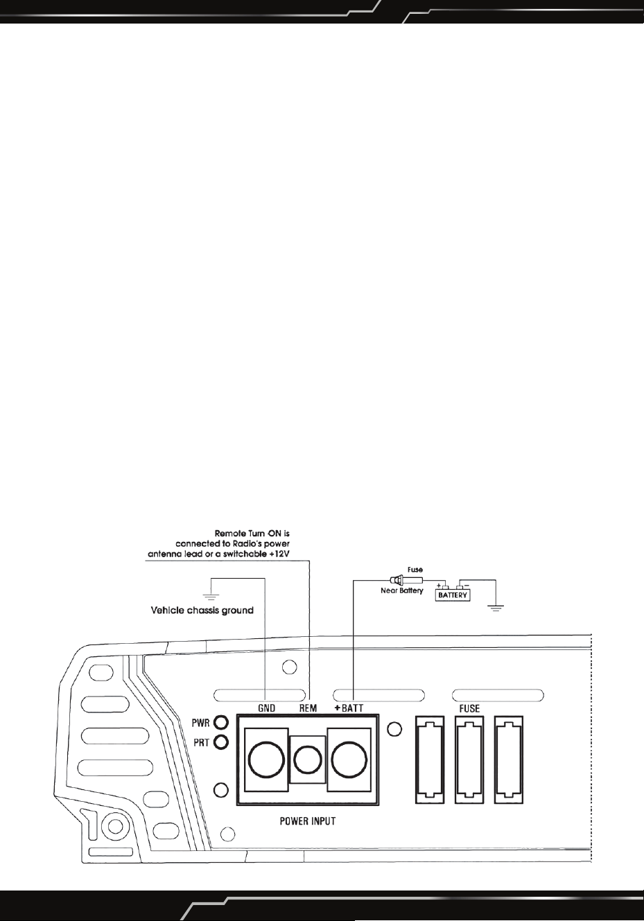
WIRING CONNECTION
1. Ground: To Vehicle Chassis
To avoid unwanted ignition noise caused by ground loop, it is essential that the
Amplier be grounded to a clean, bare, metal surface of the vehicle's Chassis
NOTE:
GROUND WIRE SHOULD NOT BE EXTENDED MORE THAN 3 FT. (1 METER).
2. +12 Volt (Fused) Constant Power: To Battery (+)
Due to the power requirements of the Amplier, this connection should be
made directly to the positive (+) terminal of battery. For safety measures,
install an in-line Fuse Holder (not included) as close to the battery positive (+)
terminal as possible with an ampere rating; not to exceed total value of fuses
in Amp.
3. Remote Turn-On Input: To remote turn-on output of Car Stereo
This Amplier is turned "ON" remotely when the vehicle's stereo is turned "ON".
NOTE:
IF YOUR RADIO DOES NOT HAVEA +12 VOLT OUTPUT LEAD WHEN THE RADIO IS
TURNED ON,THE "REMOTE" TERMINAL ON THE AMPLIFIER CAN BE CONNECTED
TO VEHICLE'S ACCESSORY CIRCUIT THAT IS LIVE WHEN THE KEY lS "ON".
HTG559BT - HTG669BT
www.Lanzar.com
5
HTG889
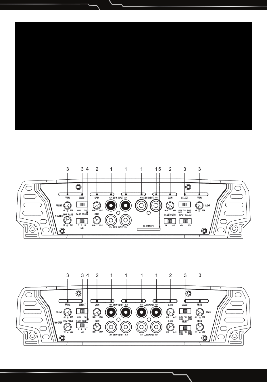
PANEL LAYOUT
HTG559BT - HTG669BT Front View
HTG889 Front View

www.Lanzar.com
6
Rear View
HTG559BT
HTG669BT
HTG889

www.Lanzar.com
7
CONTROL FUNCTIONS
1. RCA Input jacks
These RCA input jacks are for use with source units that have RCA or Line level
outputs. A source unit with a minimum level of 200mV is required for proper
operation. The use of high quality twisted pair cables is recommended to
decrease the possibility of radiated noise entering the system.
2. GAIN Control
The level control will match the ampliers sensitivity to the source units signal
voltage. The Operating range is 200mV minimum to 6V maximum.
CAUTION: Do not run the amplier in high volume for long time, otherwise the
loudspeakers will be damaged.
3. X-OVER (SELECT)
• Full pass x-over switch
When the switch is in the "FuII" position, the full range is bypassed.
• Low pass x-over switch
When the switch is in the "LPF" position, frequencies lower than the low pass
frequency setting are passed.
The frequency can be adjusted between 40Hz and 250Hz.
• High pass x-over switch
When the switch is in the "HPF" position, frequencies higher than the high pass
frequency setting are passed.
The frequency is 40Hz-250Hz
• Band Pass select switch
When the switch is in the "Band Pass" position, the band pass range is by
passed: 50Hz-2.5KHz.
4. Bass BOOST
The boost can be selected among 0dB, 6dB and 12dB.
5. Wireless BT Streaming
Wireless BT receiver.
Warning:
Do not connect a level control knob from other manufacturers to the Remote
Sub Level Control of any amplier. Even though the connectors t properly, the
control knob and connector pin positions may be dierent and the amplier will
be damaged.

www.Lanzar.com
8
6. LED
Will illuminate GREEN to indicate the amplier is on and operating normally,
and will be illuminated RED if the amplier shuts down due to short circuit, DC
oset, or overheating detected by on board protection circuitry.
7. Auxiliary Outputs
The Auxiliary outputs oer LANZAR ampliers easy, unlimited system expansion.
Route RCA's from the line out of the rst amplier to the line input of a second
amplier when using a single source output.
8. GND
Connect this terminal directly to the sheet metal chassis of the vehicle, using
the shortest wire necessary to make this connection. Always use wire of the
same gauge or larger than the (+)12 volt power wire. The chassis connection
point should be scraped free of paint and dirt. Use only quality crimped and/or
soldered connectors at both ends of this wire.
Warning: Do not connect this terminal directly to the vehicle battery ground
terminal or any other factory ground points.
9. Remote Turn On
This terminal turns on the amplier when (+)12 volt is applied to it.
Connect it to the remote turn on lead of the head unit or signal source.
10. (+)12 Volt Power
Connect this terminal through a FUSE or CIRCUIT BREAKER to the positive
terminal of the vehicle battery or the positive terminal of an isolated audio
system battery.
Warning: Always protect this power wire by installing a fuse or circuit breaker
of the appropriate size within 12 inches of the battery terminal connection.
11. FUSE
These fuses protect the amplier against internal electrical damage and are
meant to protect the amplier only. All other power connections should be
fused at the source.
12. SPEAKERS
Connect subwoofers to these terminals.

www.Lanzar.com
9
System Diagrams
5 Channel Systems
HTG559BT

www.Lanzar.com
10
System Diagrams
6 Channel Systems
HTG669BT

www.Lanzar.com
11
System Diagrams

www.Lanzar.com
12
System Diagrams
8 Channel Systems
HTG889

www.Lanzar.com
13
System Diagrams
www.Lanzar.com
14
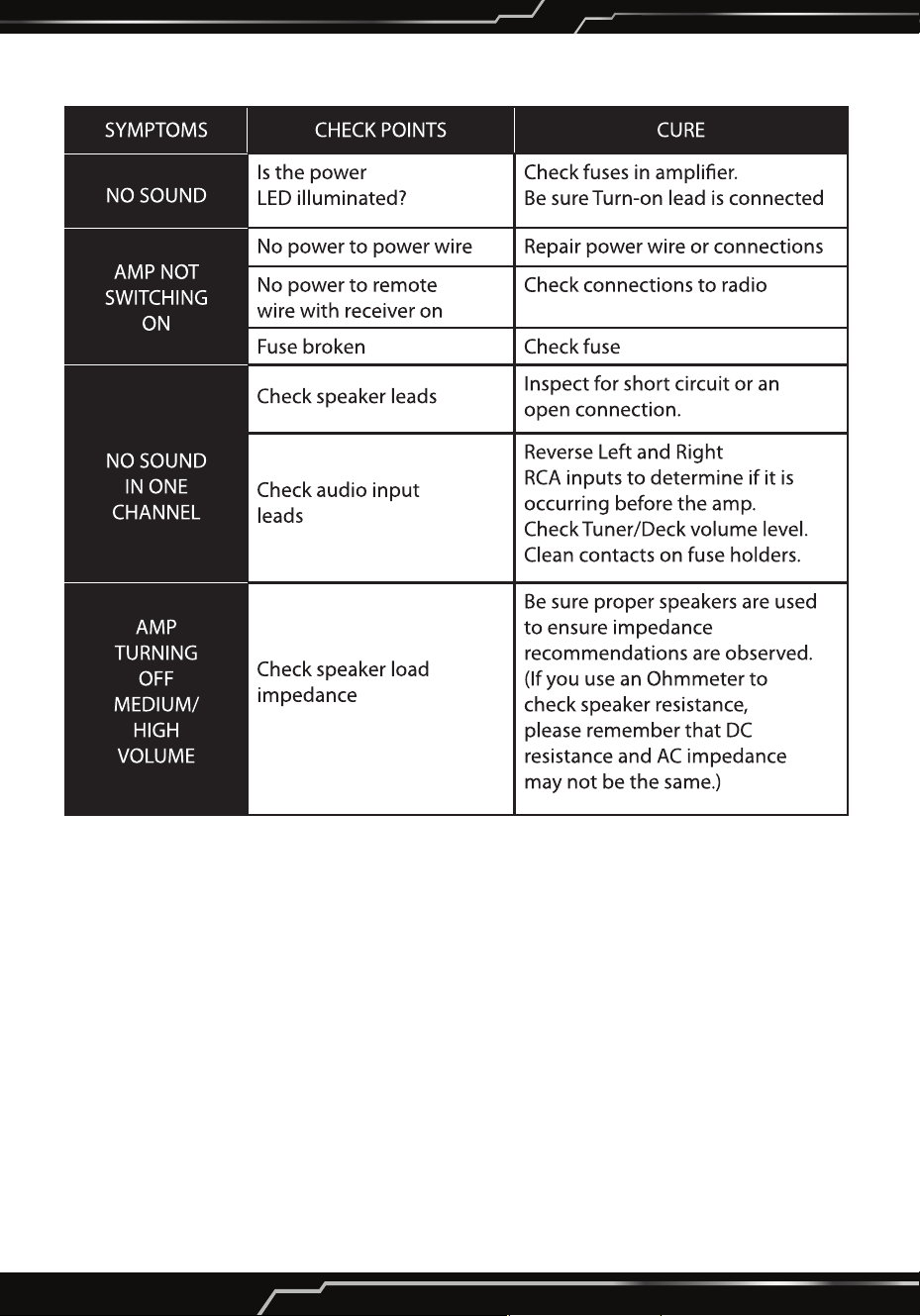
TROUBLESHOOTING GUIDE
WARNINGS
Investigate the layout of your automobile thoroughly before drilling or cutting any
holes. Take care when to work near the gas tanks, lines, or hydraulic lines, and
electrical wiring. Don't use power amplier unmounted. Attach this system securely
to the auto-mobile to prevent damage, particularly in the event of an accident.
Don't mount this system so that the wire connections are unprotected or are
subject to pinching or damage from nearby objects. The +12V DC power wire must
be fused at the battery positive terminal connection. Before making or breaking
power connections at this system power terminals, disconnect the +12V wire at
the battery end. Conrm your radio/cassette player and/or other equip is turned
o while connecting the input jacks and speaker terminals. If you need to replace
the power fuse, replace it only with a fuse identical to that supplied with the system.
Using a fuse of dierent type or rating may result in damage to this system which
isn't covered by the warranty.

www.Lanzar.com
15
Specication
HTG889
8-Channel Mosfet Amplier
2 Ohm Stereo Stable with High Pass and Low Pass Filter Controls
Features:
•
Class “AB” High-Current Dual Discrete Drive Stages
• Mosfet PWM Power Supply
• Bass Boost Circuit
• Bridgeable at 4ohms
• 2 Ohm Stereo Stable
• Chrome RCA Inputs, Power Speaker Terminals
• Stereo Line Outputs for Left and Right Channel
• Low Pass Filter Controls
• High Pass Filter Controls
• Band Pass Filter Controls
• 5 Way Protections
• Power and Protection LED Indicators
• Soft Turn-on/Turn-o
Technical Specs:
•
8 X 250W RMS @ 4 Ohms
• 8 X 350W RMS @ 2 Ohms
• 4 X 1,000W MAX @ 4 Ohms Bridged
• 8 X 500W MAX @ 4 Ohms
• THD: <0.01%
• S/N Ratio: >90dB
• Channel Separation: >65dB
• Freq. Response: 10Hz-45KHz
• LPF Freq. Response: 40Hz-250Hz
• HPF Freq. Response: 40Hz-250Hz
• BPF Freq. Response: 40Hz-3KHz
• Bass Boost(50Hz): 0,6,12dB
• Input Sensitivity: 0.2V~6V
• Fuse: 100A
• Product Dimensions (L x W x H): 22.83'' x 8.81'' x 2.24'' -inches

www.Lanzar.com
16
HTG559BT
5-Channel Mosfet Amplier with Wireless BT Audio Interface
2 Ohm Stereo Stable with High Pass and Low Pass Filter Controls
Features:
•
Wireless BT Audio Interface
• Class “AB” High-Current Dual Discrete Drive Stages
• Mosfet PWM Power Supply
• Bass Boost Circuit
• Bridgeable at 4 Ohms
• 2 Ohm Stereo Stable
• Chrome RCA inputs, Power Speaker Terminals
• Stereo Line Outputs for Left and Right Channel
• Low Pass Filter Controls
• High Pass Filter Controls
• Band Pass Filter Controls
• 5 Way Protections
• Power and Protection LED Indicators
• Soft Turn-on/Turn-o
Technical Specs:
•
4 X 250W + 1 X 650W RMS @ 4 Ohms
• 4 X 350W + 1 X 1,500W RMS @ 2 Ohms
• 2 X 1,000W MAX @ 4 Ohms Bridged
• 4 X 500W + 1 X 2,000W MAX @ 4 Ohms
• THD: <0.01%
• S/N Ratio: >90dB
• Channel Separation: >65dB
• Freq. Response: 10Hz-45KHz
• LPF Freq. Response: 40Hz-250Hz
• HPF Freq. Response: 40Hz-250Hz
• BPF Freq. Response: 40Hz-3KHz
• Bass Boost (50Hz): 0,6,12dB
• Input Sensitivity: 0.2V~6V
• Fuse: 30A X 3
• Product Dimensions (L x W x H): 19.29'' x 8.81'' x 2.24'' -inches

www.Lanzar.com
17
HTG669BT
6-Channel Mosfet Amplier with Wireless BT Audio Interface
2 Ohm Stereo Stable with High Pass and Low Pass Filter Controls
Features:
•
Wireless BT Audio Interface
• Class “AB” High-Current Dual Discrete Drive Stages
• Mosfet PWM Power Supply
• Bass Boost Circuit
• Bridgeable at 4 Ohms
• 2 Ohm Stereo Stable
• Chrome RCA Inputs, Power Speaker Terminals
• Stereo Line Outputs for Left and Right Channel
• Low Pass Filter Controls
• High Pass Filter Controls
• Band Pass Filter Controls
• 5 Way Protections
• Power and Protection LED Indicators
• Soft Turn-on/Turn-o
Technical Specs:
•
6 X 250W RMS @ 4 Ohms
• 6 X 350W RMS @ 2 Ohms
• 3 X 1,000W MAX @ 4 Ohms Bridged
• 6 X 500W MAX @ 4 Ohms
• THD: <0.01%
• S/N Ratio: >90dB
• Channel Separation: >65dB
• Freq. Response: 10Hz-45KHz
• LPF Freq. Response: 40Hz-250Hz
• HPF Freq. Response: 40Hz-250Hz
• BPF Freq. Response: 40Hz-3KHz
• Bass Boost(50Hz) : 0,6,12dB
• Input Sensitivity:0.2V~6V
• Fuse: 25A X 3
• Product Dimensions (L x W x H): 19.29'' x 8.81'' x 2.24'' -inches

Questions? Issues?
We are here to help!
Phone: (1) 718-535-1800
Email: support@lanzar.com