www.stabila.com
How true pro’s measure
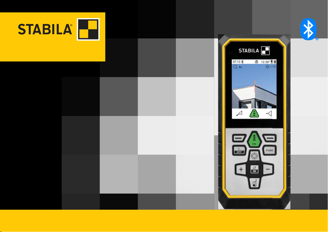
LD 530 BT
Operating instructions
Introduction
This manual contains important safety directions as well as instructions for setting up
the product and operating it. Refer to 1 Safety Directions for further information.
Read carefully through the User Manual before you switch on the product.
The content of this document is subject to change without prior notice. Ensure that the
product is used in accordance with the latest version of this document.
Updated versions are available for download at the following Internet address:
Keep for future reference!
• Bluetooth® is a registered trademark of Bluetooth SIG, Inc.
All other trademarks are the property of their respective owners.
This manual applies to the LD 530 BT. Where there are differences between the standard
setups they are clearly described.
☞
☞
Trademarks
Validity of this manual
2

Table of Contents
1 Safety Directions 4
1.1 General Introduction 4
1.2 Denition of Use 7
1.3 Limits of Use 8
1.4 Responsibilities 8
1.5 Hazards of Use 9
1.6 Laser Classication 12
2 Overview 14
3 Instrument Setup 17
4 Operation 24
5 Settings 29
6 Functions 57
7 Message Codes 77
8 Care 79
9 Technical Data 80
9.1 Conformity to National Regulations 83
3 Table of Contents

1 Safety Directions
1.1 General Introduction
The following directions enable the person responsible for the product, and the person
who actually uses the equipment, to anticipate and avoid operational hazards.
The person responsible for the product must ensure that all users understand these
directions and adhere to them.
Warning messages are an essential part of the safety concept of the instrument. They
appear wherever hazards or hazardous situations can occur.
Warning messages...
•
make the user alert about direct and indirect hazards concerning the use of the
product.
•
contain general rules of behaviour.
For the users‘ safety, all safety instructions and safety messages shall be strictly
observed and followed! Therefore, the manual must always be available to all persons
performing any tasks described here.
DANGER, WARNING, CAUTION and NOTICE are standardised signal words for identify-
ing levels of hazards and risks related to personal injury and property damage. For your
safety, it is important to read and fully understand the following table with the different
signal words and their denitions! Supplementary safety information symbols may be
placed within a warning message as well as supplementary text.
Description
About warning
messages
4 Safety Directions
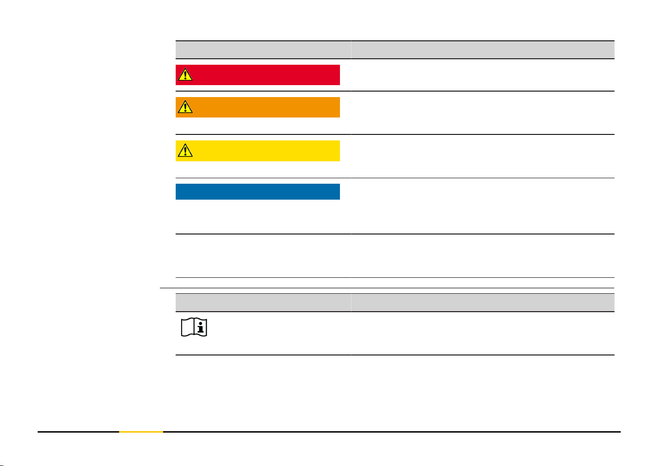
Type Description
DANGER
Indicates an imminently hazardous situation which,
if not avoided, will result in death or serious injury.
WARNING
Indicates a potentially hazardous situation or an
unintended use which, if not avoided, could result
in death or serious injury.
CAUTION
Indicates a potentially hazardous situation or an
unintended use which, if not avoided, may result in
minor or moderate injury.
NOTICE
Indicates a potentially hazardous situation or an
unintended use which, if not avoided, may result
in appreciable material, nancial and environmental
damage.
☞
Important paragraphs which must be adhered to in
practice as they enable the product to be used in a
technically correct and efcient manner.
Symbol Description
Operator's manual.
Instruct the operator to read the user manual and
safety instructions.
Description of symbols
5 Safety Directions
Symbol Description
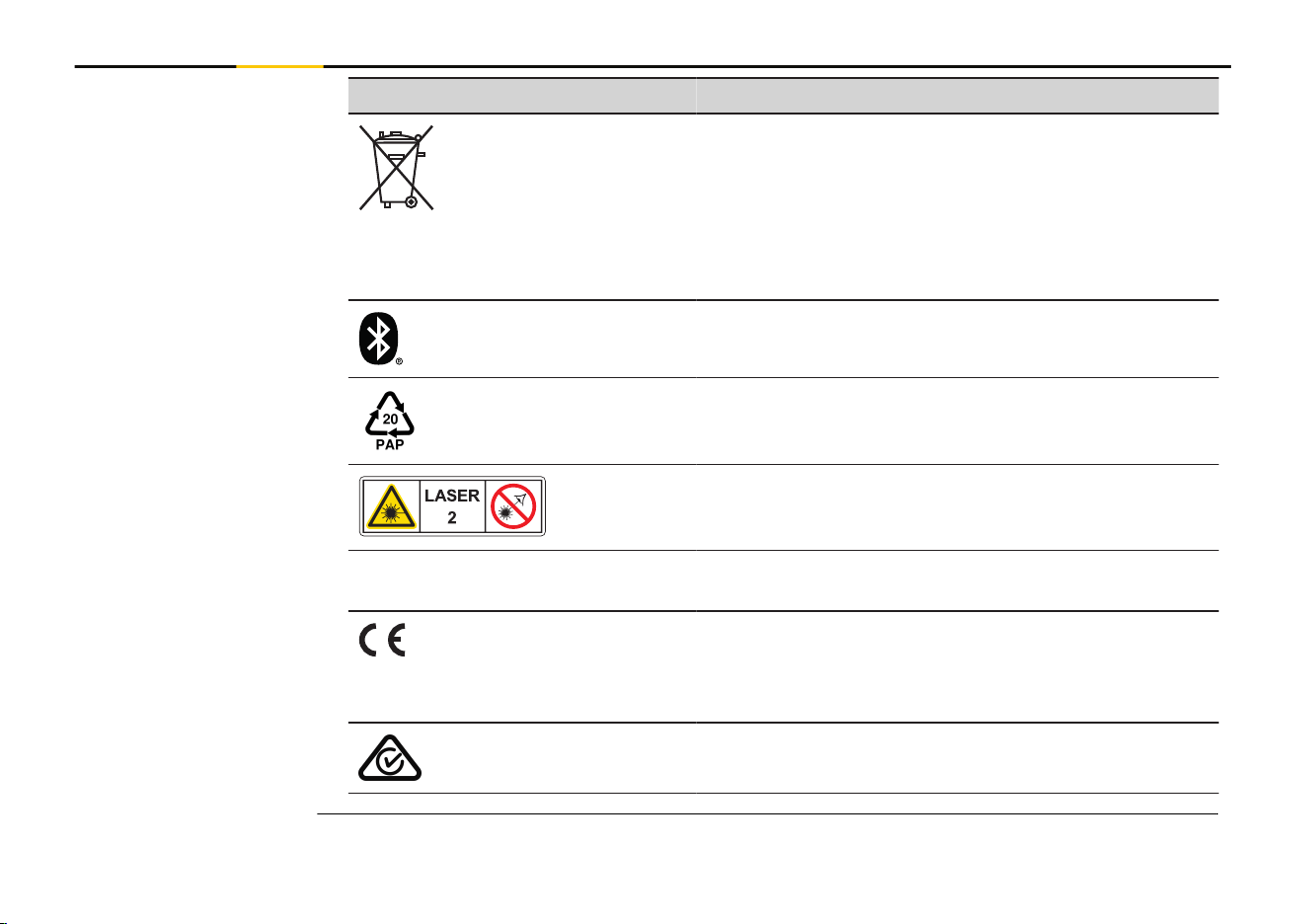
Disposal
In accordance with EU Directive 2012/19/EU on
waste of electrical and electronic equipment and
its implementation in national legislation, non-
usable electrical appliances must be collected sep-
arately and disposed of in an environmentally
friendly manner.
Bluetooth®
Packaging is manufactured using corrugated card-
board.
EU Packaging Waste Directive 97/129/EC.
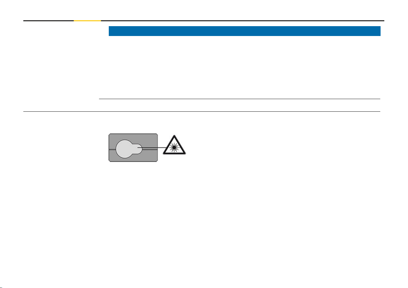
Laser Warning.
Laser class 2 acc. IEC 60825-1.
Do not look into the laser beam.
IP54 IP Class acc. IEC 60529.
Dust- and splash water protected.
CE mark Europe (European Conformity) certifying
that the product complies with essential require-
ments of the EU directives and harmonizes EU
standards.
RCM mark Australia.
6 Safety Directions

1.2 Denition of Use
•
Measuring distances in interior as well as exterior condition
•
Tilt measurement
• Data transfer with Bluetooth®
•
Use of the product without instructions
•
Use outside of the intended use and limits
•
Disabling of safety systems
•
Removal of hazard notices
•
Opening the product using tools, for example a screwdriver, unless this is permitted
for certain functions
•
Modication or conversion of the product
•
Deliberate dazzling of third parties; also in the dark
•
Inadequate safeguards at the working site
•
Deliberate or irresponsible behaviour on scaffold, when using ladders, when measur-
ing near machines which are running or near parts of machines or installations which
are unprotected
•
Aiming directly into the sun
•
Optics are fogged up or wet. Before measurements, condensation moisture and
splash water must be removed from directly accessible parts such as the output
optics using a suitable cloth
•
Moving the device during measurements. Try to hold it still when measuring
•
Dusty atmosphere. Make sure that the lenses of the instrument are free of dust
when measuring. If necessary, clean with a brush
•
Measurements in rain, snow, fog or other atmospheric conditions between the
device and the target point
Intended Use
Foreseeable misuse
7 Safety Directions

•
Measurements in strong electrical and magnetic elds, which cannot be completely
ruled out in the vicinity of transformers, strong magnets, power supply systems, and
so on
•
Measurements with the laser beam in the immediate vicinity of highly reective
surfaces
1.3 Limits of Use
☞
Refer to section 9 Technical Data.
Suitable for use in an atmosphere appropriate for permanent human habitation. Not
suitable for use in aggressive or explosive environments.
1.4 Responsibilities
STABILA Messgeräte Gustav Ullrich GmbH, D-76855 Annweiler, hereinafter referred to as
STABILA, is responsible for supplying the product, including the User Manual and original
accessories, in a safe condition.
The company above is not responsible for third-party accessories.
The person responsible for the product has the following duties:
•
To understand the safety instructions on the product and the instructions in the
User Manual
•
To be familiar with local safety regulations relating to accident prevention
•
Always prevent access to the product by unauthorised and/or untrained personnel
•
To ensure that the product is used in accordance with the instructions
•
Keep the User Manual and pass on if the instrument is passed on
Environment
Manufacturer of the
product
Person responsible for
the product
8 Safety Directions

•
Do not let children use the laser device unsupervised
☞
The product is permitted to use for skilled persons only.
1.5 Hazards of Use
WARNING
Use of product with radio or digital cellular phone devices
Electromagnetic elds can cause disturbances in other equipment, installations, medical
devices, for example pacemakers or hearing aids, and aircrafts. Electromagnetic elds can
also affect humans and animals.
Precautions:
▶
Although the product meets the strict regulations and standards which are in force
in this respect, STABILA cannot completely exclude the possibility that other equip-
ment can be disturbed or that humans or animals can be affected.
▶
Do not operate the product with radio or digital cellular phone devices in the vicinity
of lling stations or chemical installations, or in other areas where an explosion
hazard exists.
▶
Do not operate the product with radio or digital cellular phone devices near medical
equipment.
▶
Do not operate the product with radio or digital cellular phone devices in aircrafts.
▶
Do not operate the product with radio or digital cellular phone devices for long
periods with the product immediately next to your body.
☞
This warning also applies when using products with Bluetooth.
Radios, digital cellular
phones or products
with Bluetooth
9 Safety Directions
WARNING
Improper disposal of product
If the product is improperly disposed of, the following can happen:
•
If polymer parts are burnt, poisonous gases are produced which may impair health.
•
If batteries are damaged or are heated strongly, they can explode and cause poison-
ing, burning, corrosion or environmental contamination.
•
By disposing of the product irresponsibly you may enable unauthorised persons to
use it in contravention of the regulations, exposing themselves and third parties to
the risk of severe injury and rendering the environment liable to contamination.
Precautions:
▶
The product must not be disposed with household waste.
Dispose of the product appropriately in accordance with the
national regulations in force in your country.
Always prevent access to the product by unauthorised personnel.
10 Safety Directions
CAUTION
Electromagnetic radiation
Electromagnetic radiation can cause disturbances in other equipment.
Precautions:
▶
Although the product meets the strict regulations and standards which are in force
in this respect, STABILA cannot completely exclude the possibility that other equip-
ment may be disturbed.
▶
The product is a class A product when operated with the internal batteries. In a
domestic environment this product may cause radio interference in which case the
user may be required to take adequate measures.
NOTICE
Dropping, misusing, modifying, storing the product for long periods or transport-
ing the product
Watch out for erroneous measurement results.
Precautions:
▶
Periodically carry out test measurements, particularly after the product has been
subjected to abnormal use and before and after important measurements.
11 Safety Directions
NOTICE
Target surfaces
Measuring errors and increase of measuring time can occur.
Precautions:
▶
Keep in mind that measuring errors can occur when measuring to colourless liquids,
glass, styrofoam or permeable surfaces or when aiming at high gloss surfaces.
▶
Against dark surfaces the measuring time increases.
1.6 Laser Classication
The laser LED built into the product produces a visible laser beam which emerges from
the front side.
The laser product described in this section is classied as laser class 2 in accordance
with:
•
IEC 60825-1 (2014-05): “Safety of laser products”
These products are safe for momentary exposures but can be hazardous for deliberate
staring into the beam. The beam may cause dazzle, ash-blindness and after-images,
particularly under low ambient light conditions.
General
12 Safety Directions
CAUTION
Class 2 laser product
From a safety perspective, class 2 laser products are not inherently safe for the eyes.
Precautions:
▶
Avoid staring into the beam or viewing it through optical instruments.
▶
Avoid pointing the beam at other people or at animals.
▶
Pay particular attention to the direction of the laser beam when remotely operating
the product by an app or software. A measurement could be triggered at any time.
▶
If laser radiation hits your eye, you must close your eyes and immediately turn your
head away from the beam.
Description Value
Wavelength 635 nm
Maximum peak radiant output power < 1 mW
Pulse duration < 1 ns
Pulse repetition frequency (PRF) 320 MHz
Beam divergence 0.9 mrad
13 Safety Directions
2 Overview
The LD 530 BT is a laser distance meter operating with a class 2 laser.
See chapter 9 Technical Data for scope of use.
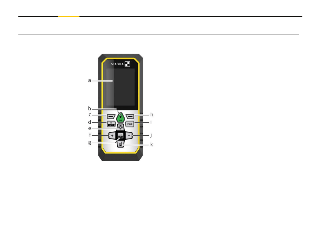
a Display
b
ON, ON/Measure
c Left selection key linked to symbols above
d Clear/OFF
e Pointnder/Zoom/Navigate upwards
f Add/Navigate left
g Enter/Equal
h Right selection key linked to symbols above
i FUNC – Function/Settings
j Subtract/Navigate right
k Measuring reference/Navigate downwards
Components
14 Overview
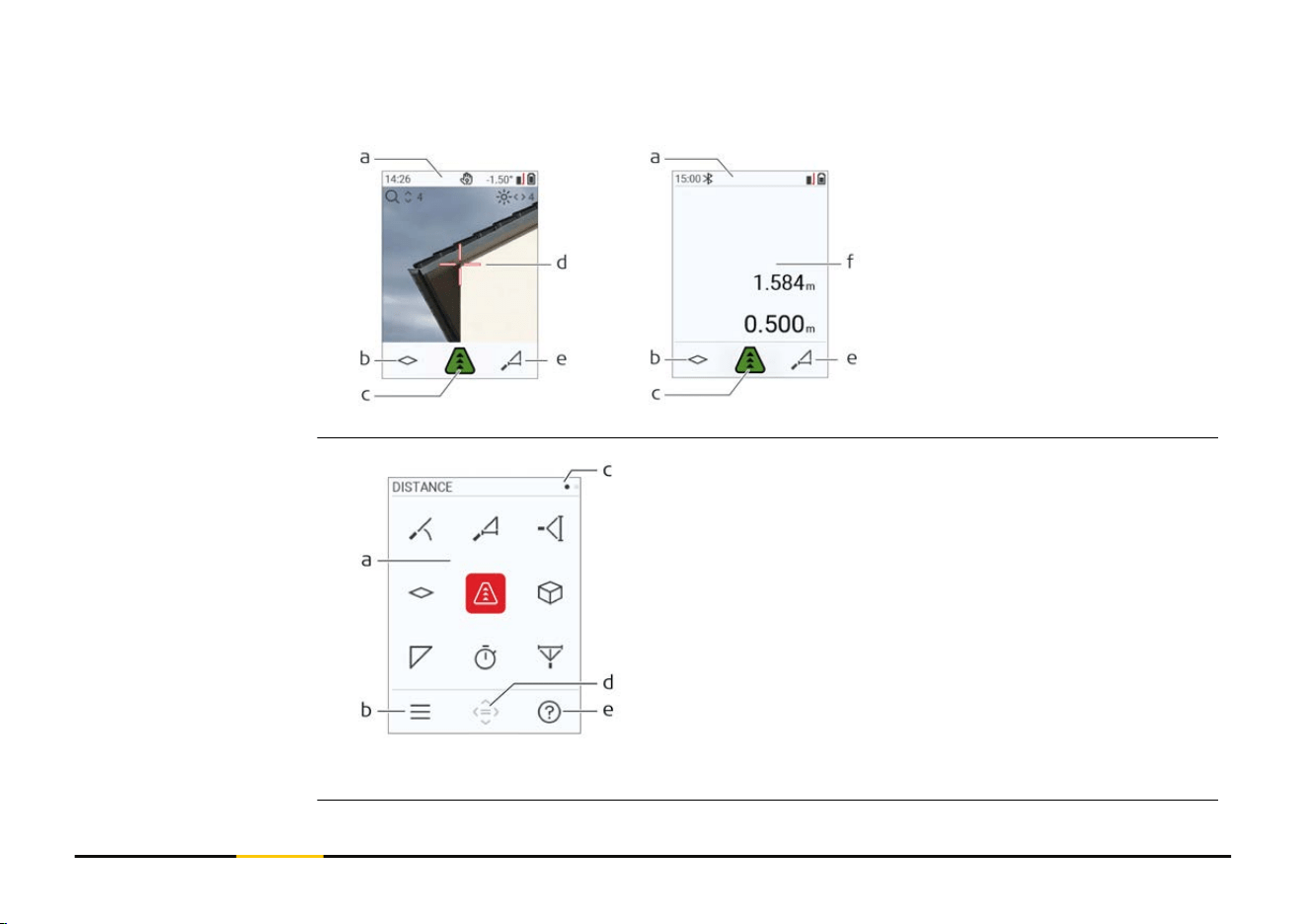
Pointnder on Pointnder off
a Status bar
b
Favourite, left key
c Active function
d Cross hair
e Favourite, right key
f Measuring results
a Function/Settings menu
b
Press the "Left selection" key to switch
between Function/Settings menu.
Option: Press "FUNC" key twice
c Page indicator.
Press "Navigate left/right" key
d Selects the indicated icon.
Press the "Enter/Equal" or "ON" key
e Help function. Press the "Right selection"
key to see available help
☞
Red icons represent Functions.
Black icons represent Settings.
Basic measuring screen
Selection screen
15 Overview
a Back step-by-step.
For example: Repeat measurement
b Repeat function
For example: Repeat whole measurement
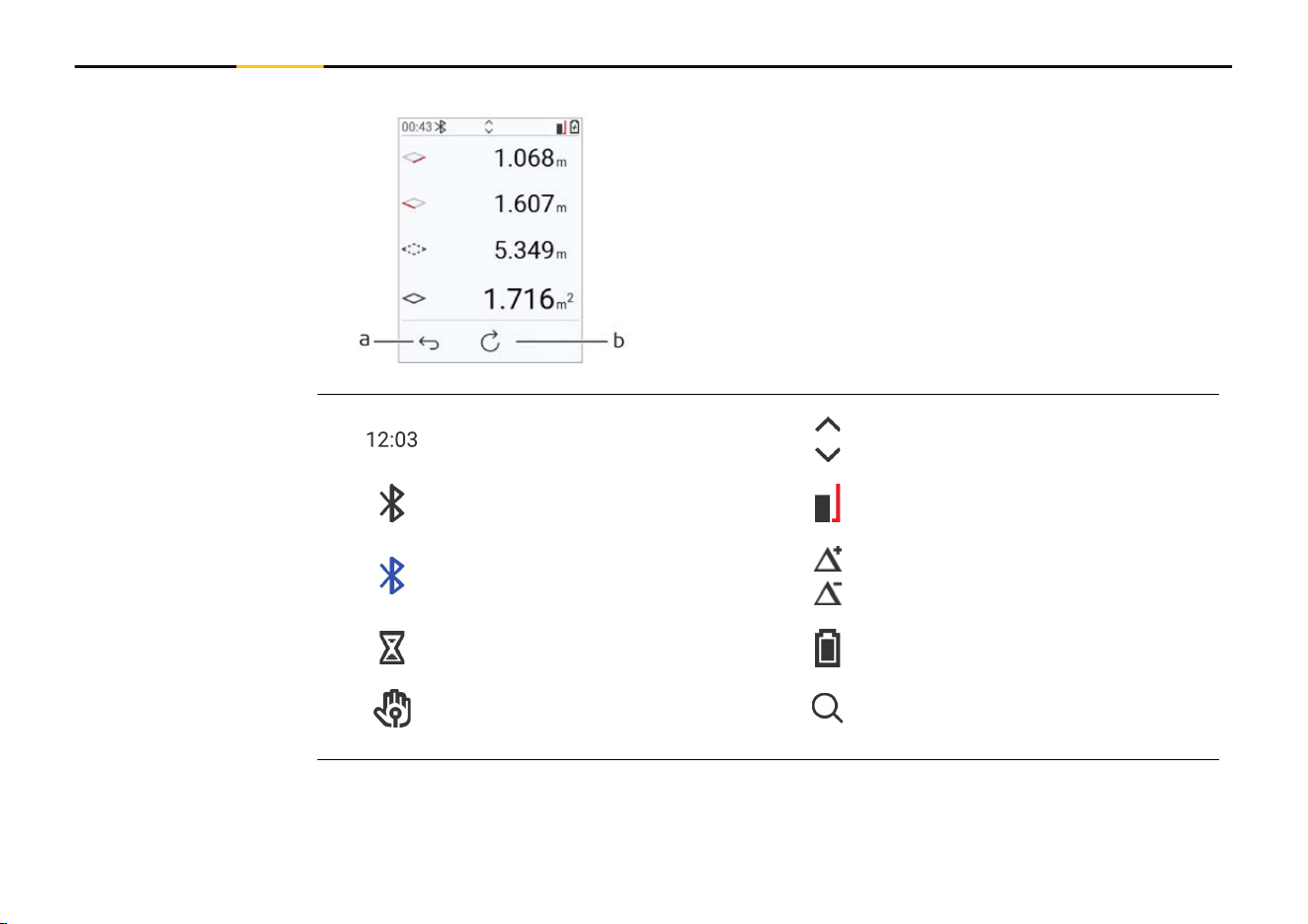
Time Scroll up/down for further results
Bluetooth is switched on Measuring reference
Bluetooth connection established
Offset is activated and adds/sub-
stracts the dened value from
measuring distance
Device is measuring Battery power
Gesture control Zoom
Basic result screen
Icons on status bar
16 Overview
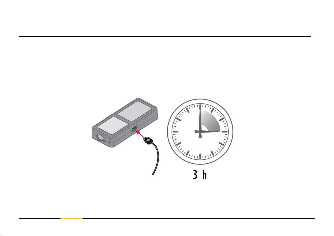
3 Instrument Setup
Charge the battery before using it for the rst time.
☞
Use the original charging cable only.
Plug the small end of the cable into the port of the device, and plug the end of the
charger into an electrical socket. Select the appropriate connector for your country. The
device can be used while charging.
Using the computer for charging the device is possible if the USB port is providing suf-
cient power. We therefore recommend the use of a USB charging device with 5 V/1 A.
Charging the Li-Ion
battery by USB
17 Instrument Setup
•
The battery must be charged before using it the rst time, because it is delivered
with an energy content as low as possible.
•
The permissible temperature range for charging is from 5 °C to +40 °C/+41 °F
to +104 °F. For optimal charging, we recommend charging the batteries at a low
ambient temperature of +10 °C to +20 °C/+50 °F to +68 °F if possible
•
It is normal for the battery to become warm during charging. Using the chargers
recommended by STABILA, it is not possible to charge the battery once the temper-
ature is too high
•
For new batteries or batteries that have been stored for a long time (> three
months), it is effectual to make a discharge/charge cycle
•
For Li-Ion batteries, a single discharge/charge cycle is sufcient. We recommend
carrying out the process when the battery capacity indicated on the charger or on a
STABILA product deviates signicantly from the actual battery capacity available.
CAUTION
The device shows the message code 298
Internal diagnostics indicate a possible swell of the Li‑Ion battery.
Precautions:
▶
Switch off and stop using the device.
▶
Replace the battery before using the device again.
18 Instrument Setup
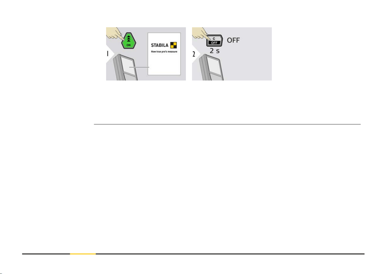
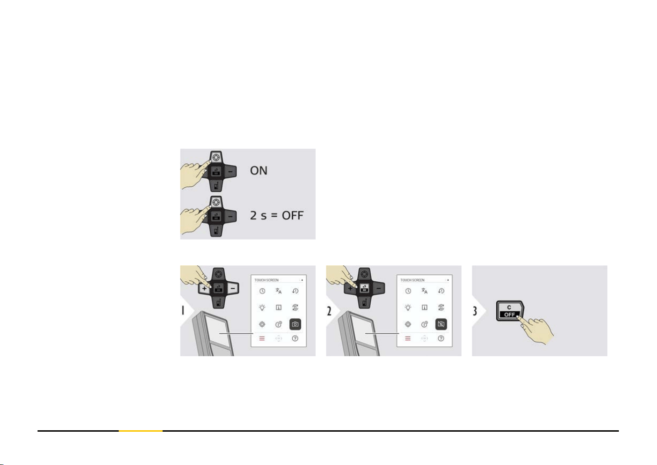
Device is turned ON.
Device is turned OFF.
☞
If the device does not react anymore or cannot be switched OFF, press and
hold the "C/OFF" key for about 10 s. After releasing the button, the device
restarts.
Switching ON/OFF
19 Instrument Setup
NOTICE
If the message "i" appears with a number, observe the instructions in 7 Message Codes
section.
Example:
☞
When measuring with 90° ipped-out endpiece, make sure that it lies plane
against the edge you measure from. Example:
☞
The orientation of the endpiece is automatically detected and the zero point is
adjusted accordingly.
Message codes
Multifunctional end-
piece
22 Instrument Setup
☞
Adjusting the measuring reference only works
in pointing mode. Make sure that the laser is
switched on.
a Distance is measured from the rear of the device
(standard setting)
b
Distance is measured from the front of the device
c Distance is measured from the tripod thread
Conrm setting.
☞
If device is switched off, reference goes back to standard setting (rear of the
device).
Adjusting measuring
reference
23 Instrument Setup
4 Operation
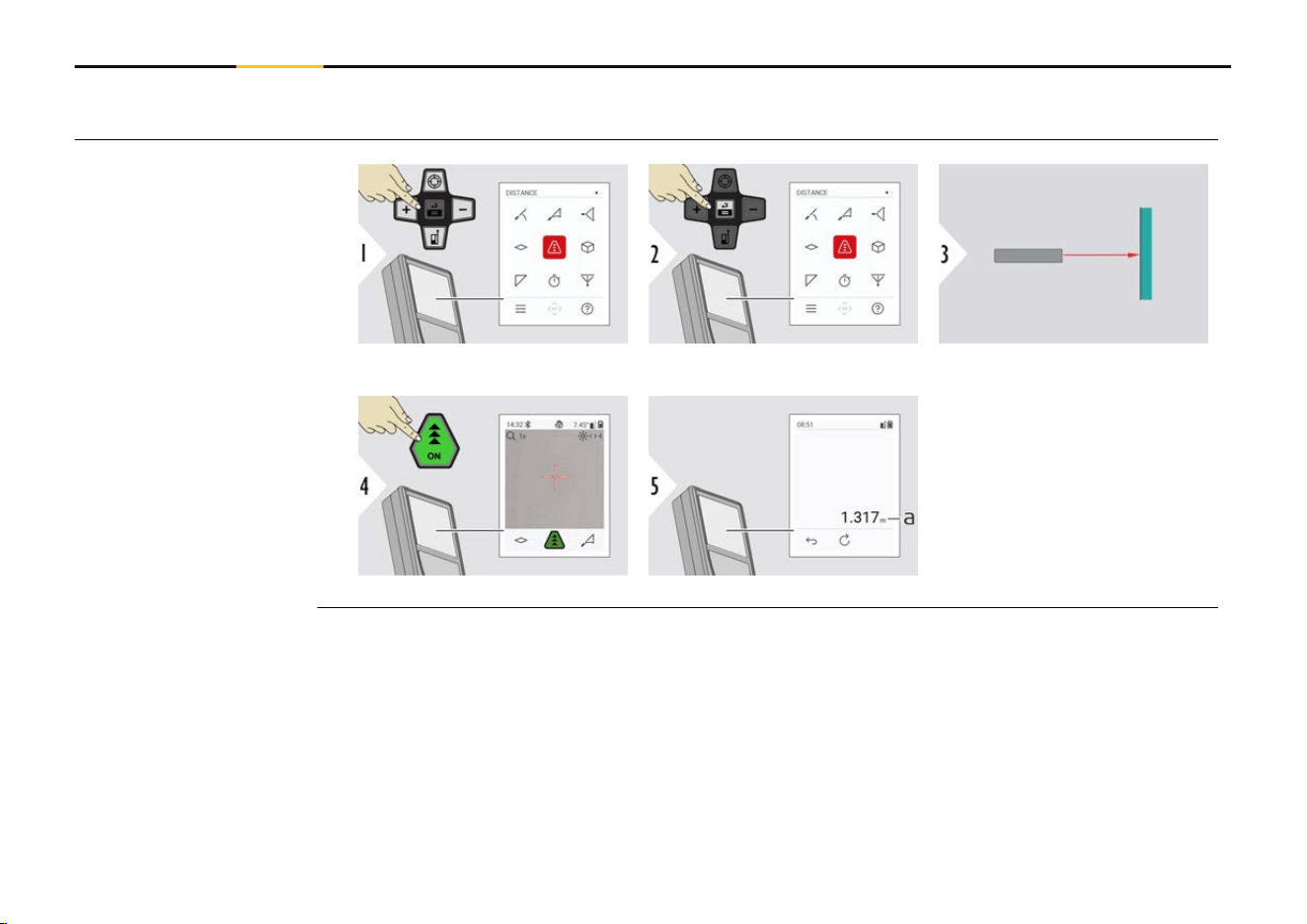
Aim active laser at target.
a Measured distance
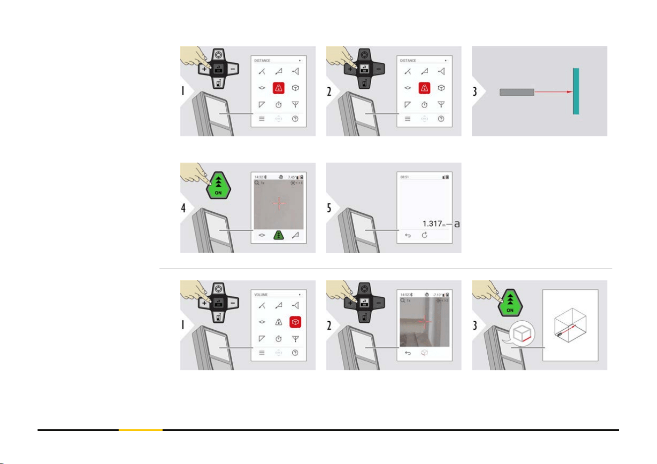
Single DISTANCE
24 Operation
Used to measure room
diagonals (maximum val-
ues) or horizontal distance
(minimum values).
Live view
a The minimum distance measured
b
The maximum distance measured
c Main line: The current value measured
Stops permanent/minimum-maximum measuring.
The measuring results are displayed.
Permanent/minimum-
maximum measuring
25 Operation
☞
Use the "Navigate downwards" key to show
more values.
Exit
26 Operation
+ The next measure-
ment is added to
the previous one
−
The next measure-
ment is subtracted
from the previous
one
Press the "Enter/Equal" key to stop adding/substracting
values.
☞
This process can be repeated as required. The same process can be used for
adding or subtracting areas or volumes.
Add/subtract
27 Operation
☞
Bluetooth is active when the device is switched on. Connect the device with
your smartphone, tablet, laptop... If Autosend is activated, measurement val-
ues are transferred automatically right after a measurement. To transfer a
result, press the Enter/Equal key:
Refer to BLUETOOTH SETTINGS for details.
When connected to an iOS device, press + or − key for 1 second to let the
keyboard appear on the display of your mobile device. Pressing one of those
keys again closes the keyboard.
Bluetooth switches off as soon as the laser distance meter is switched off.
The LD 530 BT is compatible to smartphone, tablet or laptop devices using Bluetooth 4.0
or higher. The number of possible measurements with only one battery charge is hardly
affected due to the Low Energy technology.
Following software and app are available from STABILA. They extend the possibilities
arising with the use of LD 530 BT:
STABILA Measures II. Use App for Bluetooth data transfer. Your device can also be
updated through this App.
Bluetooth data trans-
fer
28 Operation
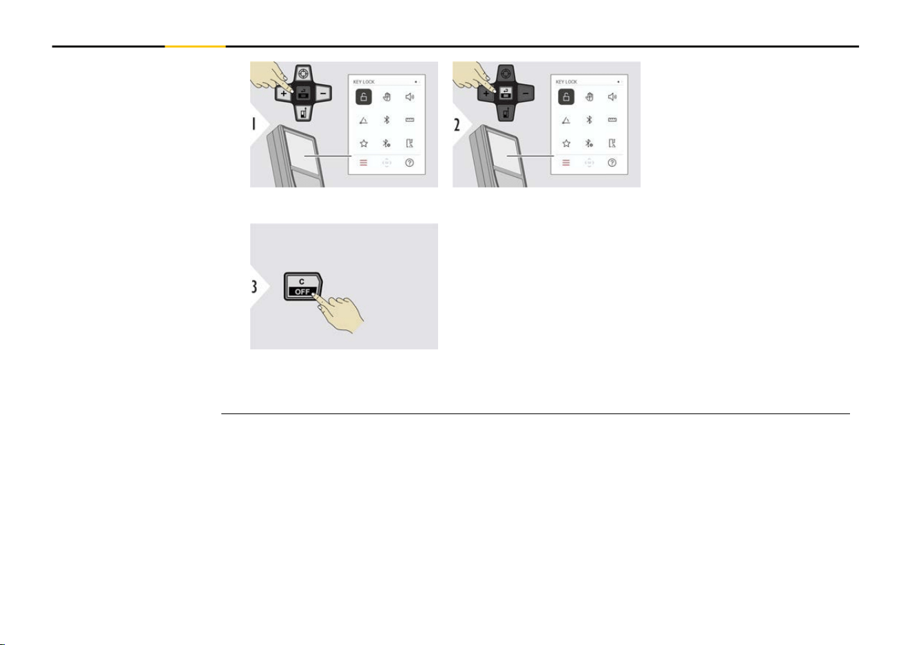
Toggle ON/OFF
An activated key lock stays
active even if the device is
switched off.
Exit settings.
☞
If KEY LOCK is activated:
Press the "Enter/Equal" key after device is switched on to access device.
Activate/deactivate
KEY LOCK
32 Settings
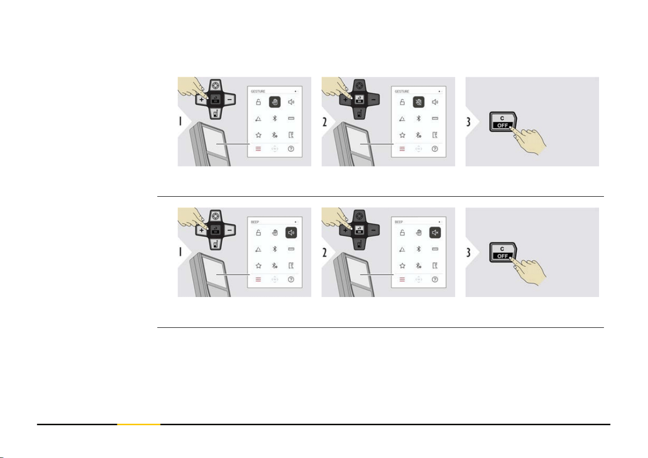
This feature allows triggering measurements without touching the device. To do so, wipe
through laser beam with hand or other object within 5 to 25 cm.
Toggle ON/OFF
Exit settings.
Toggle ON/OFF
Exit settings.
GESTURE ON/OFF
BEEP ON/OFF
33 Settings
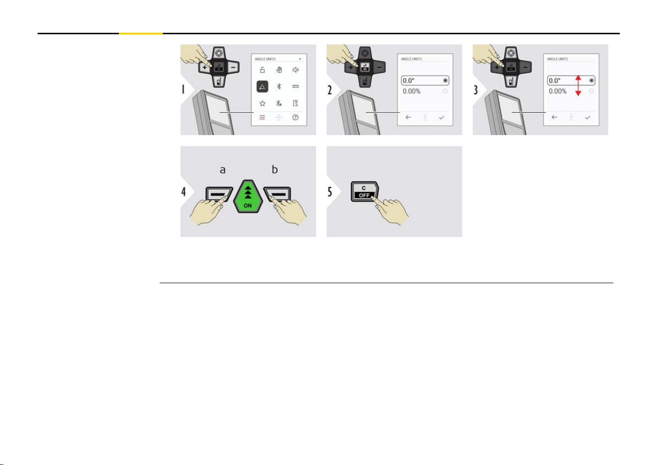
a Refuse
b Conrm
Exit settings.
ANGLE UNITS
34 Settings
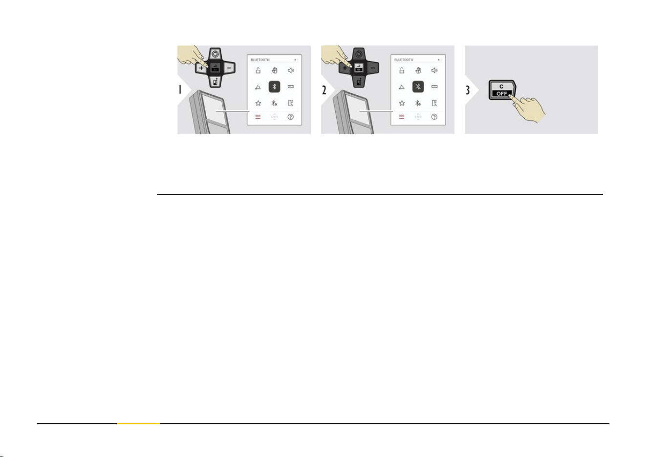
Toggle ON/OFF Exit settings.
☞
When Bluetooth is switched on, a black Bluetooth icon is displayed in status
bar. Once connection is established, the colour of the icon changes to blue.
BLUETOOTH ON/OFF
35 Settings
Toggle between the units.
Example
Conrm setting.
Exit settings.
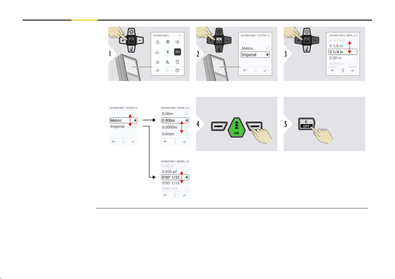
DISTANCE UNITS
36 Settings
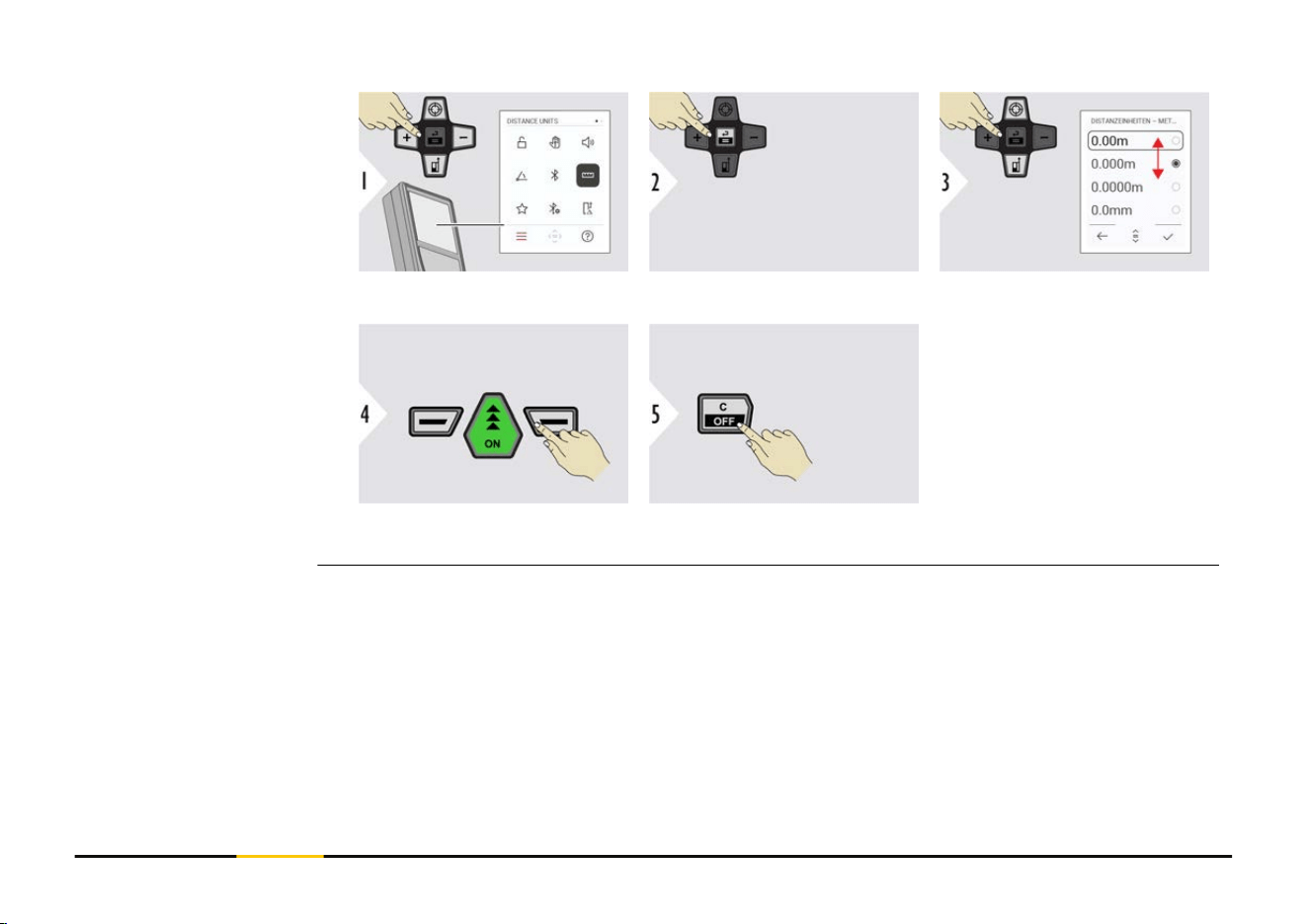
Toggle between the units.
Conrm setting.
Exit settings.
DISTANCE UNITS
37 Settings
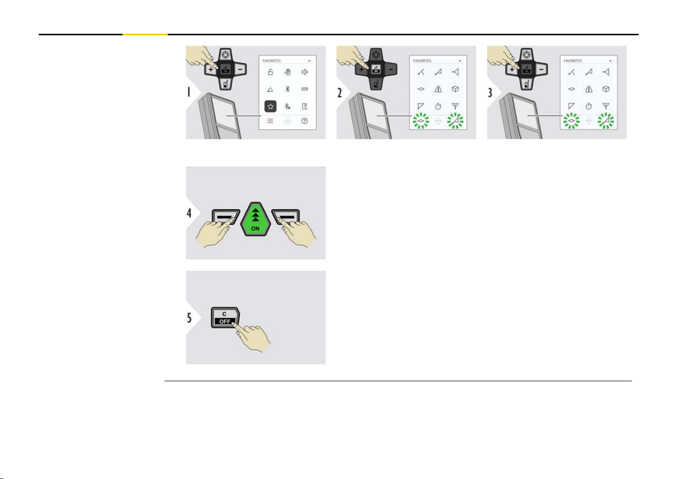
Select favourite function.
Press the "Left slection" or "Right selection" key. Func-
tion is set as favourite above the corresponding selec-
tion key.
Exit settings.
FAVORITES
38 Settings
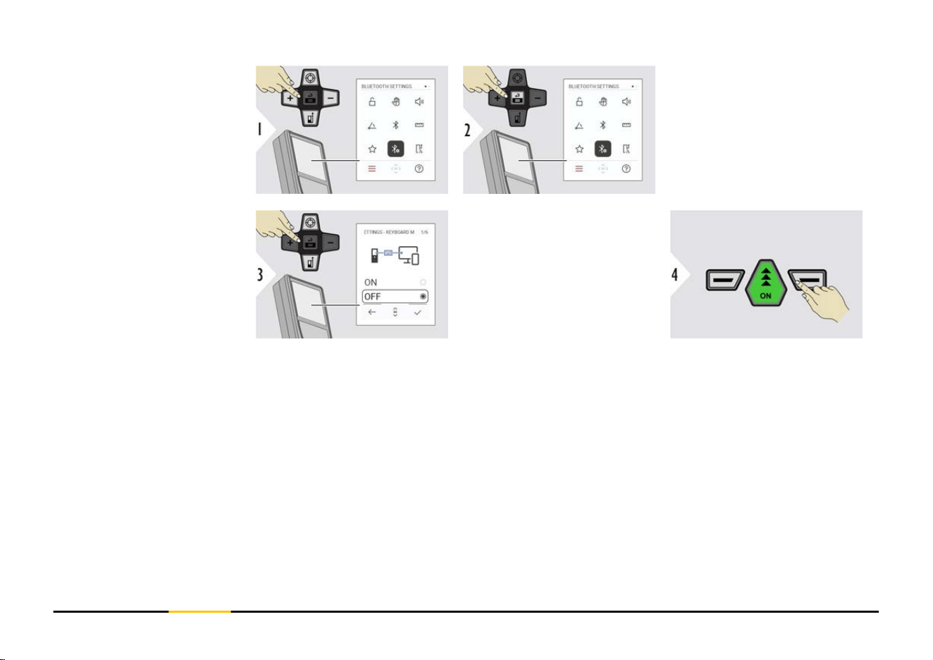
BT SETTINGS -
KEYBOARD MODE
Select ON or OFF.
Enables measurements to
be transmitted as entered
on an external keyboard
to a computer, tablet or
smartphone.
Conrm setting.
BLUETOOTH SETTINGS
39 Settings

BT SETTINGS -
BT NAVIGATION
If activated, it is possible
to send measurements
manually by using the
"Right selection" key. The
"Left selection" key allows
switching on/off the arrow
keys for navigation.
1)
Conrm setting.
BT SETTINGS -
DECIMAL SEPARATOR
Select kind of decimal
point for transmitted value.
Conrm setting.
1)
For example, move between cells when working with Microsoft Excel. A long press/
hold of the corresponding selection key, starts the function as shown on the display
(grey colour).
40 Settings
BT SETTINGS -
UNITS TRANSFER
Select if unit is transmitted
or not.
Conrm setting.
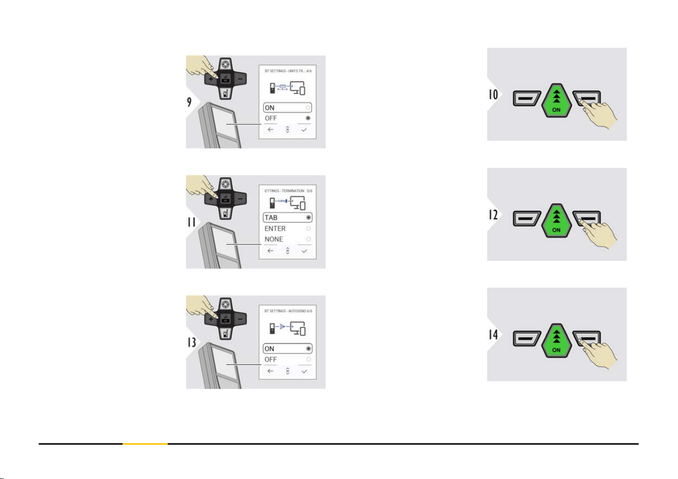
BT SETTINGS -
TERMINATION AFTER
VALUE
Select termination of
transmission.
Conrm setting.
BT SETTINGS -
AUTOSEND
Select if value is transmit-
ted automatically or manu-
ally.
Conrm setting.
41 Settings
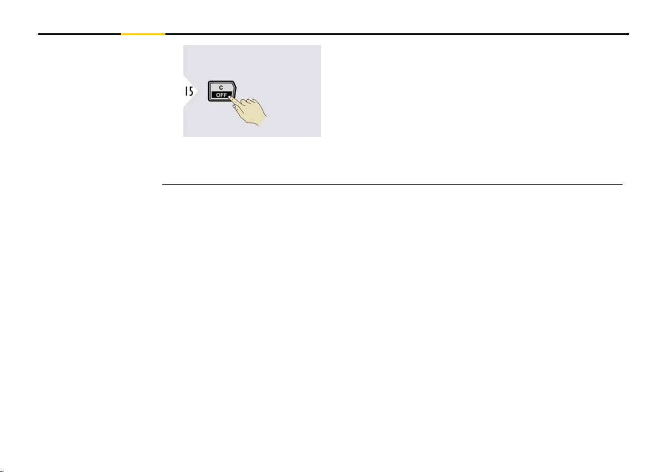
Exit settings.
☞
Depending on the chosen settings for Keyboard mode and Autosend, some
selection points might be skipped.
42 Settings
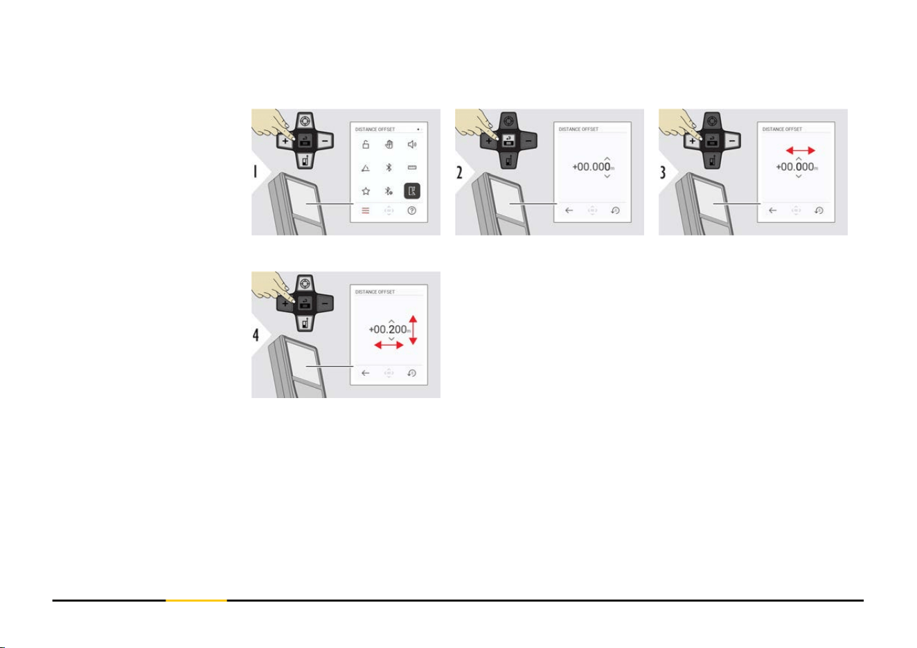
An offset adds or subtracts a specied value automatically to or from all measurements.
This function allows tolerances to be taken into account. The offset icon is displayed.
Select digit.
Adjust digit.
DISTANCE OFFSET
43 Settings
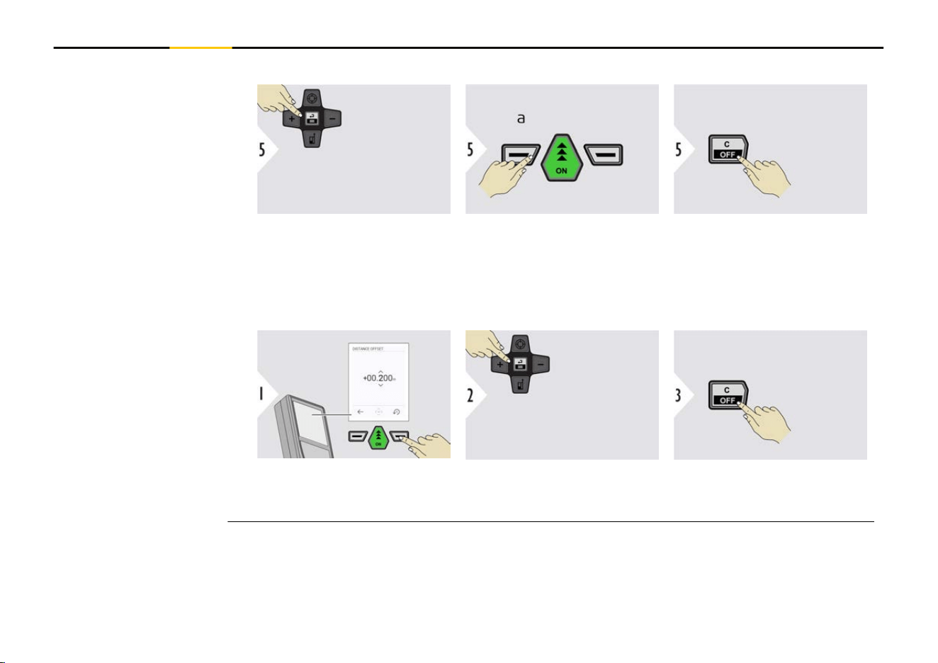
Options:
Accept and activate offset
values.
a Ignore new entered
offset values and
exit menu
Exit menu DISTANCE OFF-
SET function.
Deactivate DISTANCE OFFSET function
Reset any offset values.
Accept offset values = 0.
Exit menu DISTANCE OFF-
SET function.
44 Settings
Conrm setting.
Conrm setting.
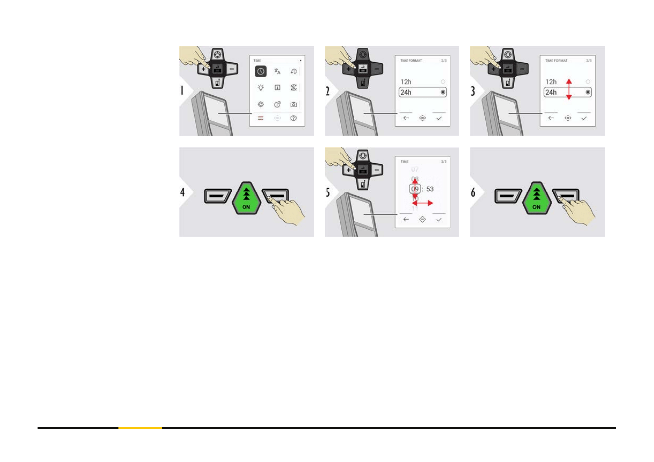
TIME
45 Settings
Conrm setting.
Exit settings.
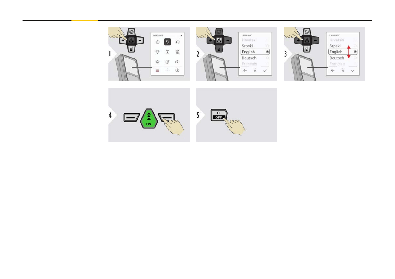
LANGUAGE
46 Settings
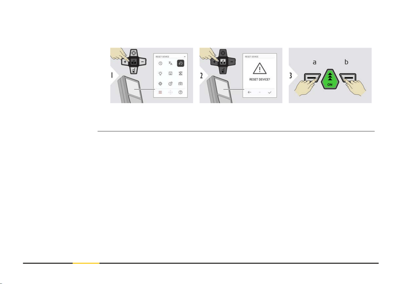
Reset returns the instrument to the factory settings. All customised settings and memor-
ies are lost.
a Refuse
b Conrm
RESET DEVICE
47 Settings
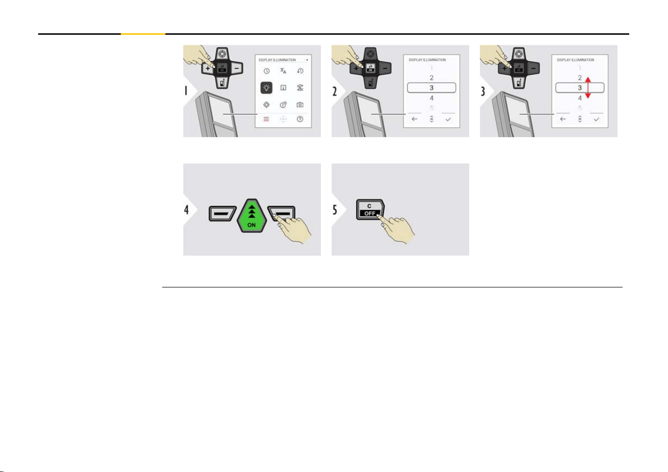
Select brightness.
Conrm setting.
Exit settings.
☞
To save power,
reduce bright-
ness if not
necessary.
DISPLAY ILLUMINATION
48 Settings
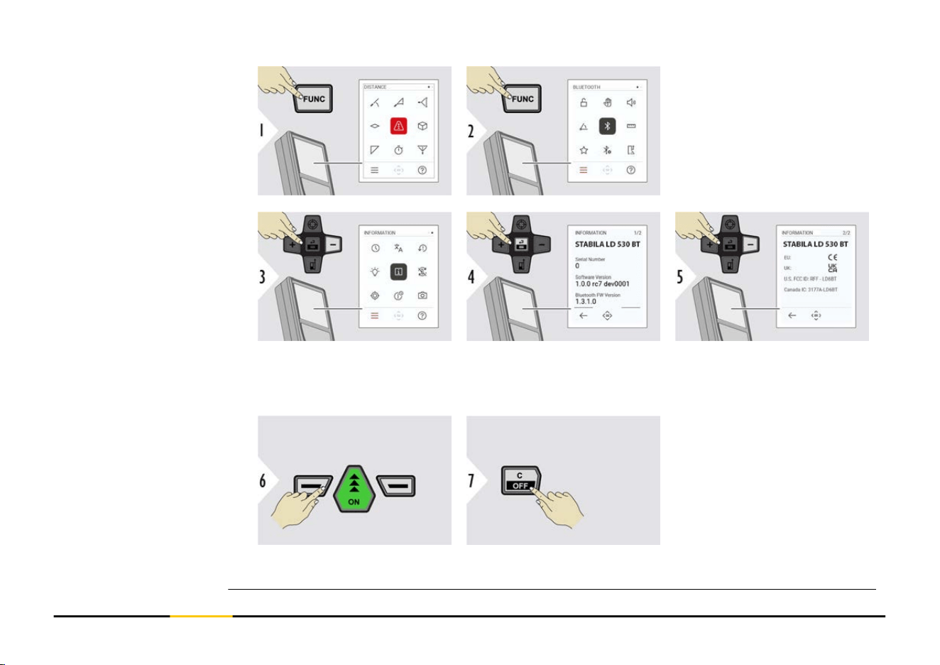
Press the "FUNC" key twice
to enter the settings menu.
Press the "−" key three
times to move to
INFORMATION.
Press the "=" key to access
the INFORMATION.
Press the "−" key to show
the INFORMATION con-
tent.
Exit information screen.
Exit settings.
INFORMATION
49 Settings

Toggle ON/OFF
Exit settings.
Example
SCREEN ROTATION
50 Settings
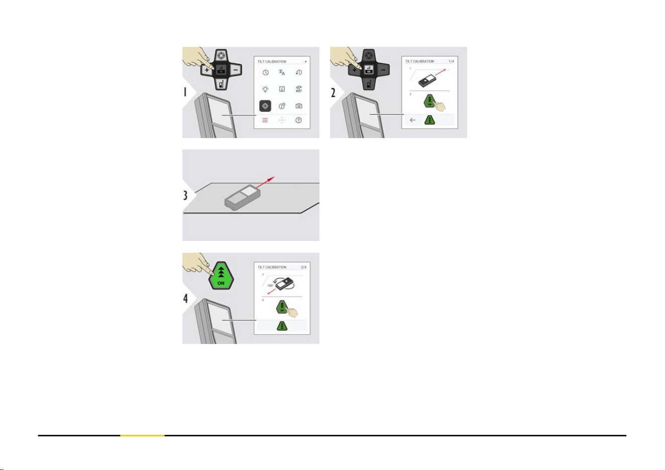
Follow the instructions on
the screen.
Place device on absolutely at surface.
Once nished, press the "ON" key.
Follow the instructions on the screen.
TILT CALIBRATION
51 Settings
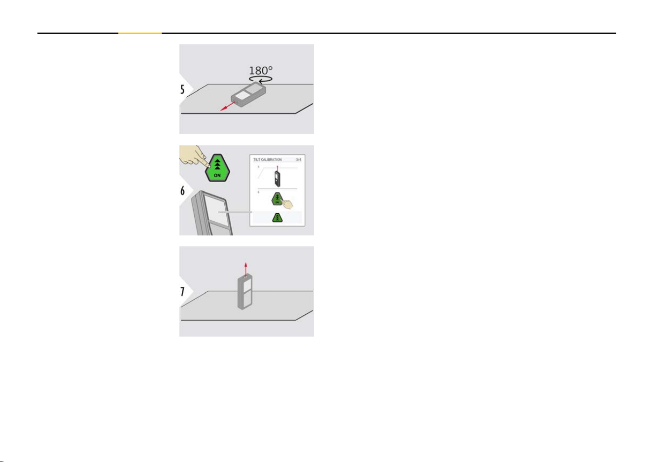
Turn the device horizontally by 180° and place it again
on absolutely at surface.
Once nished, press the "ON" key.
Follow the instructions on the screen.
Place device on absolutely at surface.
52 Settings
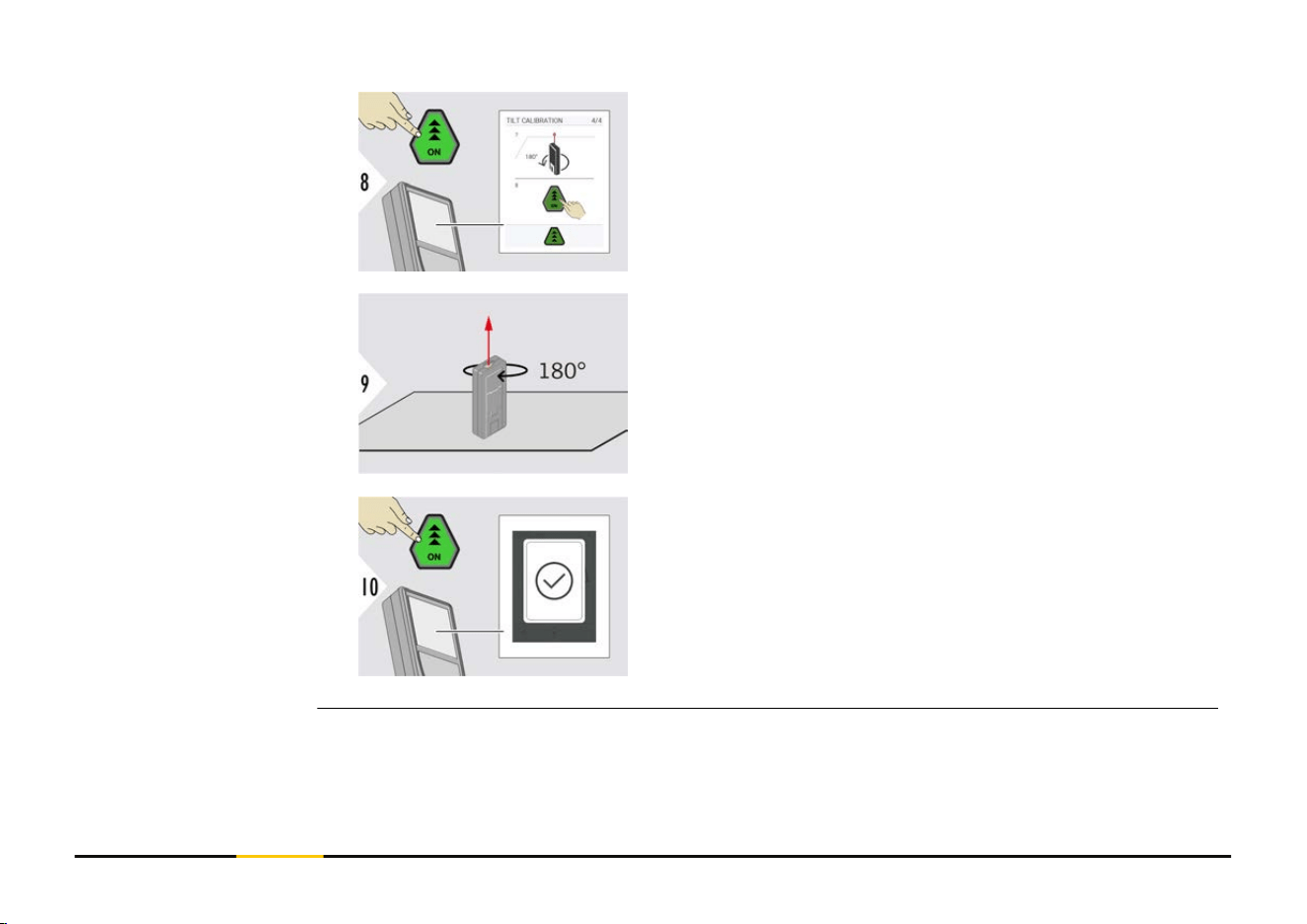
Once nished, press the "ON" key.
Follow the instructions on the screen.
Turn the device horizontally by 180° and place it again
on absolutely at surface.
Once nished, press the "ON" key.
☞
After 2 s, the device goes back to the basic
mode.
53 Settings
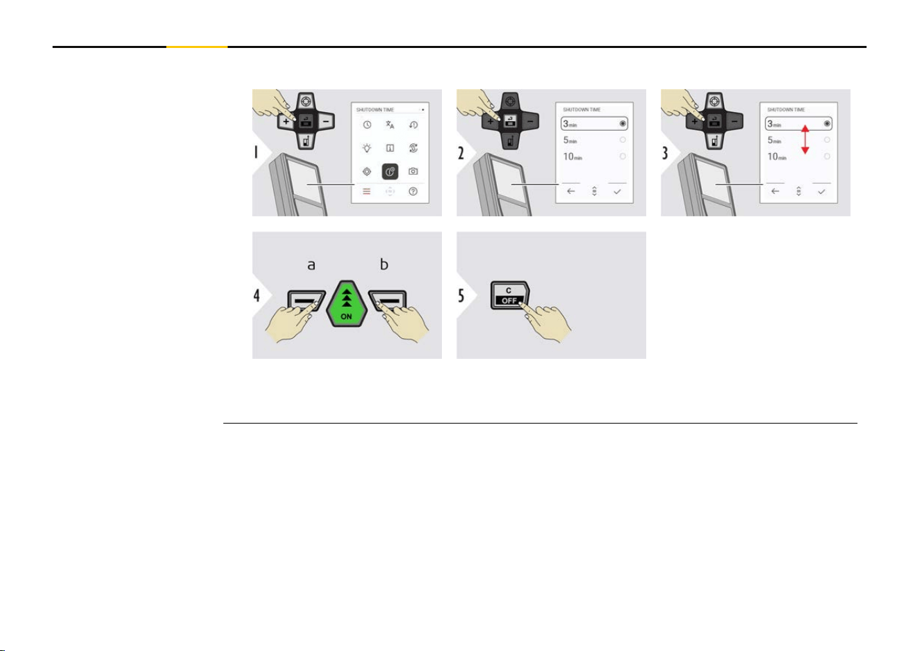
Dene time when device shall switch off automatically.
a Refuse
b Conrm
Exit settings.
SHUTDOWN TIME
54 Settings
This feature is a great help for outdoor measuring. The integrated pointnder (view
screen) shows the target on the display. The device measures in the middle of the
crosshair, even if the laser dot is not visible.
☞
Parallax errors occur when the pointnder camera is used on close targets, with
the effect that the laser appears displaced in the crosshair. In this case, the
error is automatically corrected with a shift of the crosshair.
Option 1:
The status is saved and remains the same, even device is
switched off and on again.
a Press the "Zoom" key to switch the pointnder on.
b
Press and hold the "Zoom" key for 2 s to switch
the pointnder off.
☞
The pointnder can only be switched on/off
once the laser beam is on.
Option 2:
Toggle ON/OFF
Exit settings.
POINTFINDER
55 Settings
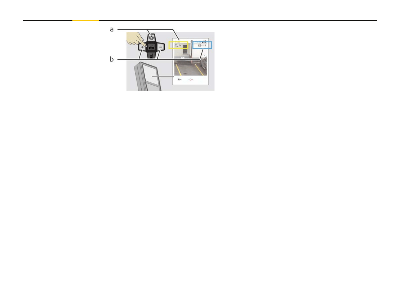
a Adjust zoom while toggling the "Zoom"
key. The zoom stage is shown.
b
Adjust illumination with "Navigate left" and
"Navigate right" keys. The DISPLAY ILLU-
MINATION value is shown.
56 Settings

Close/exit all functions described in this chapter as follows:
Leave menu. Exit.
Displays inclinations of
360°. Instrument beeps at
0°. Ideal for horizontal or
vertical adjustments.
LEVELLING
58 Functions
Aim laser at target. Up to 360° and a trans-
verse tilt of ±10°.
a Measured distance, x
b
Angle, α
c Height difference from measuring point, y
d Horizontal distance, z
Heights of buildings or trees without suitable reective points can be determined. At the
bottom point, distance and tilt are measured - which needs a reective laser target. The
upper point can be targeted with the pointnder/crosshair and does not need a reective
laser target as only the inclination is measured.
SMART HORIZONTAL
HEIGHT TRACKING
59 Functions
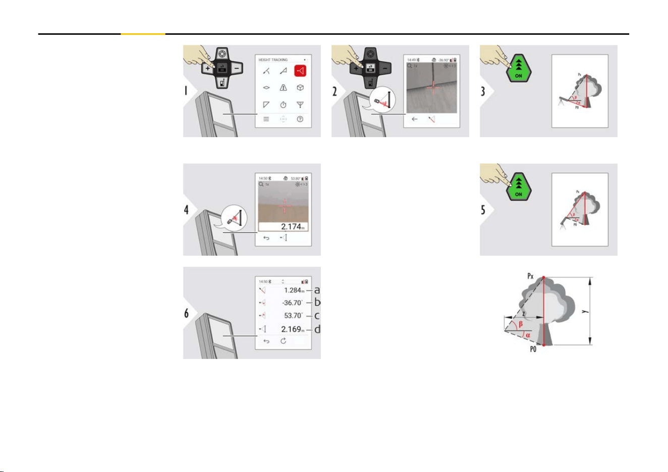
Aim laser at lower point.
Aim laser at upper points
and angle/height tracking
starts automatically.
a Distance P0
b
Angle α
c Angle β
d Tracking height y if
device is turned on
tripod
60 Functions
a Distance z
☞
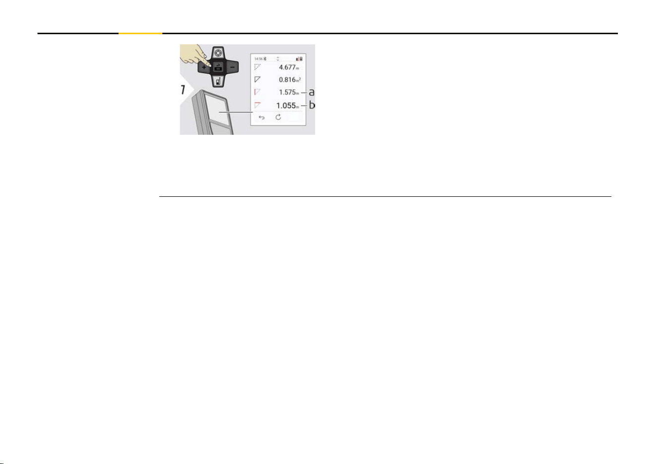
Use the "Navigate downwards" key to take over values in the main line for
sending by Bluetooth.
Aim laser at rst target
point.
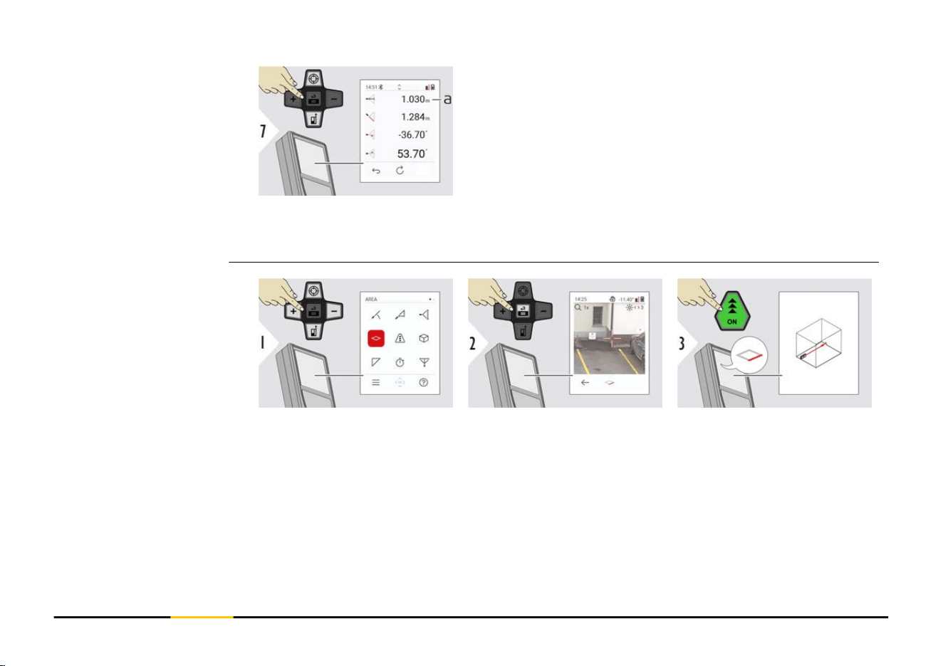
AREA
61 Functions
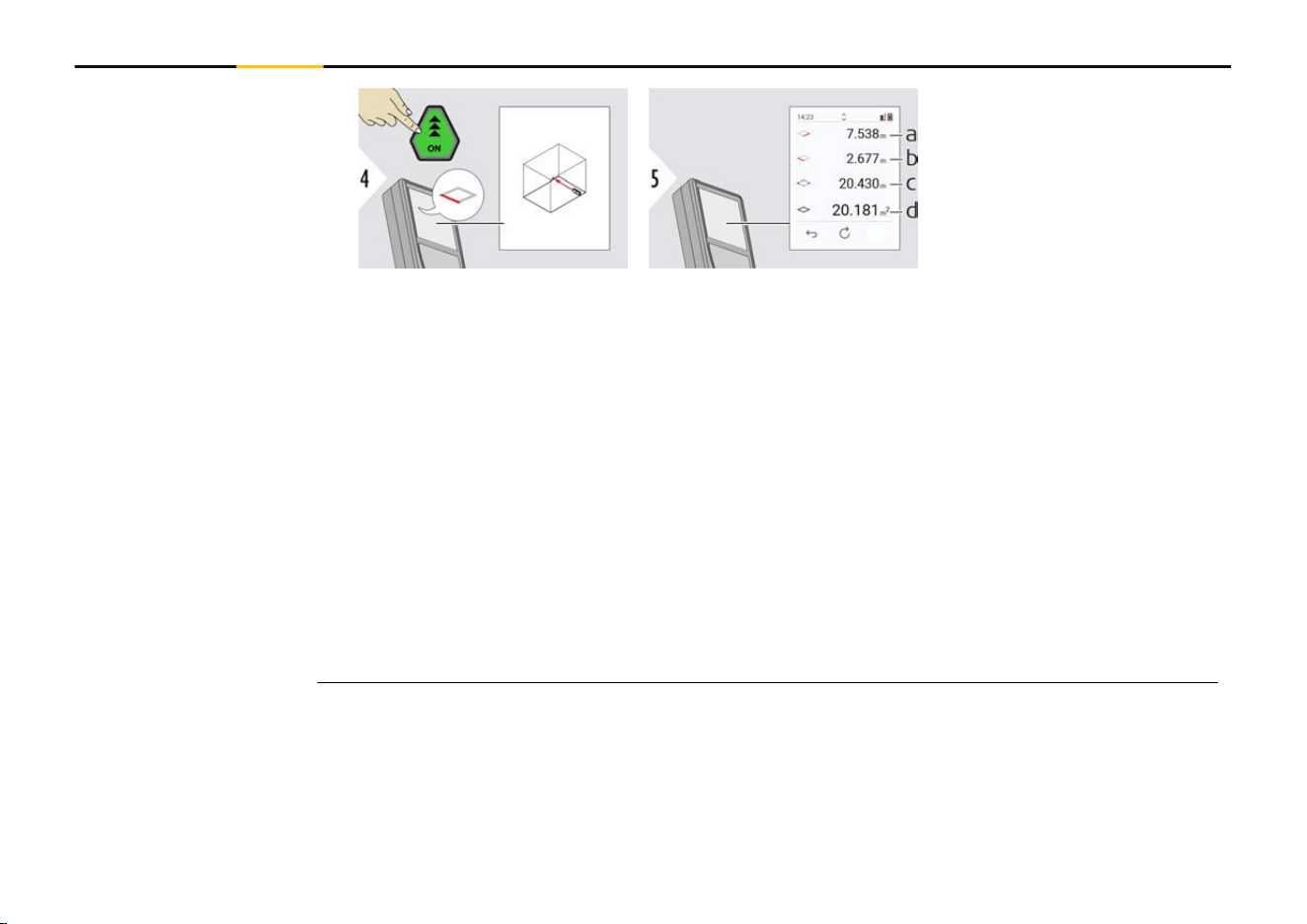
Aim laser at second target
point.
a First distance
b Second distance
c Circumference
d Area
☞
The main result is the area of this rectangle. The individual measured values are
shown above the main line.
Partial measurements/painter function, pointnder OFF:
•
Press "+" before starting the rst measurement
•
Measure all distances, nish with "="
•
Finally, measure the height for the second length to get the wall area
• Press "−" to subtract wall areas (windows, doors), nish with "="
Partial measurements/painter function, pointnder ON:
•
Press "+" for 2 s before starting the rst measurement
•
Measure all distances, press "=" for 2 s to nish
•
Finally, measure the height for the second length to get the wall area
• Press "−" to subtract wall areas (windows, doors), nish with "="
62 Functions
Aim active laser at target.
a Measured distance
Aim laser at rst target
point.
Single DISTANCE
VOLUME
63 Functions
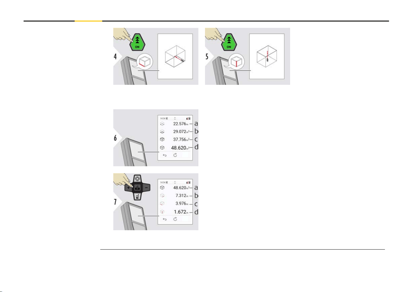
Aim laser at second target
point.
Aim laser at third target
point.
a Circumference
b Ceiling/oor area
c
Wall areas
d Volume
More results.
a Volume
b
First distance
c Second distance
d Third distance
64 Functions
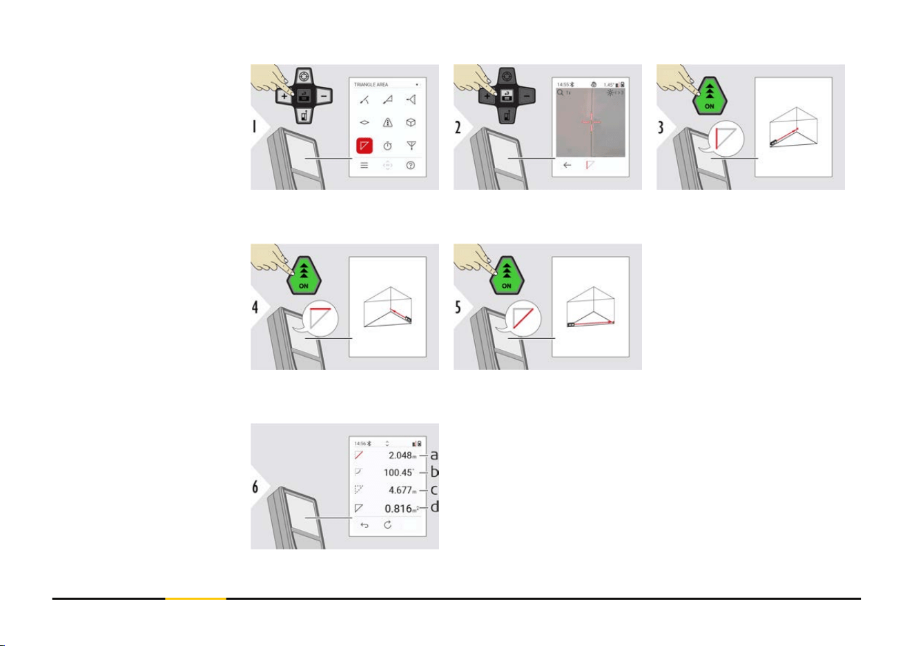
Aim laser at rst target
point.
Aim laser at second target
point.
Aim laser at third target
point.
a Third distance
b Angle between rst and second measurement
c Circumference
d Triangular area
TRIANGLE AREA
65 Functions
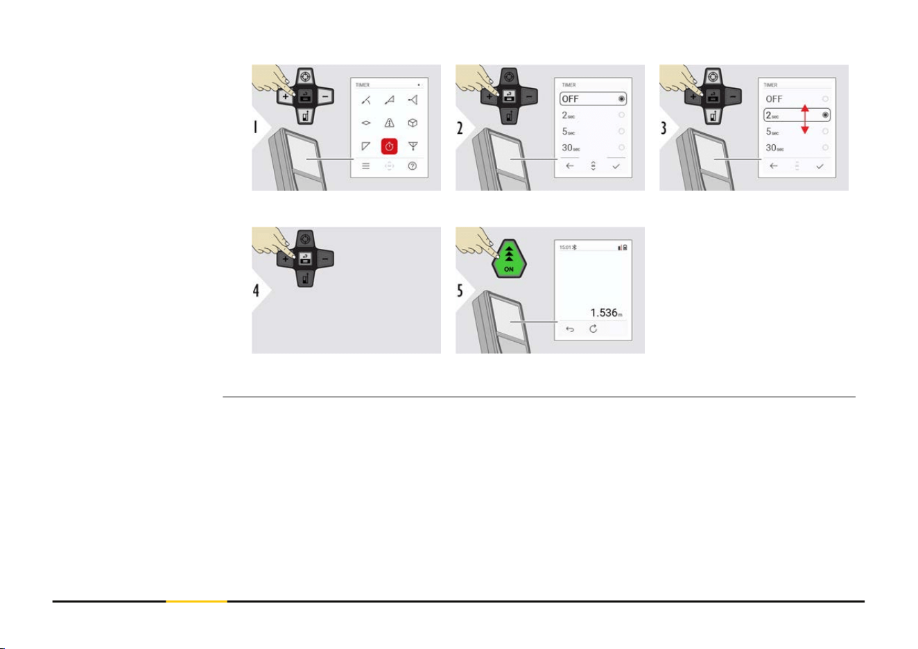
Select release time.
Conrm setting.
The timer starts once the
"ON" key is pressed.
•
The countdown is dis-
played on the screen
•
An interval beep
sounds during the
countdown
TIMER
67 Functions
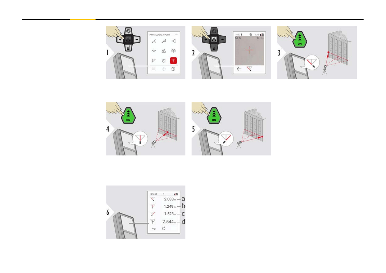
Aim laser at rst target-
point.
Aim laser in a rectangle
against the second target-
point.
Aim laser at third target-
point.
a First distance
b
Second distance
c Third distance
d Distance between rst and third targetpoint
PYTHAGORAS 3-POINT
68 Functions
The result is shown in the main line. Pressing the "ON"
key for 2 seconds in the function activates automatically
minimum/maximum measurement.
We recommend using the Pythagoras only for indirect
horizontal measuring. For height measuring (vertical), it
is more precise to use a function with inclination meas-
urement.
☞
Use the "Navigate downwards" key to take
over values in the main line for sending by
Bluetooth.
a Start measuring.
First measurement
is the reference
point
b Set absolute height
of reference point.
Example: Height
above sea level
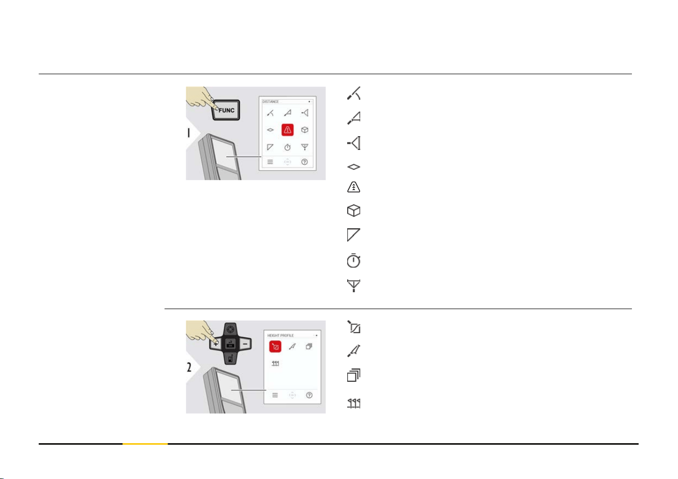
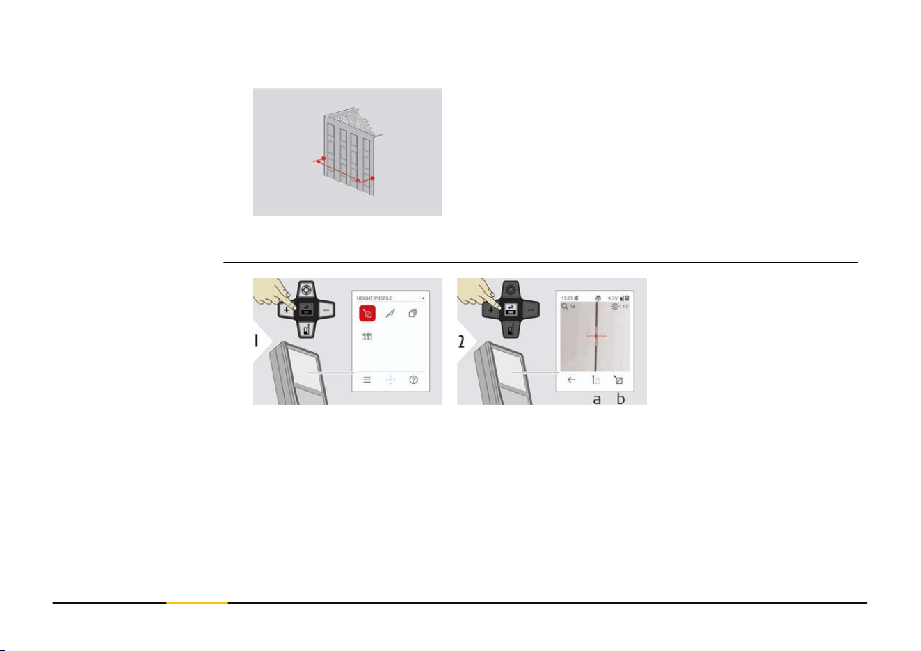
HEIGHT PROFILE
69 Functions
Aim at reference point
(REF).
a Step back to read
out previous meas-
uring points
b
Horizontal distance
to device = d
c Height difference
to reference point
(REF) = h
d Start new height
prole measurement
Exit function.
☞
Press the "ON" key for > 2 s for continuous height prole measuring.
☞
Ideal for measuring of height differences to a reference point. Can be also used
to measure proles and terrain sections. After measuring the reference point,
the horizontal distance and height is displayed for each following point.
70 Functions
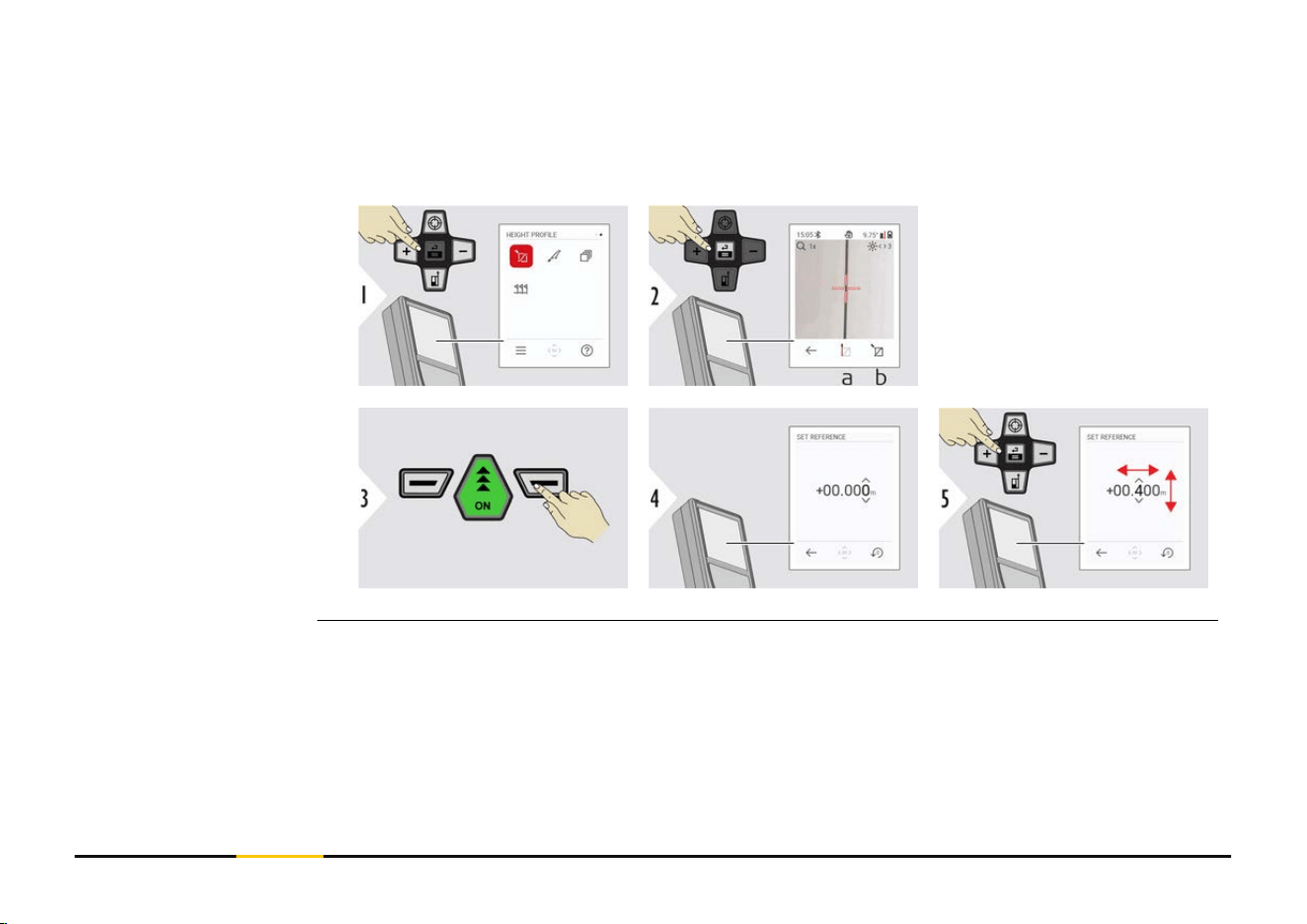
Option: Set absolute height of reference point
It is possible to set the height for the measured reference point. For example: Set level
of the measured reference point to 400 m above sea level. A measured point 2 m above
the reference point would be 402 m then.
a Start measuring.
First measurement
is the reference
point
b
Set absolute height
of reference point
71 Functions
Aim laser at upper target
point.
Aim laser at lower target
point.
a Horizontal distance
between both points
b
Vertical height
between both points
c Included angle
between both points
d Distance between
both points
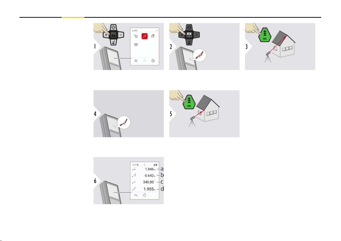
SLOPE
72 Functions
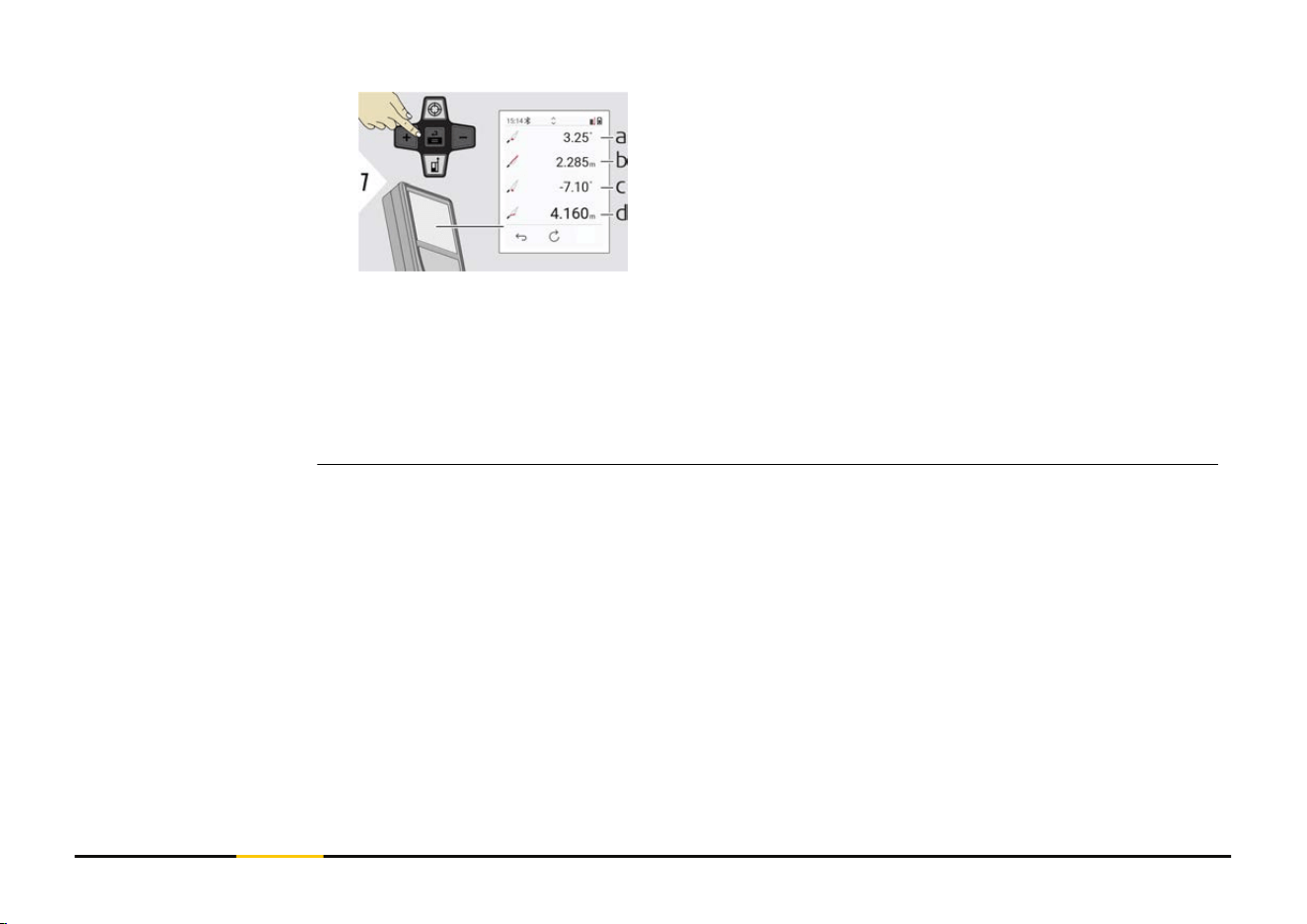
a P1 angle
b
P1 distance
c P2 angle
d P2 distance
☞
Indirect distance measuring between two points with additional results. Ideal
for applications such as length and slope of roof, height of chimneys,…
It is important, that the instrument is positioned in the same vertical plane as
the two measured points. The plane is dened of the line between the two
points. This means, that the device on the tripod is only moved vertically and
not turned horizontally to reach both points.
73 Functions
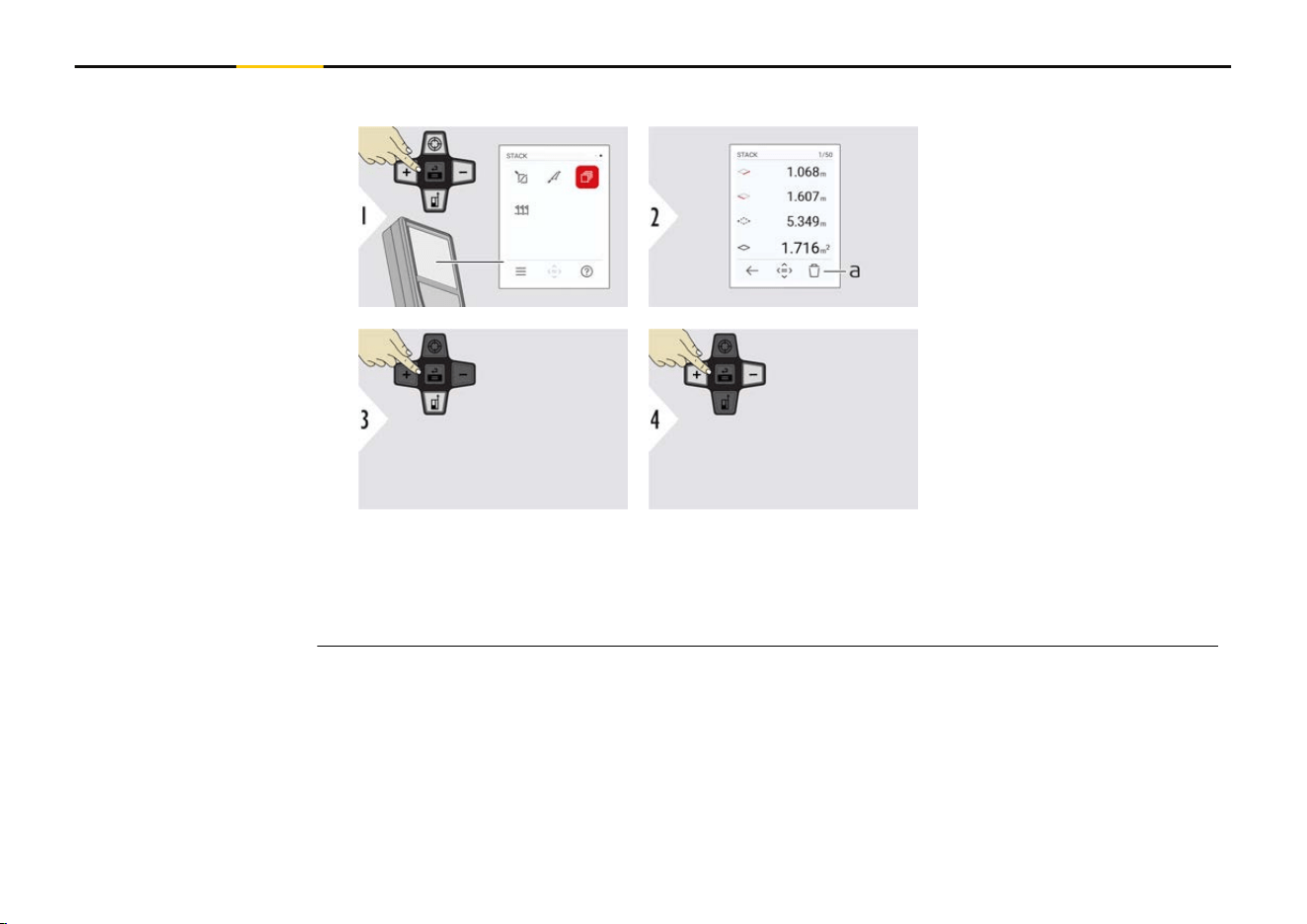
Memory - show last 50 results
a Delete memory
Use "Navigate downwards"
key to show more detailed
results of the specic
measurement.
Use "Navigate left/right"
keys to switch between
measurements.
STACK
74 Functions
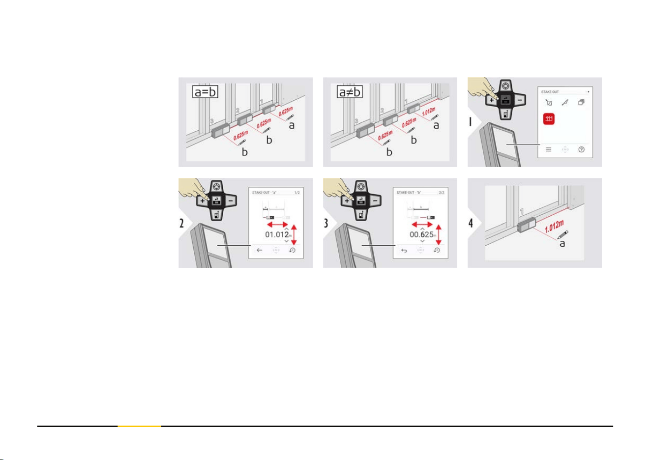
Two different distances, STAKE-OUT - "a" and STAKE-OUT - "b", can be entered to
mark off dened measured lengths.
Adjust distance a.
Press "=" to approve
STAKE-OUT - "a".
Adjust distance b.
Press "=" to approve
STAKE-OUT - "b".
Start measuring. Move
device slowly along the
stake out line. The distance
to the previous/next stake
out point is displayed.
STAKE OUT
75 Functions
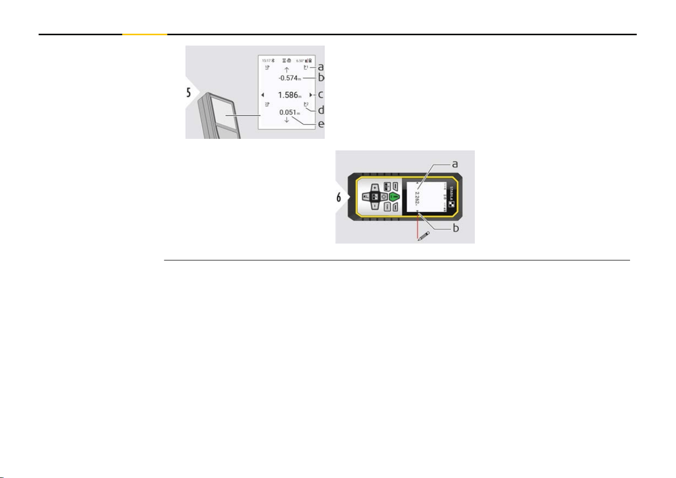
a # of previous stake out
b
Distance to previous stake out
c Total distance
d # of next stake out
e Distance to next stake out
When approaching a stake
out point to less than
18 mm the value of the
stake out point is frozen
and arrows appear on the
side of the display for
marking purposes.
a Value of the current
stake out point
b
Stake out point pos-
ition indicated with
arrows
76 Functions
7 Message Codes
Code Cause Correction
156 Transverse tilt greater than 10° Hold the instrument without any
transverse tilt.
162 Calibration error Make sure the device is placed on
an absolutely horizontal and at sur-
face. Repeat the calibration proced-
ure. If the error still occurs contact
your dealer.
204 Calculation error Perform measurement again.
240-245 Data transfer error Connect device and repeat proced-
ure.
252 Temperature too high Allow device cool down.
253 Temperature too low Warm device up.
254 Battery error Charge batteries.
255 Received signal too weak, meas-
uring time too long
Change target surface (for example
white paper).
256 Received signal too high Change target surface (for example
white paper).
257 Too much background light Shadow target area.
260 Laser beam interrupted Repeat measurement.
Overview
77 Message Codes

Code Cause Correction
298 Battery status poor Replace battery to avoid severe
damage on the device.
299 Hardware error If this message continuously
appears, the device must be ser-
viced. Ask dealer for help.
78 Message Codes

8 Care
•
Clean the device with a damp, soft cloth
•
Never immerse the device in water
•
Never use aggressive cleaning agents or solvents
79 Care

9 Technical Data
Accuracy with favourable conditions
2)
Accuracy with unfavourable conditions
3)
1 mm/0.04″
4)
2 mm/0.08″
5)
Range with favourable conditions
2)
Range with unfavourable conditions
3)
0.05-200 m/0.16-660 ft
4)
0.05-120 m/0.16-400 ft
5)
Smallest unit displayed
0.1 mm/ 1/32″
X-Range Power Technology Yes
Laser class 2
Laser type 635 nm, < 1 mW
Ø laser point | at distances
6/30/60 mm | 10/50/100 m
Tilt measuring tolerance to laser beam
6)
±0.2°
Tilt measuring tolerance to housing
6)
±0.2°
General
2)
Favourable conditions are: white and diffuse reecting target (white painted wall),
low background illumination and moderate temperatures.
3)
Unfavourable conditions are: targets with lower or higher reectivity or high back-
ground illumination or temperatures at the upper or lower end of the specied temper-
ature range.
4)
Tolerances apply from 0.05 m to 10 m with a condence level of 95%. With favour-
able conditions, the tolerance may deteriorate by 0.10 mm/m for distances above 10 m.
5)
Tolerances apply from 0.05 m to 10 m with a condence level of 95%. With unfavour-
able conditions, the tolerance may deteriorate by 0.15 mm/m for distances above 10 m.
80 Technical Data

Tilt measuring range
6)
360°
Protection class IP54 (dust- and splash water protected)
Automatic laser switch off after 90 s
Automatic power switch off Congurable in SHUTDOWN TIME
Bluetooth
Bluetooth power
Bluetooth frequency
Bluetooth range
Bluetooth v5.0
≤ 2.5 mW
2400-2483.5 MHz
10 m
Relative humidity Max. 95% non-condensing
Operation height Max. 3000 m/9840 ft
Battery
Battery durability
3.7 V/2000 mAh
up to 5000 measurements
Dimension (H × D × W) 144 × 60 × 24 mm | 5.67 × 2.2 × 0.94″
Weight (with batteries) 190 g/6.70 oz
Temperature range storage
Temperature range operation
−25 to 70 °C/−13 to 158 °F
−10 to 55 °C/14 to 131 °F
Charging time
Charging temperature
Charging power
3 h
5 to 40 °C
5 V/1 A
6)
After user calibration. Additional angle-related deviation of ±0.01° per degree up to
±45° in each quadrant.
Applies at room temperature. For the whole operating temperature range, the maximum
deviation increases by ±0.1°.
81 Technical Data

Distance measuring yes
Min/Max measuring yes
Permanent measuring yes
Stake out yes
Addition/Subtraction yes
Area yes
Triangle area yes
Volume yes
Painter function (area with partial measurement) yes
Pythagoras 3-point
Smart Horizontal Mode/Indirect height yes
Levelling yes
Memory (STACK) yes
Beep yes
Illuminated colour display yes
Bluetooth yes
Personalised Favourites yes
Timer yes
Height tracking yes
Height prole yes
Sloped objects yes
Functions
82 Technical Data
Hereby, STABILA Messgeräte declares that the radio equipment type
STABILA LD 530 BT is in compliance with Directive 2014/53/EU and other
applicable European Directives.
Hereby, STABILA Messgeräte declares that the radio equipment type STABILA LD 530 BT
is following the provisions of the applicable relevant statutory requirement S.I. 2017
No. 1206 Radio Equipment Regulations 2017.
FCC ID: RFF-LD6BT
FCC Part 15
This equipment has been tested and found to comply with the limits for a Class B digital
instrument, pursuant to part 15 of the FCC rules.
These limits are designed to provide reasonable protection against harmful interference
in a residential installation.
This equipment generates, uses and can radiate radio frequency energy and, if not
installed and used in accordance with the instructions, may cause harmful interference
to radio communications.
However, there is no guarantee that interference will not occur in a particular installa-
tion.
If this equipment does cause harmful interference to radio or television reception, which
can be determined by turning the equipment off and on, the user is encouraged to try to
correct the interference by one or more of the following measures:
EU
UKCA
USA
84 Technical Data

•
Reorient or relocate the receiving antenna
•
Increase the separation between the equipment and the receiver
•
Connect the equipment into an outlet on a circuit different from that to which the
receiver is connected
•
Consult the dealer or an experienced radio/TV technician for help
This device complies with part 15 of the FCC rules. Operation is subjected to the follow-
ing two conditions:
•
This device may not cause harmful interference, and
•
this device must accept any interference received, including interference that may
cause undesired operation.
FCC Radiation Exposure Statement
The radiated rf output power of the instrument is below the FCC radio frequency expos-
ure limits for portable devices according to KDB 447498.
Changes or modications not expressly approved by STABILA for compliance could void
the user's authority to operate the equipment.
CAN ICES-003(B)/NMB-003(B)
IC: 3177A-LD6BT
ISED Statement, applicable in Canada
This device complies with Industry Canada’s licence-exempt RSSs. Operation is subject to
the following two conditions:
Canada
85 Technical Data

1.
This device may not cause interference; and
2.
This device must accept any interference, including interference that may cause
undesired operation of the device.
Radio Frequency (RF) Exposure Compliance Statement
The radiated RF output power of the instrument is below the Health Canada’s Safety
Code 6 exclusion limit for portable devices (radiated element separation distance
between the radiating element and user and/or bystander is below 20 cm).
The conformity for countries with other national regulations has to be approved prior to
use and operation.
Others
86 Technical Data


www.stabila.com
STABILA Messgeräte
Gustav Ullrich GmbH
Landauer Str. 45
76855 Annweiler
Germany
+ 49 63 46 309 - 0