48"
Hydrostatic Walk-Behind
Commercial Rotary Mowers
Standard
Professional Turf Equipment
OPERATOR’S AND SERVICE MANUAL

2
SECTION 1: TABLE OF CONTENTS
FOREWORD.................................................................................................................3
SAFETY PRECAUTIONS .............................................................................................4
SAFETY DECALS FOUND ON YOUR UNIT................................................................5
SPECIFICATIONS.........................................................................................................7
OPERATING INSTRUCTIONS .....................................................................................8
CONTROLS ..................................................................................................................8
INITIAL ADJUSTMENTS...............................................................................................10
BREAK-IN AND OPERATION.......................................................................................11
CUTTING HEIGHT ADJUSTMENT TABLE ..................................................................12
MAINTENANCE ............................................................................................................13
TO CHANGE A BLADE.................................................................................................15
TO CHANGE THE BLADE DRIVE BELTS....................................................................15
TO CHANGE THE PUMP DRIVE BELT:. ......................................................................18
TO CHANGE A SPINDLE ASSEMBLY .........................................................................18
REPLACEMENT PARTS...............................................................................................19
WARRANTY..................................................................................................................20

3
SECTION 2: FOREWORD
The Cub Cadet Commercial Hydro Walk-Behind Commercial Rotary Mower has been
developed for use by professional landscapers, commercial lawn service companies,
professional turf managers and golf course superintendents. The machine incorporates many
safety features that should be studied by all operators and maintenance personnel before use.
The list of safety precautions should receive particular attention. This manual presents the
operating and maintenance instructions necessary to keep your Cub Cadet Commercial
mower at peak efficiency. If properly operated and maintained, your Cub Cadet Commercial
mower will give dependable and trouble-free service. Although hazard control and accident
prevention are partially dependent upon the design and configuration of the equipment, these
factors are also dependent upon the awareness, concern, prudence, and proper training of the
personnel involved in the operation, transport, maintenance and storage of the equipment.
The Cub Cadet Commercial Hydro Walk-Behind Commercial Rotary Mower
should only be operated and maintained by thoroughly trained individuals. The
machine could cause serious injury to anyone who misuses it or does not under-
stand its operation. All operators and maintenance personnel are urged to read
this entire manual for their personal safety.
MODEL LISTED IN THIS MANUAL
17HP 48" Fabricated Deck
55AG5D4V750

4
SECTION 3: SAFETY PRECAUTIONS
A. GENERAL:
1. Read this Operator’s Manual before starting the mower. Study the controls and learn the proper sequence of operation.
2. Do not allow anyone to operate or maintain this machine who has not read the manual.
Never permit children to
operate this machine.
3. Always have your feet and hands clear of the cutter deck when starting the engine.
4. Do not remove any shields, guards, decals or safety devices. If a shield, guard, decal or safety device is damaged or does
not function, repair or replace it before operating the mower.
5. Always wear safety glasses, long pants and safety shoes when operating or maintaining this mower. Do not wear loose-
fitting clothing.
6. Never run the engine indoors without adequate ventilation.
Exhaust fumes are deadly.
7. To avoid serious burns, do not touch the engine or muffler while the engine is running or until it has cooled after it has
been shut off.
8. When looking for oil leaks, never run your hand over hydraulic hoses, lines or fittings. (High-pressure oil can easily
penetrate the skin.) Never tighten or adjust hydraulic hoses or fittings while the system is under pressure.
B. RELATED TO FUEL:
1. Gasoline is highly flammable. Respect it.
2. Do not smoke or permit others to smoke while handling gasoline.
3. Always use approved containers for gasoline.
4. Always shut off the engine and permit it to cool before removing the cap of the fuel tank.
5. If the fuel container spout will not fit
inside
the fuel tank opening, use a funnel.
6. When filling the fuel tank, stop when the gasoline reaches one inch from the top. This space must be left for expansion.
Do not overfill.
7. Wipe up any spilled gasoline.
C. WHEN MOWING:
1. Keep adults, children and pets away from the area to be mowed.
2. Never use this mower without the grasscatcher or discharge chute installed and set in the down position.
3. Mow only in daylight.
4. Always check the area to be mowed and remove debris and other objects prior to mowing.
5. Watch for holes, sprinkler heads and other hidden hazards.
6. Reduce speed when making sharp turns.
7. Always have proper footing on slopes and hillsides and never operate when conditions are slippery. Be very careful on
wet grass.
8. Always keep both hands on the speed/directional control levers.
Always walk, never run.
9. Never engage the blade clutch when the engine is running unless you are on grass that you intend to mow.
10. Be careful when crossing gravel paths or roadways. Always disengage the blade clutch and wait until the blades stop
rotating.
11. Never leave the mower unattended without disengaging the blade clutch, placing the ground speed/directional control
levers in neutral, shutting off the engine, taking the key from the ignition switch and closing the fuel shutoff valve.
12. Always park the mower and start the engine on a level surface with the ground speed/directional control levers in neutral,
and the blade clutch disengaged.
13. Shut off the engine and wait for the blades to stop rotating before removing the grass catcher.

5
14. If you hit a solid object while mowing, disengage the blade clutch, place the ground speed/directional control levers in
neutral, and stop the engine. Disconnect the spark plug wire and inspect for damage. Repair any damage and make sure
the blades are in good condition and the blade bolts are tight before restarting the engine.
15. Do not mow excessively steep (more than 15 degrees) slopes. Mow across the slope, not up and down the slope.
16. Never raise the mower deck while the blades are rotating.
17. Never walk or stand on the discharge side of a mower with the engine running. Disengage the blade clutch if another
person approaches while you are operating a mower.
18. Always disconnect the spark plug wire to prevent the engine from accidentally starting before performing any maintenance
on this mower.
19. Keep the mower and especially the engine/pump area clean and free of grease, grass and leaves to reduce the chance of
fire and to permit proper cooling.
20. The operator presence controls are integrated into each speed/directional control lever. Do not try to defeat their
operation. If the blade clutch is engaged or either of the ground speed control levers are out of the neutral position,
releasing both handles will shut off the mower’s engine.
SECTION 4: SAFETY DECALS FOUND ON YOUR UNIT
Keep safety decals clean. Replace any safety decal that is damaged, destroyed, missing,
painted over or can no longer be read. Replacement safety decals are available through your
dealer.
WARNING
OPEN BELT DRIVE
STOP ENGINE BEFORE
REACHING UNDERNEATH
Do not operate without discharge deflector
or entire grass collection system in place.
Do not remove grass catcher until blades
have stopped.
WARNING
SHIELD MISSING
DO NOT OPERATE
WARNING

6
SAFETY DECALS FOUND ON YOUR UNIT
- TURN OFF ENGINE AND ALLOW
TO COOL BEFORE REFUELING.
- DO NOT SMOKE NEAR FUEL.
WARNING
CLOSE FUEL VALVE
WHEN MACHINE IS
NOT IN USE
IF VALVE IS LEFT OPEN,
SEVERE ENGINE DAMAGE
OR HARD STARTING MAY
RESULT FROM FLOODING

7
SECTION 5: SPECIFICATIONS
POWER UNIT:
MODEL 1748FF
Engine MFG
Kawasaki
Horsepower
17HP
Type
4 Cycle Twin
Starter
Electric
Air Cleaner
--------------- Dual Element, Dry ----------------
Lubrication
--------------- Pressure with Filter ---------------
Fuel Tank
5 gallon
Traction Drive
Two variable displacement pumps and two
wheel motors
Filtration
--------------------- Internal ---------------------
Ground Speed
0-6 mph
Drive Wheels
18 x 8.50-8
Control
Right and left traction/steering levers; right and
left ground speed control levers, Electric blade
clutch; engine throttle; ground speed/directional
control and operator presence safety group;
key-type ignition switch; hour meter.
Frame
7 gauge Steel plate. All welded construction.
Handles
Steel tubing. All welded construction.
Mower Type
Float/Fix-Adjustable
Cutting Width
48"
Overall Width
58" (chute down)
Number of Blades
3
Cut Height
1-1/2"-4"
Deck Material
7 gauge steel
Caster Wheels
-------------------- 9 x 3.50-4 ----------------------
Puncture proof tires. Wheels have open-cage
roller bearings.

8
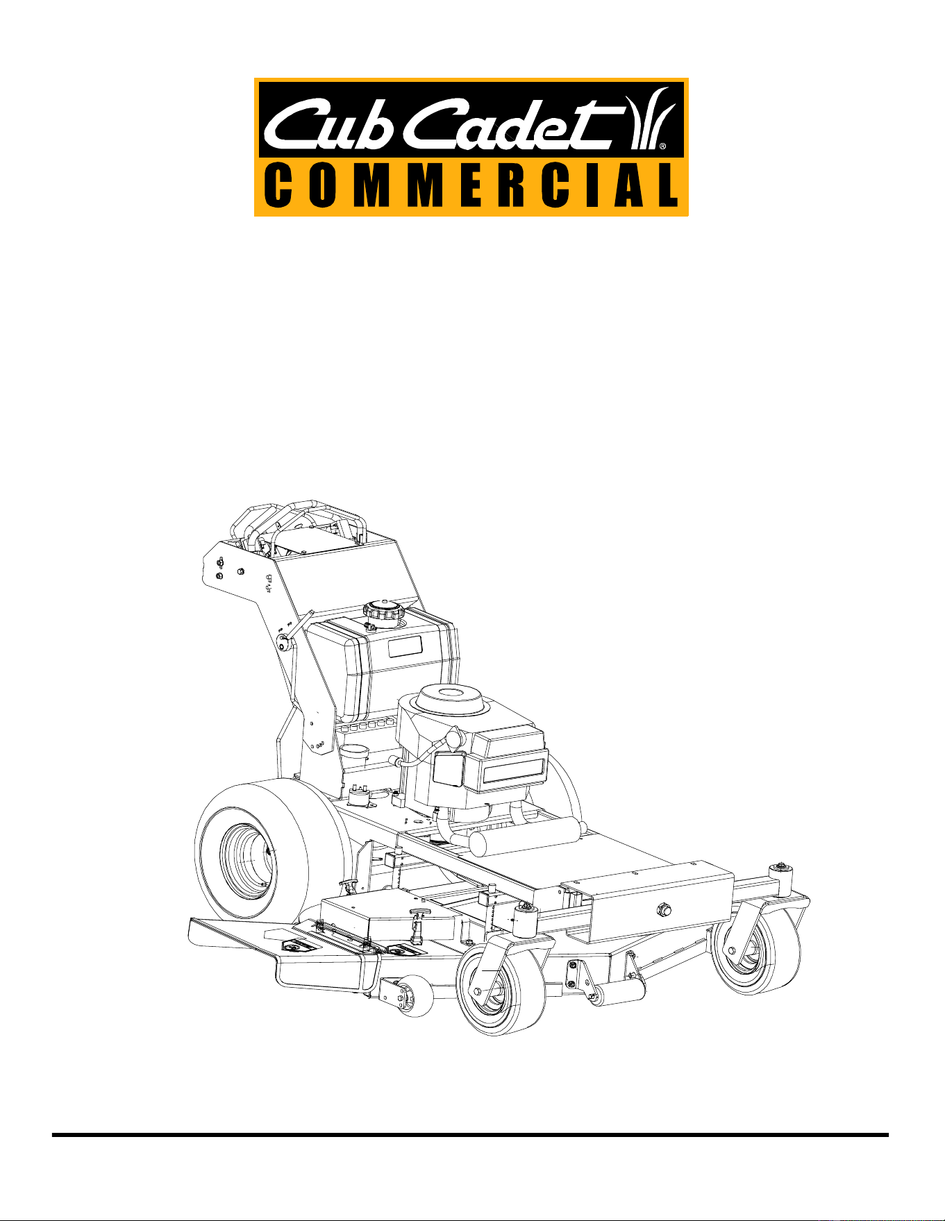
SECTION 6: OPERATING INSTRUCTIONS
Figure 1
A. CONTROLS
1. Ignition Switch:
Located on the right side of the control panel between the handles. When the blade clutch
is disengaged the engine can be started by turning the key in the clockwise position. The engine can be shut
off by turning the ignition key 45° counterclockwise.
2.
Fuel Shutoff Valve:
Located on top of the fuel tank. The handle turns 90 degrees. When the handle is in a
horizontal position, it will shut off the flow of fuel to the engine. When it is turned to a vertical position, it will
open and allow fuel to flow to the engine. Anytime the mower is being trailered or, if the mower will not be in
use for 30 minutes or more, close the fuel shutoff valve to prevent flooding the engine.
3. Engine Throttle:
Located on the left side of the control panel. Moving the throttle lever from the bottom to the
top will increase the engine speed from slow to fast. To start the engine, set the throttle all the way to the top
position. After the engine starts, move the throttle halfway between slow and fast. Always mow at full throttle.
4. Choke:
Located on the left side of the control panel, pull the choke out while starting the engine. After the
engine starts, push the choke in.
5. Traction/Steering Levers:
There is a right-hand lever and a left-hand lever located on top of the handle
assembly. Each lever operates independently to control the ground speed. When both traction/steering levers
are released, the mower will automatically return to neutral position. Steering is accomplished by pushing on
the traction/steering lever on the opposite side to which the turn is to be made. Reverse is accomplished by
pulling both handles back at the same time.
6. Electric Blade Clutch:
Figure 1 shows the electric blade clutch located on the center of the control panel.
This is an on/off toggle switch that controls the electric blade clutch which supplies power to the cutting
blades.
7. Operator Presence Levers:
Located within the right and left handles, these levers must be held down
against spring pressure when the engine is running and the electric clutch is engaged. Releasing the operator
presence levers with the blade clutch engaged will shut off the engine.
8. Cruise Handle Locking Lever:
Located on the left side of the handle assembly. This lever will allow you to
Lock the Cruise Handle or Unlock the Handle.
Cruise Handle
Locking Lever
Engine
Throttle
Right Traction
Steering Lever
Lever
Operator Presence
Electric Blade
Clutch
Ignition
Switch
Choke
Hour Meter
Left Traction
Steering Lever
9
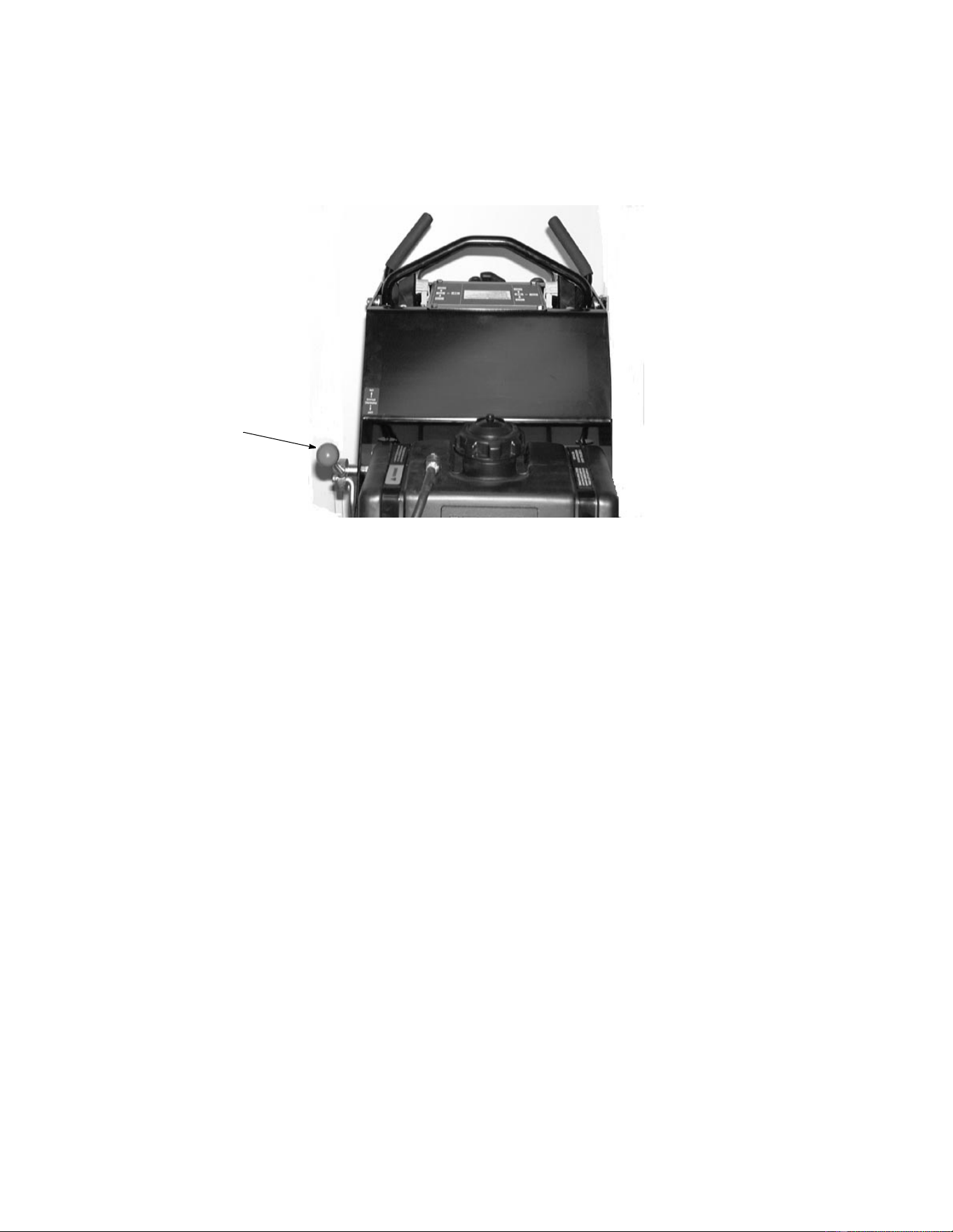
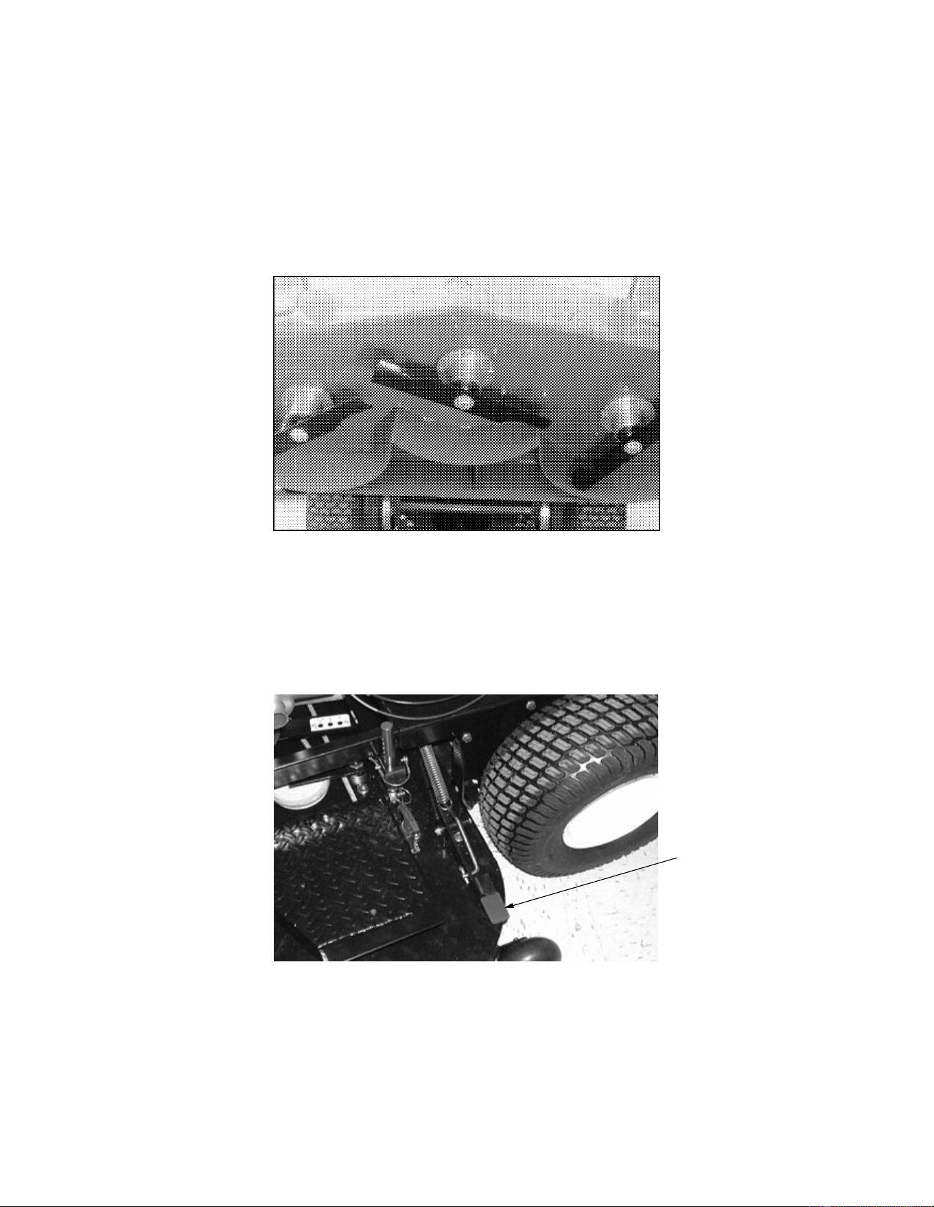
9. Freewheeling Valves:
When it is neccessary to push or pull the mower, there are two rods located on the
rear of the machine which need to be pulled out. This action will permit the unit to by-pass internal hydraulic
pressure and allow the unit to be moved. Remember to push the rods in before attempting to drive the unit.
10. Parking Brake Lever:
If you are in the operator position it is located on the right side of the unit, and if you
are facing the unit and not in the operator position it is located on the left side of the unit. This lever allows you
to engage the parking brake.
11. Hour Meter:
Located at the lower right edge of the control panel. The meter records total operating hours
and operates only when the engine is running. This hourmeter indicates hours when the engine is not running
and engine rpms when the engine is running. This unit also indicates lubrication intervals by flashing “LUBE”,
and it also indicates engine oil and filter change intervals by flashing “oil”. Both service reminders will flash
whether or not the engine is running.
Parking
Brake Lever

10
B. INITIAL ADJUSTMENTS
1. Disconnect the spark plug wire.
2. Check the tire pressure. Drive Wheels should be inflated to 12-15 psi. Caster Wheels are semi-pneumatic and
do not require inflation. Note: New tires are overinflated in order to properly seat the bead to the rim.
3. Check that all nuts, bolts and screws are tight.
4. Check the tension of the deck drive belts:
a. Remove the deck cover.
b. The tension of the deck drive belts are maintained by a spring mechanism that adjusts for wear and
stretch.
c. Examine the belts for cuts, fraying and excessive wear. Replace if any of these are detected.
d. Replace the deck cover.
5. The tension of the pump drive belt should be adjusted so that a five-pound pull between the engine traction
drive pulley and the pump drive pulley opposite the idler pulley deflects the belt about 3/16".
6. The long traction/steering control rods which connect to the lower bellcrank on each side of the handle
assembly should initially be adjusted so that when the ground speed/directional control levers are in neutral,
the mower stands still with the engine running.
If the mower starts to creep forward or to the rear in this situation, the control rod on the side of the mower
which seemed to creep must be adjusted.
Pull the hair pin at the top of the rod and loosen the nut at the bottom. Adjust until the drive wheel stops
moving. Then retighten the bottom nut and replace the hair pin.
7.
Adjusting the cutting height:
To change the cutting height, remove the four pins which go through the four
rods located at each corner of the mower deck. Lift one side of the deck, using provided handle, to desired
height and replace pin.
8. Lubricate all fittings listed in the maintenance section.

11
C. BREAK-IN AND OPERATION
1. Make certain you thoroughly understand all of the safety precautions before you attempt to operate
this machine.
2. Check the engine oil level. Fill to the proper level with 10W-30 engine oil rated for service SE or SF.
3. Check the hydraulic oil level. Make sure the hydraulic oil level is up to the bottom of the oil level line on the
tanks. If the hydraulic oil level is low, fill with Mobile DTE 26 oil.
4. Move the mower outdoors. Check the engine gasoline level. When filling the tank, stop when the gasoline
reaches one inch from the top. This space must be left for expansion. Use fresh, clean, unleaded, regular
gasoline.
5. Move the mower to a “test area” where you can operate the mower for about half an hour without being
disturbed.
6. To start the engine:
a. Disengage the blade clutch.
b. Connect the spark plug wires.
c. Open the fuel shutoff valve.
d. Pull the choke to the out position.
e. Turn the key to the full clockwise position until engine starts.
f. When the engine starts, slowly open the choke all the way. Set the throttle at 50% of full engine
RPM and allow the engine to warm up. Then, adjust the throttle to 75% of full engine RPM.
7. After the engine has warmed up, shut off the ignition switch and check the operation of the safety switches.
Make certain that the engine will not start with the blade clutch engaged. If the engine will start with the blade
clutch engaged, immediately shut off the engine and adjust or replace, if necessary, the blade safety switch
mounted in each handle lever with levers into neutral, restart the engine, hold the left operator presence
control down against the left handle and engage the blade clutch. Now take your hand off of the operator
presence lever and the engine should die. If it does not, immediately shut off the engine and adjust or replace,
if necessary, the operator presence switch under the handle levers. Disengage the blade clutch.
8. Restart the engine. Pull PTO switch until it engages and the cutter blades start rotating.
9. Move the ground speed control bar forward to about
one third of full speed.
10.Slowly push the traction/steering levers and the mower will move ahead in a straight line. To turn the mower,
push the traction/steering lever on the opposite side to which you want to turn.
11.To stop the mower’s forward motion, simply release the handle levers and they will return to neutral.
12.Before moving into reverse, the mower’s forward motion should be completely stopped.
13.To stop and shut off the mower, release both traction/steering levers, disengage the blade clutch, turn off the
ignition to stop the engine, close the fuel shutoff valve and disconnect the spark plug wires.
14.Check, and adjust if necessary, the tension of the deck drive belts and the pump drive belt as described in
items 4 and 5 of the Initial Adjustment section.
15.Readjust the traction/steering control rods. These adjustments are described in item 6 of the Initial Adjustment
section.
16. After the first full day of mowing, all nuts, bolts and screws should be rechecked for proper tightness and the
belts should be rechecked for proper tension.
12
SECTION 7: CUTTING HEIGHT ADJUSTMENT TABLE
Note: The front edge of the cutting deck should be 1/8”-1/4” below the rear edge of the deck so that the blades are
cutting grass in only the front half of their circular path. This decreases friction and reduces the drive power
required.
Note: In order to achieve the proper hole location, the number of holes listed
in the chart above are from the top down.
Approximate
Cutting
Height Float Fix
Inches Hole in Pin
(see note below)
Hole in Tube Hole in Pin
(see note below)
1-3/4 Top 5
24Bottom7
2-1/4 Top 6
2-1/2 5 Bottom 8
2-3/4 Top 7
36Bottom9
3-1/4 Top 8
3-1/2 7
3-3/4 Top 9
48
4-1/4
4-1/2 9
Shown in Float Position
Shown in Fixed Position (Top Hole)

13
SECTION 8: MAINTENANCE
WARNING:
Disconnect the spark plug wires to prevent the engine from accidentally starting
before performing any maintenance on this mower.
A. GENERAL MAINTENANCE:
1. If the mower must be tipped on its side for maintenance, first drain the fuel from the fuel tank, the oil from the
engine’s crankcase and the hydraulic oil from the supply tank.
2. Be careful not to spill oil on any of the belts.
3. Do not tamper with the engine’s governor settings. They are adjusted to provide the proper maximum engine
speed.
4. If the mower is to be in storage for more than 30 days, drain the fuel tank, run the engine to drain the
carburetor dry, change the oil, remove the spark plug and pour a teaspoonful of oil into the cylinder. Run the
starter briefly to crank the engine and distribute the oil then replace the spark plug.
B. DAILY MAINTENANCE AFTER MOWING:
1. Park the mower outside the storage facility with the engine shut off.
2. Close the fuel shutoff valve.
3. Permit the mower to cool.
4. Disconnect the spark plug wire.
5. Wash the mower off with water. Be sure to clean out grass clippings from under the cutter deck and also
under the deck cover. Allow the mower to dry before storing.
6. Check that the blade mounting bolts are tight.
7. Check that the blades are sharp. NOTE: Never mow with dull blades.
8. Check the fuel level, the engine oil level and clean the cooling-air intake (the rotating screen).
9. Clean the air cleaner elements (foam and paper).
10.After the first 5 hours of use, change the engine oil. (Change the oil every 100 hours thereafter.)
11.Follow the lubrication chart on the following page.
12. Place the mower in locked storage to avoid tampering or use by an untrained operator.
13. Check condition and operation of all safety switches.
C. MAINTENANCE EVERY 100 HOURS:
1. Change the engine oil and replace the oil filter. (Change the engine oil more frequently under severe
operating conditions.)
2. Check that all nuts, bolts and screws are tight.
3. Check the condition and tension of all belts.
4. Clean the spark plug and check the spark plug gap.
5. Follow the lubrication chart on the following page.
14
D. LUBRICATION CHART:
Figure 2
E. ENGINE MAINTENANCE:
For detailed maintenance instructions for the engine on your mower, see the Engine Manual packed with your
mower.
NUMBER OF
GREASING
POSITIONS ITEM DESCRIPTION
DAILY
3 A Cutter Blade Spindle Bearings
EVERY
40
HOURS
2
2
1
1
2
B
C
D
E
F
Caster Wheel Bearing
Caster Wheel Pivot Shafts
Pto Idler Pulley
Deck Idler Pulley
Ball Wheels
Hydro Deck Mowe
r
A
C
F
B
A
A
C
F
B
E
D
15
F. MOWER MAINTENANCE
1. TO CHANGE A BLADE:
a. Remove the deck cover.
b. Tip the mower back and block up the front of the deck.
See Figure 3.
c. Place one wrench on the hex head bolt under the blade. Use a second wrench to remove the nut
on top of the spindle pulley.
d. Remove the (3/4" x 7") blade bolt, the flat washer, the blade and the blade spacer. (
Note: torque the
3/4" bolt 90-115 ft.lbs.
)
Figure 3 48" Cutting Deck Shown
e. To replace the blade, reverse the above procedure. Be careful to replace the blade spacers
correctly above and below the spindle.
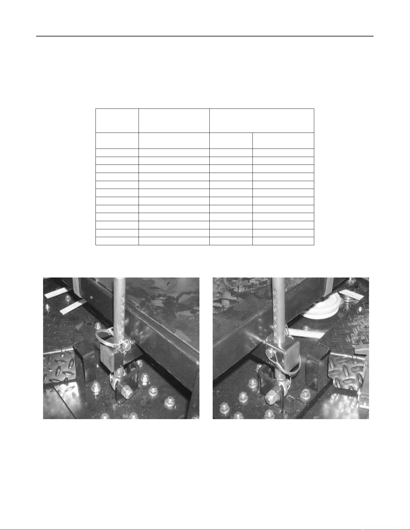
2. TO CHANGE THE BLADE DRIVE BELTS:
a. Remove the deck cover.
b. Release over-center tensioner mechanism. See Figure 4.
Figure 4
c. Slip PTO from pulleys.
d. Use 3/8” drive ratchet and release tension on mower deck belt to remove belt.
e. Place a new blade drive belt through the belt on the deck pulleys.
f. Replace PTO belt.
g. Replace the deck cover.
K

16
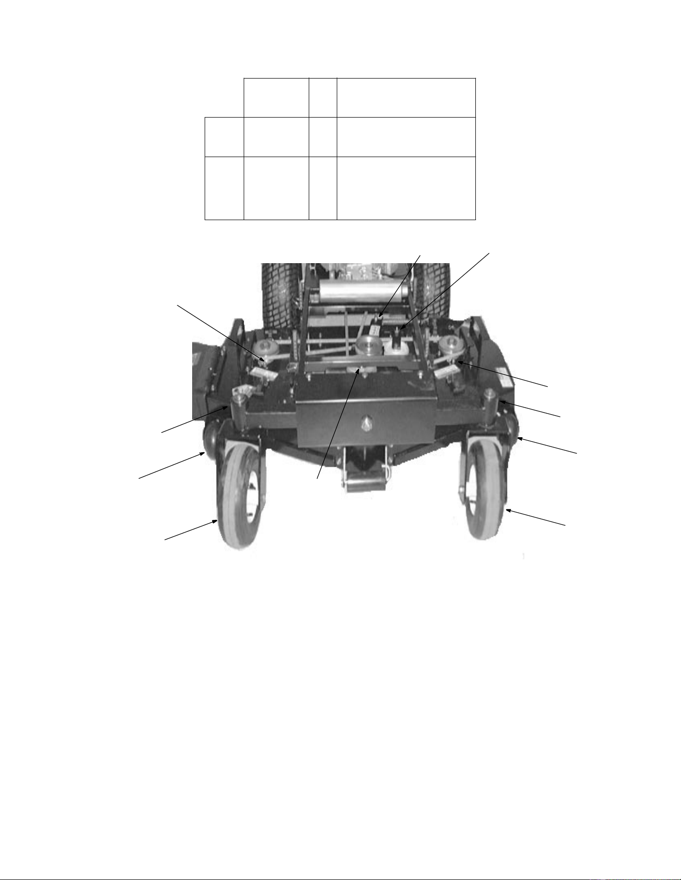
3. INSTALLATION AND REMOVAL OF MOWER DECK:
Place the mower deck in front of the power unit on a level surface. Turn off power take-off (PTO), turn off engine
and remove key from ignition switch.
CAUTION:
The mower deck and power unit must be placed on a hard, level surface.
WARNING:
Disengage the PTO, stop engine and remove key to avoid accidental starting and
injury.
WARNING:
When handling the mower deck, be careful not to cut yourself on the sharp blades.
1. Pull out release rods located on rear of unit to move unit without engine running.
2. Remove center mower deck cover.
3. With the mower deck positioned in front of the power unit,
visually align
mower deck channels with power unit
frame tubes.
4.
Push down on power unit handle bar to bring the front caster wheels to a level above top of the mower deck.
5.
Push the power unit over the mower deck.
6. Slowly reduce force on the handle bar to lower the front caster wheels until they rest on the surface with the
frame tubes inside the mower deck channels.
7. Push the power unit forward until pins on deck align with rod end holes.
INSTALLING THE MOWER DECK
WARNING:
Disengage PTO, stop engine and remove key to avoid accidental starting and
injury.
WARNING:
When handling the mower deck, be careful not to cut yourself on the sharp blades.
1.
Slide rod ends over pins on deck and install “klick pins”. Note: Rods with rod ends may be pre-installed onto
deck.
2. Lift one side of mower deck to desired height and place pin in hole.
NOTE:
The same height adjustment holes must be used for both front and rear (left and right side) pin
installations.
3.
Release the mower deck.
4. Repeat the above procedure to install the other side of the mower deck.
NOTE:
The same height adjustment holes must be used for all four pin installations.
5.
Adjust the mower deck as required. Refer to “Adjustments” in your Operator’s Manual.
6. Install the PTO belt by executing the following procedures:
1. Remove center mower deck cover.
2. Release over center tensioner by lifting upward.
NOTE:
Be sure the narrow side of the belt is in the bottom of the pulley grooves.
3. Replace belt.
4. Release force on the idler arm to restore tension to new PTO belt.
5. Replace center mower deck cover and secure.
7. Return release rods to normal operating position.

17
REMOVING THE MOWER DECK
WARNING:
Disengage PTO, stop engine and remove key to avoid accidental starting and
injury.
WARNING:
When handling the mower deck cover, be careful not to cut yourself on the sharp
blades.
1. Remove the center mower deck cover.
2. Remove the PTO belt.
3. Lower the deck to the ground by removing large pins at the top of each post. Remove small round “klick” pins
located on top of the deck.
4. Pull release rods out on rear of unit.
5. Pull unit backward and push down on the power unit handle bar to bring the front caster wheels to a level
above the top of the mower deck.
6. Pull the power unit backwards, free of the mower deck. Slowly reduce force on the handle bar to lower the
front caster wheels until they rest on the surface.

18
4.
TO CHANGE THE PUMP DRIVE BELT:
See Figure 5.
a. Make sure the blade clutch is disengaged.
Figure 5
b. Working under the engine deck, take the long blade drive belt off of the engine pulley.
c. Use 3/8” drive ratchet to release tension on drive belt.
d. Remove the old belt and mount a new belt on the pulleys, while releasing tension on idler.
e. Replace the long blade drive belt on the engine pulley.
5. TO CHANGE A SPINDLE ASSEMBLY
a. Make sure the blade clutch is disengaged.
b. Remove the deck cover or covers.
c. Remove the blade.
d. Remove the blade drive belts.
e. Tip the mower back and block up the front of the deck.
f. Remove the bolts and locknuts (four for fixed and three for float decks) holding the spindle
assembly to the deck.
g. Remove the spindle assembly.

19
SECTION 9: REPLACEMENT PARTS
SUGGESTED MOWER REPLACEMENT PARTS
SUGGESTED ENGINE REPLACEMENT PARTS
Part No. Description Qty.
01005336 Rotary Blade, 17.0" 3
01005213 3/4"-16, Hex Cap Screw, 7.0 2
01005388 3/4"-16, Hex Cap Screw, 9.0 1
01000380 3/4"-16, Hex 3
01004415 Spacer .76 ID x 2.00 OD x .900 3
01002564 Spacer .76 ID x 2.00 OD x .477 3
01005374 Spindle Drive Belt 1
01009211 V Belt 1
01008904 Pump Drive Belt 1
Engine Oil Filter Air Filter Air Filter Foam
Wrap
Spark Plug
01009355 Kawasaki, 17 HP KM-49065-2078 KM-11013-7002 KM-11013-7001 759-3331

Form No. 01009495 Rev. 03-0 11/18/2003
MANUFACTURER’S LIMITED WARRANTY - TURF EQUIPMENT
This warranty is specific to the product manual to which it is attached.
For a complete list of products and warranties contact your authorized Cub Cadet Commercial dealer.
Proper maintenance of the purchased Cub Cadet Commercial equipment is the owner’s responsibility.
Follow the
instructions in your owner’s manual for correct lubricants and maintenance schedule. Your Cub Cadet Commercial dealer
carries a complete line of quality lubricants and filters for your equipment’s engine, transmission, chassis, and attach-
ments.
What is Covered By This Warranty?
This limited warranty covers any defect in materials and/or workmanship in your
Cub Cadet Commercial equipment to the original owner for the following time periods:
A) First (1
st
) Year of Original Ownership:
Both
Parts
found defective in materials and /or workmanship
and
the
associated
Labor
of the particular repair are covered under the terms of this limited warranty
B) Second (2
nd
) and Third (3
rd
) Year of Original Ownership:
Parts
found defective in materials and /or workmanship are
covered under the terms of this limited warranty.
•
Limited Battery Warranty
: 90-day free battery replacement in the case of defects in materials and/or
workmanship, thereafter prorated for the period from the fourth (4th) through the twelfth (12
th
) month of ownership.
•
“No-Fault Warranty”: Covers the “No-Fault” to owner replacement of damaged belts, tires, seats, and grass
bags (cutting blades are not included) for a period of One (1) month or One-Hundred (100) hours, whichever comes first.
•
Limited Engine Warranty
: Parts and Labor for defects in materials and/or workmanship are covered for the
first two (2) years of original equipment ownership. Refer to the Engine Manual for specific limitations and restrictions.
Accordingly, Cub Cadet Commercial will replace or repair any part or parts without charge through your authorized Cub
Cadet Commercial dealer subject to the above time and coverage limitations. Upon completion of your purchase, the
Serial Number/s of the unit will be registered with the Cub Cadet. This will initiate and validate your limited warranty and
the applicable Warranty Period.
What is Not Covered By this Warranty?
Cub Cadet Commercial does not warrant ( a ) routine maintenance items such
as lubricants, filters (oil, fuel, air and hydraulic), cleaning, tune-ups, brake or clutch inspections, adjustments made as part
of normal maintenance, blades, blade sharpening, equipment setup, and normal wear items; ( b ) incidental cost such as
transporting equipment to and from the dealer, telephone charges or renting product temporarily to replace a warranted
product; ( c ) damage caused by use of the equipment for purposes other than those for which it was designed; ( d )
damage caused by accident or Disasters such as fire, flood, wind and lighting: ( e ) damage caused by unauthorized
attachments, modifications, alterations, improper servicing or maintenance, improper storage; or ( f ) any other abuse or
misuse of the equipment.
Exclusive Warranty.
The foregoing warranty is exclusive and in lieu of all other warranties or remedies, whether written,
oral or implied. Any and all implied warranties of merchantability, fitness for particular purpose, course of delaying or
usage of trade are hereby expressly disclaimed and excluded
. (Some states do not allow the exclusion or limitation
of incidental or consequential damages, so the above exclusion or limitation may not apply to you.)
Limitation of Remedies.
Under no circumstances, except to the extent such exclusions are prohibited by applicable law,
shall Cub Cadet Commercial be liable for any loss or damage, direct or indirect, special, incidental or consequential
arising out of the use of or inability to use this equipment including but not limited to any claim for loss of profits, loss of
profits, loss of savings or revenue, loss of use of the equipment or any associated equipment, facilities or continued
service, downtime, the claims of costs of third parties including customers and injury to property. Some states do not
allow limitations on how long an implied warranty lasts of the exclusion or limitation of incidental or consequential
damages, so the above limitations or exclusion may not apply to you.
This warranty gives you specific legal rights, and
you may also have other rights that vary from state to state.
Future Changes
: Cub Cadet Commercial reserves the right to reserve, change or modify the construction and design of
its equipment or any component part or parts thereof without incurring the obligations to make such changes or modifica-
tions in present equipment.
How to Obtain Service:
Contact the authorized Cub Cadet Commercial dealer at the point of original retail purchase to
obtain service or replacement parts.
Products purchased outside the USA are not covered by this warranty
Cub Cadet LLC
P.O. Box 361131
Cleveland, Ohio 44136

