Installation Guide
AT-VTP-1000VL-BL and AT-VTP-1000VL-WH
1
Velocity 10” Touch Panel
AT-VTP-1000VL-BL and AT-VTP-1000VL-WH
1 x AT-VTP-1000VL
1 x Wall/Glass mount
4 x Mounting screws
2 x Safety screws
1 x Glass mount cover sticker
2 x Glass mount adhesive strips
1 x Installation Guide
Package Contents
Operating Notes
• The Velocity 10” Touch Panel (AT-VTP-1000VL) must be on the same network as the Velocity
Gateway (AT-VGW-HW or AT-VGW-SW) or it will be unable to sync for control.
• The AT-VTP-1000VL is PoE capable, to power the unit, simply plug it into a 802.3at
compatible network switch. If the network switch is not PoE capable, a PoE injector
(purchased separately) can be used.
IMPORTANT: Velocity Gateway (AT-VGW-HW or AT-VGW-SW) must be set up before the
AT-VTP-1000VL is fully functional.
The Atlona AT-VTP-1000VL is a Velocity System 10” touch panel with integrated surround
LED lighting. It features contemporary, rened styling with 1280×800 native resolution, and a
capacitive glass surface that supports multi-touch. The large 10” touch panel provides additional
space for more complex user control of video walls, high density matrix switchers, audio
DSP’s, or other applications that have greater control function requirements. Bright LED lighting
surrounding the edge of the panel is ideal for providing a visual representation of room status
in scheduling applications or for adding emphasis to AV control functions. The panel ships with
a dual-purpose one-gang wall/glass mount kit, that is a standard VESA 75 pattern to provide
compatibly with a wide variety of other options. The VTP-1000VL features Power over Ethernet
(PoE), enabling a single network connection for data and power. Setting up the touch panel
is easy, with room scheduling and AV control GUIs automatically uploaded from the Velocity
System hardware or software server gateway during system conguration.
Installation Guide
AT-VTP-1000VL-BL and AT-VTP-1000VL-WH
2
The AT-VTP-1000VL has two mounting options. In-wall or an optional stand (available through
atlona.com).
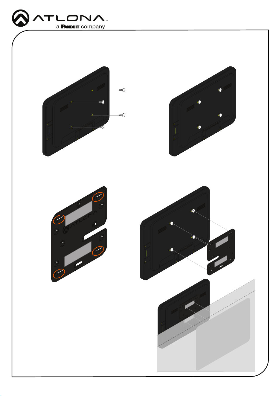
Mounting Instructions
In-wall
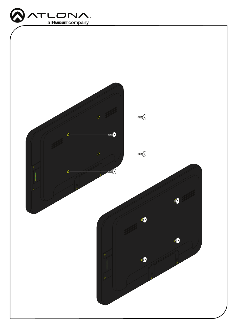
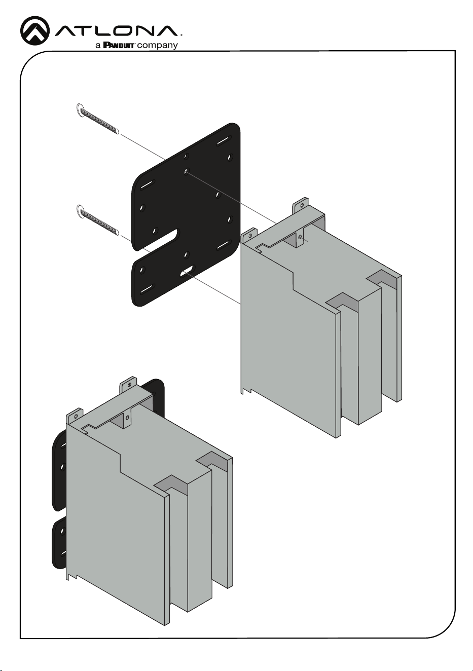
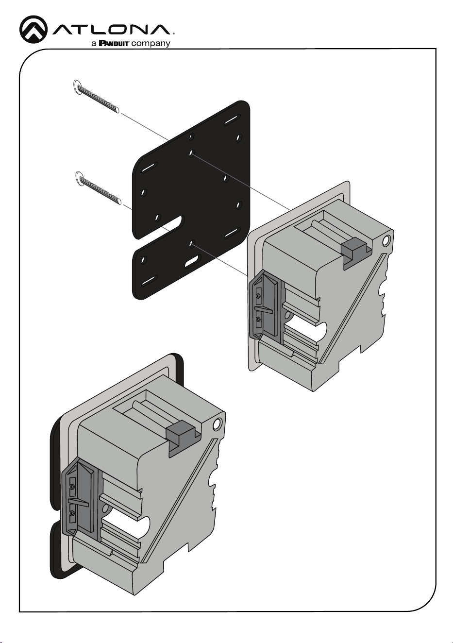
1 Connect the included mounting screws into the back of the wall plate. Do not over-tighten
the screws, as they should stick out a few mm from the wall plate for axing to the wall/
glass mount.
Installation Guide
AT-VTP-1000VL-BL and AT-VTP-1000VL-WH
3
2 Ax the wall/glass mount to the back box. This will dier per region.
US
Installation Guide
AT-VTP-1000VL-BL and AT-VTP-1000VL-WH
4
UK
Installation Guide
AT-VTP-1000VL-BL and AT-VTP-1000VL-WH
5
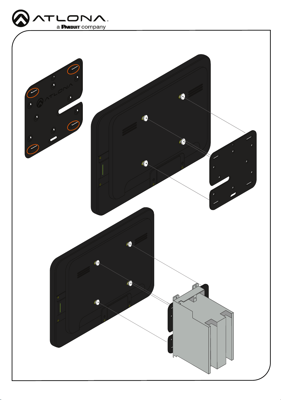
3 Align the screws on the back of the wall plate with the four large holes and slide them onto
the mounting plate.
UK
US
Installation Guide
AT-VTP-1000VL-BL and AT-VTP-1000VL-WH
6
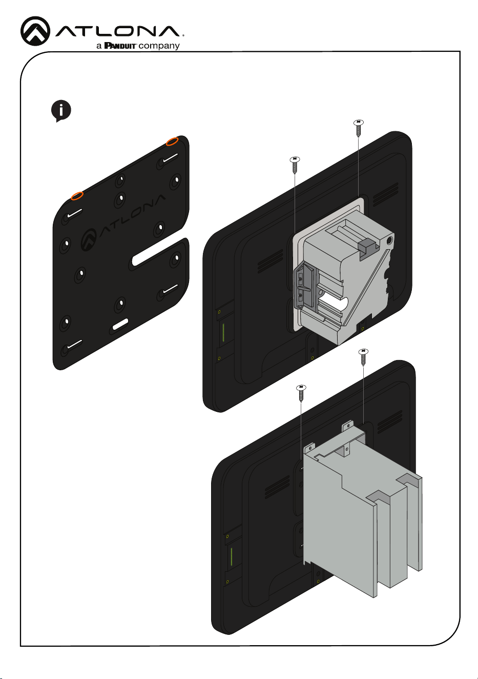
4 Insert the included safety screws into the top of the mounting plate, this will lock the
mounting screws into places.
NOTE: Tighten the screws by hand. To avoid damage to the touch panel, do not
overtighten.
Installation Guide
AT-VTP-1000VL-BL and AT-VTP-1000VL-WH
7
Glass Mounting
1 Connect the included mounting screws into the back of the wall plate. Do not over-tighten
the screws, as they should stick out a few mm from the wall plate for axing to the wall/
glass mount.
2 Remove the paper from one side of the double-sided tape and ax it to the back of the
mounting plate.
3 Align the screws on the back of the wall plate with the four large holes and slide them onto
the mounting plate.
4 *Optional* Ax the Glass Mount Cover Sticker to
the glass where the unit will be placed.
5 Remove the cover from the back of the double-
sided tape.
6 Gently press the unit and mount rmly to the glass
and hold pressure for thirty seconds to ensure the
tape is fully engaged.
Installation Guide
AT-VTP-1000VL-BL and AT-VTP-1000VL-WH
8
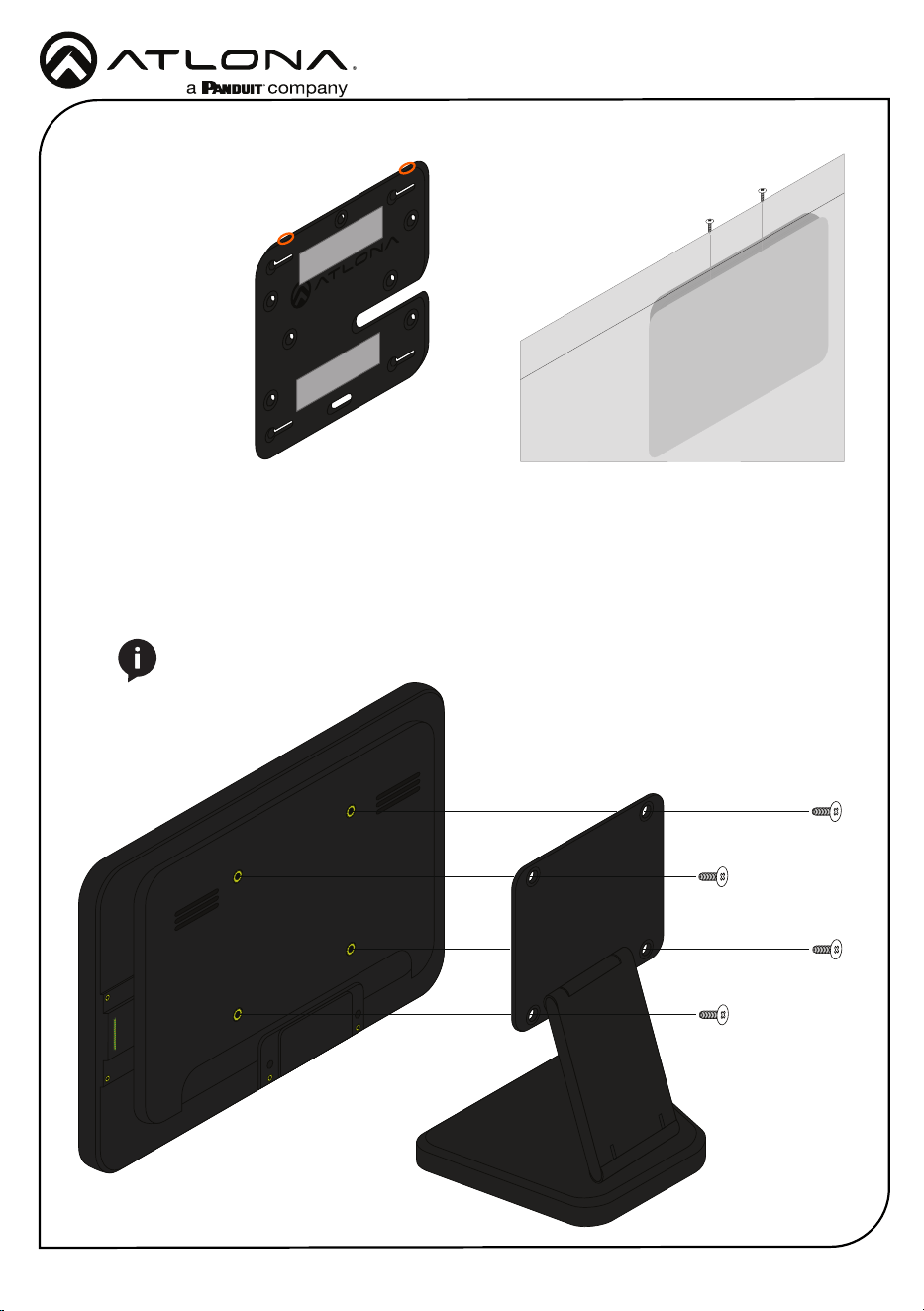
Table Mount (AT-VTP-VTM purchased separately through atlona.com)
1 Place the stand on the table/desk
2 Align the screw holes on the back of the wall plate with the holes on the adjustable stand.
3 Use the mounting screws included with the VTP-VTM and thread them through the back of
the stand into the wall plate.
NOTE: Tighten the screws by hand. To avoid damage to the touch panel, do not
overtighten.
7 Insert the included safety screws into the top of the mounting plate, this will lock the
mounting screws into places.
Installation Guide
AT-VTP-1000VL-BL and AT-VTP-1000VL-WH
9
Installation and Set Up
1 Connect the Ethernet cable into the back of the unit.
a If the Ethernet cable is connected to a non PoE switch, use a PoE injector using 802.3at
(purchased separately).
2 Secure the unit in either the wall or optional stand, as explained in the mounting instructions.
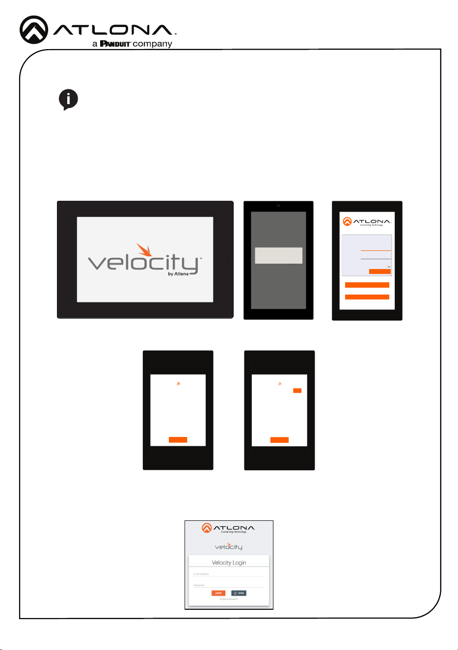
3 The Velocity logo will display during the booting process and will go directly into setup.
Press CONTINUE to start the setup process.
NOTE: Installation of the Velocity Touch Panel can only be done after Velocity has
been set up. View the installation guides for VGW-HW/VGW-SW and Velocity Manual
for instructions.
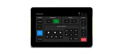
Initial Setup
CONTINUE
You will be guided through the setup process
in the next few screens.
Velocity Device Setup
Wired
Address
Device
Alias
Panel Settings
Velocity
URL
Enable
HTTPS
0.0.0.0
Velocity Touch Panel
10.0.0.123
SCAN FOR GATEWAYS
SAVE AND CONTINUE
PANEL SETTINGS
Scanning for Gateways
CANCEL
Scanning for Gateways
CANCEL
USE
10.0.0.234
4 The unit will load a new screen. Change the Device Alias (if needed) to help dierentiate
when there are multiple touch panels at a site. A new screen will open.
5 Press the SCAN FOR GATEWAYS button.
6 The touch panel will scan for new gateways. Once the correct gateway is found, press USE.
7 On a network computer, use a browser to log into Velocity.
Installation Guide
AT-VTP-1000VL-BL and AT-VTP-1000VL-WH
10
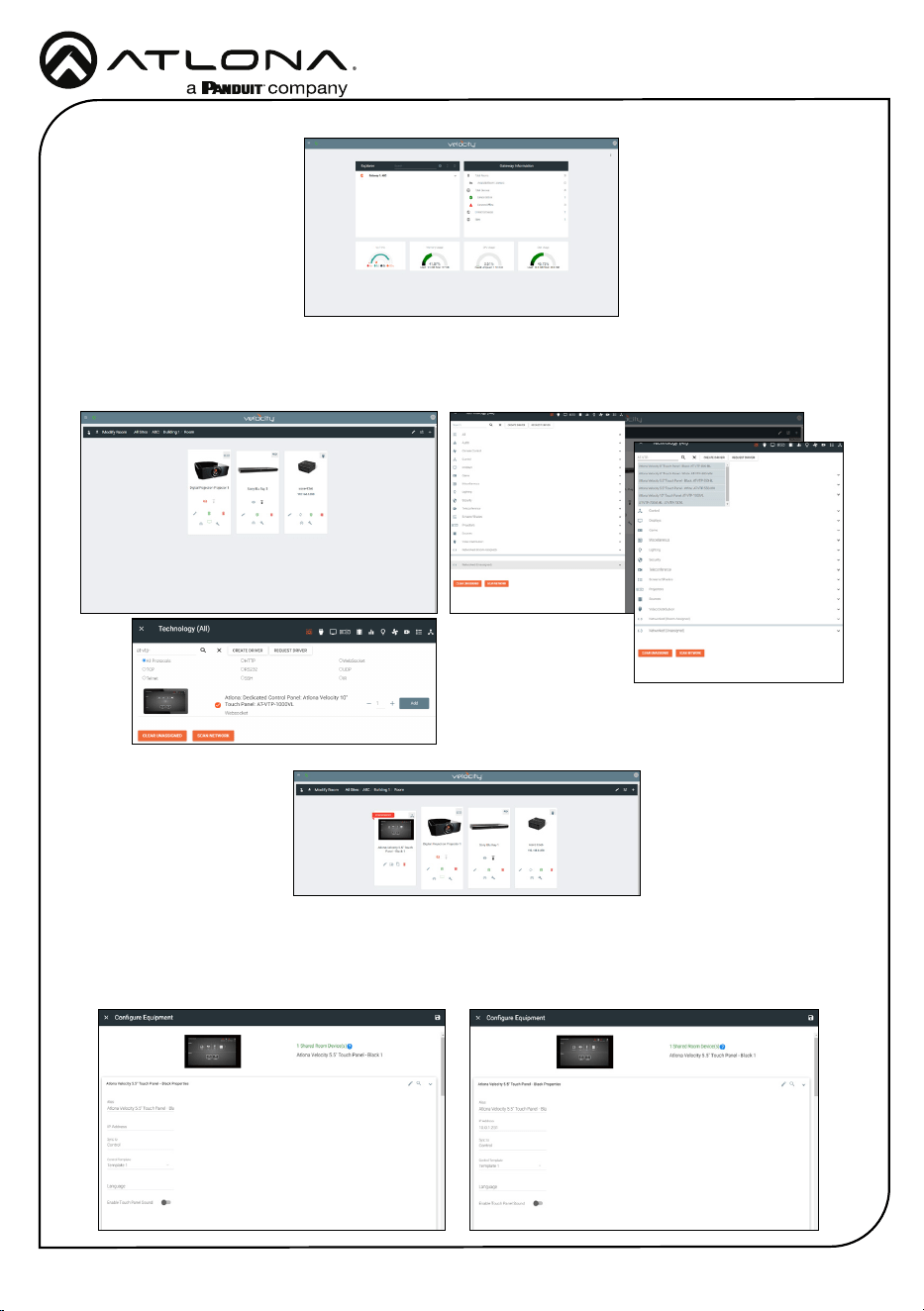
8 Navigate to the room the VTP will be located in.
9 Select the + button to add the unit.
10 Type the SKU into the search eld and select the correct panel from the drop down.
11 Select the Edit button on the tile to open the unit settings.
12 Select the ADD button. A tile for the unit will appear in the room.
13 Enter the IP of the VTP into the IP Address eld and select the save icon in the top right
corner of the screen. The screen will close, the panel will sync to the gateway, and the room
control will display on the panel.

Installation Guide
AT-VTP-1000VL-BL and AT-VTP-1000VL-WH
11
NOTE: The room must be completely set up to receive the control interface.
14 Depending on the room options there may be multiple buttons on the home page. Select the
any icon to open the room’s control page.
15 Select sources and displays by tapping on them or dragging and dropping the source on
the display.
Scheduling
The panel can be set to scheduling, to do this, continue from step 13 to the next few steps.
1 Select the Sync to drop down menu and
choose Scheduler.
2 Select the Save button. Once selected, the
Scheduler will appear on the panel.
Installation Guide
AT-VTP-1000VL-BL and AT-VTP-1000VL-WH
12
ABC
DEF
GHI JKL MNO
PQRS
TUV WXYZ
1 2 3
4 5 6
7 8
0
9
CANCEL
SAVE PIN
Set Configuration PIN
(Note: Once a pin is set, it will be required to edit settings going forward)
(Enter a blank pin to remove)
ADVANCED SETTINGS
Set Static IP
IP Address
Subnet Mask
Default Gateway
DNS Server
75.75.75.75
10.0.0.1
255.255.255.0
10.0.0.123
URL
Gateway Settings
Device Settings
Touch Screen LAN Configuration
0.0.0.0
Alternate URL
0.0.0.0
Alias
Velocity Touch Panel 800
SAVE
FACTORY RESET
CLEAR CACHE
SCAN NETWORK
CANCEL
SET PIN
Cache has been successfully cleared. Press
OK to restart.
OK
ADVANCED SETTINGS
Set Static IP
IP Address
Subnet Mask
Default Gateway
DNS Server
75.75.75.75
10.0.0.1
255.255.255.0
10.0.0.123
URL
Gateway Settings
Device Settings
Touch Screen LAN Configuration
0.0.0.0
Alternate URL
0.0.0.0
Alias
Velocity Touch Panel 800
SAVE
FACTORY RESET
CLEAR CACHE
SCAN NETWORK
CANCEL
SET PIN
Changing advanced settings requires application restart.
OK
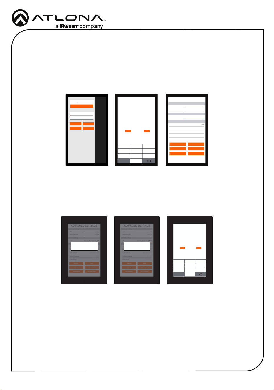
Within the advanced settings, all the touch pad settings can be changed or reset.
Gateway Settings -
a If the gateway IP is known, it can be typed into the URL eld.
b If the gateway IP is unknown, press the Scan Network button to search for and add
the gateway.
Device Settings - The touch pad can be renamed for easier syncing with Velocity. Type the
name into the Alias eld.
Touch Screen LAN Conguration - The current IP settings will display in these elds. To
switch to a static IP, select the Set Static IP slider, ll in the IP information, and press Save.
Set PIN - The default PIN of 554361 can be changed to a new pin by pressing the Set PIN
button. Type the new PIN in and press Save PIN.
Clear Cache - Press the Clear Cache button to release the current cache of the VTP. Press
the OK button to verify.
Factory Reset - Press the Factory Reset button to clear all the settings and start the touch
pad set up again. Press the OK button to verify.
Advanced Settings
Once the touch pad has been set up, the settings can be changed or reset only through the
advanced settings.
Verify your PIN
554361
ABC
DEF
GHI JKL MNO
PQRS
TUV WXYZ
1 2 3
4 5 6
7 8
0
9
CANCEL
VERIFY
URL
GATEWAY SETTINGS
TOUCH SCREEN SETTINGS
System Volume
Screen Brightness
0.0.0.0
REFRESH PAGE
CLEAN SCREEN
CLOSE
ABOUT VELOCITY
ADVANCED SETUP
1 To access the settings, swipe from the left side of the touch pad to the right.
2 Select Advanced Setup.
3 Type in the PIN. Default PIN is 554361.
ADVANCED SETTINGS
Set Static IP
IP Address
Subnet Mask
Default Gateway
DNS Server
75.75.75.75
10.0.0.1
255.255.255.0
10.0.0.123
URL
Gateway Settings
Device Settings
Touch Screen LAN Configuration
0.0.0.0
Alternate URL
0.0.0.0
Alias
Velocity Scheduling Panel 800
SAVE
FACTORY RESET
CLEAR CACHE
SCAN NETWORK
CANCEL
SET PIN
Installation Guide
AT-VTP-1000VL-BL and AT-VTP-1000VL-WH
13
Firmware Updating
URL
GATEWAY SETTINGS
TOUCH SCREEN SETTINGS
System Volume
Screen Brightness
0.0.0.0
REFRESH PAGE
CLEAN SCREEN
CLOSE
ABOUT VELOCITY
ADVANCED SETUP
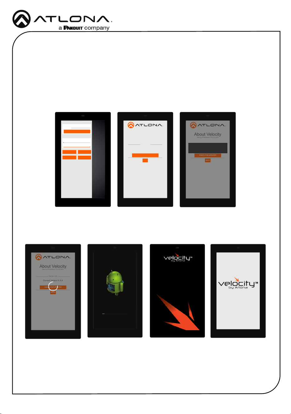
The touch panel can be updated from within its settings menu. To update, the panel must be
connected to a network with internet access.
1 Swipe from the left side of the touch pad to the right to open the gateway settings menu.
2 Select the ABOUT VELOCITY button. A new screen will take over.
3 Select the CHECK FOR UPDATES button. A pop up will appear if there is an update.
4 Press the YES on the touch screen for the unit to download and install the rmware.
About Velocity
Device IP Address 10.X.X.XXX
Version Info
Current Version X.X.X
CHECK FOR UPDATES
BACK
About Velocity
Device IP Address 10.X.X.XXX
Version Info
Current Version X.X.X
CHECK FOR UPDATES
BACK
Do you want to install the latest OS image on
this device?
NO YES
About Velocity
Device IP Address 10.X.X.XXX
Version Info
Current Version X.X.X
CHECK FOR UPDATES
BACK
Downloading image file from server to update
OS image.
About Velocity
Device IP Address 10.X.X.XXX
Version Info
Current Version X.X.X
CHECK FOR UPDATES
BACK
Installing system update...
Loading...
When the installation starts, it will switch to an Android update screen. Once completed it will
restart the touch panel. The splash screen will appear, before the loading screen takes over. The
update is complete when it returns to the control screen. This process can take up to 5 minutes
to complete.
Installation Guide
AT-VTP-1000VL-BL and AT-VTP-1000VL-WH
14
Version R2
© 2023 Atlona Inc. All rights reserved. “Atlona” and the Atlona logo are registered trademarks of Atlona Inc. All other brand names and trademarks or registered
trademarks are the property of their respective owners. Pricing, specications and availability subject to change without notice. Actual products, product images,
and online product images may vary from images shown here.
The English version can be found under the resources tab at:
https://atlona.com/product/at-vtp-1000vl/.
English Declaration of Conformity
Warranty
Chinese Declaration of Conformity 中国RoHS合格声明
To view the product warranty, use the following link or QR code:
https://atlona.com/warranty/.
由SKU列出於:
https://atlona.com/about-us/china-rohs/.
US International
atlona.com • 408.962.0515 • 41.43.508.4321