AT-VTP-700VL-BL
1
Installation Guide
Velocity 7” Touch Panel
AT-VTP-700VL-BL
1 x AT-VTP-700VL-BL
1 x Wall/Glass mount
4 x Mounting screws
2 x Safety screws
1 x Glass mount cover sticker
2 x Glass mount adhesive strips
1 x Installation Guide
Package Contents
Operating Notes
• The Velocity 7” Touch Panel (AT-VTP-700VL-BL) must be on the same network as the
Velocity Gateway (AT-VGW-HW or AT-VGW-SW) or it will be unable to sync for control.
• The AT-VTP-700VL is PoE capable, to power the unit, simply plug it into a 802.3at
compatible network switch. If the network switch is not PoE capable, a PoE injector
(purchased separately) can be used.
IMPORTANT: Velocity Gateway (AT-VGW-HW or AT-VGW-SW) must be set up before the
AT-VTP-700VL is fully functional.
The Atlona AT-VTP-700VL is a Velocity™ 7” touch panel with side mounted LED lighting. It
features contemporary, rened styling with 1024×600 native resolution and a capacitive glass
surface. The VTP-700VL is an ideal user interface for AV control or room scheduling in corporate
and education environments. Bright, side-mounted LED’s provide a visual representation of room
status or add emphasis to control functions. The panel ships with a dual-purpose one-gang wall
and glass mount kit, and its standard VESA 75 pattern provides compatibly with a wide variety
of other options. The optional AT-VTP-VTM tabletop mounting kit is available for placement on a
meeting table or lectern. The VTP-700VL features Power over Ethernet (PoE), enabling a single
network connection for data and power. Setting up the touch panel is easy, with room scheduling
and AV control GUIs automatically uploaded from the Velocity hardware or software server
gateway during system conguration.
AT-VTP-700VL-BL
2
Installation Guide
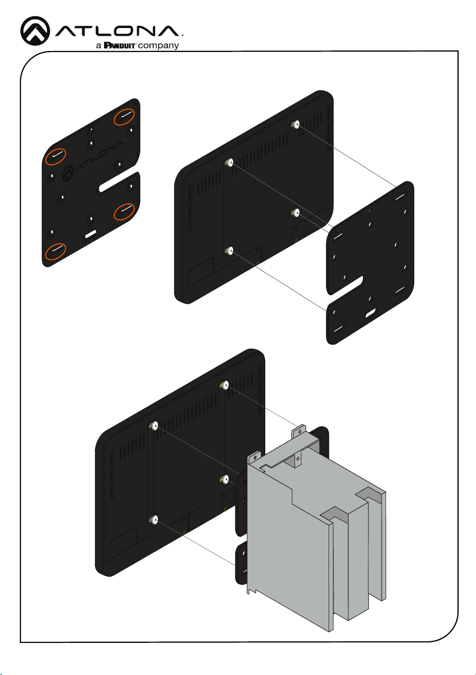
The AT-VTP-700VL has three mounting options. In-wall, an optional stand (AT-VTP-VTM, available
through atlona.com), and a ush mount kit (AT-VTP-FMK-7-BL, available through atlona.com).
Mounting Instructions
In-wall
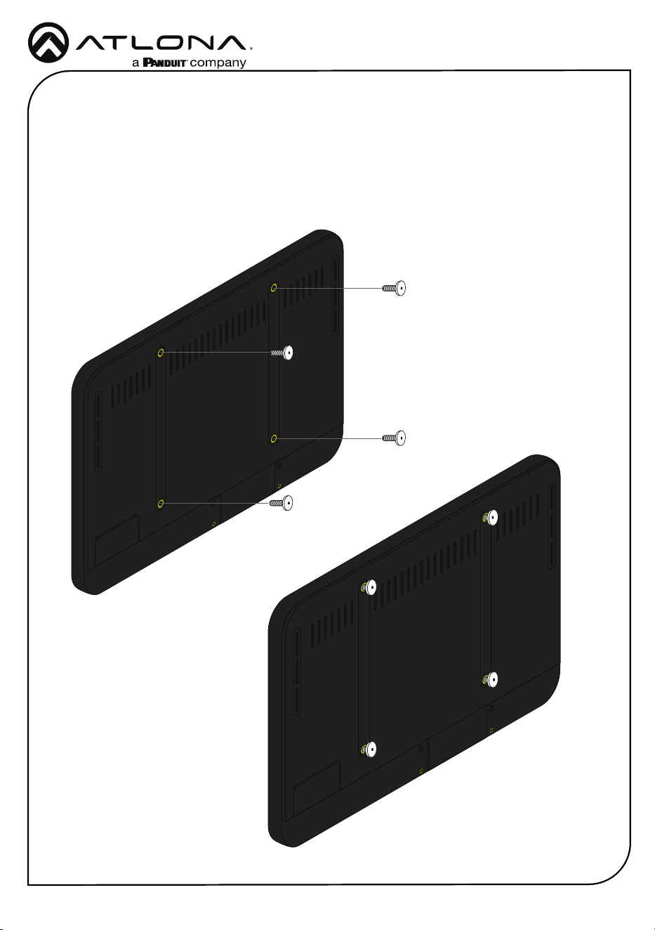
1 Connect the included mounting screws into the back of the wall plate. Do not over-tighten
the screws, as they should stick out a few mm from the wall plate for axing to the wall/
glass mount.

AT-VTP-700VL-BL
3
Installation Guide
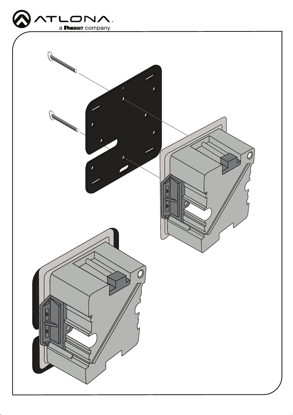
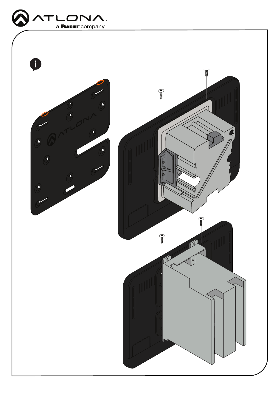
2 Ax the wall/glass mount to the back box. This will dier per region.
US
AT-VTP-700VL-BL
4
Installation Guide
UK
AT-VTP-700VL-BL
5
Installation Guide
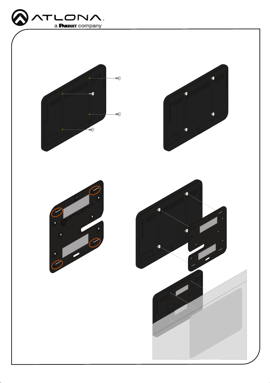
3 Align the screws on the back of the wall plate with the four large holes and slide them onto
the mounting plate.
AT-VTP-700VL-BL
6
Installation Guide
4 Insert the included safety screws into the top of the mounting plate, this will lock the
mounting screws into places.
NOTE: Tighten the screws by hand. To avoid damage to the touch panel, do not
overtighten.
AT-VTP-700VL-BL
7
Installation Guide
Glass Mounting
1 Connect the included mounting screws into the back of the wall plate. Do not over-tighten
the screws, as they should stick out a few mm from the wall plate for axing to the wall/
glass mount.
2 Remove the paper from one side of the double-sided tape and ax it to the back of the
mounting plate.
3 Align the screws on the back of the wall plate with the four large holes and slide them onto
the mounting plate.
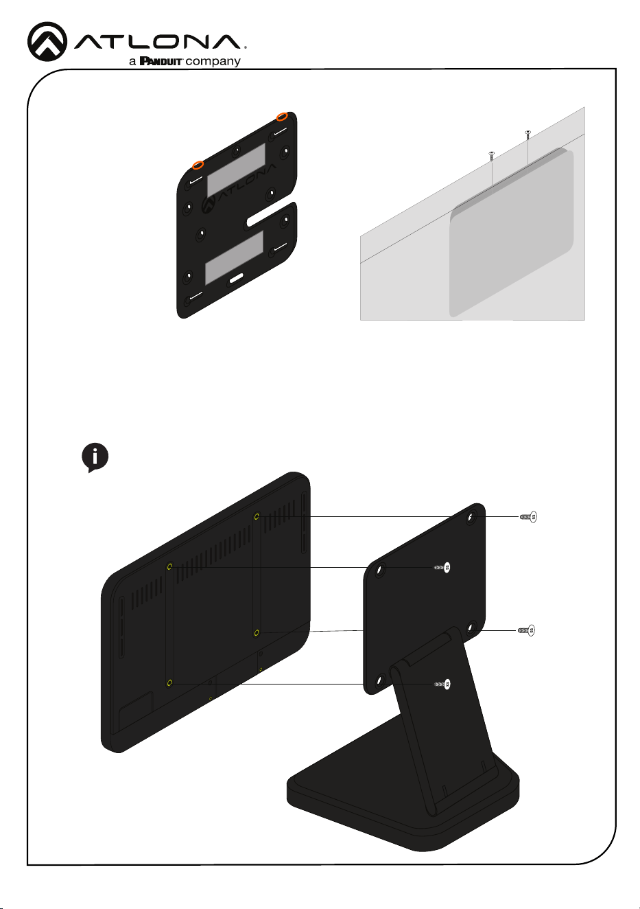
4 *Optional* Ax the Glass Mount Cover Sticker to
the glass where the unit will be placed.
5 Remove the cover from the back of the double-
sided tape.
6 Gently press the unit and mount rmly to the glass
and hold pressure for thirty seconds to ensure the
tape is fully engaged.
AT-VTP-700VL-BL
8
Installation Guide
Table Mount (AT-VTP-VTM purchased separately through atlona.com)
1 Place the stand on the table/desk
2 Align the screw holes on the back of the wall plate with the holes on the adjustable stand.
3 Use the mounting screws included with the VTP-VTM and thread them through the back of
the stand into the wall plate.
NOTE: Tighten the screws by hand. To avoid damage to the touch panel, do not
overtighten.
7 Insert the included safety screws into the top of the mounting plate, this will lock the
mounting screws into places.
AT-VTP-700VL-BL
9
Installation Guide
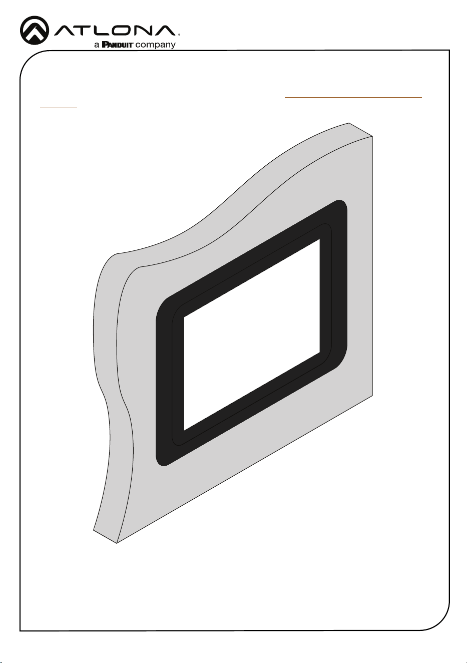
Flush Mount KIT (AT-VTP-FMK-7-BL purchased separately through atlona.com)
The optional AT-VTP-FMK-&-BL is available to purchase from https://atlona.com/product/at-vtp-
fmk-7-bl/ and provides a way to install the VTP-700VL ush with the wall.
AT-VTP-700VL-BL
10
Installation Guide
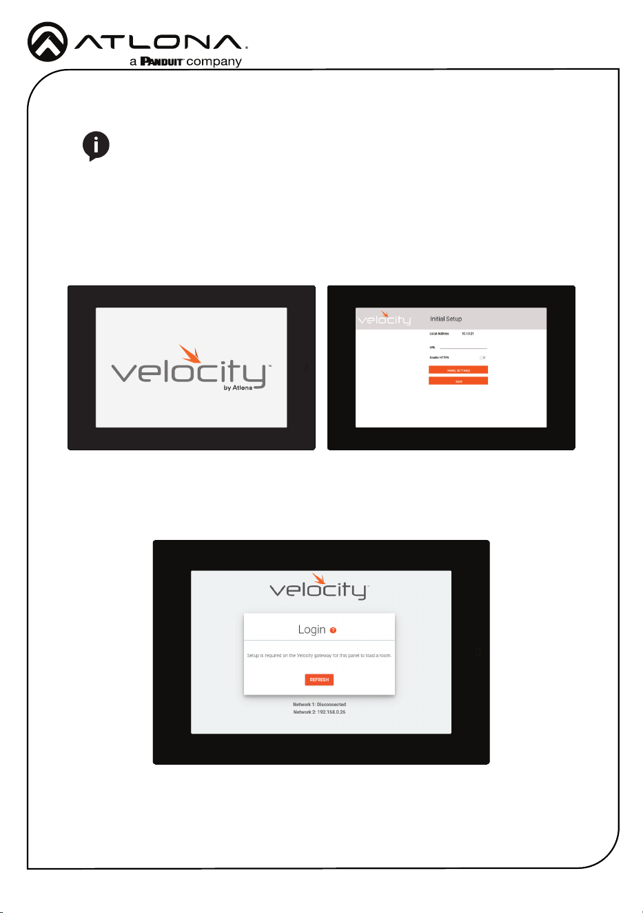
4 Enter the IP of the Velocity Gateway into the URL eld.
5 *Optional* Select the Enable HTTPS slider to enable protection on the VTP.
6 Press the SAVE button to start the syncing process with Velocity.
Installation and Set Up
1 Connect the Ethernet cable into the back of the unit.
a If the Ethernet cable is connected to a non PoE switch, use a PoE injector using 802.3at
(purchased separately).
2 Secure the unit in either the wall or optional stand, as explained in the mounting instructions.
3 The Velocity logo will display during the booting process and will go directly into setup.
NOTE: Installation of the Velocity Touch Panel can only be done after the VGW-HW
has been set up. View the AT-VGW-HW Installation Guide and Velocity Manual for
instructions.
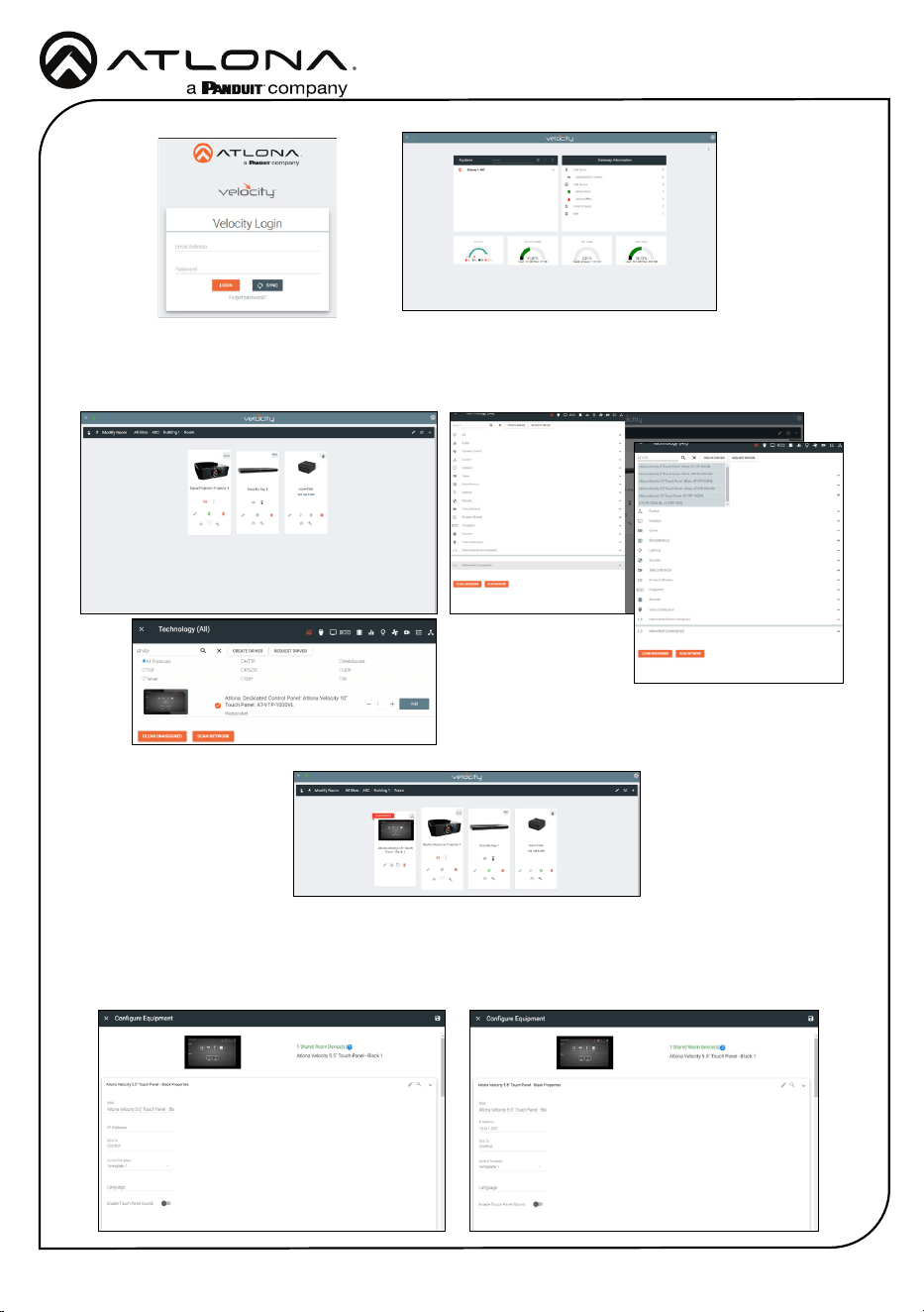
7 On a network computer, use a browser to log into Velocity.
AT-VTP-700VL-BL
11
Installation Guide
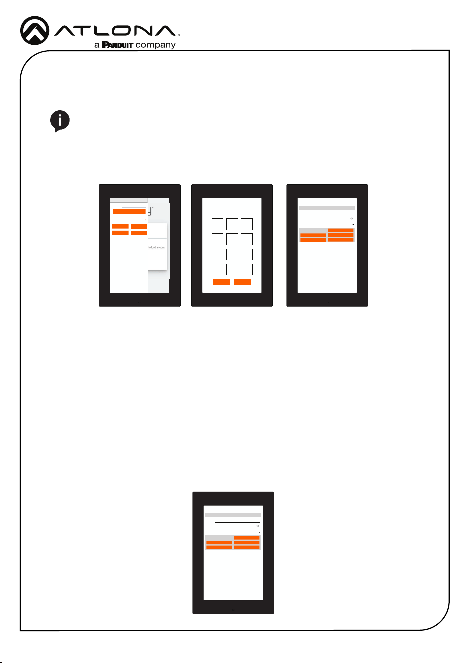
8 Navigate to the room the VTP will be located in.
9 Select the + button to add the unit.
10 Type the SKU into the search eld and select the correct panel from the drop down.
11 Select the Edit button on the tile to open the unit settings.
12 Select the ADD button. A tile for the unit will appear in the room.
13 Enter the IP of the VTP into the IP Address eld and select the save icon in the top right
corner of the screen. The screen will close, the panel will sync to the gateway, and the room
control will display on the panel.
AT-VTP-700VL-BL
12
Installation Guide
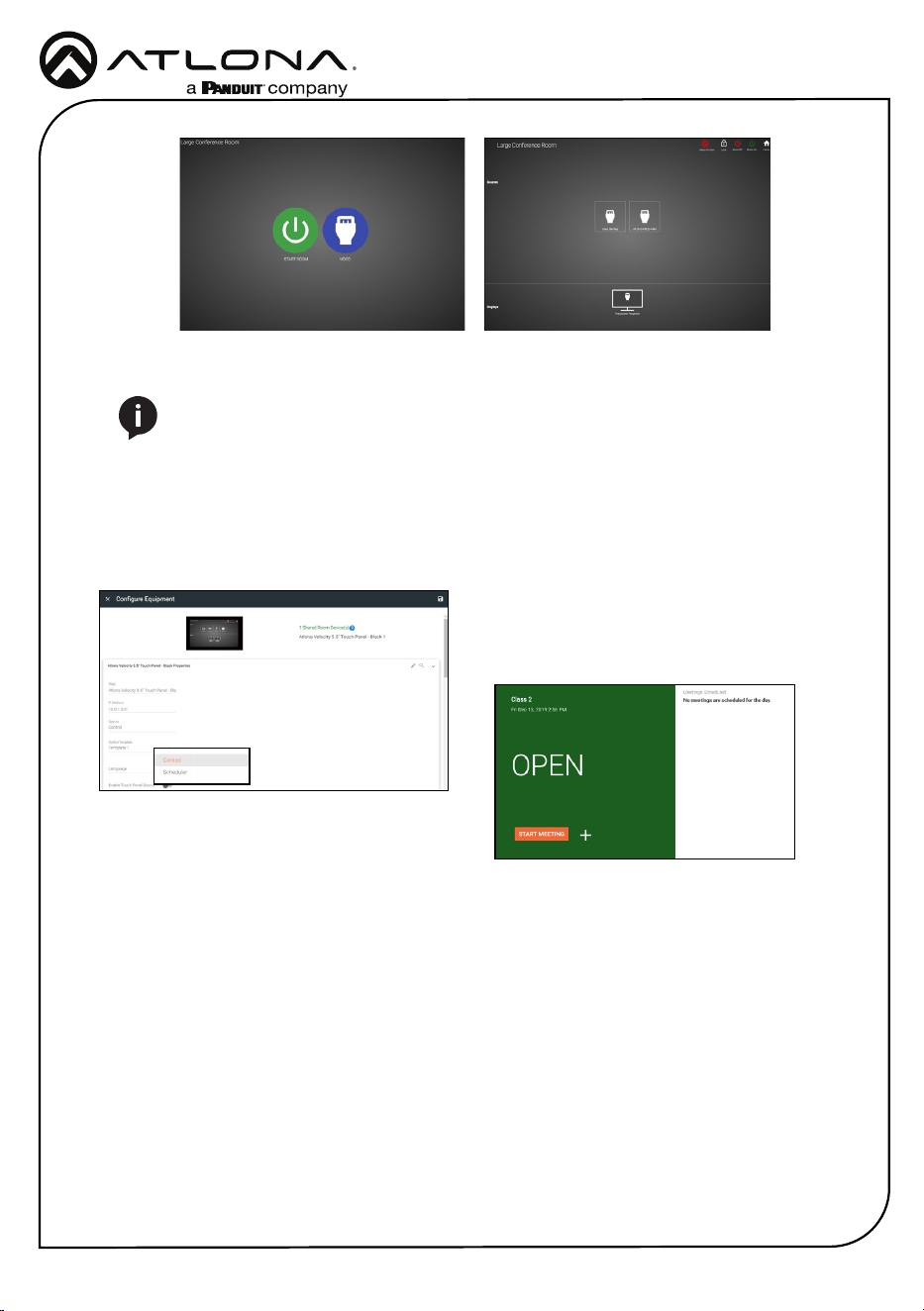
NOTE: The room must be completely set up to receive the control interface.
14 Depending on the room options there may be multiple buttons on the home page. Select the
any icon to open the room’s control page.
15 Select sources and displays by tapping on them or dragging and dropping the source on
the display.
Scheduling
The panel can be set to scheduling, to do this, continue from step 13 to the next few steps.
1 Select the Sync to drop down menu and
choose Scheduler.
2 Select the Save button. Once selected, the
Scheduler will appear on the panel.
AT-VTP-700VL-BL
13
Installation Guide
Within the advanced settings, all the touch pad settings can be changed or reset.
URL - Set the IP of the Velocity Gateway.
Enable HTTPS - Enable to set protection on the VTP.
Sleep Timer - This sets the timer for how long until the unit goes to sleep with inactivity.
Default is 10 minutes.
Cancel & Save - Conrm or reset the settings changed in the Advanced Settings.
Set PIN - The default PIN of 554361 can be changed to a new pin by pressing the Set PIN
button. Type the new PIN in and press Save PIN.
Panel Settings - Open up the android settings of the VTP to set time and change panel
Ethernet settings.
Factory Reset - Press the Factory Reset button to clear all the settings and start the touch
pad set up again. Press the OK button to verify.
Verify your PIN
554361
1 2 3
4 5 6
7 8 9
X 0 <-
OKCANCEL
URL
0.0.0.0
REFRESH PAGE
GATEWAY SETTINGS
Screen Brightness ###
CLEAN SCREEN
CLOSE
ABOUT
ADVANCED
2 Select Advanced Setup.
3 Type in the PIN. Default PIN is 554361.
Advanced Settings
URL
Gateway Settings
0.0.0.0
Enable HTTPS
SAVE
PANEL SETTINGS
FACTORY RESET
SET PIN
CANCEL
Sleep Timer 10 Minutes
Advanced Settings
URL
Gateway Settings
0.0.0.0
Enable HTTPS
SAVE
PANEL SETTINGS
FACTORY RESET
SET PIN
CANCEL
Sleep Timer 10 Minutes
Advanced Settings
Once the touch pad has been set up, the settings can be changed or reset only through the
advanced settings.
1 To access the settings, swipe from the left side of the touch pad to the right.
NOTE: Buttons may be oset in portrait mode, it is recommended to do advanced
settings in landscape.
AT-VTP-700VL-BL
14
Installation Guide
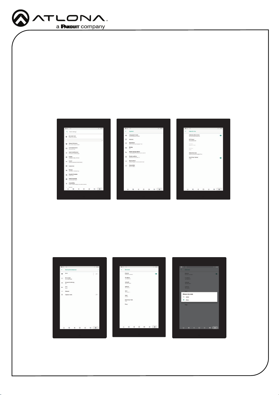
Within the panel settings, it is suggested to only change Ethernet and Time settings.
Select System, then Date & Time to update the panel time settings.
Automatic date & time - Enable or disable to have the time automatically update through the
NTP Server.
NTP Server - Default time server is set to android. This can be updated to a company server.
Set date & time - Manually set date and time when automatic date & time is disabled.
Select time zone - Set the VTP to the local time zone.
Use 24-hour format - When enabled, the VTP will be in 24-hour time format. When disabled,
the VTP will be in 12-hour time format.
Select Network & Internet, then Ethernet to update the IP settings.
Ethernet - Enable or disable the Ethernet port.
IP address, netmask, gateway, dns1, and dns2 - Will display current settings when set to
DHCP. Manually set information when set to static.
Ethernet Ip mode - Switch between Static and DHCP mode.
Proxy - Set up proxy settings.
AT-VTP-700VL-BL
15
Installation Guide
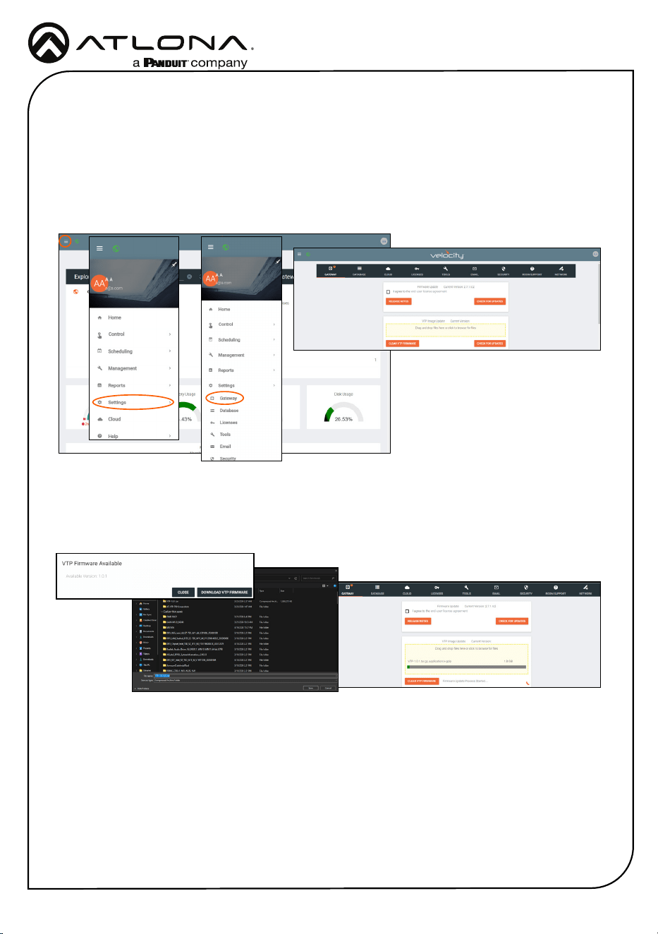
Firmware Updating
The touch panel is updated through Velocity. You can either download the rmware from atlona.
com or through Velocity.
The page will reload once the rmware is done updating.
1. Locate the ≡ in the top left corner of the home page and left click to open the menu.
2. Select Settings from the menu. New options will appear.
3. Select Gateway. A new screen will open.
4. Press the Check for Updates button under the VTP Image Update box to download the
rmware through Velocity, or download the rmware through atlona.com.
5. Once saved to the local computer, drag and drop the rmware into the VTP rmware eld.
The rmware will start updating automatically.
AT-VTP-700VL-BL
16
Installation Guide
Version 3
© 2024 Atlona Inc. All rights reserved. “Atlona” and the Atlona logo are registered trademarks of Atlona Inc. All other brand names and trademarks or registered
trademarks are the property of their respective owners. Pricing, specications and availability subject to change without notice. Actual products, product images,
and online product images may vary from images shown here.
US International
atlona.com • 408.962.0515 • 41.43.508.4321
The English version can be found under the resources tab at:
https://atlona.com/product/at-vtp-700vl-bl/.
English Declaration of Conformity
Warranty
Chinese Declaration of Conformity 中国RoHS合格声明
To view the product warranty, use the following link or QR code:
https://atlona.com/warranty/.
由SKU列出於:
https://atlona.com/about-us/china-rohs/.
25313-R3