
Operator’s Manual
SR-24 is used to refer to both the SR-24
and the SR-20 throughout this manual. The
SR-24 has integrated GPS and Bluetooth
®
technology. The SR-20 does not, but is oth-
erwise functionally identical.
SR
™
Locators
Original Instructions – English – 1
WARNING!
Read this Operator’s Man-
ual carefully before using
this tool. Failure to under-
stand and follow the con-
tents of this manual may
result in electrical shock,
fire, and/or serious per-
sonal injury.
SR-20
SeekTech

2 – English
Table of Contents
Introduction
Regulatory Statements ����������������������������������������������������������������������������������������������������������������������������������������������� 4
Safety Symbols �����������������������������������������������������������������������������������������������������������������������������������������������������������4
General Safety Rules
Work Area Safety ��������������������������������������������������������������������������������������������������������������������������������������������������������5
Electrical Safety ����������������������������������������������������������������������������������������������������������������������������������������������������������5
Personal Safety ����������������������������������������������������������������������������������������������������������������������������������������������������������5
Equipment Use and Care �������������������������������������������������������������������������������������������������������������������������������������������6
Pre-Operation Inspection
Specific Safety Information
SR‑24/SR‑20 Safety ��������������������������������������������������������������������������������������������������������������������������������������������������� 7
System Overview
Description �����������������������������������������������������������������������������������������������������������������������������������������������������������������7
Standard Equipment ���������������������������������������������������������������������������������������������������������������������������������������������������8
Components ���������������������������������������������������������������������������������������������������������������������������������������������������������������9
Operating Instructions
Quick Start ���������������������������������������������������������������������������������������������������������������������������������������������������������������� 10
Powering the System ������������������������������������������������������������������������������������������������������������������������������������������������ 11
Receiver Operation Modes ��������������������������������������������������������������������������������������������������������������������������������������� 11
Audio ������������������������������������������������������������������������������������������������������������������������������������������������������������������������ 12
Display Elements ������������������������������������������������������������������������������������������������������������������������������������������������������ 13
Understanding the Display ��������������������������������������������������������������������������������������������������������������������������������������� 17
Active Line Tracing
Direct Connect ���������������������������������������������������������������������������������������������������������������������������������������������������������� 19
Inductive Clamp �������������������������������������������������������������������������������������������������������������������������������������������������������� 19
Induction ������������������������������������������������������������������������������������������������������������������������������������������������������������������� 20
Induction and Air‑Coupling ����������������������������������������������������������������������������������������������������������������������������������������20
Tracing the Target Line ���������������������������������������������������������������������������������������������������������������������������������������������21
Confirming Accuracy �������������������������������������������������������������������������������������������������������������������������������������������������21
Passive Line Tracing
Passive Power ���������������������������������������������������������������������������������������������������������������������������������������������������������22
Passive Radio Frequency Broadband ���������������������������������������������������������������������������������������������������������������������22
OmniSeek ����������������������������������������������������������������������������������������������������������������������������������������������������������������23
Confirming Accuracy �������������������������������������������������������������������������������������������������������������������������������������������������23
Sonde Locating
Locating the Sonde ��������������������������������������������������������������������������������������������������������������������������������������������������24
Depth
Depth Verification Test ����������������������������������������������������������������������������������������������������������������������������������������������27
Depth Average ���������������������������������������������������������������������������������������������������������������������������������������������������������� 27
Improving and Confirming Accuracy
Signal Strength ���������������������������������������������������������������������������������������������������������������������������������������������������������29
Tracing Circuit ����������������������������������������������������������������������������������������������������������������������������������������������������������� 31
Confirming Accuracy �������������������������������������������������������������������������������������������������������������������������������������������������31

English – 3
Main Menu
Setting the Frequency �����������������������������������������������������������������������������������������������������������������������������������������������33
Bluetooth �����������������������������������������������������������������������������������������������������������������������������������������������������������������34
Connecting to a Transmitter with Bluetooth���������������������������������������������������������������������������������������������������������������37
Transmitter Control Screen ���������������������������������������������������������������������������������������������������������������������������������������38
SD Card ��������������������������������������������������������������������������������������������������������������������������������������������������������������������40
Units of Measurement ����������������������������������������������������������������������������������������������������������������������������������������������44
LCD Contrast ������������������������������������������������������������������������������������������������������������������������������������������������������������44
Custom Frequencies �������������������������������������������������������������������������������������������������������������������������������������������������44
Settings
IO Menu ��������������������������������������������������������������������������������������������������������������������������������������������������������������������48
SR‑24 GPS ��������������������������������������������������������������������������������������������������������������������������������������������������������������49
Customizing Display Elements ���������������������������������������������������������������������������������������������������������������������������������51
Information Options ��������������������������������������������������������������������������������������������������������������������������������������������������54
Maintenance and Support
Cleaning �������������������������������������������������������������������������������������������������������������������������������������������������������������������55
Accessories ��������������������������������������������������������������������������������������������������������������������������������������������������������������55
Transportation and Storage ��������������������������������������������������������������������������������������������������������������������������������������55
Service and Repair ���������������������������������������������������������������������������������������������������������������������������������������������������56
Disposal ��������������������������������������������������������������������������������������������������������������������������������������������������������������������56
Troubleshooting ��������������������������������������������������������������������������������������������������������������������������������������������������������57
Appendices
Appendix A: Glossary of Terms ��������������������������������������������������������������������������������������������������������������������������������58
Appendix B: Main Menu Map �����������������������������������������������������������������������������������������������������������������������������������60
Appendix C: Data Logging Abbreviations �����������������������������������������������������������������������������������������������������������������61
4 – English
Safety Symbols
In this operator’s manual and on the product, safety sym‑
bols and signal words are used to communicate import‑
ant safety information� This section is provided to im‑
prove understanding of these signal words and symbols�
This is the safety alert symbol� It is used to alert
you to potential personal injury hazards� Obey all
safety messages that follow this symbol to avoid
possible injury or death�
DANGER
DANGER indicates a hazardous situation which, if not
avoided, will result in death or serious injury�
WARNING
WARNING indicates a hazardous situation which, if not
avoided, could result in death or serious injury�
CAUTION
CAUTION indicates a hazardous situation which, if not
avoided, could result in minor or moderate injury�
NOTICE
NOTICE indicates information that relates
to the protection of property�
This symbol means read the operator’s manual
carefully before using the equipment� The oper‑
ator’s manual contains important information on
the safe and proper operation of the equipment�
This symbol means always wear safety glasses
with side shields or goggles when handling or
using this equipment to reduce the risk of eye in‑
jury�
This symbol indicates the risk of electrical shock�
Introduction
The warnings, cautions, and instructions dis-
cussed in this operator’s manual cannot cover
all possible conditions and situations that may
occur. It must be understood by the operator
that common sense and caution are factors
which cannot be built into this product, but must
be supplied by the operator.
Regulatory Statements
The EC Declaration of Conformity (890‑011‑
320�10) will accompany this manual as a sepa‑
rate booklet when required�
This device complies with Part 15 of FCC Rules�
Operation is subject to the following two condi‑
tions: (1) this device may not cause harmful in‑
terference, and (2) this device must accept any
interference received, including interference that
may cause undesired operation�
Contains Transmitter Module FCC ID: QOQWT41�

English – 5
General Safety Rules
WARNING
Read all safety warnings and instructions. Failure to
follow the warnings and instructions may result in
electric shock, fire, and/or serious injury.
SAVE THESE INSTRUCTIONS!
Work Area Safety
• Keep your work area clean and well lit. Cluttered or
dark areas invite accidents�
• Do not operate equipment in explosive atmo-
spheres, such as in the presence of flammable liq-
uids, gases, or dust. Equipment can create sparks
which may ignite the dust or fumes�
• Keep children and bystanders away while operat-
ing equipment. Distractions can cause you to lose
control�
Electrical Safety
• Avoid body contact with earthed or grounded sur-
faces such as pipes, radiators, ranges, and refrig-
erators. There is an increased risk of electrical shock
if your body is earthed or grounded�
• Do not expose equipment to rain or wet condi-
tions. Water entering equipment will increase the risk
of electrical shock�
• Keep all electrical connections dry and off the
ground. Do not touch equipment or plugs with wet
hands to reduce the risk of electrical shock�
Personal Safety
• Stay alert, watch what you are doing, and use com-
mon sense when operating equipment. Do not use
equipment while you are tired or under the influence of
drugs, alcohol, or medication� A moment of inattention
while operating equipment may result in serious per‑
sonal injury�
• Use personal protective equipment. Always wear
eye protection� The appropriate use of protective equip‑
ment such as a dust mask, non‑skid safety shoes, a
hard hat, and hearing protection will reduce personal
injuries�
• Do not overreach. Keep proper footing and balance
at all times� This enables better control of the equip‑
ment in unexpected situations�
• Dress properly. Do not wear loose clothing or jewelry�
Loose clothes, jewelry, and long hair can be caught in
moving parts�
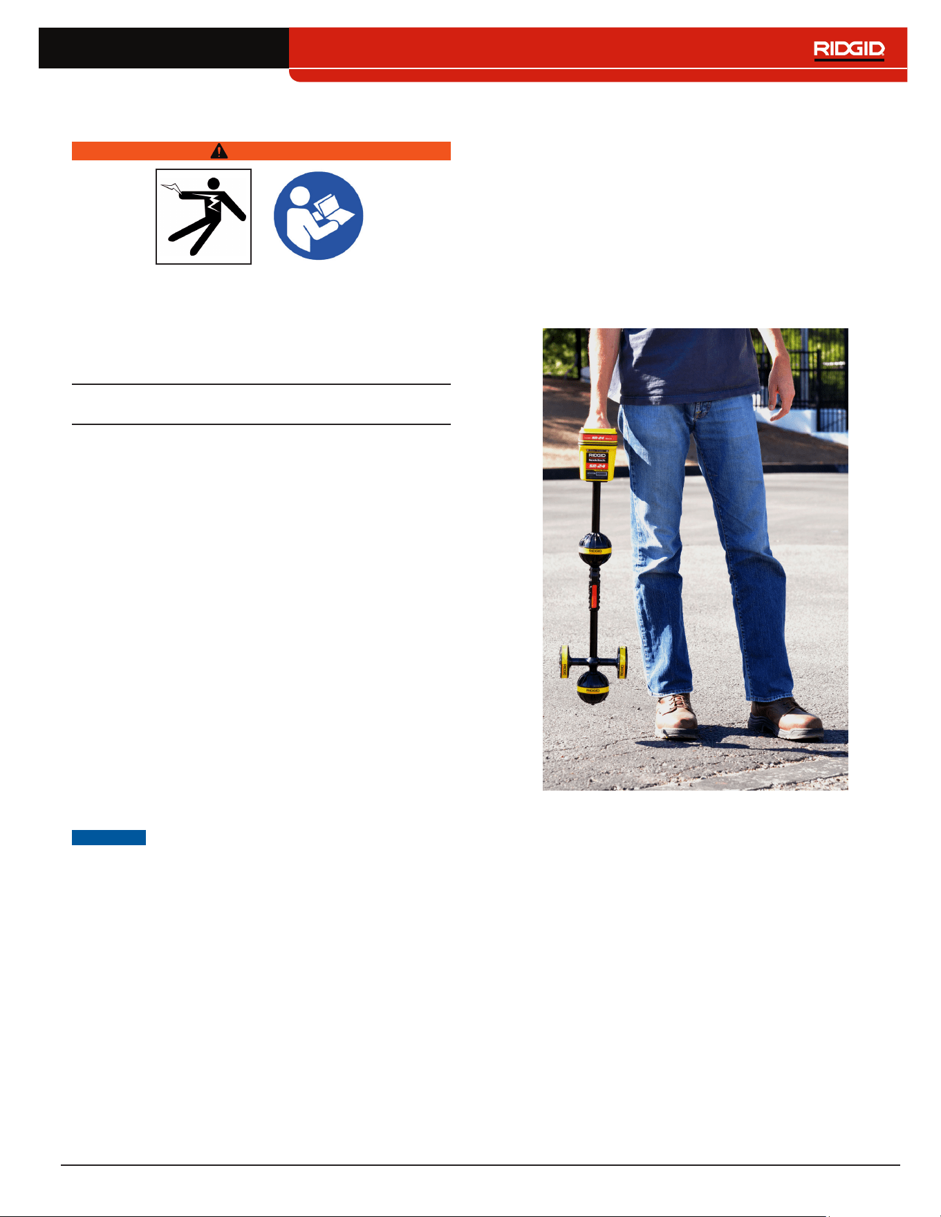
DANGER
• Avoid traffic. Pay close attention to moving vehicles
when using on or near roadways� Wear high‑visibility
clothing or reflector vests�

6 – English
Equipment Use and Care
• Do not force equipment. Use the correct equipment
for your application� The correct equipment will do the
job better and safer at the rate for which it is designed�
• Do not use equipment if the power switch does not
turn it on and off. Any equipment that cannot be con‑
trolled with the power switch is dangerous and must
be repaired�
• Disconnect the plug from the power source and/or
the battery pack from the equipment before mak-
ing adjustments, changing accessories, or storing.
Preventive safety measures reduce the risk of injury�
• Store idle equipment out of the reach of children
and do not allow persons unfamiliar with the equip-
ment or these instructions to operate the equip-
ment. Equipment can be dangerous in the hands of
untrained users�
• Maintain equipment. Check for misalignment or bind‑
ing of moving parts, missing parts, breakage of parts,
and any other condition that may affect the equip‑
ment’s operation� If damaged, have the equipment
repaired before use� Many accidents are caused by
poorly maintained equipment�
• Use the equipment and accessories in accordance
with these instructions; taking into account the
working conditions and the work to be performed.
Use of the equipment for operations different from
those intended can result in a hazardous situation�
• Use only accessories that are recommended by
the manufacturer for your equipment. Accessories
that may be suitable for one piece of equipment may
become hazardous when used with other equipment�
• Keep handles dry, clean, and free from oil and
grease. This allows for better control of the equipment�
Pre-Operation Inspection
WARNING
To reduce the risk of serious injury from electrical
shock or other causes, and to prevent damage to
your equipment, inspect all equipment and correct
any problems before each use.
To inspect all equipment, follow these steps:
1� Power off your equipment�
2� Disconnect and inspect all cords, cables, and con‑
nectors for damage or modification�
3� Clean any dirt, oil, or other contamination from your
equipment to ease inspection and to prevent it from
slipping from your grip during transportation or use�
4� Inspect your equipment for any broken, worn, miss‑
ing, misaligned or binding parts, or any other con‑
dition which might prevent safe, normal operation�
5� Check your work area for the following:
• Adequate lighting�
• The presence of flammable liquids, vapors, or
dust that may ignite� If present, do not work in
area until sources have been identified and cor‑
rected� The equipment is not explosion proof�
Electrical connections can cause sparks�
• A clear, level, stable, and dry place for the oper‑
ator� Do not use the equipment while standing
in water�
6� Examine the job to be done and determine the cor‑
rect equipment for the task�
7� Observe the work area and erect barriers or cones
as necessary to keep bystanders away and, if near
traffic, alert drivers�
English – 7
Specic Safety Information
WARNING
This section contains important safety information
that is specific to the SeekTech SR-24/SR-20. Read
these precautions carefully before using the SR-24/
SR-20 to reduce the risk of electrical shock, fire, or
other serious personal injury.
SAVE ALL WARNINGS AND INSTRUCTIONS
FOR FUTURE REFERENCE!
SR-24/SR-20 Safety
• Read and understand this operator’s manual and
the instructions for any other equipment in use in-
cluding, but not limited to, transmitters, clamps,
and sondes. Failure to follow all instructions and
warnings may result in property damage and/or seri‑
ous personal injury�
• Do not use this equipment if operator or SR-24/
SR-20 is standing in water. Operating the SR‑24/
SR‑20 while in water increases the risk of electrical
shock�
• Do not use where a danger of high voltage contact
is present. The SR‑24/SR020 is not designed to pro‑
vide high voltage protection and isolation�
• Exposing the utility is the only way to be certain of
its location. Several utilities may be underground in
the same area� Be sure to follow local guidelines and
One Call service procedures�
NOTICE
Ridge Tool Company, its affiliates and
suppliers, will not be liable for any injury
or any direct, indirect, incidental or con-
sequential damages sustained or in-
curred by reason of the use of the SR-24/
SR-20.
System Overview
Description
SR-24 is used to refer to both the SR-24 and the
SR-20 throughout this manual. The SR-24 has inte-
grated GPS and Bluetooth
®
technology. The SR-20
does not, but is otherwise functionally identical.
The RIDGID SeekTech SR‑24 receiver gives utility locat‑
ing professionals the information they need to confident‑
ly determine the position of underground utilities�
The SR‑24’s Omnidirectional antenna system measures
electromagnetic signals and calculates the signal’s ori‑
entation strength, depth, and degree of distortion or in‑
terference� The display and the multidimensional audio
cues give you a locating experience that is immediately
intuitive�
For an added degree of confidence, the SR‑24 continu‑
ously monitors the electromagnetic field for interference
from conflicting signals that could distort its shape� When
the SR‑24 detects distortion, the SR‑24 emits audio
cues and displays on‑screen guidance so that appropri‑
ate action can be taken to avoid mismarking the utility’s
position�
Built on the trusted and time tested SR‑20 platform, the
SR‑24 has integrated GPS and Bluetooth
®
technology,
giving a real‑time stream of data to Bluetooth enabled
devices, including smart phones, tablets, and high preci‑
sion GPS instruments�
8 – English
SeekTech SR-24 and SR-20 Specifications
Dimensions
Length 285mm [11�2in]
Width 109mm [4�3in]
Height 790mm [31�1in]
Weight without batteries 1�5kg [3�3lb]
Power
Power rating
6 V, 375 mA (SR‑20)
6 V, 450 mA (SR‑24)
Battery type
Four size C,
1�5V alkaline
(ANSI/NEDA 14A,
IEC LR14), or
1�2V NiMH or Ni‑
Cad rechargeable
batteries
Power consumption
2�25 W (SR‑20)
2�7 W (SR‑24)
LCD
Resolution
Monochrome
240 × 160 pixels
Display size
45mm × 65mm
[1�8 in × 2�6 in]
Contrast ratio 700:1
Brightness
500 Cd/m2
Environmental
Operating temperature
‑20°C to 50°C
[‑4°F to 122°F]
Storage temperature
‑20°C to 60°C
[‑4°F to 140°F]
Relative humidity 5% to 95%
USB
Cable Mini‑B, 1�8 m [6ft]
Type
2�0
SD Card Micro 16 GB
SeekTech SR-24 Specifications
Bluetooth
Type Class 1
Profile RFCOMM
Transmit power 19�1 dBm
Operating spectrum 2402 – 2480 MHz
Receiver sensitivity ‑92 dBm
Operating range
Up to 1,000m
[3,281ft]
GPS
Processor
48‑channel
SiRFstarIV GSD4e
Accuracy
<2�5m [8�2ft]**
Tracking ‑163 dBm
Autonomous acquisition ‑147 dBm
Operating spectrum 1559 – 1610 MHz
**According to the documentation supplied by the man-
ufacturer of the internal SiRFstarIV GPS module, its
nominal accuracy is “<2.5m (65 percent, 24 hour stat-
ic, -130dBm).”
Standard Equipment
• Operator’s manual
• Instructional DVD
• Four size C alkaline batteries
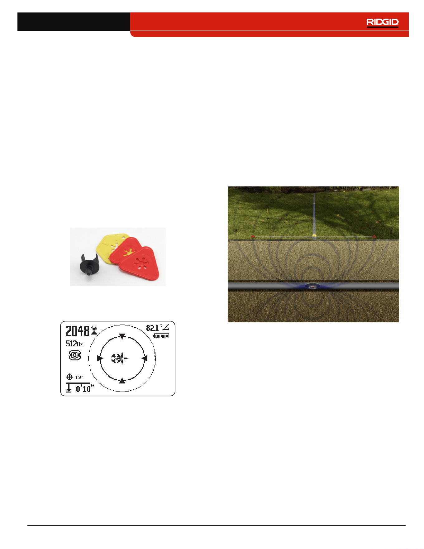
• Marker chips
• Mini‑B USB cable
English – 9
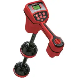
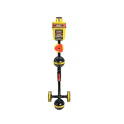
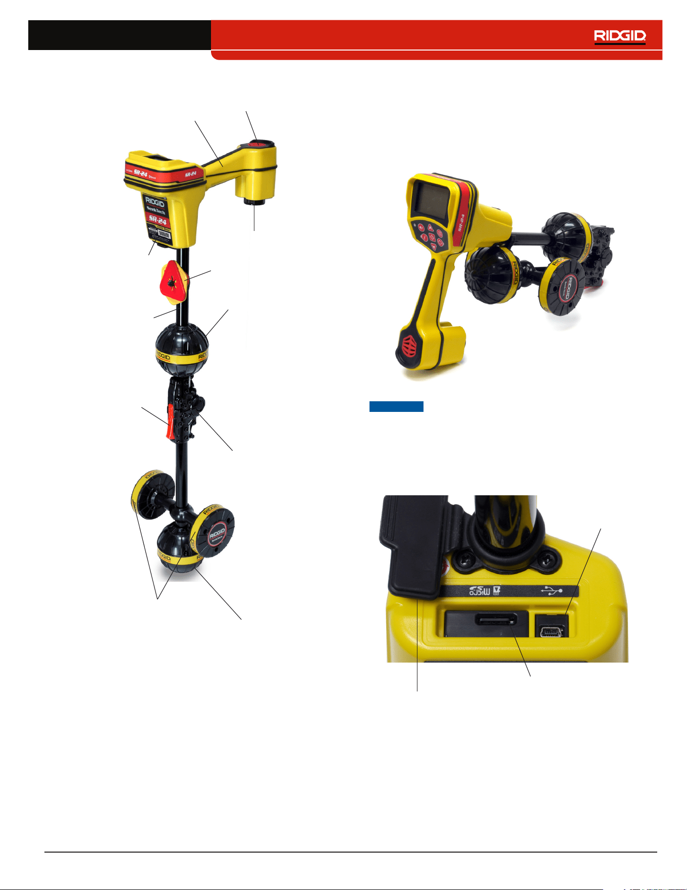
Components
Handle
Speaker
Antenna Mast
Upper Antenna
Folding Joint
Lower Antenna
Gradient Antennas
Release Latch
Battery Compartment
Serial Number Label
Marker Chips
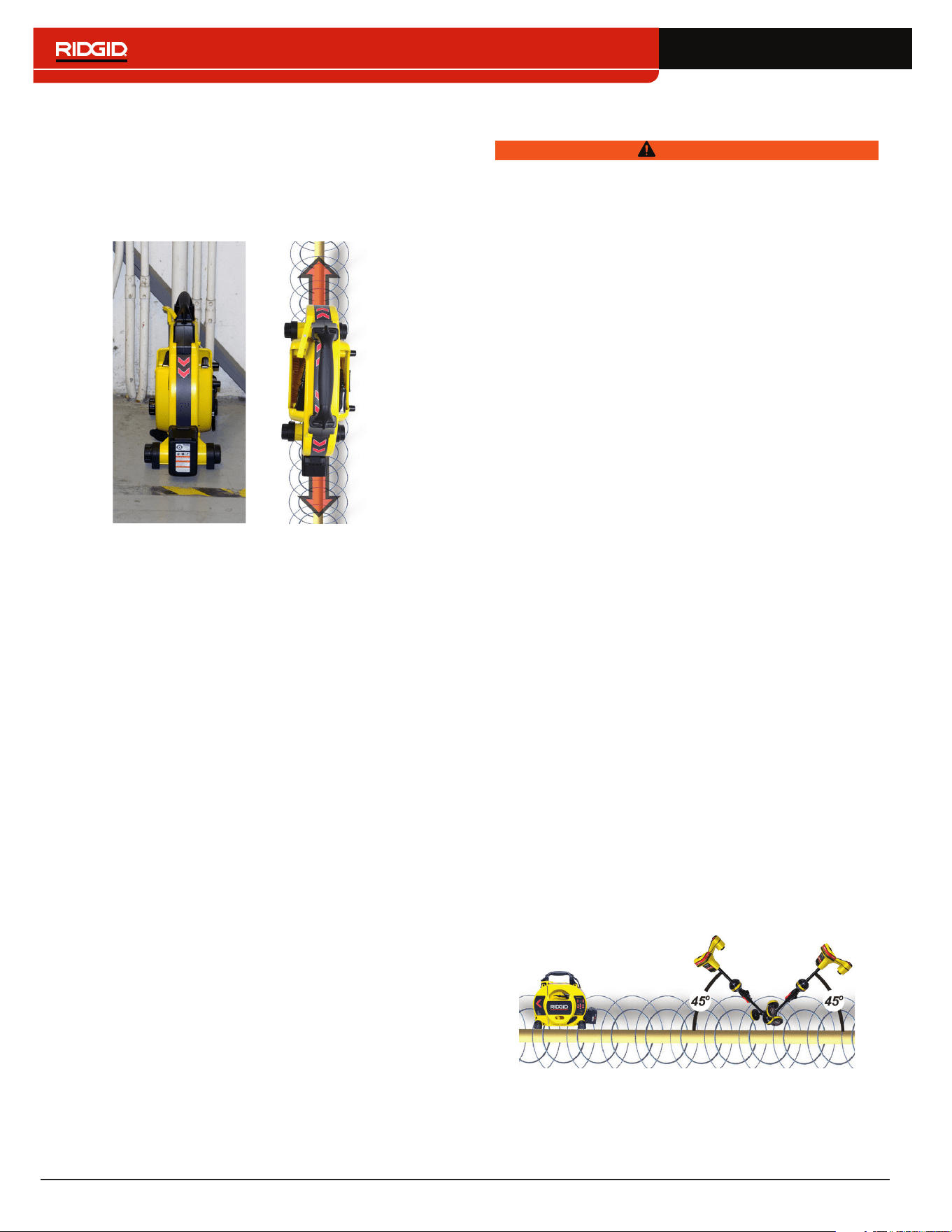
Folding Antenna Mast
Unfold the antenna mast and lock the folding joint into
place� When the job is complete, press the red release
latch to fold the antenna mast� Secure the folding mast
into the clip for storage or transportation�
NOTICE
You must unfold the antenna mast to use
the SR-24. To prevent damage to the
mast, do not snap or whip the SR-24 to
open or close it. Only open and close
the SR-24 manually.
USB Port Cover
USB Port
Micro SD Card Slot
10 – English
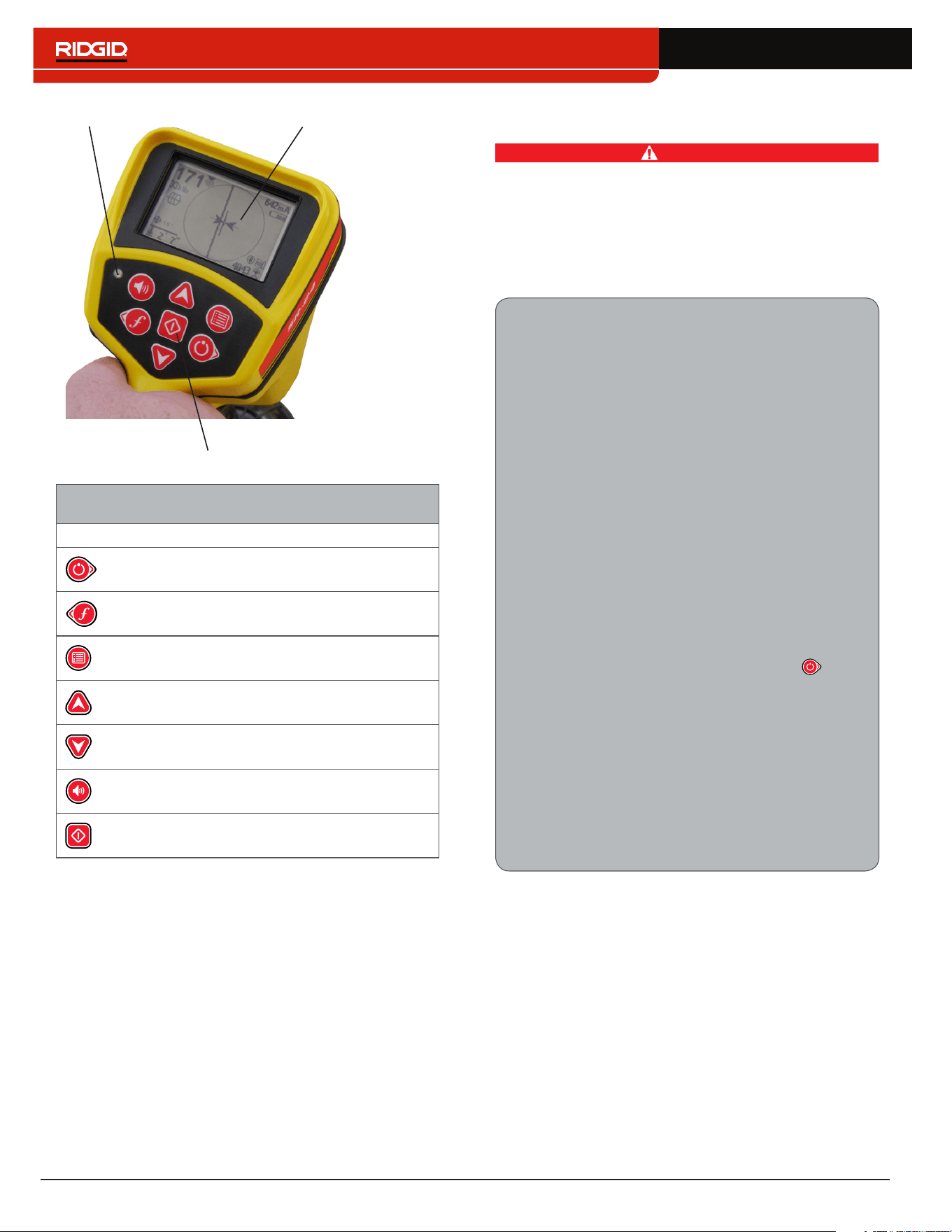
Keypad
Light Sensor LCD Screen
SR-24 Keypad
Key Function
Power Key/Right Arrow Key
Frequency Key/Left Arrow Key
Menu Key
Up Arrow Key
Down Arrow Key
Volume Key
Select Key
Operating Instructions
DANGER
Exposing the utility prior to digging is the only way
to verify its existence, location, and depth. If exca-
vating a utility, periodically recheck the measured
depth and position to avoid damaging the utility and
to identify additional utility signals that may have
been overlooked.
Quick Start
SR-24 is used to refer to both the SR-24 and the
SR-20 throughout this manual. The SR-24 has
integrated GPS and Bluetooth technology. The
SR-20 does not, but is otherwise functionally
identical.
The SR‑24 functions by measuring an electro‑
magnetic signal and estimating the position of its
source� The SR‑24 can locate the signal transmitted
by a RIDGID SeekTech transmitter or Sonde, other
manufacturer’s transmitters, or passive signals from
surrounding metallic conductors�
1� Insert four fully charged, size C, alkaline bat‑
teries into the battery compartment and turn
the knob clockwise to close�
2� Unfold the antenna mast and lock it into place�
3� Power on by pressing the Power Key �
4� Set the receiver and the transmitter to the
same frequency�
5� Begin tracing the line at a logical starting place
such as the transmitter hook up point�
Note: Refer to the Active Line Tracing, Passive Line
Tracing, and Sonde Locating sections that follow
for information on how to locate buried utilities with
the SR-24.
English – 11
Powering the System
Battery operation time varies with battery rating and use�
Four size C, alkaline batteries can power the SR‑24 for
10 to 15 hours�
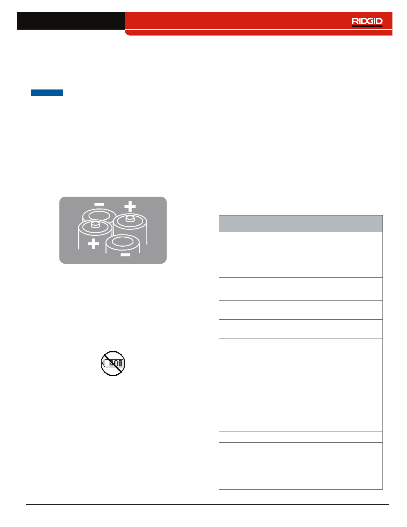
NOTICE
Use batteries that are all the same type.
Mixing alkaline and rechargeable batter-
ies can cause over heating and battery
leakage.
To install or change the batteries, follow these steps:
1� Turn the knob on the battery compartment count‑
er‑clockwise and pull straight out�
2� Insert four size C batteries as shown on the label in‑
side the battery compartment�
Note: Make sure the batteries drop completely into
the compartment.
3� Fit the cover back onto the battery compartment,
press the cover down, and turn the knob clockwise
to close�
Low Battery Warning
When the batteries are low, a low battery warning ap‑
pears on the screen and a tone sounds every 10 minutes
before the SR‑24 powers off� When the low battery warn‑
ing appears, replace the batteries�
Note: If you are using rechargeable batteries, the volt-
age may drop quickly at the end of its charge resulting
in a shortened warning period before power failure.
Receiver Operation Modes
The SR‑24 can operate using two modes: Line Trace
Mode and Sonde Mode�
Line Trace Mode
In Line Trace Mode you can Active Line Trace by inten‑
tionally applying a signal onto the target line through
metal‑to‑metal conduction or non metal‑to‑metal induc‑
tion with a transmitter�
Also in Line Trace Mode, you can Passive Line Trace
by detecting signal energy coupled onto metallic con‑
ductors from nearby energy sources such as power
lines� Passive Line Trace Mode includes Passive Power,
Radio Broadband, and OmniSeek Broadband Modes�
Broadband frequencies target any signal in a range of
frequencies�
Note: Active signals within a broadband range are also
detected.
Line Trace Mode
Active Frequencies
Default
128 Hz
1 kHz
8 kHz
33 kHz
User Programmable 10 Hz – 35 kHz
Passive Frequencies
Default North America
60 Hz
x9
< 4 kHz
Default Europe
50 Hz
x9
< 4 kHz
Default Japan
50 Hz
x9
60 Hz
x9
< 4 kHz
Power Preprogrammed
50 Hz
50
Hz
x5
50 Hz
x9
60 Hz
60 Hz
x5
60 Hz
x9
100 Hz
120 Hz
User Programmable 10 Hz – 35 kHz
Radio Frequency Broadband
4 kHz – 15 kHz
> 15 kHz
OmniSeek Broadband Modes
(All three simultaneously)
< 4 kHz
4 kHz – 15 kHz
> 15 kHz
12 – English
Sonde Mode
Use Sonde Mode to locate a sonde that is inside a pipe,
conduit, or tunnel�
Sonde Mode Frequencies
Default 512 Hz
Preprogrammed
16 Hz
640 Hz
850 Hz
8 kHz
16 kHz
33 kHz
User Programmable 10 Hz – 35 kHz
Note: Sonde Mode and Line Trace Mode can
sometimes use the same frequency. Make sure the
mode icon next to the frequency that you are using is
the mode you intend to be locating with. Depth mea-
surements will be in error if the incorrect mode is used.
User Programmable Custom Frequencies
The SR‑24 comes preprogrammed with a selection of
frequencies that are set by default in Active Line Trace
Mode, Passive Line Trace Mode, and Sonde Mode� You
can also create custom frequencies to use the SR‑24
with transmitters from most manufacturers�
Note: Refer to the Custom Frequencies section for more
information.
Audio
Volume Control
To increase and decrease the volume level of the SR‑24’s
audio cues, first press the Volume Key � You can then
either press the Volume Key to cycle through volume set‑
tings, or press the Volume Key once and use the Up
and Down Arrow Keys to adjust the volume set‑
tings� Press the Select Key to exit the volume settings
screen�
In all modes, if the sound level reaches its maxi‑
mum frequency range (pitch), it rescales to the mid‑
dle of its frequency range� The modulation of fre‑
quency is used to indicate signal strength�
Line Trace Modes
The SR‑24 emits sounds related to the estimated posi‑
tion of the utility� If the utility’s estimated position is on the
left side of the receiver, you will hear a warbling sound�
If the utility’s estimated position is on the right side of
the receiver, you will hear the same warbling sound plus
short clicks�
In Active Line Trace Mode and Passive Line Trace Mode,
the SR‑24 emits a higher pitch as it approaches the tar‑
get� The rising pitch indicates an increasingly strong
Signal Strength�
When local conditions distort the shape of the signal
field, the Tracing Line is fuzzy and the audio contains
static� The degree of fuzziness and the amount of static
in the audio reflect the amount of distortion detected in
the signal field�
Sonde Mode
In Sonde Mode the pitch rises and falls relative to chang‑
es in the Signal Strength� As the SR‑24 moves away from
the sonde, the pitch falls� As the SR‑24 moves closer to
the sonde, the pitch rises�
English – 13
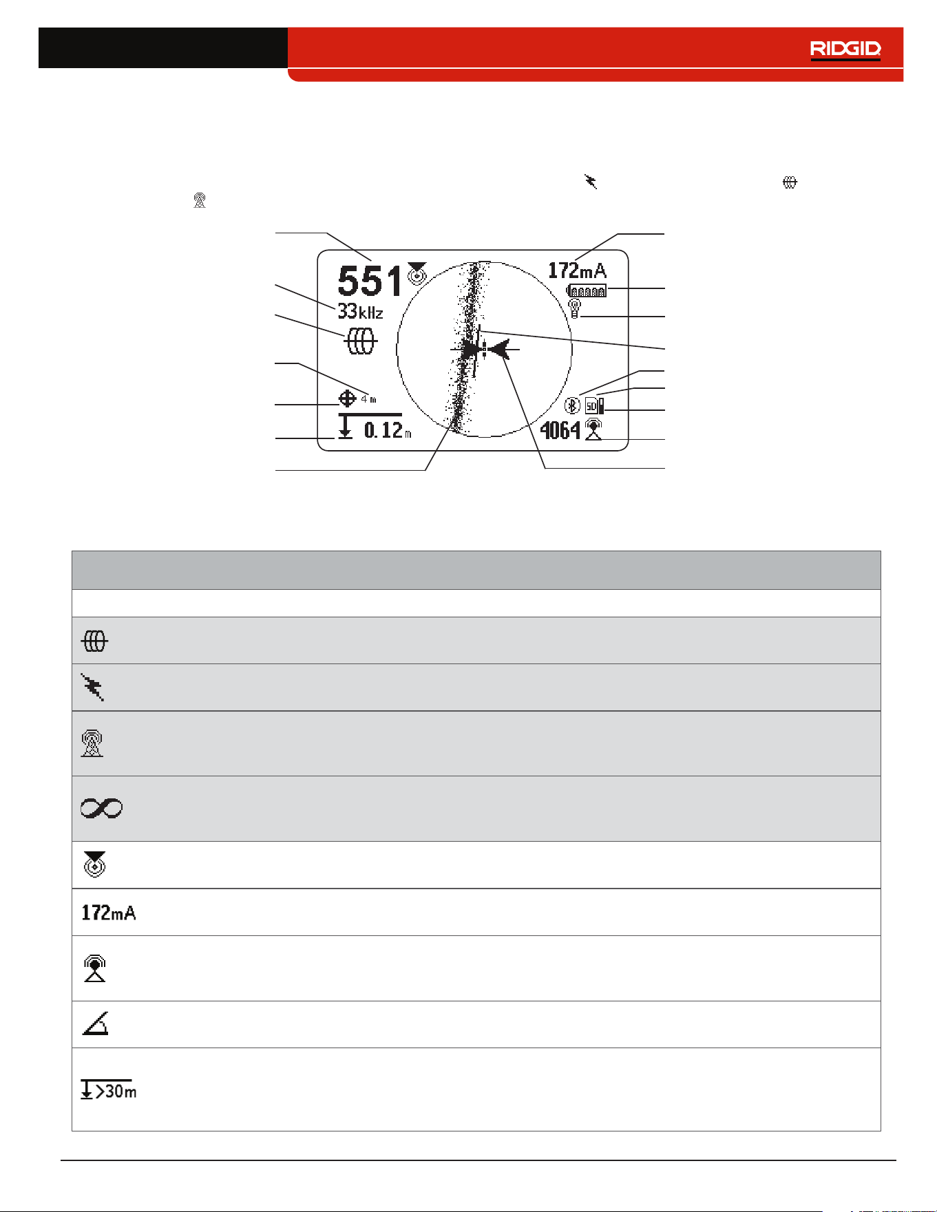
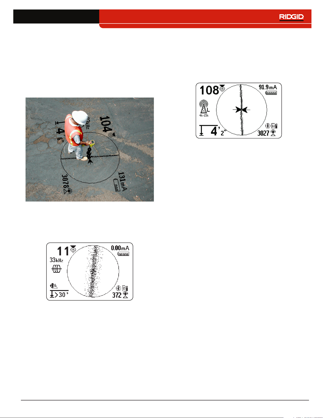
Display Elements
Line Trace Mode Display
The display elements shown below appear in Passive Line Trace Mode , Active Line Trace Mode , and Radio
Broadband Mode �
Proximity Number
Current Measurement (mA)
Battery Status
Receiver Operation Mode
Guidance Line
Guidance Arrows
Measured Depth
Tracing Line
(example shows distortion)
Signal Strength
Bluetooth
SD Card
Currently Set Frequency
GPS
GPS Estimated
Positional Error
Backlight
SD Card Usage Bar Graph
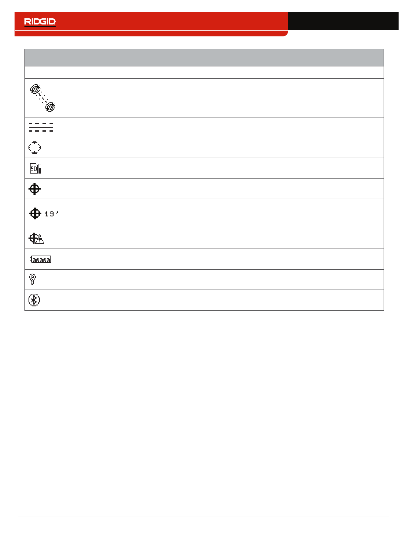
Line Trace Mode Display Elements
Icon Name Description
Active Line Trace
Mode
The Active Line Trace icon indicates the SR‑24 is set to an Active Line Trace
frequency�
Passive Power Line
Trace Mode
The Passive Line Trace icon indicates the SR‑24 is set to a Passive Power
Line Trace frequency�
Passive Radio
Frequency Broadband
Line Trace Mode
The Passive Radio Frequency Broadband Line Trace icon indicates the SR‑24
is set to a Passive Radio Frequency Broadband Line Trace frequency�
Passive OmniSeek
Line Trace Mode
The Passive OmniSeek Line Trace icon indicates the SR‑24 is set to a
Passive OmniSeek Line Trace frequency range� Refer to the OmniSeek
section for more information about OmniSeek Line Tracing.
Proximity Number
The Proximity Number represents the nearness of the target line to the SR‑24�
The larger the number, the closer you are to the target line�
Current Measurement
(mA)
Current Measurement (mA) appears in miliamps when the SR‑24 is directly
over the line�
Signal Strength
Strength of the signal detected by the Omnidirectional antennas� Observe the
Signal Strength to determine the maximum signal strength� At the maximum
signal strength, the receiver is over the target line�
Signal Angle
Signal Angle appears in place of Current Measurement (mA) when the
detected signal is at an angle greater than 35°�
Measured Depth
Measured Depth shows the approximate depth of the target line� The depth
appears in either meters (m) or feet (ft)� In addition to the measured depth
reading, Depth Average displays a Depth Average Report on screen� Refer to
the Depth Average section for more information.
14 – English
Line Trace Mode Display Elements
Icon Name Description
Tracing Line
The orientation and offset of the Tracing Line indicate the direction of the
target line relative to the position of the receiver� The Tracing Line Distortion
Response is enabled by default� When the Tracing Line Distortion Response
is enabled the Tracing Line also represents the amount of distortion detected
by the receiver and the approximate axis of the target line� Increasing levels of
field distortion are represented by increasing degrees of fuzziness�
Distortion Line
The Distortion Line represents the signal from the Upper Antenna node�
Compare the Tracing Line and the Distortion Line to estimate the degree of
distortion on the signal� The Distortion Line is disabled by default and only
appears if the Tracing Line Distortion response is disabled�
Guidance Arrows
When the Guidance Arrows are touching, they indicate the point where the
strength of the field is equal on both sides of the receiver�
Guidance Line
The Guidance Line shows the alignment of the Tracing Line and when the
orientation of the SR‑24 is close to the orientation of the utility�
Cross Hairs
The Cross Hairs are placed at the center of the Active View Area to represent
the receiver’s location�
Rotation Arrows
When the receiver is out of alignment with the target line, two rotation arrows
appear to indicate the direction you should turn the receiver to realign with
the target line� Correct orientation of the receiver is required for the Guidance
Arrows and Guidance Line to function properly� The Rotation Arrows only
appear when the receiver is not in line with the target line�
SD Card and Usage
Bar Graph
The SD Card and Usage Bar Graph icon indicates the SR‑24 is logging to the
installed SD Card� The Usage Bar Graph shows disk space usage�
GPS The GPS icon indicates the internal GPS feature is enabled�
GPS Estimated
Positional Error
GPS Estimated Positional Error is the number next to the GPS icon� It
indicates the Estimated Positional Error of the internal GPS� Refer to the
SR‑24 GPS section for more information�
No GPS Signal Lock Internal GPS signal is not locked and is searching for satellites�
Battery Status
The Battery Status icon indicates the amount of charge remaining in the
batteries�
Backlight The Backlight icon indicates the Backlight is on�
Bluetooth
The Bluetooth icon indicates the Bluetooth feature is enabled and the SR‑24
is connected to and paired with a Bluetooth enabled device�
English – 15
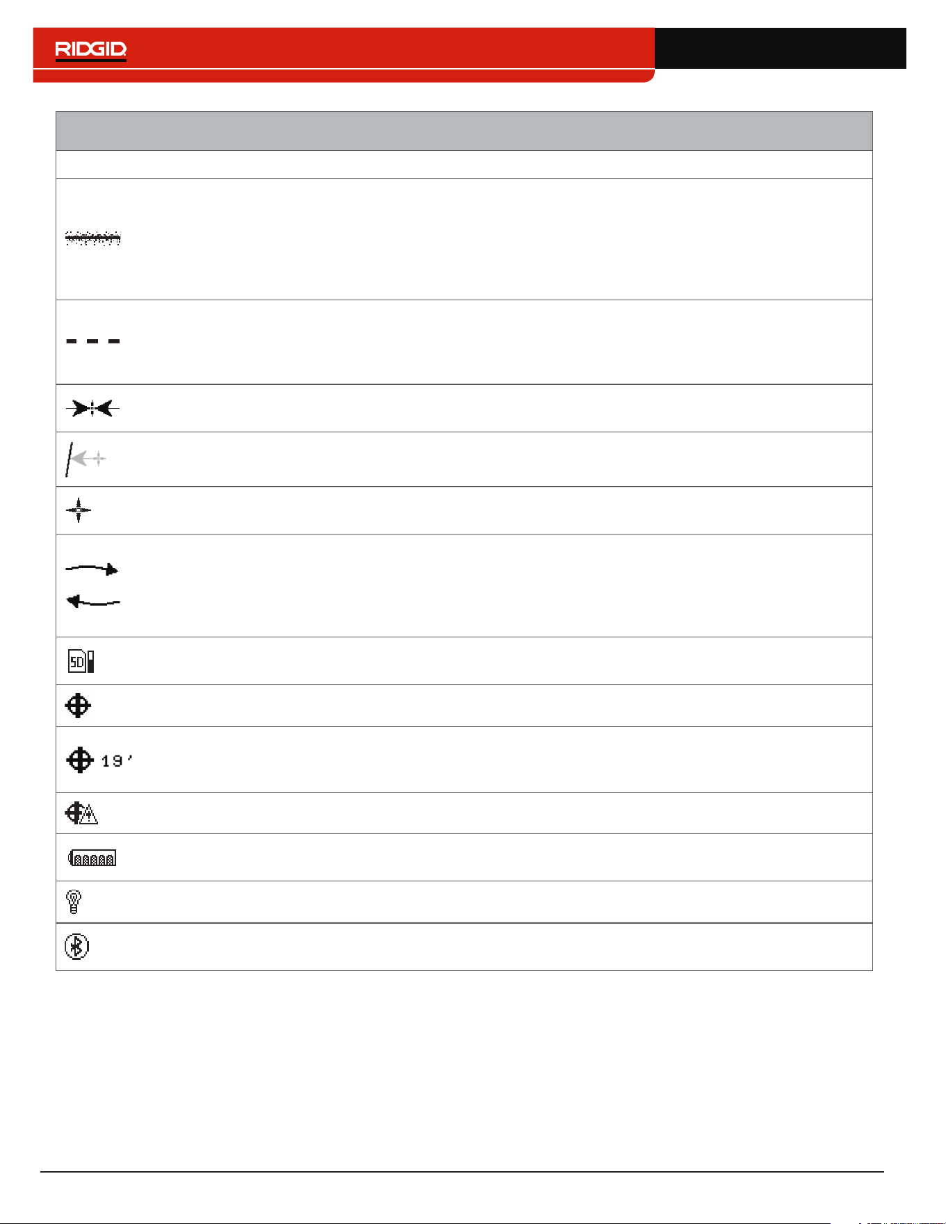
Sonde Mode Display
The display elements shown below appear in Sonde Mode �
Bluetooth
SD Card and Usage
Bar Graph
Signal Strength
Receiver Operation Mode
Pipe Direction
Pole
Zoom Ring
Cross Hairs
Signal Angle
Currently Set Frequency
Battery Status
Backlight
Measured Depth
GPS
GPS Estimated
Positional Error
Equator Line
SD Card and Usage
Bar Graph
Equator Line
Poles
Sonde Equator
No GPS Signal Lock
Bluetooth
Signal Strength
Currently Set Frequency
Receiver Operation Mode
Measured Depth
Battery Status
Signal Angle
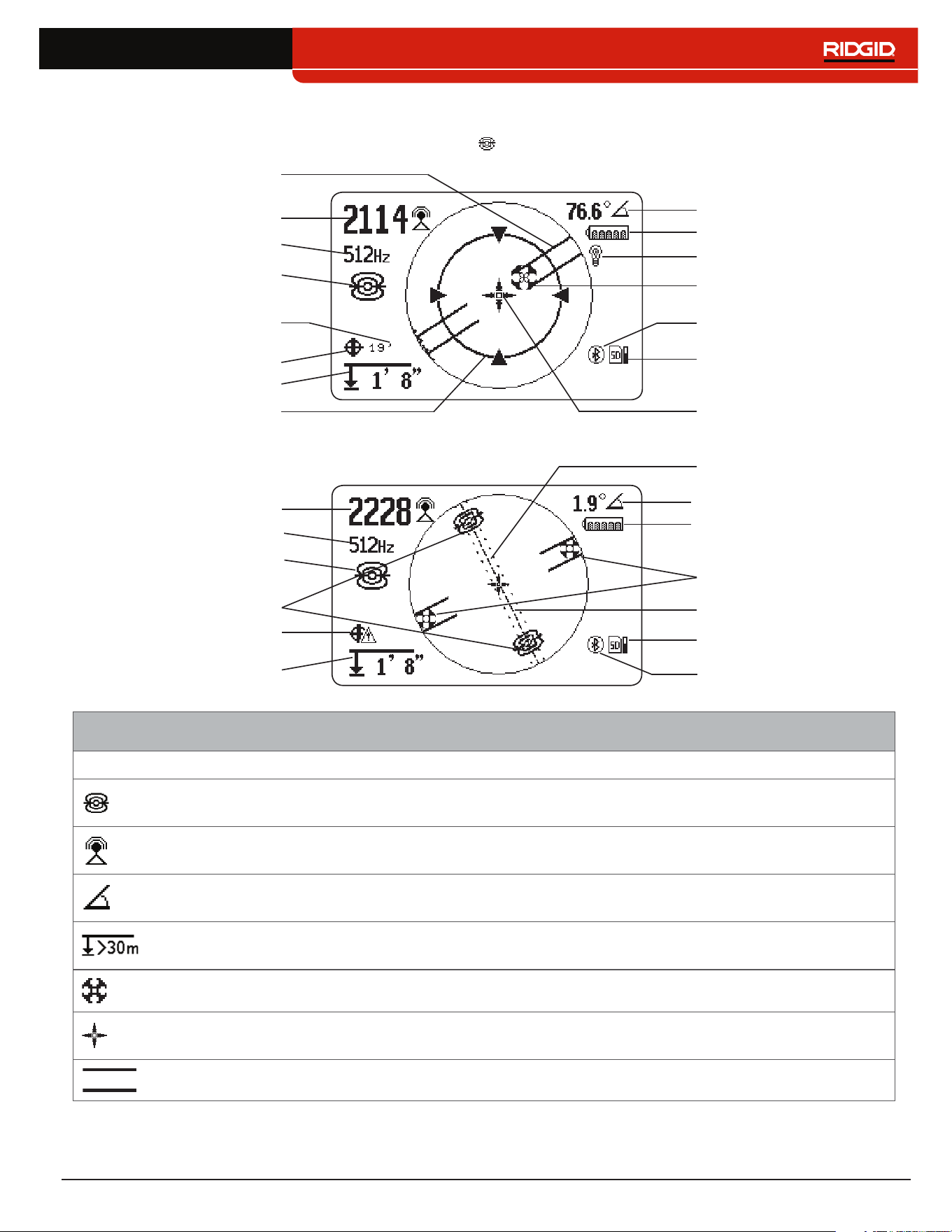
Sonde Mode Display Elements
Icon Name Description
Sonde Mode
The sonde icon underneath the currently set frequency, indicates the SR‑24 is
set to a sonde frequency�
Signal Strength
Strength of the signal detected by the omnidirectional antennas� Observe the
signal strength to determine the maximum signal strength�
Signal Angle
The signal angle displays the measured polar angle of the SR‑24 to the sonde
dipole field�
Measured Depth
Measured depth shows the approximate depth of the target line� The depth
appears in either meters (m) or feet (ft)�
Pole The pole icon represents the location of a pole of the sonde’s dipole field�
Cross Hairs
The cross hairs are placed at the center of the active view area to represent the
receivers location�
Pipe Direction The pipe direction represents the approximate orientation of the sonde’s axis�
16 – English
Sonde Mode Display Elements
Icon Name Description
Sonde Equator
Two sonde equator icons appear along the equator line once the first pole has
been located�
Equator Line The equator line represents the equator of the sonde’s field�
Zoom Ring The Zoom Ring appears when the receiver moves close to one of the Poles�
SD Card and Usage
Bar Graph
The SD Card and Usage Bar Graph icon indicates the SR‑24 is logging to the
installed SD Card� The Usage Bar Graph shows disk space usage�
GPS The GPS icon indicates the internal GPS feature is enabled�
GPS Estimated
Positional Error
GPS Estimated Positional Error is the number next to the GPS icon� It indicates
the Estimated Positional Error of the internal GPS� Refer to the SR-24 GPS
section for more information.
No GPS Signal
Lock
Internal GPS signal is not locked and is searching for satellites�
Battery Status
The Battery Status icon indicates the amount of charge remaining in the
batteries�
Backlight The Backlight icon indicates the Backlight is on�
Bluetooth
The Bluetooth icon indicates the Bluetooth feature is enabled and the SR‑24 is
connected to and paired with a Bluetooth enabled device�
Note: Refer to the Customizing Display Elements section for instructions on how to customize display elements and for
information about additional display options.
English – 17
Understanding the Display
Refer to the SR‑20 Instructional Video for a demonstra‑
tion of how the display elements work during a locate
and to see how they work together to make your locates
accurate and efficient� The video is on a DVD included
with the SR‑24 manual pack or can be viewed online:
www�RIDGID�com/us/en/instructional‑videos
Tracing Line
The Tracing Line shows the location and direction of the
target line’s signal, change in direction of the target line,
and the amount of distortion on the target line�
If the signal is clear and the detected field is undistorted,
the following occurs:
• The Tracing Line appears as a clear, single line�
• The Guidance Arrows point to the center of the
screen�
• The Guidance Line aligns with the Tracing Line�
If the Tracing Line appears fuzzy, the field may be distort‑
ed by interfering electromagnetic fields� As the distortion
increases, the Tracing Line appears increasingly fuzzy
and the audio cue increases static noise�
Guidance Arrows and the Guidance Line
The Guidance Arrows reflect the difference in the Signal
Strength measurement made on either side of the
SR‑24� They point in the direction of the strongest signal�
The Guidance Line appears between the arrows when
the receiver is aligned with the target line�
The Guidance Line gets longer as the receiver aligns
with the direction of the target line� For best guidance
accuracy, align the Tracing Line and Guidance Line be‑
tween the Guidance Arrows� As a general rule, if there
is a moderate mismatch between the Tracing Line and
Guidance Line, the Guidance Line will be closer to the
actual utility position� Any mismatch is an indication of
distortion�
18 – English
Distortion
Electromagnetic receivers like the SR‑24 require a sig‑
nal directly from the target utility without modification
by environmental factors to obtain optimal accuracy�
Environmental factors can include the presence of near‑
by metallic conductors or the addition of electromagnetic
fields from other sources like fields radiating from adja‑
cent utilities� These factors may distort the shape of the
field received by the SR‑24 and are experienced by the
SR‑24 as distortion� The SR‑24 uses its Omnidirectional
antennas and gradient antennas to measure distortion
and provide audio and on‑screen indicators�
Nearby metallic conductors can distort the shape of the
target line’s electromagnetic field� The SR‑24 gives three
different indicators to alert you that distortion is present�
Take extra precautions when distortion is present to
confirm the accuracy of the locate.
Note: Refer to the Improving and Confirming Accuracy
section for information on improving the locate.
The Tracing Line Distortion Response activates when dis‑
tortion is detected� The Tracing Line Distortion Response
makes the Tracing Line appear fuzzy when distortion is
present� The fuzzier and more spread out the Tracing
Line is, the greater the distortion�
You can set the Tracing Line Distortion Response to
high “H,” medium “M,” low “L” (default), or “OFF�” Set the
Tracing Line Distortion Response to high to increase its
sensitivity to distortion�
Note: To change the Tracing Line Distortion Response
sensitivity settings, refer to the Customizing Display
Elements section.
When the Distortion Line is enabled, the tracing line fuzz‑
iness is turned off� The Tracing Line becomes a solid line
and the Distortion Line (dashed line) appears when dis‑
tortion is present� The dashed Distortion Line represents
the signal detected by the Upper Antenna and the solid
Tracing Line represents the signal detected by the Lower
Antenna�
Distortion is likely if the Distortion Line does not align
with the Tracing Line� The Distortion Line and the Tracing
Line may move randomly if the SR‑24 receives a weak
signal�
English – 19
Active Line Tracing
In Active Line Tracing Mode, the SR‑24 detects signals
generated by a line transmitter, such as the RIDGID
SeekTech ST‑33Q+� Transmitters can energize a target
line with a tracing signal in three ways: Direct Connect
(metal‑to‑metal contact), with an Inductive Clamp, or
using the transmitter’s internal transmitting antenna
through Induction�
Note: For complete instructions on generating a locating
signal with a transmitter, refer to the operator’s manual
that came with the line transmitter you are using.
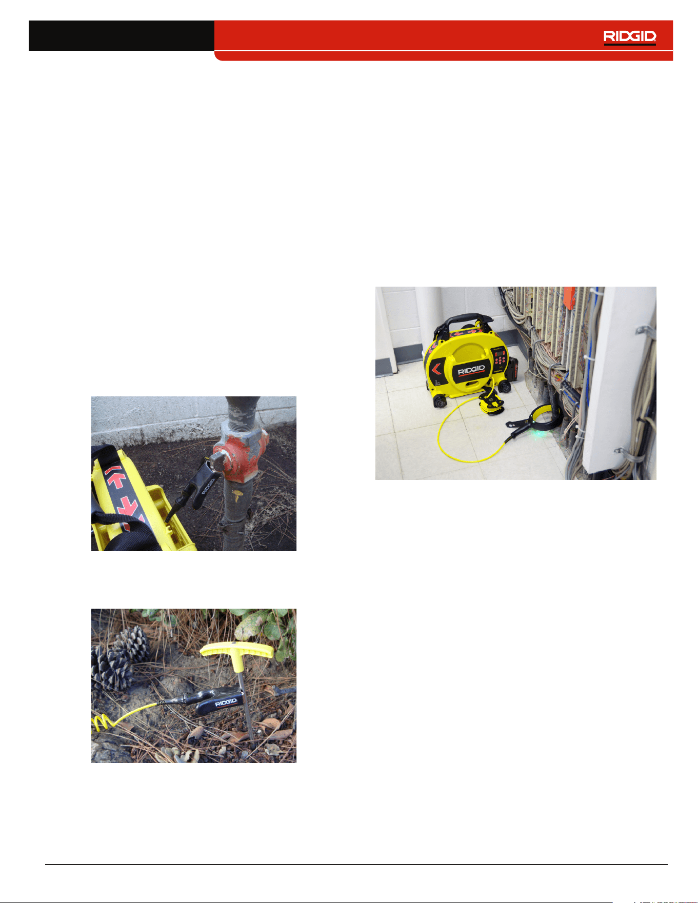
Direct Connect
Energizing a target line by direct connection requires
metal‑to‑metal contact�
1� Use the clip’s built‑in scraper to remove paint, dirt,
or debris from the connection point to ensure good
metal‑to‑metal contact�
2� Attach one of the transmitter’s lead clips to the tar‑
get line�
3� Push the grounding stake into the ground as far as
possible and attach the transmitter’s other lead clip
to it�
With the transmitter’s lead clips attached to the tar‑
get line and the grounding stake, a circuit is created
for the signal to travel� The circuit allows current to
flow, energizing the target line�
Note: A weak ground connection can cause a poor
tracing circuit. Refer to the Improving the Tracing
Circuit section for more information on grounding.
4� Begin tracing the line�
Note: Refer to Tracing the Target Line section for in-
structions on how to trace the target line.
Inductive Clamp
To use the Inductive Clamp, connect it to the transmit‑
ter and close the clamp around the exposed pipe� The
transmitter energizes the clamp and induces a current
onto the target line� The clamp must be fully closed for it
to operate properly�
20 – English
Induction
To induce a signal onto the target line, place the trans‑
mitter over and in line with the target line� The transmit‑
ter must be oriented with respect to the line, as shown
below, to operate properly (orientation is specific to the
transmitter model)�
The transmitter’s internal transmitting antenna generates
a signal that energizes correctly oriented, nearby metal‑
lic objects�
To improve the circuit, ensure that both ends of the target
line are grounded and place the transmitter away from
other metallic conductors that may be nearby�
Note: For complete instructions on generating a locating
signal with a transmitter, please consult the operator’s
manual for your line transmitter.
Induction and Air-Coupling
WARNING
Air-coupling can lead to false locates.
With Induction, the transmitter broadcasts a signal in all
directions� If the receiver is too near to the transmitter,
the signal broadcast through the air will be stronger than
the signal from the target line underground� This is called
air‑coupling and it can prevent you from getting an accu‑
rate locate�
The impact of air‑coupling varies with each locate and
can occur at ranges greater than 20m [70ft] if the utili‑
ty is deep or poorly grounded� Very weak inductive cou‑
pling and deep utilities result in greater air‑coupling rang‑
es� Always confirm the detection of utilities and the depth
measurement readings by testing for air‑coupling� Read
the following sections for instructions on how to test for
air‑coupling�
Testing for Air-Coupling
When the receiver is severely air coupled it will warn you
by hiding the Tracing Line and Guidance Arrows� Even
if you see these displayed, the receiver may still be dis‑
playing results corrupted by air‑coupling� There are two
ways you can test for air‑coupling: the 45° tilt test and the
depth verification test�
To perform the 45° tilt test, follow these steps:
1� With the SR‑24 aligned with the target line, touch
the Lower Antenna to the ground and tilt the SR‑24
at a 45° angle toward the transmitter�
2� Note the depth�
3� With the Lower Antenna still touching the ground, tilt
the SR‑24 away from the transmitter at a 45° angle�
4� Note the depth�
If the tilted depth reading changes significantly compar‑
ing the two cases, air‑coupling is occurring�
Note: The depth reading will not be an accurate reading
of the target line’s depth.

English – 21
To perform the depth verification test, follow these steps:
1� Stand at least 6m [20ft] away from the transmitter�
2� With the SR‑24 aligned with the target line, touch
the Lower Antenna to the ground and note the
depth�
3� Raise the SR‑24 vertically at a known distance, for
example 150 mm [6 in], and observe changes in
the depth�
Note: Although depth measurements are rarely
perfectly accurate, the depth should increase ap-
proximately by the known distance (in this example,
150mm [6 in]), if the SR-24 is only detecting the
electromagnetic field of the target line.
4� If the depth reading does not change by the dis‑
tance raised, air‑coupling is occurring� Move further
from the transmitter and test again�
Tracing the Target Line
To trace the target line using Active Line Trace Mode, fol‑
low these steps:
1� Set the transmitter to Direct Connect Mode,
Inductive Clamp Mode, or Inductive Mode�
Note: SeekTech transmitters automatically switch to
Inductive Clamp Mode when a SeekTech clamp is
plugged in.
2� Set the transmitter’s frequency and press the
Frequency Key on the SR‑24 to set the receiver
to the same frequency�
Note: Make sure you have selected an Active Line
Trace frequency and not a Sonde frequency .
Refer to the Setting the Frequency section for in-
structions on how to set the frequency.
3� Make sure the SR‑24 is detecting the transmitter’s
signal� Position the receiver approximately 1m [3ft]
from one of the transmitter’s leads and observe
the Signal Strength reading� If the locating circuit is
good, the Signal Strength reading will be strong and
steady, with minimal fluctuation�
4� Center the Tracing Line to get an initial location of
the utility� Orient the Tracing Line and the SR‑24 to
correctly utilize the Guidance Arrows�
5� In the absence of signal distortion, balance the
Guidance Arrows, orient the Guidance Line, and
maximize the Proximity Number and Signal Strength
to pinpoint the location of the target line�
Be aware that minor disagreements between the various
location indicators are normal and represent small differ‑
ences between the measured signal and the theoretical,
ideal signal�
Large discrepancies may indicate a problem with
the signal and must be resolved before the location
of the target line may confidently be determined.
Conrming Accuracy
To confirm the accuracy of a locate, check that all of
the following are true:
• The Guidance Arrows and Guidance Line are
aligned with the Tracing Line�
• The Tracing Line shows little or no distortion�
• The Proximity Number and Signal Strength
maximize when the Tracing Line crosses the
map center�
• The measured depth increases appropriately
and the Tracing Line remains aligned when the
Depth Verification Test is performed�
Refer to the SR‑20 Instructional Video for a demonstra‑
tion of how to confirm accuracy of the locate and make
your locates accurate and efficient� The video is on a
DVD included with the SR‑24 manual pack or can be
viewed online:
www�RIDGID�com/us/en/instructional‑videos
22 – English
Passive Line Tracing
CAUTION
Due to the nature of Passive Line Tracing, measured
depth may not be accurate. Whenever possible, per-
form an Active Line Trace to confirm your Passive
Line Trace results.
Passive Line Tracing involves tracing signal energy from
nearby sources such as AC power lines, radio and TV
broadcasting signals, and electrical devices that have
been coupled onto buried utilities� Passive Line Tracing
does not require a transmitter�
The SR‑24 has two types of Passive Line Tracing fre‑
quencies: Power Frequencies and Radio Frequencies,
which includes OmniSeek
®
�
OmniSeek is a SeekTech exclusive frequency setting
that searches power and radio frequencies simultane‑
ously� By default, all Passive Line Tracing frequencies
are active in the Main Menu�
Keep the following in mind when performing a Passive
Line Trace:
• Use the best frequency range or band for the target
line type�
• Use an orderly and thorough search pattern to cover
the area of interest�
• Use the on screen display elements and audio cues
just as you would when performing an Active Line
Trace�
Note: Refer to the Setting the Frequency section for in-
structions on how to set the different frequencies.
Passive Power
Power Frequencies are used to locate signals from
AC power lines� In addition to 50Hz and 60Hz power
frequencies, the SR‑24 also has an exclusive broadband
power frequency range that covers all frequencies below
4kHz�
Passive Radio Frequency Broadband
The SR‑24 has two Radio Frequency ranges (Low
and High) as well as the SeekTech exclusive feature,
OmniSeek , which searches three passive frequen‑
cy bandwidths simultaneously�
• Low 4 kHz – 15 kHz
• High 15 kHz – 35 kHz
• OmniSeek
• < 4 kHz
• 4 kHz – 15 kHz
• > 15 kHz
With a broadband signal type, the SR‑24 displays posi‑
tional information for the strongest source in the given
frequency range�
English – 23
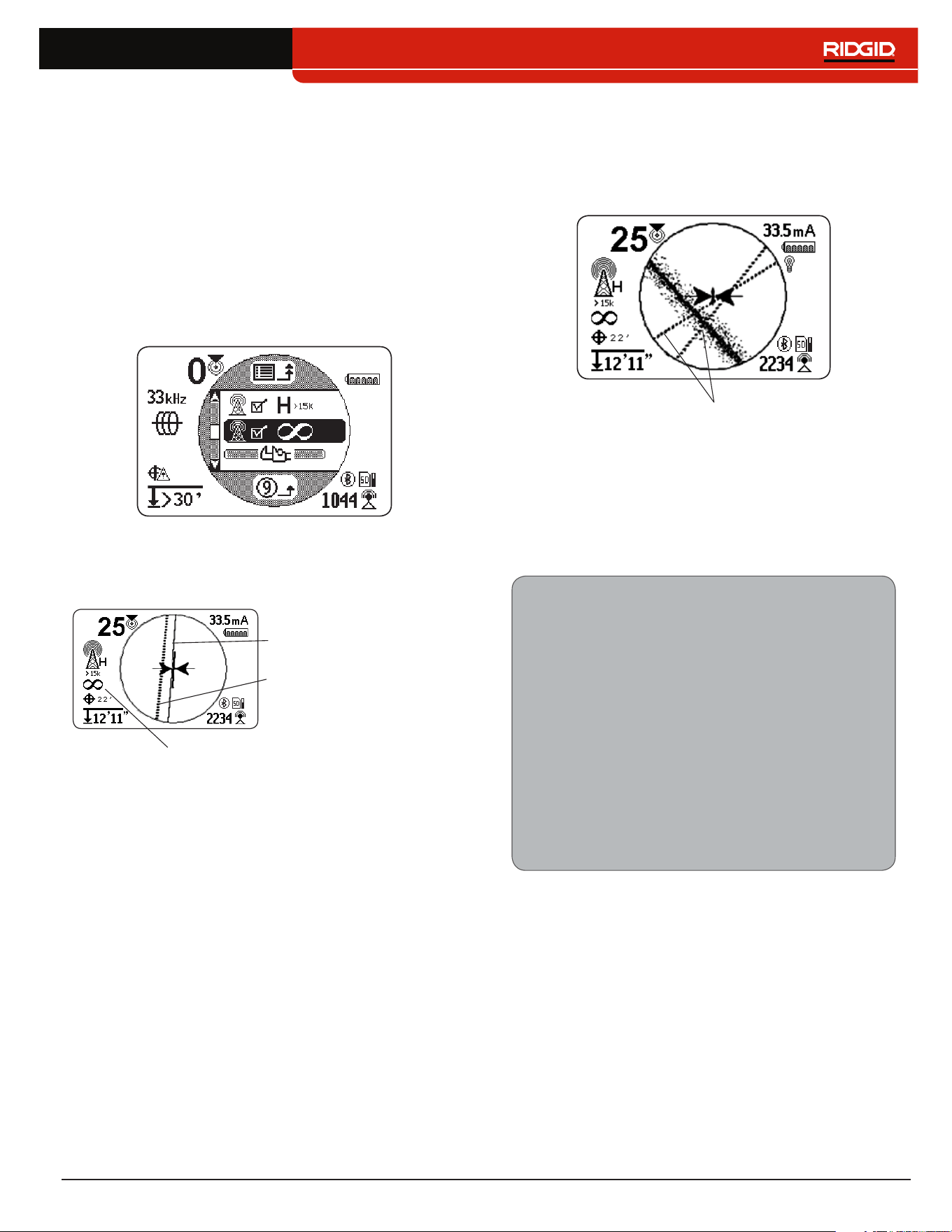
OmniSeek
OmniSeek passively traces the line by simultaneously
searching through the following three frequency bands:
• Less than 4 kHz
• From 4 kHz to 15 kHz
• Greater than 15 kHz
When OmniSeek is enabled, the SR‑24 searches for sig‑
nal energy in all three broadband ranges simultaneous‑
ly and displays a Tracing Line for each range that has a
usable signal�
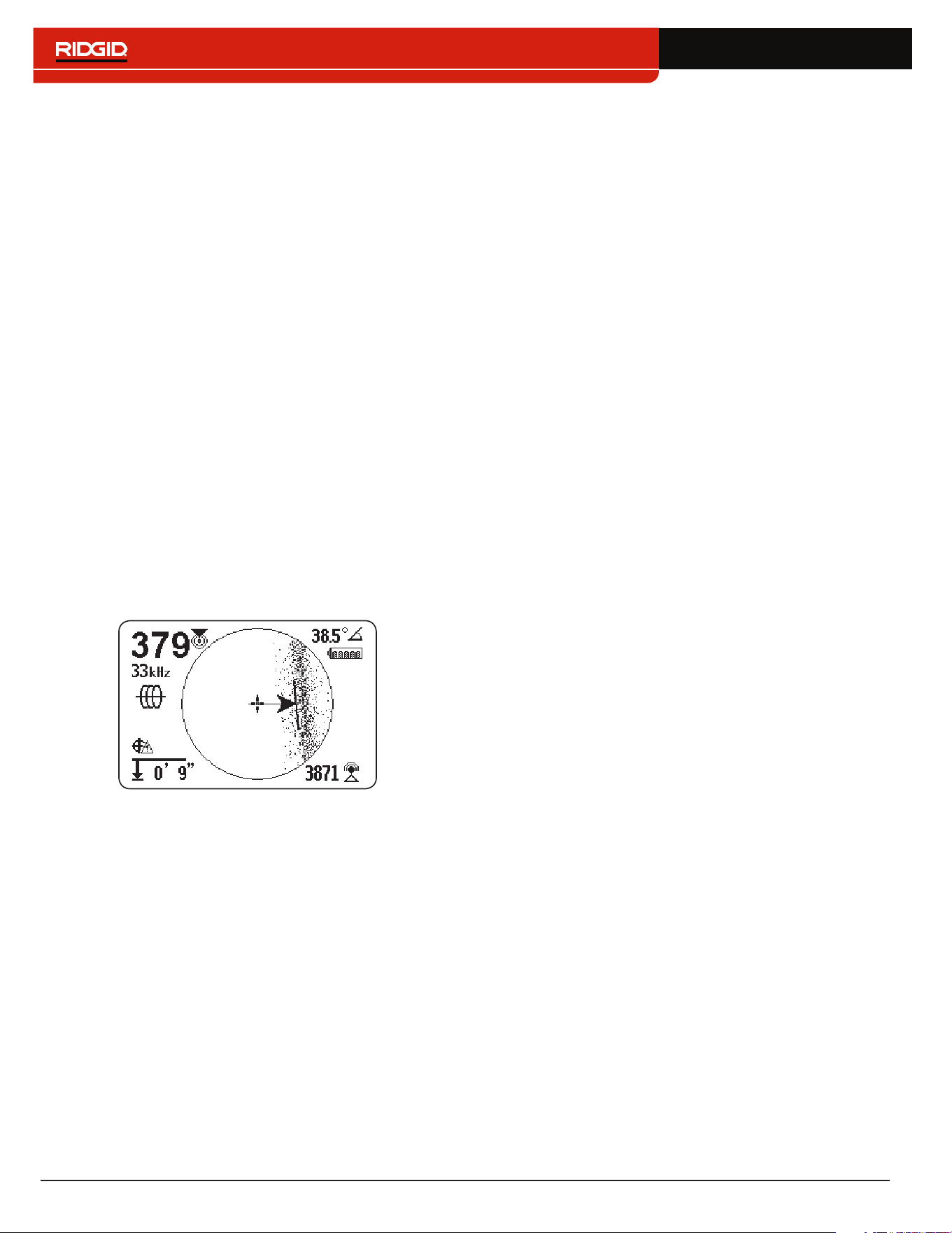
The signal that is closest to the receiver is the primary
signal and its frequency range is displayed above the
OmniSeek icon on the screen� The bold Tracing Line and
other display readings will reflect its characteristics�
Primary Tracing Line
OmniSeek Frequency Range
Secondary Tracing Line
If the SR‑24 detects signals in the other two frequency
ranges, it displays dashed Tracing Lines to indicate the
estimated position of these secondary signals� If the re‑
ceiver is moved, focus automatically shifts to the closest
signal�
Secondary Tracing Lines
Secondary Tracing Lines make it easier to detect the
presence of multiple utilities� If one or two Secondary
Tracing Lines appear out of alignment with the Tracing
Line, there may be another utility in the area� Secondary
Tracing Lines that are out of alignment could also indi‑
cate the presence of signal energy on the same utility in
different frequency bandwidths�
Conrming Accuracy
To confirm the accuracy of a locate, check that all of
the following are true:
• The Guidance Arrows and Guidance Line are
aligned with the Tracing Line�
• The Tracing Line shows little or no distortion�
• The Proximity Number and Signal Strength
maximize when the Tracing Line crosses the
map center�
• The measured depth increases appropriately
and the Tracing Line remains aligned when the
Depth Verification Test is performed�
Refer to the SR‑20 Instructional Video for a demonstra‑
tion of how to confirm accuracy of the locate and make
your locates accurate and efficient� The video is on a
DVD included with the SR‑24 manual pack or can be
viewed online:
www�RIDGID�com/us/en/instructional‑videos
24 – English
Sonde Locating
Sondes come in different shapes and sizes and are
often used to locate non‑con ductive pipes and conduits�
Some can be floated down a line and others can be at‑
tached to the end of a metal or fiberglass push cable�
Most SeeSnake
®
camera reels have a Sonde installed
inside or just be hind the camera head on the push cable�
The SR‑24 can locate the signal of a Sonde within a
pipe, allowing you to pinpoint the Sonde’s position and
depth underground�
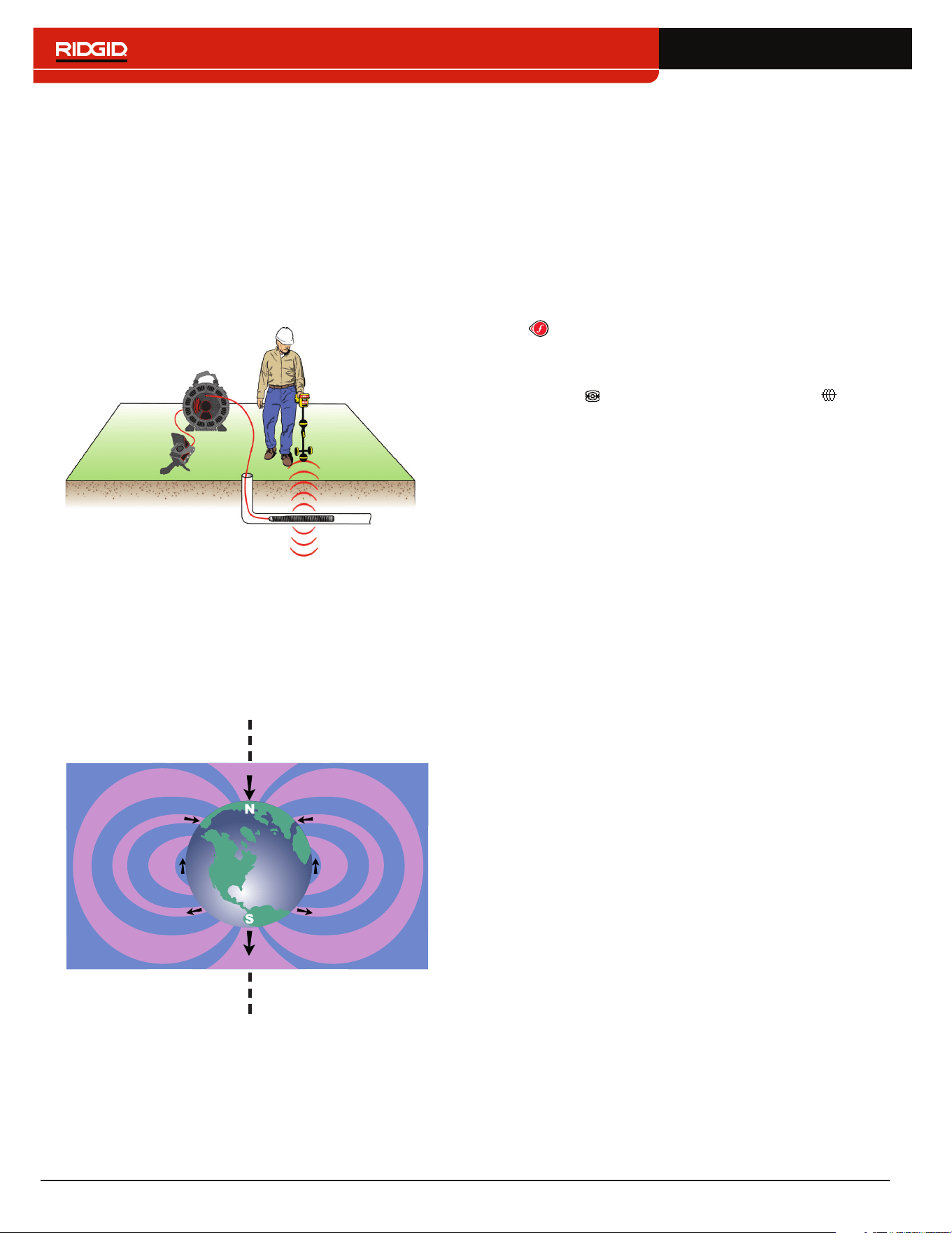
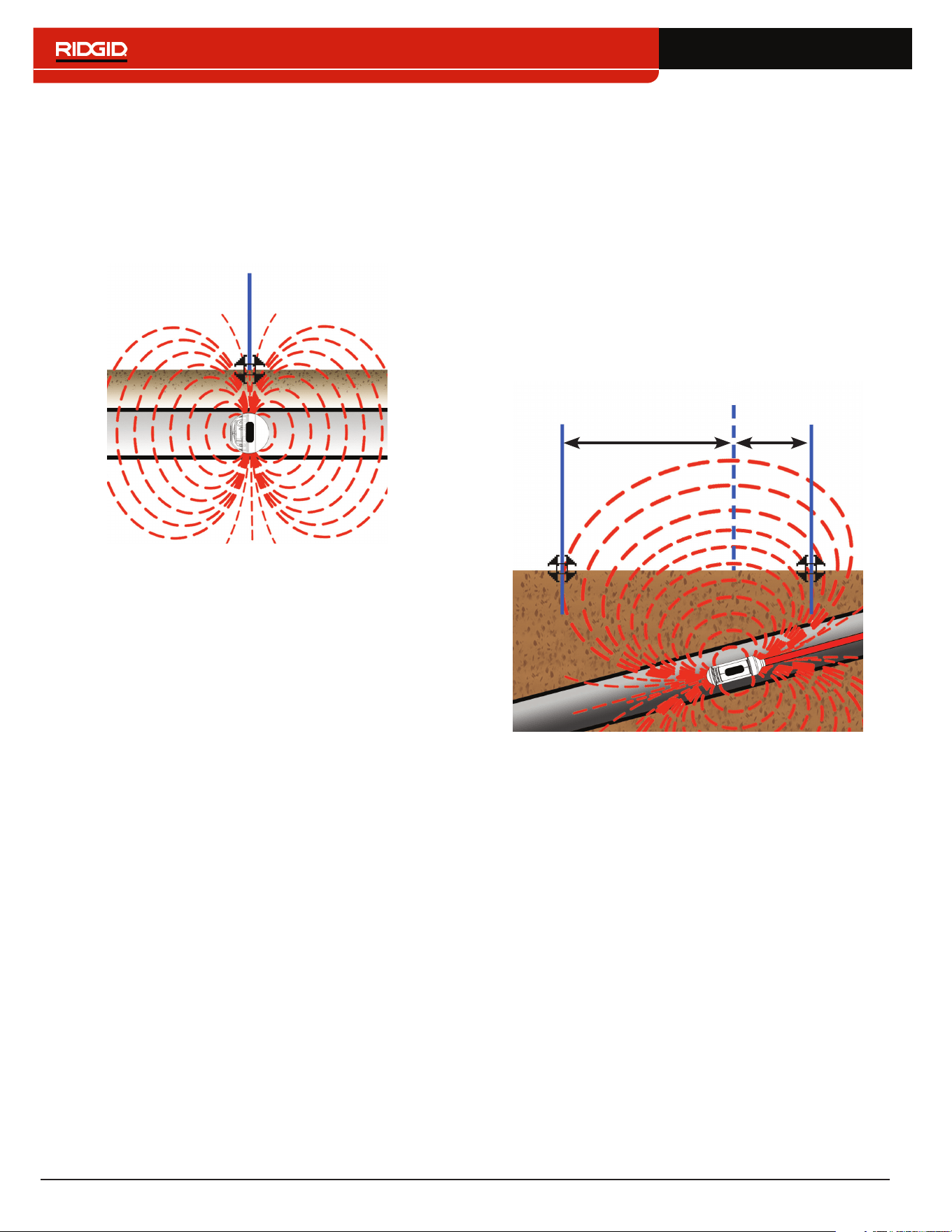
How the Sonde Works
When the Sonde is activated, a dipole field similar to the
dipole field around the Earth forms around the Sonde�
The SR‑24 detects the Sonde’s dipole field and uses the
field information to help the user locate the Sonde’s po‑
sition and depth�
Sonde Axis
Locating the Sonde
The primary means of locating the Sonde is by finding
the point where its signal is strongest� The SR‑24 also
has graphical icons that can be used to help find the
Sonde and map its position� Using the receiver’s graph‑
ical locating features can often speed up the locate and
reveal additional informa tion about the Sonde’s position
in the line�
To locate the Sonde, follow these steps:
1� Activate the Sonde and press the Frequency Key
on the SR‑24 to set it to the matching Sonde
frequency�
Note: Make sure you have selected a Sonde fre-
quency and not a Line Trace frequency .
2� Before putting the Sonde into the line, verify that it
is functioning properly and that the SR‑24’s Signal
Strength is registering a strong, steady signal�
3� Push the Sonde no more than 5m [15ft] into the
pipe�
You must be within range of the Sonde’s signal to
locate it� The range varies depending on the Sonde,
pipe material, depth, and soil composition�
4� To find the Sonde’s general direction, point the
SR‑24’s mast in the suspected direction of the
Sonde and sweep the horizon in a slow arc� The
Signal Strength is highest when the Lower Antenna
is closest to the Sonde and drops off when pointed
away in any other direction� The SR‑24’s sound may
be useful to find the highest Signal Strength�
5� Once you’ve detected the general direction of the
Sonde, lower the SR‑24 to its vertical operating
position and walk toward the Sonde� The Signal
Strength and audio tone increases as you move to‑
ward the Sonde and decreases as you pass its po‑
sition�
6� Continue searching for the highest signal by moving
the receiver left, right, forward and backward until
you have located the point where the signal is stron‑
gest and mark the Sonde’s position at this point�
English – 25
Using the SR-24’s Mapping Feature
The SR‑24’s mapping feature provides a fast, intui‑
tive way to find the Sonde’s position underground� The
Sonde’s dipole field is similar to the Earth’s magnetic
field, with two Poles and an Equator� The SR‑24 uses
icons to represent the position of the two Poles and the
Equator� Finding and marking the Poles and Equator can
give you a better picture of the Sonde’s position under‑
ground�
To map the location of the Sonde, follow these steps:
1� Follow steps 1 through 6 in the previous section�
2� Locate the first Pole�
As you approach the Sonde, either a Pole icon or
the Equator Line appears inside the Active View
Area� If you see the Equator Line first, move to the
left or the right until a Pole icon appears�
3� Center the Pole icon in the Cross Hairs and mark its
position with a red marker chip�
Note: The Pole’s location is most accurate when the
Lower Antenna is touching the ground and the re-
ceiver’s antenna mast is held vertical.
4� Locate the second Pole�
Move the receiver a few inches off the Pole until the
Pipe Direction appears� Two Sonde Equator icons
appear along the Equator Line once the first Pole
has been located, to indicate the Sonde’s location
is near�
Walk along the pipe in that direction� The second
Pole appears after you cross the Equator� Mark the
location of the second Pole with a red marker chip�
5� Locate the Sonde�
Move back toward the Equator� Align the receiver
between the two Poles, center the Equator on the
Cross Hairs, and mark the Sonde’s estimated loca‑
tion with a yellow marker chip�
Pole
Pole
Equator
6� To verify you have located the Sonde, make sure
the Signal Strength drops when you move the re‑
ceiver in any direction�
Note: Always verify your result by locating the point
where the Signal Strength is highest and marking
the Sonde at this location. If the sonde is horizon-
tal and not tilted, the equator will be at the point of
maximum signal strength.
26 – English
Floating Sondes
Sondes that are designed to be flushed or floated down
a pipe move freely and can ori ent any direction inside a
pipe� As a result, it may not be possible to accurately pin‑
point the Sonde by mapping the Poles and Equator� To
locate floating Sondes, find the point where the Signal
Strength is highest�
Pole
The RIDGID NaviTrack FloatSonde floats with the Pole
pointing straight up� Some other floating Sondes float
with the Sonde axis in line with the pipe� To locate a
Sonde in a vertical orientation, center the Pole icon in
the Active View Area� For vertical Sondes, only one pole
is found above ground�
Tilted Sondes
A Sonde is tilted when it is not parallel to the ground
above� This often happens when a Sonde is positioned
in a portion of pipe that is not horizontal� Mapping the po‑
sition of the Poles and Equator can help you determine
that a Sonde is tilted�
When a Sonde is tilted, the Equator will not be cen tered
between the two Poles� When a Sonde is severely tilt‑
ed, in a vertical portion of pipe, for example, the Equator
may not center over the Sonde and the point of maxi‑
mum Signal Strength may occur over a Pole� To locate
tilted Sondes, find the point where the Signal Strength
is highest�
Pole
Equator
Pole
A
B
English – 27
Depth
CAUTION
For the depth to display correctly, the mode must be
set correctly. Sonde frequencies and Line Trace fre-
quencies can sometimes be the same. Make sure the
mode icon next to the frequency that you are using,
is the mode you intend to be locating with.
The SR‑24 calculates measured depth by comparing the
difference in Signal Strength between the Upper Antenna
and the Lower Antenna� The measured depth indicator is
displayed in the lower left corner of the screen in either
meters or feet�
Note: Refer to the Units of Measurement section for in-
structions on how to change the depth units.
Depth Verication Test
To verify the SR‑24 is correctly measuring the target
line’s depth, follow these steps:
1� Touch the Lower Antenna to the ground directly
above the Sonde or the target line�
2� Vertically orient the antenna mast and note the
depth�
3� Raise the SR‑24 off the ground approximately
150mm [6in]�
4� Observe the change in measured depth� The mea‑
sured depth should increase by approximately
the same amount (in this example, approximately
150mm [6in])�
Note: An unchanging or drastically changing measured
depth may indicate the presence of a distorted field or a
line with very low current.
NOTICE
Use measured depths as estimates only.
Independently verify actual depths be-
fore excavating.
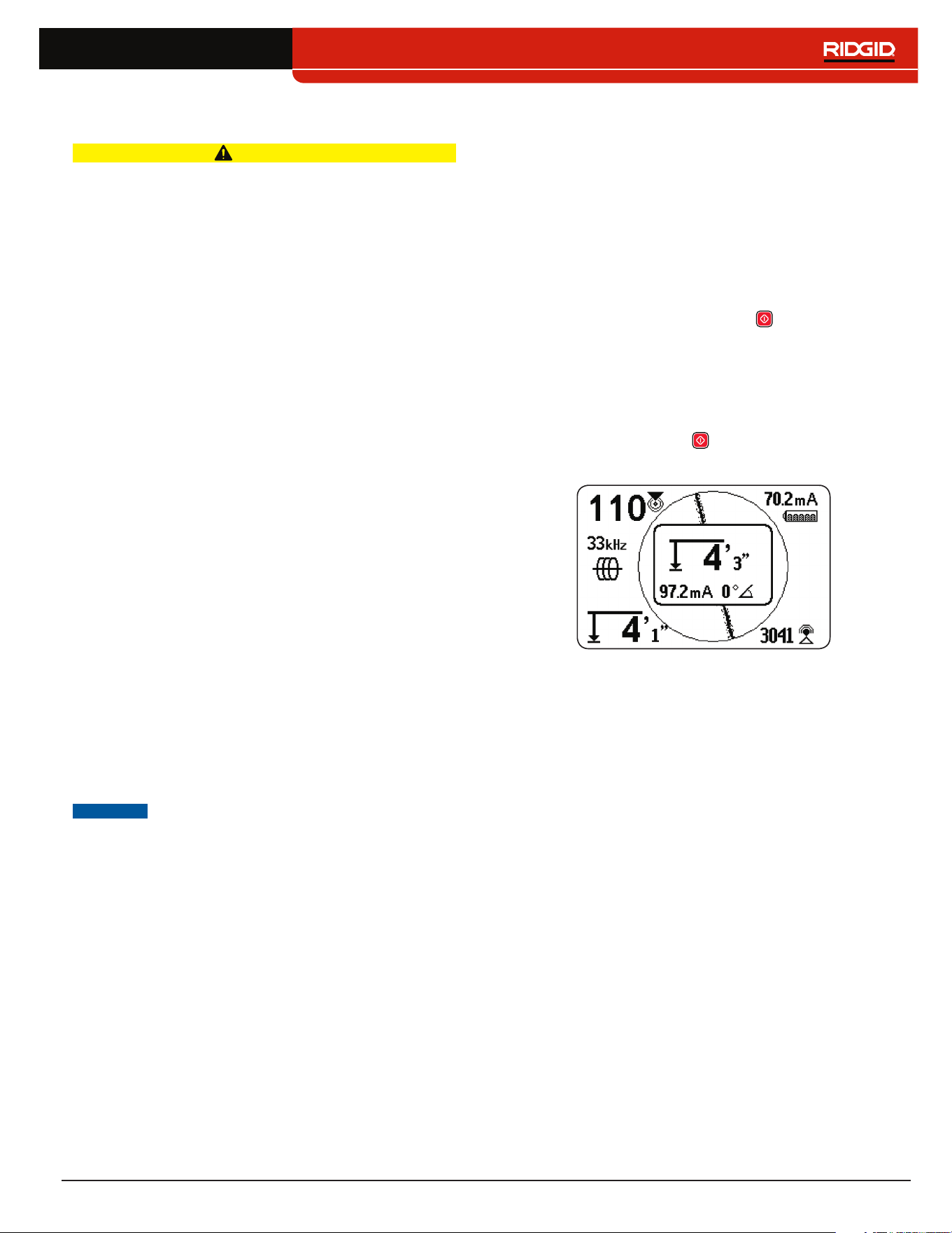
Depth Average
In addition to real‑time depth measurement, the Depth
Average feature is useful when the SR‑24 has variable
depth readings�
The Depth Average is a report that averages real‑time
depth readings from the past 2 to 6 seconds and dis‑
plays the average on screen inside the Active View Area
when prompted�
To create a Depth Average Report, follow these steps:
1� Press and hold the Select Key �
2� Wait for the countdown screen to go out of view and
for the SR‑24 to beep once�
3� The Depth Average Report shows the measured
depth, angle, and current of the target line�
4� Press the Select Key to exit and return to the re‑
al‑time depth reading�
28 – English
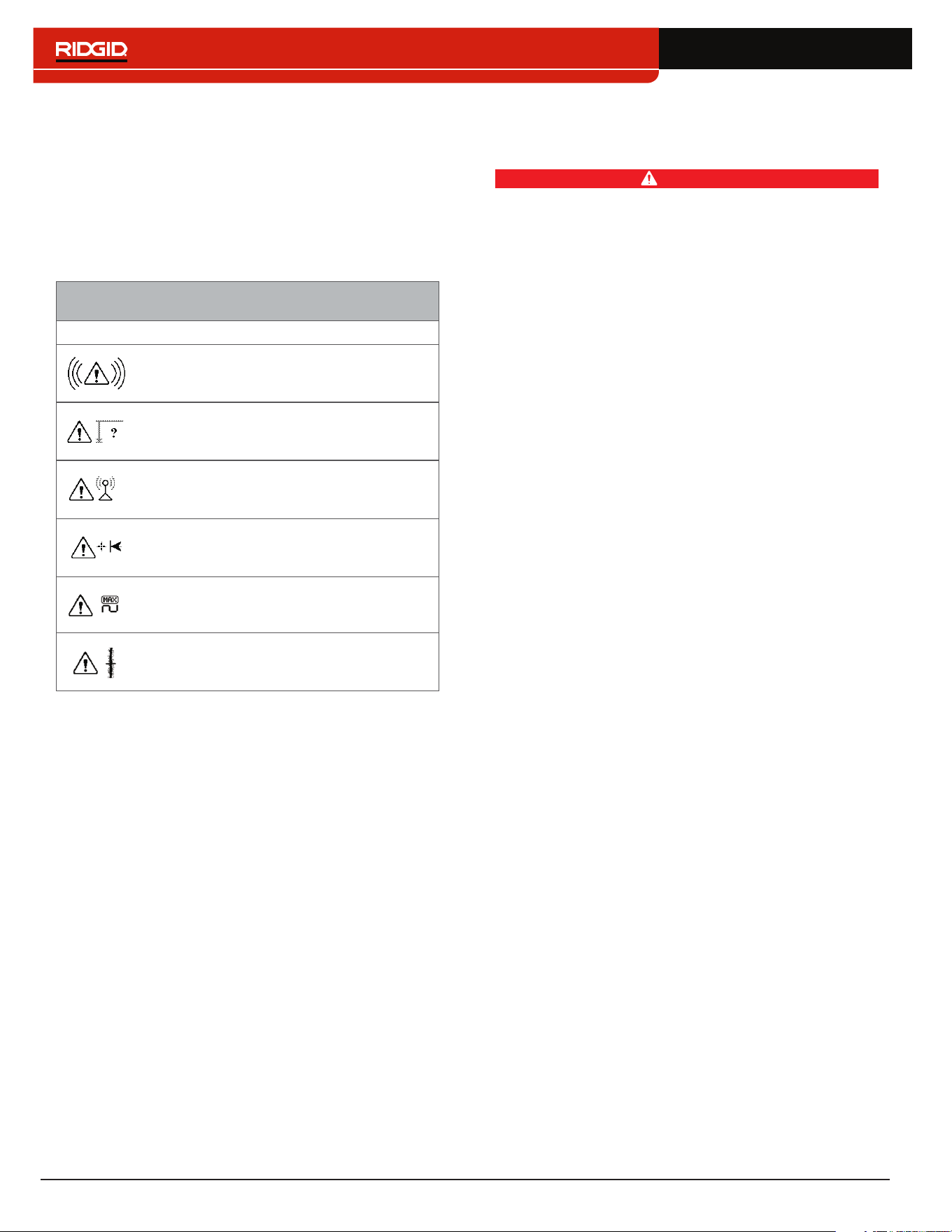
Depth Alerts
Under normal operating conditions, using Depth Average
can improve the accuracy of the locate by displaying av‑
eraged data� However, conditions such as distortion,
noisy environments, and clipping may affect accuracy�
A Depth Alert appears if conditions with the potential to
affect accuracy are encountered�
SR-24 Depth Alerts
Image Condition
Excessive motion during sampling
Depth varying significantly
Signal strength varying significantly
Extreme offset between Guidance Line
(right or left) and Tracing Line
Clipping (signal too high)
Too much distortion
Improving and Conrming
Accuracy
DANGER
Exposing the utility is the only way to be certain of
its location. If excavating a utility, periodically re-
check the measured depth and position to avoid
damaging the utility and to identify additional utility
signals that may have been overlooked.
Factors Affecting Accuracy
The following conditions can affect the accuracy of a lo‑
cate:
• Distortion due to local interference or poor signal
strength. Distortion is caused by the impact of nearby
fields, nearby conductors, magnetic flux, or other inter‑
ference on the circular electromagnetic field� Distortion
is detected by comparing the information from the
Tracing Line, Proximity Number, Signal Strength,
measured depth, Signal Angle readings, and Upper
Antenna measurements�
• Bleed over from the presence of other cables or
utilities. Bleed over happens when the signal from
the transmitter couples onto nearby non‑target lines�
The SR‑24 can receive the same frequency on multi‑
ple non‑target lines� Bleed over can distort fields and
illuminate unwanted utility lines� If possible, use lower
frequencies and eliminate connections between other
utilities�
• The presence of tees, turns, or splits in the line.
Turns or tees can cause a sudden increase in the
Tracing Line Distortion Response� If following a sig‑
nal that suddenly becomes distorted, circle the last lo‑
cation of a clear signal at a distance of approximately
6m [20ft]� Find the line nearby, to determine whether
or not the distortion is coming from a local turn or tee
in the line�
• Varying soil conditions. Very wet or very dry soil
can affect signal coupling� Saturating the soil with very
salty water may strengthen the circuit� Very dry soil
may weaken the circuit, if grounding is reduced�
• The presence of large, metal objects. The presence
of large, metal objects can cause unexpected increas‑
es or decreases in Signal Strength� This type of distor‑
tion appears stronger at higher frequencies�
• Low Signal Strength. If the signal is low, attempt to
improve the signal as specified in the following section�
English – 29
Signal Strength
If the Tracing Line cannot be centered or if it moves
across the screen erratically, the SR‑24 may not be re‑
ceiving a clear signal, stable measured depth, or a reli‑
able Proximity Number�
To attempt to improve the signal, do at least one of the
following:
• Check the transmitter and make sure that it is well
grounded�
• Check the tracing circuit’s Signal Strength by point‑
ing the Lower Antenna at one of the transmitter
leads� Improve the circuit if a weak signal is shown�
• Check that the SR‑24 and the transmitter are operat‑
ing on the same frequency�
• Switch to a higher frequency to overcome resistance
and to induce more current onto the line�
• Switch to a lower frequency to reduce bleed over�
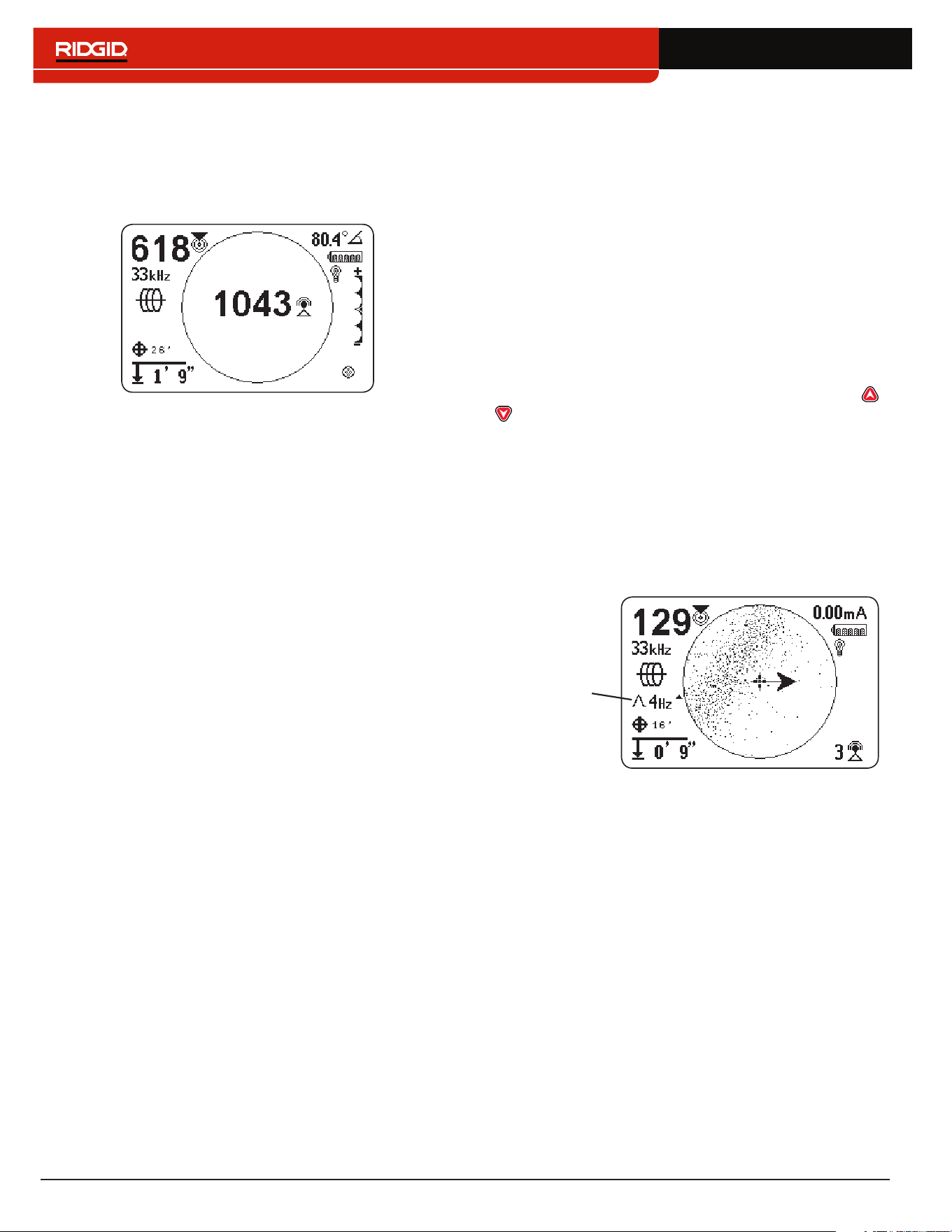
Clipping
Clipping occurs when the receiver cannot properly pro‑
cess the signal because the Signal Strength is too large�
Clipping occurs most often close to powerful sondes
and high current power lines� When clipping occurs, the
SR‑24 displays a warning symbol on the screen�
The SR‑24 responds to clipping by attenuating the mea‑
surement� Attenuation reduces the intensity of the Signal
Strength so the SR‑24 can measure it� If the SR‑24 is still
experiencing clipping, increase the distance between
the SR‑24 and the target line�
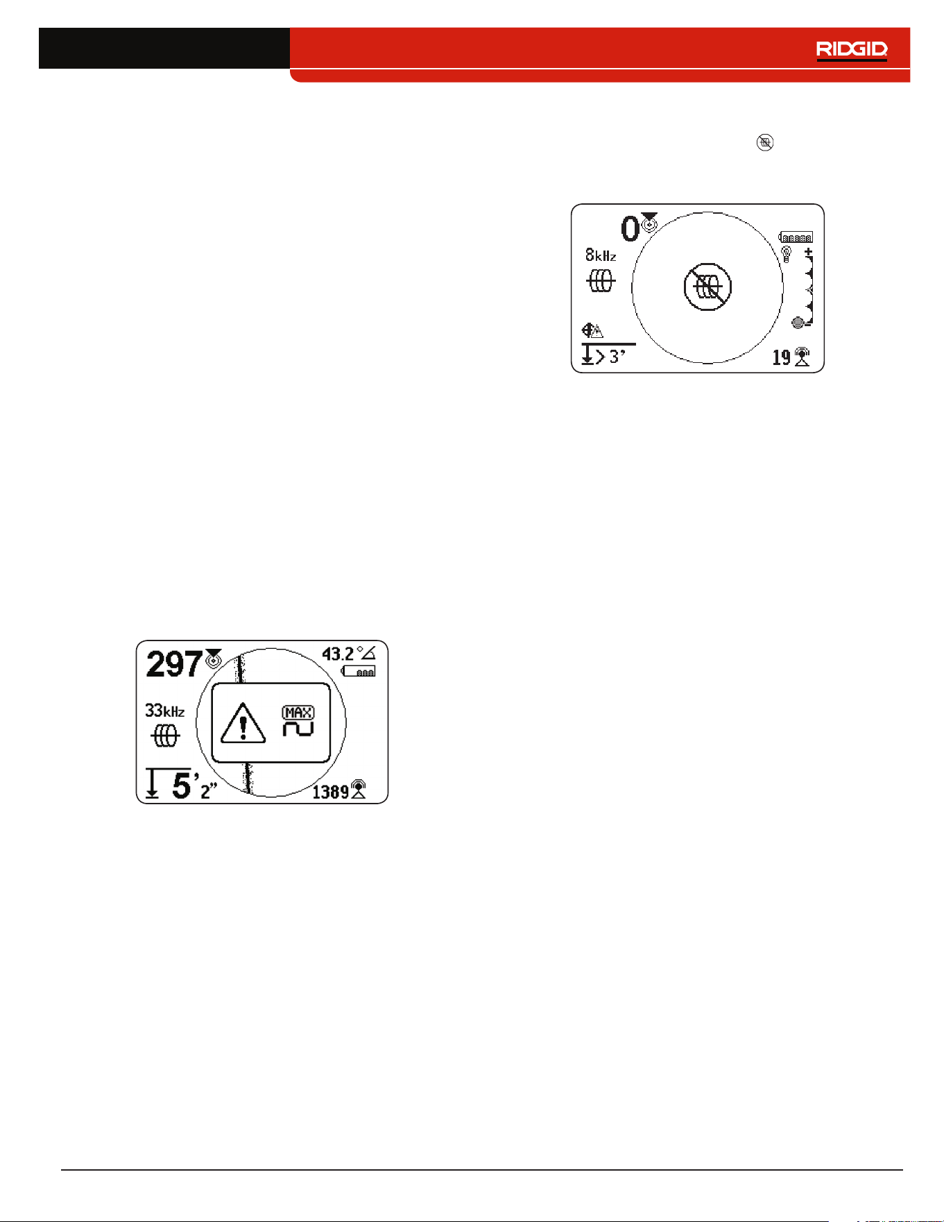
No Signal Icon
You can enable the No Signal icon to display when
there is no meaningful signal� The No Signal icon gives a
fast and easy notification that no signal is detected�
Note: The No Signal icon is disabled by default. Refer to
the Customizing Display Elements section for instruc-
tions on how to enable the No Signal icon.
If the No Signal icon appears, try the following to attempt
to gain a signal:
• Change the grounding
• Change the frequency
• Use induction
• Move the transmitter
30 – English
Center Signal Strength
Select the Center Signal Strength option to display the
Signal Strength in the center of the screen� The Center
Signal Strength option makes the Signal Strength easier
to see when locating using Signal Strength alone�
Note: The Center Signal Strength option is disabled by
default. Refer to the Customizing Display Elements sec-
tion for instructions on how to enable the Center Signal
Strength option.
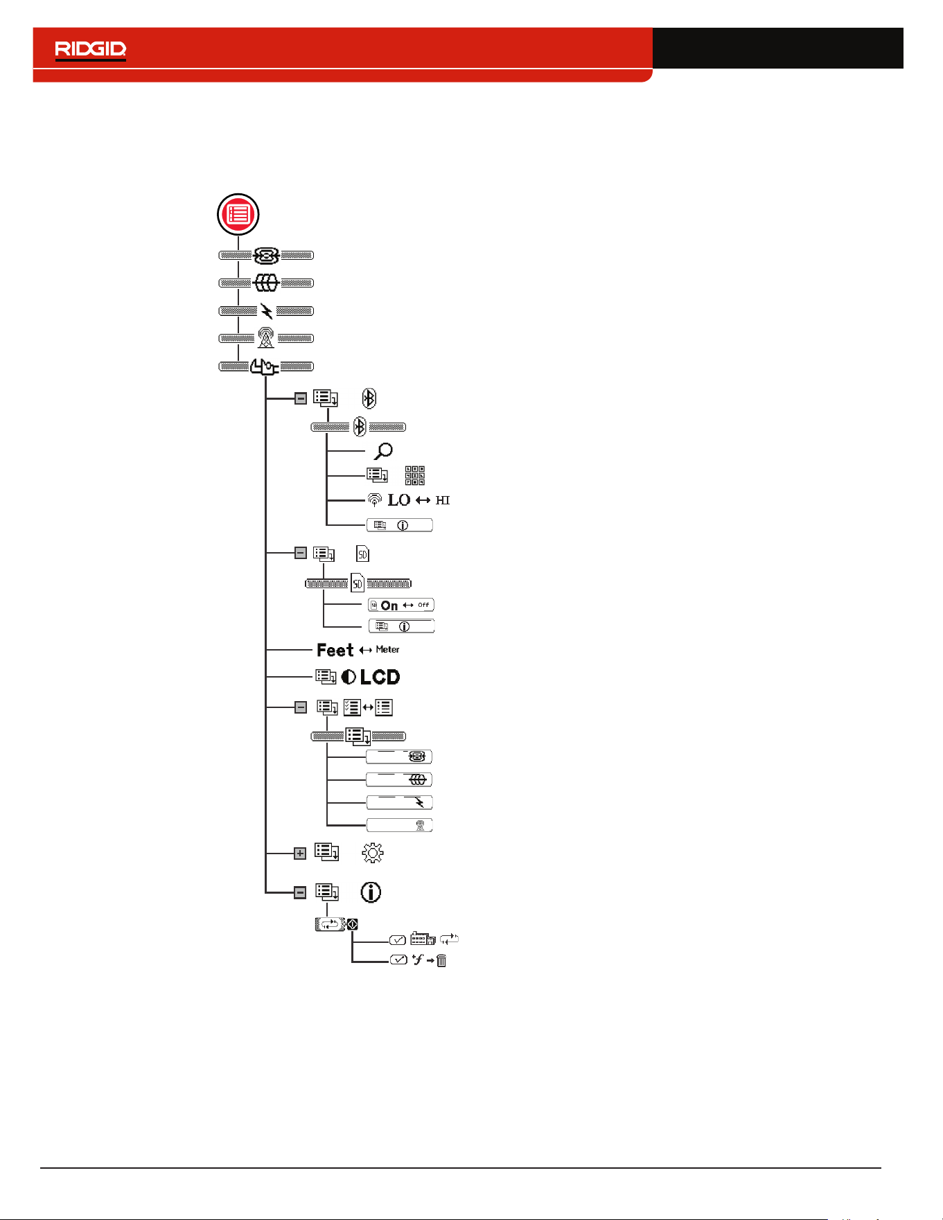
Signal Focus Control
Signal Focus Control acts as a magnifying glass on the
signal� It narrows the sample bandwidth and displays
more stable incoming signals, allowing the SR‑24 to
focus on a particular signal with increased detail�
Note: The selection of a narrow bandwidth increases the
detection distance and precision, but slows the refresh
rate of the display. As a result, when using the narrow-
est setting, move the SR-24 along the line more slowly.
The Signal Focus Control is disabled by default and must
be enabled in the Display Settings screen to make any
adjustments to it�
When the Signal Focus Control is activated, from the
Active View Area, use the Up and Down Arrow Keys
to set it to one of the following bandwidths:
• 4 Hz, wide (default setting when the Signal Focus
Control is disabled)
• 2 Hz
• 1 Hz
• 0�5 Hz
• 0�25 Hz, narrow
Signal Focus
Control
Note: The Signal Focus Control option is disabled by
default. Refer to the Customizing Display Elements sec-
tion for instructions on how to enable the Signal Focus
Control option.

English – 31
Tracing Circuit
A weak signal can often be improved by changing the
tracing circuit� To improve the circuit, perform one or
more of the following:
• Wet the soil around the ground stake�
• Move the ground stake away from the target line�
• Use a larger ground, such as a shovel blade�
• Ensure that the target line is not commonly bonded
to a utility� If bonded, undo the common bond, only
if it is safe to do so� Reconnect bonds, when locate
is complete�
• Change the frequency�
• Move the transmitter�
• Locate from the other direction along the line�
Conrming Accuracy
To confirm the accuracy of a locate, check that all of
the following are true:
• The Guidance Arrows and Guidance Line are
aligned with the Tracing Line�
• The Tracing Line shows little or no distortion�
• The Proximity Number and Signal Strength
maximize when the Tracing Line crosses the
map center�
• The measured depth increases appropriately
and the Tracing Line remains aligned when the
Depth Verification Test is performed�
Refer to the SR‑20 Instructional Video for a demonstra‑
tion of how to confirm accuracy of the locate and make
your locates accurate and efficient� The video is on a
DVD included with the SR‑24 manual pack or can be
viewed online:
www�RIDGID�com/us/en/instructional‑videos
Current Measurement (mA) and Signal Angle
The values displayed on the screen for Current
Measurement (mA) and Signal Angle are indicators
you can use to verify the accuracy of a locate� When
the Current Measurement (mA) is displayed and the
Guidance Arrows and Tracing Line are aligned, you can
be more confident your locate is accurate�
The SR‑24 detects the Current Measurement (mA) of
the target line and displays it in the upper right corner
of the screen� The Current Measurement (mA) is only
displayed when the SR‑24 is directly over the target
line� When the SR‑24 is not over the target line, the tar‑
get line’s Signal Angle displays instead of the Current
Measurement (mA)�
32 – English
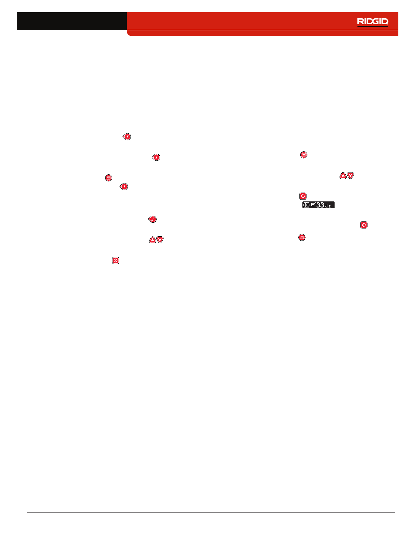
Main Menu
Below is a map of the top level Main Menu� The contents of the expanded Settings menu appear in the next section of
this manual�
SR-24
SR-24
SR-24
SR-24
Delete Custom Frequencies
Factory Reset
Bluetooth (SR-24 only)
Search for Devices
Bluetooth Pin
Bluetooth Power
Custom Frequencies
LCD Contrast
Units of Measurement
Sonde
Active Line Trace
Passive Power
Passive Radio + OmniSeek
Passive Power Frequencies
Active Line Trace Frequencies
Sonde Frequencies
Passive Radio Frequencies + OmniSeek
Information
Options
Bluetooth Information
Settings (see Settings section)
SD Card (SR-24 only)
Data Logging
SD Card Information
English – 33
Setting the Frequency
The instructions for selecting frequencies and activating
inactive frequencies from the Main Menu are the same
for Active Line Trace, Passive Power, Passive Radio
Frequency Broadband, OmniSeek, and Sonde frequen‑
cies�
Selecting Active Frequencies
There are three ways to change the frequency:
• Press the Frequency Key one or more times to
cycle through the list of active frequencies�
• Press and hold the Frequency Key to open the
Frequency Selection menu�
• Press the Menu Key , highlight the frequency, and
press the Frequency Key �
To change the Active Frequency through the Frequency
Selection menu, follow these steps:
1� Press and hold the Frequency Key for half a sec‑
ond to display a list of active frequencies�
2� Use the Up and Down Arrow Keys to highlight
the desired frequency�
3� Press the Select Key to set the highlighted fre‑
quency and return to active view�
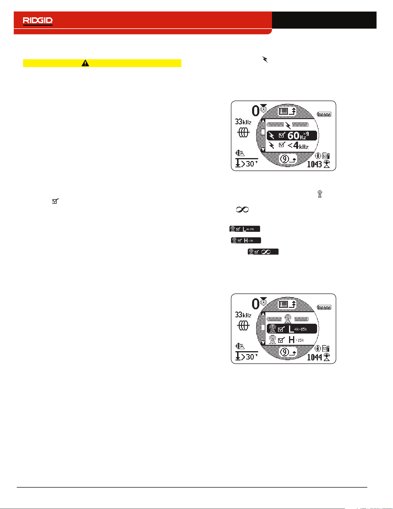
Activating Inactive Frequencies
Inactive frequencies are preprogrammed frequencies
that can be activated for specific uses� Inactive frequen‑
cies appear in the Main Menu with the box next to the
number unchecked�
When frequencies are activated they are added to the
Frequency Selection menu and appear in the Main Menu
with the box next to the number checked� Activate your
favorite frequencies to make frequency selection fast
and easy�
To activate inactive frequencies, follow these steps:
1� Press the Menu Key to see the complete list of
available frequencies�
2� Use the Up and Down Arrow Keys to highlight
the desired inactive frequency�
3� Press the Select Key to check the box next to the
highlighted frequency �
To deactivate frequencies, uncheck the box next to
the frequency by pressing the Select Key �
4� Press the Menu Key to save and exit�
34 – English
Bluetooth
The following section applies to the SR-24 only.
The SR‑24 is compatible with Bluetooth 2�0 devices that
use the RFCOMM profile, including many smart phones,
tablets, and GPS units� Refer to www�RIDGID�com/SR24
for a list of some models that have been tested to work
with the SR‑24�
You can connect the SR‑24 to compatible Bluetooth
devices and configure connection options from the
Bluetooth Options menu�
Bluetooth Connection Method
To use Bluetooth you must connect the SR‑24 and
your Bluetooth device� To initiate connection from your
Bluetooth device, follow these steps:
1� Enable Bluetooth on your Bluetooth device�
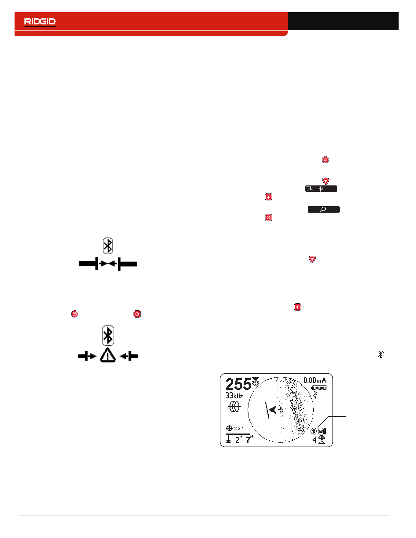
2� Open the Bluetooth list and select the SR‑24 from
the list� After connecting, the SR‑24 briefly displays
the following image on screen�
3� Make sure the status of the SR‑24 on your device’s
Bluetooth list appears as connected� The SR‑24 has
failed to connect when the image below displays on
the SR‑24’s screen� The image displays until the
Menu Key or the Select Key is pressed�
Note: If there is a Bluetooth device present and the
SR-24 has failed to connect, repeat step 2.
4� Once connected, confirm the Bluetooth icon ap‑
pears in the bottom right of the SR‑24’s screen�
Alternate Bluetooth Connection Method
Note: It is usually most convenient to initiate the Bluetooth
connection to the SR-24 from the Bluetooth device.
If you are unable to initiate the connection from your
Bluetooth device try the alternate method from the
SR‑24� To initiate the Bluetooth connection from the
SR‑24’s Main Menu, follow these steps:
1� Make sure your Bluetooth device is enabled and
discoverable�
Note: The Bluetooth device must be discoverable
for the SR-24 to find it.
2� Press the SR‑24’s Menu Key to open the Main
Menu�
3� Use the Down Arrow Key to highlight the
Bluetooth Options icon and press the
Select Key to open the Bluetooth Options menu�
4� Highlight the Search icon and press the
Select Key to search for Bluetooth devices�
Note: If there is a Bluetooth device present and the
SR-24 has failed to find the Bluetooth device, make
sure the Bluetooth device is discoverable.
5� Use the Down Arrow Key to highlight the device
you want to connect to�
Note: New Bluetooth devices appear below the
previously paired devices in the Bluetooth Options
menu.
6� Press the Select Key to connect the SR‑24 to the
Bluetooth device�
Confirming Bluetooth Connection
During operation, confirm your Bluetooth device is con‑
nected to the SR‑24 by observing the Bluetooth icon
in the bottom right of the screen�
Bluetooth
enabled
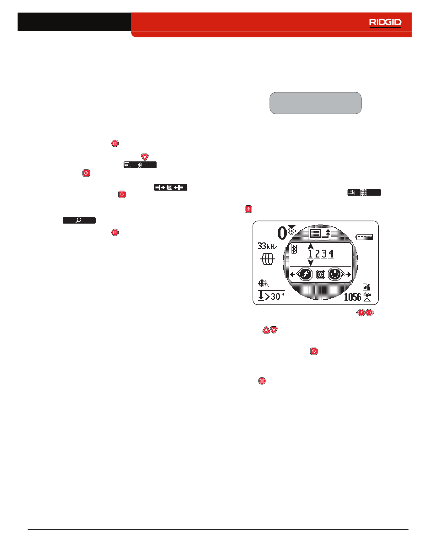
English – 35
Disconnecting Bluetooth
There are two ways to disconnect the SR‑24 and your
Bluetooth device� Disconnect Bluetooth from your
Bluetooth device or from the SR‑24’s Main Menu�
Note: Refer to your Bluetooth device for information on
how to disconnect a Bluetooth connection from your
Bluetooth device.
To disconnect the SR‑24 and your Bluetooth device from
the SR‑24’s Main Menu, follow these steps:
1� Press the Menu Key to open the Main Menu�
2� Use the Down Arrow Key to highlight the
Bluetooth Options icon and press the
Select Key to open the Bluetooth Options menu�
3� Highlight the Disconnect icon and
press the Select Key to disconnect the SR‑24
and your Bluetooth device� When disconnected,
the Disconnect icon will change back to the Search
icon �
4� Press the Menu Key to exit�
Note: To make changes to the Pin, Bluetooth Power, or to
view the Bluetooth Information screen, you must first dis-
connect the Bluetooth.
Bluetooth Pin
Some Bluetooth devices require a pin to connect to the
SR‑24� If a pin is necessary, enter the SR‑24’s pin into
your Bluetooth device�
The default pin is 1234.
If desired, you can change the SR‑24’s Bluetooth pin
on the SR‑24� To change the SR‑24’s pin, follow these
steps:
1� Disconnect the SR‑24 and your Bluetooth device�
Note: Refer to the previous section for instruc-
tions on how to disconnect the SR-24 and your
Bluetooth device.
2� Highlight the Bluetooth Pin icon in the
Bluetooth Options menu and press the Select Key
to open the Bluetooth Pin screen�
3� Use the Left and Right Arrow Keys to move
between digits and use the Up and Down Arrow
Keys to increase and decrease the value of
the digits�
4� Press the Select Key to save the pin and exit the
Bluetooth Pin screen�
5� To abort any changes to the pin, press the Menu
Key to return to the Bluetooth Options menu�
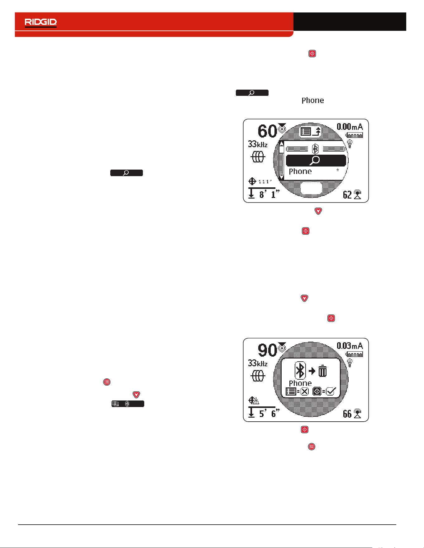
36 – English
Bluetooth Auto-Connect
After connecting for the first time, the SR‑24 no longer
requires a pin to connect to that Bluetooth device� When
the SR‑24 is powered on, it automatically searches for
any device that has previously connected to� The SR‑24
automatically connects if it is within range of a previously
connected device and the device is available�
Note: The device does not need to be discoverable to
reconnect to the SR-24.
The SR‑24 can save up to sixteen Bluetooth devic‑
es� When maximum capacity is reached and a new
Bluetooth device is added, the SR‑24 replaces an old
Bluetooth device with the new Bluetooth device in the
list below the Search icon in the Bluetooth
Options menu�
The SR‑24 continues to attempt to auto‑connect if you
disconnect the Bluetooth connection from your Bluetooth
device� To disconnect an automatically connected de‑
vice from the SR‑24 you must do so from the SR‑24’s
Bluetooth menu� Refer to the Disconnecting Bluetooth
section for instructions on how to disconnect Bluetooth�
Once you have disconnected an auto‑connected de‑
vice from the SR‑24, no further automatic connection
attempts will be made for the remainder of that power
cycle� When the SR‑24 is powered off and then powered
on, the Bluetooth reinstates its default setting and at‑
tempts to auto‑connect to any previously connected de‑
vice within range�
The SR‑24 searches for all previously connected devic‑
es within range� The SR‑24 connects to the previously
connected device that is available� If more than one pre‑
viously connected device is in range and available, the
SR‑24 attempts to connect to one, beginning at the top of
the list, and going down the list until connected�
If you want to connect to a device that the SR‑24 did not
automatically connect to, follow these steps:
1� Press the Menu Key to open the Main Menu�
2� Use the Down Arrow Key to highlight the
Bluetooth Options icon �
3� Press the Select Key to open the Bluetooth
Options menu�
The name of the previously connected device ap‑
pears with an asterisk below the Search icon
in the Bluetooth Options menu� The fol‑
lowing image shows as a device that has
previously been connected to the SR‑24�
4� Use the Down Arrow Key to highlight the device
you want to connect to�
5� Press the Select Key to connect the SR‑24 to a
specific device that has previously been connect‑
ed to�
If you are no longer using a Bluetooth device, you can
remove it from the list of previously connected devices,
follow these steps:
1� Open the list of previously connected devices� Use
the Down Arrow Key to highlight the device you
want to remove from the list�
2� Press and hold the Select Key for about one sec‑
ond�
3� Press the Select Key to delete the Bluetooth de‑
vice from the list of previously connected devices
or press the Menu Key to return to the previous
screen�
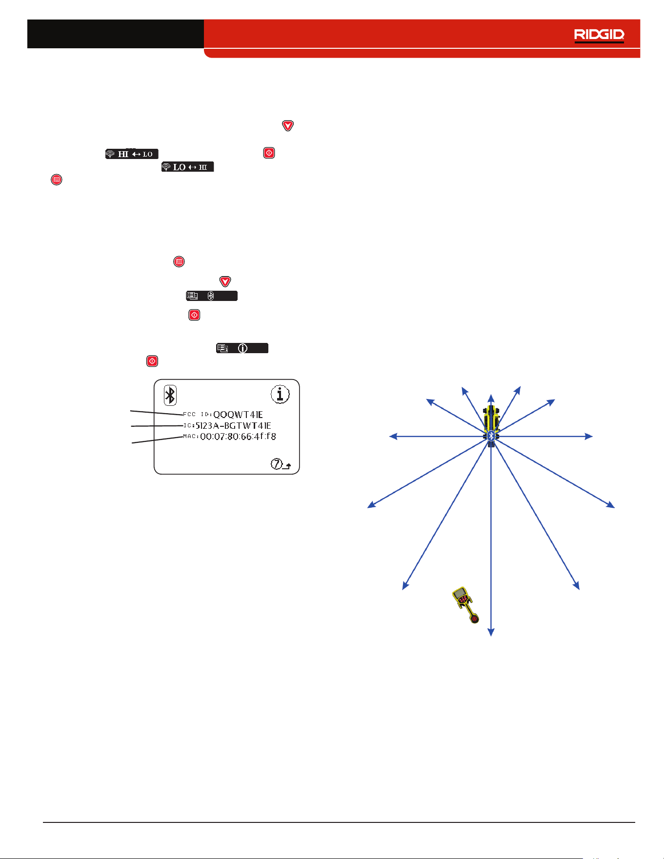
English – 37
Bluetooth Power Settings
To change the Bluetooth power settings from high (de‑
fault) to low, you must disconnect the SR‑24 and the
Bluetooth device� Then use the Down Arrow Key from
the Bluetooth Options menu to highlight the Bluetooth
Power icon � Press the Select Key to toggle
between high and low � Press the Menu Key
to save and exit�
Bluetooth Information
To view the Bluetooth Information screen, follow these
steps:
1� Press the Menu Key to open the Main Menu�
2� Use the Down Arrow Key to highlight the
Bluetooth Options icon �
3� Press the Select Key to open the Bluetooth
Options menu�
4� Highlight the Information icon and press
the Select Key �
FCC ID
IC
MAC
Connecting to a Transmitter with
Bluetooth
The following section applies to the SR-24 only.
With Bluetooth enabled, the SR‑24 can be used to view
and control the transmitter’s screen, eliminating the need
to walk back and forth between your transmitter and the
area being traced� Use the SR‑24 to remotely set fre‑
quencies, output power, turn the transmitter on and off,
or know if the transmitter has turned off unexpectedly�
Range
The ST‑33Q+ and SR‑24 work best when kept with‑
in 200 m [656 ft] of each other while connected by
Bluetooth� The quality of the connection between devic‑
es may be affected by a number of factors including dis‑
tance between devices and objects in the path between
devices� For the best quality connection, maintain a clear
line of sight between devices and set the transmitter so
its battery faces the receiver� Objects blocking the line of
sight between the transmitter and the receiver may sig‑
nificantly reduce the quality of their connection�
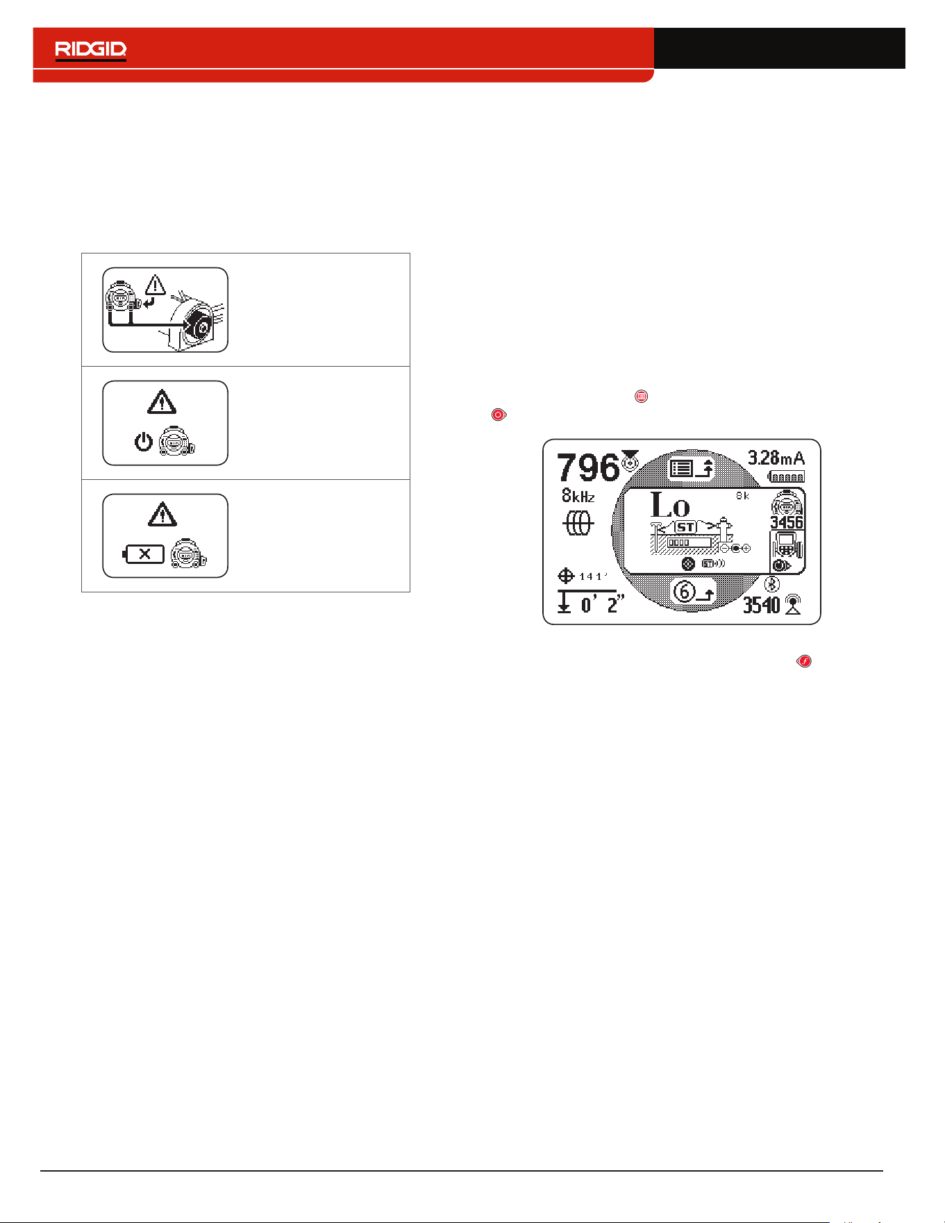
38 – English
Powering the Transmitter
When the two units are connected with Bluetooth, pow‑
ering the receiver on or off automatically powers the
transmitter on or off�
The receiver alerts you to changes in the transmitter’s
power status�
Switching to internal
batteries�
Powered off due to
Power Key press�
Powered off due to
low battery�
Setting the Frequency
Changing the receiver’s frequency automatically updates
the transmitter’s frequency to match� If the frequency is
changed on the transmitter, the receiver automatically
updates to match as well�
Transmitter Control Screen
The following section applies to the SR-24 only.
When the devices are connected, you can see the trans‑
mitter’s screen from the receiver� The transmitter control
screen allows you to control the transmitter’s frequen‑
cy mode, choose between direct connect or inductive
mode, and adjust output power remotely� You can also
remotely power the transmitter on or off and know if the
transmitter has powered off unexpectedly�
Any changes made on the transmitter to frequency, di‑
rect connect or inductive mode, and output power can be
seen on the receiver�
To open the transmitter control screen on the receiver,
press the Menu Key , then press the Right Arrow Key
to toggle in and out of the transmitter’s control screen�
If more than one Bluetooth enabled SeekTech trans‑
mitter is present, press the Left Arrow Key to cycle
through available transmitters� Press the serial number
listed below the transmitter icon to identify the specific
transmitter you want to control�
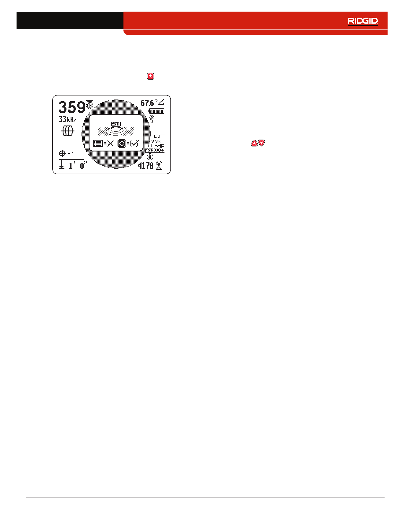
English – 39
Direct Connect Mode and Inductive Mode
To remotely set the transmitter to direct connect mode
or inductive mode using the receiver, open the transmit‑
ter control screen� Press the Select Key to toggle be‑
tween direct connect mode and inductive mode�
Clamp Mode
The receiver can see the transmitter’s clamp mode but
cannot turn the transmitter’s clamp mode on or off� An
inductive clamp must be connected to access clamp
mode� Refer to the operator’s manual for your transmitter
and inductive clamp for more information on using induc‑
tive clamp mode�
Output Power
Higher output settings produce a stronger signal for
the receiver, but reduces battery life for the transmitter�
Only use 1,000 mA High Output Mode if using an 18V
Lithium‑ion rechargeable battery, external power, or high
capacity NiMH D cell batteries� Do not use the ST‑33Q+
in high output mode with standard alkaline batteries�
You can read the transmitter’s output power or change it
remotely from the receiver� To remotely change the trans‑
mitter’s output power using the receiver, open the trans‑
mitter control screen� Press the receiver’s Up and Down
Arrow Keys to adjust the output power�
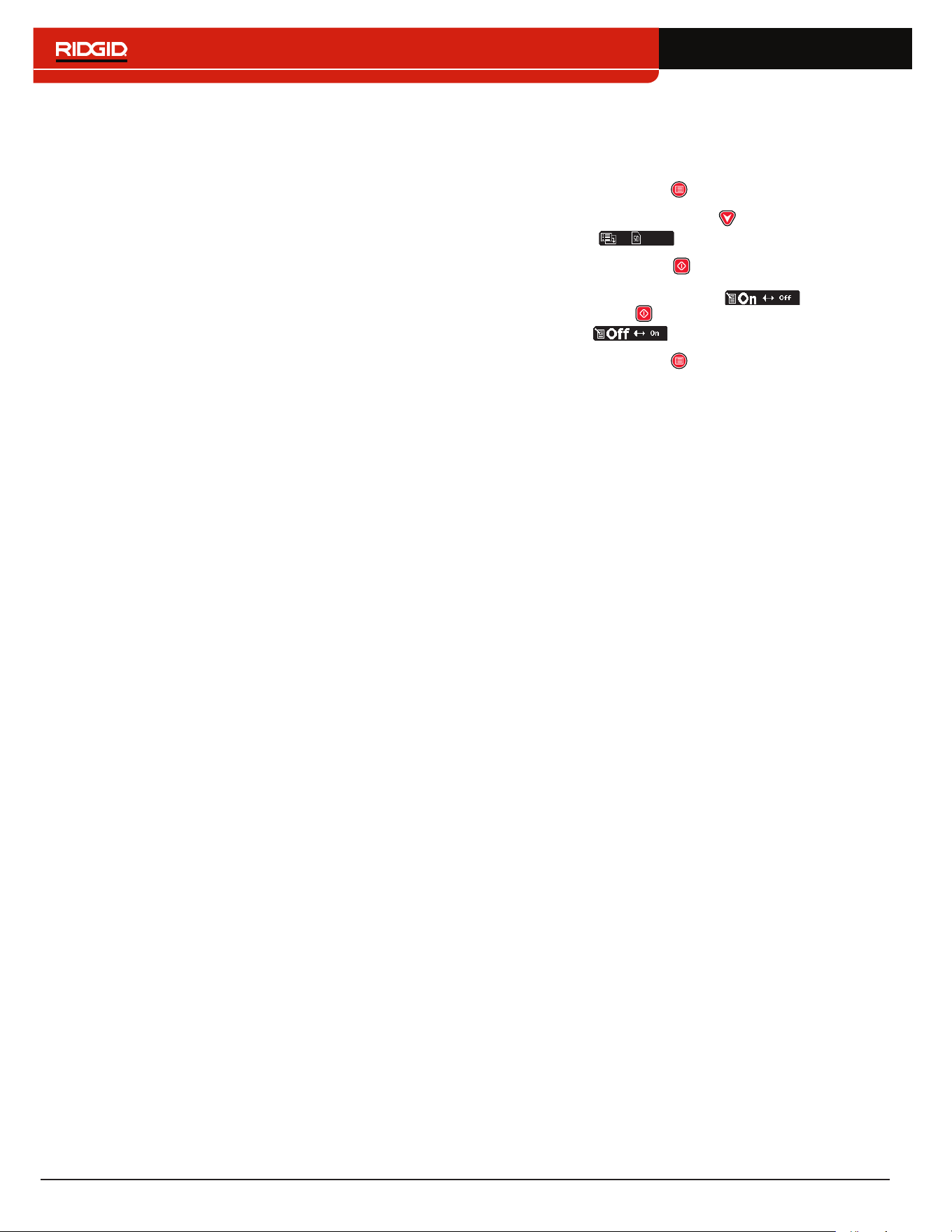
40 – English
SD Card
The following section applies to the SR-24 only.
The Data Output feature sends the SR‑24’s locate data
to the internal SD card, or to a Bluetooth device if one
is available, or to both simultaneously� Full data logging
is enabled by default, and you can disable an entire
category or specific elements within a category� Refer
to Appendix C for descriptions of the data logging ele‑
ments�
Note: Refer to the Data Output section for instructions
on how to disable and enable entire categories or spe-
cific elements within a category.
Data can be logged continuously (default), or manual‑
ly at specific points during a locate, by enabling User‑
Initiated Data Output� When User Initiated Data Output is
enabled, continuous data logging is turned off, resulting
in a log file that contains only the information you want�
Data Logging
To disable data logging from the SD Card menu, follow
these steps:
1� Press the Menu Key to open the Main Menu�
2� Use the Down Arrow Key to highlight the SD
Card icon �
3� Press the Select Key to open the SD Card menu�
4� Highlight the Logging icon and press
the Select Key to toggle between “On” (default)
and “Off” �
5� Press the Menu Key to save and exit�
Note: The SR-24 is compatible with Bluetooth 2.0 devic-
es including many phones, tablets, and GPS units. Refer
to www.RIDGID.com/SR24 for a list some models that
have been tested to work with the SR-24.
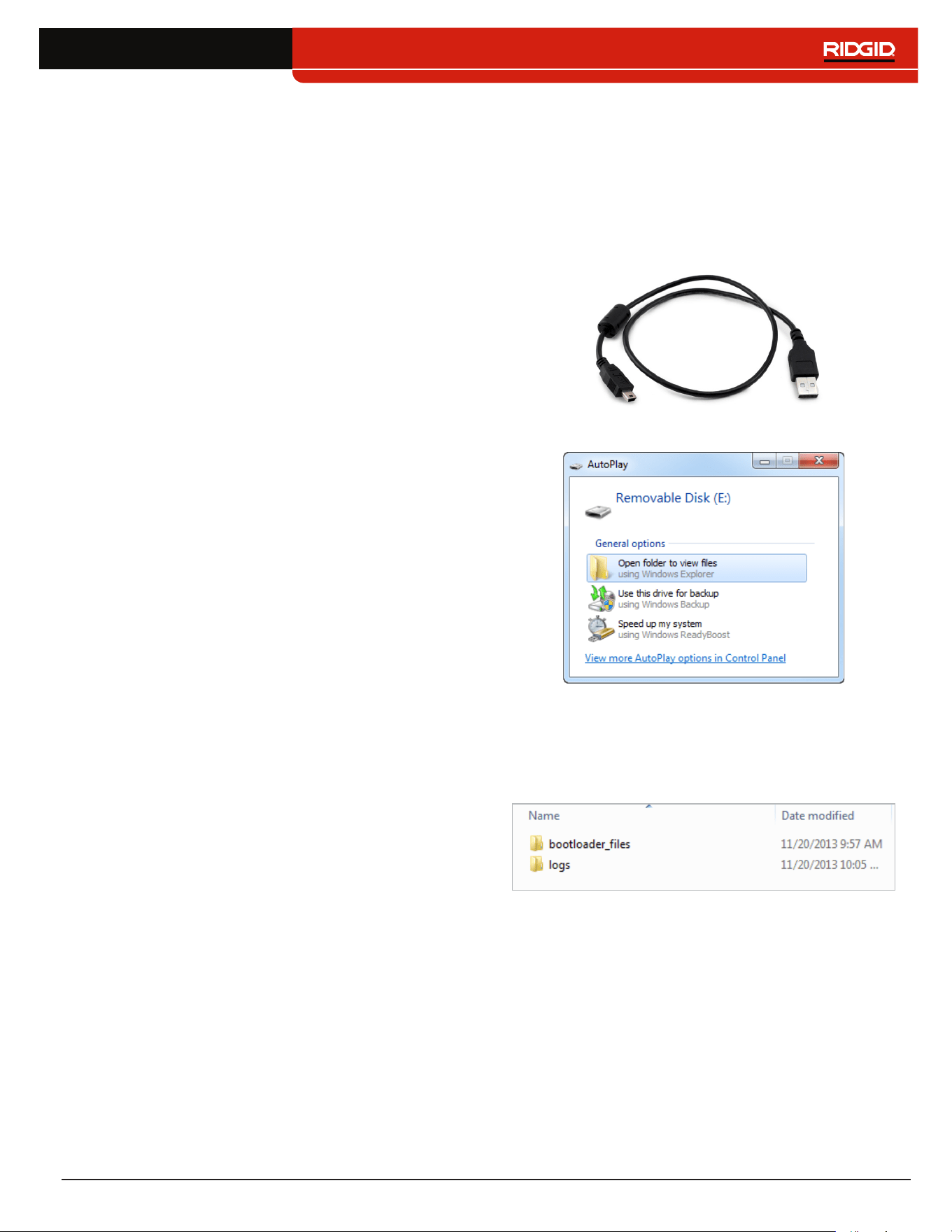
English – 41
Data Log Files
During continuous streaming (logging is enabled), GPS
data is sent once per second and SIG and LCD data is
sent twice per second� Data is logged on your Bluetooth
device and the internal SD card at the same time�
The internal SD card acts as a USB drive and stores
data that can be exported� If logging is enabled for all
data, the SD card’s capacity fills up at a rate of 3MB per
hour� The included 16GB SD card will take 5,461 hours
to fill capacity�
Note: Ridge Tool Company and its affiliates reserve the
right to change the specifications of the hardware, soft-
ware, or both as described in this manual without notice.
Refer to www.RIDGID.com/SR24 for current updates
and supplemental information pertaining to this product.
Data logged on the internal SD card is saved in a �txt for‑
mat file� To export data log files from the SD card, follow
these steps:
1� Connect the SR‑24 to a computer with a mini‑B
USB cable�
Note: The SR-24 does not need to be powered on
to transfer files.
2� Open the folder to view files when prompted�
3� There are three folders stored on the SD card� Open
the folder named “logs�”
Note: The folders named “bootloader_files” and
“gps_binary_logs” are not used during normal op-
eration.
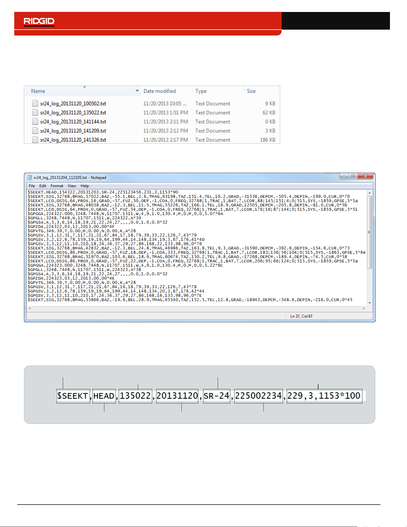
42 – English
4� Data log files in the “logs” folder are named according to the date and time they were created, for example: sr24_log_
yyyymmdd_HHMMSS�txt�
If data logging is enabled, a new file is created when the SR‑24 is powered on� The log file closes when the SR‑24
is powered off�
5� Open the desired data log file� The data log file should automatically open in Notepad or your default text editor� In the
data log file, the first line is the header and the lines that follow contain the logged data�
Understanding the Data Log File
The first line of the data log file is the file’s header and it contains the SeekTech String Identifier, Header Identifier, Time
(HHMMSS), Date (yyyymmdd), Receiver Name, Serial Number, and Processor Versions�
DateHeader Identifier
Time
SeekTech String Identifier
Receiver Name
Serial Number
Software Versions
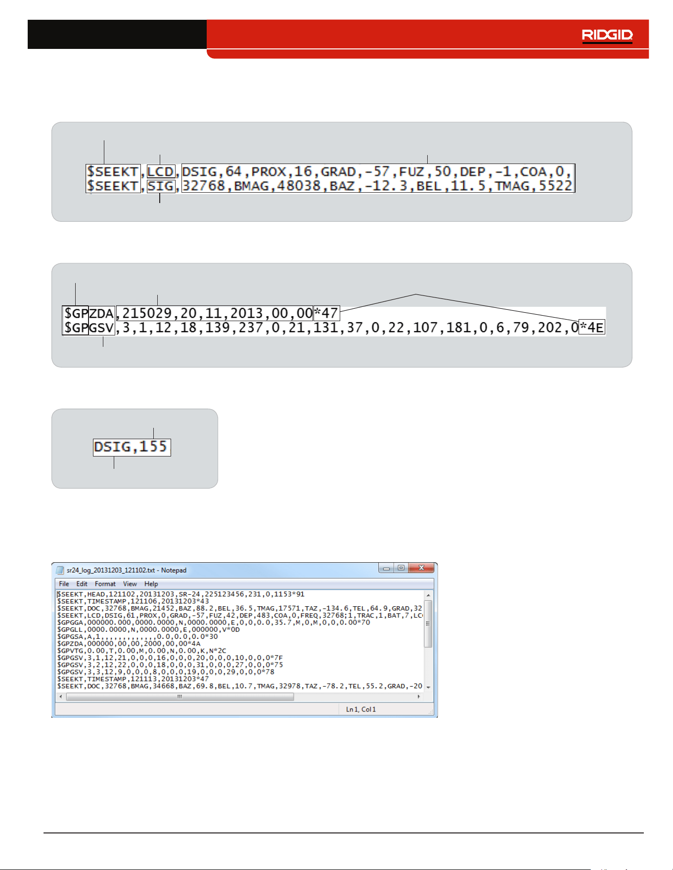
English – 43
Logged data contains a SeekTech String Identifier or NMEA Identifier Prefix, a Grouping Identifier, a Data Abbreviation,
and the Value of the data measured by the SR‑24� SIG or LCD data string begins with the SeekTech String Identifier, fol‑
lowed by the SeekTech Grouping Identifier, Data Abbreviation, and the Value�
Data Abbreviation, Value
(Refer to Appendix C)
SeekTech String Identifier
SeekTech LCD Grouping Identifier
SeekTech SIG Grouping Identifier
GPS data begins with the NMEA Identifier Prefix followed by the Data Abbreviation, NMEA Data, and NMEA Style Check
Sum�
NMEA Identifier Prefix
Data Abbreviation
NMEA Style Data
NMEA Style Check Sum
The Data Abbreviation indicates the type of data and the value indicates the recorded measurement� If the recorded mea‑
surement is zero, the SR‑24 is measuring a zero for that specific data element�
Data Abbreviation
Value
If specific data elements are disabled, they do not appear in the data log file� Refer to the Disable Data section for instruc‑
tions on how to disable specific data elements�
In the data log file, a User‑Initiated Data snapshot contains the time and date the snapshot was taken� The Time stamp
string is located beneath the header�
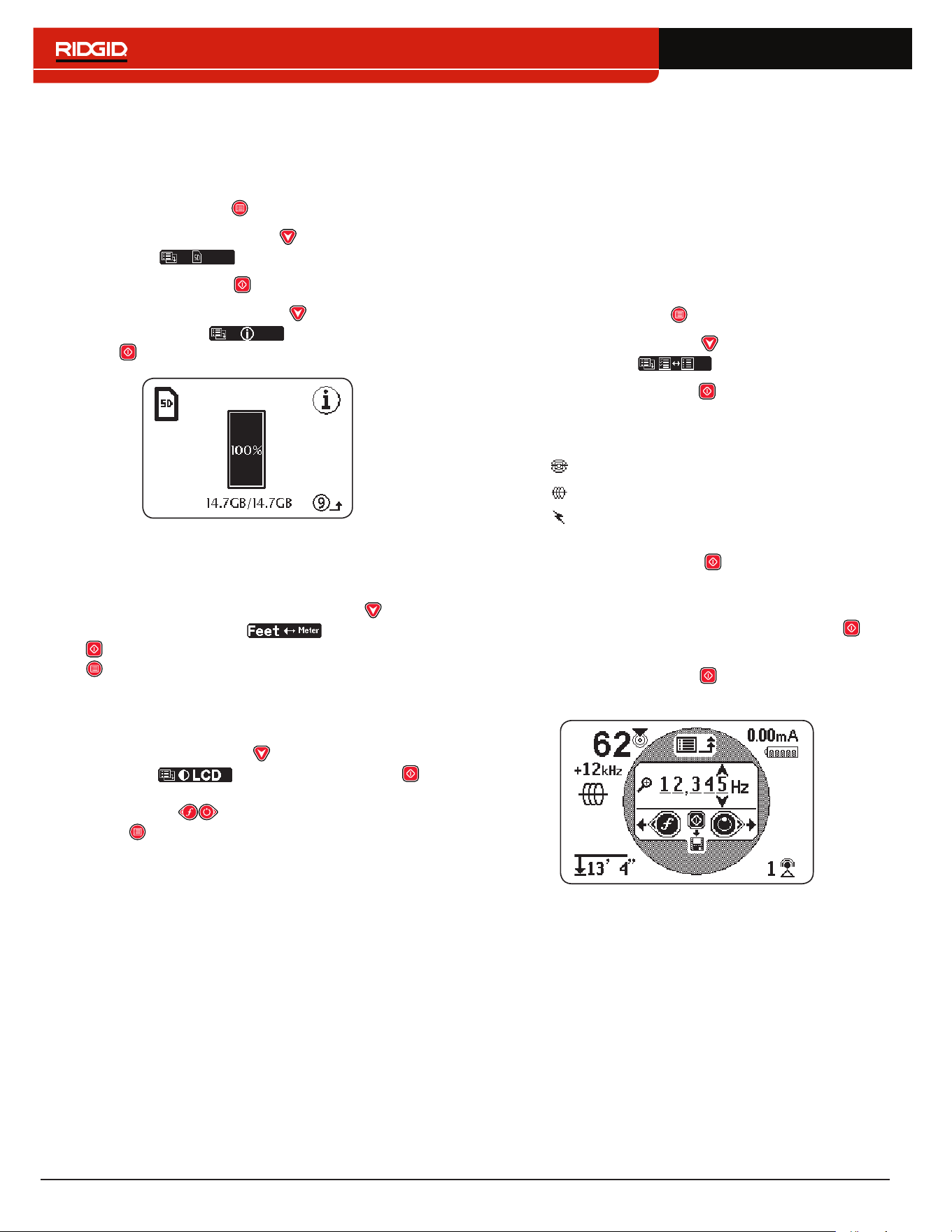
44 – English
SD Card Information
The SD Card Information screen gives you a report of
the amount of space remaining on the SD card� To view
the SD Card Information screen, follow these steps:
1� Press the Menu Key to open the Main Menu�
2� Use the Down Arrow Key to highlight the SD
Card icon �
3� Press the Select Key to open the SD Card menu�
4� Press the Down Arrow Key to navigate to the
Information icon and press the Select
Key �
Units of Measurement
The SR‑24 can display measured depth in meters (m)
or feet (ft)� To change the measurement units, open the
Main Menu and press the Down Arrow Key to navi‑
gate to the Depth Units icon � Press the Select
Key to toggle between Meter or Feet� Press the Menu
Key to save and exit�
LCD Contrast
To adjust the LCD contrast, open the Main Menu and
press the Down Arrow Key to navigate to the LCD
Contrast icon � Press the Select Key to
open the contrast adjustment screen� Use the Left and
Right Arrow Keys to adjust the contrast� Press the
Menu Key to save and exit�
Custom Frequencies
You can create, store, edit, and delete up to 30 unique,
custom frequencies on your SR‑24� You can create cus‑
tom frequencies ranging from 10Hz to 35kHz, making
the SR‑24 compatible with transmitters made by many
manufacturers�
Create Custom Frequencies
To create a new custom frequency, follow these steps:
1� Press the Menu Key to open the Main Menu�
2� Use the Down Arrow Key to highlight the Custom
Frequency icon �
3� Press the Select Key to open the Custom
Frequency menu�
4� There are three types of frequencies you can create
• Sonde
• Active Line Trace
• Passive Line Trace
5� Highlight the type of frequency you want to create
and press the Select Key �
Note: There are additional preprogrammed fre-
quencies that can be added to the active frequen-
cy list from this menu. Press the Select Key to
toggle the frequencies active and inactive.
6� Press the Select Key again to display the
Frequency Input screen�
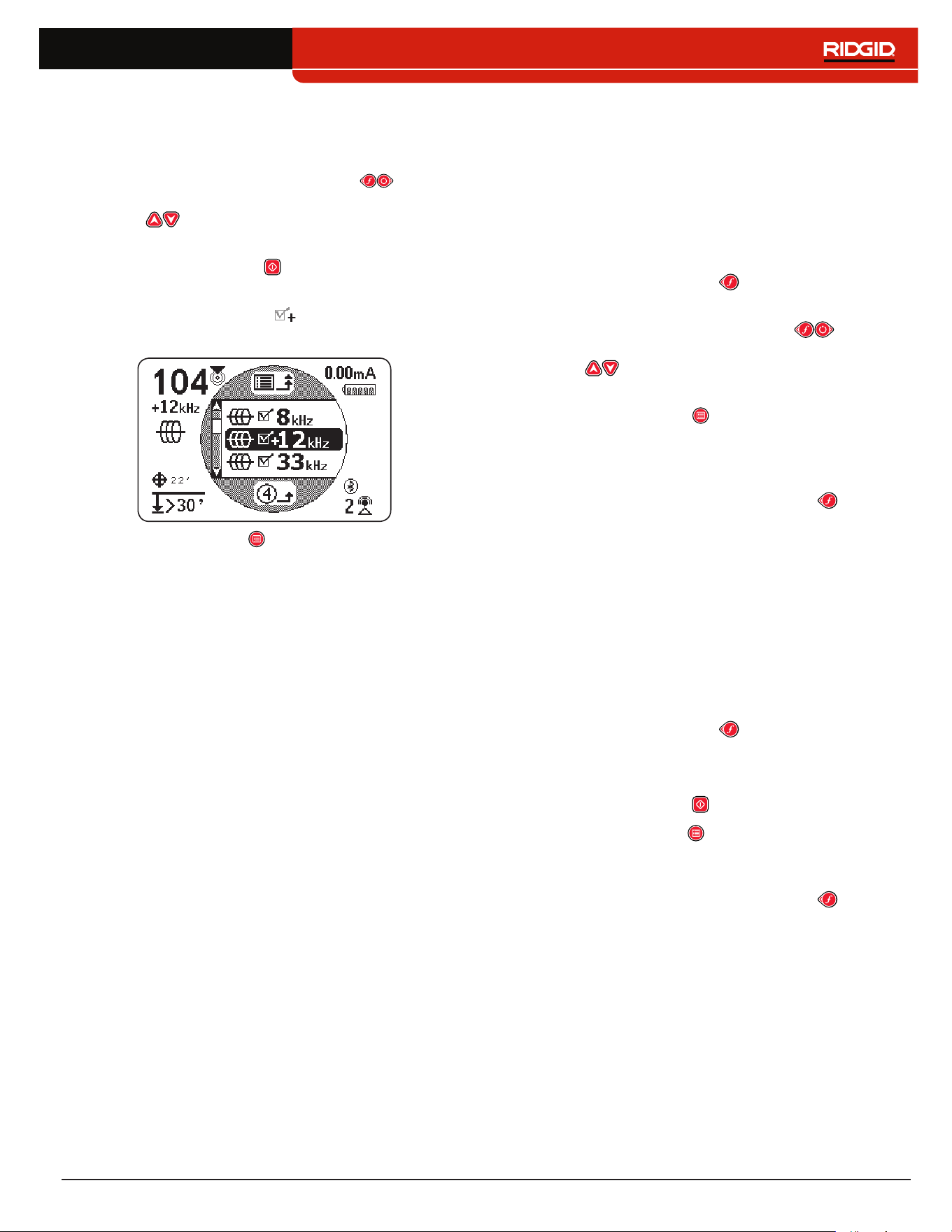
English – 45
Note: You can tune the SR-24 to a frequency by watch-
ing the Signal Strength in the lower right of the screen
while adjusting the frequency.
7� Use the Left and Right Arrow Keys to move
between digits and use the Up and Down Arrow
Keys to increase and decrease the value of
the digits�
8� Press the Select Key to save the custom fre‑
quency�
Note: A plus sign icon appears between the
check box and the frequency.
9� Press the Menu Key to save and exit�
Note: The custom frequency you created is the se-
lected frequency.
Edit Custom Frequencies
To edit custom frequencies, follow these steps:
1� Open the Custom Frequency menu and highlight
the custom frequency that you want to edit�
Note: Refer to steps 1 through 3 in the Custom
Frequencies section for instructions on how to ac-
cess the Custom Frequencies menu.
2� Press the Frequency Key to open the Frequency
Input screen�
3� Use the Left and Right Arrow Keys to move
between digits and use the Up and Down Arrow
Keys to increase and decrease the value of
the digits�
4� Press the Menu Key to save and exit� The cus‑
tom frequency you edited is the selected frequency�
Note: Alternatively, you can highlight the custom fre-
quency that you would like to edit from the Main Menu.
Once highlighted, press the Frequency Key and the
Frequency Input Screen automatically opens.
Delete Custom Frequencies
To delete custom frequencies, follow these steps:
1� Open the Custom Frequency menu and highlight
the custom frequency that you want to delete�
Note: Refer to steps 1 through 3 in the Custom
Frequencies section for instructions on how to ac-
cess the Custom Frequencies menu.
2� Press the Frequency Key to open the Frequency
Input screen�
3� Change all digits to zero�
4� Press the Select Key to delete the frequency�
5� Press the Menu Key to save and exit�
Note: Alternatively, you can highlight the custom frequen-
cy that you would like to delete from the Main Menu.
Once highlighted, press the Frequency Key and the
Frequency Input Screen automatically opens.
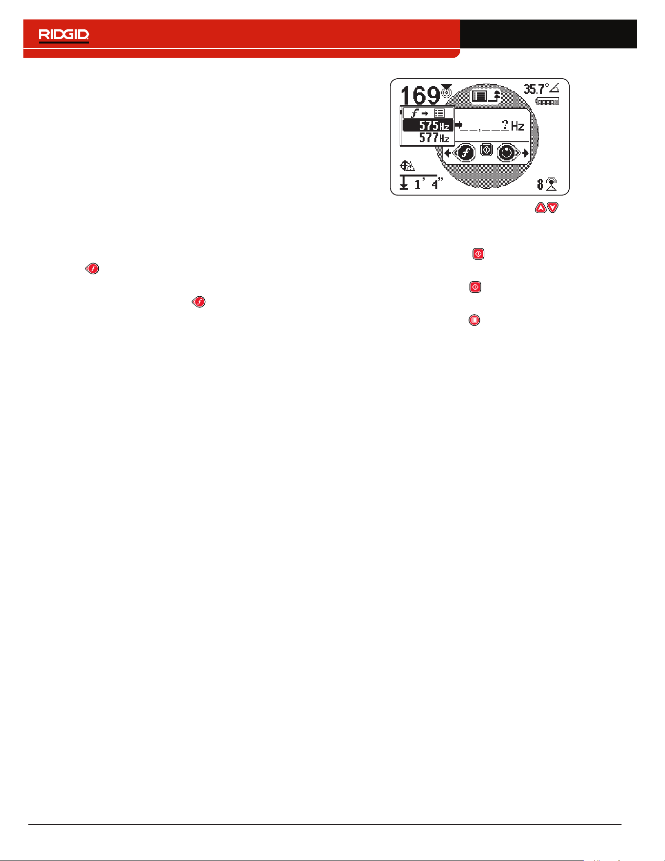
46 – English
Commonly Used Frequency List
In addition to creating custom frequencies, you can se‑
lect frequencies commonly used by manufacturers of
other transmitters�
To access the commonly used frequency list, follow
these steps:
1� Access the Frequency Input screen through the
Custom Frequencies menu�
Note: Refer to the Custom Frequencies section for
instructions on how to access the Frequency Input
screen.
2� In the Frequency Input screen, use the Left Arrow
Key to move the cursor to the left side of the
screen�
3� Press the Frequency Key one space past the
far left digit to display the list of commonly used fre‑
quencies�
4� Use the Up and Down Arrow Keys to highlight
the frequency that you want to add to the list of cus‑
tom frequencies�
5� Press the Select Key to enter the frequency into
the blank digit fields�
6� Press the Select Key again to save the frequency
as a custom frequency�
7� Press the Menu Key to exit�
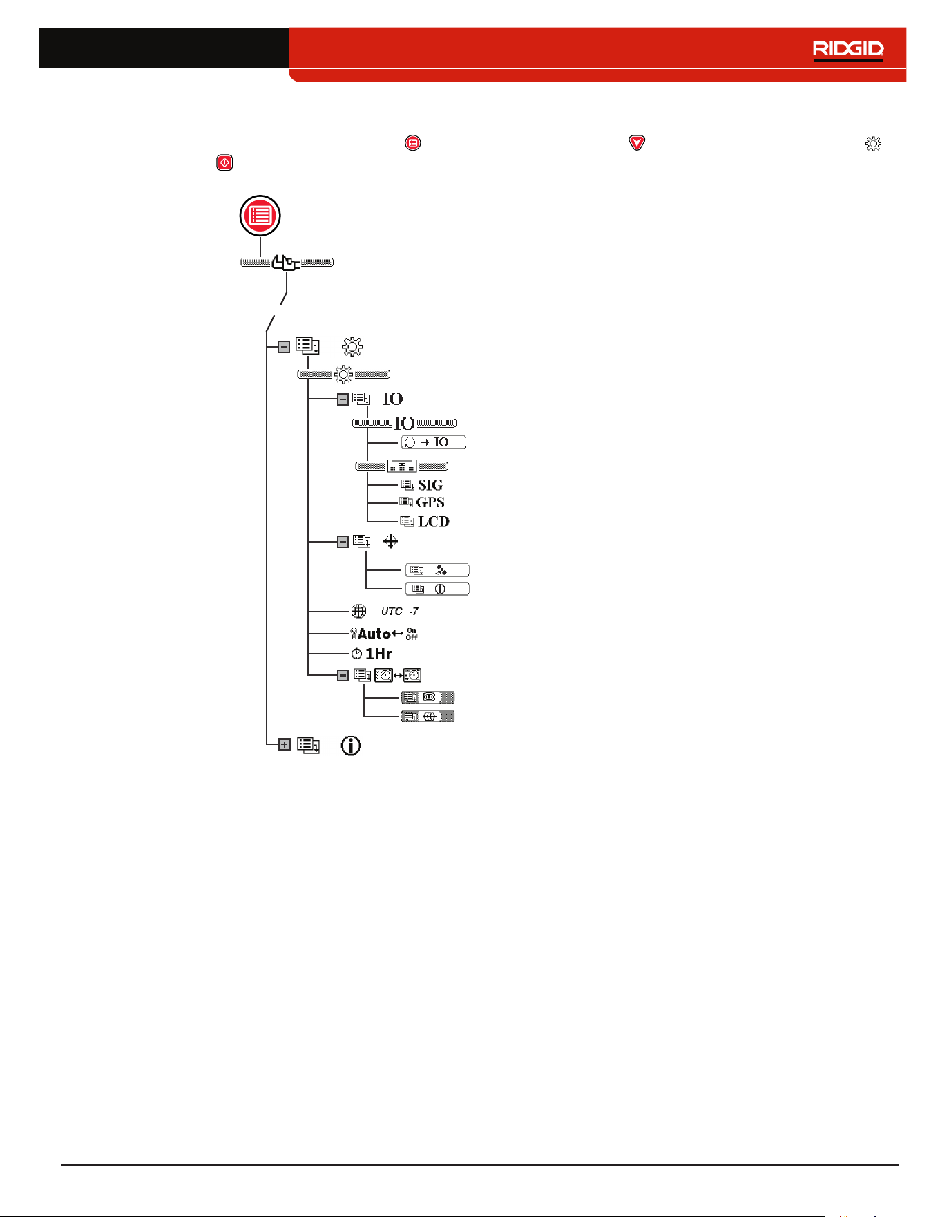
English – 47
Settings
To open the Settings menu, press the Menu Key and use the Down Arrow Key to navigate to the Settings icon �
Press the Select Key to open the Settings menu�
Settings
Data Output (SR‑24 only)
Disable SIG Data
Signal Quality
Time Zone
Backlight
Auto‑shutdown
Continuous Data Output
GPS Information
Disable GPS Data
Disable LCD Data
Options
GPS (SR‑24 only)
Information
Customizing Display Elements
Sonde Display Mode
Line Trace Display Mode
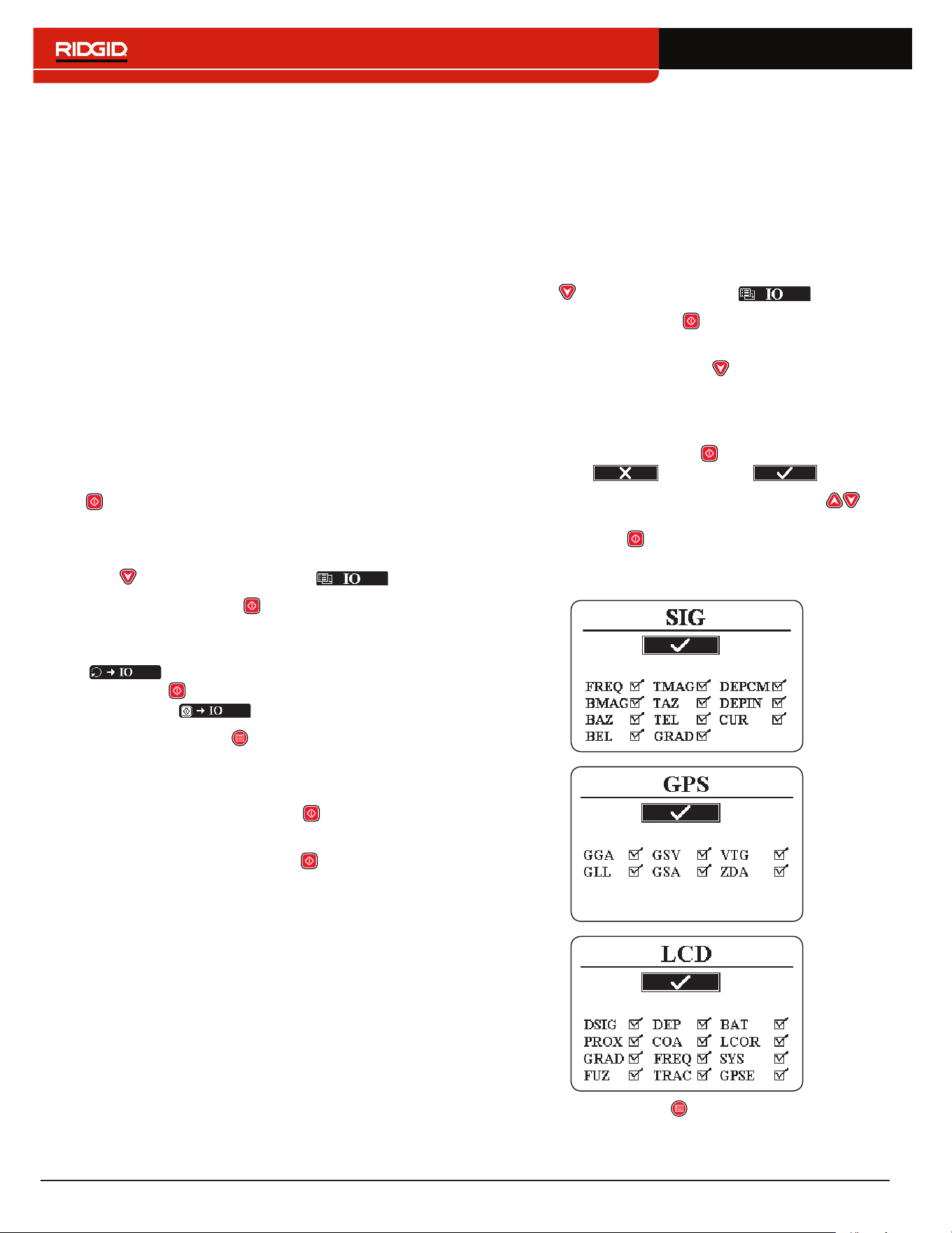
48 – English
IO Menu
The following section applies to the SR-24 only.
The IO feature sends the SR‑24’s locate data to the in‑
ternal SD card, or to a Bluetooth device if one is avail‑
able, or to both simultaneously�
Note: Refer to the SD Card section for information about
the SD card and how to read the data log file.
Data can be logged continuously (default), or manual‑
ly at specific points during a locate, by enabling User‑
Initiated Data Output�
You can disable an entire category or specific elements
within a category� Refer to Appendix C for descriptions of
the data logging elements�
User-Initiated Data Output
The User‑Initiated Data Output function is disabled by
default� Enable User‑Initiated Data Output to set the
SR‑24 to only output data when you press the Select
Key �
To enable User‑Initiated Data Output, follow these steps:
1� Open the Settings menu and use the Down Arrow
Key to navigate to the IO icon �
2� Press the Select Key to open the Data Output
menu�
3� Highlight the Continuous Data Output icon
in the Data Output menu and press the
Select Key to toggle between disabled (default)
and enabled �
4� Press the Menu Key to save and exit�
To use the User‑Initiated Data Output function during the
locate, do one of the following:
• A short press on the Select Key to output a snap‑
shot of the instant data�
• A long press on the Select Key to output a snap‑
shot of the data averaged�
Note: When performing a long press, the SR-24 outputs
data averaged at the same time the Depth Average re-
port displays.
Data Selection
Use these menus to enable and disable specific compo‑
nents of the data output� Disable all or part of a specific
data element to reduce the amount of data that is logged
and output onto the internal SD card�
All categories of data are output by default� To disable
all or part of a specific data element, follow these steps:
1� Open the Settings menu and use the Down Arrow
Key to highlight the IO icon �
2� Press the Select Key to open the Data Output
menu�
3� Press the Down Arrow Key to navigate to the cat‑
egory of data that you want to disable: SIG, GPS,
or LCD�
• To disable or enable all data elements as a group
press the Select Key to toggle between dis‑
abled and enabled �
• Or, use the Up and Down Arrow Keys to
highlight a specific data element and press the
Select Key to disable and enable the individu‑
al data element by checking and unchecking the
box next to the data abbreviation�
4� Press the Menu Key to save and exit�
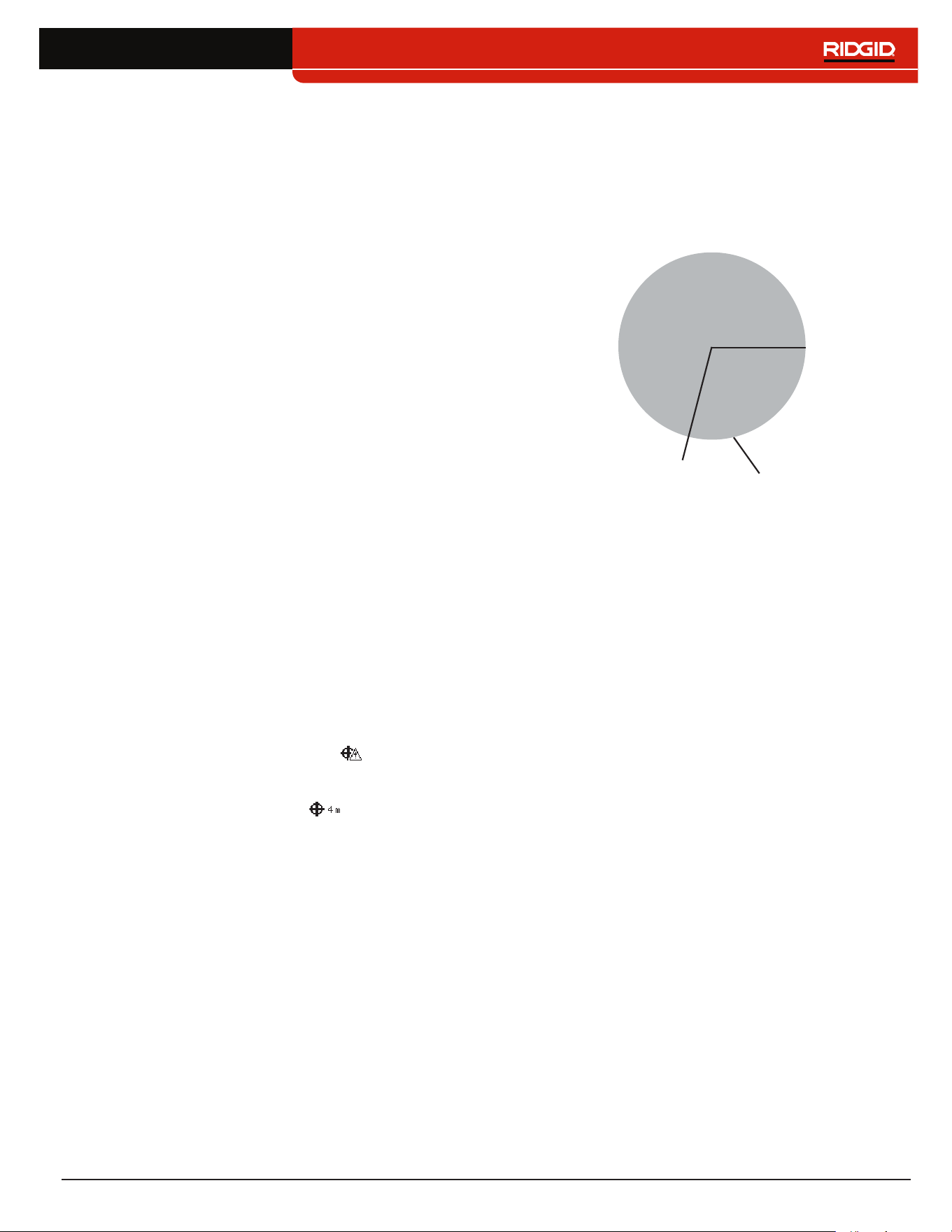
English – 49
SR-24 GPS
The following section applies to the SR-24 only.
The SR‑24 has an internal GPS receiver that provides
location data to the receiver� The GPS data is stored on
the SD card and can be logged to a Bluetooth device
through a Bluetooth connection�
Note: Refer to the Data Logging section for instructions
on how to export data log files to your computer.
The SR‑24 is compatible with Bluetooth 2�0 devices
including many phones, tablets, and GPS units� Refer
to www�RIDGID�com/SR24 for a list some models that
have been tested to work with the SR‑24�
GPS Accuracy
GPS accuracy is measured in a variety of different
ways, all are statistical in nature� According to the doc‑
umentation supplied by the manufacturer of the inter‑
nal SiRFstarIV GPS module, its nominal accuracy is
“< 2�5 m (65 percent, 24 hour static, ‑130 dBm)�” This
indicates that under ideal conditions, the GPS receiv‑
er is capable of accuracy such that each point collect‑
ed would have a 65 percent chance of being inside a
circle with a 2�5m [8�2ft] radius extending from the true
location� It is able to do this under ideal conditions with
a strong signal (‑ 130dBm) over a 24 hour test, during
which the GPS unit is not moving�
The actual accuracy of a GPS device is highly variable
and based on many factors such as obstacles in the
physical environment, atmospheric conditions, and the
quality of the GPS satellite constellation�
The GPS icon displayed on screen indicates the status
of the position fix� The GPS Status icon indicates that
the GPS is searching for a position solution� When the
SR‑24 GPS finds a position solution, the GPS Estimated
Positional Error icon, for example , appears on the
SR‑24 screen to indicate the SiRFstarIV’s position lock
status and to provide an estimated positional error�
The estimated positional error indicates that a given
solution is within the stated accuracy, approximately 65
percent of the time� In the following example, 65 percent
of the solutions would be within a circle with a 4m [13ft]
radius� For example, the following graphic shows the
SiRFstarIV’s actual position is inside the circle, 65 per‑
cent of the time�
4 m
[13ft]
Estimated Positional Error
Reported Position
×
Using the SR-24 with External GPS Software
The SR‑24 can communicate the SIG, GPS, or LCD
data it collects to external GPS mapping devices and
GIS software� To interpret the SR‑24’s data, the exter‑
nal GPS software and the SR‑24 must be connected
through Bluetooth and the GPS software must be able to
interpret data from a Bluetooth source�
Note: For specifications on external GPS software accu-
racy, consult the external GPS vendor.
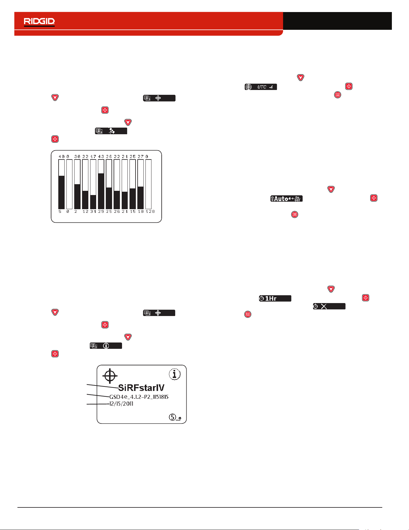
50 – English
Signal Quality
You can monitor the SR‑24’s internal GPS receiver sig‑
nal quality from the GPS menu� To open the GPS menu,
follow these steps:
1� Open the Settings menu and press the Down Arrow
Key to navigate to the GPS icon �
2� Press the Select Key to open the GPS menu�
3� Press the Down Arrow Key to navigate to the
Signal Quality icon and press the Select
Key to open the Signal Quality screen�
Each bar indicates the signal quality of different satel‑
lites� Higher numbers indicate better signal quality� Signal
quality can be affected by the availability of a clear view
to the signal and by the number of satellites that are cur‑
rently available�
GPS Information
To view the GPS Information screen, follow these steps:
1� Open the Settings menu and press the Down Arrow
Key to navigate to the GPS icon �
2� Press the Select Key to open the GPS menu�
3� Press the Down Arrow Key to navigate to the
Information icon and press the Select
Key �
GPS Firmware
Date of Build
GPS Module
Note: GPS is always on. To disable GPS data from log-
ging to the internal SD card or your Bluetooth device,
refer to the Disable Data section.
Time Zone
Change the time zone setting in the Time Zone screen�
To change the time zone, open the Settings menu and
press the Down Arrow Key to navigate to the Time
Zone icon � Press the Select Key to cycle
through time zones� Press the Menu Key to save and
exit�
Note: Look up your time zone code at 24timezones.com
LCD Backlight
The SR‑24 has a light sensor built into the Keypad that
can automatically adjust the LCD backlight� The default
setting, Auto, is configured to automatically turn on the
backlight for the LCD in low light conditions�
To change the backlight settings, open the Settings
menu and press the Down Arrow Key to navigate to
the Light Bulb icon � Press the Select Key
to toggle between the “On,” “Off,” and “Auto” backlight op‑
tions� Press the Menu Key to save and exit�
Auto-shutdown
By default, the SR‑24 powers off automatically if no
Keys are pressed for over one hour� If you disable Auto‑
shutdown the SR‑24 will stay powered on until the batter‑
ies are fully discharged�
To change the Auto‑shutdown setting, open the Settings
menu and press the Down Arrow Key to navigate to
the Clock icon � Press the Select Key to
toggle between one hour and off � Press the
Menu Key to save and exit�
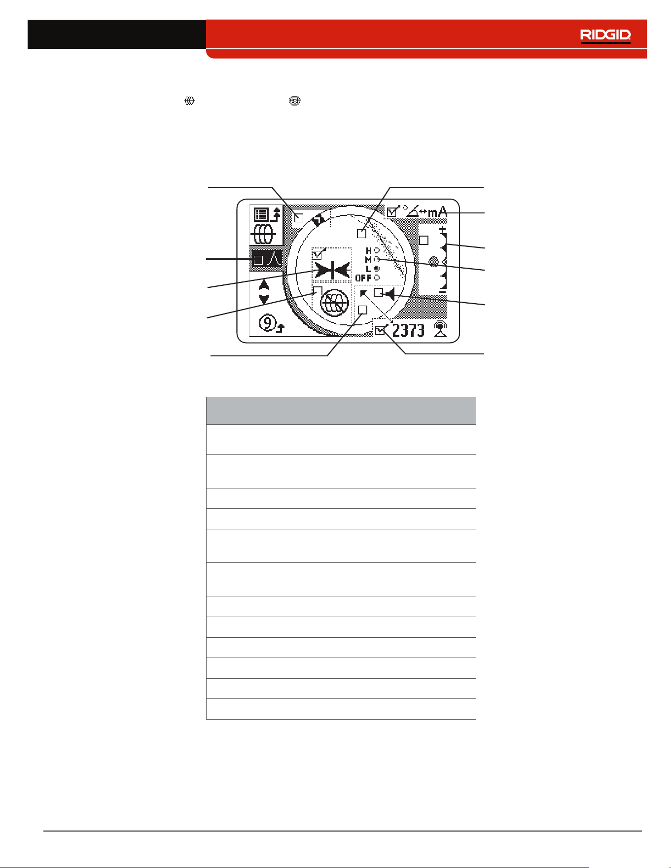
English – 51
Customizing Display Elements
In Active Line Trace Mode and Sonde Mode you can customize the display elements that appear on screen� A
checked box means the element is enabled and an unchecked box means it is disabled� From the Customizing Display
Elements Screen, press the Select Key to check and uncheck boxes�
Note: Any changes made to Active Line Trace Mode also apply to Passive Line Trace Mode and vice versa.
No Signal
Max Signal Indicators
Signal Angle and Current
Measurement
Signal Focus Control
Guidance Arrows
Proximity Threshold Control
Signal Strength Audio
Tracing Line Distortion
Sensitivity
Center Signal Strength
Signal Strength Display
Distortion Line Display
Note: The settings shown here are the SR-24’s defaults.
Customizable Display Elements
Element
Line Trace
Mode
Sonde
Mode
Race Track, Watermark,
Level Pointer
No Signal Icon
Center Signal Strength
Proximity Threshold
Control
Tracing Line Distortion
Sensitivity
Distortion Line
Guidance Arrows
Current Measurement
Signal Angle
Signal Strength Audio
Signal Strength
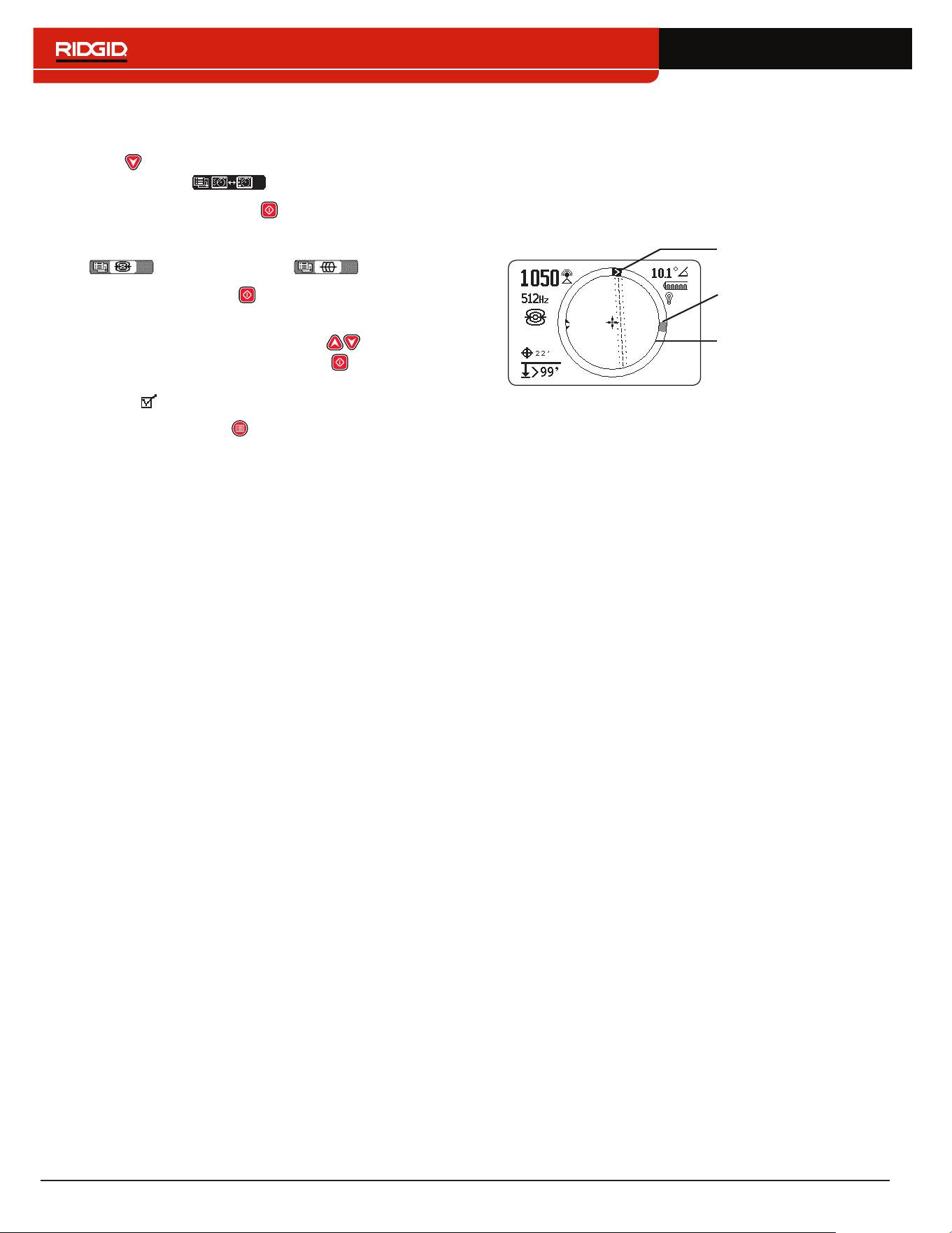
52 – English
To customize display elements, follow these steps:
1� Open the Settings menu and press the Down Arrow
Key to navigate to the Customizing Display
Elements icon �
2� Press the Select Key to open the Display
Elements menu and highlight the mode you want
to customize the display for: either Sonde Mode
or Line Trace Mode �
3� Press the Select Key to open the customization
screen�
4� Use the Up and Down Arrow Keys to highlight
an option and press the Select Key to check and
uncheck the options� Check the box to enable the
feature and uncheck the box to disable it�
5� Press the Menu Key to save and exit�
Max Signal Indicators
The Race Track, Watermark, and Level Pointer work to‑
gether to dynamically give you points of reference for the
highest signal the SR‑24 detects� The information pro‑
vided by these indicators can find the maximum signal
strength during your locating process�
Level Pointer
Watermark
Race Track
The Race Track is the circular track around the Active
View Area� As you move the receiver, the Level Pointer
moves clockwise around the Race Track as Signal
Strength increases and regresses counterclockwise
when the Signal Strength decreases� When the Signal
Strength begins to decrease, a Watermark is left behind
to represent the highest signal level detected�
In Sonde Mode, the Watermark represents the highest
Signal Strength detected by the receiver� In Line Trace
Modes the Watermark represents the highest Proximity
Number reached�
In many cases when the Watermark appears and the
Level Pointer begins moving counter clockwise, then you
may be moving away from the target line�
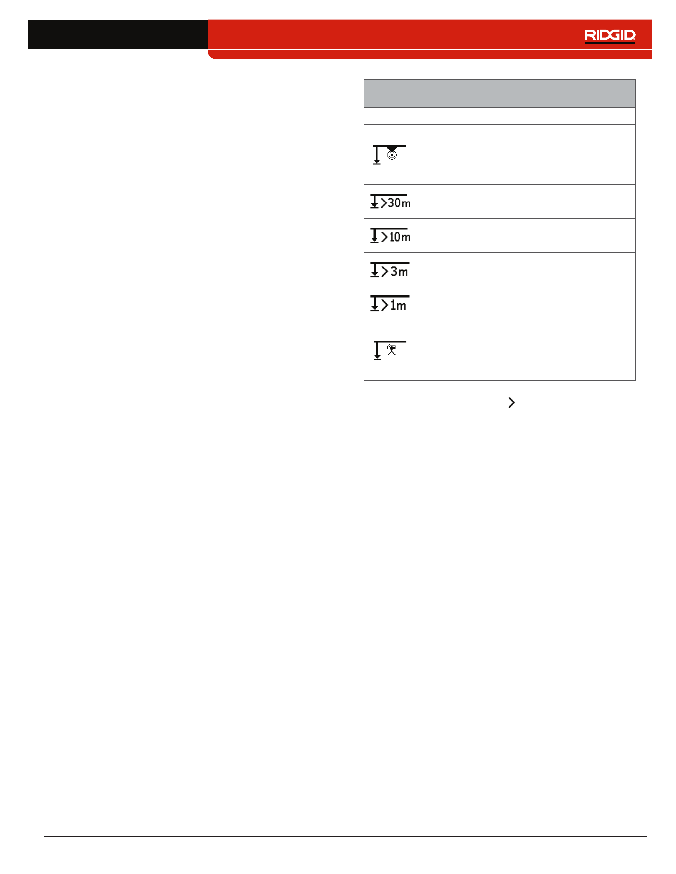
English – 53
Proximity Number and Threshold
The Proximity Number is designed to increase as the
SR‑24 gets closer to the target line� In many cases, max‑
imizing the Proximity Number is a more accurate way
of pinpointing the location of the target line than Signal
Strength alone�
Use the Proximity Threshold Control to tell the receiver
to ignore targets with depth measurements outside of a
defined range� By setting a threshold for the maximum
depth you can reduce the amount of spurious display ar‑
tifacts that may distract from the locating process�
If the measured depth of the target line is less than the
proximity threshold, the Proximity Number appears as
zero and the Mapping Display is suppressed� If the mea‑
sured depth is greater than the proximity threshold, the
Proximity Number is displayed and the Mapping Display
is shown�
Proximity Threshold Settings
Depth Control
No threshold, no suppression, and
allows negative depth display� Negative
depth display appears on a black
background in the bottom left corner�
For detections where measured depth
is no greater than 30m [98ft]�
For detections where measured depth
is no greater than 10m [33ft]�
For detections where measured depth
is no greater than 3m [10ft]�
For detections where the measured
depth is greater than 1m [3ft]�
Displays the Signal Strength to screen
center, suppresses the map display,
allows negative depth to display, and
audio signals reflect Signal Strength�
Note: The Greater Than icon only appears when the
receiver detects utility lines that are deeper than the
depth shown.
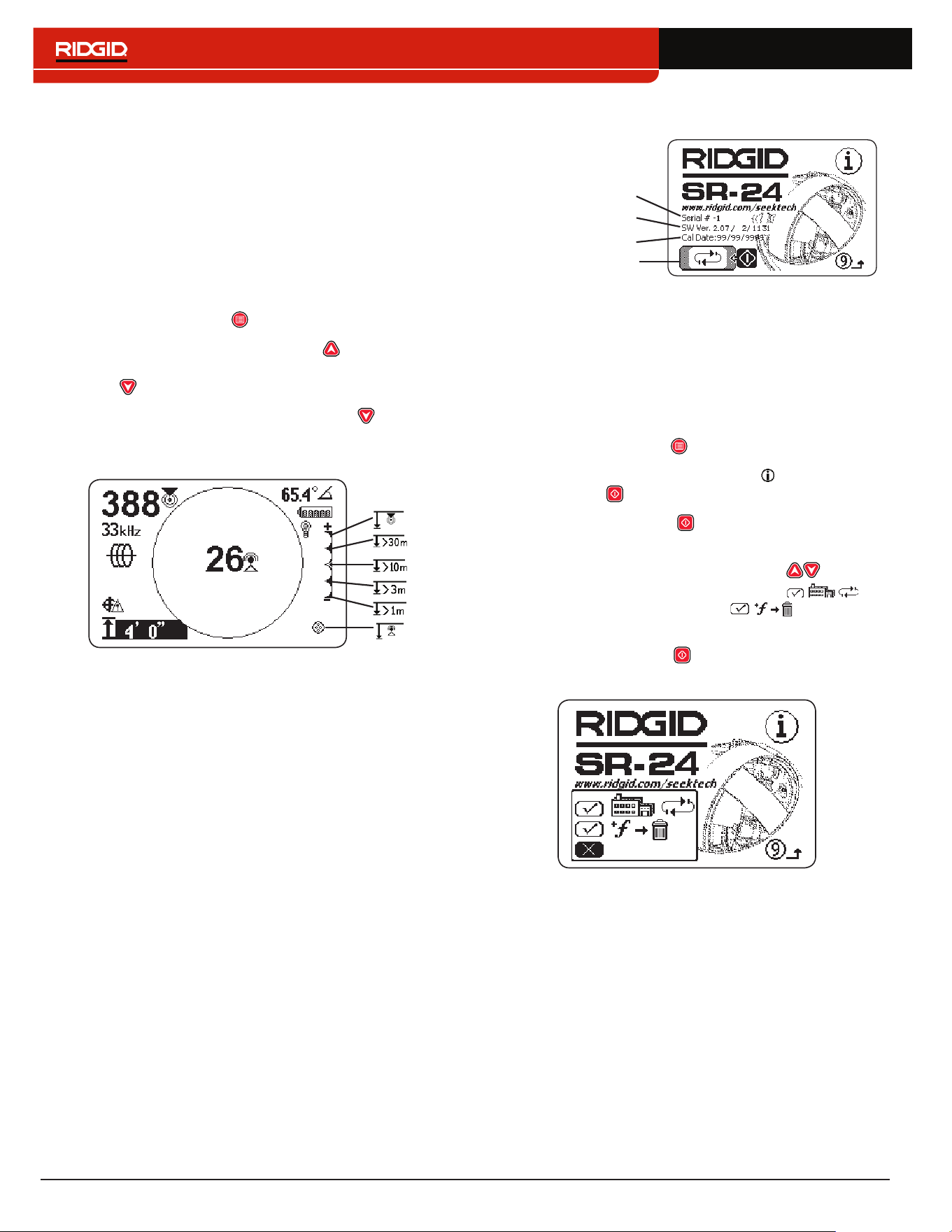
54 – English
To adjust the Proximity Threshold Control, follow these
steps:
1� Activate the Proximity Threshold Control in the dis‑
play settings�
Note: Refer to the Customizing Display Elements
section for instructions on how to activate the
Proximity Threshold Control.
2� Check the box to the Proximity Threshold Control
setting�
3� Press the Menu Key to save and exit�
4� Press and hold the Up Arrow Key for half a sec‑
ond to set the threshold higher or the Down Arrow
Key to set the threshold lower�
5� Press and hold the Down Arrow Key past the
lowest Proximity Threshold range and the Signal
Strength appears in the center of the screen�
Note: The depth measurement appears on a black back-
ground when the SR-24 is measuring a negative depth
(signal from above the SR-24).
Proximity Threshold Control
When the measured depth is greater than the Proximity
Threshold Control limit set in the menu, the sound is
muted� By default, the Proximity Threshold Control is dis‑
abled� When the Proximity Threshold Control is disabled,
the sound automatically mutes when measured depth is
greater than 30m [99ft]�
Information Options
Serial Number
Factory Reset
Software Version
Calibration Date
Factory Reset Options
The SR‑24 contains two reset options:
• Complete factory reset of the device
• Delete custom frequencies only
To do a factory reset, follow these steps:
1� Press the Menu Key to open the Main Menu�
2� Navigate to the Information icon and press the
Select Key �
3� Press the Select Key to open the Factory Reset
menu�
4� Press the Up and Down Arrow Keys to high‑
light either a complete factory reset or
restore factory frequencies and delete
custom frequencies�
5� Press the Select Key to select your desired reset
option�

English – 55
Maintenance and Support
Cleaning
WARNING
Remove batteries prior to cleaning the SR-24 to re-
duce the risk of electrical shock.
Do not use liquid or abrasive cleaners, solvents, or scrap‑
ing tools to clean the SR‑24� Do not immerse in water or
allow any liquid to enter the unit�
Clean with damp cloth and mild detergent� Only clean
screen with cleaners approved for use on LCD screens�
Accessories
WARNING
The following accessories have been designed for
use with the SR-24. Other accessories may become
hazardous when used with the SR-24. To reduce the
risk of serious injury, only use accessories specif-
ically designed and recommended for use with the
SR-24.
The following accessories have been designed for use
with the SR‑24:
• RIDGID SeekTech Transmitters
• ST‑305
• ST‑510
• ST‑33Q+
• RIDGID SeekTech Inductive Signal Clamp
• Sondes
• FloatSonde
• Battery Sonde
• SeeSnake camera integrated Sonde (Flexmitter)
Transportation and Storage
Store and transport your equipment with the following in
mind:
• Keep in a locked area out of the reach of children
and people unfamiliar with its operation�
• Put in a dry place to reduce risk of electrical shock�
• Store away from heat sources such as radiators,
heat registers, stoves, and other products (including
amplifiers) that produce heat�
• Storage temperature should be ‑20°C to 60°C [‑4°F
to 140°F]�
• Do not expose to heavy shocks or impacts during
transportation�
• Remove the batteries before shipping and before
storing for extended periods of time�

56 – English
Service and Repair
WARNING
Improper service or repair can make the SR-24 un-
safe to operate.
Service and repair of the SR‑24 must be performed by
a RIDGID Independent Authorized Service Center� To
maintain the safety of the tool, make sure a qualified re‑
pair person services your equipment using only identi‑
cal replacement parts� Discontinue using the SR‑24, re‑
move the batteries, and contact service personnel under
any of the following conditions�
• The equipment does not operate normally when op‑
erating instructions are followed�
• The equipment exhibits a distinct change in perfor‑
mance�
• The equipment has been dropped or damaged�
• Liquid has been spilled or objects have fallen into
the equipment�
For information on your nearest Ridge Tool Technical
Service Department or any service or repair questions:
• Contact your local RIDGID distributor�
• Go to www�RIDGID�com�
• Email the RIDGID Technical Services Department at
rtctechservices@emerson�com�
• Call 1‑800‑519‑3456 (USA and Canada only)�
Disposal
Parts of the SR‑24 contain valuable materials that can
be recycled� There are companies that specialize in re‑
cycling that may be found locally� Dispose of the com‑
ponents in compliance with all applicable regulations�
Contact your local waste management authority for more
information�
For EC countries: Do not dispose of electrical
equipment with household waste!
According to the European Guideline 2002/96/
EC for Waste Electrical and Electronic
Equipment and its implementation into nation‑
al legislation, electrical equipment that is no longer us‑
able must be collected separately and disposed of in an
environmentally correct manner�

English – 57
Troubleshooting
Problem Probable Fault Solution
SR‑24 locks up during use —
Power off the SR‑24 and then power on� Remove
the batteries if the unit will not turn off� Replace the
batteries if low�
SR‑24 will not pick up signal —
Make sure the mode and frequency are correctly
set� Examine the transmitter connections and make
necessary improvements� Relocate the transmitter,
change the grounding or frequency, modify the
proximity threshold, or change the signal focus
control settings�
While line tracing, lines jump
around the screen in the
mapping display
SR‑24 not receiving the
signal or interference is
present�
Make sure the transmitter is well connected and
grounded� Point the SR‑24 at either lead to ensure
that adequate levels of current are flowing on the
target line�
Use a higher frequency, connect to a different point
on the line, or switch to Inductive Mode�
Determine and eliminate the source of distortion�
Make sure the batteries are fully charged�
While locating a Sonde,
lines jump around the
screen
Sonde batteries may be low
or Sonde may be too far
away�
Make sure the batteries in the Sonde are fully
charged�
Start the Sonde locate with the Sonde located closer
or perform an area search�
Place the antenna close to the Sonde to verify the
signal� Note that Sondes have difficulty emitting
signals through cast iron and ductile iron lines�
Increase the proximity threshold and try lower
settings of signal focus control to improve the focus
on weaker signals�
Distance between the
Sonde and either pole not
equal
Sonde may be tilted or cast
iron to plastic transition�
Refer to the section of locating tilted Sondes�
Unit acts erratic and does
not power off
Batteries may be low� Replace batteries�
Display appears completely
dark or completely light
when on
When the SR‑24 gets too
hot, the LCD will darken�
When it gets too cold, it will
lighten�
Power off the SR‑24 and then power on� Adjust the
LCD contrast�
No sound is audible —
Adjust the sound level� Verify that the Proximity
Number is greater than zero�
The SR‑24 will not power on
Faulty batteries or blown
fuse�
Check the orientation of the batteries and that they
are fully charged� Make sure the battery contacts are
not damaged� Fuse is not user‑replaceable, contact
an Authorized Service Center�

58 – English
Appendices
Appendix A: Glossary of Terms
• Active Frequencies. A frequency with the box
checked on the Main Menu � To cycle through active
frequencies press the Frequency Key �
• Active Line Tracing . A mode of locating using a
line transmitter to induce a chosen frequency onto a
line� The receiver traces the line by detecting the fre‑
quency�
• Active View Area. The area inside the circle in the
center of the display screen� The Tracing Line, Sonde
Pole, and Equator symbols appear in the Active View
Area�
• Bleed Over. Bleed over happens when the frequen‑
cy from the transmitter couples current onto nearby
non‑target lines� The SR‑24 can receive the same fre‑
quency on multiple non‑target lines�
• Clear Signal. When the receiver detects a strong, un‑
distorted current flowing on the target line� A clear sig‑
nal depends on good conductivity, good grounding,
and adequate current through the target line�
• Clipping. When the signal is too strong to be pro‑
cessed all at once by the SR‑24’s signal processor�
When clipping occurs, a warning flashes on the screen�
• Common Bonding. When more than one line is
grounded through the same ground connection�
Common bonding can cause the same active frequen‑
cy to be coupled onto non‑target utilities� �
• Coupling. The transfer of energy between the target
utility and other non‑target utilities�
• Cross Hairs . The symbol that represents the re‑
ceiver’s location relative to the field of the target line�
The cross hairs appear at the center of the Active View
Area�
• Current Measurement (mA). The level of current in
miliamps based on the field strength detected by the
Omnidirectional antennas and the measured depth�
• Distortion. The impact of nearby fields, near‑by con‑
ductors, magnetic flux, or other interference on the
circular electromagnetic field� Distortion is detected
by comparing the information from the Tracing Line,
Proximity Number, Signal Strength, measured depth,
and Signal Angle readings from the upper and lower
antennas�
• Distortion Line. The dashed line that appears in the
Active View Area when the Tracing Line Distortion
Response is disabled� The Distortion Line indicates
the location of the target utility measured by the Upper
Antenna� Use the Distortion Line to visualize distortion
in the detected field�
• Frequency. The number of times per second that an
electromagnetic field forms and collapses� Frequency
is expressed in hertz (Hz) or kilohertz (kHz)�
• Guidance Arrows . The arrows icon in the
Active View Area that indicates where the target line’s
field is balanced�
• Level Pointer. A solid pointer that moves around a cir‑
cular track to indicate the Signal Strength detected�
• Measured Depth. The calculated depth, distance to
the Sonde, or the apparent center of the target line�
Potholing may be required before excavation to deter‑
mine accuracy of the target line’s physical depth�
• Omnidirectional Antenna. Proprietary antenna tech‑
nology capable of simultaneously detecting electro‑
magnetic fields on three axes�
• OmniSeek
®
. A Passive Line Trace Mode that
searches all power and radio frequency bandwidths
simultaneously�
• Passive Line Tracing . A mode of line tracing that
does not require a transmitter to place a current on the
line� The SR‑24 is able to locate by receiving current
through the target line from an external energy source�
• Pole . Represents where the field lines from the
Sonde vertically exit the ground� One of the two ends
of a dipole field�

English – 59
• Proximity Number . A number that reflects how
close the receiver is to the target line when in either
Active Line Trace Mode or Passive Line Trace Mode�
The Proximity Number is calculated based on the sig‑
nal received by the two Omnidirectional antennas� The
Proximity Number increases with signal strength and
also increases with decreasing depth�
• Proximity Threshold. A control which decreases pos‑
sible distortion by constraining the receiver’s locating
range�
• Radio Frequency Broadband . The SR‑24 search‑
es for signal energy within a specific range of frequen‑
cies�
• Signal Angle . The angle of the target line’s field rel‑
ative to the horizontal plane�
• Signal Strength . The strength of the target line’s
field signal as detected by the lower Omnidirectional
antenna in three dimensions�
• Sonde . A self contained transmitter that emits a di‑
pole field and is used to locate a point within an under‑
ground pipe, tunnel, or conduit�
• Target Line. The utility line that your transmitter is
connected to on a locate�
• Tracing Circuit. The complete flow of electrical cur‑
rent from the transmitter through the conductor and
back to the ground� Weak current will cause a weak
signal�
• Tracing Line Distortion Response. When the Tracing
Line appears fuzzy because distortion is present�
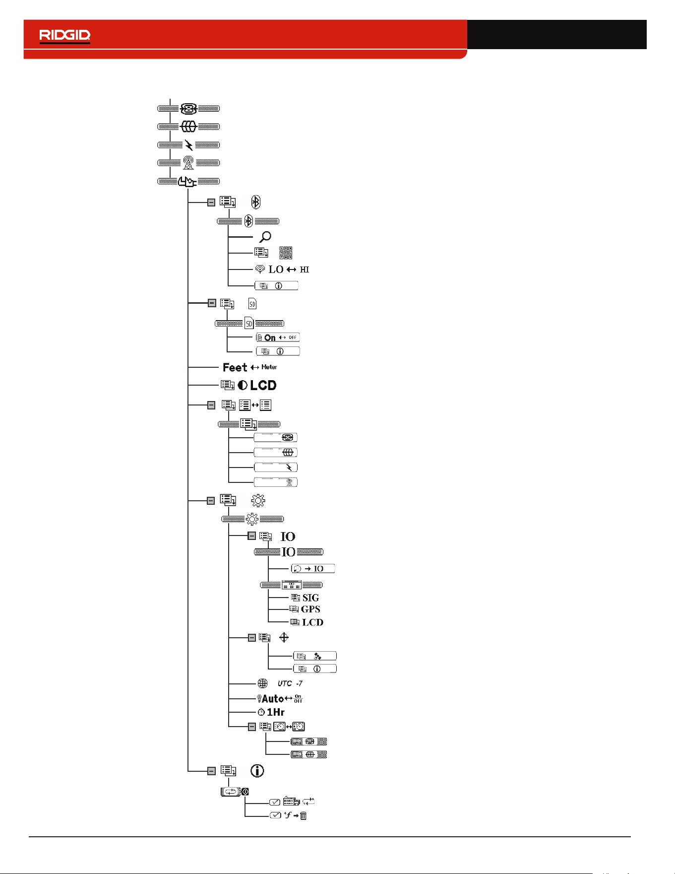
60 – English
Appendix B: Main Menu Map
SR-24
SR-24
SR-24
SR-24
Delete Custom Frequencies
Factory Reset
Options
Bluetooth
Search for Devices
Bluetooth Pin
Bluetooth Power
Custom Frequencies
LCD Contrast
Units of Measurement
Sonde
Active Line Trace
Passive Power
Passive Radio + OmniSeek
Settings
Line Trace Display Mode
Sonde Display Mode
Customizing Display Elements
Data Output
Disable SIG Data
Data Logging
Time Zone
Backlight
Auto‑shutdown
Continuous Data Output
GPS
Disable GPS Data
Disable LCD Data
Passive Power Frequencies
Active Line Trace Frequencies
Sonde Frequencies
Passive Radio Frequencies + OmniSeek
Information
Bluetooth Information
SD Card Information
Signal Quality
GPS Information
SD Card

English – 61
Appendix C: Data Logging Abbreviations
Data Logging Abbreviations
Main
Menu
Header
String
Identifier
SeekTech
Grouping
Identifier
Data
Abbreviation
Description
SIG $SEEKT SIG
FREQ The signal frequency (Hz) of the SR‑24�
BMAG
The magnitude of the signal received by the Lower Antenna in
the range of ‑2
15
to 2
15‑1
� Clipping may be occurring when the
magnitude value is unstable�
BAZ
The azimuth angle (degrees) of the signal received by the Lower
Antenna�
BEL
The elevation angle (degrees) of the signal received by the Lower
Antenna�
TMAG
The magnitude of the signal received by the Upper Antenna in
the range of ‑2
15
to 2
15‑1
� Clipping may be occurring when the
magnitude value is unstable�
TAZ
The azimuth angle (degrees) of the signal received by the Upper
Antenna�
TEL
The elevation angle (degrees) of the signal received by the Upper
Antenna�
GRAD The gradient value from ‑32768 to 32767�
DEPCM The depth of the target line in centimeters (cm)�
DEPIN The depth of the target line in inches (in)�
CUR
The Current Measurement in miliamps (mA) detected by the
SR‑24�
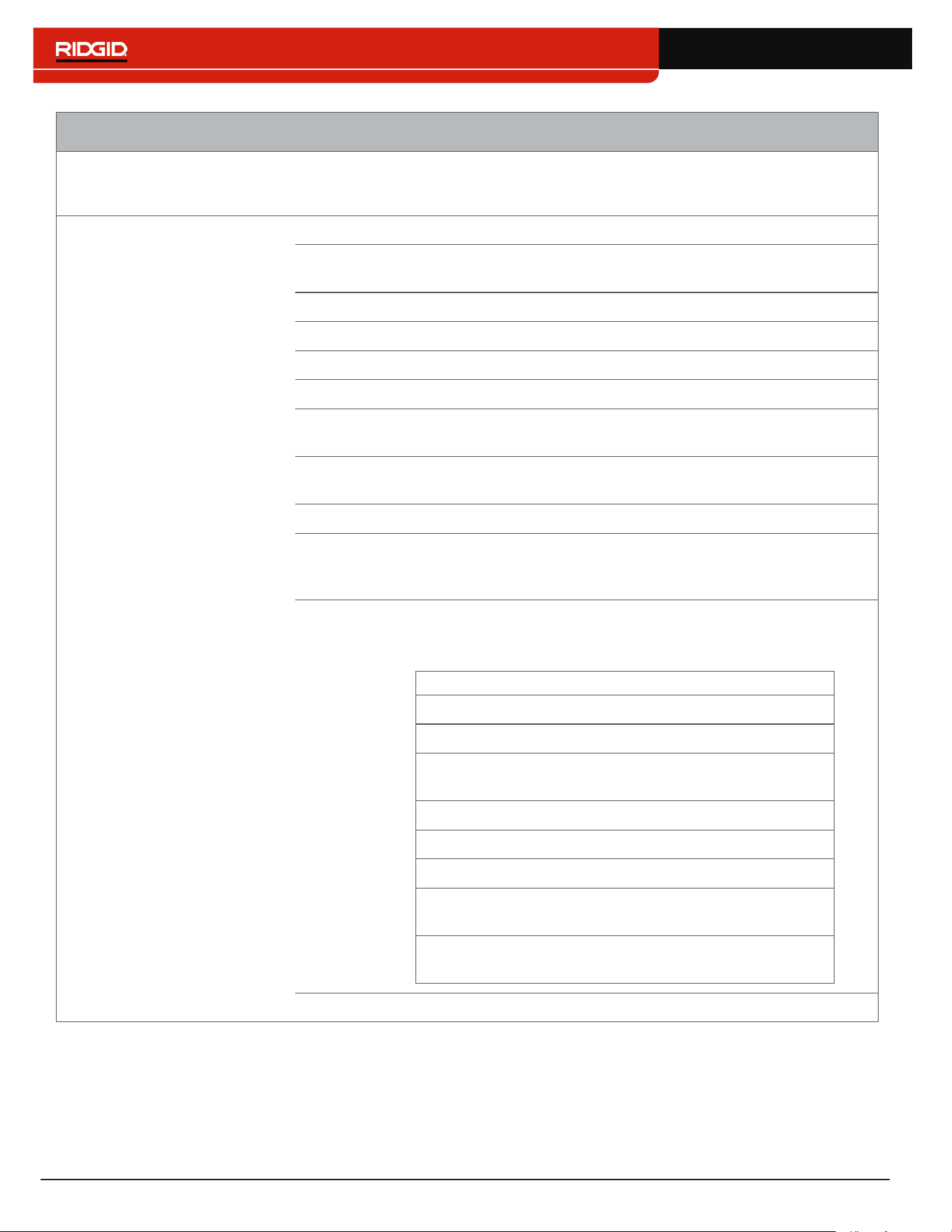
62 – English
Data Logging Abbreviations
Main
Menu
Header
String
Identifier
SeekTech
Grouping
Identifier
Data
Abbreviation
Description
LCD $SEEKT LCD
DSIG The magnitude of the signal received by the SR‑24�
PROX
The number representing the nearness of the target line to the
SR‑24�
GRAD The gradient offset in pixels�
FUZ The value determining the fuzziness of the line being displayed�
DEP The depth for the target line in millimeters (mm)�
COA The current (mA) or the angle of the signal received by the SR‑24�
FREQ
The current frequency filter and the type of frequency: narrow
band or broadband�
TRAC
The locating mode (Sonde, Active Line Trace, Passive Power, or
Passive Radio Frequency)�
BAT The level of battery remaining in levels (0‑7)�
LCOR
The line coordinates (x1, y1, x2, y2) in pixels� Sonde pole
coordinates (Sx, Sy)� Each coordinate is separated by a semi‑
colon�
SYS
The different system display states (Attenuator, Clipping, Polar
Angle/Current, Backlight on/off, Feet/Meters, GPS Lock Status, or
Line/Current Suppression based on Depth)�
Bit(s) Description
0 Attenuator State (0=Off, 1=On)
1 ADC Clipping Status (0=Not Clipping, 1=Clipping)
2
Polar Angle or Current Value in COA (0=Polar,
1=Current)
3 Backlight States (0=Off, 1=On)
4 Feet/Meter State (0=Feet, 1=Meter)
5 GPS Lock Status (0=No Lock, 1=Lock)
6
Whether to show Polar Angle or Current (0=Don’t
Show, 1=Show)
7‑ 8
Sonde Zoom Mode (0=No Zoom, 1=Zoom1,
2=Zoom2)
GPSE The estimated GPS position error in meters (m)�

English – 63
Data Logging Abbreviations
Main
Menu
Header
String
Identifier
SeekTech
Grouping
Identifier
Data
Abbreviation
Description
GPS $GP None
GGA NMEA: Global Positioning System Fix Data
GLL NMEA: Geographical Position, latitude/longitude
GSV NMEA: GPS Satellites in View
GSA NMEA: GPS DOP and Active Satellites
VTG NMEA: Track Made Good and Ground Speed
ZDA NMEA: Date and Time
Note: For information about NMEA GPS codes, visit www.nmea.org.

Printed in USA 2017/12/27
748-024-519-EN-0A Rev D
© 2017 Ridge Tool Company� All rights reserved�
Every effort has been made to ensure that the information in this manual is accurate� Ridge Tool Company and its affiliates
reserve the right to change the specifications of the hardware, software, or both as described in this manual without notice�
Visit www�RIDGID�com for current updates and supplemental information pertaining to this product� Due to product devel‑
opment, the photos and other presentations specified in this manual may differ from the actual product�
RIDGID and the RIDGID logo are trademarks of Ridge Tool Company, registered in the USA and other countries� All other
registered and unregistered trademarks and logos mentioned herein are the property of their respective owners� Mention
of third‑party products is for informational purposes only and constitutes neither an endorsement nor a recommendation�
iPad, iPhone, and iPod touch are trademarks of Apple Inc�, registered in the USA and other countries� “Made for iPod,”
“Made for iPhone,” and “Made for iPad” mean that an electronic accessory has been designed to connect specifically to
iPod, iPhone, or iPad respectively, and has been certified by the developer to meet Apple performance standards� Apple is
not responsible for the operation of this device or its compliance with safety and regulatory standards� Please note that the
use of this accessory with iPod, iPhone, or iPad may affect wireless performance�
The Bluetooth word mark and logos are owned by the Bluetooth SIG, Inc�
R
idge Tool Company
40
0 Clark Street
E
lyria, Ohio 44035-6001
U
SA
1
-800-474-3443
Ridge Tool Europ
e
0
284 dlevnevohruhcS
n
ediurT-tniS 0083
m
uigleB
+32 (0)11 598 62
0
WWW.RIDGID.COM