

GTS 8XX Traffic System
Instructions for Continued Airworthiness
as installed in
_____________________________
(Make and Model Airplane)
Reg. No.____________ S/N_______________
Dwg. Number:
190-00993-01 Rev. 3
Garmin International, Inc.
1200 E. 151st Street
Olathe, Kansas 66062 USA
Record of Revision
Rev.
Date
Description of Change
1
24-Nov-2009
Initial Release
2
29-Oct-2010
Corrected referenced part numbers and added coaxial cable check after
a lightning strike.
3
June 13, 2012
Removed “later FAA approved revisions”; added info re: coaxial cable
rework; added requirement for milli-ohm meter for electrical bonding
testing.

GTS 8XX Traffic System 190-00993-01 Rev. 3
Instructions for Continued Airworthiness Page 2 of 12
TABLE OF CONTENTS
1. INTRODUCTION ................................................................................................................... 3
1.1 Purpose ................................................................................................................. 3
1.2 Scope .................................................................................................................... 3
1.3 Document Control ................................................................................................. 3
1.4 Permission to Use Certain Documents ................................................................. 3
1.5 Definitions ............................................................................................................. 3
2. AIRWORTHINESS LIMITATIONS SECTION ....................................................................... 4
3. INSTRUCTIONS FOR CONTINUED AIRWORTHINESS .................................................... 4
3.1 Introduction ........................................................................................................... 4
3.2 Description of Alteration ........................................................................................ 5
3.3 Control, Operating Information ............................................................................. 5
3.4 Servicing Information ............................................................................................ 5
3.5 Periodic Maintenance ........................................................................................... 5
3.6 Troubleshooting Information ................................................................................. 7
3.7 Removal and Replacement Information ............................................................... 7
3.8 Diagrams............................................................................................................... 8
3.9 Special Inspection Requirements ......................................................................... 8
3.10 Application of Protective Treatments .................................................................... 8
3.11 Data Relative to Structural Fasteners ................................................................... 8
3.12 Special Tools ........................................................................................................ 8
3.13 Additional Instructions ........................................................................................... 8
3.14 Overhaul Period .................................................................................................... 8
3.15 ICA Revision and Distribution ............................................................................... 9
3.16 Assistance............................................................................................................. 9
3.17 Implementation and Record Keeping ................................................................... 9
APPENDIX A - EQUIPMENT LOCATION AND WIRE ROUTING .............................................. 10

GTS 8XX Traffic System 190-00993-01 Rev. 3
Instructions for Continued Airworthiness Page 3 of 12
1. INTRODUCTION
1.1 Purpose
This document is designed for use by the installing agency of the Garmin GTS 8XX Traffic System as
Instructions for Continued Airworthiness in response to 14 CFR § 23.1529, and Part 23 Appendix G. This
ICA includes information required by the operator to adequately maintain the Garmin GTS 8XX Traffic
system installed under Approved Model List (AML) STC.
1.2 Scope
This document identifies the Instructions for Continued Airworthiness for the modification of the aircraft
for installation of the Garmin GTS 8XX Traffic System installed under Approved Model List (AML) STC.
1.3 Document Control
This document shall be released, archived, and controlled in accordance with the Garmin document
control system. When this document is revised, refer to Section 3.15 for information on how to gain FAA
acceptance or approval and how to notify customers of changes.
1.4 Permission to Use Certain Documents
Permission is granted to any corporation or person applying for approval of a Garmin GTS 8XX Traffic
System to use and reference appropriate STC documents to accomplish the Instructions for Continued
Airworthiness and show compliance with STC engineering data. This permission does not construe
suitability of the documents. It is the responsibility of the applicant to determine the suitability of the
documents for the ICA.
1.5 Definitions
The following terminology is used within this document:
1) ACO: Aircraft Certification Office
2) AEG: Aircraft Evaluation Group
3) BIT: Built-In Test
4) CFR: Code of Federal Regulations
5) FAA: Federal Aviation Administration
6) ICA: Instructions for Continued Airworthiness
7) LRU: Line Replaceable Unit (GTS computer, Antenna, or PA/LNA)
8) MFD: Multi-Function Display
9) PMI: Principal Maintenance Inspector
10) STC: Supplemental Type Certificate
11) TAS: Traffic Advisory System
12) TCAS: Traffic Alert and Collision Avoidance System

GTS 8XX Traffic System 190-00993-01 Rev. 3
Instructions for Continued Airworthiness Page 4 of 12
2. AIRWORTHINESS LIMITATIONS SECTION
There are no additional Airworthiness Limitations as defined in 14 CFR § 23, Appendix G. G23.4 that
result from this modification.
The Airworthiness Limitations section is FAA approved and specifies maintenance required under
§§43.16 and 91.403 of the Federal Aviation Regulations unless an alternative program has been FAA
approved.
3. INSTRUCTIONS FOR CONTINUED AIRWORTHINESS
3.1 Introduction
Content, Scope, Purpose and Arrangement:
This document identifies the Instructions for Continued
Airworthiness for the modification of the aircraft by
installation of the Garmin GTS 8XX Traffic System.
Applicability:
Applies to aircraft altered by installation of the Garmin
GTS 8XX Traffic System.
Definition of Abbreviations:
See Section 1.5
Precautions:
None
Units of measurement:
None
Referenced publications:
Garmin 190-00993-00 Rev. 5, “GTS 8XX AML STC
Installation Manual Part 1: Overview and Limitations”,
or later revision
Garmin 190-00993-04 Rev. 5, “GTS 8XX AML STC
Installation Manual Part 2: Mechanical Installation”, or
later revision
Garmin 190-00993-05 Rev. 5, “GTS 8XX AML STC
Installation Manual Part 3: Electrical Installation”, or
later revision
Garmin 190-00993-03 Rev. 5, “GTS 8XX AML STC
Installation Manual Part 4: Configuration, Checkout
and Maintenance”, or later revision
Retention:
This document, or the information contained within, will
be included in the aircraft’s permanent records.
The GTS 8XX AML STC Installation Manual is referenced extensively throughout this document. To
improve readability references to specific parts of the installation manual are abbreviated as follows:
Reference
Document Title
Part Number
GTS-IM1
GTS 8XX AML STC Installation Manual Part 1: Overview and Limitations
190-00993-00
GTS-IM2
GTS 8XX AML STC Installation Manual Part 2: Mechanical Installation
190-00993-04
GTS-IM3
GTS 8XX AML STC Installation Manual Part 3: Electrical Installation
190-00993-05

GTS 8XX Traffic System 190-00993-01 Rev. 3
Instructions for Continued Airworthiness Page 5 of 12
Reference
Document Title
Part Number
GTS-IM4
GTS 8XX AML STC Installation Manual Part 4: Configuration, Checkout
and Maintenance
190-00993-03
3.2 Description of Alteration
The Garmin GTS 8XX Traffic System consists of one traffic unit (GTS 800, GTS 820 or GTS 850), one or
two directional antennas (GA 58) and for the high power systems, a low-noise amplifier (GPA 65).
Traffic units are distinguished as follows:
- GTS 800: Traffic Advisory System (TAS) with 40 watts transmit power
- GTS 820: Traffic Advisory System (TAS) with 250 watts transmit power
- GTS 850: Traffic Collision Avoidance System (TCAS I) with 250 watts transmit power.
The GTS 820 and GTS 850 traffic units require installation of the GPA 65: Power Amplifier/Low-Noise
Amplifier (PA/LNA).
A GTS 8XX traffic system requires installation of one top-mounted directional antenna (GA 58) and
allows for connection to an optional bottom-mounted antenna (GA 58 directional or C74c approved omni-
directional).
Refer to the Appendix of this document or the GTS 8XX System Configuration and Checkout Log
retained in the aircraft permanent records for a list of which GTX 8XX and antennas are installed.
Installation of the Garmin GTS8XX Traffic system, specific for the aircraft installation, is documented in
GTS-IM2 (190-00993-04) and GTS-IM3 (190-00993-05).
3.3 Control, Operating Information
See GTS-IM1 (190-00993-00) for a system description and system limitations. The GTS 8XX Traffic
system does not have a direct pilot interface. Refer to GTS-IM3 (190-00993-05), Appendix A for a list of
display equipment that can be interfaced to the GTS 8XX. Pilots Guide information published for those
displays will provide operating information.
See GTS-IM4 (190-00993-03), Section 3 for checkout and self-test information.
3.4 Servicing Information
None. In the event of system failure, troubleshoot the GTS 8XX Traffic System in accordance with
Section 3.6 Troubleshooting Information below.
3.5 Periodic Maintenance
All GTS 8XX Traffic System LRUs are designed to detect internal failures. A thorough self-test is
executed automatically upon application of power to the units, and built-in tests are continuously
executed. Detected errors are indicated on the cockpit MFD used to display traffic information from the
GTS 8XX. Detected errors are displayed as failure annunciations.
Operation of the GTS 8XX Traffic System is not permitted unless the inspections described in this
section have been completed within time intervals prescribed in Table 1 below.

GTS 8XX Traffic System 190-00993-01 Rev. 3
Instructions for Continued Airworthiness Page 6 of 12
Table 1 - Maintenance Intervals
Item
Description/Procedure
Interval
Equipment Removal
& Replacement
Removal and replacement of:
GTS 8XX Traffic Unit, (one of the following)
GTS 800 TAS Unit (low power)
GTS 820 TAS Unit (high power)
GTS 850 TCAS I Unit (high power
GPA 65 Antenna Amplifier (for high power installations)
GA 58 Traffic Antenna(s) (top-mounted antenna, plus
optional bottom-mounted antenna)
Removal and replacement instructions are contained in
Section 3 of this document and in GTS-IM4 (190-00993-
03), Section 4.
On Condition
Equipment Visual
Inspection
Conduct a visual inspection on the GTS 8XX traffic unit and
its wire harness to insure continued installation integrity.
1. Inspect the GTS 8XX unit for security of attachment
2. Inspect condition of wiring, routing, and
attachment/clamping.
24 Calendar
Months
Antenna Visual
Inspection
Conduct a visual inspect on the GA 58 antenna(s) for proper
sealing and attachment.
In the event attachment is not secure, re-attach antenna and
complete the Electrical Bonding Test [see below for
instructions].
In the event antenna seal shows signs of damage or
decomposition, complete the Electrical Bonding Test [see
below for instructions] and re-seal antenna.
24 Calendar
Months
Antenna Visual
Inspection -
Suspected lightning
strike
In the event of a suspected or actual lightning strike to the
aircraft, the GA 58 Antenna(s) and its associated
installation shall be inspected.
If the GA58 Antenna was struck by lightning then the
antenna and the surrounding installation shall be
inspected to ensure that there is no structural damage
around the areas where lightning may have attached.
At the antenna end ensure there is no damage to the
connectors on the antenna and on the coaxial cable.
Ensure that the coaxial cable connectors are securely
attached to the antenna connectors.
Execute the system checkout procedure identified in GTS-
IM4 (190-00993-03), Section 3, to ensure the system is
operating correctly.
Suspected or
actual lightning
strike

GTS 8XX Traffic System 190-00993-01 Rev. 3
Instructions for Continued Airworthiness Page 7 of 12
Item
Description/Procedure
Interval
Electrical Bonding
Test
An electrical bonding test must be performed on GA 58
Antenna(s) installed by this STC.
For top-mounted GA 58 Antenna:
1. Gain access to the antenna installation.
2. Disconnect all four coaxial cable antenna connectors
(GA 58 antenna, connectors P1-P4).
3. Measure the resistance between the body of the
connector on the antenna base and a nearby
exposed portion of aircraft structure (example:
exposed rivet on fuselage stringer).
4. Verify the resistance is equal to or less than 10
milliohms.
5. Reconnect all four antenna connectors ensuring each
connector is secured.
Repeat for optional bottom-mounted GA 58 Antenna.
In the event of bonding test failure, remove antenna, clean
and re-attach using unit replacement procedures in GTS-
IM4 (190-00993-03), Section 4. The fresh attachment
should yield resistance less than or equal to 2.5
milliohms.
Every 2000
flight hours or
ten (10) years,
whichever is
first
3.6 Troubleshooting Information
If error indications are displayed for the GTS 8XX Traffic system, consult GTS-IM4 (190-00993-03),
Section 5, Troubleshooting. Refer to the GTS 8XX System Configuration and Checkout Log retained in
the aircraft permanent records for a list of the interfaced equipment and system configuration data
(example log provided in GTS-IM4 (190-00993-03)).
3.7 Removal and Replacement Information
If any GTS 8XX LRUs are removed and reinstalled, verify that the LRU unit power-up self-test sequence
is successfully completed and no failure messages are annunciated for the GTS 8XX Traffic system.
See the unit replacement procedures in GTS-IM4 (190-00993-03), Section 4.
If any work has been done on the aircraft that could affect the system wiring, antenna cable, or any
interconnected equipment, verify the GTS 8XX system unit power-up self-test sequence is successfully
completed and no failure messages are annunciated for the GTS 8XX Traffic system.
In the event that an individual coaxial cable assembly requires rework, refer to GTS-IM4 (190-00993-03),
Section 6.1 for instructions.
Refer to Appendix A of this document or the GTS 8XX System Configuration and Checkout Log retained
in the aircraft permanent records for GTX 8XX equipment and antenna location.
Refer to GTS-IM4 (190-00993-03), Section 4 for particular LRU and antenna removal/installation
procedures and special handling precautions.

GTS 8XX Traffic System 190-00993-01 Rev. 3
Instructions for Continued Airworthiness Page 8 of 12
3.8 Diagrams
Aircraft specific LRU locations and wire routing diagram are contained in Appendix A of this document.
GTS-IM1 (190-00993-00), Appendix A provides diagrams that indicate lightning zones to guide antenna
installation. GTS-IM2 (190-00993-04), Appendix C and Appendix D provide diagrams showing sample
installation for LRU locations. GTS-IM3 (190-00993-05), Appendix C provides point-to-point wiring
diagrams for GTS 8XX LRUs and interfaced equipment.
Refer to the GTS 8XX System Configuration and Checkout Log retained in the aircraft permanent
records for a list of the interfaced equipment and unit configuration data (example log provided in GTS-
IM4 (190-00993-03)).
3.9 Special Inspection Requirements
There are no special inspection techniques required.
3.10 Application of Protective Treatments
Data relative to protective treatments, such as primers or sealants and installation requirements can be
found in GTS-IM2 (190-00993-04), Section 2.
3.11 Data Relative to Structural Fasteners
Data relative to structural fasteners, such as type, torque, and installation requirements can be found in
GTS-IM2 (190-00993-04), Section 2.
3.12 Special Tools
Refer to GTS-IM3 (190-00993-05), Section 2.1 for a list of electrical installation tools required.
For electrical bonding testing, a milli-ohm meter is required.
In addition to electrical tools GTS-IM1 (190-00993-00), Section 2.4.3 identifiers a ramp tester tool to aid
system checkout and GTS-IM4 (190-00993-03), Section 2.2 identifies the GTS 8XX Install Tool (a
software tool) used to configure the system during installation.
No other special tools are needed.
3.13 Additional Instructions
There are no Commuter Class airplanes on the AML at this time.
There are no additional ICA instructions for this STC.
3.14 Overhaul Period
The system does not require overhaul at a specific time period. Power on self-test and continuous BIT
will monitor the health of the GTS 8XX system. If any LRU indicates an internal failure, the unit may be
removed and replaced. See GTS-IM4 (190-00993-03), Section 5 for Troubleshooting information.

GTS 8XX Traffic System 190-00993-01 Rev. 3
Instructions for Continued Airworthiness Page 9 of 12
3.15 ICA Revision and Distribution
To revise this ICA, Garmin will follow the Garmin ODA procedures manual SOP-055/ACP-016 for
Instructions for Continued Airworthiness. The latest revision of this ICA document is available on the
Garmin website (www.garmin.com). A Garmin Service Bulletin describing ICA revision will be sent to
Garmin dealers if a revision is determined to be significant.
3.16 Assistance
Flight Standards Inspectors or the certificate holder’s PMI have the required resources to respond to
questions regarding this ICA. In addition, the customer may refer questions regarding this equipment and
its installation to the manufacturer, Garmin. Garmin customer assistance may be contacted during
normal business hours via telephone 913-397-8200 or email from the Garmin web site at
www.garmin.com.
3.17 Implementation and Record Keeping
Modification of an aircraft by this Supplemental Type Certificate obligates the aircraft operator to include
the maintenance information provided by this document in the operator’s aircraft maintenance manual
and/or the operator’s aircraft scheduled maintenance program.

GTS 8XX Traffic System 190-00993-01 Rev. 3
Instructions for Continued Airworthiness Page 10 of 12
APPENDIX A - EQUIPMENT LOCATION AND WIRE ROUTING
A.1 LRU LOCATIONS
The following table describes the location of the applicable GTS 8XX Traffic Unit (identify the traffic unit
installed):
LRU
LRU included
in this
installation?
Description of Location
GTS 800 TAS Unit
Yes No
GTS 820 TAS Unit
Yes No
GTS 850 TCAS I Unit
Yes No
The following table describes the location of the GA 58 Directional Antenna (identify location for top-
mounted antenna and optional bottom-mounted antenna):
LRU
LRU included
in this
installation?
Description of Location
GA 58 Antenna #1
Yes No
GA 58 Antenna #2
(Optional)
Yes No
The following table describes the location of the GPA 65 PA/LNA amplifier unit (installed with either a
GTS 820 or GTS 850 traffic unit):
LRU
LRU included
in this
installation?
Description of Location
GPA 65 PA/LNA
Yes No
GTS 8XX Traffic System 190-00993-01 Rev. 3
Instructions for Continued Airworthiness Page 11 of 12
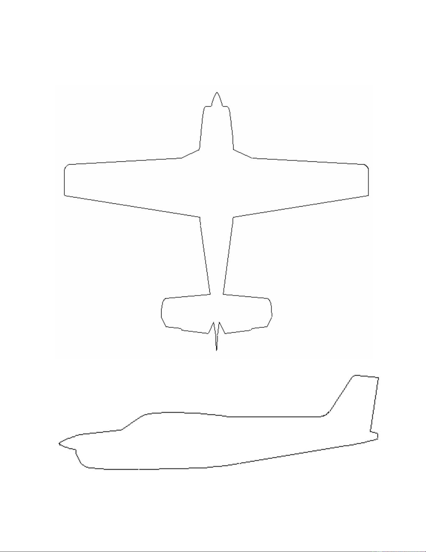
A.2 WIRE ROUTING – SINGLE-ENGINE
The following diagram depicts approximate location of LRUs and antenna(s) along with the wire routing
for the GTS 8XX LRUs throughout the aircraft structure for a single-engine aircraft:
GTS 8XX Traffic System 190-00993-01 Rev. 3
Instructions for Continued Airworthiness Page 12 of 12
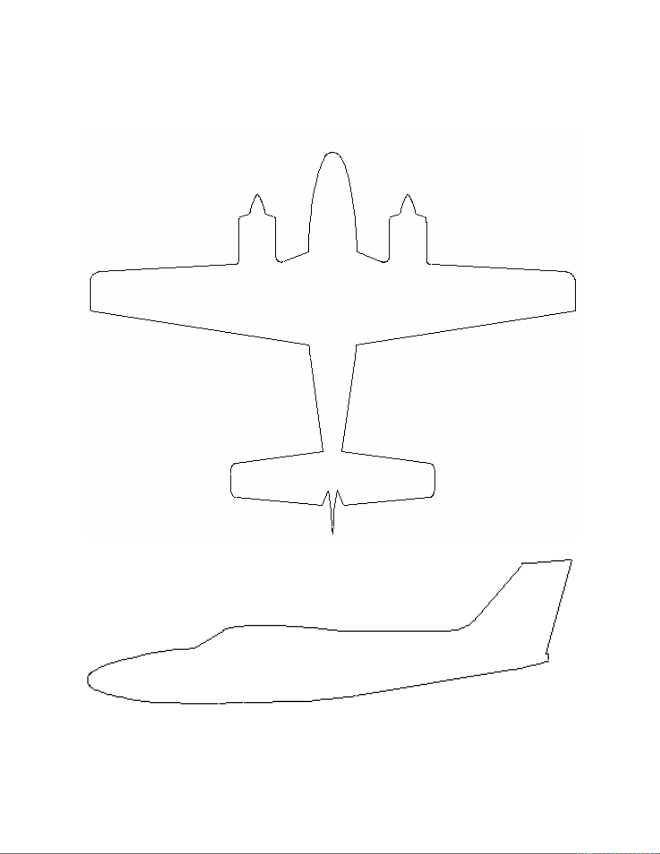
A.3 WIRE ROUTING – TWIN-ENGINE
The following diagram depicts approximate location of LRUs and antenna(s) along with the wire routing
for the GTS 8XX LRUs throughout the aircraft structure for a twin-engine aircraft: