
CSG-7410
WARNING
Read the instructions carefully and follow the rules for safe
operation.
Failure to do so could result in serious injury.
OPERATOR’S MANUAL
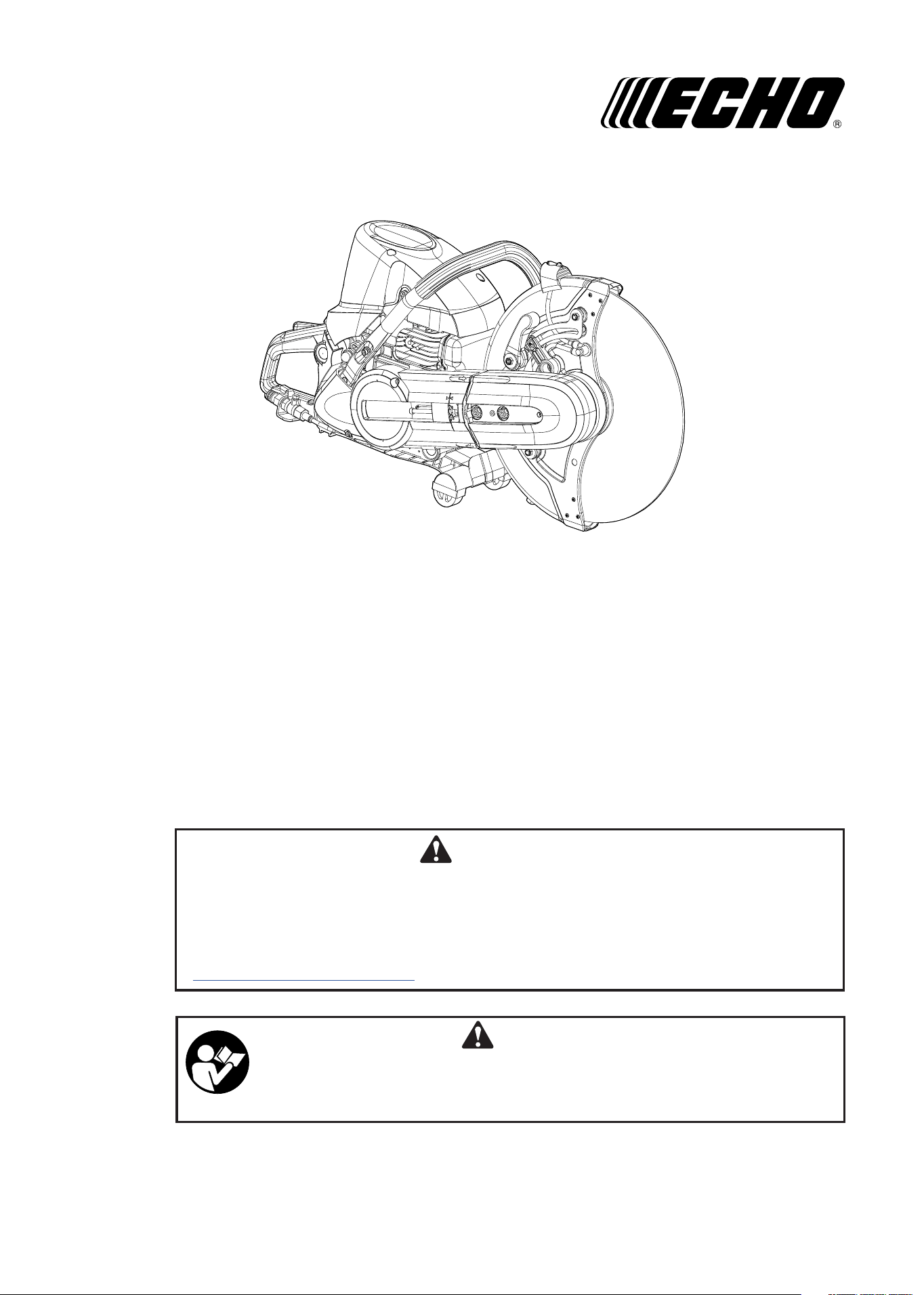
ENGINE CUT-OFF SAW
X7503954100
ECHO, INCORPORATED
400 Oakwood Road, Lake Zurich, Illinois 60047-1564
Phone : 847-540-8400
Printed in USA
WARNING
The engine exhaust from this product contains chemicals known to the
State of California to cause cancer, birth defects or other reproductive
harm.
Cancer and Reproductive Harm
www.P65Warnings.ca.gov
2
CSG-7410
INTRODUCTION
CONTENTS
WARNING
Some dust created by power sanding, saw-
ing, grinding, drilling, and other construc-
tion activities contains chemicals known to
the State of California to cause cancer, birth
defects or other reproductive harm. Some
examples of these chemicals are:
• Lead from lead-based paints,
• Crystalline silica from bricks and cement
and other masonry products, and
• Arsenic and chromium from chemically
treated lumber.
Your risk from these exposures varies,
depending on how often you do this type
of work. To reduce your exposure to these
chemicals: work in a well ventilated area,
and work with approved safety equipment,
such as those dust masks that are specially
designed to filter out microscopic particles.
The ECHO model CSG-7410 Engine Cut-off saw is
a high-performance gasoline-powered tool de-
signed for use with a recommended 350 x 4.7 x 20
mm (14 in. x 6/32 in. x 25/32 in.) abrasive wheel. A
water-flush attachment is available for dust control.
Use only ECHO’s wheels or other wheels having
a minimum spindle speed rating of 3820 rpm or
higher.
This manual provides the information necessary for
assembly, operation and maintenance of the cut-
off saw as well as the wheels available for it. It is
important that you follow this information carefully.
WARNING
Improper use or care of this unit, or failure to
wear proper protection can result in serious
injury.
Read the rules for safe operation and instruc-
tions in this manual.
Wear eye and hearing protection and a dust
mask when operating.
Breathing in asbestos fibers can pose a
serious health risk and may cause severe
or fatal respiratory diseases such as lung
cancer. Do not use your engine cut-off saw to
cut, damage, or disturb asbestos or products
using asbestos in any form. If you believe
you might be cutting asbestos, contact your
employer immediately.
Introduction ............................................ 2
Symbols and Signs ................................ 3
Packing List ........................................... 5
Nomenclature of Parts ........................... 6
Operator Safety Precautions ................. 8
Operator Safety ..................................... 10
Abrasive Wheel Types and Uses ........... 12
Preparation for Use ............................... 15
Fuel and Lubricant ................................. 18
Emission Data ....................................... 20
Operation ............................................... 20
Cutting Instruction ................................. 23
Maintenance and Care .......................... 24
Troubleshooting ..................................... 31
Storage After Use .................................. 32
Technical Data ....................................... 34
Warranty Registration Sheet .................. 34
Notes ..................................................... 35
Specifications, descriptions and illustrations in this manual were accurate at the time of publication, and
are subject to change without notice. Illustrations may include optional equipment and accessories, and
may not include all standard equipment.
Copyright
©
2018
All Rights Reserved.
3
CSG-7410
SYMBOLS AND SIGNS
Decals
WARNING
The safety alert symbol accompanied by
the word “WARNING” calls attention to an
act or condition which CAN lead to serious
personal injury or death if not avoided.
CAUTION
The safety alert symbol accompanied by
the word “CAUTION” calls attention to an
act or condition which may lead to minor or
moderate personal injury if not avoided.
NOTE
This enclosed message provides tips for use,
care and maintenance of the unit.
IMPORTANT
The enclosed message provides information
necessary for the protection of the unit.
DANGER
The safety alert symbol accompanied by
the word “DANGER” calls attention to an
act or condition which WILL lead to serious
personal injury or death if not avoided.
CIRCLE AND SLASH SYMBOL
This symbol means the specific action
shown is prohibited. Ignoring these
prohibitions can result in serious or
fatal injury.
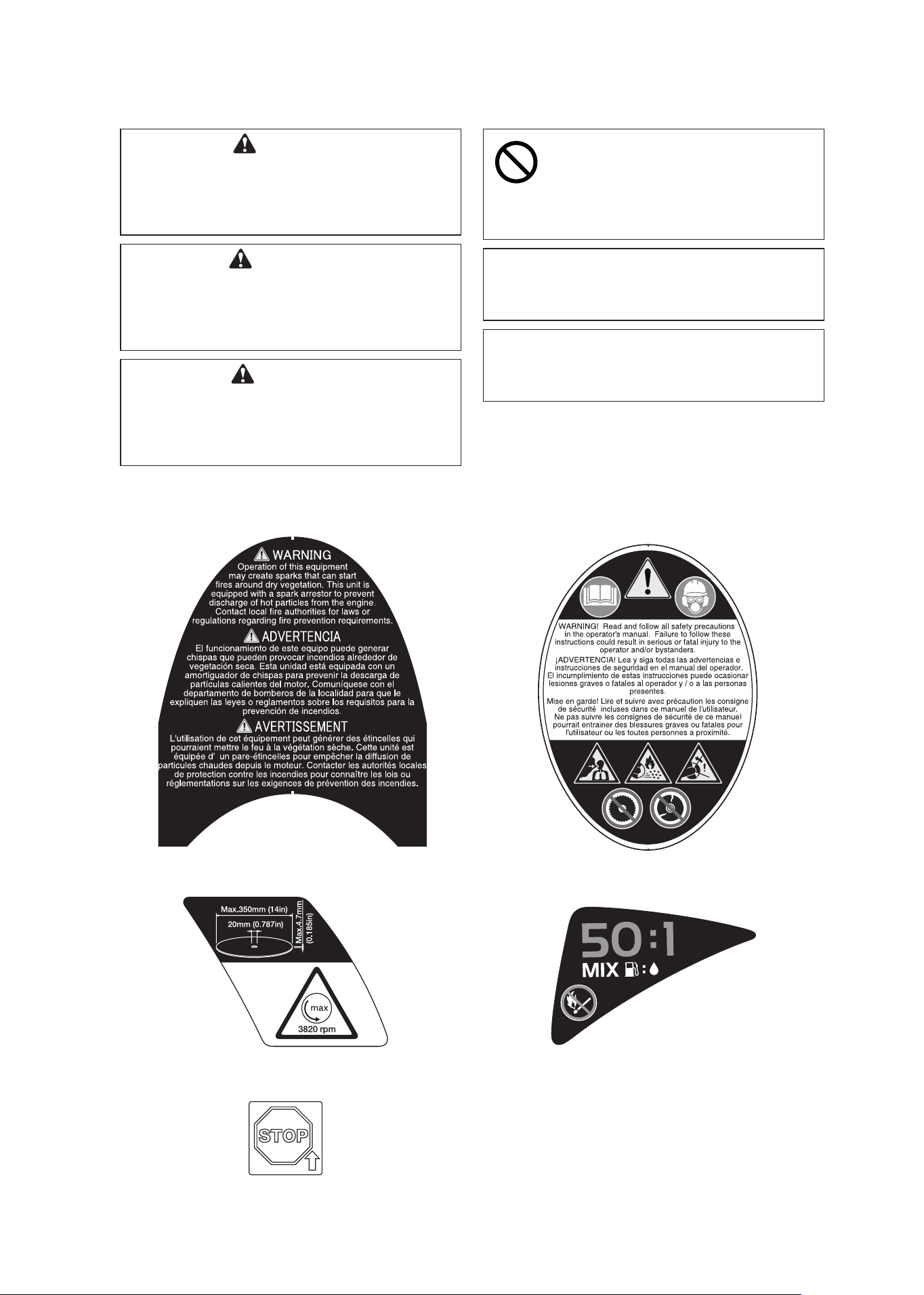
Locate the safety decals on your unit. The complete
unit illustration found in the “NOMENCLATURE OF
PARTS” section will help you locate them.
Make sure the decal is legible and that you
understand and follow the instructions on it. If a
decal cannot be read, a new one can be ordered
from your ECHO dealer.
4
CSG-7410
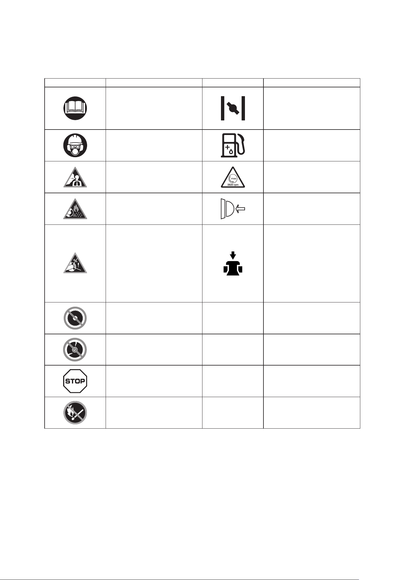
SYMBOL FORM
Symbol form/shape Symbol description/application Symbol form/shape Symbol description/application
WARNING!!
Read and follow all safety
precaution in the Operator's
Manual. Failure to follow
instructions could result in
serious personal injury.
Choke control
Always wear an ear muffler,
a dust proof mask, goggles
and a helmet when operating
this machine. (ANSI Z87.1)
Oil and gasoline mixture
Do not run the engine
indoors, or where there is
poor ventilation.
Wheel rorating direction Max
spindle speed
Cutting may cause sparks
from the cut-off wheel. Make
sure there is no flammable
substance nearby.
Purge pump
Kickback may force the
cutting-off wheel up and
back toward the operator
with a lightning-fast reaction.
Kickback can occur
whenever the upper-half of
the cutting-off wheel touches
an object while operating the
machine.
Decompression device
Usage of saw blades not
permitted.
L
Carburetor adjustment
- Low speed mixture
Make sure there are no
breaks,cracks or warps.
H
Carburetor adjustment
- High speed mixture
Emergency stop
T
Carburetor adjustment
- Idle speed
Keep away from fire.
5
CSG-7410
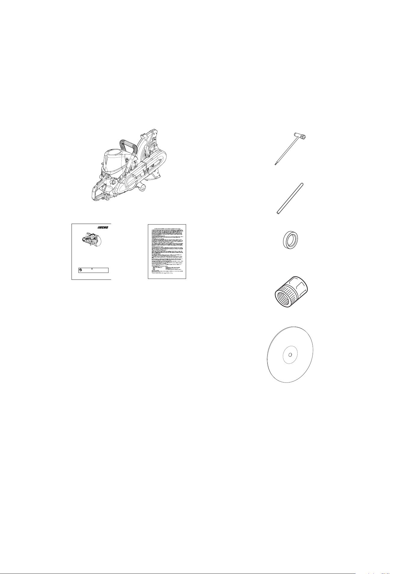
PACKING LIST
The ECHO product you purchased has been
factory pre-assembled for your convenience.
Due to packaging restrictions, wheel installation
and other assembly may be necessary.
After opening the carton, check for damage.
Immediately notify your retailer or ECHO dealer of
damaged or missing parts.
Use the packing list to check for missing parts.
13 x 19 mm T-wrench
Operator's manual
ECHO engine cut-off saw
Warranty sheet
• •
• •
• •
• •
• •
Coupler
Adapter (25.4 mm)
CSG-7410
WARNING
Read the instructions carefully and follow the rules for safe
operation.
Failure to do so could result in serious injury.
OPERATOR’S MANUAL
ENGINE CUT-OFF SAW
X750 395-410 0
ECHO, INCORPORATED
400 Oakwood Road, Lake Zurich, Illinois 60047-1564
Phone : 847-540-8400
Printed in USA
Bar tool
Wheel
6
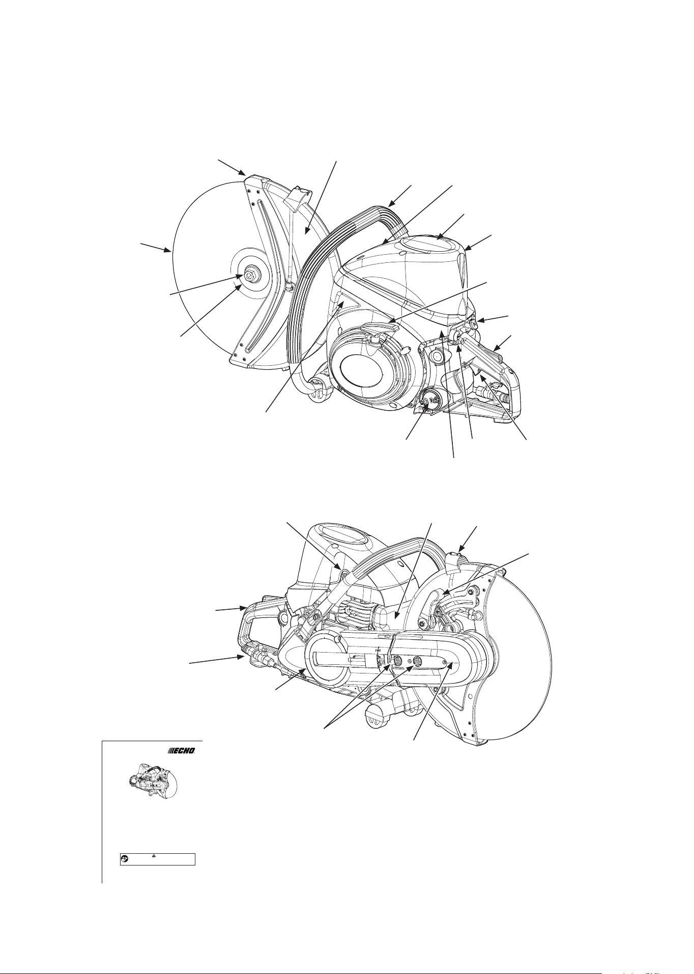
CSG-7410
NOMENCLATURE OF PARTS
3
4
5
6
7
8
9
10
11
12
13
14
2
15
16
17
18
19
21
20
22
23
CSG-7410
WARNING
Read the instructions carefully and follow the rules for safe
operation.
Failure to do so could result in serious injury.
OPERATOR’S MANUAL
ENGINE CUT-OFF SAW
X750 395-410 0
ECHO, INCORPORATED
400 Oakwood Road, Lake Zurich, Illinois 60047-1564
Phone : 847-540-8400
Printed in USA
1
23
23
23
23

7
CSG-7410
1. Operator's manual - Included with unit.
Read before operation and keep for future
reference to learn proper, safe operating
techniques.
2. Front handle (for the left hand) - Support
handle located at the front of the engine
housing.
3. Wheel guard - A wheel guard which is intend-
ed to protect the operator from wheel con-
tact, and also direct debris away from the
operator.
4. Wheel - Serving as a cutting tool.
5. Wheel mouting bolt - Bolt that secures the
flange.
6. Cutter flange - Part that secures the cutting
wheel.
7. Fuel tank cap - For closing the fuel tank.
8. Momentary stop switch - Button for momen-
tarily shorting ignition voltage, causing the
engine to stop. This is NOT an ON/OFF
Ignition switch.
9. Throttle trigger - Device activated by the
operator’s finger, for controlling the engine
speed.
10. Throttle trigger lockout - A safety lever which
must be depressed before the throttle trigger
can be activated in order to prevent the
accidental operation of the throttle trigger.
11. Choke control knob - Device for enriching the
fuel/air mixture in the carburetor to aid cold
starting. Also activates fast idle throttle latch.
NOMENCLATURE OF PARTS
12. Starter grip - Pull handle slowly until starter
engages then quickly and firmly.
When engine starts, return handle slowly.
Do not let handle snap back or damage to
unit will occur.
13. Air cleaner cover - Covers air cleaner.
14. Rear handle (for the right hand) - Support
handle located towards the rear of the
engine housing.
15. Water kit - Supplies water while cutting to keep
dust from scattering.
16. Clutch cover - Protective belt and clutch when
the engine cut-off saw is in use.
17. Arm mounting bolts - Secures the cut-off saw.
18. Pulley Cover - Protects the belt and pulley.
19. Wheel guard locking knob - For use when
changing the angle of the wheel guard.
20.
Wheel guard knob - Grip and move this knob
when changing the angle of the wheel guard.
21. Spark arrestor muffler - The spark arrestor
muffler controls the exhaust noise and
prevents hot, glowing particles of carbon
from leaving the muffler.
22. Decompression device - Device for lowering
the compression in the cylinder, to aid
starting.
23. Safety labels - Device for lowering the com-
pression in the cylinder, to aid
starting.
8
CSG-7410
Read this engine cut-off saw operator’s manual carefully.
Be sure you understand how to operate this saw properly before you use it.
Establish a training program for engine cut-off saw operators.
Use safety footwear, snug-fitting clothing and protective gloves.
Wear eye, hearing and head protection devices. Use ballistics chaps or pants
when necessary. Clothing of fire-resistant and non-meltable material should
be worn by emergency crews exposed to flames or high heat conditions.
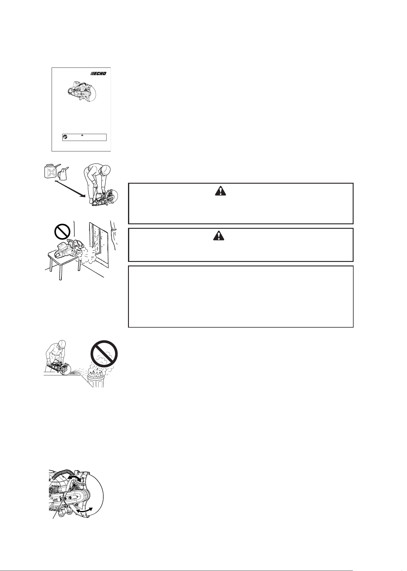
Use caution when handling fuel. Put the fuel tank caps back tightly on both
the fuel container and the saw tank, move at least 3 m (10 ft.) from the
fueling point, and be sure there is no leakage of fuel from the fuel tank cap or
the fuel system before starting the engine. Avoid ignition from sparks.
DANGER
After refuelling, tighten fuel cap firmly and check for leakage.
In case of fuel leakage repair before starting operation since there is
a danger of fire.
WARNING
Do not run the engine indoors, or where there is poor ventilation.
Engine fumes contain deadly poisonous carbon monoxide.
IMPORTANT
Check before every use.
After refuelling, make sure fuel does not leak from around fuel pipe, fuel
grommet or fuel tank cap.
In case of fuel leakage there is a danger of fire. Stop using the machine
immediately and request your dealer to inspect or replace.
It is not permitted to fill fuel above the shoulder level of fuel tank.
Operate this gasoline engine cut-off saw only in well-ventilated areas.
Do not store the unit with fuel in its tank, because a fuel leak could start a
fire.
Do not cause sparks in any area where there are flammable materials.
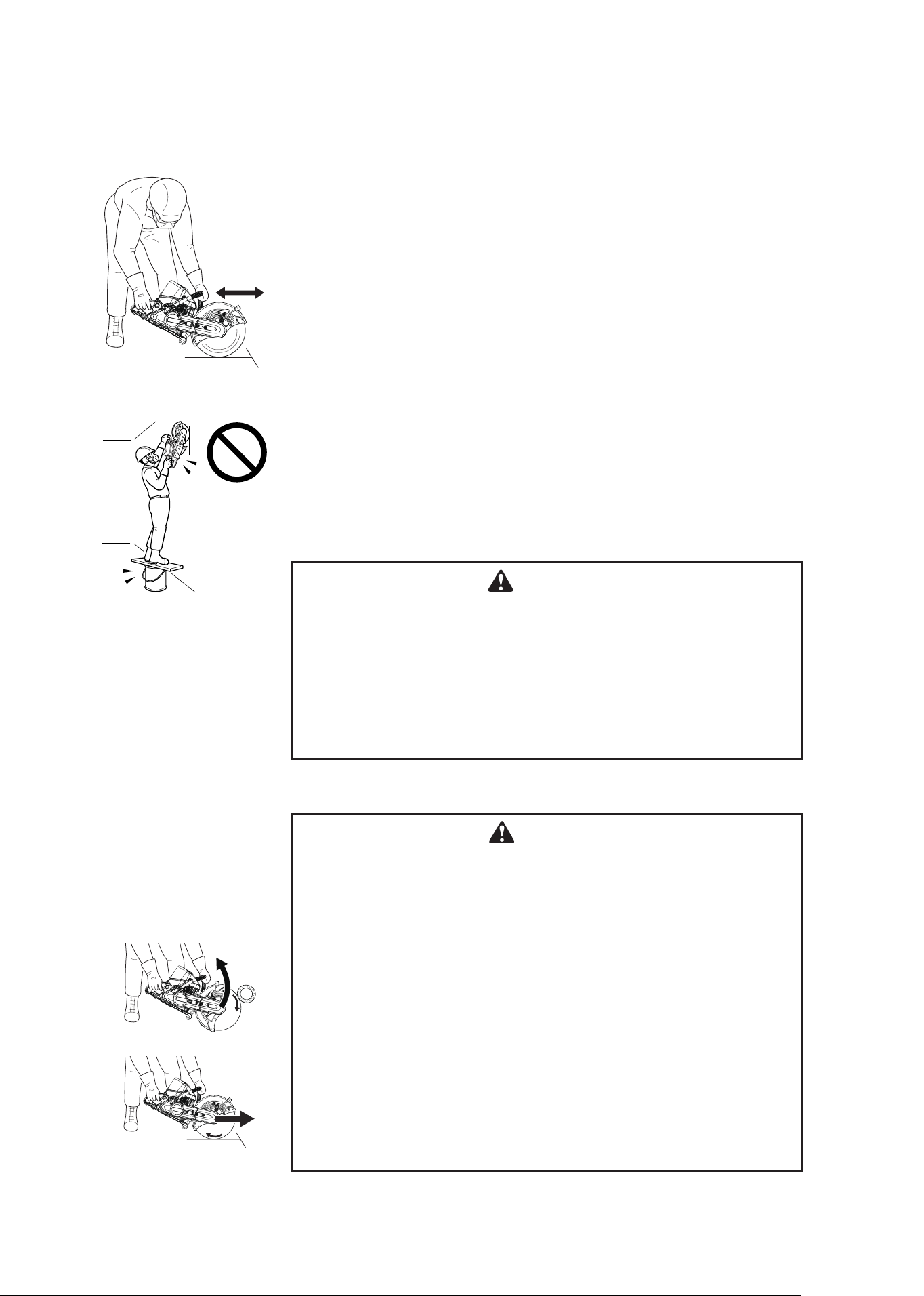
Start the engine cut-off saw on the ground with the cutting wheel completely
in the clear.
Do not drop-start the engine cut-off saw, or start it if the wheel is obstructed
by the ground or any other object.
Do not allow other persons to be closer than 9 m (30 ft.) when you are
starting or cutting with the saw. Bystanders should wear hearing and eye
protection. Do not start cutting unless you have good footing and the work
area is clear.
Do not let someone hold the work you are cutting.
Adjust the wheel guard to a position where the sparks and debris from the
wheel will be thrown away from you. Turn the wheel guard locking knob
counterclockwise, grasp the wheel guard knob and move the wheel guard to
the desired position, slowly release it and secure the wheel guard with the
locking knob. Do not operate if the wheel guard is damaged, missing from
the unit, improperly positioned, or cannot be locked in proper position.
OPERATOR SAFETY PRECAUTIONS
3 m
Adjust Wheel guard
Wheel guard locking knob
CSG-7410
WARNING
Read the instructions carefully and follow the rules for safe
operation.
Failure to do so could result in serious injury.
OPERATOR’S MANUAL
ENGINE CUT-OFF SAW
X750 395-410 0
ECHO, INCORPORATED
400 Oakwood Road, Lake Zurich, Illinois 60047-1564
Phone : 847-540-8400
Printed in USA
9
CSG-7410
Keep a firm grip on the engine cut-off saw with both hands, the right hand
on the rear handle, and the left hand on the front handle when the engine is
running. Use a firm grip with thumbs and fingers encircling the saw handles.
A firm grip will help you to keep control if the saw kickback toward you, or the
thrust of the rotating wheel pulls it away from you. Never operate the engine
cut-off saw with only one hand.
Be careful around electrical cables, sewer and gas lines to avoid cutting
them.
Keep to the left of the saw so that no part of your body is in line with the
cutting wheel. Keep all parts of your body away from the cutting wheel when
the engine is running.
Do all cutting at full throttle. Cutting at less than full speed can damage the
clutch by allowing it to slip. Accelerating from slow to full speed while the
wheel is in cutting contact may cause a violent push or pull reaction resulting
in loss of control.
It will take time for the wheel to coast to a stop after the throttle trigger is
released. Be sure to wait for rotation to stop before releasing your grip on the
saw handles. Always shut off the engine before setting down the saw.
Never leave the engine cut-off saw while the engine is running.
Always carry the saw with the engine stopped and the hot muffler away from
your body. Do not touch a hot muffler, wheel, cylinder cover or cylinder.
Do not touch high voltage parts such as spark plug and spark plug lead.
Remove the wheel from the saw prior to transport or storage. Store wheels
properly to avoid damage from uneven pressure, moisture and extreme
temperatures.
Do not grind on the side of an abrasive engine cut-off saw wheel, or put any
side pressure on the wheel during cutting. Avoid letting the saw tilt or wobble
off line.
Use new, properly qualified wheels of correct diameter, thickness and
mounting hole size. The wheel blotters and the mounting flanges should be
in good condition, and the mounting bolt should be tightened to the proper
torque.
Inspect the wheel carefully for cracks, edge damage and warping before use.
Do not use any wheel that has been dropped.
All adjustment and maintenance instructions in this operator’s manual
should be performed as necessary, and may be done by the saw owner. All
other service or adjustment should be performed only by a qualified ECHO
servicing dealer.
Keep to Left of
Cutting Line
Put no Side
Pressure on
the Wheel
Check for Wheel
Damage
10
CSG-7410
Spectators children and fellow workers must be
warned to come no nearer than 9 m (30 feet) while
the saw is in use. Shut off the saw immediately if
some one moves closer to you than 9 m (30 feet).
Persons working in the area near you should wear
the same protective equipment as the saw operator
if endangered by risky flying debris.
OPERATOR SAFETY
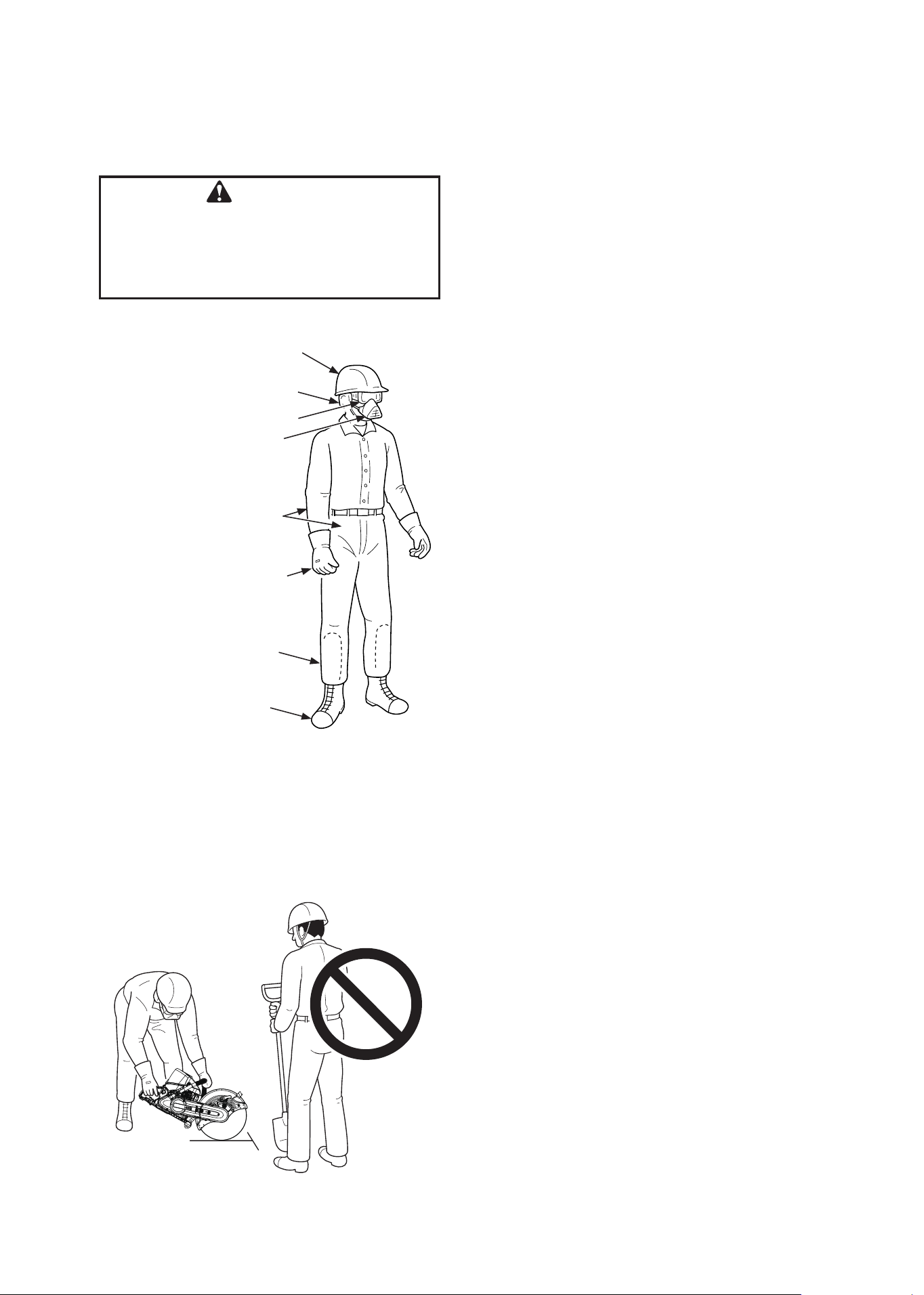
Protective Equipment
WARNING
Engine cut-off saw users risk injury if the
saw is used improperly, and / or safety pre-
cautions are not followed. Protective clothing
and safety gear must be worn when operat-
ing a engine cut-off saw.
You must wear eye protection goggles qualified
to the CE mark or the latest ANSI Standard Z 87.
(Z 87 is stamped on the goggles). These goggles
also must be worn under a face screen if one is
used. A face screen should be worn when there
is a risk from flying debris.
Hearing protection should be worn. (See
“DANGER,” page 23)
Wear a respirator or dust mask (APF10) when
cutting concrete, stone, brick or other materials
where fine dust is produced while cutting. Use
water flush to keep down the dust.
Clothing should be made from fabric containing
natural fibres that resist catching fire and do not
melt. The clothing should cover as much skin
area as possible. Clothing should offer freedom
of movement, but should not be too loose or
baggy. Do not wear ties or jewellery.
Wear heavy duty boots with non-slip soles. The
boots should be high enough for shin protection,
or you should wear chaps for shin protection.
Wear non-slip, heavy duty work gloves to
improve your grip on the saw handles. The
gloves also help to reduce the transmission of
machine vibrations to your hands.
Hard Hat
No Bystanders!
Hearing Protection
Goggles (Z 87)
Dust Mask or Respirator
Trim-Fitting
Protective Clothing
Heavy Duty non-Slip Gloves
Chaps or High Boots
for Spark Protection
Heavy Duty Boots
with non-Slip Soles
Protecting Others
11
CSG-7410
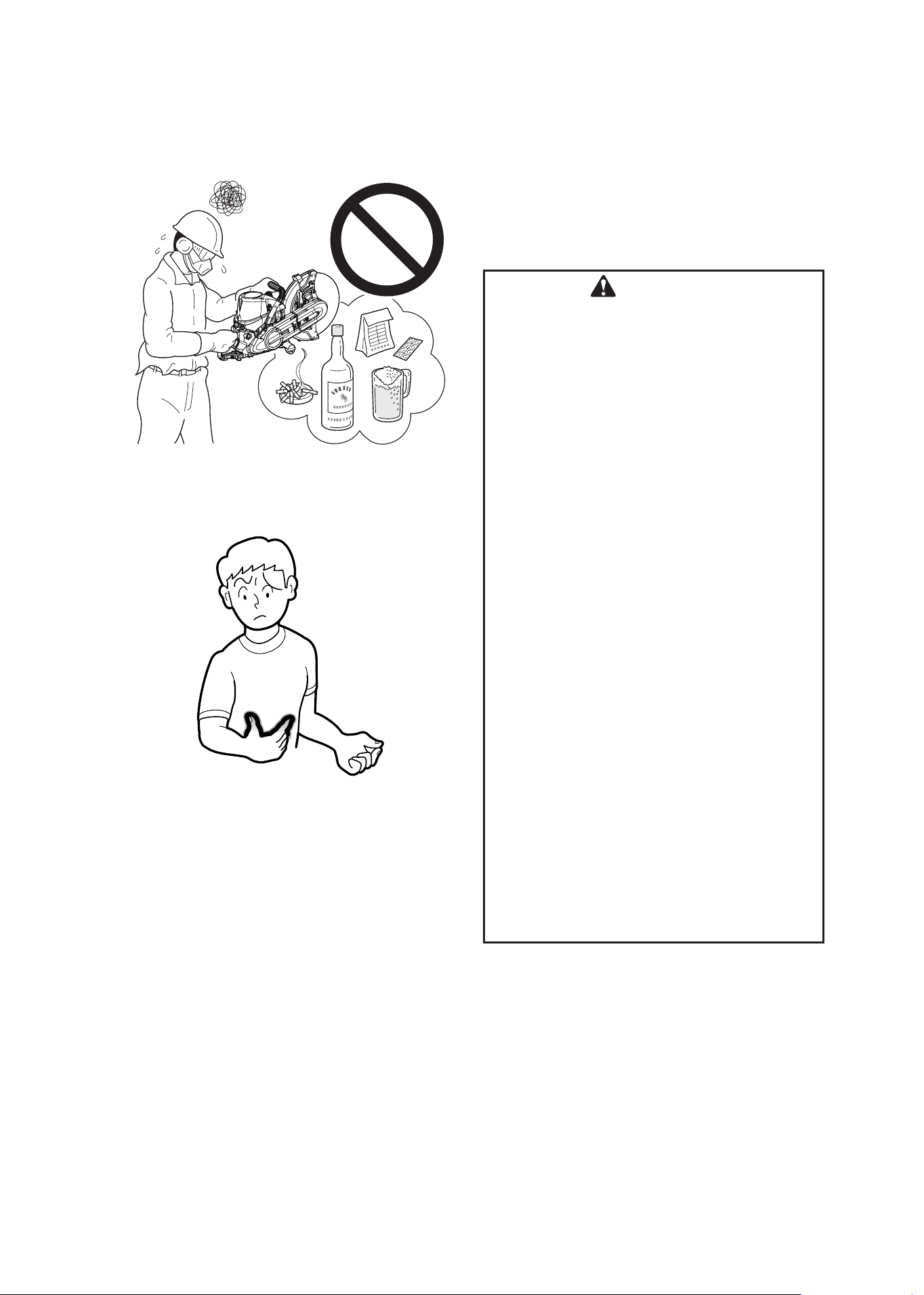
Physical Condition
Your judgment and / or dexterity may be impaired
if you are ill or have taken alcohol or other
substances known to affect the way you would
function normally. Operate only when sound in
mind and body.
WARNING
Precautions Against Vibration and Cold
It is believed that a condition called
Raynaud’s Phenomenon which affects the
fingers of certain individuals is brought
about by exposure to cold and vibration.
Accordingly, your ECHO Engine cut-off saw
has shock mounts designed to reduce the
intensity of vibration received through the
saw handles. Exposure to cold and vibration
may cause tingling and burning, followed by
loss of colour and numbness, in a person’s
fingers. We strongly recommend your
taking the following precautions because the
minimum exposure which might trigger the
ailment is unknown.
Keep your body warm – especially head,
neck, feet and ankles, and hands and
wrists.
Maintain good blood circulation by
performing vigorous arm exercises
during frequent work breaks, and also by
not smoking.
Limit the number of hours of engine cut-
off saw operation. Try to fill a part of each
work day with jobs where operating this
saw or
other hand-held power tools are not
required.
If you experience discomfort, redness and
swelling of the fingers, followed by
whitening and loss of feeling, consult your
physician before exposing yourself further
to cold and vibration.
12
CSG-7410
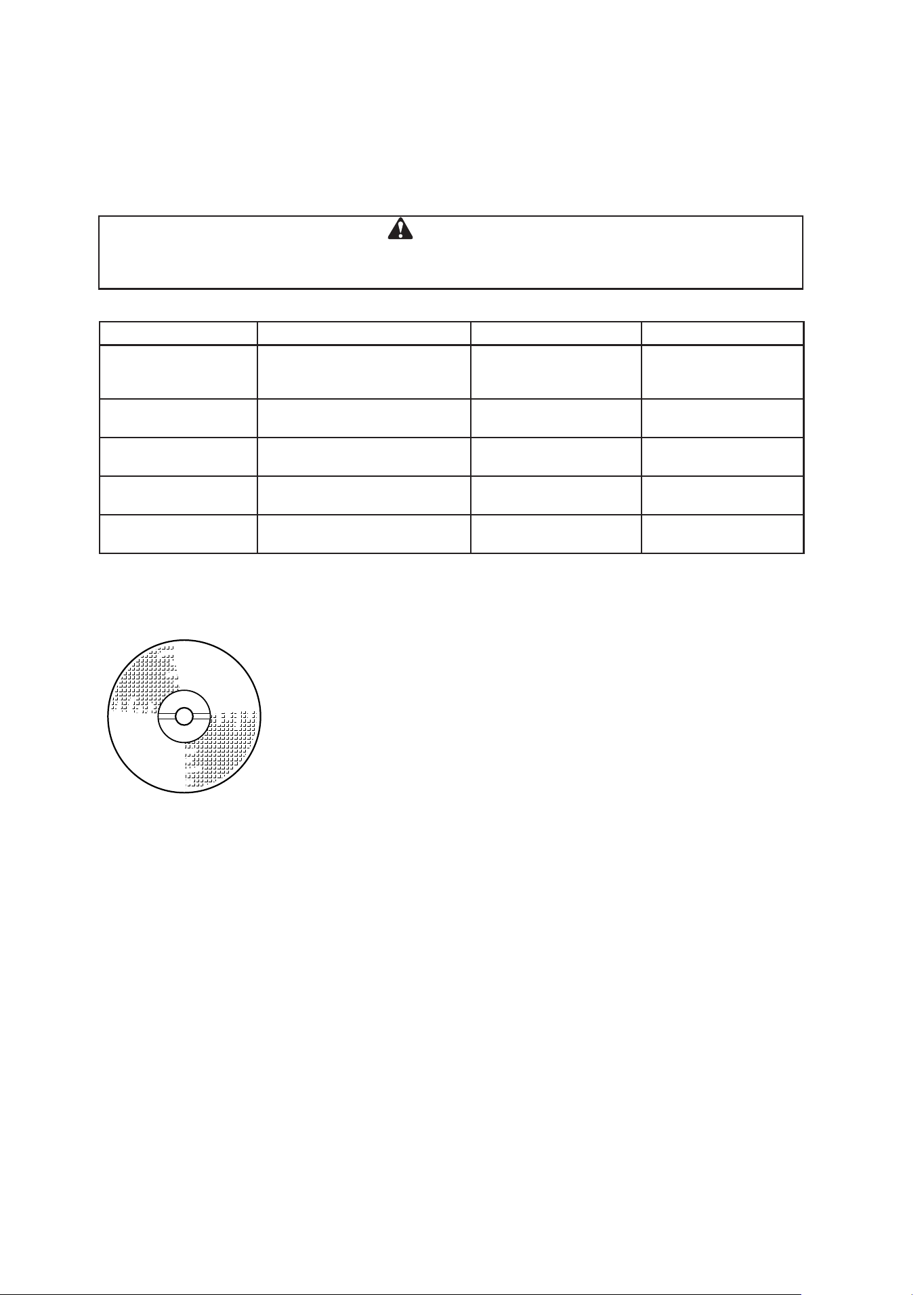
ABRASIVE WHEEL TYPES AND USES
ECHO Reinforced Wheels
ECHO Wheels are labelled for the type of materials they are designed to cut.
The types of wheels identified below, and other types, may be available from ECHO dealer.
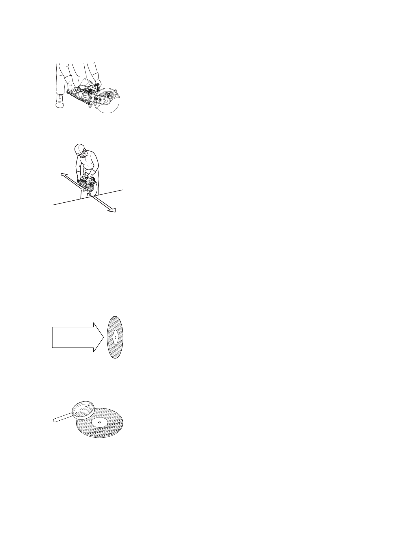
Wheel Speed Rating
This is the minimum acceptable wheel speed rating for this unit. Wheels rated
less than 3820 rpm must not be used on this engine cut-off saw.
Read Label on The
Wheel
Maximum Allowable Wheel Speed
The wheel rotates at the same speed as the spindle (arbour) on which it is
mounted. The wheel must never be allowed to rotate faster than 3820 rpm if
the wheel speed is rated at 3820 rpm.
Labeled Application Primary Use Other Uses Dry or Water Flush
Metal
General purpose mild and
stainless steel: re-bar, pipe
and structural steel
Aluminum and soft
brass. Does not cut
non-metals very well
Dry
Ductile
Ductile or cast Iron and
concrete lined pipe
AII except very hard
metals
Dry. Does not cut well
when wet
Rail Track
Heat treated, wear hardened
and alloyed steel
Not for non-metals Dry
Masonry
All masonry, concrete and
stone products and asphalt
Not for metals
Constant Water Flush
or Dry
Diamond Wheel Rock, block, stone, tile
Not for metal or
reinforced concrete
Dry
WARNING
This saw includes an abrasive wheel and a water system.
Do not use water with an abrasive wheel.
13
CSG-7410
Refer to Chart
Wheel Blotters and Mounting Flanges
Wheel blotters attached to both sides of reinforced
wheels are cushions needed to equalize the
pressure of the mounting flanges from wear if
slippage between the wheel and the flanges
occurs. The blotters are 108 mm (4 1/4
in.)
diameter. Take care that the blotters do not become
gouged or deeply scratched and that there is no
foreign material on them when mounting the wheel.
Emergency Applications
WARNING
Do not grind with a cut-off wheel or put pressure on the sides.
Do not mount wheel if blotters are damaged. Do not destroy
cushioning effect by making mounting bolts too tight.
Never fasten while applying your weight.
Otherwise the thread could be broken.
Proper torque is 25 N•m (250 kgf•cm) - 30 N•m (300 kgf•cm).
Examine wheel carefully before use.
Do not use if wheel is warped, damp, cracked, chipped or cutting
area shows heat discolouration.
Dropping a wheel can easily damage it.
Discard a wheel if you drop it.
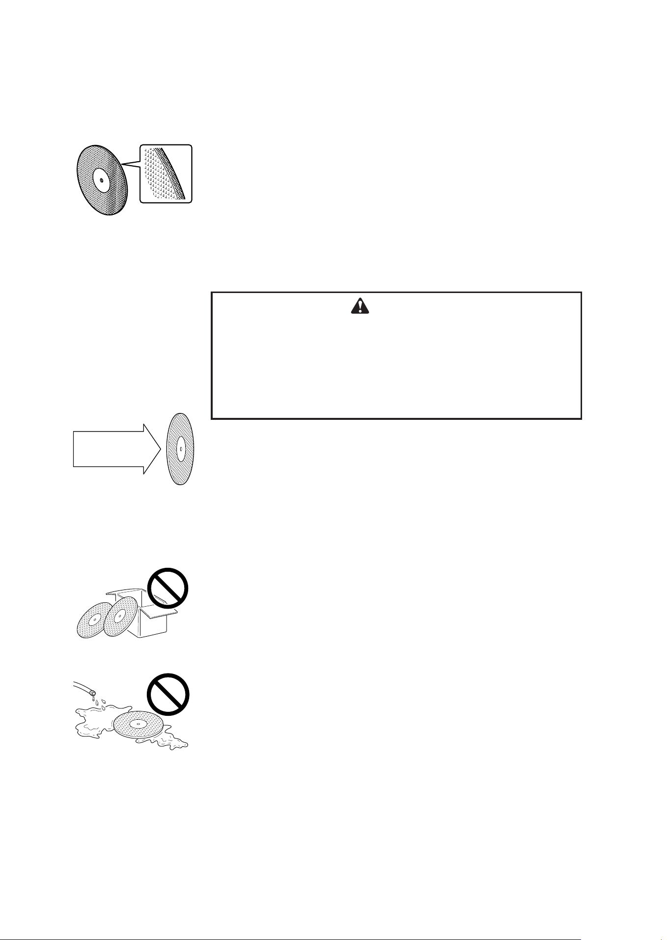
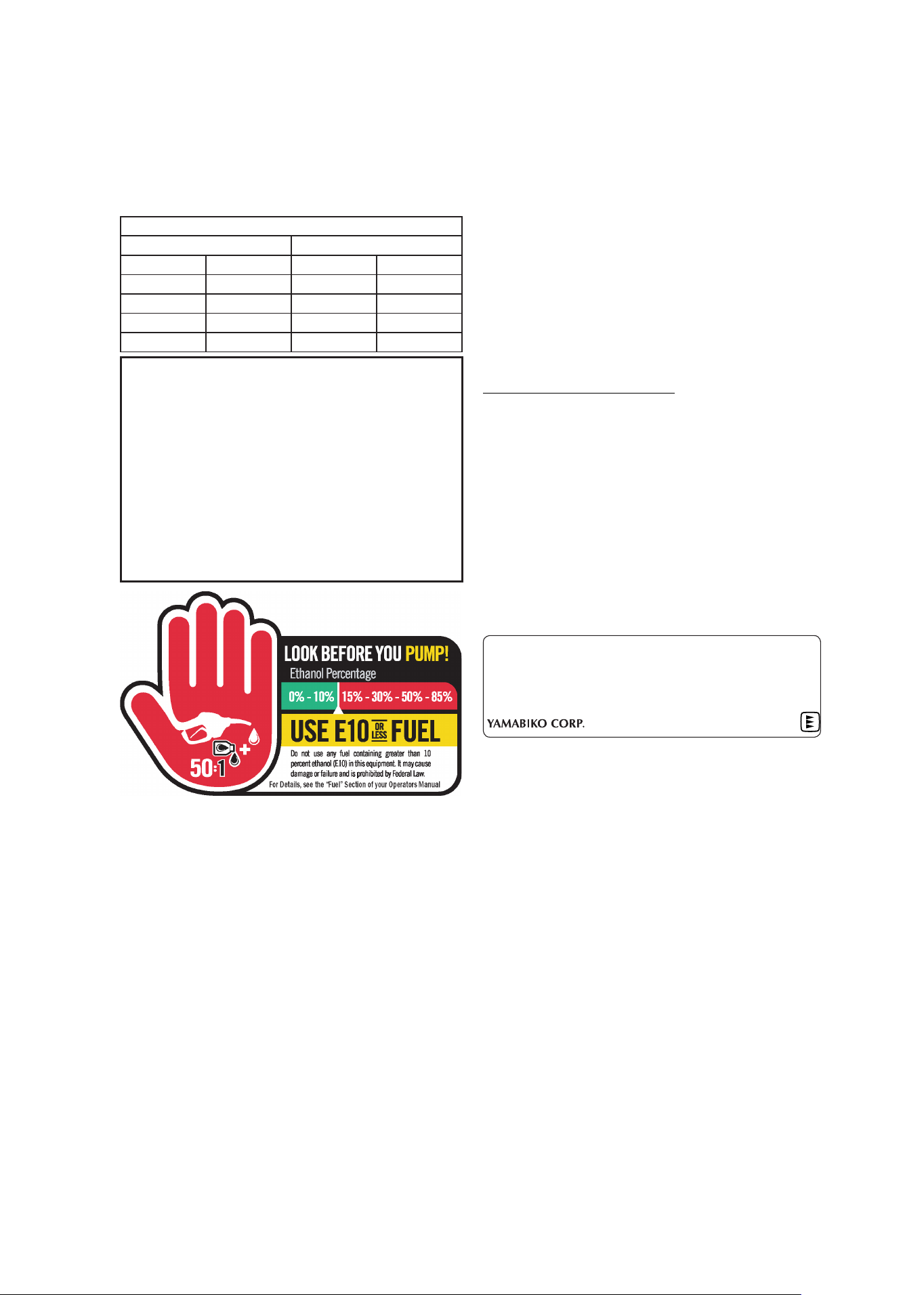
Ring Testing Wheels
Cracks or defects in a wheel may not be visible. To help in verifying that a
wheel is OK to use, a “ring test”. Perform the ring test immediately before
mounting all new or used wheels.
Put your finger through the mounting hole to support the wheel. Use a non-
metallic handle of any small tool or a small piece of wood to lightly tap (do
not hit) the wheel in the locations shown in the illustration. Do not tap wheel
on the edge. Wheels without cracks will make a ringing sound, wheels with
cracks, or concealed cracks, will make a dull “clunk”.
IMPORTANT
If a wheel being “ring tested” is dirty or damp or
is tapped at the vertical centre line, the resulting
sound will be muffled and not reliable.
“Tap” Here
Centre Line
45°
45°
45°
Blotter 108 mm
20 mm
(25.4 mm)
350 mm
45°
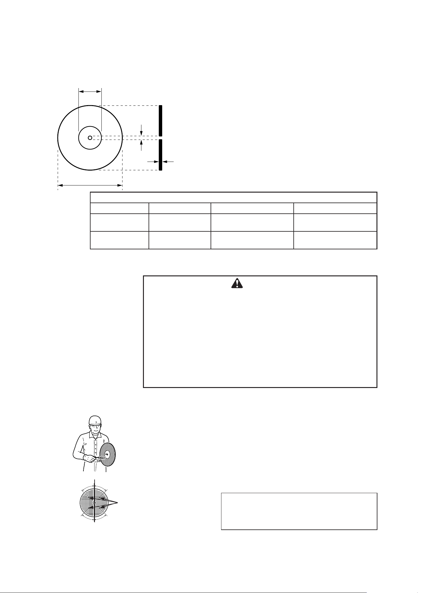
Wheel Dimensions
Wheel Diameter Mounting Hole Diameter Thickness
Abrasive Wheel: 350 mm (13.8 in.)
20 mm
(25.4 mm with Adapter)
Max. 4.7 mm (6/32 in.)
Diamond Wheel: 350 mm (13.8 in.)
20 mm
(25.4 mm with Adapter)
Max. 4.7 mm (6/32 in.)
14
CSG-7410
Facts About Abrasive Wheel
ECHO wheels are made by laying a strong fibre mesh material into a form,
pouring a mixture of resin and the abrasive grit particles over the mesh,
and adding a second layer of mesh over the mixture. Then the resin and
reinforcing mesh are bonded together and cured.
The wheel’s ability to cut certain materials are due to the type abrasive, size
of the grit and it’s spacing. The reinforcement on both sides adds strength
and rigidity.
Always read the label on the wheel. If the wheel does not cut well, it may be
the wrong type for the material. Forcing it to cut may result in shattering of
the wheel and serious injury to the operator.
WARNING
Do not use water with an abrasive wheel.
Do not grind with a cut-off wheel or put pressure on the sides.
Use only ECHO reinforced wheels, or wheels approved for this saw
by ECHO.
Wheels that are too thick or fit the arbour improperly may shatter,
causing serious personal injury. So may wheels of low speed rating
or those that are cracked, warped, out-of-round or edge-damaged.
A wheel can stand a lot of cutting pressure as long as the pressure is straight
on and not from the side of the wheel. This is why you always must make
only straight line cuts.
Saws intended for forcible entry should be equipped with new wheels for
each use. If the used wheels can pass the ring test (page 13) and close
inspection, they may be use in training emergency crews.
Check every wheel for warping, cracks and broken edges before mounting
on the saw.
Warped wheels do not cut properly and may be stressed to the point of
breaking. Always store your wheels laying flat, on a dry surface. When
stacking many wheels, place cardboard or paper spacers between them as a
cushion.
Moisture and heat both can cause wheel damage. Do not let wheels lie in the
sun or expose them to high heat. Keep wheels dry at all times, and store in
an area of low humidity and moderate temperature. Protection from moisture
damage applies during water-flush cutting.
Handling and Storage of Wheels
Put no Side
Pressure on
the Wheel
15
CSG-7410
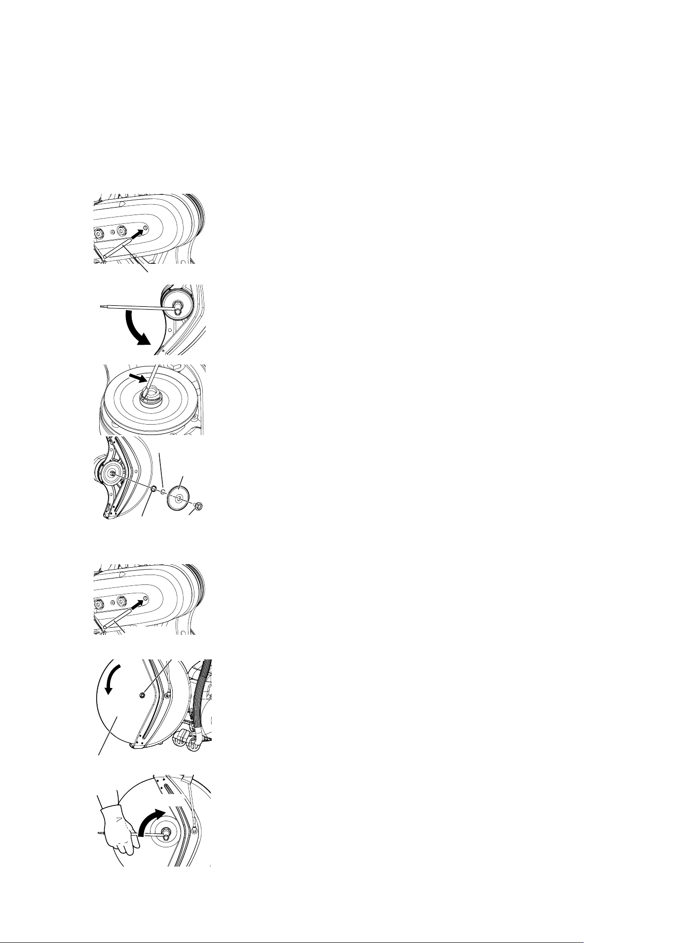
How to Install the Wheel
Replacing the Adapter
Install the adapter that fits the inside diameter of the cutting wheel. When
shipped, an adapter with an outside diameter of 20 mm is mounted. If the
inside diameter of the cutting wheel to be used is 25.4 mm, replace the
adapter as follows.
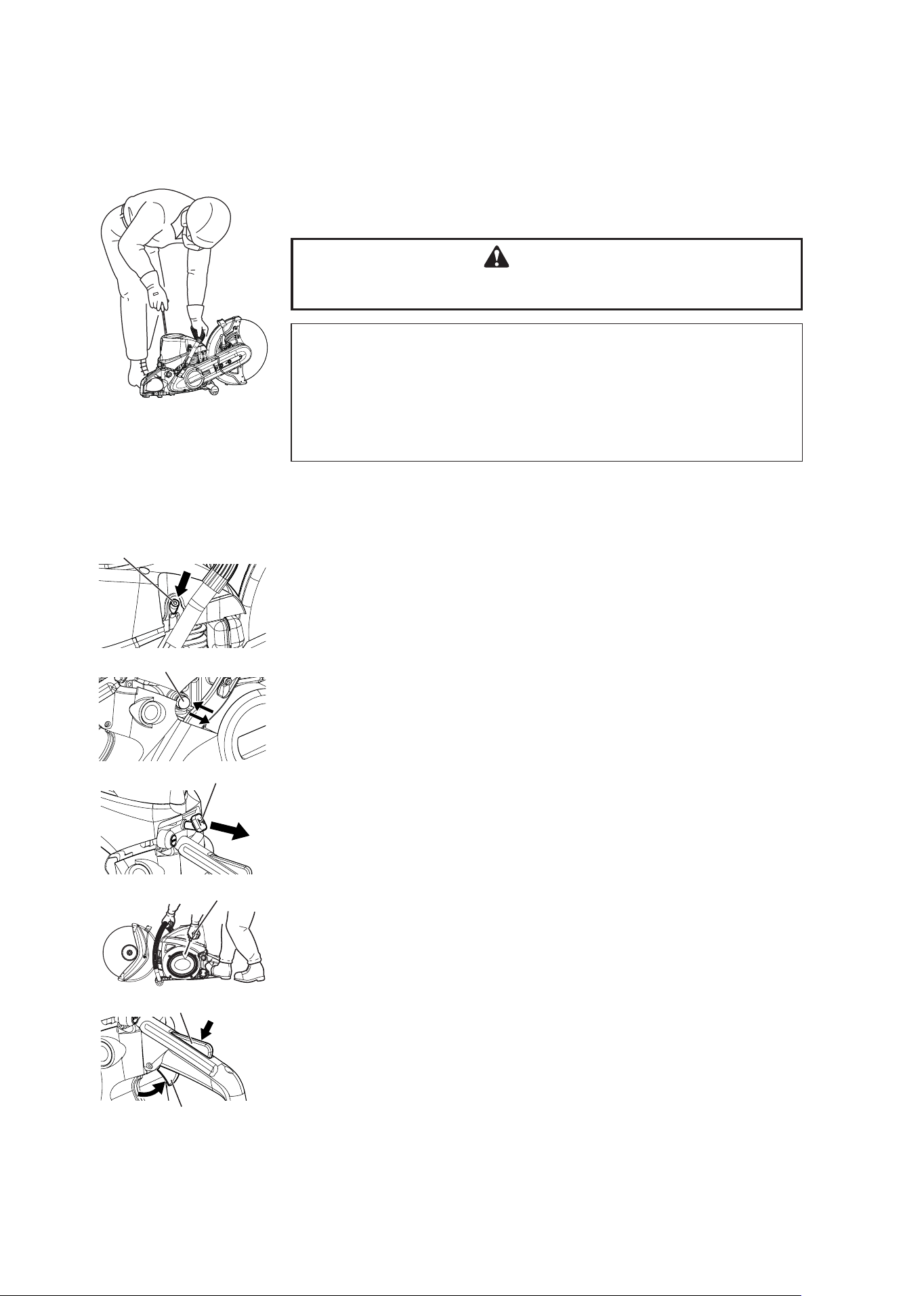
1. Insert the bar tool.
2. Rotate the drive shaft until the hole in the large pulley and the bar tool
aligned.
3. Unscrew wheel mounting bolt with the 19 mm end of the box wrench or
your fingers.
Remove wheel bolt and outer flange, leaving inner flange in place.
4. The adapter is held to the drive shaft with a snap ring. Insert a tool like a
small slotted screwdriver in the gap and remove the snap ring.
5. Replace with an adapter that fits the inside diameter of the cutting wheel
to be used.
6. Press the snap ring in until it reaches the groove in the drive shaft and
secures the adapter. If the snap ring is deformed, replace it with a new one.
Installing a Cutting Wheel
1. Insert the bar tool.
Rotate the drive shaft until the hole in the large pulley and the bar tool
aligned.
2. Unscrew wheel mounting bolt with the 19 mm end of the box wrench or
your fingers.
3. Remove wheel bolt and outer flange, leaving inner flange in place.
4. Confirm the direction of rotation of the cutting wheel and mount it so its
centre hole fits over the adapter mounted on the drive shaft.
5. Align the hole in the cutter flange with the drive shaft and press it on.
6. Finger tighten the wheel bolt and then tighten it fully with a socket wrench.
Tighten it to a torque of 25 to 30 N・m.
7. Remove the bar tool and rotate the cutting wheel by hand; make sure it is
straight and wobble-free.
Bar Tool
Bolt
Cutting Wheel
Tighten
PREPARATION FOR USE
Snap ring
Adapter
Flange
Bar Tool
Adapter
16
CSG-7410
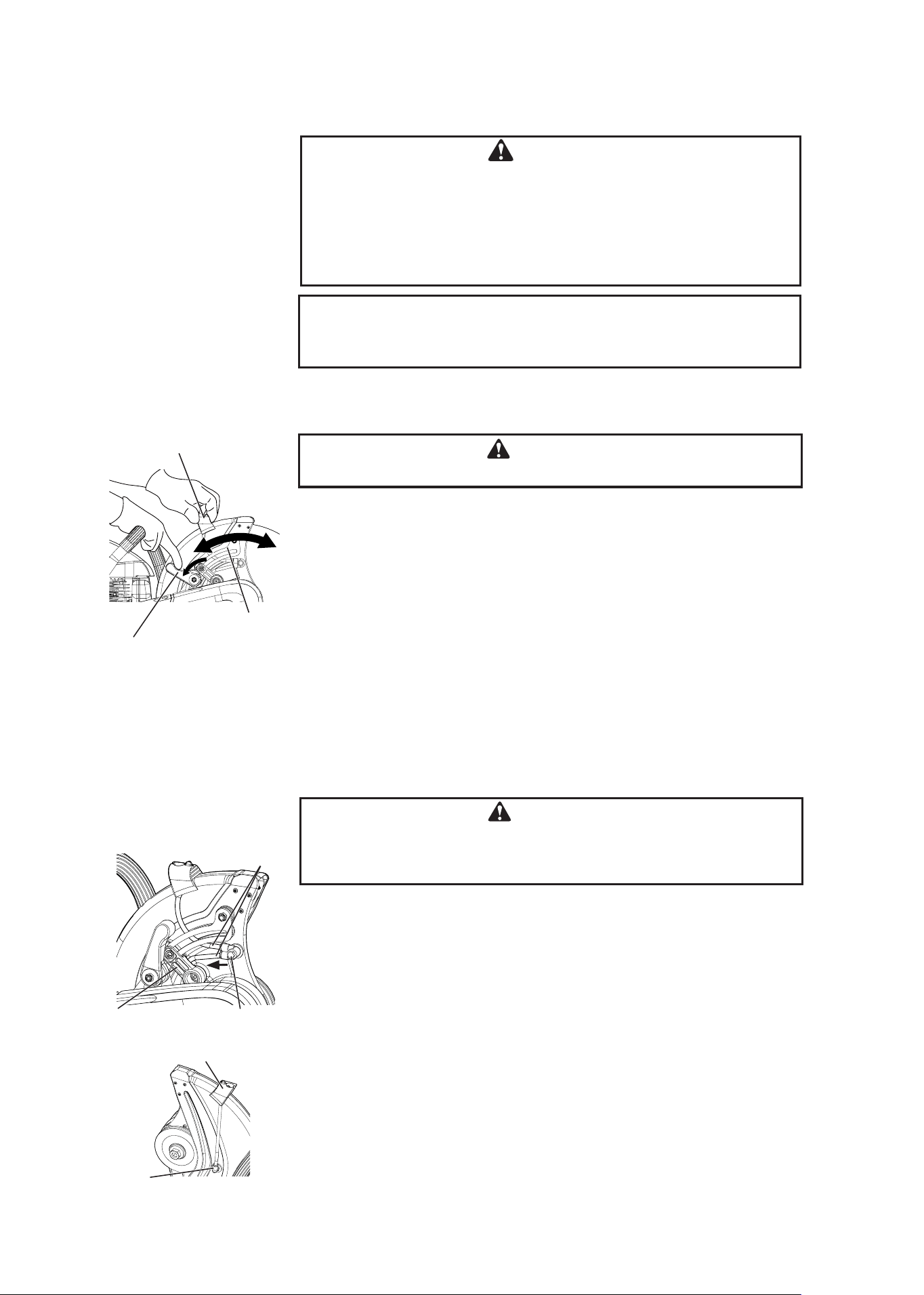
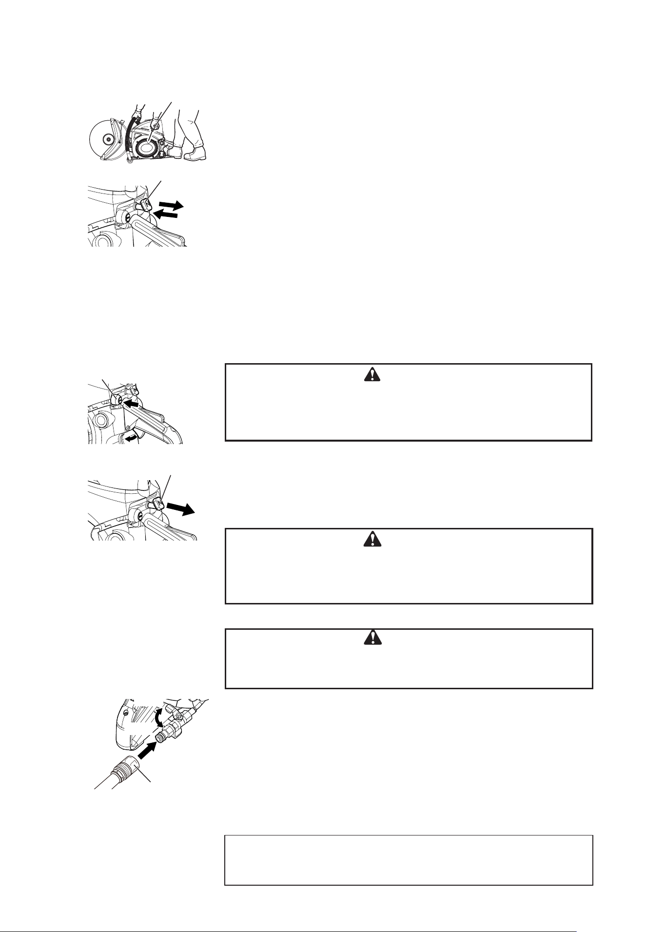
Adjusting the Wheel Guard Angle
1. The wheel guard can be adjusted to prevent debris from flying off and hitting the
operator.
2. Turn the wheel guard locking knob counterclockwise, grasp the wheel guard
knob and move the wheel guard to the desired position, then slowly release it and
secure the wheel guard with the locking knob.
* Never operate the machine without the guard stopper in place.
WARNING
Never operate the machine without the wheel guard in place.
Wheel guard
Locking knob
Wheel guard
WARNING
Before tightening, check that flanges are properly seated and not
cocked on the mount or bolt threads. Do not make bolt so tight
as to destroy the cushion supplied by the wheel blotters. Do not
use pneumatic, electric-powered tools or one’s body weight for
tightening. Otherwise the thread could be broken. Do not tighten
more than 30 N•m (300 kgf•cm).
NOTE
Arm may be removed and remounted with wheel on the outboard side of
the arm as required for certain procedures.
Reverse Mounting the Cutter Arm
When shipped the cutting wheel is mounted so it is near the center of gravity of
the machine. The cutting wheel can be moved to a position outside the machine
by reverse mounting the cutter arm.
WARNING
Reverse mounting the cutter arm compromises the balance of
the machine and makes it difficult to operate. Do not use it in the
reversed state except when necessary.
1. Remove the cutting wheel.
2. Remove the 2 screws and remove the guard stopper.
3. Remove both of the pipes connected to the pipe connector. Remove the pipe
connector after removing the nut mounted on the wheel guard.
4. Mount the pipe connector in the lower hole in the wheel guard.
5. Loosen the nut that holds the nozzle in place.
6. Remove the wheel guard knob mounted on the wheel cover.
Guard Stopper
Pipe
connector
Pipe
Nozzle
Wheel guard knob
Wheel guard knob
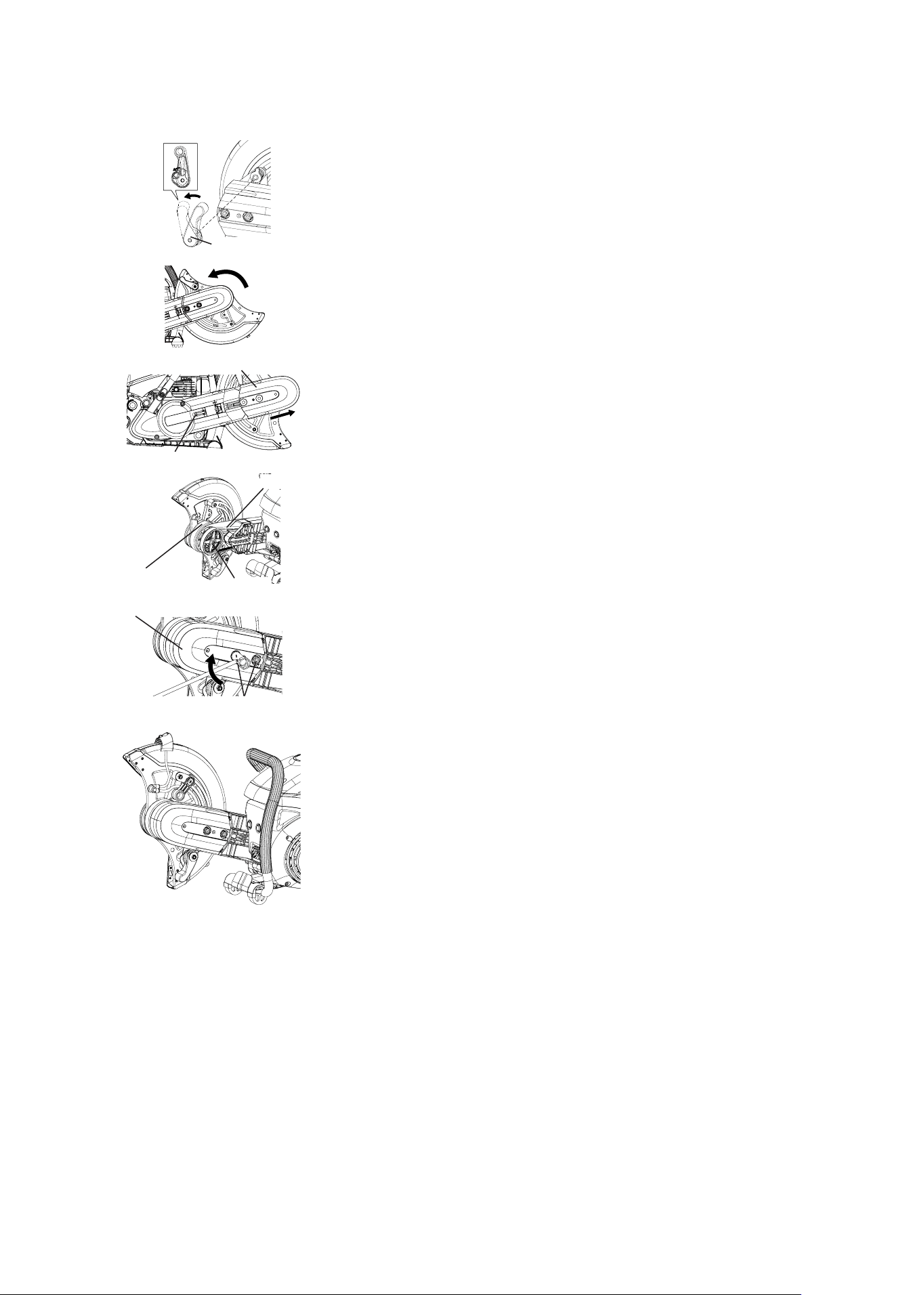
17
CSG-7410
Locking Knob
Pulley cover
Tension screw
Belt
Pulley
Cutter arm
Bolt
Pulley cover
7. Loosen the nut of the locking knob and reinstall it after changing the angle of
the knob.
8. Change the angle of the wheel guard.
9. Loosen the tension screw until its tip cannot be seen, then remove the 2 pulley
cover bolts.
10. Remove the pulley cover.
11. Remove the cutter arm from the crankcase. Remove the belt at the same time.
12. Reverse the cutter arm and mount it in the long hole in the crankcase.
13. Put the belt on the pulley.
14. Put the pulley cover into the cutter arm. Make sure the pulley cover is not mis-
aligned when putting it into the arm.
15. Finger tighten the 2 pulley cover bolts, then back them off about 1 turn. Adjust
the tightness of the belt.
16. Tighten the 2 pulley cover bolts. Note: Tighten it to a torque of 23 to 27N・m (230
to 270 kgf・cm).
17. Change the nozzle angle and then tighten the nut.
18. Insert the 2 pipes into the pipe connector.
19. Mount the knob on the top of the wheel guard.
20. Install the guard stopper on the guard (above the cutting arm).
18
CSG-7410
FUEL AND LUBRICANT
WARNING
Diesel fuels and alternative fuels, such as
E-15 (15% ethanol), E -85 (85% ethanol) or
any fuels not meeting ECHO requirements
are NOT approved for use in ECHO 2-stroke
gasoline engines. Use of diesel or alternative
fuels may cause performance problems, loss
of power, overheating, fuel vapor lock, and
unintended machine operation, including, but
not limited to, improper clutch engagement.
Diesel or alternative fuels may also cause
premature deterioration of fuel lines, gaskets,
carburetors and other engine components.
FUEL
Fuel Requirements
Gasoline - Use 89 Octane [R+M/2] (mid grade or
higher) gasoline known to be good quality. Gasoline
may contain up to 10% Ethanol (grain alcohol) or 15%
MTBE (methyl tertiary-butyl ether). Gasoline contain-
ing methanol (wood alcohol) is NOT approved. Use of
ECHO brand fuel is recommended to extend engine
life in all air-cooled 2-stroke and 2/4-stroke hybrid
engines.
Two Stroke Oil - A two-stroke engine oil meeting ISO-L-
EGD (ISO/CD 13738) and J.A.S.O. FD Standards must
be used. ECHO brand 2-stroke oils meet these stan-
dards. Engine problems due to inadequate lubrication
caused by failure to use an ISO-L-EGD (ISO/CD 13738)
and J.A.S.O. M345-FD certified oil, such as ECHO brand
2-stroke oils, will void the two-stroke engine warranty.
WARNING
2-Stroke engine oil contains petroleum
distillates and other additives that may be
harmful if swallowed. Heated oil can release
vapors that can cause flash fire, or ignite
with explosive force. Read and follow the oil
manufacturer’s instructions, and observe all
safety warnings and precautions for handling
flammable liquids. For more detailed safety and
first aid information, visit www.echo-usa.com
for a copy of the Material Safety Data Sheet.
• KEEP OUT OF REACH OF CHILDREN.
• If swallowed, do not induce vomiting. CALL
PHYSICIAN OR A POISON CONTROL
CENTER IMMEDIATELY.
• WEAR SAFETY GLASSES when mixing or
handling.
• AVOID repeated or prolonged skin contact
• AVOID inhaling oil mists or vapors.
NOTICE
ECHO brand 2-stroke oils may be mixed at
50:1 ratio for application in all ECHO engines
sold in the past regardless of ratio specified
in those manuals.
Handling Fuel
DANGER
Fuel is VERY flammable. Use extreme care
when mixing, storing or handling, or serious
personal injury may result.
Use an approved fuel container. Mark fuel
containers as containing 2-stroke mixture
fuel.
• DO NOT smoke near fuel.
• DO NOT allow flames or sparks near fuel.
• Fuel tanks/cans may be under pressure.
Always loosen fuel caps slowly allowing
pressure to equalize.
• NEVER refuel a unit when the engine is
HOT or RUNNING!
• DO NOT fill fuel tanks indoors. ALWAYS
fill fuel tanks outdoors over bare ground.
• DO NOT overfill fuel tank. Wipe up spills
immediately.
• Securely tighten fuel tank cap and close
fuel container after refueling.
• Inspect for fuel leakage. If fuel leakage is
found, do not start or operate unit until
leakage is repaired.
• Move at least 3 m (10 ft.) from refueling
location before starting the engine.
DANGER
Gasoline vapor is heavier than air, and can
travel along the ground to nearby sources of
ignition such as electrical motors, pilot lights,
and hot or running engines. Vapors ignited
by an ignition source can flash back to the
fuel container, resulting in an explosion,
fire, serious or fatal injuries, and extensive
property damage.
19
CSG-7410
Mixing Instructions
1. Fill an approved fuel container with half of the re-
quired amount of gasoline.
2. Add the proper amount of 2-stroke oil to gasoline.
3. Close container and shake to mix oil with gasoline.
4. Add remaining gasoline, close fuel container, and
remix.
Fuel to Oil Mix – 50:1 Ratio
US Metric
Gas Oil Gas Oil
gal. fl.oz. L cc
1 2.6 5 100
2 5.2 10 200
5 13 25 500
NOTICE
Stored fuel ages. Do not mix more fuel than
you expect to use in 30 days, 90 days when a
fuel stabilizer is added.
Stored two-stroke fuel may separate.
ALWAYS shake fuel container thoroughly
before each use.
Used oil and gasoline, and soiled towels are
hazardous waste materials. Disposal laws
vary by locality.
EMISSION DATA
EMISSION CONTROL
(EXHAUST and EVAPORATIVE)
EPA 2010 and Later and/or C.A.R.B. TIER III
The emission control system for the engine is EM
(engine modification) and, if the second to last
character of the Engine Family on the Emission
Control Information label (sample below) is “C”, “K”,
or “T”, the emission control system is EM and TWC
(3-way catalyst). The fuel tank/fuel line emission
control system is EVAP (evaporative emissions).
Evaporative emissions for California models may
only be applicable to fuel tanks.
An Emission Control Label is located on the
engine ( example only, information on label varies
by engine family).
PRODUCT EMISSION DURABILITY
(EMISSION COMPLIANCE PERIOD)
The 300 hours emission compliance period is
the time span selected by the manufacturer
certifying the engine emissions output meets
applicable emissions regulations, provided that
approved maintenance procedures are followed
as listed in the Maintenance Section of this
manual.
EMISSION CONTROL INFORMATION
ENGINE FAMILY: #EHXS.0735RA DISPLACEMENT: 73.5 cc
EMISSION COMPLIANCE PERIOD: 300 Hours
THIS ENGINE MEETS U.S. EPA EXH/EVP EMISSION
REGULATIONS FOR MODEL YEAR **** REFER TO OWNER’S MANU-
AL FOR MAINTENANCE SPECIFICATIONS AND ADJUSTMENTS.
***XXXX
20
CSG-7410
WHEN THE ENGINE IS COLD
1. Fill the fuel tank with fuel mixture. It is not permitted to fill fuel above the
shoulder level of fuel tank.
2. Press the decompression device.
3. Push primer pump until fuel is visible in primer pump.
4. Pull out choke all the way (engages the fast idle throttle latch setting).
5. Securely hold the engine cut-off saw. Pull starter grip briskly, but only 1/2
to 2/3 its full length. Pulling rope to the end may damage the starter.
6. Push in the choke the first time engine fires, and crank until engine starts
and runs. In cold weather you should keep the choke out just a little until
the engine gets very warm. But, do not operate with the choke out.
7. Squeeze and release trigger when engine runs to release the fast idle
throttle latch setting. You now have trigger control of the throttle speed.
Set saw down on level ground with wheel in the clear. Grasp front handle
with left hand, and hold down rear handle with toe of your boot. Never “drop-
start” the saw.
WARNING
Wheel will rotate when engine is started at fast idle throttle latch set-
ting. Keep cutting wheel in the clear.
IMPORTANT
Check unit for loose nuts, bolts and screws before starting.
Make sure the wheel guard is securely in place.
Always clear work area of debris before starting operation.
Always hold the unit firmly.
When pulling starting rope, use short pulls, 1/2 to 2/3 of rope length.
Do not allow the starter grip to snap back against the housing.
OPERATION
Safe Starting Techniques
Decompression device
Primer pump
Choke
Starter grip
Throttle trigger lockout
Throttle trigger
21
CSG-7410
Stopping Engine
Release throttle trigger and allow engine to idle.
Push the momentary stop switch.
The engine stops with just one press of the stop switch. It is not necessary to hold the
switch until it stops.
If engine does not stop, pull choke control knob out fully to stop engine. The choked
engine will slow to a stop. Be sure to keep the wheel in the clear until all movement stops.
RUNNING
1. Once the engine starts, allow it to warm up for 2 to 3 minutes at idling (i.e.
low speed).
2. Warming the engine helps to lubricate its internal workings more smoothly.
Allow the engine to warm up fully, especially when it is cold.
WHEN THE ENGINE IS WARM
1. Fill the fuel tank with fuel mixture. It is not permitted to fill fuel above the
shoulder level of fuel tank.
2. Press the decompression device.
3. Securely hold the engine cut-off saw. Pull starter grip briskly, but only 1/2
to 2/3 its full length. Pulling rope to the end may damage the starter.
* If the engine is hard to start, pull the choke to engage the fast idle throttle
latch setting, then return the choke to its normal position (this opens the
throttle slightly).
If it still fails to start, revert to the WHEN ENGINE IS COLD starting
procedure.
WARNING
With trigger latched, wheel will rotate as soon as engine starts. Keep
wheel in the clear.
Wheel will rotate for some time after the trigger is released. Keep
wheel in the clear until all movement stops.
Starter grip
Choke
Momentary stop switch
Choke
WARNING
Momentary stop switch automatically returns to run position. Engine
can start unintentionally when starter handle is pulled. Always
remove spark plug lead from spark plug before pulling starter
handle, otherwise severe personal injury may result.
Dust Suppression
WARNING
Do not use with wheels that are not designed to be used with wa-
ter-flush cutting.
Doing so may damage the wheel while it is being used.
1. Use water-flush cutting when doing work that generates a lot of dust, such
as cutting concrete.
2. Attach a water hose with a coupler on it to the joint of the engine cut-off
saw.
3. Make sure the liquid cock is in the closed position before turning the water
faucet on.
4. Adjust the water flow with the liquid cock.
5. After cutting, turn off the water and let the wheel spin itself dry.
IMPORTANT
Make sure there are no water leaks before use.
Use as little water as possible to sufficiently suppress generation of dust.
Open
Close
Coupler
22
CSG-7410
CUTTING INSTRUCTION
1. Squeeze and release trigger to unlatch it and take control of the throttle.
2. Let engine warm to operating temperature before doing any cutting.
3. Take cutting stance on left side of saw. Never get any part of your body
behind the saw. Hold the saw firmly with both hands. Throttle up to cutting
speed and make gentle wheel contact with the work.
Sequence after Starting Engine
Cutting Asphalt, Tar and Reinforced Materials
Old, cold and hardened asphalt paving can be cut with a masonry wheel with
good results and little trouble with tarring of the wheel. Fresh asphalt and
tarred surfaces can gum up the wheel and slow its cutting action. Some tar
or resin-impregnated materials also may present problems of this sort.
Masonry containing metal reinforcement is best cut with a masonry wheel
which can cut through the reinforcing steel better than a wheel designed for
metal can cut the masonry. Expect faster than normal wheel wear.
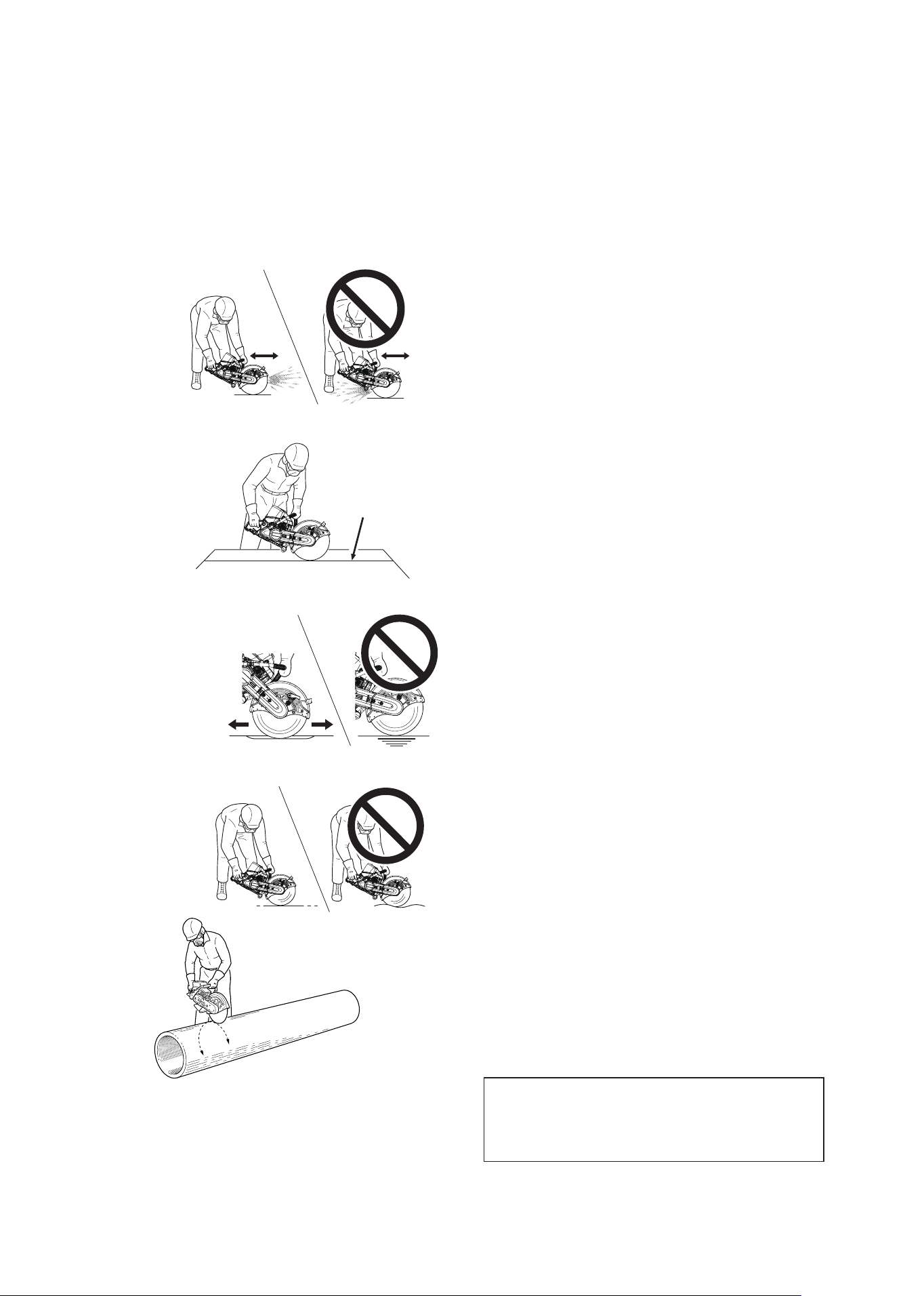
DANGER
Do not raise saw above chest height, because the saw is hard to
control when held up high, and dust or sparks will fall on you.
Wear hearing protection. Without it you risk hearing loss,
especially where bounce-back of sound waves off nearby surfaces
increases the noise.
Do not take awkward or risky operating positions. Find solid
footing for both feet, and always hold the saw firmly with both
hands. Never make one-handed cuts.
DANGER
Kickback may force the cutting-off wheel up and back toward the
operator with a lightning-fast reaction. Kickback can occur whenever
the upper-half of the cutting-off wheel touches an object while op-
erating the machine. This may cause the cutting wheel to touch the
operator, resulting in serious injury
Rotational kickback
Cutting with the upper part of the cutting wheel generates kickback
from the material being cut; this causes the tip of the cutting wheel
to kick back from the rotation and is extremely dangerous. Always
cut with the bottom of the cutting wheel.
Linear kickback
When cutting with the bottom of the cutting wheel, the machine may
generate a force that pulls the machine forward. Always hold the
handle firmly while working.
Kickback safety precautions
Rotational kickback
Linear kickback
23
CSG-7410
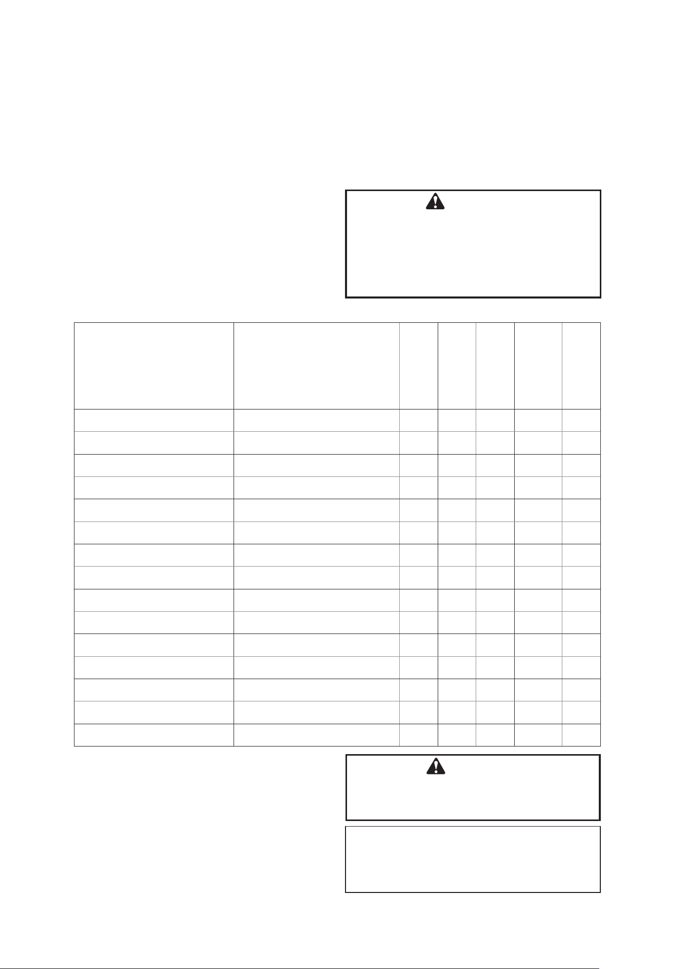
Cutting Technique
The main objectives are to avoid overheating the
wheel, and to prevent it from being pinched or
trapped or stressed in any way.
Adjust position of wheel guard to direct the
discharge away from you.
Prepare to make straight cuts only. Use a snap-
line to mark long cuts, and follow the marked line
carefully.
Take a balanced, comfortable stance on the left
side of the saw. Hold saw firmly with both hands.
Always throttle up to cutting speed before letting
the wheel make contact. The saw may be jerked
forward, causing loss of control, if wheel is in
contact during throttling up. Carefully let cutting
edge of wheel make light contact with the work.
Do not push or bounce the wheel onto the work.
Hold saw steady. Do not let it tilt or wobble.
Do not let the wheel stop in one place, but keep
it moving - in one direction, or back and forth,
along the line of cut. Cutting in one spot causes
heat build-up which can damage or glaze the
wheel. Too much cutting pressure also causes
overheating.
Cut as shallow and straight a groove as you can.
If you cut a curve, the wheel will start to bind as
the cut deepens.
Go over and over the groove you have started
until the cut is completed.
On cuts of long duration, remove saw from cut
often to let the wheel cool.
Never put any side pressure on a engine cut-off
saw wheel, grind on the side of it or use it to flick
away debris.
When cutting large diameter pipe, cut 360
degrees around and try not to cut through. If a
large segment of the wheel breaks through, the
wheel may catch and kick out at lightning-fast
speed.
Before cutting materials which are not supported
along their entire length, provide support to
prevent binding. Also be aware that the top
section will settle on the wheel if a column is cut
in two.
Be careful not to cut your own legs in the
downward cutting. Be particularly careful at the
end of cutting.
NOTE
Always cut at full throttle. Cutting at less than full
throttle may harm the clutch as it will overheat
during slippage.
Keep Wheel
Moving
Cut in a
Straight Line
Saw will Bind
in Crocked Cut
Roll Pipe to Cut 360° Around
Try not to Let Wheel Break
Through in One Place
Follow Snap Line
24
CSG-7410
MAINTENANCE AND CARE
IMPORTANT
Time intervals shown are maximum.
Actual use and your experience will determine
the frequency of required maintenance.
Your ECHO engine cut-off saw is designed to
provide many hours of trouble free service. Regular
scheduled maintenance will help your engine cut-
off saw achieve that goal. If you are unsure or are
not equipped with the necessary tools, you may
want to take your unit to an ECHO Service Dealer
for maintenance. To help you decide whether you
want to DO-IT-YOURSELF or have the ECHO Deal-
er do it, each maintenance task has been graded.
If the task is not listed ask your ECHO dealer for
repairs.
SKILL LEVELS
Level 1 = Easy to do. Most required tools come
with unit.
Level 2 = Moderate difficulty. Some specialized
tools may be required.
WARNING
Momentary stop switch automatically
returns to run position. Engine can start
unintentionally. Always remove spark plug
lead from spark plug before assembling
or performing maintenance procedures or
serious personal injury can result.
MAINTENANCE INTERVALS
Maintenance Procedure Letter Codes:
I = Inspect
C = Clean
R = Replace
Maintenance Procedure Notes:
* = All recommendations to replace are based
on the finding of damage or wear during
inspection.
Component / system Maintenance procedure
Required Skill
level
Daily or Before
use
Every refuel
Every 50 hours
or Yeary
Every 100
hours
Air Filter Inspect / Replace 1 I R *
Fuel System Inspect / Clean / Replace 1 I * I *
Fuel Filter Inspect / Replace 1 I / R *
Fuel Cap Gasket Inspect / Replace 1 I * R *
Wheel Inspect / Replace 1 I I
Wheel guard Inspect / Clean 1 I / C
Flange Inspect / Clean / Replace 1 I / C *
Belt Inspect / Tensioning / Replace 1 I I / R *
Clutch Inspect / Replace 2 I *
Spark Plug Inspect / Clean / Replace 1
I / C /
R *
Cooling System Inspect / Clean 1 I / C
Muffler Spark Arrestor Inspect / Clean / Replace 2 I
I / C /
R *
Cylinder Exhaust Port Inspect / Clean / Decarbon 2 I / C
Recoil Starter Rope Inspect / Clean 2 I / C *
Screws / Nuts / Bolts Inspect / Tighten / Replace 1 I *
WARNING
When replacing parts, always use ECHO
genuine parts. Using non genuine parts may
result in serious injury.
25
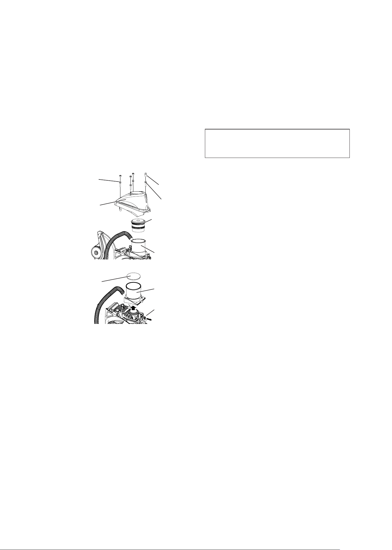
CSG-7410
Main air filter
Filter case
Sub air filter
Choke knob
Air Filter
Air Cleaner
Cover
The air filters of this product are designed to
be maintenance-free for a long period of time.
However, in the following cases the main and sub
air filters should be replaced.
・If engine output drops markedly
・After 1 year or 50 hours of operation
IMPORTANT
Do not attempt to clean the main or sub air filters
with compressed air.
Bolts (A)
Grommets
Air Filter Replacement Procedure
1. Remove the 4 grommets on the air cleaner cover.
2. Remove the 4 bolts securing the air cleaner
cover and then remove the cover.
3. Remove the main and sub air filters. The sub air
filter can be removed by pulling out the choke
and lifting up the filter case and then pressing on
the filter from the under side.
4. Put the filter case back in position.
5. Install new sub and main air filters. Replace both
filters at the same time.
6. Install the air cleaner cover and tighten its 4
bolts. Tighten the 3 bolts (A) and then the bolt (B).
7. Make sure the grommets are facing the right way
when installing them on the air cleaner cover.
Filter case
Bolt (B)
26
CSG-7410
(Check Periodically)
1. Do not allow dust to enter fuel tank.
2. Clogged filter will cause difficulty in starting
engine or abnormalities in engine performance.
3. Pull the fuel filter out through fuel inlet port with
a piece of steel wire or the like.
4. When the filter is dirty, replace it. Do not attempt
to clean the filter.
5. When the inside of the fuel tank is dirty, rinsing
the tank out with petrol can clean it.
WARNING
Check condition of fuel cap and gasket. Be
sure the cap fits tightly and there is no fuel
leak.
Fuel Filter
Fuel Tank Cap
Replace Fuel Filter
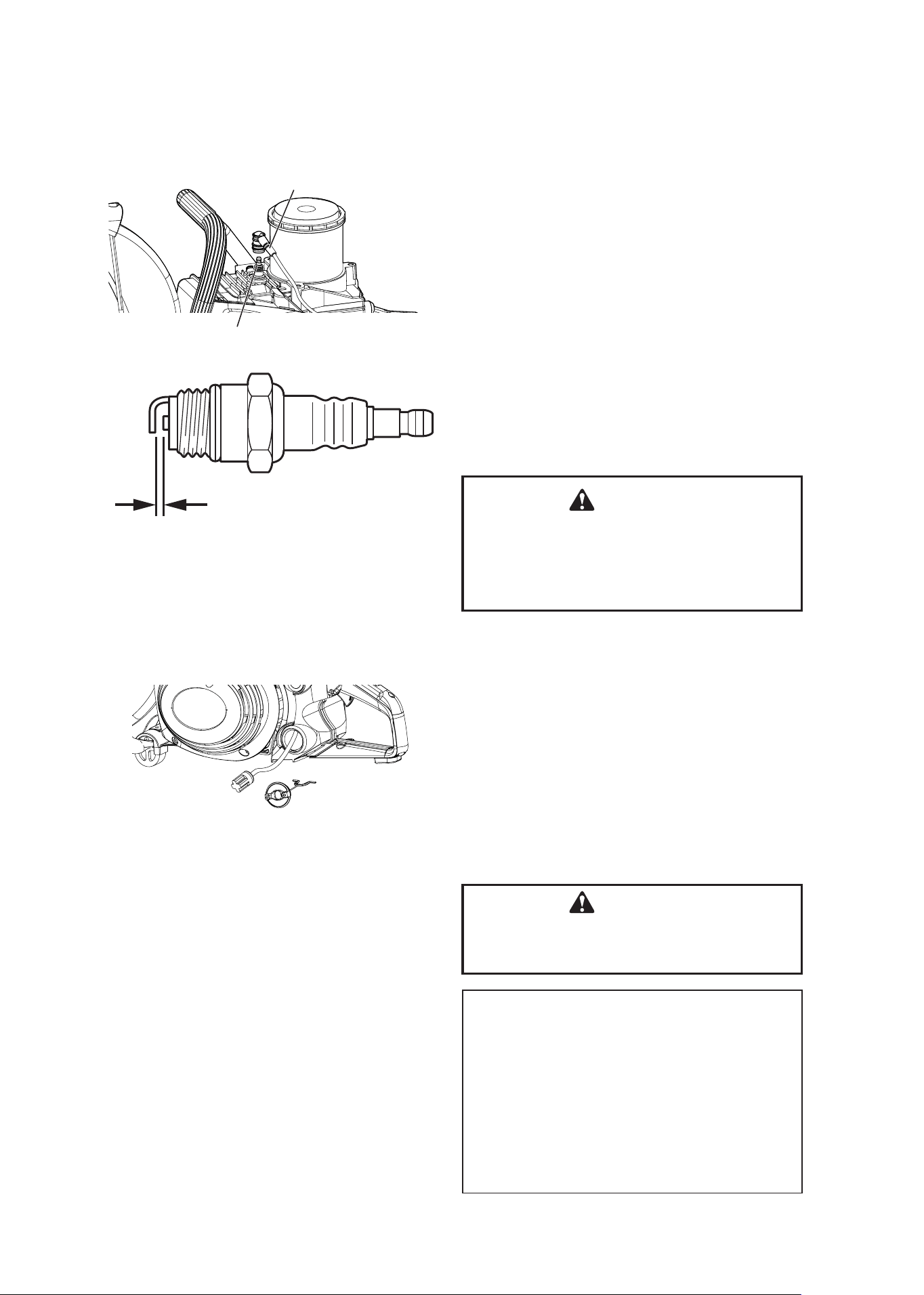
Spark Plug
1. Remove air cleaner cover.
2. Remove spark plug lead.
3. Remove spark plug.
4. The proper spark plug for this engine is NGK
BPMR7A. The firing gap between the electrodes
should be adjusted to 0.65 mm (0.026 in) before
use.
5. Install the spark plug. Proper tightness with a
cold engine is 17 to 19 N•m (170 to 190 kgf•cm).
6. Many failed plugs can be restored by filing or
scraping the electrodes down to bare metal,
cleaning all deposits off the porcelain insulation
around the centre electrode, then setting the
gap.
WARNING
Fuel vapours are extremely flammable and
may cause fire and/or explosion. Never test
for ignition spark by grounding spark plug
near cylinder plug hole, otherwise serious
personal injury may result.
0.65 mm (0.026 in)
Spark plug lead
Spark plug
NOTE
Federal EPA regulations require all model year
2012 and later gasoline powered engines produced
for sale in the United States to be equipped with a
special low permeation fuel supply hose between
the carburetor and fuel tank. When servicing model
year 2012 and later equipment, only fuel supply
hoses certified by EPA can be used to replace
the original equipment supply hose. Fines up to
$37,500 may be enforced for using an un-certified
replacement part.
27
CSG-7410
Carburetor Adjustment
Idle adjusting screw
High Altitude Operation
This engine has been factory adjusted to maintain
satisfactory starting, emission, and durability
performance up to 1100 feet above sea level (ASL)
(96.0 kPa).
To maintain proper engine operation and emission
compliance above 1100 feet ASL the carburetor
may need to be adjusted by an authorized ECHO
service dealer.
IMPORTANT
If the engine is adjusted for operation above
1100 feet ASL, the carburetor must be
readjusted when operating the engine below
1100 feet ASL, otherwise severe engine damage
may result.
Low speed needle (L)
High speed needle (H)
Every unit is run at the factory and the carburetor is
set in compliance with Emission Regulations.
In addition, the carburetor is equipped with “H” (High
Speed) and “L” (Low Speed) needle adjustment
limiters that prevent settings outside acceptable
limits.
1. Before adjusting carburetor clean or replace air
filter and muffler “Spark Arrestor Screen”.
2. Install the wheel.
3. Start engine and run several minutes to bring to
operating temperature.
Flash choke twice during warm-up to clear any
air from the fuel system.
4. Stop engine.
Turn “L” speed needle counterclockwise (CCW)
to stop.
Turn “H” speed needle midway between full
clockwise (CW) stop and CCW stop.
5. Idle Speed Adjustment:
• Start engine, turn “Idle” speed adjustment
screw CW until the wheel begins to turn, then
turn screw out CCW until the wheel stops
turning.
Turn screw out, CCW, an additional 1 + ½
turn.
WARNING
Cutting attachment must not move when unit
is idling.
6. Accelerate to full throttle for 2 - 3 seconds to
clear any excess fuel in the engine, then return
to idle.
Accelerate engine to full throttle to check for
smooth transition from idle to high speed.
7. Check idle speed and reset if necessary as
described in item 5.
If a tachometer is available idle speed should be
set to 2800 rpm.
CAUTION
When starting, idling adjustment speed
should be adjusted not to rotate the wheel.
Correct idle speed is adjusted 2800 rpm.
Or 1 + ½ turn CCW from the point the wheel
stops moving.
When you experience trouble with the
carburetor, contact your dealer.
28
CSG-7410
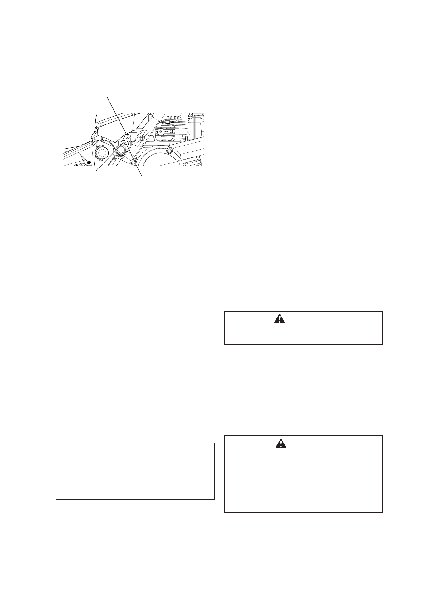
Muffler Spark Arrestor
1. Remove air cleaner cover and remove spark
plug lead.
2. Remove the cutter arm. (See page 30.)
3. Remove spark arrestor screen cover and screen
from muffler body.
4. Clean carbon deposits from muffler components.
5. Replace screen if it is cracked, or has holes
burned through.
6. Assemble components in reverse order.
NOTE
Carbon deposits in muffler will cause drop in
engine output. Spark arrestor screen must be
checked periodically.
Clutch and Maximum Speed Checks
Clutch
Slipping of the clutch under a cutting load is not the only thing that can
happen to a clutch. Another problem may appear during setting of the
Carburetor for proper idling speed. The clutch may be at fault if an adjustment
high enough for stable idling results in wheel rotation. Such a condition
should be checked out by your servicing dealer before any further use of the
saw.
Speed
WARNING
To ensure the wheel does not over speed, the engine no load speed
must be adjusted to a maximum of 9950 rpm. Use a tachometer to
measure speed. If engine speed exceeds 9950 rpm, have the unit ser-
viced by your nearest ECHO servicing dealer before further use.
Whenever activated, the vibration-sensitive governor in the Carburetor high
speed fuel circuit supplies more fuel than the engine can burn. Consequently,
the engine has to purge itself of the extra fuel and slows down in the process.
Proper high speed adjustment (see page 28) of the Carburetor should result
in engine high speed, no load, operation within the desired range. This range
is 9750 rpm ± 200 rpm, which is required for the proper wheel spindle speed
range of 3700 – 3820 rpm.
Cylinder Fins
1. Check periodically.
2. Clogged fins will result in poor engine cooling.
3. Remove dirt and dust from between fins to let
cooling air pass easily.
Bolts
Spark arrestor screen
Spark arrestor screen cover
Cylinder fins
29
CSG-7410
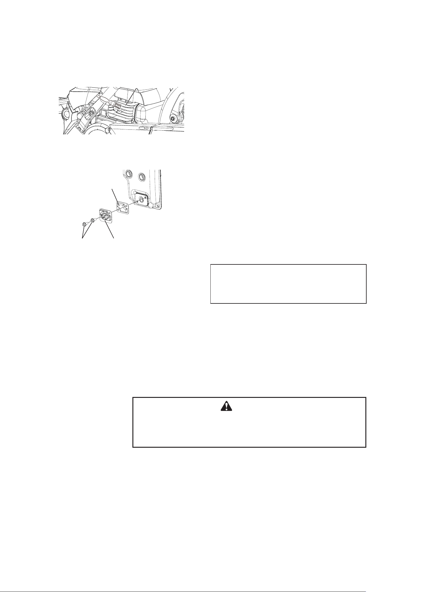
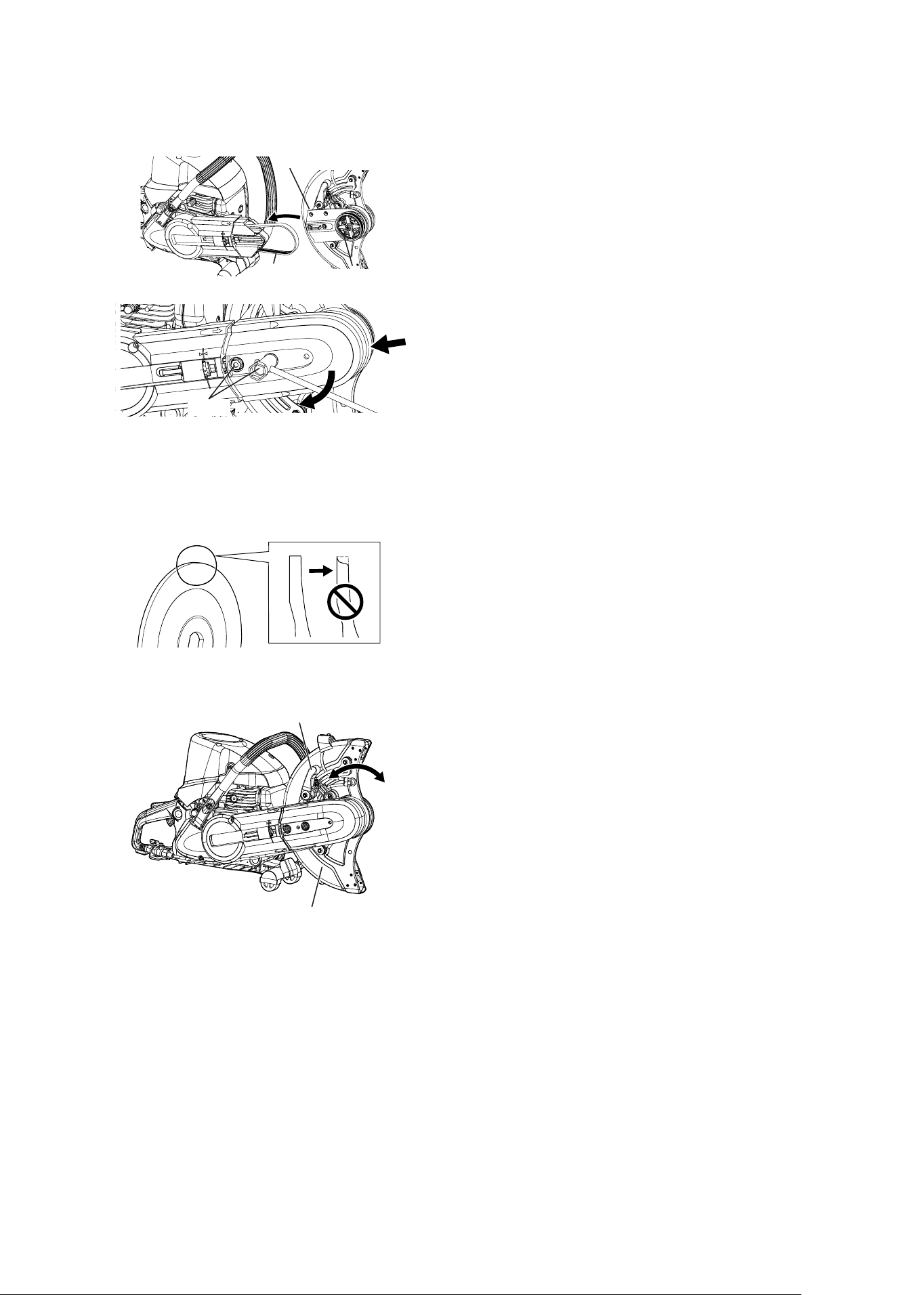
Belt Change and Adjustment
Adjusting the Belt
Adjust the belt if it becomes loose.
1. Loosen the 2 pulley cover bolts about 1 turn.
2. Turn the tension screw so the washer lines up
with the mark on the clutch cover.
3. Tighten the 2 pulley cover bolts. Note: Tighten to
a torque of 23 to 27N・m (230 to 270 kgf・cm).
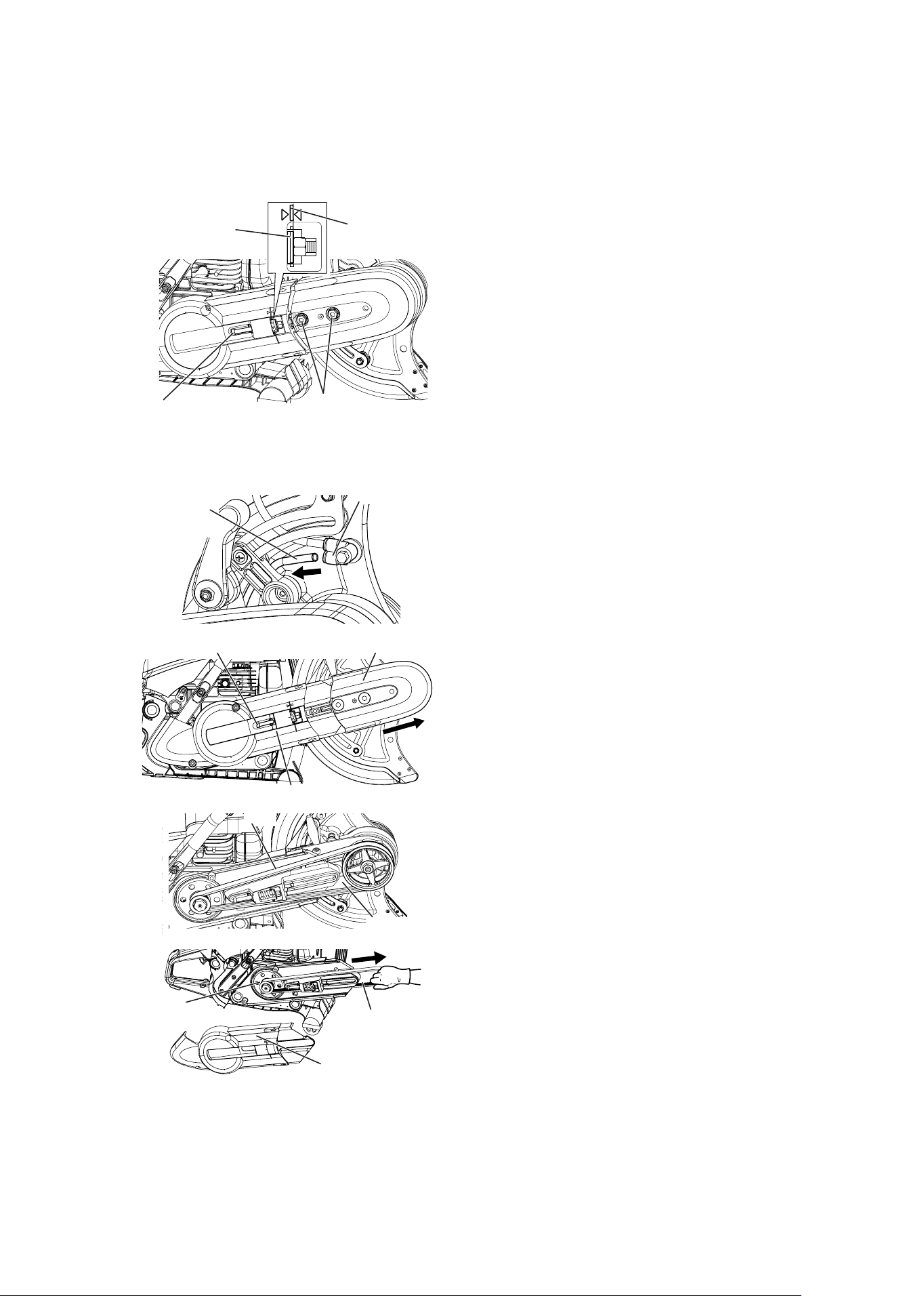
Replacing the Belt
Replace the belt when it becomes very worn
(peeling, turning, cuts, cracking, etc.)
1.Disconnect the water-flush pipe from the pipe
connector.
2. Loosen the tension screw and then remove the
2 pulley cover bolts.
3. Remove the pulley cover along its rail.
4. Loosen the clutch cover bolt and then remove
the clutch cover.
5. Remove the old belt and then remove the cutter
arm.
6. Put the new belt on the small pulley.
7. While pulling the belt in the direction of the cutter,
install the clutch cover and fasten it with its bolt.
Bolt
Tension screw
Washer
Mark
Pulley cover
Tension screw
Clutch cover
Cutter arm
Pulley
(small)
Clutch cover
Belt
Belt
Water-flush
pipe
Pipe connector
30
CSG-7410
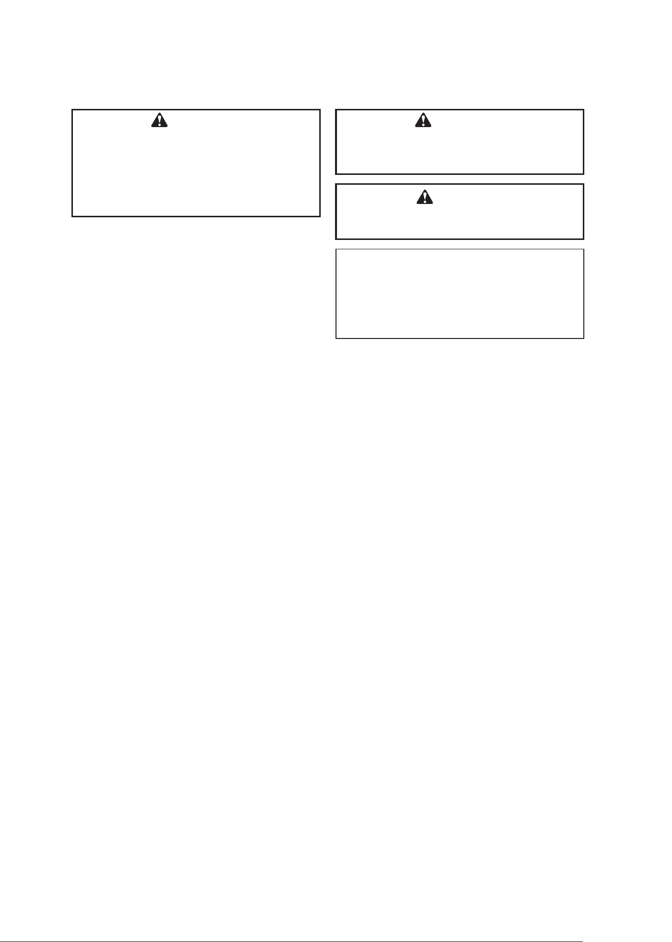
Wheel Guard
1. Make sure it does not touch the cutting wheel, as
a result of deformation or rattling.
2. Consult your dealer if the wheel guard moves
back and forth even when the wheel guard
locking knob is tightened.
3. Consult your ECHO dealer if there is any wear or
cracking.
Flange
1. Check for wear, cracks and broken pieces.
2. Replace with a new one if anything is abnormal.
Wheel guard
Wheel guard locking knob
Bolt
8. Fit the cutter arm into the long hole in the
crankcase and then put the belt on the large
pulley.
9. Put the pulley cover on along the outside of the
cutter arm. Make sure the pulley cover is not
misaligned when putting it into the arm.
10. Tighten the 2 pulley cover bolts and then back
them off 1 turn. Adjust the tightness of the belt.
11. Tighten the 2 pulley cover bolts. Note: Tighten
to a torque of 23 to 27N・m (230 to 270 kgf・cm).
12. Insert the water-flush pipe into the pipe
connector.
13. The belt stretches after being replaced, so
readjust its tension after operating the machine.
Cutter arm
Large pulley
Belt

31
CSG-7410
Troubleshooting Cutting Problems
Troubleshooting Engine Problems
Trouble Probable Cause Remedy
Wheel stops when cutting pressure
is applied
1. Bearing down too hard
2. Binding in crooked cut
3. Binding in closing cut
4. Loose belt
1. Ease up cutting pressure
2. Lay out and follow a straight line
3. Support material so cut will open
4. Increase belt tension
Wheel stops when cutting pressure
is applied
Belt worn beyond the limit Replace belt
Poor cutting – wheel discolored at
outer area
Heat damage
Replace wheel.
Do not cut long in one spot.
Water flush when recommended.
Trouble Probable Cause Remedy
Engine will not start
1. Out of fuel 1. Fill fuel tank
2. Engine flooded 2. Remove spark plug
• Push in and hold the momentary STOP
switch
• Crank the engine to expel the fuel
• Install clean, dry, properly gapped spark plug
3. Fuel filter clogged 3. Install clean fuel filter.
Check that fuel pick-up line is not leaking or
clogged.
Clean fuel tank.
4. Air filter blocked 4. Replace air filter element
5. Spark plug fouled or cracked 5. Replace plug.
6. Ignition magneto or spark
plug wire faulty
6. Contact nearest authorized ECHO servicing
dealer
Engine hard to start
1. See reasons under “will not
start”
1. See remedies above
2. Water in fuel or fuel has gone
stale or sour
2. Fill tank with clean, fresh fuel mixture
3. Engine not getting the proper
fuel / air mixture
3. If over-choked and flooded:
• Remove spark plug
• Push in and hold the momentary STOP
switch
• Crank the engine to expel the fuel
• if not choked enough, set controls properly
for starting
4. Carburetor out of adjustment 4. See “Carburetor Adjustment” or seek
authorized dealer for adjustment
Engine misses
1. Dirt in Carburetor or fuel line 1. Contact nearest authorized servicing dealer
2. Carburetor out of adjustment 2. Adjust, or seek dealer service
3. Weak or intermittent spark 3. Contact nearest authorized servicing dealer
Engine overheats
and / or stalls under
cutting load
1. Not enough oil 1. Use proper amount of oil in fuel mixture
2. Air passages around cylinder
clogged
2. Clean air intake grid on starter side, flywheel,
cylinder fins and surrounding area
3. Carburetor main adjustment
is set too “Lean”
3. See “Carburetor Adjustment” or seek
authorized dealer for adjustment
32
CSG-7410
STORAGE AFTER USE
• Inspect and adjust every part of the engine cut-
off saw.
- Completely clean every part and repair if
necessary.
- Apply thin coating of oil on metal parts to
prevent rust.
• Remove wheel.
• Drain fuel tank, pull starter slowly a few times to
drain fuel from carburetor.
• Pour a small amount of clean motor oil into spark
plug hole, pull starter and crank the engine until
piston reaches: TOP DEAD CENTER.
• Store in a dry area, free from dust.
WARNING
Do not store in an enclosure where fuel
fumes may accumlate or reach an open flame
or spark.
CAUTION
Do not lend or rent your engine cut-off saw
without the Operator's Manual.
NOTE
• For future reference, you should keep this
Operator's Manual.
• If this Operator's Manual has become illegible
or is lost, please purchase a new one from your
ECHO dealer.
WARNING
Momentary stop switch automatically
returns to run position. Engine can start
unintentionally when starter handle is pulled.
Always remove spark plug lead from spark
plug before pulling starter handle, otherwise
severe personal injury may result.

33
CSG-7410
TECHNICAL DATA
* Technical data subject to change without notice.
Model
CSG-7410
External dimensions : Without cutting wheel
Length × Width × Height mm (in) 620 × 240 × 407 (24.4 x 9.4 x 16.0)
Mass : Without cutting wheel and empty tank kg (lb) 10.7 (23.6)
Volume :
Fuel tank mL
(US fl. oz.)
700 (23.67)
Fuel ( Mixture ratio ) 50:1 ratio with ECHO band oil,
ISO-L-EGD (ISO/CD 13738), JASO
M345-FC/FD two-stroke, air-cooled en-
gine oil.
Use 89 octane unleaded. Do not use fuel
containing methyl alcohol, more than
10% ethyl alcohol or 15% MTBE.
Engine :
Type Air-cooled, two-stroke, single cylinder
gasoline engine
Engine displacement
mL (cu.in.)
73.5 (4.49)
Carburetor Diaphragm type, Inner vent type
Magneto Flywheel magneto, CDI type
Spark plug NGK BPMR7A
Starter Recoil starter
Clutch Centrifugal type
Maximum shaft brake power kW 3.2
Wide open throttle speed rpm 9650 (9350-9750)
Idle speed rpm 2800 (2600-3000)
Throttle control Throttle trigger with throttle lockout
Cutting device :
Belt 6PJ-808
Pulley ratio 2.57 : 1
Belt tensioner Coil Spring system
Wheel mm (in.) 350 × 4.7 × 20 (14 x 6/32 x 25/32)
Maximum cut-off wheel speed rpm 3820
Flange outside diameter mm 100
Wheel fastener tightening torque N•m 25 - 30
Maximum spindle speed rating rpm 3820
Sound pressure level : measured at 15 m (50 ft) dB(A) 78.2
Other device :
Vibration reduction system Rubber mounted between the engine
and the handles
34
CSG-7410
WARRANTY REGISTRATION SHEET
Thank you for choosing ECHO Power Equipment
Please go to http://www.echo-usa.com/Warranty/Register-Your-ECHO to register your new product on-line.
It’s FAST and EASY! NOTE: your information will never be sold or misused by ECHO, Inc. Registering
your purchase enables us to contact you in the unlikely event of a service update or product recall, and
verifies your ownership for warranty consideration.
If you do not have access to the Internet, you can complete the form below and mail to:
ECHO Inc., Product Registration, PO Box 1139, Lake Zurich IL 60047.

35
CSG-7410
NOTES

C72715001001 – C72715999999