

ENGLISH j
General-purpose Engine
Owner’s Manual

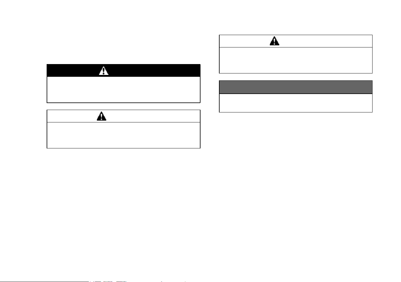
SAFETY AWARENESS
Whenever you see the symbols shown below,
heed their instructions! Always follow safe operat-
ing and maintenance practices.
DANGER
DANGER indicate
s a hazardous situation
which, if not avoided, will result in death or
serious injury.
WARNING
WARNING indica
tes a hazardous situation
which, if not avoided, could result in death
or serious injury.
CAUTION
CAUTION indicates a hazardous situation
which, if not avoi
ded, could result in minor
or mo derate injury.
NOTICE
NOTICE is used to address practices not re-
lated to personal injury.
NOTE
○
This note symbol indicates points of particular in-
terest for more efficient and convenient operation.
READ THE OPERA
TING INSTRUCTIONS OF THE EQUIPMENT THIS ENGINE POWERS.
© 2010 Kawasaki Heavy Industries, Ltd. (1): Nov. 2010. (M)
(6): Apr. 2018. (M)
Kawasaki Motors, Ltd.
READ THIS FIRST
For your safety, read this Owner’s Manual and understand it thoroughly before operating this ENGINE.
DANGER
Exhaust gas contains carbon monoxide, a colorless, odorless poisonous gas. Inhaling carbon
monoxide can cause serious brain injury or death. DO NOT run the engine in enclosed areas. Op-
erate only in a well-ventilated area. Gasoline is extremely flammable and can be explosive under
certain conditions, creating the potential for serious burns. When refueling, servicing fuel system,
draining gasoline and/or adjusting the carburetor: Stop engine and allow it to cool before refueling.
DO NOT smoke. Make sure the area is well-ventilated and free from any source of flame or sparks,
including the pilot light of any appliance.
DO NOT fill the tank so the fuel level rises into the filler neck or level surface of level gauge. If the
tank is overfilled, heat may cause the fuel to expand and overflow through the vents in the tank cap.
Wipe off any spilled gasoline immediately.
Engines can become extremely hot during normal operation. To prevent fire hazard:Keep the en-
gine at least 1 m (3.3 ft) away from buildings, obstructions and other burnable objects. DO NOT
place flammable objects close to the engine. DO NOT expose combustible materials to the engine
exhaust. DO NOT use the engine on any forest covered, brush covered or grass covered unim-
proved land un less spark arrester is installed on the muffler.
To avoid getting an electric shock, DO NOT touch spark plugs, plug caps or spark plug leads during
engine running.
To avoid a serious burn, DO NOT touch a hot engine or muffler. The engine becomes hot during
operation. Before you service or remove parts, stop engine and allow the engine to cool.
DO NOT place hands or feet near moving or rotating parts. Place a protective cover over pulley, V
belt or coupling.
DO NOT run engine at excessive speeds. This may result in injury.
Always remove the spark plug caps from spark plugs when servicing the engine to prevent acci-
dental starting.
Read warning labels which are on the engine and understand them. If any label is missing, damaged, or
worn get a replacement from your Kawasaki engine dealer and install it in the correct position.

FOREWORD
This Owner’s Manual provided to aid you in the safe and reliable operation of your Engine. READ AND
UNDERSTAND IT THOROUGHLY BEFORE OPERATING YOUR ENGINE.
READ THE OPERATING INSTRUCTIONS OF THE EQUIPMENT TH IS ENGINE POWERS.
To ensure a long, trouble-free life for your Engine, give it proper care and maintenance in accordance with
this Owner’s Manual.
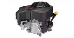
Please note that the photographs and illustrations shown in this manual are made based on Model FR600V
as a typical example among other similar models.
All rights reserved. No part of this publication m ay be reproduced, stored in a retrieval system, or transmitted
in any form or by any means, electronic mechanical photocopying, recording or otherwise, without the prior
written permission of Kawasaki Heavy Industries, Ltd., Consumer Products & Machinery Company. Although
every possible care has been taken to make this manual as complete and accurate as possible, Kawasaki
cannot guarantee against errors and omissions. Due to improvements in design and performance during pro-
duction, procedures and specifications are subject to change without prior notice. Illustrations a re provided for
general reference purposes, and may differ from actual product aspects and components.
All rights reserved. No part of this publication may be reproduced, stored in a retrieval system, or transmitted
in any form or by any means, electronic mechanical photocopying, recording or otherwise, without the prior
written permission of Kawasaki Motors, Ltd.. Although every possible care has been taken to make this manual
as complete and accurate as possible, Kawasaki cannot guarantee against errors and omissions. Due to
improvements in design and performance during production, procedures and specifications are subject to
change without prior notice. Illustrations are provided for general reference purposes, and may differ from actual
product aspects and components.

TAB L E OF CONTENTS
GENERAL INFORMATION.............................. 5
Label Location ............................................... 5
Parts Location . ............... ............... ............... . 6
Tune-up S pecifications ... ............... ............... . 7
Engine Oil Capacity ....................................... 8
FUEL AND OIL RECOMMENDATIONS .......... 9
Fuel ............................................ ............... .... 9
Engine Oil ...................................................... 10
PREPARATION.............. ............... ................... 11
Fuel ............................................ ............... .... 11
Engine Oil ...................................................... 11
STARTING ....................................................... 13
Starting the Engine ........................ ............... . 13
OPERATING ........................ ............................ 15
Warming Up................................................... 15
Engine Inclination ......................................... . 16
STOPPING ....................................... ............... . 17
Stopping the Engine ...................................... 17
Emergency Stop......................................... 17
ADJUSTMENT .............................. ............... .... 18
Throttle Cable Installation, Adjustment.......... 18
Choke Cable Installation, Adjustment ........... 18
Engine Speed Adjustment............................. 20
MAINTENANCE ............................................... 21
Periodic Maintenance Chart ................ ......... 21
Oil Level Ch eck ..................... ........................ 23
Oil Change ................................................. ... 24
Oil Filter Change ........................................... 25
Air Cleaner Serv ice ............ ........................... 26
Air Cleaner Element .................................. 26
Spark Plug Service...................... .................. 2 7
Fuel Filter and Fuel Pump Serv ice ................ 28
Cooling Syst em Cleaning .............................. 29
STORAGE.................... ............... ..................... 31
Fuel System Dr aining .................................... 31
TROUBLESHOOTING GUIDE. ............... ......... 33
ENVIRONMENTAL PROTECTION.................. 35
SPECIFICATIONS............................................ 36
WIRING DIAGRAM............... ............... ............ 37
Wiring Diagram...................... ............... ......... 37
7
7
8
9
10
11
11
12
13
13
13
15
15
17
17
18
19
19
19
20
20
20
22
23
23
25
26
27
28
28
29
30
31
33
33
35
37
38
39
39
GENERAL INFORMATION 5
GENERAL INFORMATION
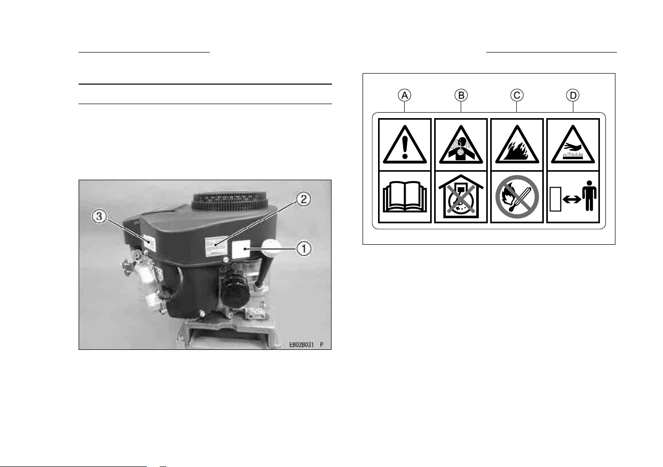
Label Location
The engine serial number is your only means of
identifyin g your particular engine from others of the
same model type.
This engine serial number is needed by your
dealer when ordering parts.
1. Warning Label
2. Important Engine Information Label
3. Engine Serial Number Label
Warning Label
A.TheOwner’smanualcontainsimportantinformation
onsafeoperation.Readitbeforeoperatingengine.
B.Exhaustgascontainscarbonmonoxide,an
odorlessanddeadlypoison.
DonotrunEngineinanenclosedarea.
C.Gasolineisextremelyammableandexplosive.
Noopenamesorothersourceofignition.
D.Enginescanbecomeextremelyhotduringnormal
operation.Keepawayfromhotpartsoftheengine.
7
6 GENERAL INFORMATION
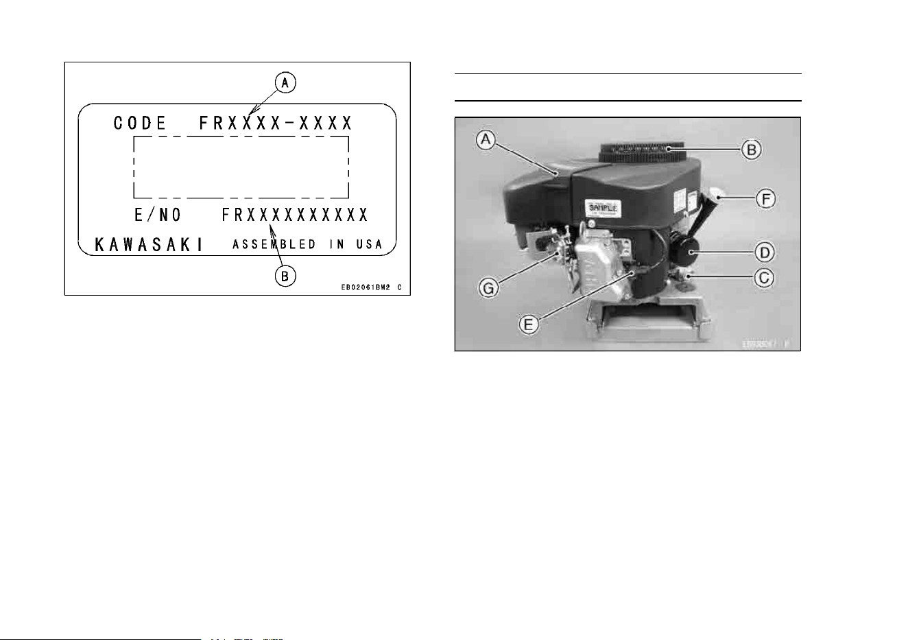
A. Model Code
B. Engine Serial Number
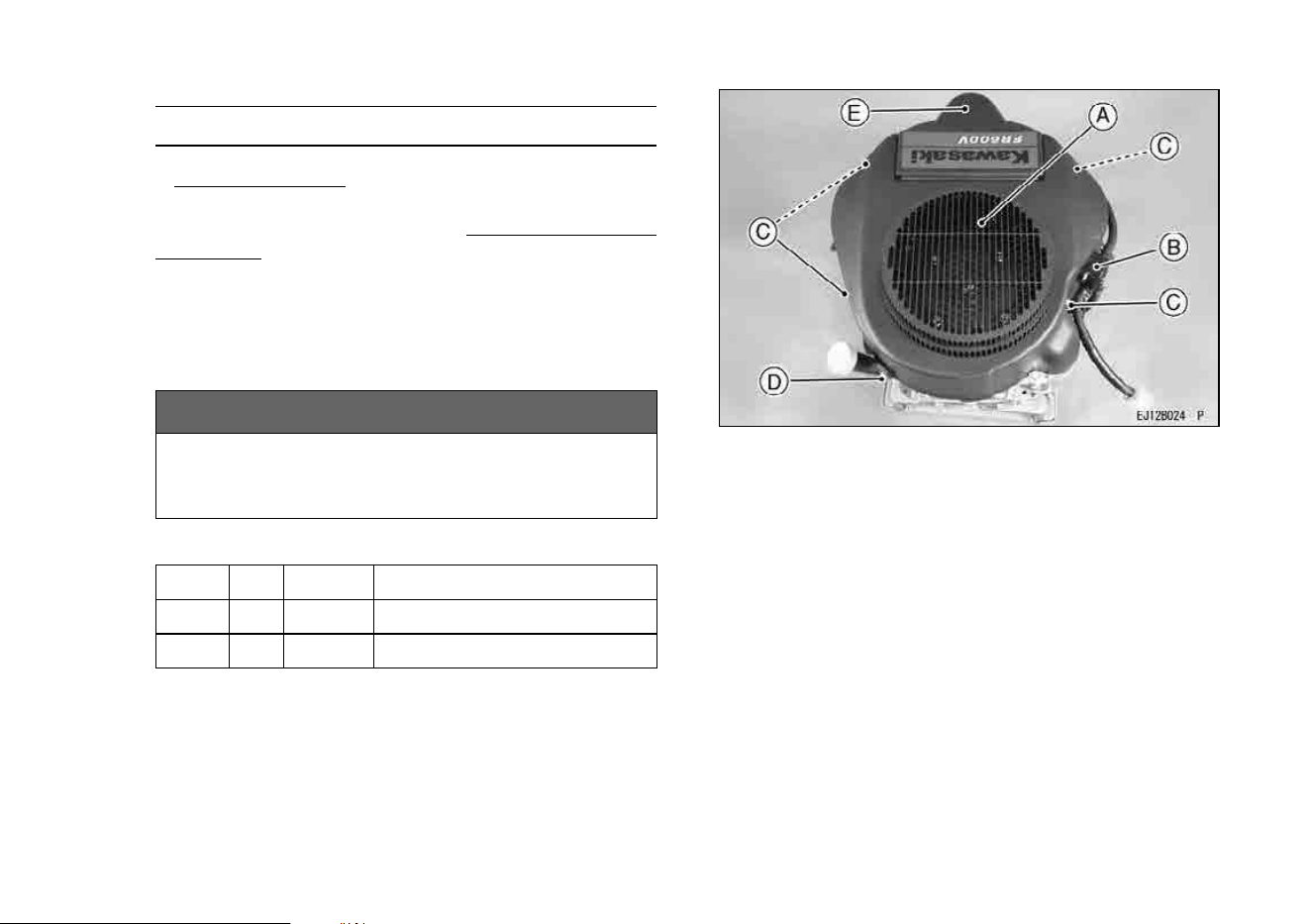
Parts Location
A. Air Cleaner (inside A)
B. Air Inlet Guard
C. Oil Drain Plug
D. Oi l Filter
E. Spark Plugs/Spark Plug Caps
F. Oil Gauge/Filler Cap
G. Control Panel
8
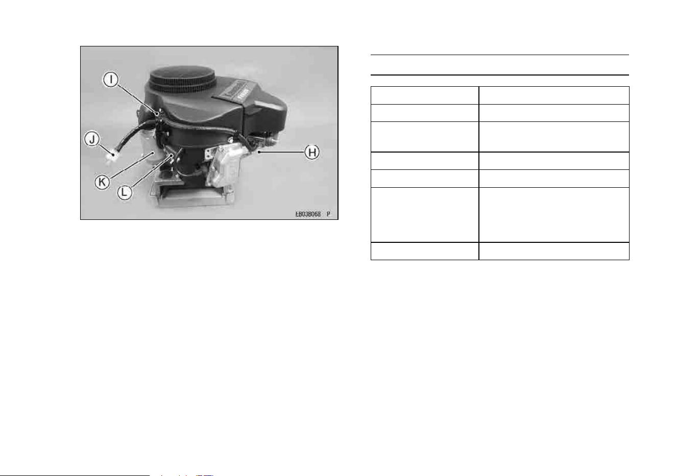
GENERAL INFORMATION 7
H. Carburetor
I. Fuel Pump
J. Fuel Filter
K. Electric Starter
L. Voltage Regulator
Tune-up Specifications
ITEM
Specifications
Ignition Timing Unadjustable
Spark Plugs:
Gap
NGK BPR4ES
0.75 mm (0.030 in.)
Low Idle Speed 1550r/min(rpm)
High Idle Speed 3600r/min(rpm)
Valve Clearance
In 0.10 ∼ 0.15 mm
(0.004 ∼ 0.006 in.)
Ex 0.10 ∼ 0.15 mm
(0.004 ∼ 0.006 in.)
Other Specifications
No other adjustment needed
NOTE
○
High and low idle speeds may vary depending on
the equipment on which the engine is used. Refer
to the equipment specification.
9

8 GENERAL INFORMATION
Engine Oil Capacity
Engine Oil Capacity
1.5 L
[when oil filter is not removed]
FR541V
FR600V
1.7 L
[when oil filter is removed]
GENERALINFORMATION
10
FUEL AND OIL REC OMMENDATIONS 9
FUEL AND OIL RECOMMENDATIONS
Fuel
Use only clean, fresh, unleaded regular grade
gasoline.
NOTICE
Do not mix oil with gasoline.
Octane Rating
The octane rating of a gasoline is a measure of
its resistance to “knocking”. Using a minimum of 91
octane by the RON is recommended.
RON = Research Octane Number
NOTE
○
If “knocking or pinging” occurs, use a different
brand of gasoline or higher octane rating.
Oxygenated Fuel
Oxygenates (either ethanol or MTBE) are added
to the gasoline. If you use the oxygenated fuel be
sure it is unleaded and meets the minimum octane
rating requirement.
The following are the EPA approved percentages
of fuel oxygenates.
ETHANOL: (Ethyl or Grain Alcohol)
You may use gasoline containing up to 10%
ethanol by volume.
MTBE: (Methyl Tertiary Butyl Ether)
You may use gasoline containing up to 15% MTBE
by volume.
METHANOL: (Methyl or Wood Alcohol) 5% by vol-
ume
You may use gasoline containing up to 5%
methanol by volume, as long as it also contains
cosolvents and corrosion inhibitors to protect the
fuel system. Gasoline containing more than 5%
methanol by volume may cause starting and/or
performance problems. It may also damage metal,
rubber, and plastic parts of your fuel system.
FUELANDOILRECOMMENDATIONS
11
10 FUEL AND OIL RECOMMENDATIONS
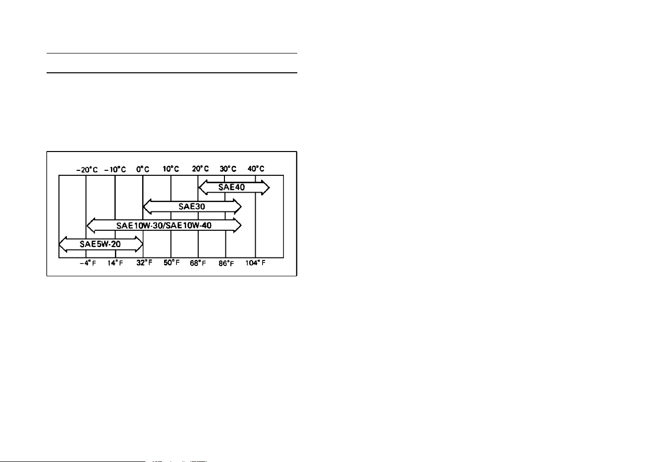
Engine Oil
The following engine oils are recommended.
API Service Classification : SJ or hig her class.
Oil Viscosity
Choose the viscosity according to the temperature
as follows :
NOTE
○
Using multi grade oils (5W-20, 10W-30, and 10W
-40) will increase oil consumption. Check oil level
more frequently when using them.
12
PREPARATION 11
PREPARATION
Fuel
WARNING
Gasoline is extremely flammable and can be
explosive under certain conditions, creating
the potential for serious burns. When refuel-
ing, servicing fuel system, draining gasoline
and/or adjusting the carburetor: Stop engine
and allow it to cool before refueling. DO NOT
smoke. Make sure the area is well-ventilated
and free from any source of flame or sparks,
including the pilot light of any appliance. DO
NOT fill the tank so the fuel level rises into the
filler neck or level surface of level gauge. If
the tank is o verfilled, heat m ay cause the fuel
to expand and overflow through the vents in
the tank cap. Wipe off any spilled gasoline
immediately.
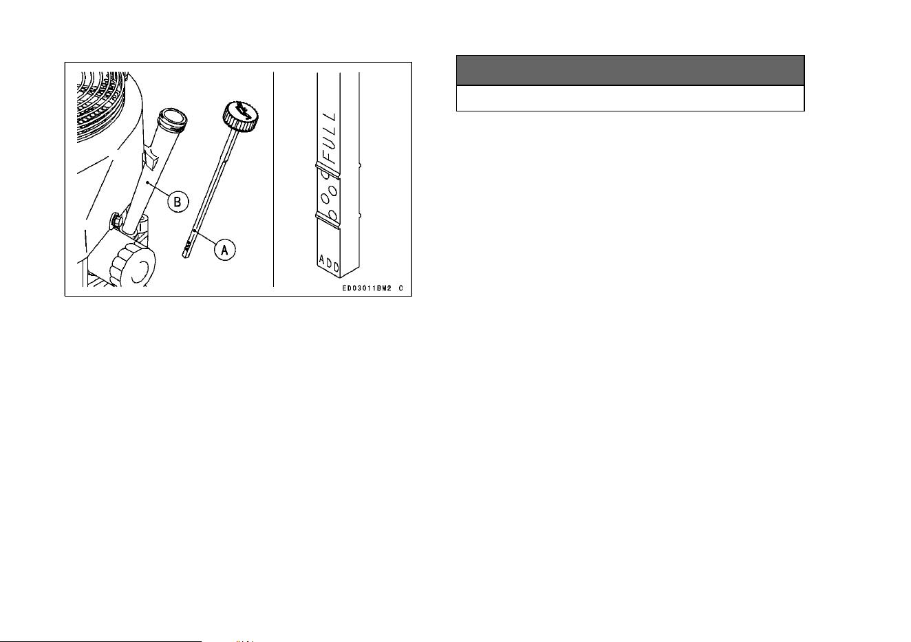
Engine Oil
Check the engine oil daily before starting the en-
gine otherwise shortage of the engine oil may c ause
serious damage to the engine such as seizure.
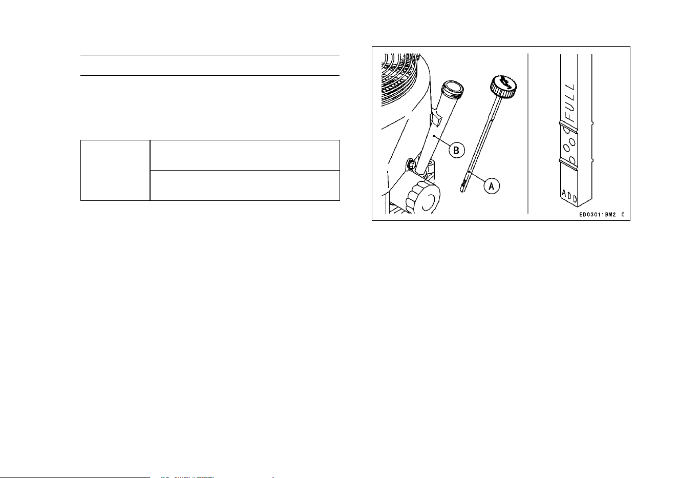
•
Place the engine on level surface. Clean area
around the oil gauge before removing it.
•
Remove the oil gauge and wipe it with a clean
cloth.
•
Pour the oil slowly to “FULL” mark on the oil gauge.
•
Insert the oil gauge into tube WITHOUT SCREW-
ING IT IN.
•
Remove the oil gauge to check the o il level. The
level should be between “ADD” and “FULL” marks.
Do not overfill.
•
Install and tighten the oil gauge.
NOTICE
Do not fill above the “FULL” mark. Excess
oil will cause a smoking condition, and may
cause the engine to overheat.
Engine Oil Capacity
1.5 L
[when oil filter is not removed]
FR541V
FR600V
1.7 L
[when oil filter is removed]
13
12 PREPARATION
A. Oil Gauge
B. Tube
NOTICE
The engine is shipped without engine oil.
14
STARTING 13
STARTING
Starting the Engine
WARNING
Exhaust gas contains carbon monoxide, a
colorless, odorless poisonous gas. Inhal-
ing carbon monoxide can cause serious
brain injury or death. DO NOT run the en-
gine in enclosed areas. Operate only in a
well-ventilated area.
WARNING
Engine exhaust may ignite combustible ma-
terials and cause a fire.
Keep the area around the exhaust outlet
clear. Locate the unit so that the exhaust
outlet points toward an open area and is
located at least one meter (3.3 feet) from any
obstructions.
NOTE
○
Be aware of the following in order to start the en-
gine easily in cold weather.
○
Use proper oil for expected temperature (See
“FUEL AND OIL RECOMMENDATIONS” chap-
ter).
Use fresh gasoline.
Protect the engine or the equipment from direct
exposure to weather when not in operation.
NOTE
○
Follow the operating instructions of the equipment
this engine powers.
•
Before starting the engine, disconnect all possible
external loads.
Open the fuel valve on the equipment.
Move throttle lever on dash to half throttle position.
Use full choke w
hen the engine is cold, but in hot
weather or w
hen th e engine is already w arm, use
half choke or leave the choke fully open.
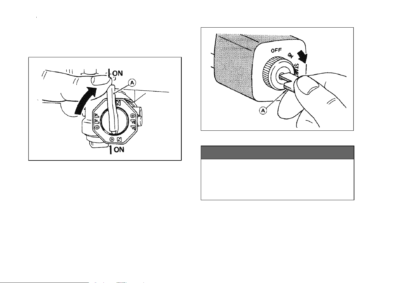
•
Put the switch key into the engine switch.
•
Turn the switch k ey to the S TART position on the
equipment. Usually engine will start within 3 sec-
onds.
NOTICE
Do not run the electric starter continuously
for more than 5 seconds, otherwise the bat-
tery may discharge quickly. If the engine
does not start right away, wait 15 seconds
and try again.
NOTE
○
When the engine is very warm, or when the engine
does not start immediately, DO NOT keep trying
15
14 STARTING
to start it with the choke closed as this will cause
flooding and make starting more difficult.
○
Instead, fully open the choke and start the engine.
A. Fuel Valve
A. Switch Key
NOTICE
Whenever you start engine, make sure warn-
ing lamp is not illuminated after engine
starts. If warning lamp comes on, stop
engine immediately and check oil level (If
equipped).
•
After starting the engine, gradually return the
choke lever to the fully open position.
16
OPERATING 15
OPERATING
Warming Up
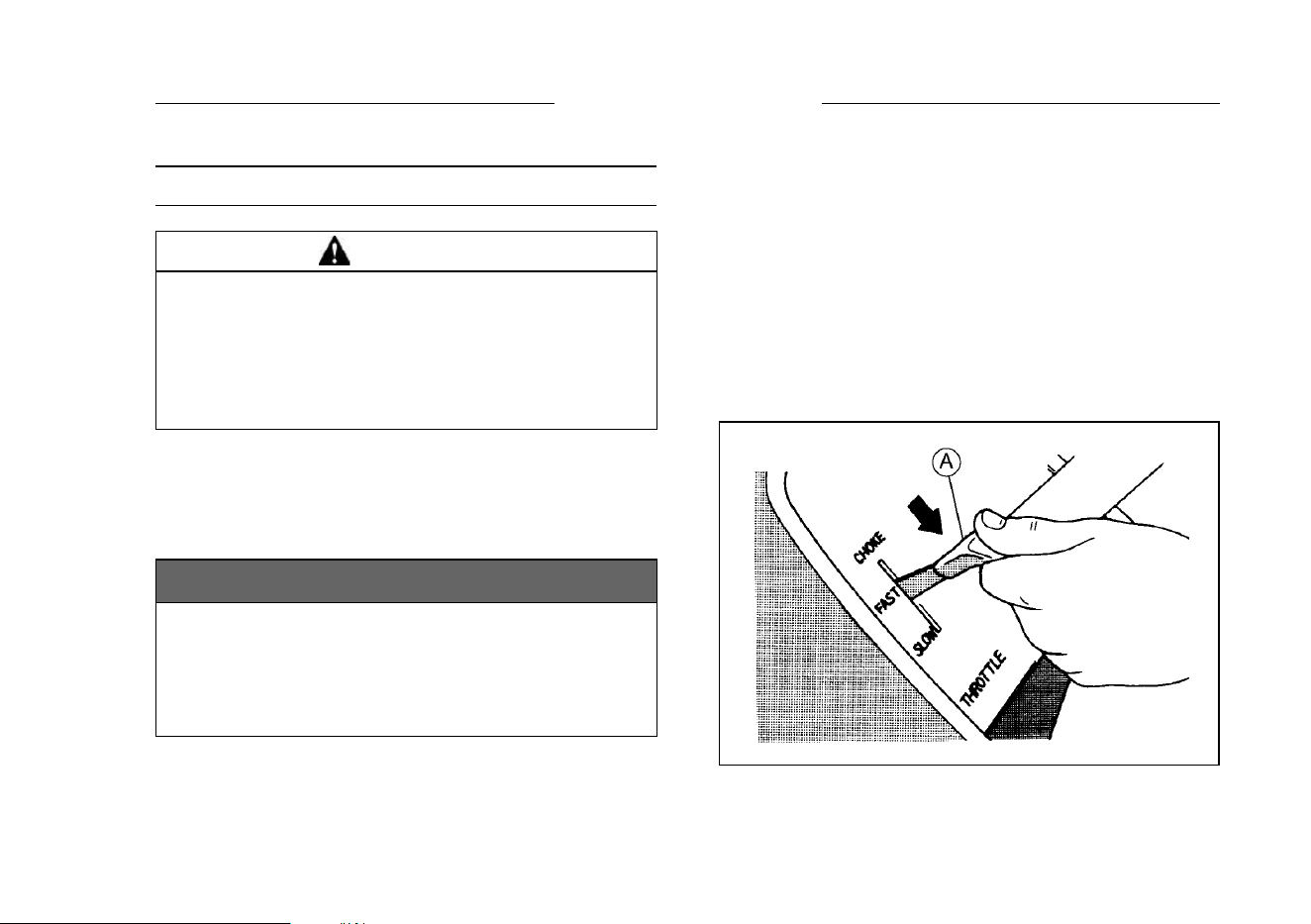
After the engine starts, move the throttle lever
on the equipment to halfway between “FAST” and
“SLOW”.
To warm up the engine, run it for 3 to 5 minutes
with the throttle lever in the same load position
(halfway) before putting the equipment under load.
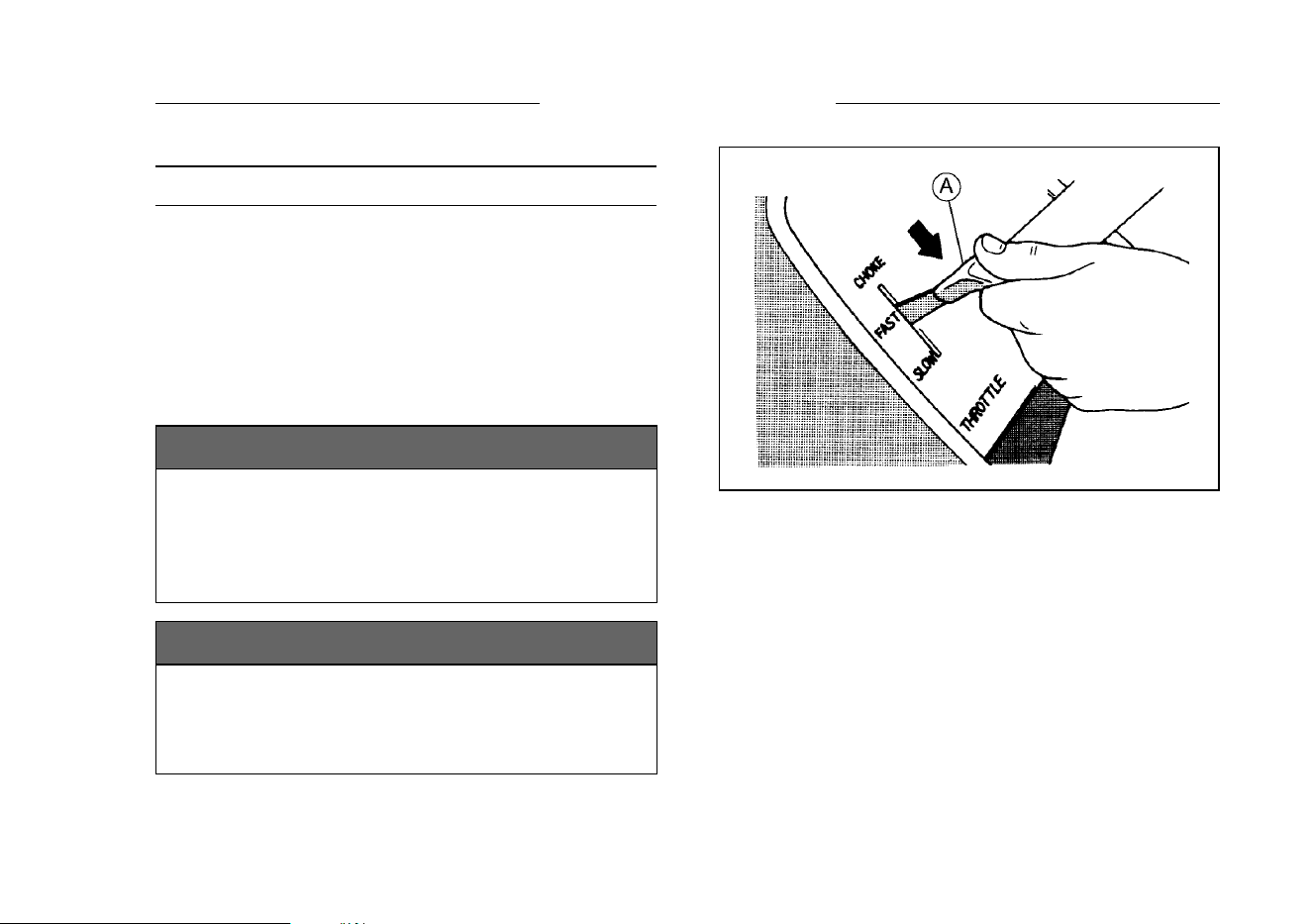
Then, move the throttle lever (A) on the equipment
to its “FAST” position.
NOTICE
Allow engine to warm up sufficiently (3 to 5
minutes at idle) before applying a load. This
will allow oil to reach all engine parts, and
allow piston clearance to reach design spec-
ifications.
NOTICE
While warming up the engine, make sure the
warning lamp (oil pressure) on dash is not
on. The warning lamp must not be illumi-
nated during engine operation (if equipped).
A. Throttle Lever
17
16 OPERATING
Engine Inclination
This engine will operate continuously at angles up
to 25° in any direction.
Refer to the operating instructions of the equip-
ment this engine powers. Because of equipment
design or application, there may be more stringent
restrictions regarding the angle of operation.
NOTICE
Do not operate this engine continuously at
angles exceeding 25° in any direction. En-
gine damage could result from insufficient
lubrication.
18
STOPPING 17
STOPPING
Stopping the Engine
WARNING
Leaving the equipment with the key hanging
in the ignition can allow operation by some-
one who does not know how to operate it. It
may cause serious accident with injury. Al-
ways remove the key from unattended equip-
ment.
Ordinary Stop
•
Move the throttle lever to “slow” position.
•
Lower the engine speed to the idle speed. Keep
running at the idle speed for about one minute.
NOTICE
Engine damage can occur from run-on or
after-burning if engine is stopped suddenly
from high speed loaded operation. Reduce
engine speed to idle for one minute before
shutting engine off.
•
Turn the engine switch or the switch key to “OFF”
position.
For Control Panel Switch Type, move the throttle
lever against its low speed end to turn the ignition
off.
Emergency Stop
•
Immediately turn the engine switch or the switch
key to “OFF” position.
Close the fuel valve on the equipment.
For Control Panel Switch Type, move the throttle
lever on the equipment to its low speed end. Moving
the lever to its low speed end turns ignition off.
A. Throttle Lever
19

18 ADJUSTMENT
ADJUSTMENT
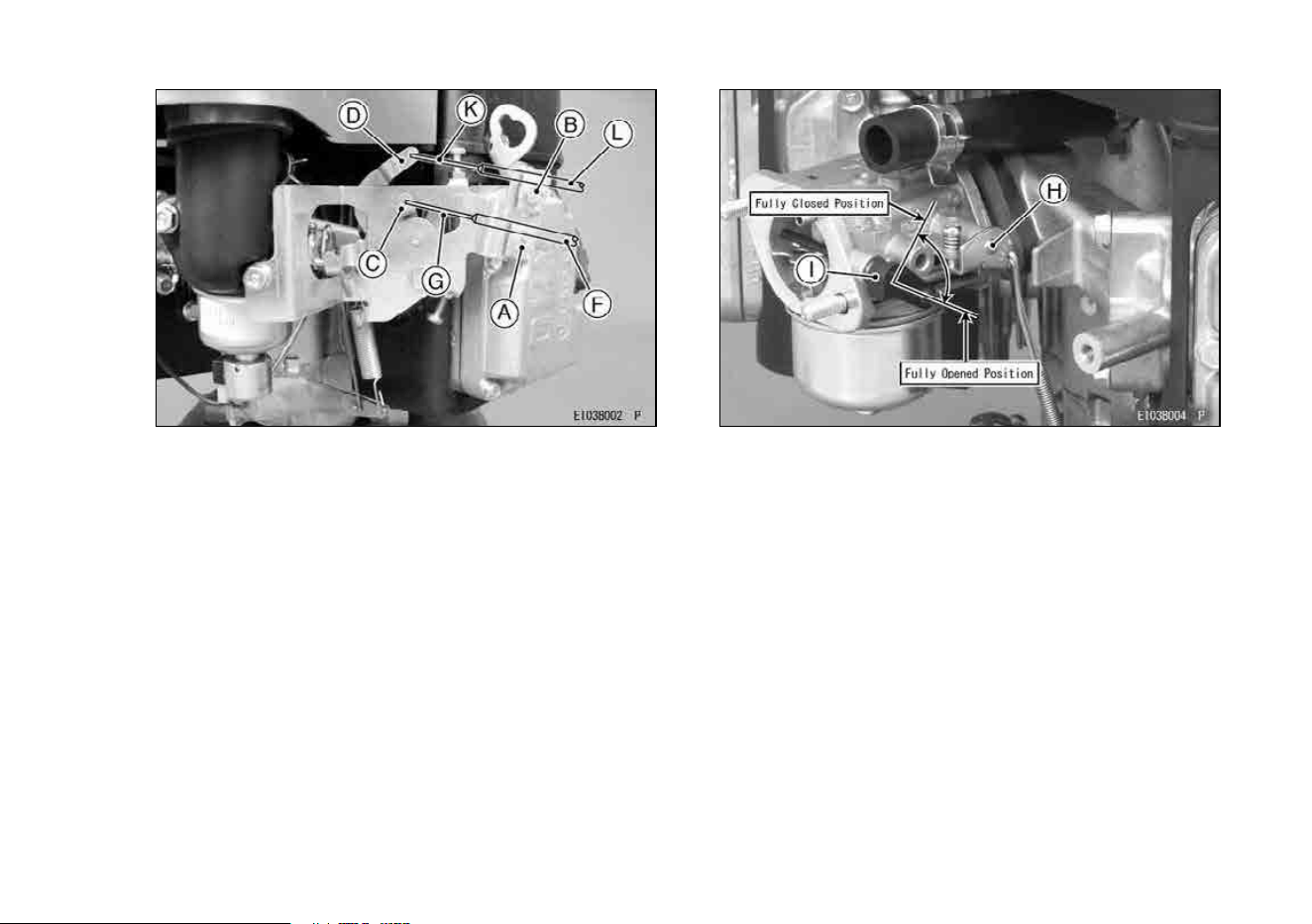
Throttle Cable Installation, Adjustment
•
Link the throttle cable to the speed control lever
and loosely clamp the throttle cable outer housing
with the cable clamp bolt.
Move the throttle lever to “FAST” position.
Pull up the outer housing of the throttle cable until
the inner wire has almost no slack, and tighten the
cable clamp bolt.
Move the throttle lever to “SLOW” posit ion. Make
sure that the carburetor throttle valve is m oved
smoothly.
Choke Cable Installation, Adjustment
•
Link the choke cable to the choke control lever,
and loosely clamp the choke cable outer housing
with the cable clamp bolt.
Move the equipment choke control to “OPEN” po-
sition. Make sure that the carburetor choke valve
is fully opened.
Pull up the outer housing of the choke cable until
the inner wire has almost no slack, and tighten the
cable cla mp bolt.
Move the equipment choke control to “CHOKE”
position. Make sure that the carburetor choke
valve is completely closed.
Make sure that the c hoke valve turns from fully
closed position to fully opened position when ac-
tuating the equipment choke control.
20
ADJUSTMENT 19
A. B. Cable Clamp Bolt
C. Speed Control Lever
D. Choke Control Lever
F. Throttle Cable Outer Housing
G. K. Inner Wire
L. Choke Cable Outer Housing
H. Throttle Valve
I. Chok e Valve
21

20 ADJUSTMENT
Engine Speed Adjustment
NOTE
○
Do not tamper with the governor setting or the car-
buretor setting to increase the engine speed. Ev-
ery carburetor is adjusted at the factory and a cap
or stop plate is installed on each mixture screw.
○
If any adjustment is necessary, it must be per-
formed by your authorized Kawasaki Engine
dealer.
22
MAINTENANCE 21
MAINTENANCE
Maintenance, replacement, or repair of the emission control devices and systems may be performed
by any nonroad engine repair establishment or individual.
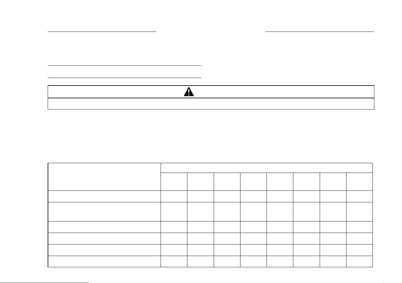
Periodic Maintenance Chart
WARNING
Prevent accidental starting during engine service by removing the spark plug caps.
NOTE
○
The service intervals can be used as a guide. Service more frequently as necessary by operating conditions.
♦ : Service more frequently under dusty conditions.
K:Service to be performed by an authorized Kawasaki dealer.
INTERVAL
MAINTENANCE
Daily
First
8 hr.
Every
25 hr.
Every
50 hr.
Every
100 hr.
Every
200 hr.
Every
250 hr.
Every
300 hr.
Every
500 hr.
Check and add engine oil.
•
Check for loose or lost nuts and
screws.
•
Check for fuel and oil leakage.
•
Check battery electrolyte level.
•
♦
Check or clean air inlet screen.
•
♦
Clean air cleaner paper element.
•
MAINTENANCE
INTERVAL
Daily
Every
25 hr.
Every
50 hr.
Every
100 hr.
Every
200 hr.
Every
250 hr.
Every
300 hr.
Every
500 hr.
Check and add engine oil.
●
Check for loose or lost nuts and
screws.
●
Check for fuel and oil leakage.
●
Check battery electrolyte level.
●
◆
Check or clean air inlet screen.
●
◆
Clean air cleaner paper element.
●
23
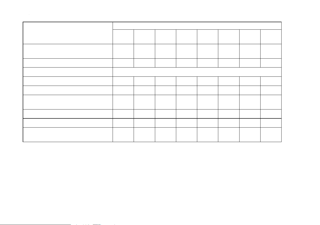
22 MAINTENANCE
INTERVAL
MAINTENANCE
Daily
First
8 hr.
Every
25 hr.
Every
50 hr.
Every
100 hr.
Every
200 hr.
Every
250 hr.
Every
300 hr.
Every
500 hr.
♦
K
Clean dust and dirt from cylinder
and cylinder head fins.
•
Tighten nuts and screws.
•
Change engine oil.
• •
Clean and regap spark plugs.
•
Change oil filter.
•
♦
Replace air cleaner paper
element
•
K
Clean combustion chamber.
•
K
Check and adjust valve clearance.
•
K
Clean and lap valve seating
surface.
•
MAINTENANCE
INTERVAL
Daily
Every
25 hr.
Every
50 hr.
Every
100 hr.
Every
200 hr.
Every
250 hr.
Every
300 hr.
Every
500 hr.
◆
K
Clean dust and dirt from cylinder
and cylinder head ns.
●
Tighten nuts and screws.
●
Change engine oil. Every 100 hours or 1 year whichever comes rst
Clean and regap spark plugs.
●
Change oil lter.
●
◆
Replace air cleaner paper
element.
●
K Clean combustion chamber.
●
K Check and adjust valve clearance.
●
K
Clean and lap valve seating
surface.
●
24
MAINTENANCE 23
Oil Level Check
Check oil le vel daily an d before each time of oper-
ation. Be sure oil level is maintained. See “PREPA-
RATION” chapter.
Engine Oil Capacity
1.5 L
[when oil filter is not removed]
FR541V
FR600V
1.7 L
[when oil filte r is removed]
A. Oil Gauge
B. Oil Filler Tube
25
24 MAINTENANCE
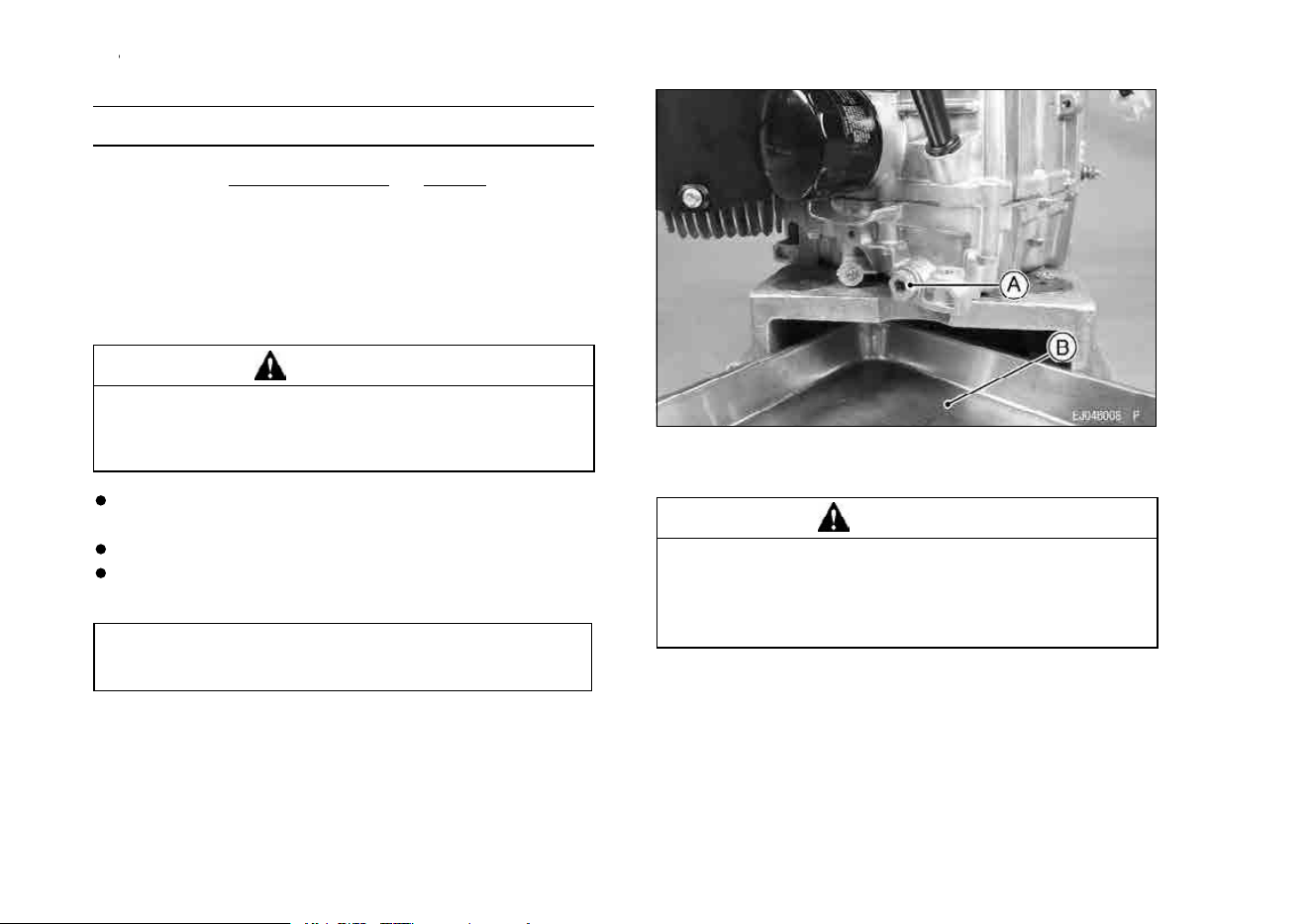
Oil Change
Change oil after first 8 hours of operation.There-
after change oil e
very 100 hours.
•
Run the engine to warm oil.
Be sure the engine (equipment) is level.
Stop the engine.
Remove the oil drain plugs a nd d rain the oil into
suitable container while engine is warm.
WARNING
Hot engine oil can cause severe burns.
Allow engine temperature to drop from hot to
warm level before draining and handling oil.
•
Install the oil drain plugs.
Remove oil gauge and refill with fresh oil (See
“FUEL AND OIL RECOMMENDATIONS” chap-
ter).
Check the oil level (See “PREPARATION” chapter
for oil level check).
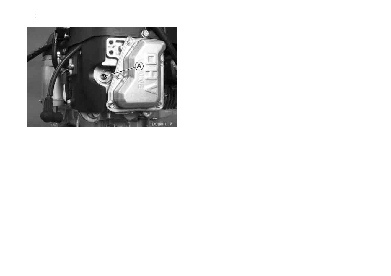
A. Oil Drain Plug
B. Suitable Container
WARNING
Engine oil is a toxic substance. Dispose of
used oil properly. Contact your local author-
ities for approved disposal methods or pos-
sible recycling.
Remove the oil drain plug and drain the oil into
suitable container while engine is warm.
Change oil every 100 hours or 1 year whichever
comes rst.
Replace the O-ring of the oil drain plug with a new
one.
Apply grease to the O-ring.
Tighten the oil drain plug.
Tightening Torque
Oil Drain Plug:
6.9 N·m (0.70 kgf·m, 61 in·lb)
Remove oil gauge and refill with fresh oil (See
“FUEL AND OIL RECOMMENDATIONS” chap-
ter).
Check the oil level (See “PREPARATION” chapter
for oil level check).
26
MAINTENANCE 25
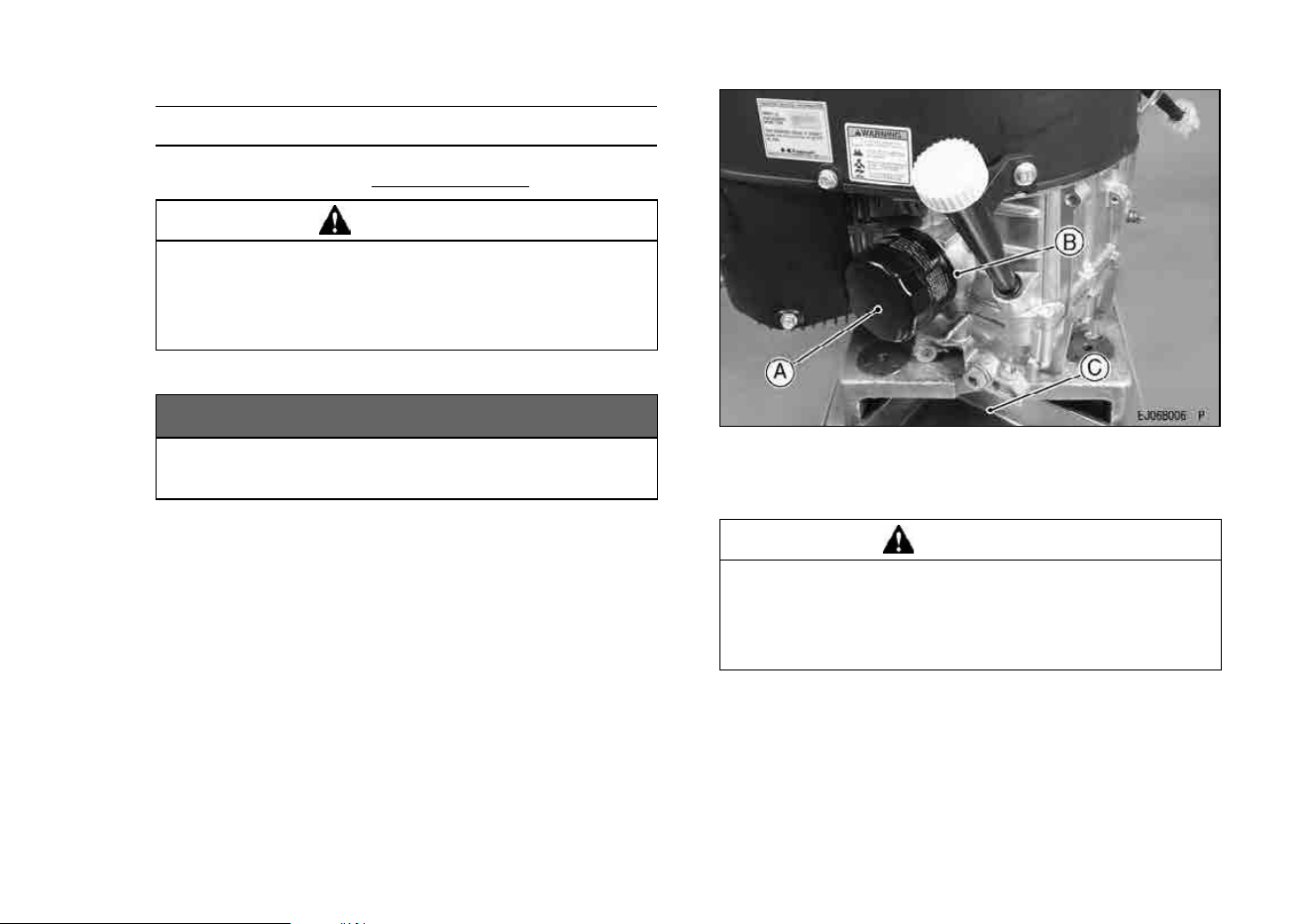
Oil Filter Change
•
Change the oil filter every 200 hours of operation.
WARNING
Hot engine oil can cause severe burns.
Allow engine temperature to drop from hot to
warm level before attempting to remove oil
filter.
•
Drain engine oil into a suitable container.
NOTICE
Before remo ving the oil filter, place suitable
pan under filter connection.
•
Rotate the oil filter counterclockwise to remove it.
Coat a film of clean engine oil on seal of new filter.
Install new filter rotating it clockwise until s eal con-
tacts mounting surface. Then rotate filter 3/4 turn
more by hand.
Supply engine oil as specified.
Run the engine for about 3 minutes, stop engine,
and check oil leakage around the filter.
Add oil to compensate for oil level drop due to oil
filter capacity (See “PREPARATION” chapter for
oil lev el check).
A. Oil Filter
B. Mounting Surface
C. Suitable Container
WARNING
Engine oil is a toxic substance. Dispose of
used oil properly. Contact your local author-
ities for approved disposal methods or pos-
sible recycling.
27
26 MAINTENANCE
Air Cleaner Service
NOTICE
To prevent excessive engine wear, do not run
the engine with the air cleaner removed.
Air Cleaner Element
Lift the air cleaner cover and loose nuts. Remove
the air cleaner element.
Clean the paper element e
very 100 hours.
•
Clean the paper element by tapping gently to re-
move dust. If very dirty, replace the paper element
with a new one.
R
eplace with a new paper element yearly or 200
hours. Whichever comes first.
A. Air Cleaner Cover
B. C. Nut
D. Air Cleaner Element
NOTE
○
Operating in dusty condition may require more fre-
quent maintenance than above.
NOTICE
Do not wash paper element.
Do not oil paper element.
Do not use pressurized air to clean paper el-
ement.
28
MAINTENANCE 27
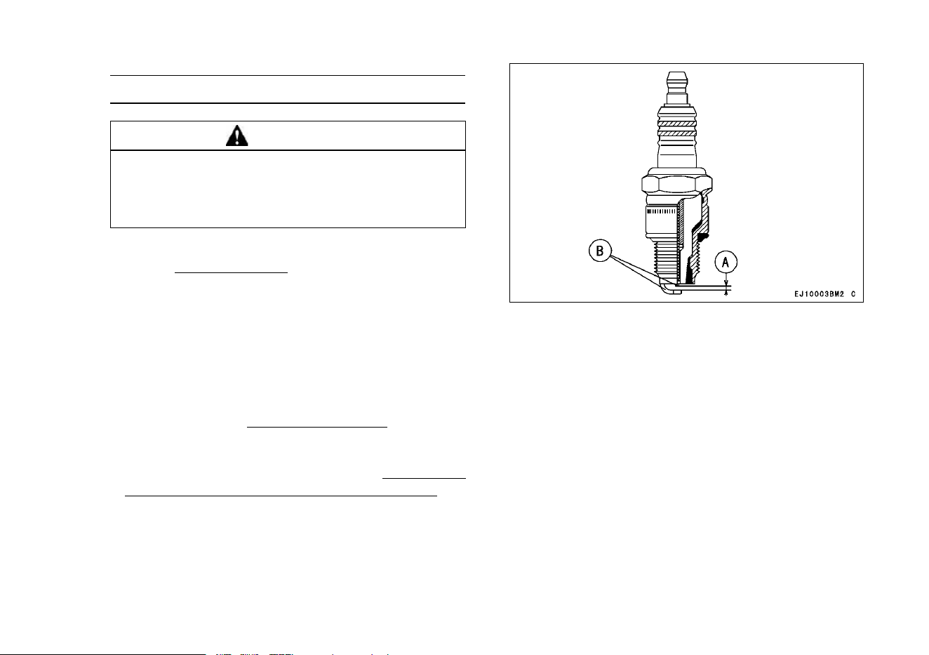
Spark Plug Service
WARNING
Engines can become extremely hot during
normal operation. Hot engine components
can cause severe burns. Stop the engine and
allow it to cool before checking spark plugs.
Clean or replace the spark plugs and reset spark
plug gap e
very 100 hours of operation.
•
Disconnect the spark plug caps from the spark
plugs and remove the spark plugs.
Clean the electrodes by scraping with a wire brush
to remove carbon deposits.
Inspect for cracked porcelain or other wear and
damage. Replace the spark plug with a new one
if necessary.
Check the spark plug gap and reset if necessary.
The gap must be 0
.75 m m (0.030 in.). To change
the gap, bend only the side–electrode, using a
spark plug tool.
Install and tighten the spark plugs to 2
2 N·m (2.2
kgf·m, 16 ft·lb). Connect the sp a rk plug caps.
RECOMMENDED SPARK PLUG
NGK ..................................BPR4ES
A. Spark Plug Gap
B. Electrodes
29
28 MAINTENANCE
Fuel Filter and Fuel Pump Service
WARNING
Many solvents are highly flammable and may
cause serious burns. Improper use of sol-
vents can result in fire or an explosion. Do
not use gasoline or low flash-point solvents
to clean the fuel filter and/or the fuel pump.
Clean only in a well-ventilated area away
from sources of sparks or flame, including
any appliances with a pilot light.
•
The fuel filter can not be disassembled. If the fuel
filter gets clogged, replace it with a new one.
The fuel pump can not be disassembled. If the fuel
pump fails, replace it with a new one.
30
MAINTENANCE 29
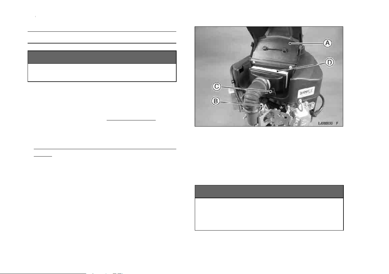
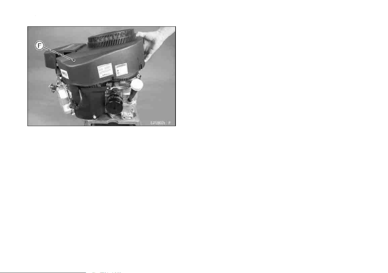
Cooling System Cleaning
Before each use, che c k that the air inlet (rotary)
screen (inside air inlet guard) is free from grass and
debris and clean if necessary. E
very 100 hour s of
operation, check and clean the cooling fins and in-
side of engine shrouds to remove grass, chaff or dirt
clogging the cooling system and causing overheat-
ing. When cleaning, remove the air cleaner (inside
air cleaner cover), the fuel pump, loosen the bolts
and then, remove the fan housing.
NOTICE
Do not run engine before all cooling system
parts are reinstalled to keep cooling and car-
buretion as intended.
[Bolts Size, Tightening Torque]
Bolts
Size
Length Tightening Torque
C
M6 16 mm
8.8 N·m (0.9 kgf·m, 78 in·lb)
D M6 22 mm
8.8 N·m (0.9 kgf·m, 78 in·lb)
A. Air Inlet Guard
B. Fuel Pump
C. D. Bolt
E. Air Cleaner Cov er
31
30 MAINTENANCE
F. Fan Housing
32
STORAGE 31
STORAGE
Fuel System Drain ing
Engines to be stored over 30 days should be com-
pletely drained of fuel to prevent gum deposits form-
ing on essential carburetor parts, fuel filter and fuel
tank.
WARNING
Gasoline is extremely flammable and can be
explosive under certain conditions.
Drain fuel before storing the equipment for
extended periods.
Drain fuel in a well-ventilated area away from
any source of flame or sparks, including any
appliances with a pilot lamp. Store fuel in an
approved container in safe location.
•
Clean every part of the engine.
Be sure that the engine s witch or switch key is
positioned at “OFF”.
Close the fuel valve and remove the sediment
bowl.
Put a pan under the fuel valve to receive the
drained fuel, and open the fuel valve to drain the
fuel from fuel tank completely.
•
Install the sediment bowl and open the fuel valve.
•
To remove the fuel from the carburetor, run the
engine to use up the fuel in the carburetor.
•
Remove the spark plugs and pour approx. 1 ∼ 2
mL (0.06 ∼ 0.1 cu. in.) of engine oil through the
spark plug holes and then screw the spark plugs
in after turning the engine a few times. Slowly turn
the engine until you feel compression and then
leave it there. This blocks the air inside the cylin-
der and prevents rust inside the engine.
Wipe the body with oily cloth.
Wrap the engine with plastic sheeting and store it
in a dry place.
Change engine oil for next use after period of stor-
age (refer to “Oil Change” section in “MAINTE-
NANCE” chapter).
WARNING
Gasoline is a toxic substance. Dispose of
gasoline properly. Contact your local author-
ities for approved disposal methods.
33
32 STORAGE
A. Spark Plug Hole
34
TROUBLESHOOTING GUIDE 33
TROUBLESHOOTING GUIDE
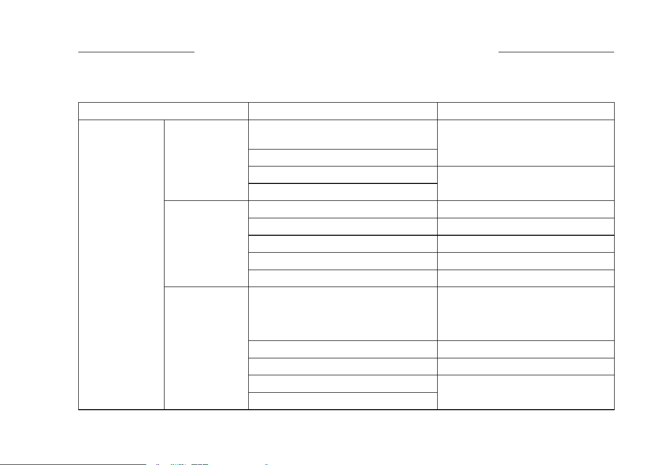
If the engine m alfunctions, carefully examine the symptoms and the operating conditions, and use the table
below as a guide to troubleshooting.
Symptom Probably Cause
Remedy
Faulty pistons, cylinders, piston ri ngs,
and head gaskets
Faulty valves
K
Loose spark plugs
Insufficient
compression
Loose cylinder head bolts
Tighten properly
No fuel in fuel tank Fill fuel tank
Fuel valve not in “ON” position Open fuel valve lever.
Blocked fuel filter or tube Change fuel filter or fuel tube
Blocked air vent in tank cap
Clean fuel tank cap
No fuel to
combustion
chamber
Faulty carburetor K
Over rich fuel/air mixture Open choke.
Rotate engine with spark plugs
removed to discharge excess fuel.
Clean spark plugs.
Clogged air cleaner Clean
Faulty carburetor K
Incorrect grade/type of fuel
Engine won’t
start or output is
low
Spark plugs
fouled by fuel
Water in fuel
Change fuel
35
34 TROUBLESHOOTING GUIDE
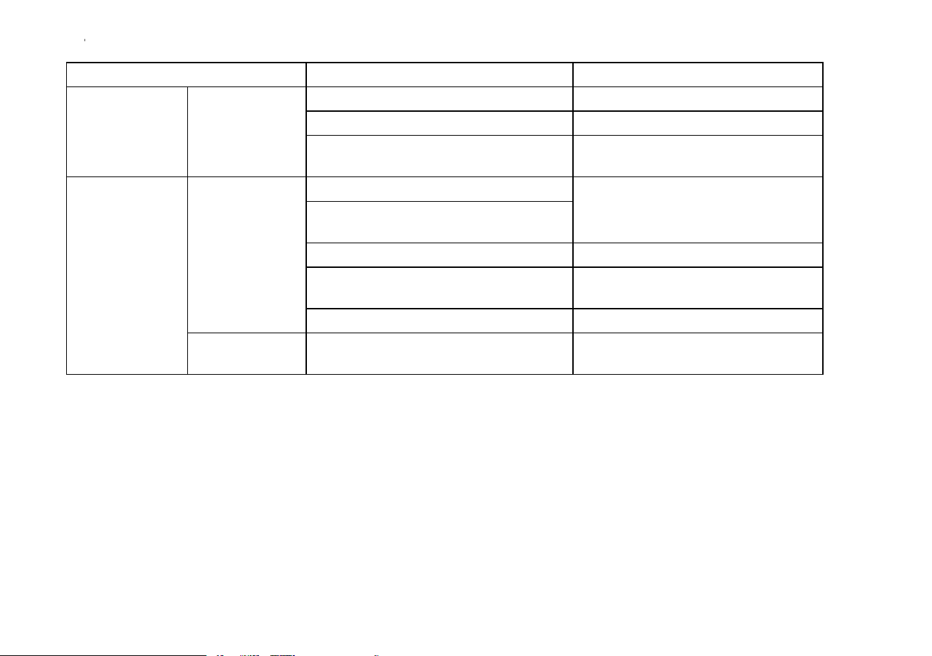
Symptom Probably Cause Remedy
Faulty spark plugs Replace spark plugs
Faulty ignition coil K
No spark or
weak spark
Engine switch left in “OFF” position Turn engine switch to “START”
position (See M)
Clogged air cleaner
Air inlet screen or cooling air path
clogged with dirt
Clean
Insufficient engine oil
Replenish or change oil
Carbon build-up in c ombustion
chamber
K
Engine
overheats
Poor ventilation around engine Select a better location
Low output
Engine speed
won’t increase
Faulty governor K
K: Service to be performed by an authorized Kawasaki dealer.
M: For Control Panel Switch Type, move the throttle lever on the equipment away from its low speed end
to turn the engine switch to “START” position.
36

ENVIRONMENTAL PROTECTION 35
ENVIRONMENTAL PROTECTION
To protect our environment, properly discard used batteries, engine oil, gasoline, coolant, or other compo-
nents that you might dispose of in the future.
Consult your authorized Kawasaki engine dealer or local environmental waste agency for their proper dis-
posal procedure.
37
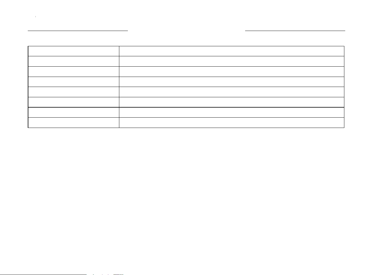
36 SPECIFICATIONS
SPECIFICATIONS
FR541V, FR600V
Type
Air-cooled, 4-stroke vertica l sh aft OHV, gasoline engine
Bore × Stroke 73 × 72 mm (2.88 × 2.84 in.)
Displacement
603 mL (36.8 cu.in)
Ignition Type
Fly wheel magneto fixed timing type
Direction of Rotation Counterclockwise facing the PTO Shaft
Starting System
Electric starter
Dry Weight : kg (lbs) 36.7 (80.9)
NOTE
○
Specifications are subject to change without no-
tice.
○
Dry weight excludes that of fuel tank and muffler.
FR541V, FR600V
Type Air-cooled, 4-stroke vertical shaft OHV, gasoline engine
Bore × Stroke 73 × 72 mm (2.88 × 2.84 in.)
Displacement 603 mL (36.8 cu.in)
Ignition Type Fly wheel magneto xed timing type
Direction of Rotation Counterclockwise facing the PTO Shaft
Starting System Electric starter
CO2 engine emission https://www.kawasaki-engines.eu/en/support/co2-engine-emission-data/
38
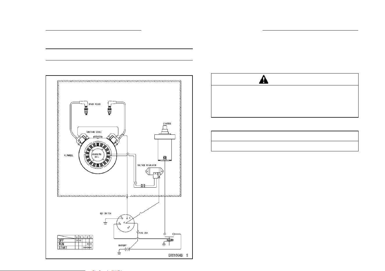
WIRING DIAGRAM 37
WIRING DIAGRAM
Wiring Diagram
[Electric Starter Model]
NOTE
○
Portion Surrounded by hatching Shows Kawasaki
Procurement Parts.
WARNING
Prevent sparks and/or electrical system dam-
age by removing the negative (-) cable from
the battery before attempting any repair or
maintenance.
Battery Capacity Recommended
Battery Capacity
12 V 550 CCA Class
39