
3
29
1
2
(2x)
63
11
(10x)
20
21
(8x)
23
(3x)
16
17
(4x)
11
(9x)
19
(3x)
11
(6x)
13
(2x)
18
15
14
4
12
11
(5x)
5
6
(4x)
11
(2x)
8
(16x)
7
10
9
(8x)
61
1 2 3 11
20 61 63
84
11 19
89
11 18
92
4 5 6 7 8
9 13 14 15
80
11
12
90
16 17
21 23
85
BULLETIN NO.
PN0002528
SERVICE PARTS LIST
CATALOG NO. 2519-20
REVISED BULLETIN
SPECIFY CATALOG NO. AND SERIAL NO. WHEN ORDERING PARTS
M12 FUEL™ High Speed CHAIN SNAKE
SERIAL NO.
DATE
Feb. 2025
WIRING INSTRUCTION
R06A
See Page 5-6
0
00
EXAMPLE:
Component Parts (Small #)
Are Included When Ordering
The Assembly (Large #).
MILWAUKEE TOOL
l
www.milwaukeetool.com
13135 W. LISBON RD., BROOKFIELD, WI 53005
Drwg. 1
FIG. SERVICE NOTES
63
A clean, dry surface is essential for proper performance for
any adhesive system. The area intended for application of any
adhesive label or nameplate must be prepared by cleaning with
isopropyl alcohol. The solvent is to be applied with a clean, lint
free applicator and the surface allowed to dry before applying
the label or nameplate.
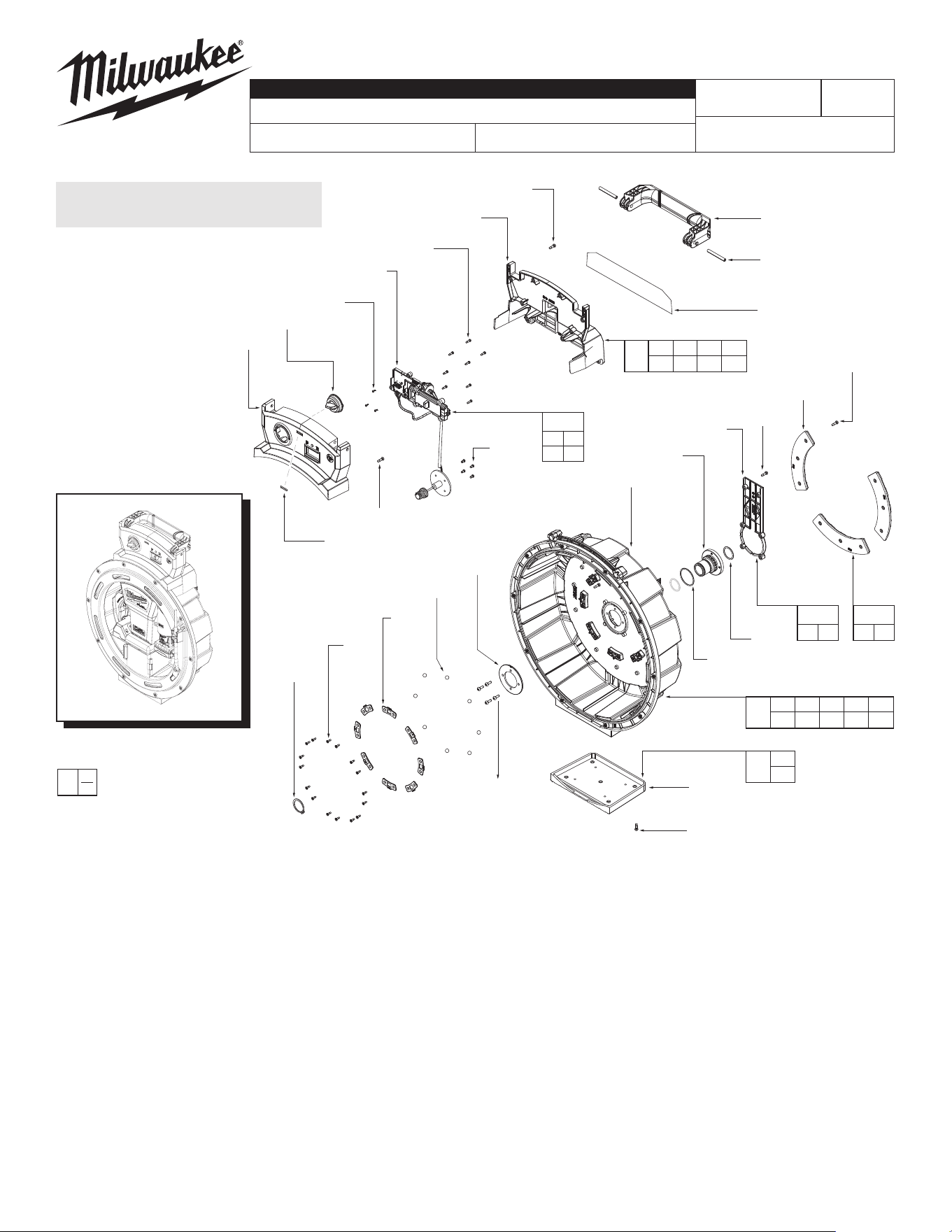
FIG. PART NO. DESCRIPTION OF PART NO. REQ.
1 --------------- Carry Handle (1)
2 --------------- Coil Pin, 2 inch (2)
3 --------------- Handle Support (1)
4 --------------- Stationary Outer Drum (1)
5 --------------- Drum Shaft Support Stamping (1)
6 05-88-1206 M4 x 12mm Pan Hd. T-20 M Screw (4)
7 --------------- Retaining Ring for Drum Shaft (1)
8 05-74-0477
M3 x 10mm Flat Hd. Torx T-10 Screw
(16)
9 --------------- Stamping (8)
10 --------------- 8mm Steel Ball (8)
11 05-88-5375
M4 x 13.5mm Pan Hd. Torx T-20 Screw
(32)
12 --------------- Rubber Pad (1)
13 --------------- O-Ring, Drum Shaft Seal (2)
14 --------------- O-Ring, Drum Shaft Flange (1)
15 --------------- Drum Shaft (1)
16 --------------- PCB for HMI Board (1)
17 06-82-1090 M3.5 x 7mm Pan Hd. T-10 Screw (4)
18 --------------- Slip Ring Cap (1)
19 --------------- Rubber Back Pad (3)
20 --------------- Handle Cover (1)
21 05-81-0005 M3 x 11mm AEG Screw (8)
23 05-88-0106 M2 x 5.5mm Pan Hd T-8 PT Screw (3)
29 43-98-0110 Flex Shaft Speed Knob (1)
61 10-22-1719 Gauge Label (1)
63 12-20-0422 Service Nameplate (1)
80 14-46-0681 Outer Drum Assembly (1)
84 14-46-0686 Handle Kit (1)
85 14-46-0687 UI Board Assembly (1)
89 14-46-0691 Rubber Back Pad Kit (1)
90 14-46-0692 Rubber Foot Pad Kit (1)
92 14-46-0694 Cap for BG Side Kit (1)
100 45-22-0082 39ft Cable Sheath
for 2519-20 (not shown)
(1)
FIG. PART NO. DESCRIPTION OF PART NO. REQ.
HANDLE, UI BOARD ASSEMBLY
& OUTER DRUM ASSEMBLY
Inner Drum, Upper Drum, Drivetrain
Foot Pedal - see page 2
31
35
30
(5x)
59
58
56
11
(6x)
51
60
(6x)
50
43
11
(8x)
46
45
44
30
(10x)
32
(2x)
33
(2x)
34
41
96
62
36
39
11
(4x)
42
37
37c
21
(8x)
37b
37a
37e
37d
40
30 56
58 59
93
30 31
35
83
11 43
45 46
62
81
32 33
34
95
48
47
47 48
88
50 51
60
87
11 40
41 42
91
11 36
86
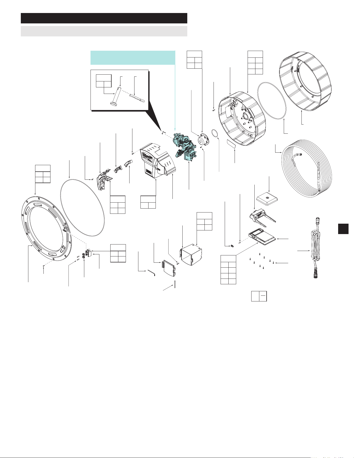
Gearbox, PCBA & Motor System
See Page 3
21 37
37a 37b
37c 37d
37e
94
FIG. PART NO. DESCRIPTION OF PART NO. REQ.
11 05-88-5375
M4 x 13.5mm Pan Hd. Torx T-20 Screw
(18)
21 05-81-0005 M3 x 11mm AEG Screw (8)
30 05-84-0005 M3 x 8mm Cap Hd Hexagon M Screw (15)
31 --------------- Upper Drum Cover (1)
32 05-81-5383 M3.5 x 14mm PH Torx T-10 B Screw (2)
33 --------------- Cable Clip - Urinal (2)
34 --------------- Cable Clip Housing (1)
35 --------------- O-Ring, Upper Drum Cover (1)
36 --------------- Drivetrain Cover (1)
37 --------------- Foot Pedal (1)
37a 05-74-0203
M3 x 11mm CH Hexagon Recess Screw
(1)
37b --------------- Micro Switch (1)
37c --------------- Foot Pedal Power Cord (1)
37d --------------- Foot Pedal Outer Cover (1)
37e --------------- Foot Pedal Top Cover (1)
39 49-96-0045 M2.5 Hex Key (1)
40 --------------- Coil Pin, 55mm long (1)
41 --------------- Door for Chain Knocker Storage (1)
42 --------------- Accessory Storage (1)
43 --------------- Inner Rotating Drum (1)
44 48-53-2519 Flexible Shaft (Accessory) (1)
SERVICE BILL OF MATERIAL (BOM) LISTING - Cont'd
EXAMPLE:
Component Parts (Small #)
Are Included When Ordering
The Assembly (Large #).
0
00
2
45 --------------- Outer Rotating Drum (1)
46 --------------- O-Ring in Drum Seal (1)
47 --------------- Snap Pin (1)
48 --------------- Cable Connection Pin (1)
50 --------------- O-Ring, for Slip Ring Cap (1)
51 --------------- Slip Ring Waterproof Cap (1)
56 --------------- Sheath Retainer Support (1)
58 --------------- Sheath Retainer Cover (1)
59 --------------- Cable Sheath Cover (1)
60 06-82-3002 M3 x 10mm PH Torx T-10 ST Screw (6)
62 10-22-6125 Warning Label (1)
81 14-46-0682 Inner Drum Assembly (1)
83 14-46-0684 Upper Drum Cover Kit (1)
86 14-46-0688 Drivetrain Cover Kit (1)
87 14-46-0690 Waterproof Cap Kit (1)
88 14-46-0689 Cable Connection Pin Kit (1)
91 14-46-0693 Storage Assembly (1)
93 14-46-0695 Cable Sheath Cover Kit (1)
94 14-02-0000 Foot Pedal Assembly (1)
95 14-46-0696 Cable Clip Kit (1)
96 --------------- Gearbox, PCBA & Motor System (1)
FIG. PART NO. DESCRIPTION OF PART NO. REQ.
Inner Drum • Upper Drum • Drivetrain • Foot Pedal
52
(4x)
49
54
55
38
11
(6x)
32
(4x)
11 32
38 49
49a
52
54 55
82
49a
(4x)
3
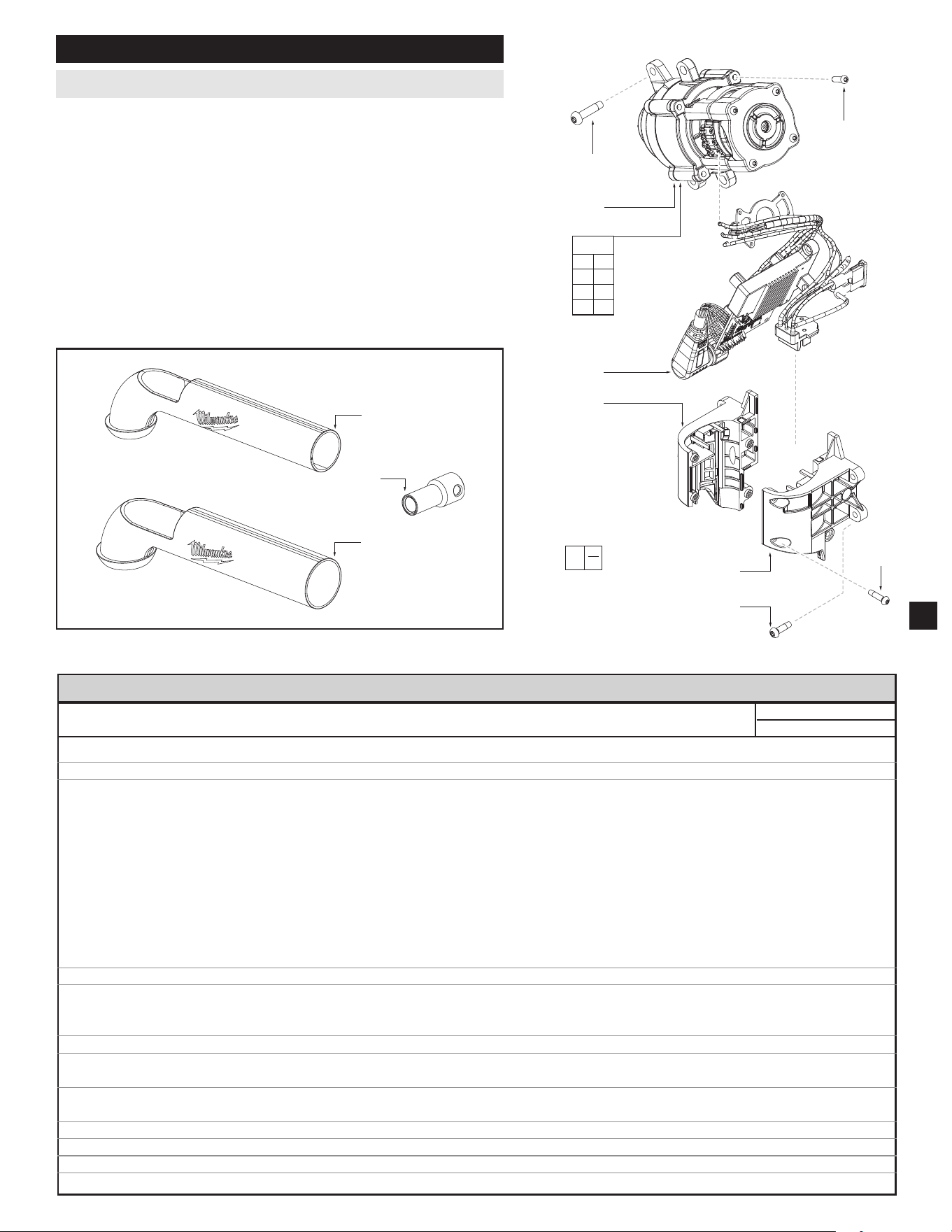
FIG. PART NO. DESCRIPTION OF PART NO. REQ.
11 05-88-5375
M4 x 13.5mm Pan Hd. Torx T-20 Screw
(6)
32 05-81-5383 M3.5 x 14mm Pan Hd. Torx T-10 B Screw (4)
38 --------------- Battery Interface Right Side (1)
49 --------------- Gearbox and Motor System Assy (1)
49a 05-78-1010 M3.5 x 12mm PH Torx T-10 Screw (4)
52 06-82-0152 M5 x 22mm Pan Hd. Torx T-25 Screw (4)
54 --------------- PCBA (1)
55 --------------- Battery Interface Left Side (1)
82 14-46-0683 Gearcase and PCBA Assembly (1)
97 43-56-0056 Cable Connector (1)
98 43-62-0058 1.25" P-Trap Pipe (1)
99 43-62-0059 1.50" P-Trap Pipe (1)
SERVICE BILL OF MATERIAL (BOM) LISTING - Cont'd
Gearcase and PCBA Service Assembly
SEAT TORQUE
FIG. PART NO. DESCRIPTION OF FASTENER QTY WHERE USED (kgf-cm) (lb-in)
6 05-88-1206 M4 x 12mm Pan Hd. T-20 M Screw 4 Drum Shaft Support Washer to Drum Shaft 31 ± 3 26 ± 2.6
8 05-74-0477 M3 x 10mm Flat Hd. Torx T-10 Screw 16 Rotating Ball to Stationary Outer Drum 6 ± 1 5 ± 1
11 05-88-5375 M4 x 13.5mm Pan Hd. Torx T-20 Screw 5 Rubber Pad to Stationary Outer Drum 11 ± 1 10 ± 1
6 BG Side Slip Ring Cap to Stationary Outer Drum 8 ± 1 7 ± 1
9 Rubber Back Pad to Stationary Outer Drum 11 ± 1 10 ± 1
6 Cover Handle to Support Handle 10 ± 1 9 ± 1
4 Cover Handle to Stationary Outer Drum 8 ± 1 7 ± 1
2 Stationary Outer Drum to Support Handle 10 ± 1 9 ± 1
6 Drivetrain Cover to Inner Rotating Drum 8 ± 1 7 ± 1
4 Battery Interface to Inner Rotating Drum 8 ± 1 7 ± 1
4 Accessory Storage to Inner Rotating Drum 8 ± 1 7 ± 1
8 Inner Rotating Drum to Outer Rotating Drum 8 ± 1 7 ± 1
2 Heat Sink to Inner Rotating Drum 10 ± 1 9 ± 1
17 06-82-1090 M3.5 x 7mm Pan Hd. T-10 Screw 4 Slip Ring to Drum Shaft 11 ± 1 10 ± 1
21 05-81-0005 M3 x 11mm AEG Taptite Screw 4 Switch Housing to Support Handle 4 ± 1 3 ± 1
4 UI Housing to Support Handle 4 ± 1 3 ± 1
8 Foot Pedal Base to Top Cover 4 ± 1 3 ± 1
23 05-88-0106 M2 x 5.5mm Pan Hd T-8 PT Screw 3 UI Board to UI Housing 2.5 ± 0.5 2.2 ± 0.4
30 05-84-0005 M3 x 8mm Cap Hd Hexagon M Screw 10 Upper Drum Cover to Stationary Outer Drum 8 ± 1 7 ± 1
5 Cable Sheath Cover to Inner Rotating Drum 8 ± 1 7 ± 1
32 05-81-5383 M3.5 x 14mm PH Torx T-10 B Screw 2 Cable Clip to Upper Drum Cover 14 ± 1 12 ± 1
4 Battery Interface Left Side to Right Side 9 ± 1 8 ± 1
37a 05-74-0203 M3 x 11mm CH Hexagon Recess Screw 1 Micro Switch to Foot Pedal Top Cover 4 ± 1 3 ± 1
49a 05-78-1010 M3.5 x 12mm PH Torx T-10 Screw 4 1st Gearcase to 2nd Gearcase 16 ± 1 14 ± 1
52 06-82-0152 M5 x 22mm Pan Hd. Torx T-25 Screw 4 Gearbox to Inner Rotating Drum 20 ± 1 17 ± 1
60 06-82-3002 M3 x 10mm PH Torx T-10 ST Screw 6 Slip Ring Waterproof Cap to Inner Rotating Drum 3 ± 0.5 2.6 ± 0.4
SCREW TORQUE SPECIFICATIONS
EXAMPLE:
Component Parts
(Small #) Are Included
When Ordering The
Assembly (Large #).
0
00
98
97
99
Additional Serviceable Parts
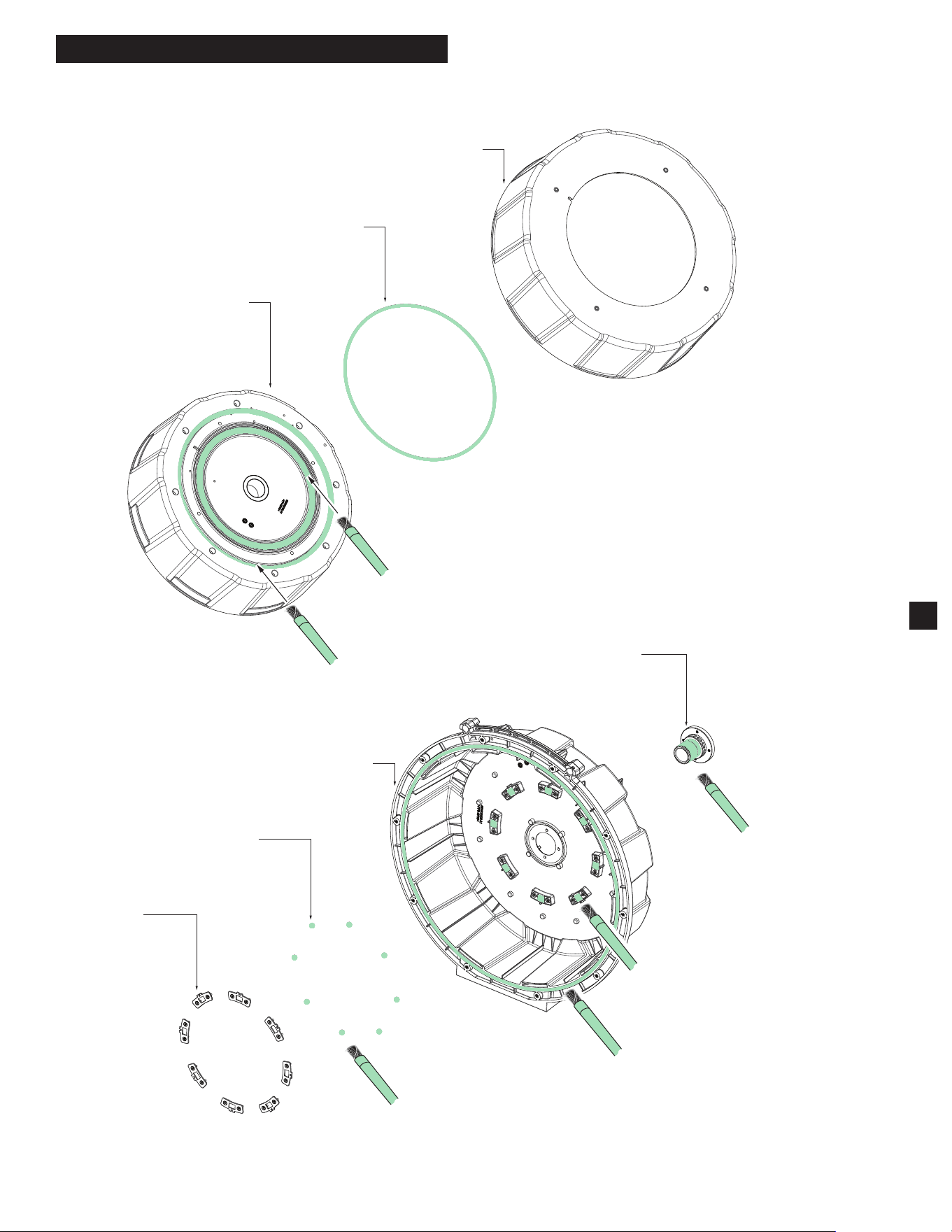
LUBRICATION INSTRUCTIONS
43
46
45
4
9
10
15
Apply about 2G of Grease on the surface
of the Inner Rotating Drum (43)
Apply about 2G of Grease on the surface
while assembling the O-Ring (46)
Mix up the rotating Balls
with about 0.2G of Grease
Apply about 2G of Grease
on the Drum Shaft (15)
Apply 0.3G of Grease on the Ball
grooves in the Stationary Drum (4)
Apply about 1G of Grease on the
groove of the Stationary Drum (4)
►
Type "J" Grease
No. 49-08-4220, 1 lb can
Apply thin coat of grease to areas indicated.
NOTE: When servicing, remove 90-95% of the
existing grease prior to installing Type "J".
Original grease may be similar in color but
not compatible with "J".
4
Fuse
Battery
Interface
Hall Sensor Board
Stator
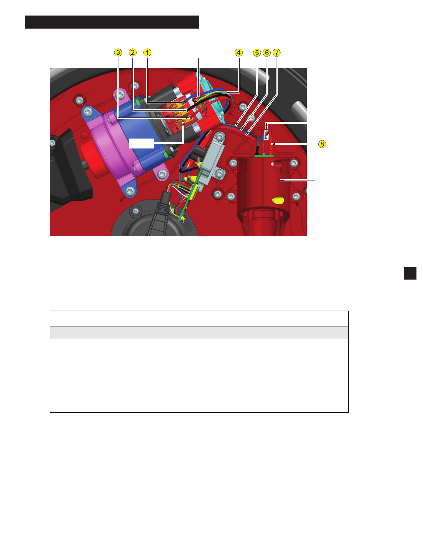
WIRING INSTRUCTIONS
5
Wire Routing Steps:
(1) Put the Fuse into the groove, then lock the Battery Interface.
(2) Put the Terminal Wires (#5, #6, #7) at the bottom of the groove.
(3) Put the Hall Sensor Wire (#4) into the same groove.
(4) Put the Stator Wires (#1, #2, #3) into the top of the groove.
WARNING
• Take notice of wire routing and position in wire guides and traps while dismantling tool.
• Besurethatallcomponentsoftheelectronicskitareseatedrmlyandsquarelyinhousingrecesses.
• Avoid pinched wires, be sure all wires and sleeves are pressed completely down in wire guides and traps.
• Prior to installing housing cover onto handle support, be sure that there are no interferences.
• Be sure to check for C functionality of switches and buttons after housing halves have been secured.
WIRE SPECIFICATION
ITEM WIRE NAME DESTINATION DESIGNATOR WIRE COLOR
1 Stator Wire Control Board ---
>
Stator Blue
2 Stator Wire Control Board ---
>
Stator Black
3 Stator Wire Control Board ---
>
Stator Red
4 Hall Sensor Wire Control Board ---
>
Hall Sensor Board White
5 Terminal Wire Control Board ---
>
Battery Interface Black
6 Terminal Wire Control Board ---
>
Battery Interface Blue
7 Terminal Wire Control Board ---
>
Fuse Red
8 Terminal Wire Fuse ---
>
Battery Interface Red
Wiring continued on next page
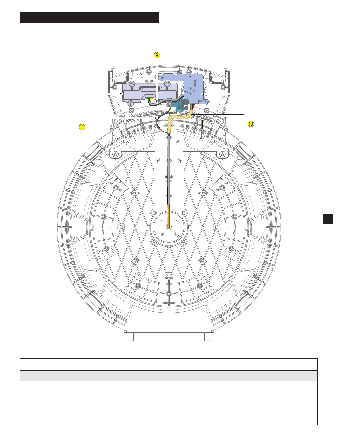
WIRE SPECIFICATION
ITEM WIRE NAME DESTINATION DESIGNATOR WIRE COLOR
9 Switch Wire F/R Switch Board ---
>
UI Board BLACK - Contains 4 smaller wires:
(green, black, red, yellow)
10 Speed Control Wire UI Board ---
>
Slip Ring WHITE - Contains 9 smaller wires:
(
white, purple, brown, tan, green, gray, orange, red, black)
11 Signal Wire Foot Pedal Connector ---
>
Slip Ring BLACK - Contains 2 smaller wires:
(blue, yellow)
6
WIRING INSTRUCTIONS - Continued
F/R Switch Board
Speed Control Board
Foot Pedal Connector Wire
Switch
Wire
Speed Control Wire
Signal Wire