INSTALLATION, USE AND MAINTENANCE INSTRUCTION
GB
SL906 L 1500
SL920 L
TECHNICAL INFORMATION
TYPE: FSLC
COMMERCIAL INFORMATION FOR THE CONSUMER

2

The symbol on the product or on its packaging indicates that this product may not be
treated as household waste. Instead it shall be handed over to the applicable collec-
tion point for the recycling of electrical and electronic equipment. By ensuring this pro-
duct is disposed of correctly, you will help prevent potential negative consequences for
the environment and human health, which could otherwise be caused by inappropriate
waste handling of this product. For more detailed information about recycling of this pro-
duct, please contact your local city ofce, your household waste disposal service or the
shop where you purchased the product. This appliance is marked according to the Eu-
ropean directive 2012/19/EC on waste electrical and electronic equipment (WEEE).
GB
3

CONTENTS
Warnings
Uses
Installation
Working
Maintenance
GB
4

If the rating lable in the cooker-
hood shows the symbol , the
appliance is built in class II°
and it does not need any earth
connection.
If the rating lable in the coo-
ker-hood does not show the
symbol , the appliance is
built in class I° and it needs
the earth connection.
* When performing the electri-
cal connections on the applian-
ce, please make sure that the
current-tap is provided with earth
connection and that voltage va-
lues correspond to those indica-
ted on the label placed inside the
appliance itself.
- Before carrying out any clea-
ning or maintaining operations,
the appliance needs to be remo-
ved from the electric grid. If the
appliance is not provided with a
non-separable exible cable and
plug, or with another device en-
suring omnipolar disconnections
from the grid, with an opening di-
stance between the contacts of
at least 3 mm, then such discon-
necting devices must be sup-
plied within the xed installation.
If the xed appliance is endowed
with a supply cord and a plug,
the appliance has to be put in a
place where the plug can be rea-
ched easily.
WARNINGS
- The bottom of the cooker
hood must be at least at 65 cm
of distance from the hob. It is
recommended to install the co-
oker hood in a central position
above the hob, in order to en-
sure the product’s best perfor-
mance.
* The air sucked can’t be con-
veyed through or into a duct
used to let out fumes from ap-
pliances fed by energy other
than electric power (eg. centra-
lized heating, radiators, water-
heaters, etc.).
- Attention: remove any possi-
ble pvc lm from the stainless
steel.
* To evacuate the air outlet, ple-
ase comply with the pertaining
rules given by competent au-
thorities.
* Provide the room with an ade-
quate aeration when a cooker
hood and appliances fed by ener-
gy other than electric power (gas-,
oil-, or coal- stoves, etc.) are used
simultaneously. The cooker hood,
when evacuating the sucked air,
could generate a negative pres-
sure in the room- which can’t ex-
ceed the limit of 0.04 mbar, in or-
der to avoid the suck of exhausts
deriving from the heat-source.
Therefore the room should be
provided with air-intakes to allow
a costant ow of fresh air.
5

USES
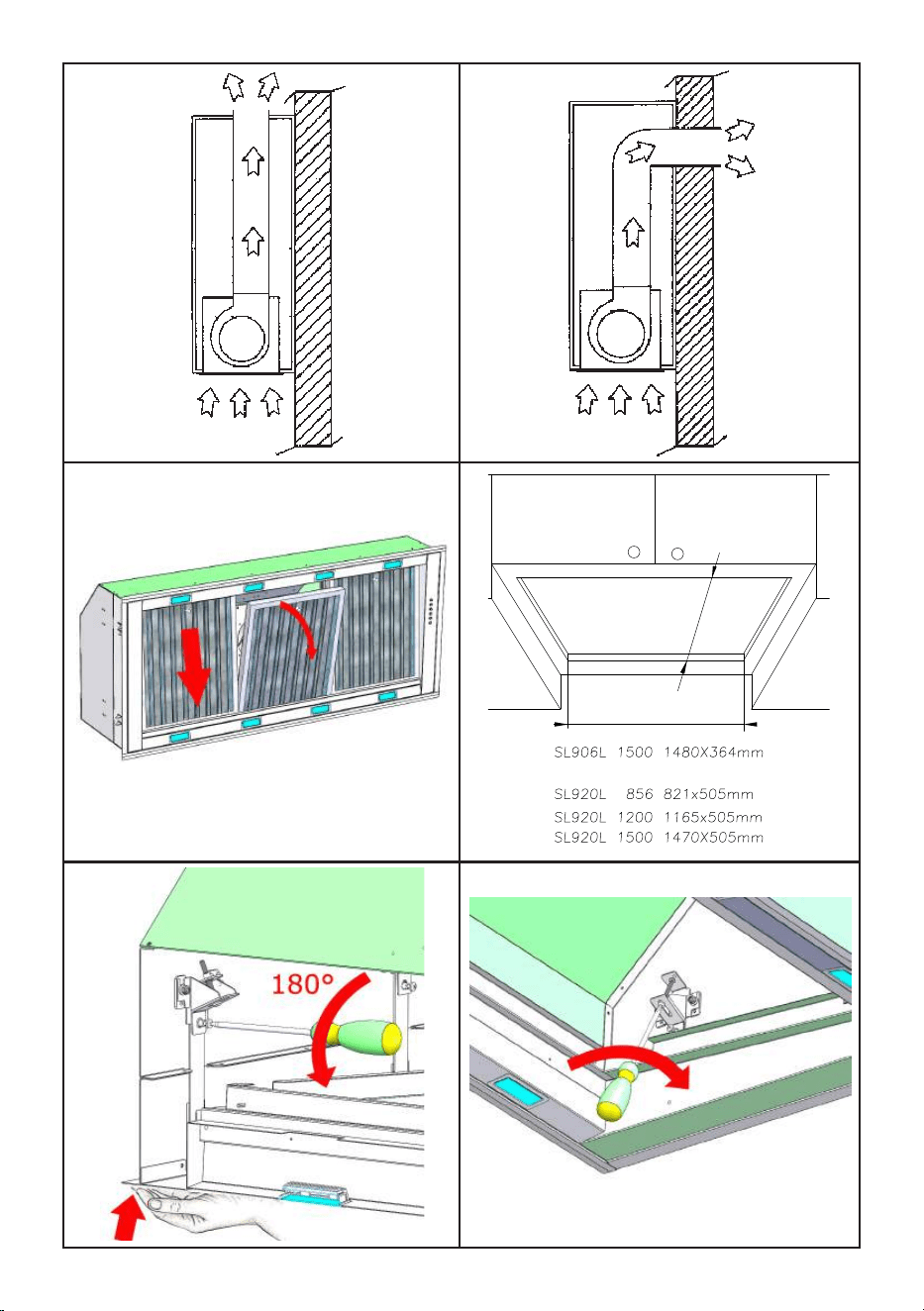
The appliance is already arranged both for lte-
ring and for suction performances.
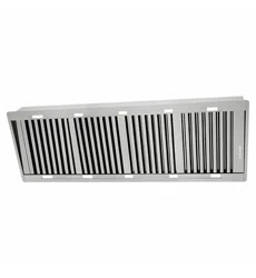
- In its ltering version (Pic. 1), the air and fu-
mes conveyed by the appliance are depured both
by a grease lter and by an active coal lter, and
put again into circulation through the hole made
on the top of the cabinet.
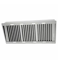
- In its sucking version (Pic. 2), fumes are di-
rectly conveyed outside, through an evacuation
duct connected with the superior part of the wall
or the ceiling. Both coal lter and air deector are
not necessary in this case.
- The use of materials which
can burst into ames should
be avoided in close proximity
of the appliance. When frying,
please pay particular attention
to re risk due to oil grease.
Being highly inammable, fri-
ed oil is especially dangerous.
Do not use uncovered electric
grills. In order to avoid pos-
sible re risk, all instructions
for grease-lter cleaning and
for removing eventual grease
deposits should be strictly fol-
lowed.
To ensure good performances
of the product is recommen-
ded to install the hood central-
ly with respect to the cook top
(Fig. 12).
6

7
INSTALLATION
Before installing the appliance, make sure that
none of the parts is damaged in any way.
In case of damaged parts, contact your retailer
and do not proceed with installation.
Read all of the following instructions with care be-
fore installing the appliance.
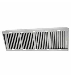
- Before installing the appliance, remove the me-
tal grease lter. This lter can be removed by pu-
shing the handles towards the back side of the
cooker hood and turning it downwards to unfa-
sten it from its slot. (Pic. 3).
To install the appliance please respect the fol-
lowing instructions.
The appliance must be installed by competent
authorities. In order not to damage the electronic
parts of the appliance please do not use additio-
nal screws.
Essential precautions to respect before installing
the appliance are the following:
- Prepare the power supply.
- Prepare a hole for the exhaust of the air both in
the ltering and in the exhausting version.
- Use an exhausting pipe whose maximum length
does not exceed 5 meters.
- Do not use screws to x the outlet pipe to the
cooker hood.
- Limit the no. of elbows in the piping, since each
elbow reduces the aspiration efciency of 1 linear
meter. (Ex.: if you use no. 2 x90 ° elbows, the
length of piping must not exceed 3 meters)
- Avoid abrupt direction changes.
- Use a 200 mm or 300 mm constant diameter
pipe for the whole length.
- Use piping approved by standards in force.
- In the units equipped with 2 motors please use
a 200mm constant diameter pipe for the whole
length.
In the units with 3 motors please use a 300mm
constant diameter pipe for the whole lenght.
Please be sure to have made a cut-out on the
bottom of the cabinet which is suitable to hold the
appliance in position (Fig. 4).
SL906L 1500 1480x364mm
SL920L 856 821X505mm
SL920L 1200 1165X505mm
SL920L 1500 1470X505mm
At this point, insert the range hood inside the
kitchen cabinet until the xed springs will be ho-
oked into.
When the hood will be positioned into the cabinet,
it’s important to x the appliance according to the
following instructions.
Unscrew by 180° the horizontal screws as shown
in g. 5, during this operation it is necessary to
support the hood with your hand (g. 5).
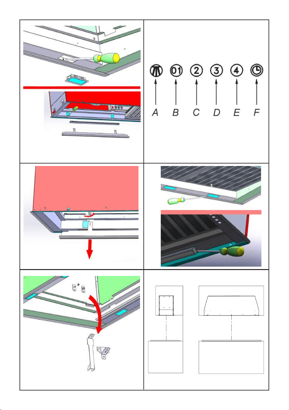
Screw the vertical screws so that the hood is
adherent to the cabinet.
Repeat this operation for all four screws.
If it is necessary, it’s possible to put other screws
along the front or rear of the product as shown in
picture 7.
Warning: according to the model you have pur-
chased, please read the “maintenance” chapter
to check whether the light has to be removed
when installing the screws.
Make the electrical connection and connect the
air outlet pipe.
Warning!
Before connecting the exible exhausting pipe to
the motor, make sure that the stop valve, which is
on the air outlet of the motor, can swing.
Exhausting version
Connect the ange to the exhausting hole with an
appropriate pipe. Connect the appliance with the
electrical mains through the supply cord.
Filtering version
Connect the ange with a pipe suitable to con-
vey the air to the top of the cabinet. Connect the
appliance with the electrical mains through the
supply cord.
8
WORKING
Push button (g. 8)
A: Light switch on/off
B: Motor switch on speed 1/off
C: Motor switch on speed 2
D: Motor switch on speed 3
E: Motor switch on speed 4
F: 10-minutes timer
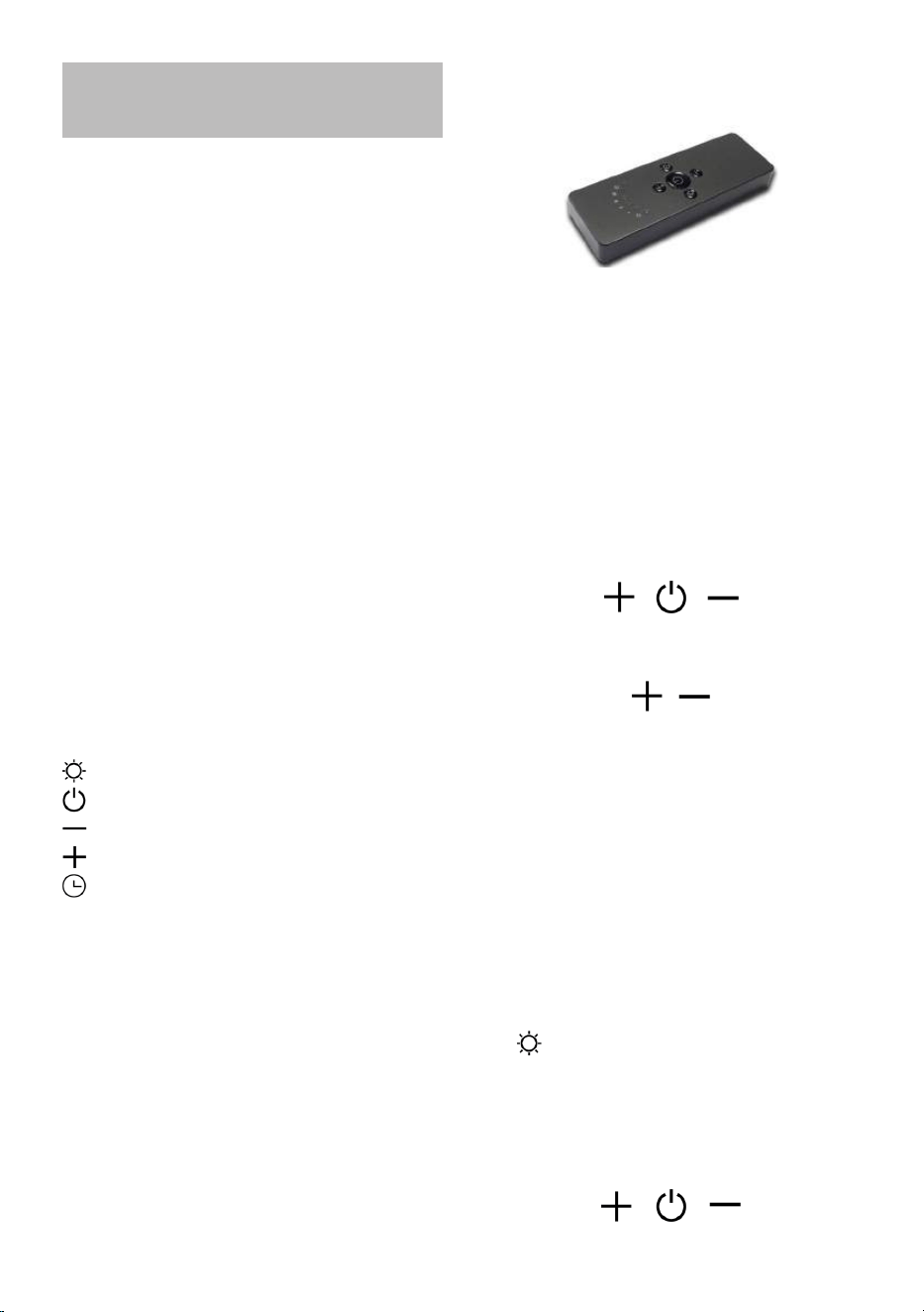
Remote control instruction (If it is included)
RC001
RADIO CONTROL
Radio control used for the remote operation of
ducted cooker hoods.
TECHNICAL DATA
- Alkaline battery powered: 12V mod. 27A
- Operating frequency: 433.92 Mhz
- Combinations: 32.768
- Max. consumption: 25 mA
- Operating temperature: -20 ÷ + 55 °C
- Dimensions: 130x45x15 mm.
OPERATING DESCRIPTION
The transmitter is equipped with 5 buttons for co-
oker hood management, as specied below:
: Light ON/OFF command.
: Motor ON (speed level 1) / OFF command.
: Reduce speed.
: Increase speed.
: 10-minute timer.
INITIAL OPERATING CONDITION
The manufacturer supplies the radio control unit
ready to be used with codes preset in the Factory
OPERATION MODE
Standard conguration:
Standard conguration requires all “cooker hoods
– radio control - system” to be provided with the
same transmission code. In the event two cooker
hoods – radio control system are installed in the
same room or nearby, each system may affect
the operation of the another. Therefore, the code
of one radio control system must be changed.
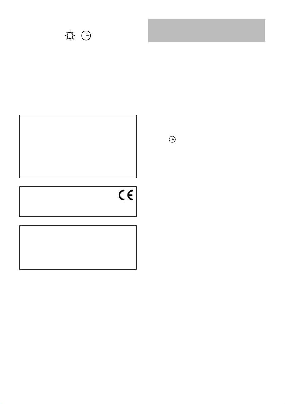
Generating a new transmission code:
The radio control system is provided with preset
codes. Should new codes be required, proceed
as follows: Press simultaneously buttons:
for two seconds. When Leds light on, press but-
tons:
(within 5 seconds). Leds ashing 3 times indicate
the procedure is completed.
WARNING! This operation deletes permanen-
tly the preset codes.
Learning the new transmission code:
Once the transmission code is changed in the ra-
dio control unit, the electronic central unit of the
cooker hood must be made to set the new code
in the fol- lowing way:
Press the main power-off button of the hood and
then restore power to the electronic control unit.
Within the next 15 seconds, press the Liight But-
ton to synchronise the central unit with the
code.
Reset of the Factory conguration:
To restore the Factory conguration, follow the
procedure described below: press simultaneou-
sly buttons:
9
for 2 seconds. When Leds light on, press buttons:
(within 5 seconds). Leds ashing 6 times indicate
the procedure is completed.
WARNING! This operation deletes permanen-
tly the preset codes.
Emergency button:
In the event that the radio control does not work,
use the emergency button to switch the appliance
off. After any necessary repairs have been perfor-
med, reset the emergency button.
WARNING
The battery should be replaced every year to
guarantee the optimal range of the transmitter.
To replace the exhausted battery, take the pla-
stic lid off, remove the battery and replace it
with a new one, observing the correct battery
polarities.
Used batteries should be discarded in special
collection bins.
The below product:
RC001 Radiio Controll
complies with the specications set out in the
R&TTE Directive 99/5/EC.
WARNING
Any adjustments or modications which have
not been expressly approved by the holder of
the legal conformity certicate may invalidate
the user’s rights relating to the operation of
the device.
The products are endowed with an electronic de-
vice which allows the automatic switching off after
4 hours working from the last operation.
- An accurate maintenance guarantees good fun-
ctioning and long-lasting performance.
- Particular care is due to the grease lter. It can
be removed by pushing its special handle toward
the back-side of the cooker hood and turning the
lter downwards so to unfasten it from its slot
(Pic. 3).
To insert the lter just perform the opposite ope-
ration.
After 30 hours working, the push button control
panel will signal the saturation of the grease lter
by lighting all the buttons. Press the timer button
to reset .
The grease lter needs cleaning by regular hand-
washing or in dishwashers every two months at
least or depending on its use.
- How to remove the oil tank.
First, remove the grease lter, Than place your
hand under the oil tank and unfasten the handles
(Pic. 9) Eventually remove the oil tank, paying at-
tention to the leaking oil.
- To clean the appliance itself tepid water and
neutral detergent are recommended, while abra-
sive products should be avoided. For steel ap-
pliances specialized detergents are recommen-
ded (please follow the instructions indicated on
the product itself to obtain the desired results).
* If the supply cord is damaged, it must be re-
placed by the manufacturer or its sevice agent
or a similarly qualied person in order to avoid
a hazard.
Replacing the lamps
Before replacing the lamp switch off the applian-
ce then by using appropriate tools remove the
lamp from its slot (Pic. 10).
Take out the led bar from its connector and repla-
ce with one having similar characteristics.
To nd the correct led bar please check on the
replacement part list.
To remove the appliance from the cabinet is ne-
cessary to remove the installation bracket by the
eight nuts, as shown in the picture 11.
MAINTENANCE
10
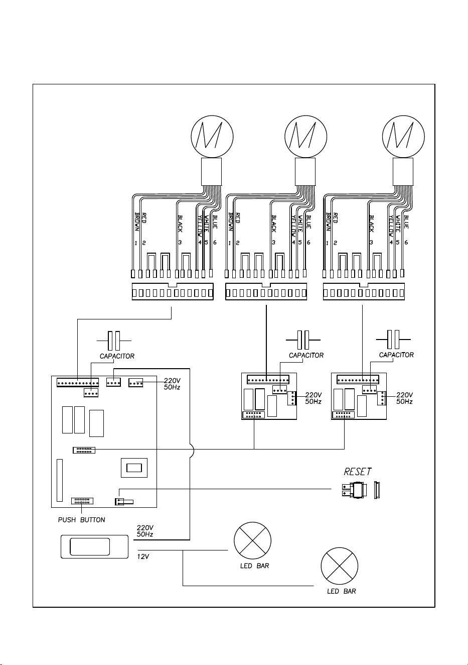
WIRING DIAGRAM SL906L 1500
11
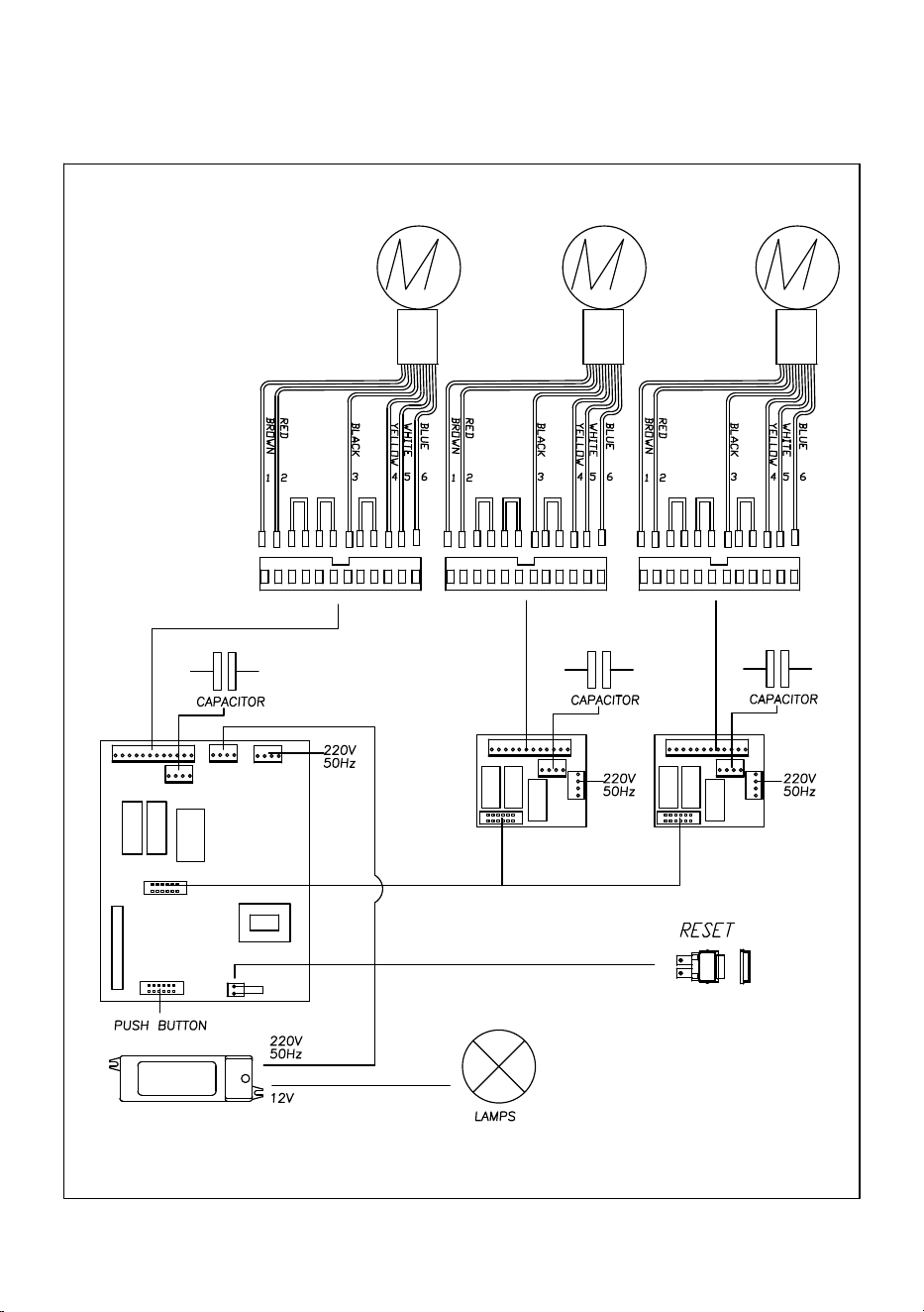
WIRING DIAGRAM SL920
1
12
2
3 4
5
6
7
13
8
10
11
9
12

14

15

90001500906 - 11/17