
1
Owner’s Manual
Purchased product
may differ from image.
B020-U16-19-KG,
B020-U16-19-KF
NetDirector
®
Console KVM Switch
(16-Port)

2
Table of Contents
1. Package Contents 2
2. Features 2
3. System Requirements 3
3.1 Computer 3
3.2 Console 3
3.3 Cables 3
3.4 Operating Systems 3
4. Introduction 4
4.1 Front View of Console KVM Switch 4
4.2 Rear View of Console KVM Switch 5
5. Installation 5
5.1 Pre-Installation Safety Instructions 5
5.2 Rackmounting Instructions for Console KVMs 6
5.3 Grounding 7
5.4 Single-Station Installation 7
5.5 Multiple-Station (Daisy-Chained) Installation 7
5.6 Hot Plugging 8
6. Basic Operation 8
6.1 Opening the NetDirector Console KVM 8
6.2 Closing the NetDirector Console KVM 8
6.3 LCD OSD (On-Screen Display) Conguration 9
6.4 Sharing USB Peripheral Devices 9
6.5 Powering O and Restarting 9
7. Hotkeys 10
7.1 Invoking the Hotkey Mode 10
7.2 Port ID Numbering 10
7.3 Selecting the Active Port 10
7.4 Auto-Scanning 11
7.5 Starting Auto-Scan 11
7.6 Pausing in Auto-Scan 11
7.7 Skip Mode 11
7.8 Hotkey Beeper Control 11
7.9 Computer Keyboard/Mouse Reset 11
7.10 Quick Hotkey Control 12
7.11 OSD Hotkey Comtrol 12
7.12 Port OS Control 12
7.13 Restore Default Values 12
7.14 Hotkey Summary Table 12
8. OSD (On-Screen Display) Operation 13
8.1 OSD Overview 13
8.2 Logging-In for the First Time 13
8.3 OSD Invocation Sequence 13
8.4 OSD Navigation 13
8.5 OSD Main Screen Headings 13
8.6 OSD Functions 14
9. Firmware Upgrade Utility 17
9.1 Before You Begin 17
9.2 Starting the Upgrade 18
9.3 Upgrade Succeeded 18
9.4 Upgrade Failed 18
9.5 Firmware Upgrade Recovery 19
10. Appendix A 19
10.1 Specications 19
10.2 OSD Factory Default Settings 20
10.3 Keyboard Emulation 20
11. Warranty 21
• (1) B020-U16-19-KG or B020-U16-19-KF KVM Switch
• (8) P778-006 USB/PS2 Combo KVM Cable Kits
• (1) USB/PS2 Combo Console Cable Kit
• (1) RJ11 to DB9 Firmware Upgrade Cable
• (1) C13 to C14 Power Cord
• (1) Quick Start Guide
• (1) Grounding Wire
• (1) Rackmount Hardware Kit (Pre-Installed)
Check to see that the unit arrived undamaged and with all of its contents. Contact your dealer if there is a problem.
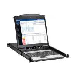
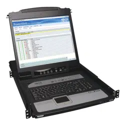
• Integrated KVM console with 19” LCD for the B020-U16-19-KG and B020-U16-19-KF models.
• B020-U16-19-KG and B020-U16-19-KF models include (8) P778-Series USB/PS2 Combo KVM Cable Kits.
• B020-U16-19-KG and B020-U16-19-KF models include an external console port, allowing an external local console (PS/2 or USB) to be
connected. An additional USB port is included on the front panel can be used with an external mouse.
1. Package Contents
2. Features

3
2. Features
3.1 Computer
• A VGA, SVGA or MultiSync computer with an HD15 port
Note: The max resolution is 1280 x 1024. The resolutions of the connected computers must not exceed these limits.
Either:
1. A Mini-DIN 6 (PS/2) keyboard and mouse port.
2. A USB Type-A port.
3.2 Console*
• A VGA, SVGA, or MultiSync monitor capable of the highest resolution on any system in the installation
• A PS/2 or USB-style mouse
• A PS/2 or USB-style keyboard
*Optional external console ports are included on the NetDirector Console KVM Switches.
3.3 Cables
This KVM switch requires the following custom-wired premium cables:
Function Tripp Lite Part
To Connect a PS/2 or USB Computer to the KVM P778-Series PS/2 or USB Combo KVM Cable Kit
Daisy-Chain Cables P772- Series Daisy-Chain Cables
3.4 Operating Systems
OS Version
Windows 2000 and higher
Linux RedHat 7.1 and higher
Linux SuSE 9.0 and higher
Linux Mandriva (Mandrake) 9.0 and higher
UNIX AIX 4.3 and higher
OS Version
UNIX FreeBSD 4.2 and higher
UNIX Sun Solaris 8 and higher
Novell Netware 5.0 and higher
Mac OS 9 and higher
DOS 6.22
3. System Requirements
• Dual Interface supports computers with PS/2 or USB keyboards and mice.
• Keyboard and mouse emulation (PS/2 and USB) allows for simultaneous booting of computers even when the console focus is elsewhere.
• The B020-U16-19-KG uses a German (QWERTZ) keyboard layout and the B20-U16-19-KF uses a French (AZERTY) keyboard layout.
• External USB port allows for sharing of USB1.1 peripherals among all ports on the KVM switch.*
• Multiplatform support: supports Windows, Linux, Mac and Sun.
• Supports multimedia USB keyboards for PC, Mac and Sun.
• Daisy-chain up to 31 additional switches to connect up to 264 computers.
• The B022-U08 can be daisy-chained from the B020-U16-19-KG or B020-U16-19-KF.
• Daisy-chained station position is automatically sensed – no need for manual DIP switch settings.
• Station ID LED indicates the switch’s station position.
• No software required.
• Select a computer via push-buttons, hotkeys or On Screen Display (OSD) menus.
• Auto-scan feature allows for continuous scanning of connected computers.
• Hot Pluggable: add/remove computers without powering down the KVM switch.
• Two-level password security: only authorized Users can view and control the connected computers. (Up to four Users and one Administrator).
• Superior video quality: supports resolutions up to 1280 x 1024.
• Rackmountable in 19” rack system (1U).
• Firmware upgradeable.
*USB1.1 peripheral sharing function works only when using the USB Cable Kit connections.
4
4. Introduction
1. Handle
Pull to slide the KVM module out; push to slide the module in
(see item 13 in this table).
2. LCD
After sliding the KVM module out, flip up the cover to access the
LCD monitor.
3. LCD Controls
The LCD On/Off switch is located here, as well as buttons to
control the position and picture settings of the LCD display. See
page10 for details.
4. Station/Port Switches
Press the Port ID up/down buttons to switch to the port
before/after the currently selected port. Press the Station ID
up/down buttons to switch to the station before/after the
currently selected station.
5. LEDs
• Online Port LEDs – There are 8 or 16 LEDs (depending
on the number of ports) at the top of the keyboard panel
that illuminate orange when a computer is connected
and powered-on.
• Port ID LED – A numerical LED displays the number of
the port which currently has the focus of the KVM switch.
• Station ID LED – A numerical LED displays the station
number of the KVM switch that currently has the focus
of the console.
6. Keyboard
7. Touchpad
8. Power LED
Lights BLUE to indicate that the unit is receiving power.
9. Rackmounting Tabs
The rackmounting tabs located at each corner of the unit
secure the chassis to a system rack. Refer to page 7 for
rackmounting details.
10. Lock LEDs
The Num Lock, Caps Lock, Scroll Lock LEDs are located here.
11. Reset Switch
Located to the right of the Lock LEDs. Press this recessed switch
with a thin object to perform a system reset.
12. Firmware Upgrade Section
• Firmware Upgrade Port: The Firmware Upgrade Cable that
transfers the firmware upgrade data from the Administrator’s
computer to the Console KVM Switch plugs in here.
• Firmware Upgrade Switch: During normal operation, this
switch should be in the NORMAL position. (See page18 for
firmware upgrading details.)
13. Slide Release
In order to bring the console out, you must first release it by
sliding these tabs to the inside. See page9 for details on sliding
the console in and out.
14. External Mouse Port
An additional USB port is provided on the front panel of the
keyboard module for an optional external mouse.
15. USB Peripheral Port
A USB 1.1 port is provided for the sharing of USB peripherals
among connected computers (e.g. flash drive, CD-ROM drive, etc).
13
15
11
12
10
9
1
2
3
4
5
8
14
7
6
4.1 Front View of Console KVM Switch
5
4. Introduction
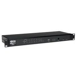
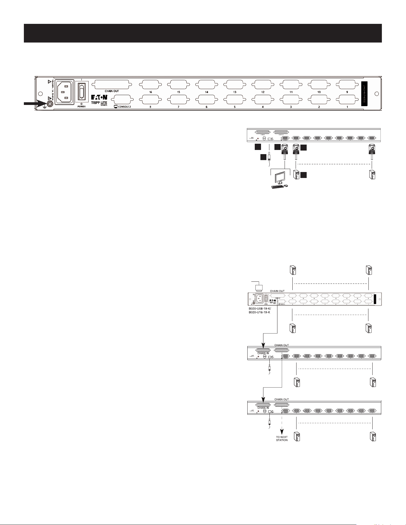
4.2 Rear View of Console KVM Switch
1. Daisy-Chain Port
When daisy-chaining units, the cable plugs in here.
2. CPU Port Section
The cables that link to the computers plug in here.
3. Power Socket
This is a standard 3-prong AC power socket. The power cord from
an AC source plugs in here.
4. Power Switch
This is a standard rocker switch that powers the unit On and Off.
5. External Console Port
This port allows for the optional connection of an external
keyboard, mouse and monitor. The included USB/PS2 Combo
Console Cable Kit connects to the KVM switch here. Either USB or
PS/2 keyboards/mice can be connected.
6. Grounding Terminal
The included grounding wire connects to the KVM switch here.
1
5
2
36 4
5.1 Pre-Installation Safety Instructions
Read all of these instructions and save them for future reference.
General Safety Instructions
• Follow all warnings and instructions marked on the device.
• Do not place the device on any unstable surface (cart, stand, table, etc.). If the device falls, serious damage will result.
• Do not use the device near water.
• Do not place the device near, or over, radiators or heat registers.
• The device cabinet is provided with slots and openings to allow for adequate ventilation. To ensure reliable operation, and to protect
against overheating, these openings must never be blocked or covered.
• The device should never be placed on a soft surface (bed, sofa, rug, etc.) as this will block its ventilation openings. Likewise, the device
should not be placed in a built in enclosure unless adequate ventilation has been provided.
• Never spill liquid of any kind on the device.
• Unplug the device from the wall outlet before cleaning. Do not use liquid or aerosol cleaners. Use a damp cloth for cleaning.
• The device should be operated from the type of power source indicated on the marking label. If you are not sure of the type of power
available, consult your dealer or local power company.
• The device is designed for IT power distribution systems with up to 230V phase-to-phase voltage.
• To prevent damage to your installation it is important that all devices are properly grounded.
• The device is equipped with a 3-wire grounding type plug. This is a safety feature. If you are unable to insert the plug into the outlet, contact
an electrician. Do not attempt to defeat the purpose of the grounding-type plug. Always follow your local/national wiring codes.
• Do not allow anything to rest on the power cord or cables. Route the power cord and cables so that they cannot be stepped on or tripped over.
• If an extension cord is used with this device make sure that the total of the ampere ratings of all products used on this cord does not
exceed the extension cord ampere rating. Make sure that the total of all products plugged into the wall outlet does not exceed 15 amperes.
• To protect against circuit overloading, you should plug your KVM switch and connected computers into a Tripp Lite SmartPro
®
or
SmartOnline
®
UPS System.
• Position system cables and power cables carefully, making sure that nothing rests on any cables.
• Never push objects of any kind into or through cabinet slots. They may touch dangerous voltage points or short out parts resulting in a risk
of re or electrical shock.
• Do not attempt to service the device yourself. Refer all servicing to qualied service personnel.
5. Installation
6
5. Installation
Standard Rack-mounting
1
Slide out the rear mounting brackets from the console and mount both brackets (separate
from the console) to the inside rear of a standard 1U rack system using user-supplied
screws.
2
Take the console and gently slide it into the two rear-mounted brackets in the rack and
secure the console in place by inserting user-supplied screws.
2-Post Rack-mounting
The NetDirector Console KVM Switch can also be mounted in a 2-post rack installation using the
optional 2-Post Rack-mount Kit (model #: B019-000). The mounting hardware allows for the
console to be opened with the drawer in any position. Heavy-duty, 14-gauge steel provides
stability and prevents the console frame from twisting. See the B019-000 instructional manual
for detailed mounting instructions.
• If the following conditions occur, unplug the device from the wall outlet and bring it to qualied service personnel for repair:
o The power cord or plug has become damaged or frayed
o Liquid has been spilled into the device
o The device has been exposed to rain or water
o The device has been dropped, or the cabinet has been damaged
o The device exhibits a distinct change in performance, indicating a need for service
o The device does not operate normally when the operating instructions are followed
• Only adjust those controls that are covered in the operating instructions. Improper adjustment of other controls may result in damage that
will require extensive work by a qualied technician to repair.
• Do not connect the RJ-11 connector marked “UPGRADE” to a public telecommunication network.
• Use of this equipment in life support applications where failure of this equipment can reasonably be expected to cause the failure of the life
support equipment or to signicantly aect its safety or eectiveness is not recommended. Do not use this equipment in the presence of a
ammable anesthetic mixture with air, oxygen or nitrous oxide.
Rack Mounting Safety Instructions
• Before working on the rack, make sure that the stabilizers are secured to the rack, extended to the oor and that the full weight of the rack
rests on the oor. Install front and side stabilizers on a single rack or front stabilizers for joined multiple racks before working on the rack.
• Always load the rack from the bottom up and load the heaviest item in the rack rst.
• Make sure that the rack is level and stable before extending a device from the rack.
• Use caution when pressing the device rail release latches and sliding a device into or out of a rack; the slide rails can pinch your ngers.
• After a device is inserted into the rack, carefully extend the rail into a locking position, then slide the device into the rack.
• Do not overload the AC supply branch circuit that provides power to the rack.
• The total rack load should not exceed 80 percent of the branch circuit rating.
• Make sure that all equipment used on the rack (including power strips and other electrical connectors) is properly grounded.
• Ensure that proper airow is provided to devices in the rack.
• Ensure that the operating ambient temperature of the rack environment does not exceed the maximum ambient temperature specied for
the equipment by the manufacturer.
• Do not step on or stand on any device when servicing other devices in a rack.
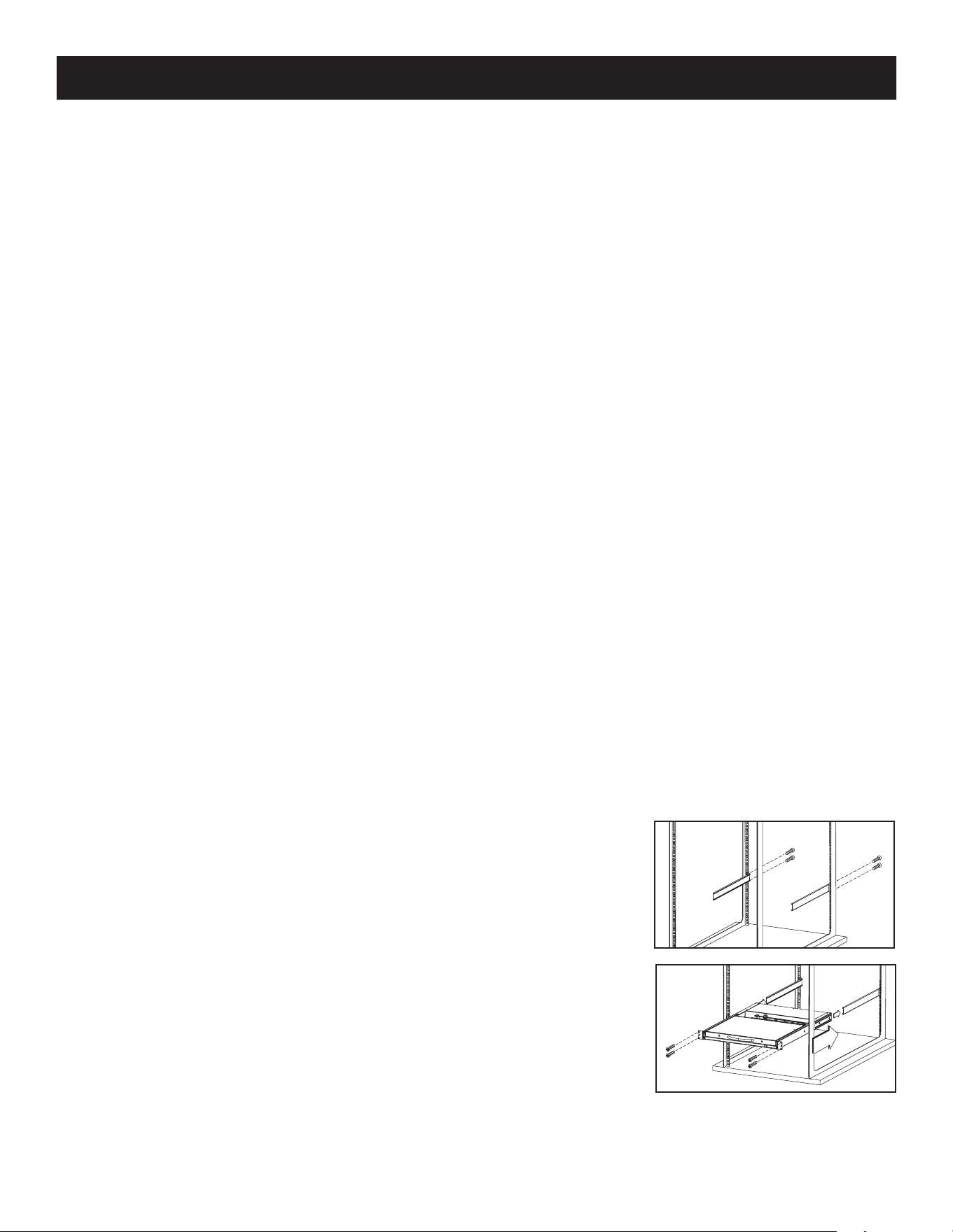
5.2 Rack-Mounting Instructions for Console KVMs
The NetDirector Console KVM Switch is designed for mounting in a 1U rack system. For convenience, a rack-mounting kit is included with your
KVM for quick installation. The mounting options are explained in the sections that follow:
Note:
1. It is recommended that the unit be installed by two people; one to hold it in place and the other to attach it to the rack.
2. The rack-mounting kit that comes with the unit does not include screws or cage nuts. Contact your rack dealer for this hardware.
3. Allow at least 2 inches (5.1 cm) on each side for proper ventilation, and at least 5 inches (12.7 cm) at the rear of the unit for the power cord and cable kits.
11
22
7
5. Installation
2
3
1
5
4
8
08
8
08
8
08
B022-U08
B022-U08
5.3 Grounding
To prevent damage to your installation it is important that all devices are properly grounded. Use the included grounding wire to ground the KVM
switch by connecting one end of the wire to the grounding terminal on the unit and the other end of the wire to a suitably grounded object.
5.4 Single-Station Installation
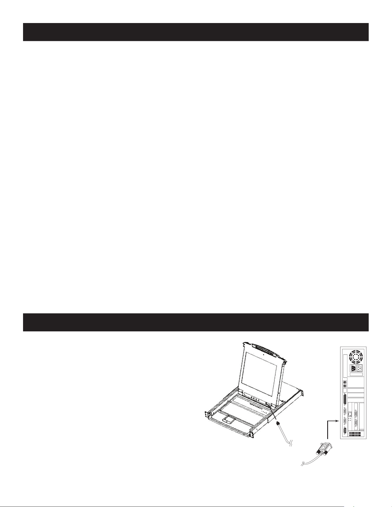
1. Ensure that power to all the connected devices has been turned off.
2. Connect the included USB/PS2 Combo Console Cable Kit to the console
connector on the back of the unit, then connect a monitor, mouse and
keyboard to the appropriate connectors on the cable kit. The distance between
the external console and the KVM switch must not exceed 66 ft. (20 m).
Note: This step is optional for Console KVM Switches.
3. Use a P778-Series USB/PS2 Combo KVM Cable Kit to connect each CPU port to
a computer/server. The distance between the KVM switch and each connected
computer must not exceed 33 ft. (10 m).
4. Plug the power cord or power adapter cable into the KVM’s power jack, then plug into a UPS, surge protector or other AC power source.
Turn on the power switch for the console KVM.
5. Turn on the power to the computers.
5.5 Multiple Station (Daisy-Chained) Installation
To control even more computers, up to 31 B022-U08 KVM Switches can be daisy-chained down from the first station.
Note: As many as 264 computers can be controlled from the unit’s integrated console in a complete installation.
To set up a daisy-chained installation:
1. Ensure that power to all the connected devices has been turned off.
2. Connect the included USB/PS2 Combo Console Cable Kit to the console
connector on the back of the unit, then connect a monitor, mouse and keyboard
to the appropriate connectors on the cable kit. The distance between the
external console and the KVM switch must not exceed 66 ft. (20 m).
3. Use a daisy-chain cable (described in the Cables section) to connect the Chain
Out port of the parent unit to the Chain In port of the child unit. The distance
between any two KVM switches in a daisy-chain must not exceed 49 ft. (15 m).
The distance between the first KVM switch and the last KVM switch in a daisy-
chain must not exceed 328 ft. (100 m), regardless of the number of KVM
switches in the entire chain.
4. Use a KVM cable kit (described in the Cables section) to connect the keyboard,
video and mouse ports of a computer to any available port on the KVM switch.
The distance
between the KVM switch and each connected computer must not
exceed 33 ft. (10 m).
5. Repeat the above steps for any additional KVM switches and computers you
wish to add to the chain.
6. To power up the installation:
a. Plug in the power adapter for the first station. Wait a few seconds to allow the
unit to determine its Station ID.
b. Plug in the power adapters for each subsequent station in the installation (i.e.
second station, third station, etc.). Each KVM switch has an LED display on its
front panel to indicate its Station ID (the Station ID for the first station is 01,
the ID for the second station is 02, the ID for the third station is 03, etc.).
In each case, wait for the Station ID to be displayed on the Station ID LED before
plugging in the next station.
8
5. Installation
5.6 Hot Plugging
All KVM switches support hot plugging—components can be removed and added back into the installation by unplugging their cables from
the ports without having to shut the switch down. However, in order for hot plugging to work properly, these procedures must be followed:
Switching Station Positions
Switch station positions by simply unplugging the daisy-chain cable from the old parent and plugging into a new one. After you do, in order
for the OSD menus to correspond to the change, you must reset the Station IDs via the OSD. See page17 for details.
Hot Plugging CPU Ports
Switch CPU ports by unplugging the KVM cable kit and replugging into the desired port. In order for the OSD menus to correspond to the
change made, you must manually reconfigure the OSD information for the new port. See the F3 SET (page15) and F4 ADM (page16)
functions for details.
Note: If the computer’s Operating System does not support hot plugging, this function may not work properly.
Hot Plugging Console Ports
Keyboard, monitor, and mouse can all be hot plugged. When hot plugging the mouse:
1. You may unplug the mouse and plug it back in again (to reset the mouse, for example), as long as you use the same mouse.
2. If you plug in a different mouse, all the stations and all the computers on the installation must be shut down for 10 seconds then
restarted using the Power Up Sequence described on page8.
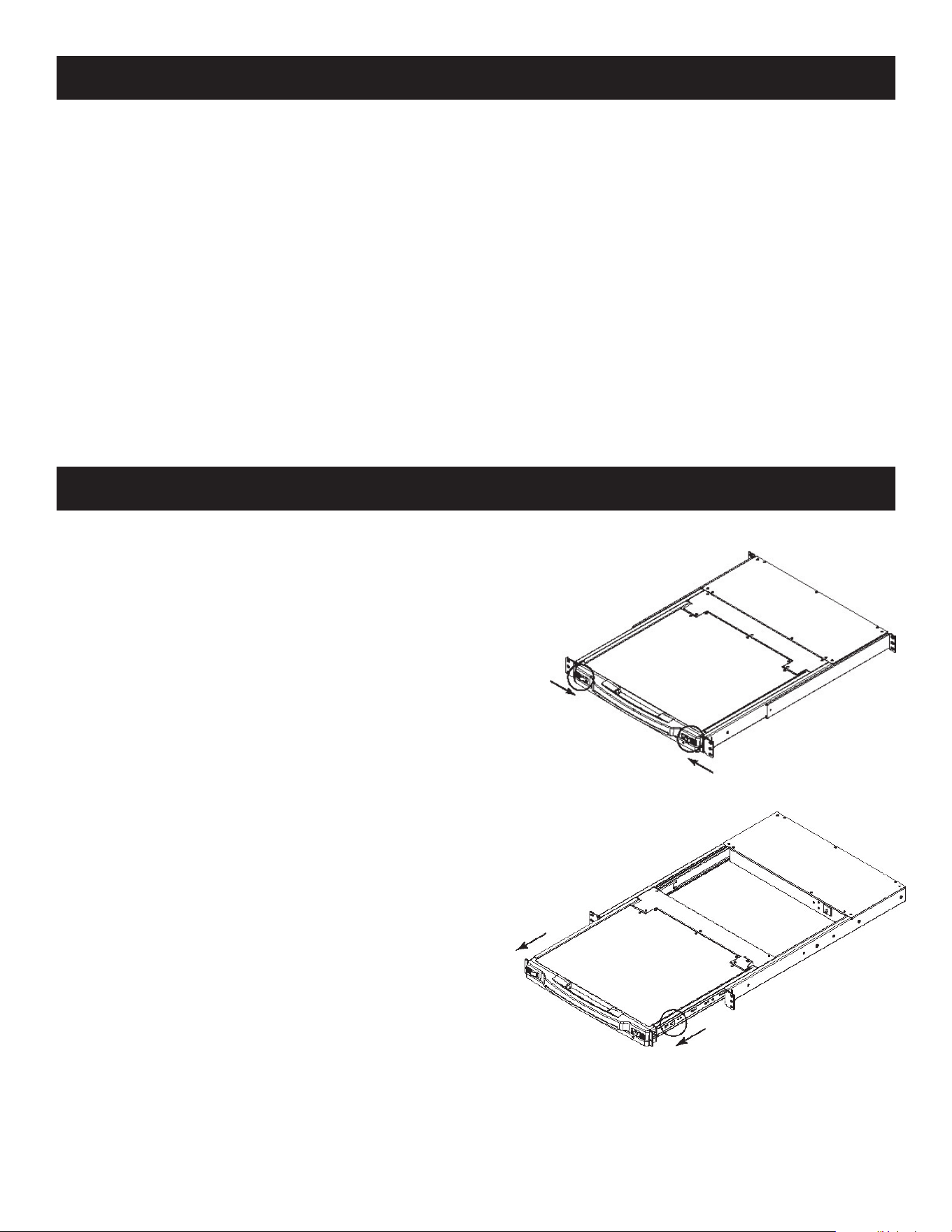
6.1 Opening the NetDirector Console KVM
The console is located under the top cover. To access the console, slide
the console module out and raise the cover.
Note: As a safety precaution, to keep the console from accidentally sliding out, the console
is locked into the “in” position. Before you can pull the console module out, first release it by
pushing the catches on the unit’s front panel toward the center of the switch.
6.2 Closing the NetDirector Console KVM
To slide the console module back in, close the cover and do the
following:
1. Pull the safety catches on the unit’s side rails toward you and push
the module in until it stops.
2. Release the catches; pull the module slightly toward you; then push
it all the way in.
Note: The purpose of the two-step procedure is to minimize the chances of pinching
your fingers when sliding the module in.
6. Basic Operation
9
6. Basic Operation
Exit | | Menu
m m m m
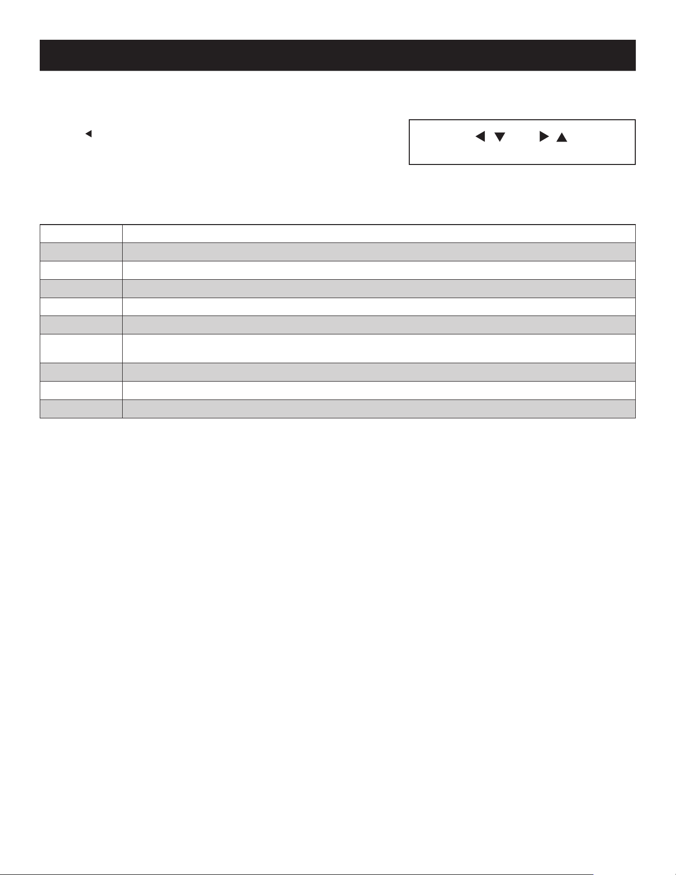
6.3 LCD OSD (On-Screen Display) Configuration
The LCD OSD allows you to set up and congure the LCD:
• To open up the LCD OSD main menu, press the button marked Menu.
• Use the | and | buttons to navigate and make adjustments. After navigating
to a setting choice, use the Menu button to bring up the adjustment screen.
• When making adjustments, | increases the value; | decreases the value.
• When satisfied, press Exit to return to the OSD main menu.
• When all adjustments have been made, press Exit to close the LCD OSD.
The following is an explanation of the settings:
Brightness Adjusts the background black level of the screen image.
Contrast Adjusts the foreground white level of the screen image.
Phase Adjusts the vertical size of the screen image.
Clock Adjusts the horizontal size of the screen image.
H-Position Positions the display area on the LCD panel horizontally (moves the display area left or right).
V-Position Positions the display area on the LCD panel vertically (moves the display area up or down).
Color
Temperature
Adjusts the color quality of the display between three pre-configured settings; 6500k, 7500k, 9300k. This menu also allows you
to customize the individual RGB settings to your preference.
Language Selects the language that the OSD displays its menus in.
OSD Duration Adjust the length of inactivity before the OSD display turns o (between 5 and 100 minutes). The default is 5 minutes.
Reset Resets all of the adjustments in the LCD OSD menus to their factory default settings.
Note: Pressing the Exit button while not in the LCD OSD Menu will perform an auto-configuration on the monitor.
6.4 Sharing USB Peripheral Devices
The USB1.1 port on the Console KVM Switch’s LCD panel can be used to share USB peripherals between connected computers. Simply
connect a USB peripheral device to this port and any connected computer you switch to will have access to the device.
Note: The following limitations apply to the USB peripheral port:
1. This port serves as a single-port USB 1.1 hub; USB 2.0 devices will not function as designed.
2. USB peripherals can only be shared among computers that are connected to the KVM switch via the USB connectors on the P778-Series USB/PS2 Combo KVM Cable Kit.
3. USB peripherals can only be shared among computers that are connected to the KVM switch that the USB peripheral is plugged into. Computers that are connected to daisy-
chained KVM switches will not have access to the USB peripheral device.
6.5 Powering Off and Restarting
If it becomes necessary to power o the KVM switch, follow the procedure below:
1. Shut down all computers connected to the KVM switch. If you are powering off a daisy-chain installation, shut down all computers
connected to each KVM switch in the installation.
Note: It is necessary to unplug any computers that have the Keyboard Power On function. If left on, the KVM switch will continue to receive power via these computers.
2. Turn off the KVM switch (Console KVM only) and unplug the KVM switch from its power source. Power off and unplug each KVM switch
in the daisy-chain in succession.
3. Wait 10 seconds and then plug the KVM switch, starting with the first station, back into its power source. Turn on the power to the KVM
switch (Console KVM only).
4. Once the first station KVM switch has ascertained its position in the daisy-chain, power on and plug in the next KVM switch in the
installation. Follow this procedure for each KVM switch in the installation.
5. Once all KVM switches in the installation have been powered back on, turn on the power to all connected computers.

10
7. Hotkeys
NetDirector KVM Switches can be easily operated using hotkey commands. This chapter discusses the available hotkeys and their functions.
Below is a list of the various hotkeys, broken up into hotkeys for port control and hotkeys that perform other functions.
Port Control Hotkeys
• Selecting the active port
• Auto-Scan Mode port switching
• Skip Mode port switching
Other Hotkeys
• Computer keyboard and mouse reset
• Setting the Beeper
• Setting the Quick Hotkey
• Setting the OSD Hotkey
• Setting the Port Operating System
• Restoring the OSD default values
7.1 Invoking the Hotkey Mode
All hotkey operations begin by invoking Hotkey Mode. In order for Hotkey Mode to work, it must be activated in the KVM’s OSD; it is activated
by default. (See page 16 for details on OSD hotkey activation.) There are two sequences that can be used to invoke Hotkey Mode, both of
which are explained below. You can toggle between these two sequences using the OSD. (See page 15 for details on switching the Hotkey
Mode invocation sequence.) The [Num Lock] and [-] Minus keys are the default invocation keys.
Num Lock and Minus (-) keys
1. Press and hold down the [Num Lock] key.
2. While the [Num Lock] key is held down, press and release the [-] Minus key.
3. After releasing the [-] Minus key, release the [Num Lock] key.
Control and F12 keys
1. Press and hold down the [Ctrl] key.
2. While the [Ctrl] key is held down, press and release the [F12] key.
3. After releasing the [F12] key, release the [Ctrl] key.
When Hotkey Mode has been invoked:
• The monitor goes blank and the hotkey command line is displayed. This is where you will enter in the hotkey commands described in
this chapter.
• The [Caps Lock] and [Scroll Lock] icons will blink in succession.
• Ordinary keystrokes will be suspended until Hotkey Mode is exited. Hotkey Mode is exited by performing a hotkey command or by
pressing the [Esc] or [Spacebar] keys.
7.2 Port ID Numbering
Each CPU port in an installation is assigned a unique Port ID. The Port ID is made up of two parts: a Station Number, and a Port Number:
• The Station Number is a two-digit number that identifies the switch’s position in the daisy chain sequence. This corresponds to the
number displayed on the front panel Station ID LED.
• The Port Number is a two-digit number which identifies the port number that the computer is connected to.
• The Station Number precedes the Port Number.
• Station and Port numbers are always 2 digits, so 1 - 9 becomes 01 - 09. E.g., a computer attached to Port 7 of Station 15 has a Port ID
of 15-07.
7.3 Selecting the Active Port
You can directly access a port by doing the following:
1) Invoke Hotkey Mode.
2) Enter the Port ID.
The Port ID numbers appear on the command line as they are entered. To correct a mistake, use [Backspace] to erase the wrong
number.
3) Press [Enter].
Once [Enter] has been pressed, the KVM switches to the designated computer and you automatically exit the Hotkey Mode.

11
7. Hotkeys
7.4 Auto-Scanning
Auto-Scan allows the connected computers to be monitored automatically without having to manually toggle between ports. When in Au-
to-Scan Mode, the KVM switch switches through each accessible port at xed intervals. Only ports that the currently logged-in User has been
give access to will be scanned. The default interval is 5 seconds. (See page 15 for details on changing the scan interval.)
7.5 Starting Auto-Scan
To start Auto-Scanning:
1) Invoke Hotkey Mode.
2) Key in [A] and hit Enter. You automatically exit Hotkey Mode and enter Auto-Scan Mode.
3) An autoscan can be paused at any time (see below).
4) To exit Auto-Scan Mode, press [Esc] or [Spacebar].
Note: While Auto-Scan Mode is in effect, ordinary keyboard and mouse functions are suspended - only Auto-Scan Mode compliant keystrokes and mouse clicks can be input.
You must exit Auto-Scan Mode in order to regain normal control of the console.
7.6 Pausing in Auto-Scan
While in Auto-Scan Mode, the scan can be paused in order to keep the focus on a particular computer either by pressing P or with a left
click of the mouse. During the time that Auto-Scanning is paused, the command line displays: Auto-Scan: Paused.
In many cases Pausing is more convenient than Exiting the Auto-Scan Mode because when you Resume scanning while in Pause, you
start from where you left off. If you Exited and restarted, scanning would start from the very first computer on the installation.
To resume Auto-Scanning, press any key or left click. Scanning continues from where it left off.
7.7 Skip Mode
This feature allows you to manually sequence between computers in order to monitor them. This manual version of the Auto-Scan Mode lets
you dwell on a particular port for as long as you like. To invoke Previous/Next Switching:
5) Invoke Hotkey Mode.
6) Key in [Arrow] refers to any of the arrow keys on the keyboard. After you press [Arrow], you automatically exit Hotkey Mode and enter
Skip Mode. You can switch ports as follows:
Skips from the current port to the first accessible port previous to it.
Skips from the current port to the next accessible port.
Skips from the current port to the last accessible port of the previous station.
Skips from the current port to the first accessible port of the next station.
7) To exit Skip Mode, press [Esc].
Note: 1. Once Skip Mode has been invoked, until you exit, you can keep on skipping simply by pressing an Arrow key.
2. While Skip Mode is in effect, ordinary keyboard and mouse functions are suspended—only Skip Mode compliant keystrokes can be input. You must exit Skip
Mode in order to regain normal control of the console.
7.8 Hotkey Beeper Control
The Beeper can be turned On/Off via Hotkey or the OSD (see pages14-18 for OSD details).
To toggle the Beeper, key in the following hotkey combination:
8) Invoke Hotkey Mode with the [Num Lock] + [-] combination.
9) Key in [B].
After you press [B], the Beeper toggles On or Off. The command line displays Beeper On or BeeperOff for one second; then the
message disappears and you automatically exit Hotkey Mode.
7.9 Computer Keyboard/Mouse Reset
If the keyboard or mouse ceases to function for a particular port, you can perform a keyboard/mouse reset via the hotkey command below.
This performs the same function as unplugging/replugging the keyboard and mouse on the connected computer. To perform a keyboard/
mouse reset, do the following:
1. Invoke Hotkey Mode.
2. Press the [F5] key.
After pressing the [F5] key, you exit Hotkey Mode and the KVM switch performs a keyboard/mouse reset for the currently selected computer.
(This may take a few seconds to take aect.) If you fail to regain keyboard/mouse control, perform a system reset. (See page 10 for details on
performing a system reset.)

12
7. Hotkeys
7.10 Quick Hotkey Control
The hotkey sequence to invoke Hotkey Mode can be toggled via hotkey command as well as OSD. (See page 15 for changing the Hotkey Mode
invocation sequence via OSD.) To toggle the invocation sequence between [Num Lock, Minus] and [Ctrl, F12], do the following:
1. Invoke Hotkey Mode.
2. Press the [H] key.
After pressing the [H] key, the Hotkey Mode invocation sequence is changed and the text HOTKEY HAS BEEN CHANGED briey appears on
the monitor. Hotkey Mode is then exited and you regain normal operation of the KVM switch.
7.11 OSD Hotkey Control
The hotkey sequence to invoke the OSD can be toggled via hotkey command as well as OSD. (See page 14 for changing the OSD invocation
sequence via OSD.) To toggle the invocation sequence between [Scroll Lock, Scroll Lock] and [Ctrl, Ctrl], do the following:
1. Invoke Hotkey Mode.
2. Press the [T] key.
After pressing the [T] key, the OSD invocation sequence is changed and the text HOTKEY HAS BEEN CHANGED briey appears on the monitor.
Hotkey Mode is then exited and you regain normal operation of the KVM switch.
7.12 Port OS Control
In addition to choosing the Operating System for a connected port via the OSD (see page 17 for details), the Administrator can set the
Operating System via hotkey command. To change a ports Operating System via hotkey, do the following:
1. Invoke Hotkey Mode.
2. Key in [Function], where [Function] represents one of the following:
a. [F1] – Sets the Operating System to Windows.
b. [F2] – Sets the Operating System to Mac.
c. [F3] – Sets the Operating System to Sun.
After pressing one of these keys, the Operating System will be changed for the selected port and you will exit Hotkey Mode.
7.13 Restore Default Values
This Administrator-ONLY hotkey restores the KVM switch to its default values. (See page 17 for details on restoring the KVM default values via
OSD.) To restore the default values via hotkey, do the following:
1. Invoke Hotkey Mode.
2. Press the [R] key.
3. Hit the [Enter] key.
After hitting the [Enter] key, the text RESET TO DEFAULT SETTING is briey displayed and then Hotkey Mode is exited.
7.14 Hotkey Summary Table
Note: All of the hotkey commands in this table require Hotkey Mode to be invoked to function. (See page 11 for details on invoking Hotkey Mode.)
Hotkey Command Function
[Station, ID], [Port ID], [Enter] Switches the focus of the KVM to the computer connected to the Port ID entered
(see page 11 for details on Port ID numbering).
[A], [Enter] or [Q], [Enter] Starts Auto-Scan Mode. When Auto-Scan Mode is in eect, hitting the [P] key or left-clicking pauses the scan.
Pressing any key resumes the scan.
[B] Turns the Beeper sound on/o.
[Esc] or [Spacebar] Exits Hotkey Mode.
[F1] Sets the Operating System of the selected port to Windows (Administrator-only).
[F2] Sets the Operating System of the selected port to Mac (Administrator-only).
[F3] Sets the Operating System of the selected port to Sun (Administrator-only).
[F5] Performs a keyboard/mouse reset for the computer connected to the selected port.
[H] Toggles between the [Num Lock, Minus] and [Ctrl, F12] Hotkey Mode invocation sequences.
[R], [Enter] Restores the KVM switches default values (Administrator-only).
[T] Toggles between the [Scroll Lock, Scroll Lock] and [Ctrl, Ctrl] OSD invocation sequences.
[] Invokes Skip Mode and skips from the current port to the previous accessible port.
[] Invokes Skip Mode and skips from the current port to the next accessible port.
[
] Invokes Skip Mode and skips to the last accessible port on the previous station.
[
] Invokes Skip Mode and skips to the rst accessible port on the next station.
13
8. OSD (On-Screen Display) Operation
8.1 OSD Overview
The On-Screen Display (OSD) is a text-based interface that allows for control and administration of the KVM switch. When logging onto the
KVM switch, the OSD Main Menu is the rst screen you will see after entering your username and password.
8.2 Logging In For the First Time
The KVM switch features two-level security, with one Administrator and four User accounts. If you are an Administrator accessing the KVM
switch for the rst time, leave the Username and password eld blank and hit the [Enter] key twice to access the OSD Main Menu. Once
logged into the KVM switch as Administrator, you will be able to access all OSD features and customize KVM settings. At this point, it is highly
recommended that you change the Administrator Username and password.
8.3 OSD Invocation Sequence
Once logged into the KVM switch, you will need to use one of two sequences to open the OSD Main Menu; [Scroll Lock, Scroll Lock] or
[Ctrl, Ctrl]. The default OSD invocation sequence is [Scroll Lock, Scroll Lock].
Note: When using the [Scroll Lock, Scroll Lock] OSD invocation sequence, you must hold down the [Fn] key, as the [Scroll Lock] key is part of the [Num Lock] key.
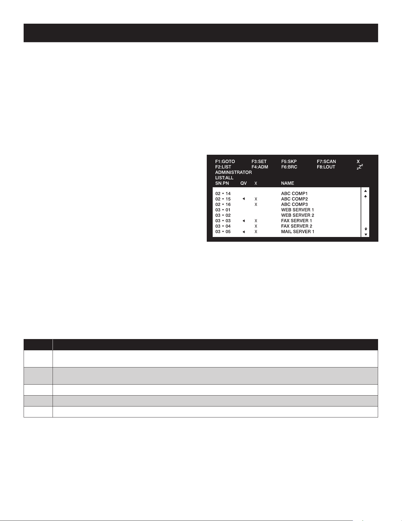
When you invoke the OSD, a screen similar to the one above appears:
Note: 1. The diagram depicts the Administrator’s Main Screen. The User Main Screen
does not have the F4 and F6 functions, since they can’t be accessed by
ordinary Users and are reserved for the Administrator.
2. OSD always starts in List view, with the highlight bar at the same position it
was when it was last closed.
3. Only the ports that have been set accessible by the Administrator for the
currently logged in User are visible (see SET ACCESSIBLE PORTS, page16,
for details).
4. If the port list is collapsed into stations, simply click on the plus sign next to
the desired station number, or highlight the desired station number and hit
the [Enter] key.
8.4 OSD Navigation
• To close the menu and deactivate OSD, click the [X] at the upper right corner of the OSD Window or press [Esc].
• To logout, press [F8], click F8 on the OSD Menu Bar or click the
z
Z
z
symbol at the upper right hand corner of the OSD Screen.
• To move up or down one line at a time, click the Up and Down Triangle symbols (56) or use the Up and Down Arrow Keys.
If there are more entries than appear on the screen, the screen will scroll
• To move up or down one screen at a time, click the Up and Down Arrow symbols (
), or use the [Pg Up] and [Pg Dn] keys.
If there are more entries than appear on the screen, the screen will scroll.
• To activate a port, double-click it or move the Highlight Bar to it, then press [Enter].
• After executing any action, you automatically go back to the menu one level above.
8.5 OSD Main Screen Headings
Heading Explanation
SN The station number of each KVM in the installation will be displayed in this column. The station number of each KVM switch will be
displayed as an expandable folder, which can be expanded to show all of the KVM ports in the station or collapsed to hide them.
PN The port numbers of each KVM in the installation are displayed in this column. If the individual stations are collapsed, their port
numbers will not be displayed.
QV An arrow in this column indicates that the corresponding port is selected for Quick View scanning (see Set Quick View Ports, page17).
A Sun symbol in this column indicates that the corresponding computer is both powered On and On-Line.
NAME If a port has been given a name (see Edit Port Names, page16), its name appears in this column.
14
8. OSD (On-Screen Display) Operation
8.6 OSD Functions
OSD functions allow the KVM to be controlled and congured via the OSD. Using these functions you can quickly jump to a port on the
installation, start an auto-scan, limit the port list that displays when you access the OSD, create/edit port names, etc. To access any of the
OSD functions, simply click on their corresponding function number at the top of the OSD or hit their corresponding function number on the
keyboard. When in the OSD function submenus, simply hit the [Esc] key to exit and return to the previous menu.
F1 Go To (GOTO)
Click the F1 field or press [F1] to activate the GOTO function. GOTO allows you to switch directly to a port either by keying in the port’s Name or its
Port ID.
• To use the Name, enter [1]; key in the port’s Name; then press [Enter]
• To use the Port ID, enter [2]; key in the Port ID; then press [Enter]
Note: A partial Name or Port ID can be entered. The screen will show all the computers that match the Name or Port ID pattern AND that the User is allowed to access.
To return to the OSD Main Menu without making a choice, press [Esc].
F2 List Ports (LIST)
This function lets you tailor the list of ports the OSD will display on the Main Screen. The submenu choices and their meanings are given in the
table below:
Choice Description
ALL Lists all of the ports on the installation that are accessible to the logged-on User.
POWERED ON Lists all of the ports on the installation that are accessible to the logged-on User AND powered-on.
QVIEW This is an Administrator-ONLY option. When selected, it will display only the ports that have been marked as Quick
View ports.
QVIEW + POWERED ON This is an Administrator-ONLY option. When selected, it will display only the ports that have been marked as Quick
View ports AND are powered-on.
Move the Highlight Bar to the desired choice and press [Enter]. An icon appears next to the choice to indicate that it is currently selected.
F3 Set Environment (SET)
This function allows each User and the Administrator to set up their own working environment. A separate profile for each is stored by the OSD
and is activated according to the Username that was provided during login.
To change a setting:
1) Double-click the item; or move the highlight bar to it and press [Enter].
2) After you select an item, a submenu with more choices will appear. To make a selection, either double-click a choice or move the
Highlight Bar to the desired place and press [Enter]. An icon will appear beside the selected choice to identify it. The settings are
explained in the following table:
Setting Function
OSD HOTKEY Select the hotkey that activates the OSD function: use either [Scroll Lock] [Scroll Lock] or [Ctrl] [Ctrl]. Since the [Ctrl]
key combination may conflict with programs running on the computers, the default is the [Scroll Lock] combination.
PORT ID DISPLAY
POSITION
Position the Port ID identifier anywhere on the screen. The default is the upper right corner. Use the Mouse or the Arrow
Keys plus [Pg Up], [Pg Dn], [Home], [End] and [5] (on the numeric keypad with [Num Lock] off) to position the Port ID
display, then double-click or press [Enter] to lock the position and return to the Set submenu.
Note: The position for the ID identifier is set independently for each port on the installation; the choice specified here only applies to the port that
is currently active.
PORT ID DISPLAY
DURATION
This selection gives you the option of displaying the Port ID for 3 seconds, or having the Port ID always o. The default is to
display for 3 seconds.
PORT ID DISPLAY
MODE
Select how the Port ID is displayed: the Port Number alone (PORT NUMBER); the Port Name alone (PORT NAME) or the
Port Number plus the Port Name (PORT NUMBER + PORT NAME). The default is (PORT NUMBER + PORT NAME).
SCAN DURATION Determine how long each port is connected as the KVM cycles through the ports in Auto-Scan Mode (see F7 SCAN
page18). Key in a value from 1 - 255 seconds, then press [Enter]. The default is 5 seconds; a setting of 0 (zero) disables
the Auto-Scan Function.
15
8. OSD (On-Screen Display) Operation
Setting Function
SCAN/SKIP MODE Select which ports will be accessed during Auto-Scan and Skip Modes. Choices are:
• ALL – All accessible ports in the installation will be accessible in Auto-Scan and Skip Modes.
• POWERED ON – All ports that are accessible AND powered on will be accessible in Auto-Scan and Skip Modes.
• QUICK VIEW – This is an Administrator-ONLY option. When selected, only ports that are set as Quick View ports will be
accessible in Auto-Scan and Skip Mode.
• QUICK VIEW + POWERED ON – This is an Administrator-ONLY option. When selected, only ports that are set as Quick
View ports AND powered on will be accessible in Auto-Scan and Skip Mode.
The default setting is ALL.
SCREEN BLANKER If the console is left idle for the amount of time set with this function, the screen is blanked. Key in a value from 1 - 30
minutes, then press [Enter]. A setting of 0 disables this function. The default is 0 (disabled).
HOTKEY COMMAND
MODE
Enables / Disables the hotkey command function if a conflict with programs running on the computers occurs.
HOTKEY Toggle between the two Hotkey Mode invocation sequences. Options are [Num Lock, Minus] and [Ctrl, F12].
OSD LANGUAGE Determines which language the OSD menus are displayed in. Choices are English, Spanish, French, German and Japanese.
TOUCHPAD Enables/Disables the touchpad.
F4 Administrator (ADM)
F4 is an Administrator-ONLY function. It allows the Administrator to configure and control the overall operation of the OSD. To change a setting
double-click it or use the Up / Down Arrow Keys to move the highlight bar to the item and press [Enter].
After an item has been selected, a submenu with additional choices will appear. Either double-click the desired choice, or move the Highlight
Bar to it and press [Enter]. An icon appears beside the selected choice to identify it. The settings are explained in the following table:
Setting Function
SET User LOGIN Sets the Username and password for the Users and the Administrator. One Administrator and four User
accounts are available. To Add/Edit an account, do the following:
• Double-click on the desired account, or highlight it and press the [Enter] key.
• In the screen that appears, enter in (or edit) the desired Username and password for the account. When nished, hit
the [Enter] key to save your changes. Text will appear at the bottom of the OSD stating User SETUP OK, letting you
know your changes have been saved.
Usernames and passwords can be up to 16 characters long, using any combination of letters and numbers (A-Z, 0-9), and
the following characters: Asterisk [*], Parentheses [()], Plus [+], Minus [-], Colon [:], Comma [,], Question Mark [?], Period
[.], Forward Slash [/] and Space. Usernames and passwords are NOT case sensitive. They will always display as uppercase
in the OSD. To delete a character in the Username or password, simply hit the [Backspace] key.
SET ACCESSIBLE PORTS This allows the Administrator to set port access rights for each User. The four User accounts are displayed in columns
at the top of the OSD, and the ports are displayed as rows on the left of the screen. Use the arrow keys to move to the
desired User and port eld, or simply use the touchpad and click on the User and port eld you wish to edit. Press the
[Spacebar] to toggle between three options:
1. F – Full Access.
2. V – View Only Access.
3. [Blank] – No Access.
By default, all Users have Full Access to every port. As the Administrator has access to all ports and settings in the KVM,
you cannot change their access rights.
SET LOGOUT
TIMEOUT
If there is no input from the console for the amount of time set here, the User will be logged out, requiring them to re-
enter their Username and password to regain access to the KVM. This can be set from 0 to 180 minutes, with 0 disabling
the function. Simply type in the desired time frame and hit the [Enter] key to save your change. This is disabled (0) by
default.
EDIT PORT NAMES This function allows the Administrator to give each port a unique name, making it easier to nd the computer you want to
access. To add/edit a port name, do the following:
1. Select the port by double-clicking on it or by highlighting it and hitting the [Enter] key.
2. A name eld will appear at the bottom of the screen. Add or edit the port name and hit the [Enter] key to save the
change. To exit without saving the change, hit the [Esc] key.
Port names can have a maximum of 12 characters, including any combination of letters and numbers (A-Z, 0-9) and the
following characters: Asterisk [*], Parentheses [()], Plus [+], Minus [-], Colon [:], Comma [,], Question Mark [?], Period [.],
Forward Slash [/] and Space. Port names are NOT case sensitive. They will always display as uppercase in the OSD.
RESTORE DEFAULT
VALUES
This allows the Administrator to restore all OSD settings to their factory default values except for the port names and
Username/passwords. When this function is accessed, prompt will appear asking if you wish to restore the default
settings. If yes, type in a Y and hit the [Enter] key. If no, press the [Esc] key to go back to the previous menu.

16
8. OSD (On-Screen Display) Operation
Setting Function
CLEAR THE NAME LIST This function allows the Administrator to clear all of the port names that have been entered. As with the RESTORE
DEFAULT VALUES, you will be prompted upon accessing this function. If you wish to clear the name list, type in a Y and hit
the [Enter] key. If not, press the [Esc] key to go back to the previous menu.
ACTIVATE BEEPER Turns the Beeper sound on or o. Type in Y to turn the Beeper sound on, or N to turn it o. You do not need to hit the
[Enter] key after typing in Y or N, the change will be made automatically.
SET QUICK VIEW PORTS The Administrator can use this function to mark ports as Quick View ports. This gives the Administrator a way to
customize which ports are displayed in the OSD main menu, and which are accessible in Auto-Scan and Skip Modes. To
set ports as Quick View ports, do the following:
1. Highlight the desired port and hit the [Enter] key or click on it using the touchpad.
2. Press the [Spacebar] to toggle Quick View status on/o. An icon will appear in the QV column next to the selected port
when Quick View status is turned on.
Once Quick View ports are set, the Administrator can set up the OSD main page to display only Quick View ports, or only
Quick View ports that are powered on. The Administrator can also set it up so that only Quick View ports, or powered on
Quick View ports, are accessible in Auto-Scan or Skip Modes.
RESET STATION IDS This function is used when you change the position of one of the KVM stations in a daisy-chain. When you change the
position of the station, the OSD does not recognize the change and will not automatically update the main menu to
display the stations in correct order. When this function is used, the KVM will scan the entire installation and update the
station numbers accordingly. The port names of the aected stations will be kept; however, you will need to manually
update all other settings (SET ACCESSIBLE PORTS, SET QUICK VIEW PORTS, etc.).
SET OPERATING
SYSTEM
This allows the Administrator to set the operating system for the port to match that of the connected computer. To set
the operating system, do the following:
1. Highlight the desired port or click on it using the touchpad.
2. Press the [Spacebar] to toggle between four options; WIN, MAC, SUN and OTHER. Each port is set to WIN by default.
3. You do not need to press the [Enter] key to save this setting.
FIRMWARE UPGRADE In order to upgrade the KVMs rmware, Firmware Upgrade Mode must be invoked via this setting. (See page 18 for details
on performing a rmware upgrade.) When you select this option, the rmware version numbers are displayed on the OSD
screen and a prompt will ask if you wish to continue with a rmware upgrade. If yes, type in Y. If no, type in N.
KEYBOARD
LANGUAGE
Sets the language for an external keyboard connected to the KVMs external keyboard port. To select a keyboard
language, double-click on the desired language or highlight it and hit the [Enter] key. You can choose between US
English, UK English, German, Swiss German, French, Hungarian, Italian, Japanese, Korean, Russian, Spanish, Swedish and
Traditional Chinese.
SET CONSOLE MODE This allows the Administrator to set which consoles are enabled for use. Press the spacebar to toggle between three choices:
1. Mode 0 – Both consoles are enabled.
2. Mode 1 – Only the built-in LCD console is enabled.
3. Mode 2 – Only the external console is enabled.
This setting defaults at Mode 0. (Both consoles are enabled.)
F5 Skip (SKP)
Invoke the Skip (SKP) Mode by clicking the F5 field or pressing [F5]. This function skips backward or forward—switching the console focus from
the currently active computer port to the previous or next available one.
• The selection of computers to be available for Skip Mode switching is made with the Scan/Skip Mode setting under the F3 SET function
(see page15).
• When in the Skip Mode, press:
• [] to switch to the previous computer in the list.
• [] to switch to the next computer in the list.
• [] to switch to the last computer on the previous station in the list.
• [
] to switch to the first computer on the next station in the list.
• If a port has been selected for Scan/Skip Mode, a Left/Right Triangle symbol appears before its Port ID Display (when the focus switches
to that port), to indicate so.
• The keyboard and mouse will not function normally in Skip Mode. The only keys you will be able to use are the Arrow keys. The Skip Mode
must be exited in order to regain normal control of the keyboard and mouse.
• To exit Skip Mode, press [Esc] or [Spacebar].
17
8. OSD (On-Screen Display) Operation
F6 Broadcast Mode (BRC)
F6 is an Administrator-ONLY function. Clicking the F6 field, or pressing [F6], invokes Broadcast (BRC) Mode. When this function is in effect,
commands sent from the console are broadcast to all available computers on the installation.
This function is particularly useful for operations that need to be performed on multiple computers, such as performing a system-wide
shutdown, installing or upgrading software, etc.
BRC works in conjunction with the F2 LIST function. The LIST function (see page15) lets you tailor
the list of ports the OSD will display on the
OSD Main Screen. When a command is broadcast, it is done only to the ports currently displayed on the OSD Main Screen.
• A Speaker symbol appears before the Port ID Display to indicate BRC Mode is in effect.
• The mouse will not function while the BRC Mode is in effect. You must exit the BRC Mode in order to regain control of the mouse.
• To exit BRC Mode, invoke the OSD (with the OSD hotkey), then click the F6 field, or press [F6].
F7 Scan (SCAN)
Invoke the Auto-Scan Mode by clicking the F7 field or pressing [F7]. This function allows you to cycle through available computers at regular
intervals so that you can monitor their activity without having to take the trouble of switching yourself.
• The selection of computers to be included for Auto-Scanning is made with the Scan/Skip Mode setting under the F3 SET function (see
page15).
• The amount of time that each port displays for is set with the Scan Duration setting under the F3 SET function (see page15). When you
want to stop at a particular location, press the [Spacebar] or [Esc] to stop scanning.
• If the scanning stops on an empty port, or one where the computer is attached but is powered off, the monitor screen will be blank, and
the mouse and keyboard will have no effect. After the Scan Duration time is up, the Scan function will move on to the next port.
• As each computer is accessed, an S appears in front of the Port ID display to indicate that it is being accessed under Auto-Scan Mode.
• While Auto-Scan Mode is in effect, the keyboard and mouse will not function. You must exit Auto-Scan Mode in order to regain control of
the console.
• While in Auto-Scan Mode, the scanning can be paused in order to keep the focus on a particular computer
either by pressing P, or with a left
click of the mouse.
• To exit Auto-Scan Mode, press the [Spacebar] or [Esc].
F8 Log Out (LOUT)
Clicking the F8 field or pressing [F8] logs you out of the KVM switch and blanks out the Console screen. This is different from simply pressing
[Esc] to deactivate the OSD. With this function you must log in again to regain access to the KVM, whereas with [Esc], you are only logged out
of the OSD screen.
Note: 1. When you reenter the OSD after logging out, the screen stays blank except for the OSD Main Menu. You must input your password before you can continue.
2. If you reenter the OSD after logging out and immediately use [Esc] to deactivate the OSD without having selected a port from the OSD menu, a Null Port message
displays on the screen.The OSD Hotkey will bring up the Main OSD Screen.
9.1 Before You Begin
To prepare for the firmware upgrade, do the following:
1. From a computer that is not part of your KVM installation go to
the support section on Tripplite.Eaton.com and choose the
model name that relates to your device to get a list of available
Firmware Upgrade Packages.
2. Choose the Firmware Upgrade file you want to install (usually the
most recent) and download it to your computer.
3. Use the Firmware Upgrade Cable (provided with this unit), to
connect a COM port on your computer to the Firmware Upgrade
Port of your switch.
Note: When daisy-chaining KVM Switches, a firmware upgrade to station-1 will
upgrade all connected KVMs.
4. Shut down all of the computers.
5. From your KVM switch console, bring up the OSD and select the
F4 ADM function. (See page 16.)
6. Scroll down to FIRMWARE UPGRADE. Press [Enter], then press
[Y] to invoke Firmware Upgrade Mode. For your reference, the
current firmware upgrade version displays on the screen.
9. Firmware Upgrade Utility
18
9. Firmware Upgrade Utility
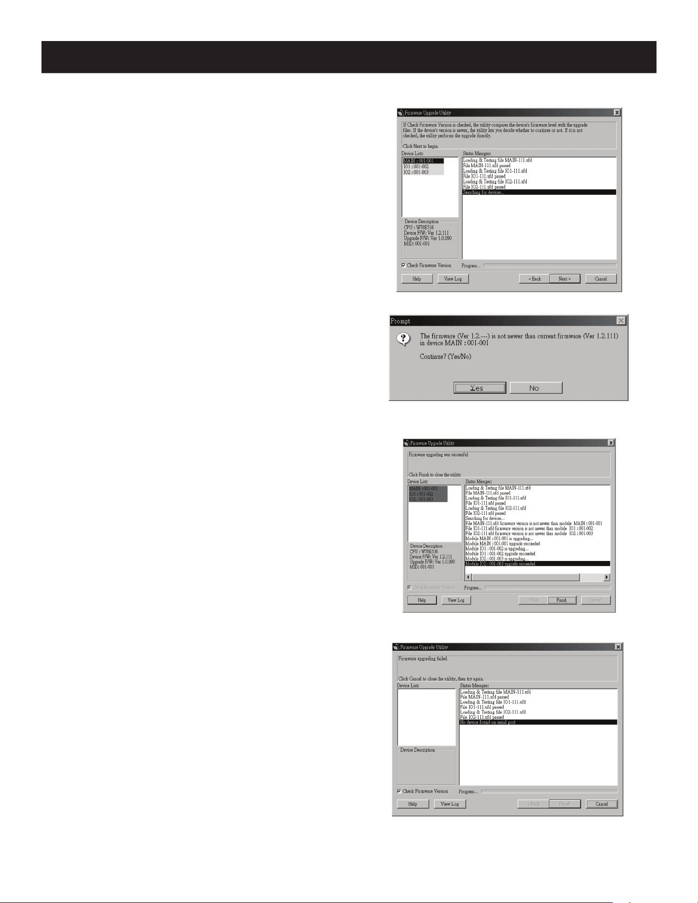
9.2 Starting the Upgrade
To upgrade your firmware:
1. Run the downloaded Firmware Upgrade Utility by double-clicking
the file icon or by opening a command line and entering the full
path to it. The Firmware Upgrade Utility Welcome screen
appears.
2. Read and Agree to the License Agreement (click the I Agree
radio button).
3. Click [Next] to continue. The Firmware Upgrade Utility main
screen appears:
The utility inspects your installation. All the devices capable of
being upgraded by the package are listed in the Device List
panel.
4. As you select devices, a detailed description of each appears in
the Device Description panel.
5. After you have made your selection(s), click [Next] to perform
the upgrade. If you enabled Check Firmware Version, the
utility compares the device’s firmware levels with that of the
upgrade files. If it finds that the device’s version is higher than
the upgrade version, it brings up a dialog box informing you of
the situation and gives you the option to Continue or Cancel.
If the Check Firmware Version is not enabled, the utility
installs the upgrade files without checking whether they are a
higher level version.
As the upgrade proceeds, status messages will appear in the
Status Messages panel and the progress toward completion is
shown on the Progress bar.
9.3 Upgrade Succeeded
After the upgrade has completed, a screen appears to inform you that
the procedure was successful:
Click Finish to close the Firmware Upgrade Utility.
9.4 Upgrade Failed
If the upgrade failed to complete successfully, a dialog box appears
asking if you want to retry. Click Yes to retry. If you click No, the
Upgrade Failed screen appears:
Click Cancel to close the Firmware Upgrade Utility. See the next
section, Firmware Upgrade Recovery, for how to proceed.

19
9. Firmware Upgrade Utility
9.5 Firmware Upgrade Recovery
A firmware upgrade recovery is required in any of the following situations:
• When you invoke Firmware Upgrade Mode (see page18), but decide not to proceed with the upgrade.
• When the main board firmware upgrade fails.
• When the I/O firmware upgrade fails.
To perform a firmware upgrade recovery, do the following:
1. Slide the Firmware Upgrade Recovery Switch (see page4) to the Recover position.
2. Power-off and restart the switch according to the instructions below:
• Shut down all the computers that are attached to it.
Note: Unplug the power cord of any computer that has the Keyboard Power On function. Otherwise, the KVM will still receive power from this computer.
• Wait 10 seconds, then plug the KVM switch back in.
• Once the switch is up, the computers can be powered-on.
Note: If you have shut down more than one Station, power up the highest Station first and work your way down to the lowest one.
3. Slide the Firmware Upgrade Recovery Switch back to the Normal position.
4. Upgrade your firmware using the steps from pages 18-19.
10.1 Specifications
Specification B020-U16-19-KG B020-U16-19-KF
Keyboard Type German Keyboard French Keyboard
Port Selection Methods Push-button, Hotkey, OSD
CPU Ports (x16) HD18 Female
External Console Port(s) HD18 Male
External Mouse Port(s) USB A Female N/A
Daisy-Chain Port DB25 Male
Max Connections via Daisy-Chain 264
Firmware Upgrade Port RJ11 Female
Power Outlet IEC-320-C14
Shared Peripheral Port(s) USB1.1 A Female
Required KVM Cable Kits P778-Series USB/PS2 Combo KVM Cable Kits
Included Cable Kits (x8) P778-006 6ft KVM Cable Kits
Online LEDs (x16) Orange
Selected LEDs N/A
Port LED Numerical LED (Orange)
Station LED Numerical LED (Orange)
Power LED Blue
Keyboard Layout German (QWERTZ) French (AZERTY)
Keyboard/Mouse Emulation USB and PS/2
Max Video Resolution 1280 x 1024 @ 75Hz, DDC2B
Auto-Scan Interval User-Definable (1 to 255 seconds)
I/P Rating 100-240VAC, 50/60Hz, 1A
Power Consumption 120V, 28.5W / 230V, 29.1W
Operating Temperature 32° to 122°F (0° to 50°C)
Storage Temperature -4° to 140°F (-20° to 60°C)
Humidity 0 to 80% RH, Noncondensing
Weight 31.3 lb. (14.2 kg)
Dimensions [H x W x D] 1.75 x 17 x 27 in. (45 x 432 x 686 mm)
10. Appendix A
20
10. Appendix A
10.2 OSD Factory Default Settings
The factory default settings are as follows:
Setting Default
OSD Hotkey [Scroll Lock] [Scroll Lock]*
Port ID Display Position Upper Left Corner
Port ID Display Duration 3 Seconds
Port ID Display Mode The Port Number plus the Port Name
Scan Duration 5 Seconds
Scan/Skip Mode All
Screen Blanker 0 (Disabled)
Logout Timeout 0 (Disabled)
Accessible Ports F (Full) for all users on all ports
Beeper Y (Activated)
*Use of the [Scroll Lock] key requires the [Fn] key to be held down.
10.3 Keyboard Emulation
Mac Keyboard
The PC- compatible (101/104 key) keyboard can emulate the functions of the
Mac keyboard. The emulation mappings are listed in the table below.
Note: When using key combinations, press and release the first key (Ctrl),
then press and release the activation key.
PC Keyboard Mac Keyboard
[Shift] Shift
[Ctrl] Ctrl
[Ctrl] [1]
[Ctrl] [2]
[Ctrl] [3]
[Ctrl] [4]
[Alt] Alt
[Print Screen] F13
[Scroll Lock] F14
=
[Enter] Return
[Backspace] Delete
[Insert] Help
[Ctrl]
F15
Sun Keyboard
The PC- compatible (101/104 key) keyboard can emulate the functions of the
Sun keyboard when the Control key [Ctrl] is used in conjunction with other
keys. The corresponding functions are shown in the table below.
Note: When using key combinations, press and release the first key (Ctrl),
then press and release the activation key.
PC Keyboard Sun Keyboard
potS]T[ ]lrtC[
niagA]2F[ ]lrtC[
sporP]3F[ ]lrtC[
odnU]4F[ ]lrtC[
tnorF]5F[ ]lrtC[
ypoC]6F[ ]lrtC[
nepO]7F[ ]lrtC[
etsaP]8F[ ]lrtC[
dniF]9F[ ]lrtC[
tuC]01F[ ]lrtC[
[Ctrl] [1]
[Ctrl] [2]
[Ctrl] [3]
[Ctrl] [4]
pleH]H[ ]lrtC[
Compose
-
+

21
11. Warranty
3-YEAR LIMITED WARRANTY
We warrant our products to be free from defects in materials and workmanship for a period of three (3) years from the date of initial purchase. Our
obligation under this warranty is limited to repairing or replacing (at its sole option) any such defective products. Visit Tripplite.Eaton.com/support/
product-returns before sending any equipment back for repair. This warranty does not apply to equipment which has been damaged by accident,
negligence or misapplication or has been altered or modied in any way.
EXCEPT AS PROVIDED HEREIN, WE MAKE NO WARRANTIES, EXPRESS OR IMPLIED, INCLUDING WARRANTIES OF MERCHANTABILITY AND FITNESS FOR
A PARTICULAR PURPOSE. Some states do not permit limitation or exclusion of implied warranties; therefore, the aforesaid limitation(s) or exclusion(s)
may not apply to the purchaser.
EXCEPT AS PROVIDED ABOVE, IN NO EVENT WILL WE BE LIABLE FOR DIRECT, INDIRECT, SPECIAL, INCIDENTAL OR CONSEQUENTIAL DAMAGES ARISING
OUT OF THE USE OF THIS PRODUCT, EVEN IF ADVISED OF THE POSSIBILITY OF SUCH DAMAGE. Specically, we are not liable for any costs, such as lost
prots or revenue, loss of equipment, loss of use of equipment, loss of software, loss of data, costs of substitutes, claims by third parties, or otherwise.
Regulatory Compliance Identication Numbers
For the purpose of regulatory compliance certications and identication, your product has been assigned a unique series number. The series number
can be found on the product nameplate label, along with all required approval markings and information. When requesting compliance information for
this product, always refer to the series number. The series number should not be confused with the marking name or model number of the product.
WEEE Compliance Information for Customers and Recyclers (European Union)
Under the Waste Electrical and Electronic Equipment (WEEE) Directive and implementing regulations, when customers buy new electrical and
electronic equipment from Eaton, they are entitled to:
• Send old equipment for recycling on a one-for-one, like-for-like basis (this varies depending on the country)
• Send the new equipment back for recycling when this ultimately becomes waste
Use of this equipment in life support applications where failure of this equipment can reasonably be expected to cause the failure of the life support
equipment or to signicantly aect its safety or eectiveness is not recommended.
Eaton has a policy of continuous improvement. Specications are subject to change without notice.
Eaton
1000 Eaton Boulevard
Cleveland, OH 44122
United States
Eaton.com
© 2023 Eaton
All Rights Reserved
Publication No. 23-05-315 / 93-47C8_RevA
October 2023
Eaton is a registered trademark.
All trademarks are property
of their respective owners.