

2
contents
What's in the box 3
Part Names 4
Front Panel 4
Rear Panel 5
Connections 6
Connecting a Preamplifier 7
Connection using an unbalanced
RCA cable 7
Connection using a balanced XLR
cable 8
Connecting external control
equipment 9
Connecting Your Speakers 10
Preparation 10
General connection 10
Connection using a banana plug or
Y spade plug 11
Connecting the Power Cord 12
Playback 13
Basic Operations 14
Power ON/OFF 14
Backlight ON/OFF 14
Switching the Power Meter Range 15
Switching speakers 15
Setting Auto Standby (ASb) 16
Troubleshooting 17
General Specifications 18
North America and Japan models 18
Europe models 18
Asia and Oceania models 18
Common to all destinations 18
License and Trademark 19
3
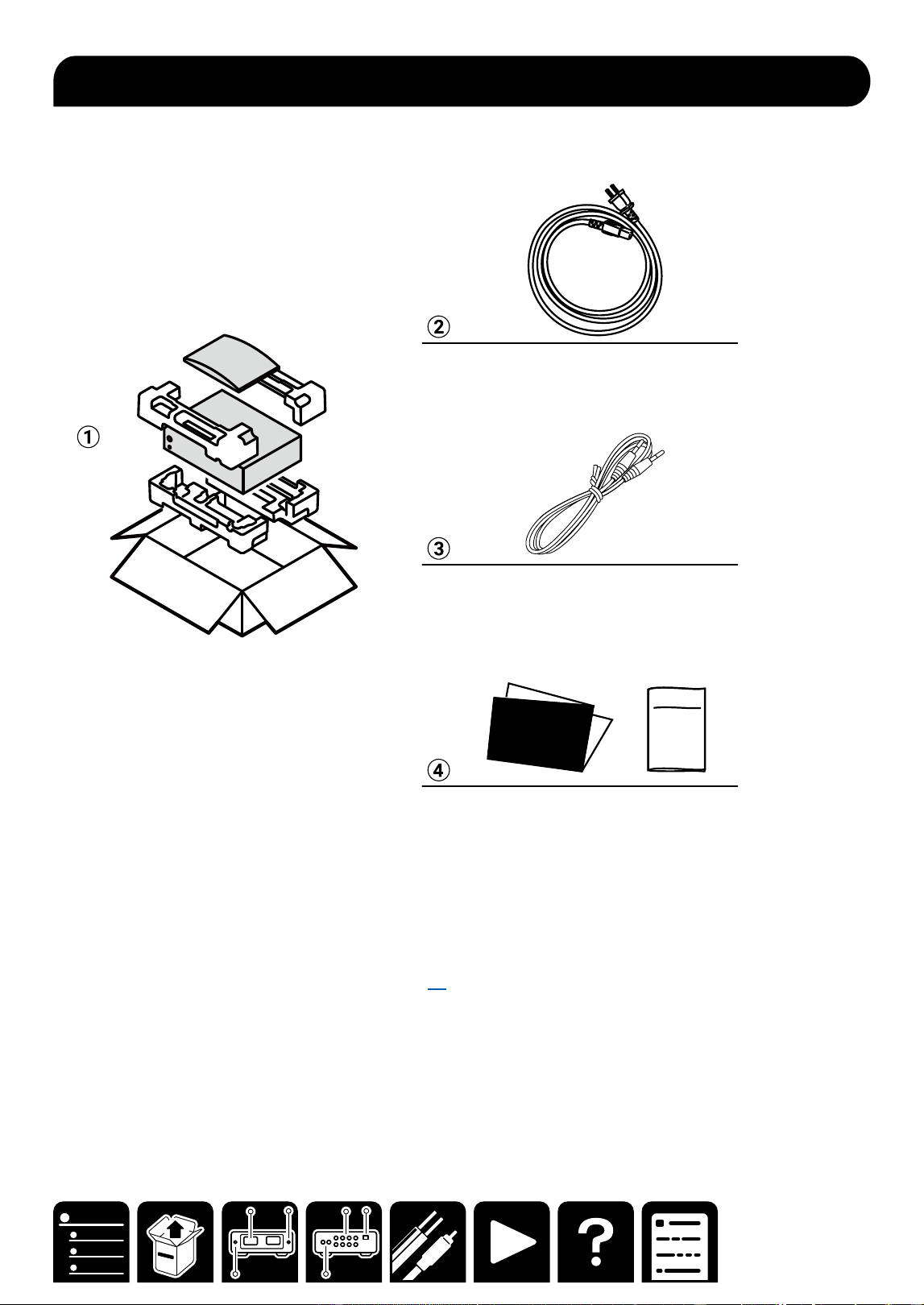
What's in the box
What's in the box
Safety
Information
Initial Setup
Guide
A Main unit
B Power cord (1)
Depending on the model, 2 or more Power Cords are supplied. Use the type of cord suited to your area.
C Mono mini-plug cable (1) (1.8 m/5.9 ft)
This is used to connect the 12V trigger jacks. ( →p9)
D Initial Setup Guide, Safety Information
* This is an online user manual. This is not supplied with the product.
4
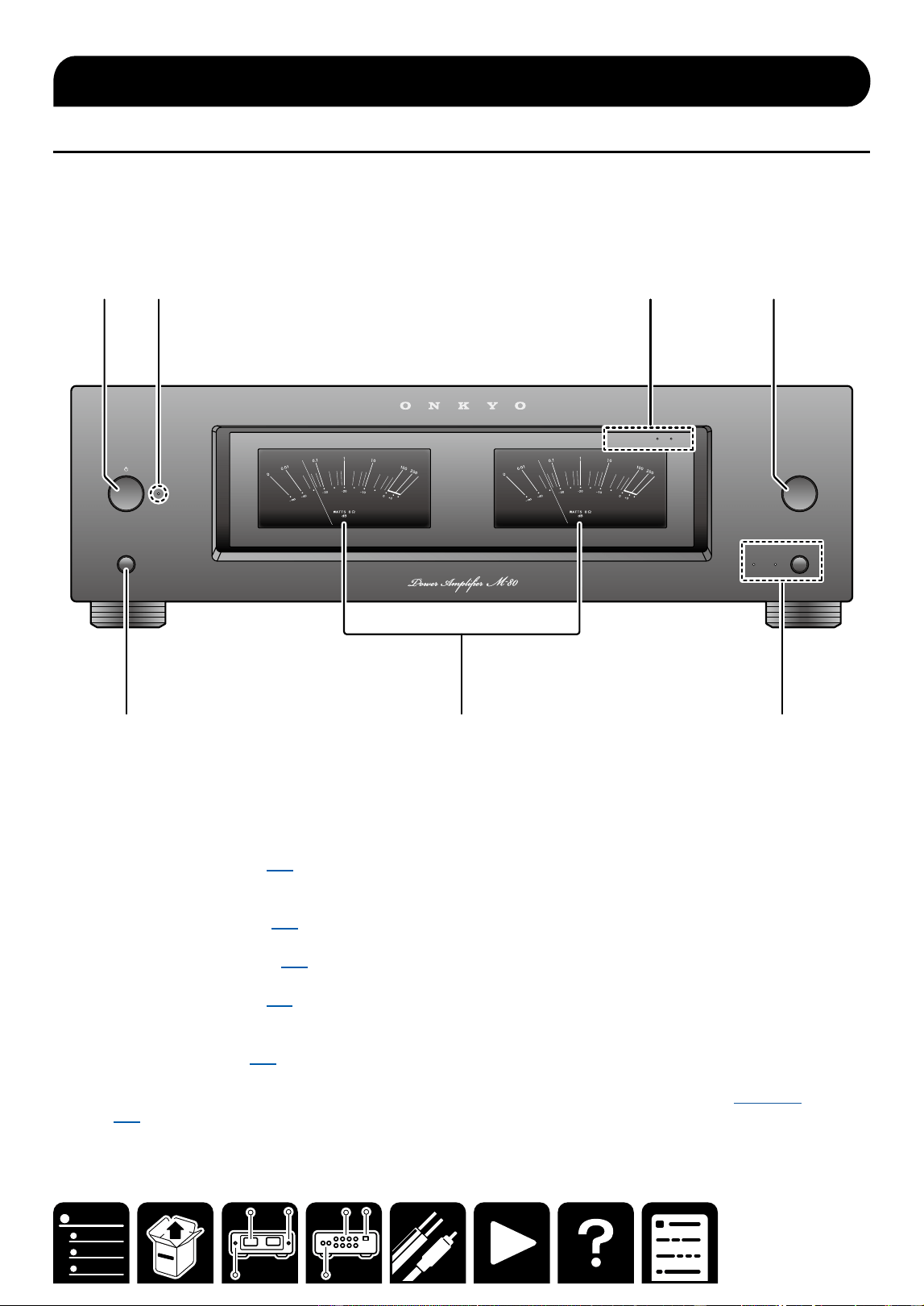
Front Panel
Part Names
Front Panel
BACKLIGHTS
SPEAKERS
BA
METER RANGE
METER RANGE
x
1
x
10
A 2 3 4
5 6 7
A ON/STANDBY button ( →p14)
This button is used to set the power amplifier to On or Standby.
B Power indicator
C METER RANGE LEDs ( →p15)
x1 or x10 lights when the power meter range is x1 or x10.
D METER RANGE button ( →p15)
This button is used to switch the power meter range.
E BACKLIGHTS button ( →p14)
F Power meter
The power meter shows the output power level.
G SPEAKERS button ( →p15)
SPEAKER A/B indicator: Select the terminals to output audio from between SPEAKERS A/B.
・ Depending on this setting, the impedance of a connectable speaker changes. For details, see here
( →p15).
Part Names
5
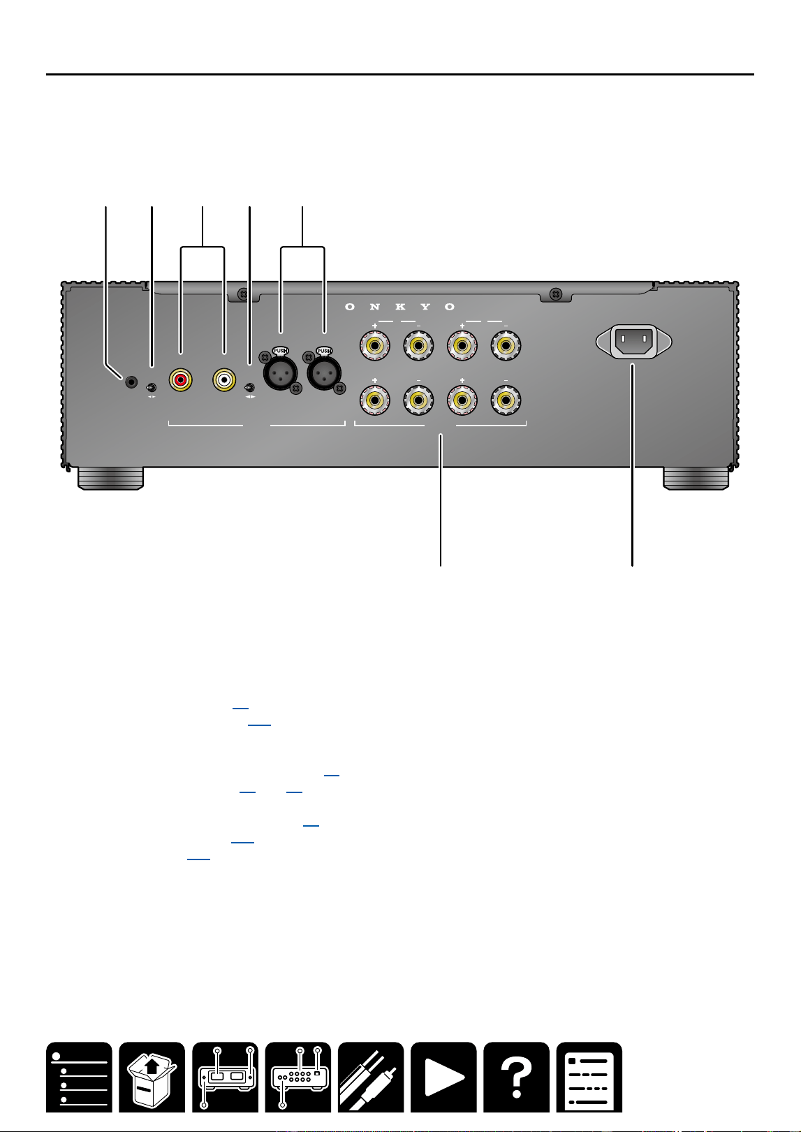
Rear Panel
Part Names
Rear Panel
INPUT
SELECT
A
12V
TRIGGER
IN
AUTO
STA ND BY
OFF ON
UNBALANCED
BALANCED
AUDIO IN
L
R L
R
L
R
L
R
SPEAKERS
B
AC INLET
A 2 3 4 5
6 7
A 12V TRIGGER IN jack ( →p9)
B AUTO STANDBY switch ( →p16)
You can use the Auto Standby (ASb) function. If the power amplifier receives no signal for 20 minutes, it will
automatically enter standby mode.
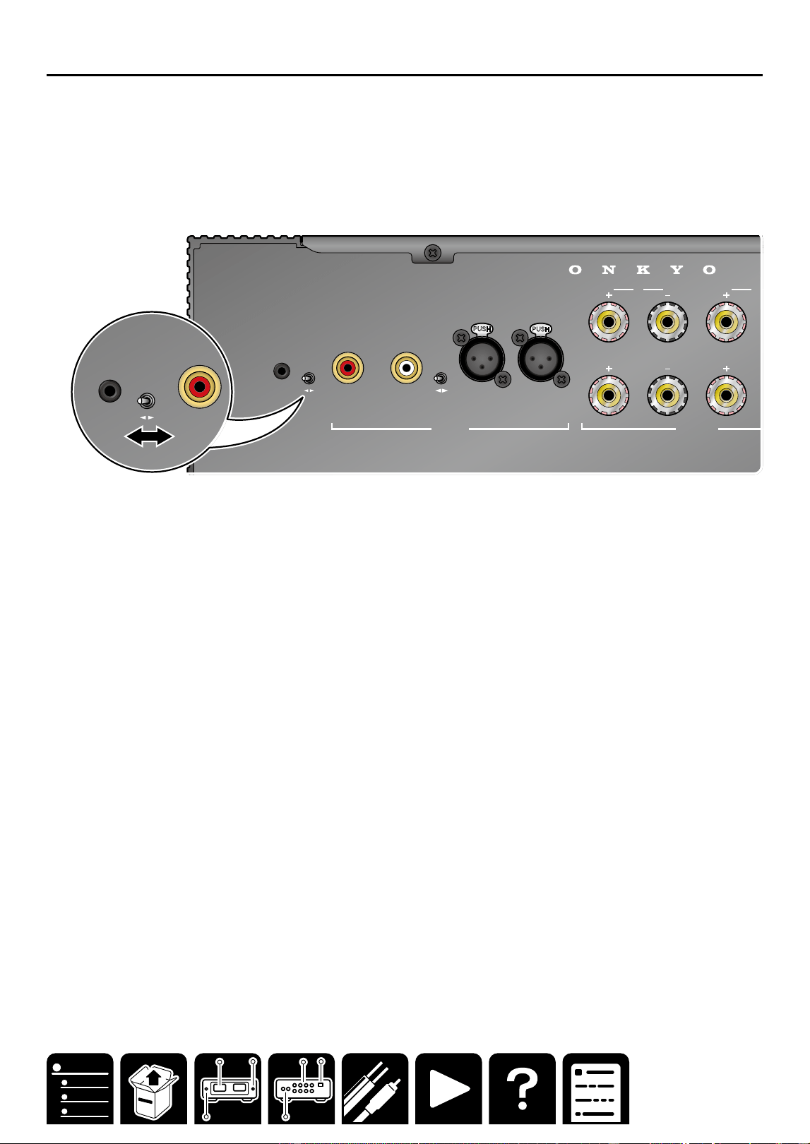
C AUDIO IN UNBALANCED L/R jacks ( →p7)
D INPUT SELECT switch ( →p7) ( →p8)
This switch is used to switch the audio input terminal.
E AUDIO IN BALANCED L/R jacks ( →p8)
F SPEAKERS terminals( →p10)
G AC IN terminal ( →p12)

6
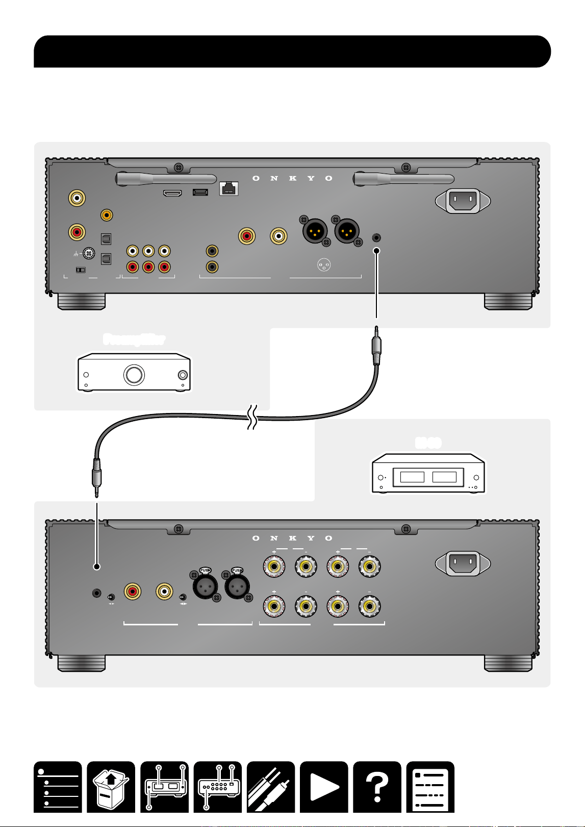
Connections
Connections
Connecting a Preamplifier 7
Connecting external control equipment
9
Connecting Your Speakers 10
Connecting the Power Cord 12
Note
・ The illustration of the preamplifier uses P-80, the
separately sold ONKYO preamplifier.
When connecting another preamplifier, also check
the instruction manual of the equipment to be
connected.
Connections
7
Connections
Connection using an unbalanced RCA cable
An unbalanced RCA cable (a) is a typical analog audio cable widely used for connection of audio equipment.
Preamplifier
Preamplifier
M-80
M-80
INPUT
SELECT
A
12V
TRIGGER
IN
AUTO
STA ND BY
OFF ON
UNBALANCED
BALANCED
AUDIO IN
L
R L
R
L
R
L
R
SPEAKERS
B
AC INLET
SUBWOOFER
L
R L
R
CD
COAXIAL IN
OPT IN
OPT OUT
CD
AUDIO IN DIGITAL AUDIO IN PRE OUT
PHONO
L
R
MM MC
GND
L
R
USB ETHERNET
5V
/
1A
TV
(
ARC
)
2 HOT
3 COLD
1 GND
ANALOG
1
ANALOG
2
1
2
AC INLET
INPUT
SELECT
UNBALANCED
BALANCED
AUDIO IN
R
12V
TRIGGER
OUT
aa
Connecting a Preamplier
8
Connections
Connection using a balanced XLR cable
A balanced XLR cable (a) attenuates audio signals less than an unbalanced RCA cable, minimizing noise. This
cable is suited when a long cable is required to connect to equipment remotely located.
PreamplifierPreamplifier
M-80
M-80
INPUT
SELECT
A
12V
TRIGGER
IN
AUTO
STA ND BY
OFF ON
UNBALANCED
BALANCED
AUDIO IN
L
R L
R
L
R
L
R
SPEAKERS
B
AC INLET
SUBWOOFER
L
R L
R
CD
COAXIAL IN
OPT IN
OPT OUT
CD
AUDIO IN DIGITAL AUDIO IN PRE OUT
PHONO
L
R
MM MC
GND
L
R
USB ETHERNET
5V
/
1A
TV
(
ARC
)
2 HOT
3 COLD
1 GND
ANALOG
1
ANALOG
2
1
2
AC INLET
12V
TRIGGER
OUT
INPUT
SELECT
A
UNBALANCED
BALANCED
AUDIO IN
R L
L
R
L
R
SPEAKERS
B
1 GND
2 HOT
3 COLD
a
a
・To remove the XLR cable from this unit, press and hold the connector button (b), and pull the cable.
9
Connections
When connected to a preamplifier, etc. with 12V TRIGGER OUT terminal mounted, this unit can be turned on or
enter the standby state by interlocking the power-on operation of the equipment.
・Use the supplied monaural mini-plug cable (a) for connection.
・ When using a commercially available cable, use a monaural mini-plug cable (φ3.5 mm) without resistance. Do
not use a stereo mini-plug cable.
M-80
M-80
PreamplifierPreamplifier
INPUT
SELECT
A
12V
TRIGGER
IN
AUTO
STA ND BY
OFF ON
UNBALANCED
BALANCED
AUDIO IN
L
R L
R
L
R
L
R
SPEAKERS
B
AC INLET
SUBWOOFER
L
R L
R
CD
COAXIAL IN
OPT IN
OPT OUT
CD
AUDIO IN DIGITAL AUDIO IN PRE OUT
PHONO
L
R
MM MC
GND
L
R
USB ETHERNET
5V
/
1A
TV
(
ARC
)
2 HOT
3 COLD
1 GND
ANALOG
1
ANALOG
2
1
2
AC INLET
12V
TRIGGER
OUT
a
a
Connecting external control equipment
10
Connections
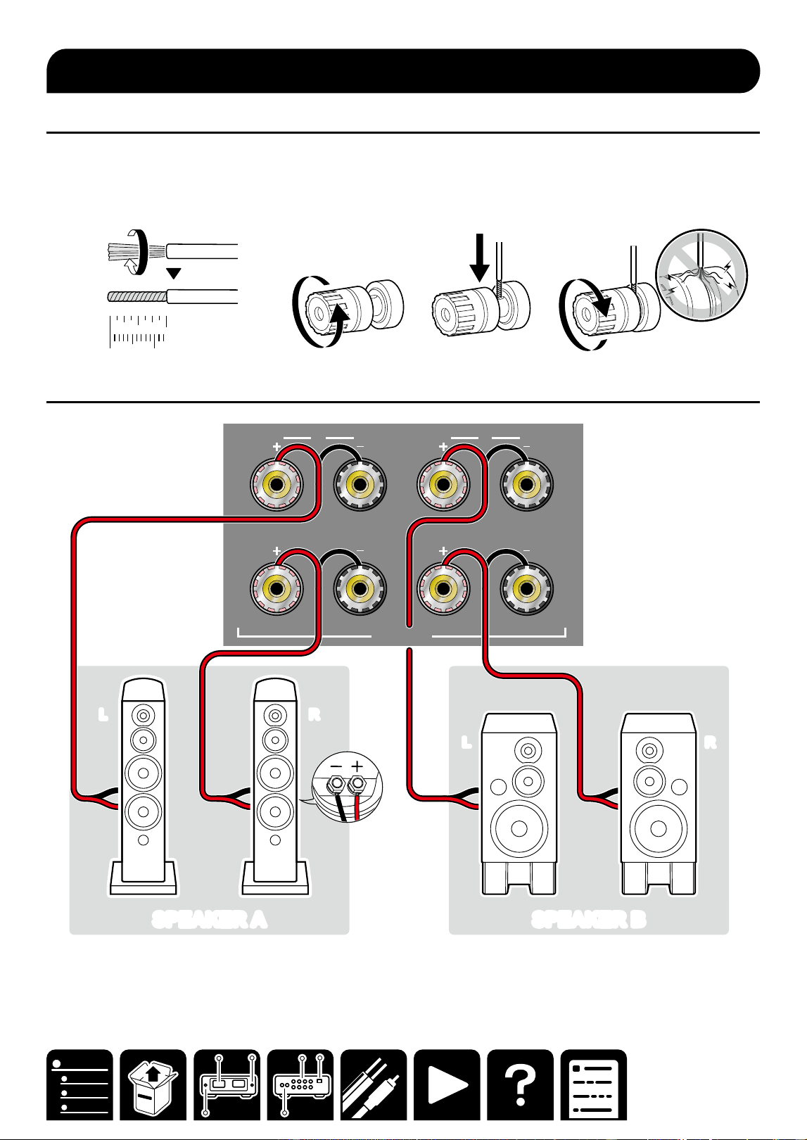
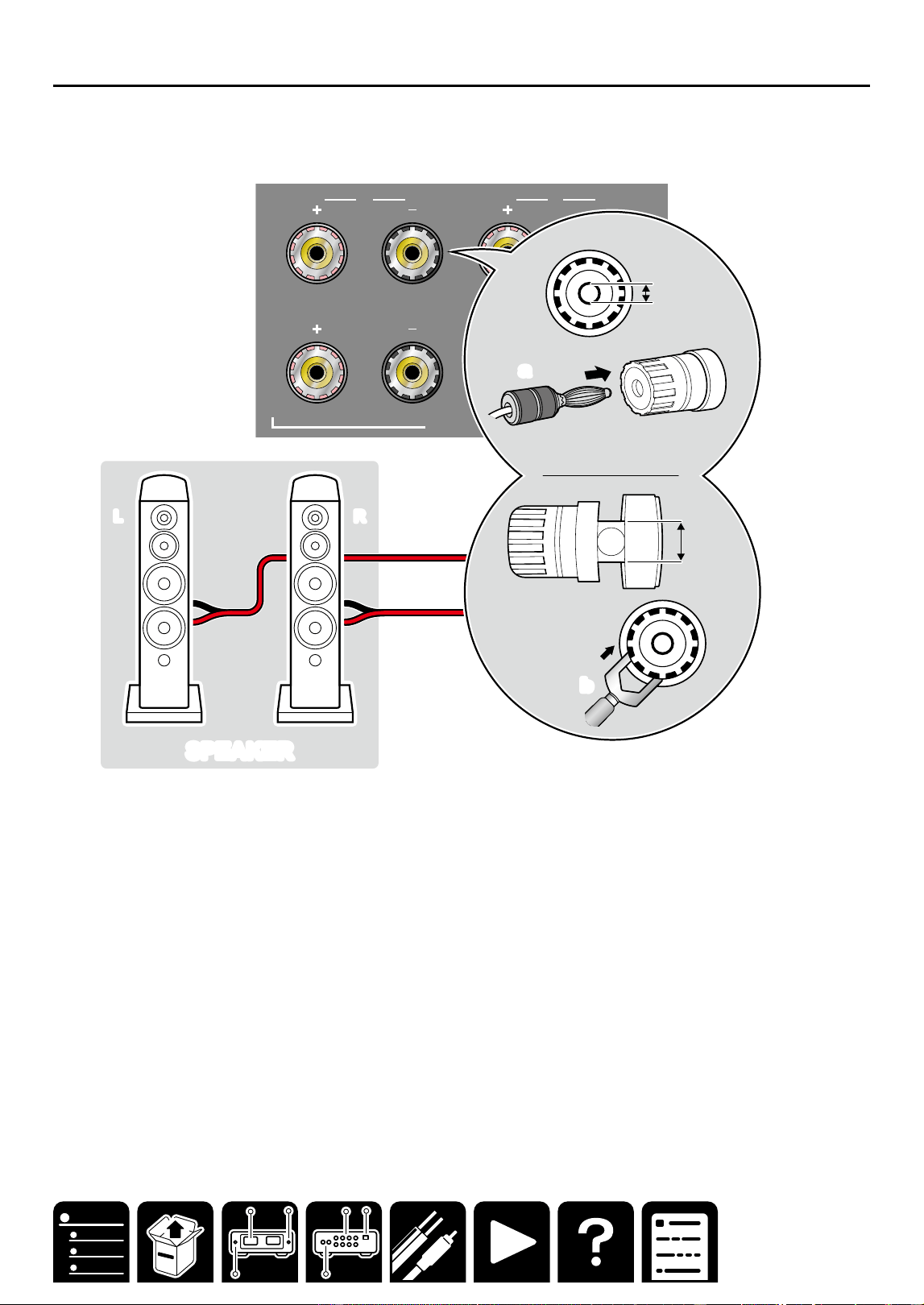
Preparation
・ When using only SPEAKER A or SPEAKER B, use a speaker with an impedance of 4 Ω to 16 Ω.
When using SPEAKER A and SPEAKER B at the same time, use speakers with an impedance of 8 Ω to 16 Ω.
・Firmly twist the core wire of the speaker cable, and insert it to the speaker terminal of this unit.
1/2˝
12 mm
General connection
A
L
R
L
R
SPE AKERS
B
LL
RR
SPEAKER A
SPEAKER A SPEAKER BSPEAKER B
LL
RR
Connecting Your Speakers
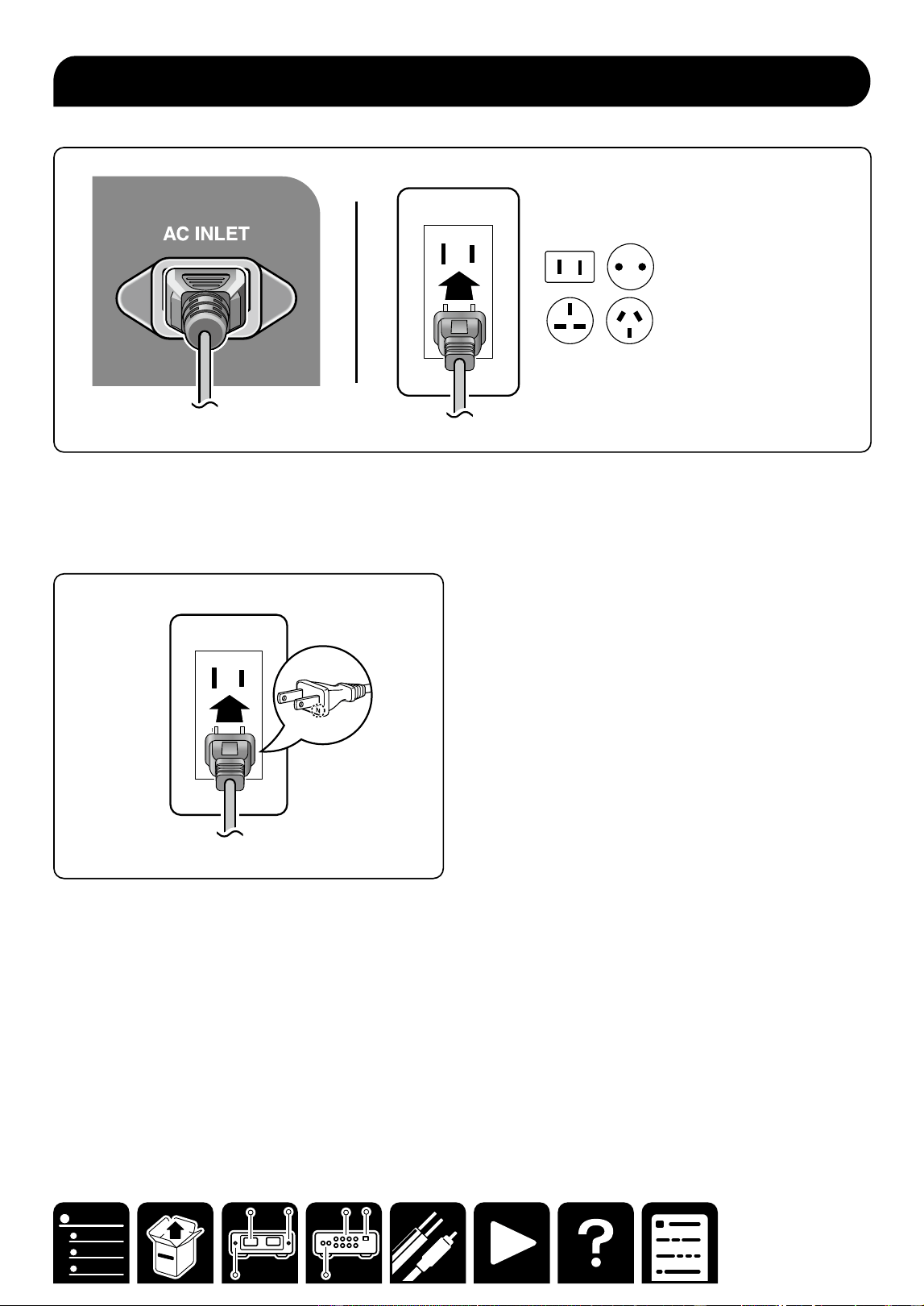
12
Connections
Connect the power cord after all the connections are completed.
Note
Japan model: Adapt the power source polarity for enhancement of the sound quality. Align the N-printed side
of the power plug supplied with this unit with the longer groove of the outlet, and insert the power plug. If both
grooves of the outlet are the same in length, either side can be connected.
Connecting the Power Cord

14
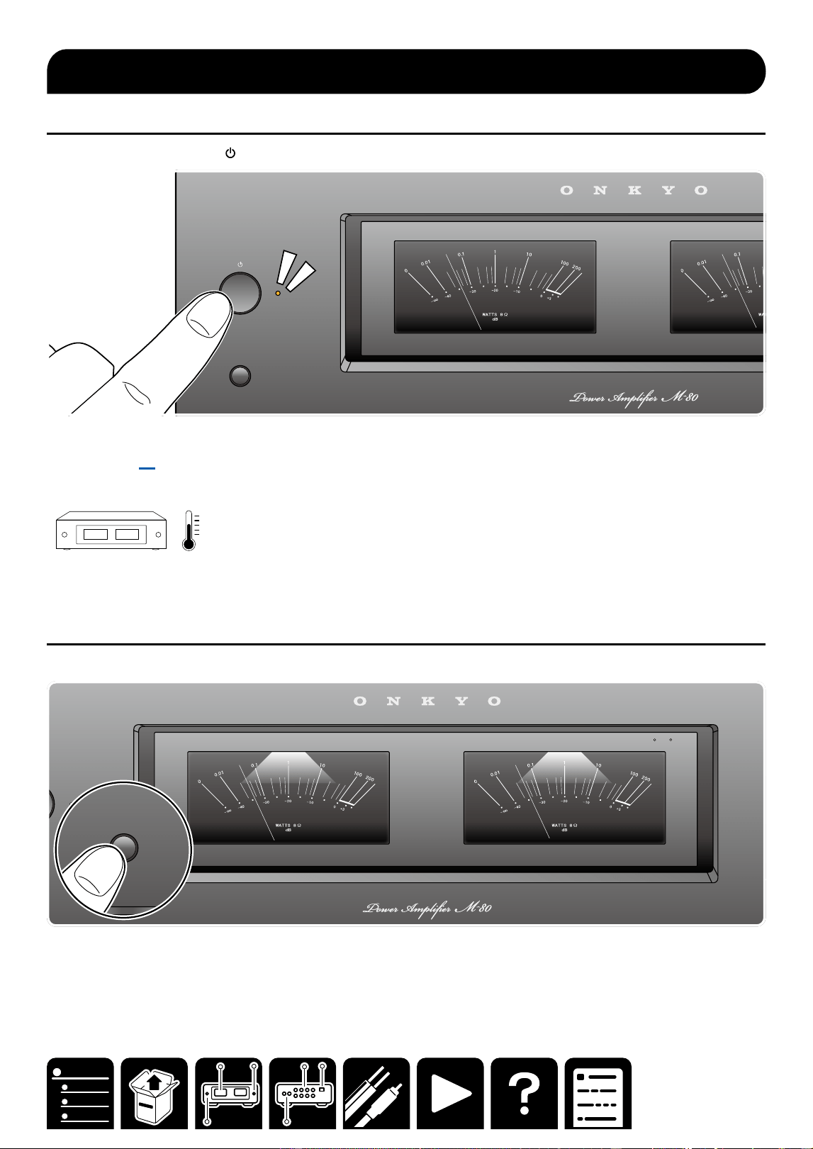
Playback
Power ON/OFF
1. Press the ON/STANDBY button on the front panel.
BACKLIGHTS
・ Using the supplied monaural mini-plug cable allows for interlocking of an external device with power ON/
standby. ( →p9)
Note
Warming up the unit for 10 to 30 minutes stabilizes the temperature of internal components of the unit, and
enhances the expressiveness of sound.
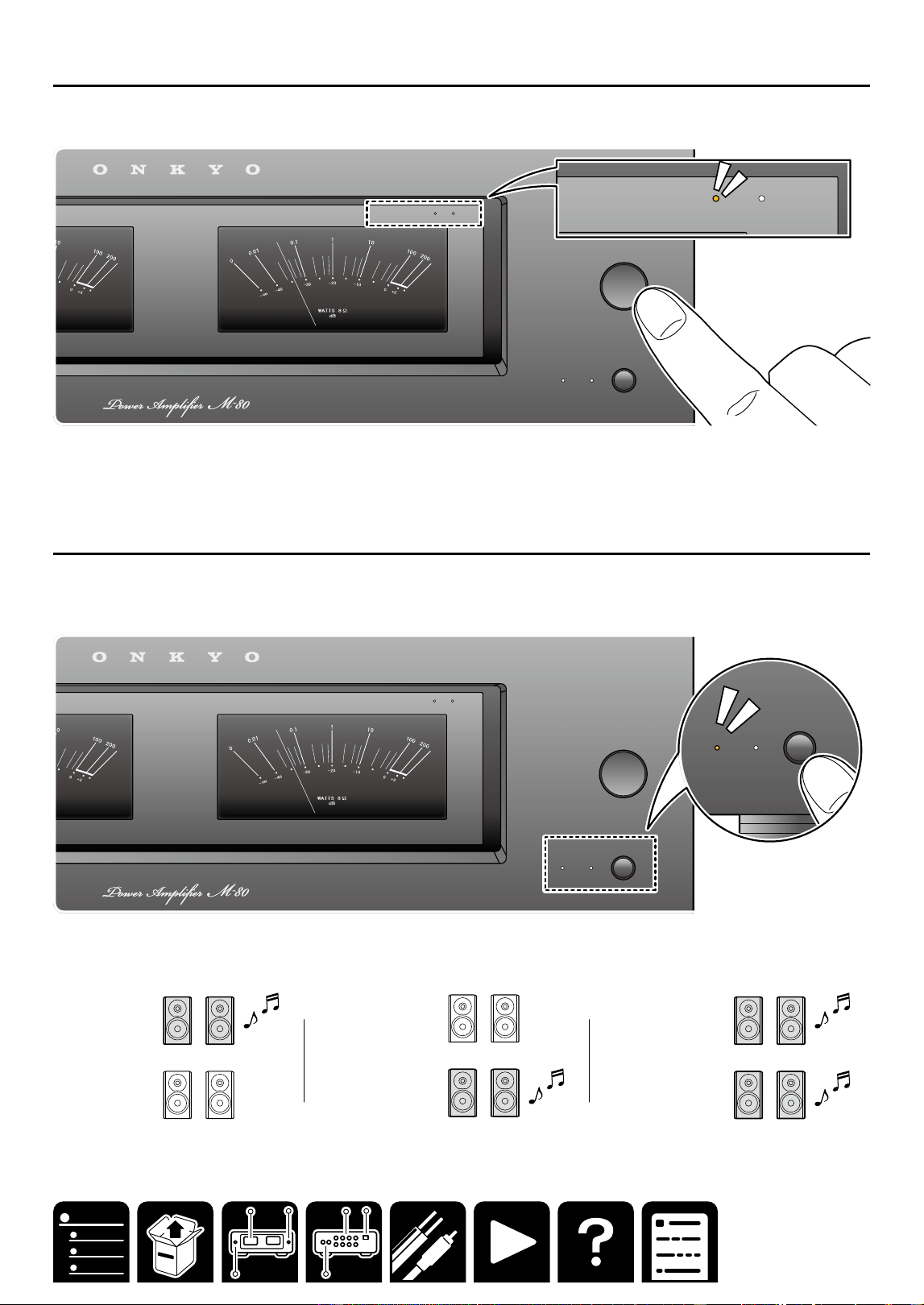
Backlight ON/OFF
1. Press the BACKLIGHTS button on the front panel.
BACKLIGHTS
A
METER RANGE
x
1
x
10
BACKLIGHTS
Basic Operations
15
Playback
Switching the Power Meter Range
1. Press METER RANGE repeatedly to switch METER RANGE in the following order:
×1 (default), ×10, Off
SPEAKERS
BA
METER RANGE
METER RANGE
x
1
x
10
METER RANGE
x
1
x
10
Note
The number of watts indicated on the meters corresponds to the actual output level when driving speakers rated
at 8 ohms. When driving speakers rated at 4 ohms, the output is actually twice that shown on the power meters.
Switching speakers
When you have connected two sets of speakers to this unit, you can select which set to output the sound.
1. Press the SPEAKERS button on the front panel.
The selection changes in the order SPEAKER A, SPEAKER B, SPEAKER A+B with each press.
SPEAKERS
BA
METER RANGE
METER RANGE
x
1
x
10
SPEAKERS
BA
Note
When using only SPEAKER A or SPEAKER B, use a speaker with an impedance of 4 Ω to 16 Ω.
When using SPEAKER A and SPEAKER B at the same time, use speakers with an impedance of 8 Ω to 16 Ω.
SPEAKER A
4Ω ~ 16 Ω
SPEAKER B
4Ω ~ 16 Ω
SPEAKER A
4Ω ~ 16 Ω
SPEAKER B
4Ω ~ 16 Ω
SPEAKER A
8Ω ~ 16 Ω
SPEAKER B
8Ω ~ 16 Ω
16
Playback
Setting Auto Standby (ASb)
When AUTO STANDBY is turned ON side, the power amplifier will automatically enter Standby mode if the power
amplifier receives no signal for 20 minutes.
・ When ASb (Auto Standby) is set to ON, the power indicator and power meter blink for 30 seconds immediately
before the unit automatically enters the standby state.
1. Set ON/OFF by switching the AUTO STANDBY switch.
ON: ASb enabled.
OFF: ASb disabled.
・When set to off, power consumption increases as the power continues to turn on.
INPUT
SELECT
A
12V
TRIGGER
IN
AUTO
STANDBY
OFF ON
UNBALANCED
BALANCED
AUDIO IN
L
R L
R
L
R
SPEAKERS
B
INPUT
SELECT
A
12V
TRIGGER
IN
AUTO
STANDBY
OFF ON
UNBALANCED
BALANCED
AUDIO IN
L
R L
R
L
R
SPEAKERS
B

17
Troubleshooting
Troubleshooting
When the unit is operating erratically
The problem may be solved by resetting the unit to restore all settings to the default states at the time of
purchase.
Reset procedure
1. Turn on the power of the unit, and wait for approx. 10 seconds.
2. While pressing and holding the SPEAKERS button, press the ON/STANDBY button two times.
・All indicators blink during rest.
3. When reset is complete, the unit enters the standby state.
Troubleshooting: The power does not turn on.
If the problem persists even after the AC cord is reconnected, the unit failure may have occurred.
Troubleshooting: No sound is delivered from the right or left speaker.
A contact failure or disconnection of the cable may have occurred. Reconnect the cable or use another cable and
check the condition.
Troubleshooting

18
General Specifications
North America and Japan
models
■ Amplier Section
Rated Output Power
(North America models)
With 8 ohm loads, both channels driven, from 20 Hz-
20 kHz; rated 130 watts per channel minimum RMS
power, with no more than 0.08% total harmonic
distortion from 250 milliwatts to rated output. (FTC)
(Japan models)
2 ch x 130 W at 8ohms, 20-20,000Hz, 2ch driven of
0.08% THD (JEITA)
THD+N (Total Harmonic Distortion + Noise)
・0.08% (20 Hz - 20,000 Hz, Rated output power)
■ General
・ Power Supply
AC 120 V, 60 Hz (North America model)
AC 100V, 50/60 Hz (Japan model)
・ Power Consumption
445 W (North America model)
385 W (Japan model)
・ Standby mode
0.2 W (North America model)
0.2 W (Japan model)
・ Dimensions (W × H × D)
435 mm × 135 mm × 345 mm
17-1/8" × 5-5/16" × 13-9/16"
・ Weight
11.4 kg (25.1 lbs.)
Europe models
■ Amplier Section
Rated Output Power
2 ch × 140 W at 4 ohms, 1 kHz, 2 ch driven of 1%
THD(IEC)
THD+N (Total Harmonic Distortion + Noise)
・0.08% (20 Hz - 20,000 Hz, Rated output power)
■ General
・ Power Supply
AC 220-240 V, 50/60 Hz
・ Power Consumption
425 W
・ Standby mode
0.3 W
・ Dimensions (W × H × D)
435 mm × 135 mm × 345 mm
17-1/8" × 5-5/16" × 13-9/16"
・ Weight
11.4 kg (25.1 lbs.)
Asia and Oceania models
■ Amplier Section
Rated Output Power
2 ch × 140 W at 4 ohms, 1 kHz, 2 ch driven of 1%
THD(IEC)
THD+N (Total Harmonic Distortion + Noise)
・0.08% (20 Hz - 20,000 Hz, Rated output power)
■ General
・ Power Supply
AC 220-240 V, 50/60 Hz
・ Power Consumption
425 W
・ Standby mode
0.3 W
・ Dimensions (W × H × D)
435 mm × 135 mm × 345 mm
17-1/8" × 5-5/16" × 13-9/16"
・ Weight
11.4 kg (25.1 lbs.)
Common to all destinations
Input Sensitivity and Impedance
・1000 mV/52 kΩ (LINE(RCA))
・1000 mV/20 kΩ (LINE(XLR))
Frequency Response
・10 Hz - 100 kHz/+1 dB, –3 dB
Signal to Noise Ratio
・106 dB (IHF-A, LINE IN, SP OUT)
Supported impedance of Speakers
・4 Ω - 16 Ω (Speakers A or B)
・8 Ω - 16 Ω (Speakers A + B)
Input terminals
Analog
・2 (RCA IN×1, XLR IN×1)
Other terminals
・Speaker terminal ×4
・12V Trigger In jack ×1
General Specications
General Specications

SN 29404226A_EN
© Copyright 2025 Premium Audio Company Technology Center K.K. All rights reserved. ©Copyright 2025 Premium Audio Company
Technology Center K.K. Tous droits de reproduction et de traduction réservés.
O2509-1