

www.PyleUSA.com
2
PRECAUTIONS
• This unit is designed for negative ground 12-14.50 Volts (DC) operation only.
• Use speakers with an impedance of 4 Ohms
• Avoid installing the unit where:
• It would be subject to high temperatures, such as from direct sunlight or hot air
from the heater.
• It would be exposed to rain or moisture.
• It would be subject to dust or dirt.
• If your vehicle or boat is parked in direct sunlight and there is a considerable
rise in temperature inside the car, allow the unit to cool off before operation.
• When installing the unit horizontally, be sure not to cover the heatsink ns with
the oor carpet.
• If this unit is placed too close to the resources radio, an interference may occur.
In this case, separate the amplier from the car radio.
• This power amplier employs a protection circuit to protect the transistors and
speakers if the amplier malfunctions. Do not attempt to test the protection
circuits by covering the heatsink or connecting improper loads.
• Do not use the unit with a weak auto battery as its optimum performance
depends on a normal battery supply voltage.
• For safety reasons, keep the volume of your audio system moderate so that you
can still hear normal traffic sounds in a reasonable distance.
WIRING INSTRUCTIONS
POWER CONNECTION
The battery terminal (BATT ) must be connected directly to the positive terminal of
the vehicle battery to provide an adequate voltage source and minimize noise.
Connecting the battery terminal lead to any other point (such as the fuse block)
will reduce the power output and may cause noise and distortion. Use only #12
gauge or thicker (smaller gauge #) wire for this lead and connect it to the terminal
of the battery after all other wiring is completed.
GROUND CONNECTION
The ground terminal (GND) connection is also critical to the correct operation of
the amplier. Use a wire of the same gauge as the power connection (#8 or thicker)
and connect it between the ground terminal (GND) of the amplier and a metal
part of the vehicle close to the mounting location. This wire should be as short as
possible and any paint or rust at the grounding point should be scraped away to
provide a clean metal surface to which the end of the ground wire can be screwed
or bolted.

www.PyleUSA.com
3
REMOTE TURN-ON CONNECTION
The amplier is turned on by applying +12V to the remote turn-on terminal (REM).
The wire lead to this terminal should be connected to the "Auto-Antenna" lead
from the vehicle/or boat stereo resources which will provide the +12V only when
the stereo resources is turned on . If the car stereo does not provide an "Auto-
Antenna" lead, the remote turn-on lead may be wired to an "Accessory" or "Radio"
terminal in the vehicle’s/or boat’s fuse block. This will turn the amplier on and off
with the ignition key, regardless of whether the stereo resources is on or off.
The remote turn-on lead does not carry large currents. So #16 gauge wire may be
used for this application.
SPEAKER CONNECTIONS
Depending on the type and number of speakers used with the amplier wire them
to the speaker terminals as per the appropriate wiring diagram. For most applications
#18 gauge wire should be used for the speaker leads but in no case thinner than
#16 gauge. For leads is excess of 10 feet #12 gauge is recommended. When wiring
the speakers, pay careful attention to the polarity of the terminals on the speakers
and make certain they correspond to the polarity of the corresponding terminals
on the amplier. Do not ground any speaker leads to the chassis of the vehicle/or
boat.
OPERATION
After the amplier has been installed and all connections have been made carefully
and securely, turn the radio on so that the amplier is switched on automatically.
After a short power-on period, the amplier reaches its full performance. Now turn
up the volume slowly using the volume control of the radio. If there is no sound or
only a distorted replay, switch off the radio immediately - the amplier will also
switch off automatically - and check if all connections have been made correctly.
GND (-) = GROUND CONNECTION
Connect the GND terminal to the chassis ground of your vehicle/or boat and
take care of best electric and mechanic contact. In doing so, drill a hole into the
vehicle/or boat chassis near the amplier then remove color, dirt or any other
substance from the ground point. Thereafter fasten the cable end with added ring
terminal by using a screw. Ensure that the ground connection is as short as possible
and that the cable diameter is sufficient (min 4mm). Route the ground cables from
the radio and all other equipment parts, like equalizer, active crossover network or
other ampliers, to the same ground point.
www.PyleUSA.com
4
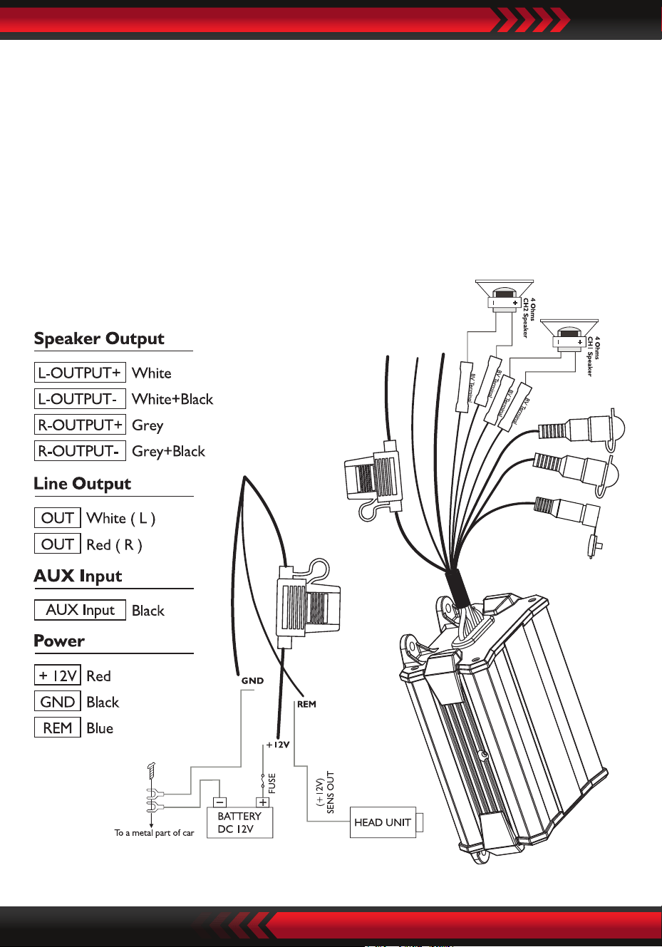
Line Out L
Line Out R
AUX Input
Black
Blue
+12V
Red
L
-
O
U
T
P
U
T
+
(
W
h
i
t
e
)
L
-
O
U
T
P
U
T
-
(
W
h
i
t
e
+
B
l
a
c
k
)
R
-
O
U
T
P
U
T
+
(
G
r
e
y
)
R
-
O
U
T
P
U
T
-
(
G
r
e
y
+
B
l
a
c
k
)
+ 12V = POWER SUPPLY
Connect the BATT terminal to the positive pole of the battery with a lead cable and
add a fuse into the power cable in a distance of not more than 30 cm from the
battery. The lead cable’s diameter should be at least 4 mm’ for a length of 3m and
6mm” for a length of 6m.
REM (ON/OFF) REMOTE CONTROL
Connect the REM terminal to the automatic antenna connector of your vehicle/or
boat radio. Now when turning on and off your vehicle/or boat radio, the amplier
automatically switches ON and OFF. A cable diameter of 0.5mm2 is sufficient.
SPEAKERS CONNECTIONS
POWER CONNECTION LEADS

www.PyleUSA.com
5
NOTES ON THE POWER SUPPLY
• Connect the +12V power input lead only after all other leads have been connected.
• Be sure to connect the ground wire of the unit securely to a metal part of the
vehicle/or boat.
• Loose or faulty connection may cause amplier malfunction
• REM: The unit is turned on by applying +12 Volts to this terminal. This terminal
does not draw heavy current like the tow Power Terminals so a thinner connecting
wire is acceptable. Standard 18 GAUGE is ne and the standard color is red. If the
radio is equipped with a Power Antenna control wire, it can drive this terminal.
If the Power Antenna wire is already in use, you can still splice into it. With this
method, the unit will turn ON automatically with the radio.
• Use the power supply lead with a fuse attached whose value is the same as original
fuse.
• Place the fuse in the power supply lead as close as possible to the car battery.
• During a full power operation, Maximum current will run through the system.
Therefore, make sure that the leads to be connected to the +12V and GND
terminals of the unit respectively must be larger than 18-Gauge (AWG.18) proper
Bridged operation. If only mono signal is available, a "Y" adapter is required.
FUSE REPLACEMENT
If the fuse blows, check the power connection and replace the fuse. If the fuse blows
again after replacement, there may be an internal malfunction. In this case, consult
your dealer.
WARNING
• Use the specied amperage fuse. Use of a higher amperage fuse may cause serious
damage.
PROTECTION CIRCUIT
This amplier is provided with a protection circuit which operates in the
following cases when:
• the unit is overheated.
• the speaker terminals are short circuited.
HOW TO PROCEED IN CASE OF FAULTS
No Function:
• The connection cable is not connected correctly (=terminal +12V/GND/REM).
Ensure that all connections and mechanic contact and that the jacket has been
removed. The fuse is defective-pay attention to the correct value of a new fuse!

No Sound:
• Speaker cable or speaker plug are not connected correctly.
• The plus and minus wires of the speaker cable have contact, thus eliminate the
short circuit. If you use Pay attention only 4 ohm load speaker is allowed. No 2 ohm
or less impedance speaker connection is allowed.
Poor Sound Quality (Distortions):
• The speakers are overloaded, therefore turn down the volume level and check the
volume control positions.
No Stereo Sound And A Weak Bass:
• Speaker cables (+) and (-) are mixed up, unit wired out of phase.
INTERFERENCE
All cables can source and create interference. The power cable and Cinch/RCA
audio cable are very prone to interference; the remote cables are less prone.
There is often interference caused by the generator (piping), ignition (cracking) or
other vehicle/or boat electronic parts. Most of these problems can be eliminated
by correct and careful cabling. In doing so, here are the following guidelines:
• Use only a screened audio cable for the wiring between “low level in” of the
amplier and RCA or DIN output of the radio.
• Lay the signal, speaker and power cables separately with enough distance from
one another and also from each other car cable. If not possible, you can lay the
circuit and ground cable together with the serial cables. Audio and speaker cable
should be as far away from these as possible. The REM cable to the automatic
antenna output of the radio can be laid together with the signal cables.
• Avoid ground loops by laying the ground wiring of all components to a center
point in a star-like way. you can nd the best central point in measuring the
voltage directly at the battery. Now compare this voltage value with the chosen
ground point and the (+) terminal of the amplier. If measured voltage is only
slightly different, you’ve found the correct central. Otherwise you have to look for
another point. You should measure with the ignition point for earth being switched
on and additionally switched on consumers (rear window heating and light).
• If there are pickups from external electrical sources into the speaker cables, divide
the core leads and twist them together.
• If there are noises from the car electrics, add an interference suppression choke
into the power wiring.
• If there are humming noises, use thicker ground cables or add further ground
cables to the chassis.
• To reduce contact resistance and bad and loose contacts, please solder the cable
ends or use multi core cable ends, spade terminals or others.
www.PyleUSA.com
6
www.PyleUSA.com
7
Gold Plated spade terminal are free of corrosion and have the lowest contact
resistance.
• Should all these meaures be without any success, the use of a ground loop
isolator may solve the problem.
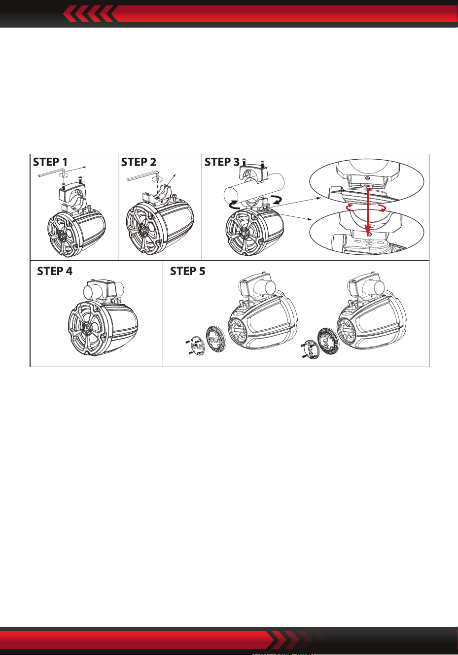
PLUTV60CH Speaker Installation
Speaker Mounting suggestion as below:
Step 1: Removing the top half of clamp
Put the PLUTV60CH speaker in a safe place.
Using the 1/4” Hex key, remove the top clamp bolts.
Step 2/3: To adjust mounting clamp angle and speaker position
Diagram A is to show there are four round pins underneath the bottom
base of aluminum die cast clamp, which can be inserted and xed to four
round notch holes on top of plastic cabinet as diagram B shows by every
45 degrees adjustment either at clockwise or counter clockwise direction.
Through such design, user can change the angle of swivel clamp, use the
5/16” hex key to loose the center screw a little bit and lift the bottom clamp
to twist speaker angle by every 45 degrees to get the optimal angle you
want. Then re-making sure the pins on base of bottom clamp are inserted
and sits on notch holes on top of plastic cabinet at and seamlessly.
Then re-tighten the center hex screw to secure the bottom clamp strongly.
5/16”
Hex key
1/4”
Hex key
45°
Diagram A
Diagram B

Step 4: Securing clamp bolts
Using the correct rubber pads (labeled for O.D.) install on both top and
bottom half of clamps. 3.15” x 1.2” x 0.2” rubber pads for 1.75” O.D. 3.15” x
1.2” x 0.08” rubber pads for 2” - 3” O.D. Using the 1/4” Hex bit socket hand
tighten the bolts evenly (both sides should have the same spacing
between bolts).
Step 5: Option for adjustable PYLE logo---Unbolt the screws rst, adjust the logo
direction, then re-x screws.
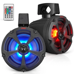
Features:
• Water-Resistant Rated Speakers
• SQL Audio Power Sports Amplier System Kit
• 2-Channel Marine Audio Amplier
• Marine Grade Rugged Construction
• Weather-Resistant Connectors
• Integrated Power Wiring Harness
• Perfect for Custom Installations & Applications
• Ability to Connect & Stream Audio from External Devices
• Aux (3.5mm) Input
• Pre-Amp RCA Out to Any OEM/Factory-Made Mono-Block/Full-Range Amplier
• Speaker Wiring Connectivity
• Anti-Thump Turn-On
• Soft Turn On/Off
• Overload & Power Protection Circuitry
• Used for Watercraft & Portable Mobile Vehicle Sound Systems
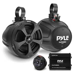
What’s in the Box:
•
(2) 6.5’’-inch Marine Speakers
• (2) Speaker Connection Wires, 6.5' ft.
• (2) 3” Aluminum Mounting Brackets (Pre-Installed on Speakers)
• (4) 3.15” x 1.2” x 0.2” Inches Rubber Pads
• (4) 3.15” x 1.2” x 0.08” Inches Rubber Pads
• (4) M8x55mm Hexagon Socket Head Cap Screws
• (4) M8x35mm Hexagon Socket Head Cap Screws (Pre-Installed)
• (1) Compact 2 Channel Marine Amp
• (4) Butt Connector 16-22AWG
• Screw Bag
• (4) Nylon Wire Straps
www.PyleUSA.com
8

www.PyleUSA.com
9
Amplier Technical Specs:
•
Amplier Type: 2-Ch. Audio Component
• Power Output: 1200 Watt MAX
• 2 x 50 Watts RMS @ 4 Ohm
• 2 x 150 Watts MAX @ 4 Ohm
• Marine Grade IP-X6 Rating
• T.H.D:≤ 1%
• S/N Ratio:≥ 80dB
• Channel Separation:≥ 65dB
• Fuse: 15A
• Power: DC 12V
• Amp Dimensions (L x W x H): 6” x 3.86” x 2.36” –inches
Marine / PowerSports Tower Technical Specs:
•
Power Output: 1200 Watts
• Marine Grade Waterproof Rating: IP-X6
• Speaker Size: 6.5’’ -inch (Each)
• Speaker Style: Passive Speakers
• Speaker Type: Polypropylene Cone, Butyl Rubber Surround (x2)
• Tweeter Type: Neodymium Dome (x2)
• Impedance: 4 Ohm
• Magnet Type: 32 oz. Circuit
• Mid-Woofer Voice Coil Type: 1'', TIL
• Sensitivity: 92 dB +/- 2 dB @ 1M/1W
• Universal Mounting Brackets Roll-Bar/Roll-Cage Diameter: 1.75’’ ~ 3.0’’ –inches
• 1.75”~2” for Motorsports/Powersports Application.
• 2.25”~3” for Marine Application.
• Speaker Dimensions: 8.1’’ x 8.9’’ x 10.5’’ -inches, with Bracket (-Each)