EN
Operation Manual
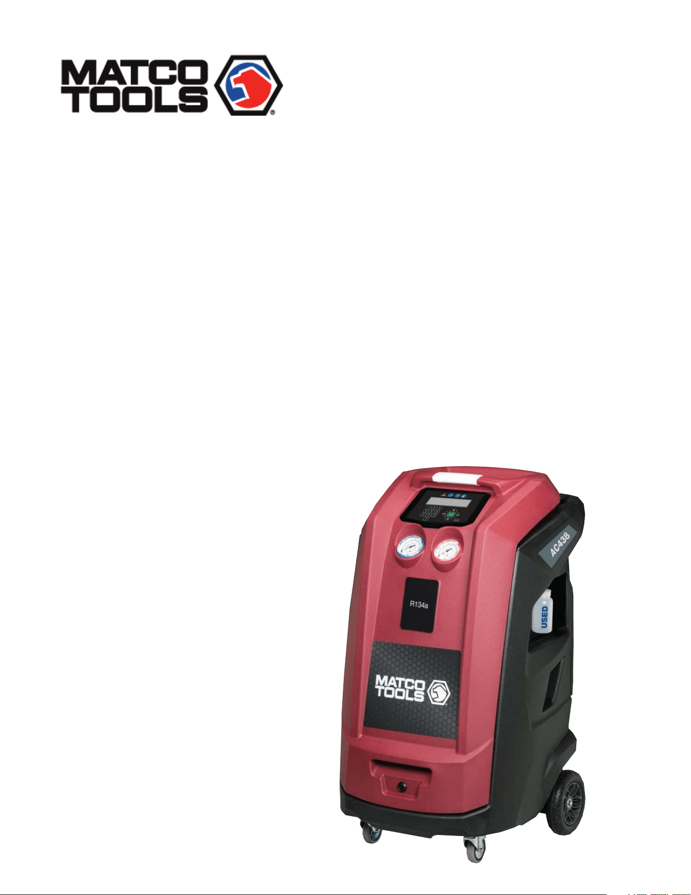
A/C Service Equipment
R134a KEYPAD AUTOMATIC RRR
AC438
1901016-85

1. Symbols use 4
2. Important notes 4
3. Product description 8
4. Technical features 12
5. Equipment installation 13
Contents
1.1 In the documentation 4
1.1.1 Warning notices structure + meaning 4
1.1.2 Symbols in this documentation 4
1.2 On the product 4
7. Setup 15
7.1 AC438 15
8. A/C service preparation 17
8.1 Preliminary operations 17
8.2 Non-condensible gas discharge 17
8.3 Charge modes 17
9. A/C system service 18
9.1 Automatic cycles 18
9.2 Manual cycles 19
.
7.1.1 EcoLOCK 15
7.1.2 Recharge mode 15
7.1.3 Pressure check 15
7.1.4 Multipass 15
7.1.5 Report saving mode 15
7.1.6 Unit of measure 15
7.1.7 Clock adjustment 16
7.1.8 Setting language 16
7.1.9 Startup screen 16
7.1.10 Default setup 16
8.3.1 Quick mode 17
8.3.2 Zero tolerance mode 17
9.2.1 Recovery process 19
9.2.2 Vacuum process 19
9.2.3 Recharge 20
9.2.4 Flushing (with optional accessories) 20
9.2.5 Pressure check 20
9.2.6 Hose emptying 20
3.1 Application 8
3.2 Scope of delivery 8
3.3 Description of unit 9
3.4 User interface 10
3.4.1 Selection and function keys 10
3.4.2 Input keys 10
2.4.1 AC438 6
2.5 Safety devices 7
3.4.3 Display screen 11
3.3.4 Main menu options 11
3.5 Unit features 11
3.5.1 EcoLOCK quick couplers 11
3.5.2 Locking caster brakes 11
3.5.3 Power supply cable and switch 11
3.6 Functional description 12
2.1 User group 4
5.1 Unpacking AC438 13
5.2 Load cell screw release 13
.
6. Commissioning 14
6.1 Connections and positioning 14
6.2 First start-up verification 14
.
2.2 Agreement 4
2.3 Obligation of contractor 5
2.4 Safety regulations 6
en | 2 | AC438 |
1901016-85

10. Maintenance 21
11. Spare parts 27
10.1 Maintenance interval 21
12. Disposal 27
12.1 A/C Service unit disposal 27
12.2 Recycled material disposal 27
12.3 Packaging disposal 27
13. Troubleshooting 28
13.1 AC438 28
14. Maintenance forms 30
15. Notes 39
14.1 Vacuum pump oil change 30
14.2 Filter dryer change 32
14.3 Refrigerant load cell calibration check 35
14.4 Other checks/maintenance/repairs 37
10.2 Filling internal refrigerant cylinder 21
10.3 Self leak test 22
10.4 Cylinder pressure check 22
10.5 Cylinder refrigerant view 22
10.6 Pressure zero 22
10.7 Counters 22
10.8 Long life pump test 23
10.9 Vacuum pump oil change 23
10.10 Replace filter dryer 24
10.11 Multipass 24
10.12 System info 24
10.13 Software update 25
10.14 Refrigerant weight accuracy check 25
10.15 Printer maintenance 26
10.16 Periodic checks 26
| AC438 | 3 | en
1901016-85
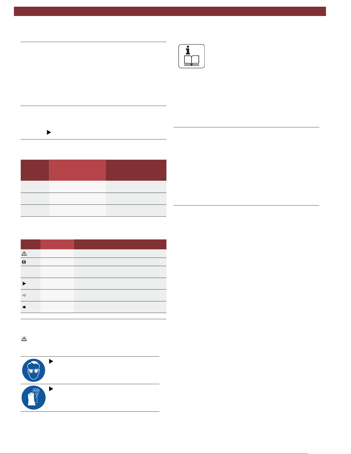
1. Symbols use
Warning notices warn of dangers to the user or people
in the vicinity. Warning notices also indicate the conse-
quences of the hazard as well as preventive action.
Warning notices have the following structure:
Warning
symbol
KEYWORD - Nature and source of hazard!
Consequences of hazard in the event of failure
to observe action and information given.
Hazard prevention action and information.
The key word indicates the likelihood of occurrence and the
severity of the hazard in the event of non-observance:
Severity of danger
if instructions not
observed
DANGER Immediate impending
danger
Possible impending
danger
Possible dangerous
situation
Death or severe injury
Death or severe injury
WARNING
CAUTION
Minor injury
1. 1. 2 Symbols in this documentation
Symbol Designation Explanation
t
Attention Warns about possible property damage
t
Information Practical hints and other useful information.
1.
2.
Multi-step
operation
One-step
operation
Instruction consisting of several steps
Instruction consisting of one step
Intermediate
result
An instruction produces a visible intermed-
iate result.
Final result There is a visible final result on completion
of the instruction.
1. 2 On the product
m
Observe all warning notices on products and ensure they
remain legible.
Wear protective goggles.
Wear protective gloves.
2. Important notes
Before start up, connecting and operating MATCO
products it is absolutely essential that the Original
instructions/owner’s manual and, in particular, the
safety instructions are studied carefully. By doing
so you can eliminate any uncertainties in handling MATCO prod-
ucts and thus associated safety risks upfront; something which
is in the interests of your own safety and will ultimately help avoid
damage to the device. When a MATCO product is handed over
to another person, not only the Original instructions but also the
safety instructions and information on its designated use must
be handed over to the person.
2.1 User group
The product may be used by skilled and instructed personnel
only. Personnel scheduled to be trained, familiarized, instructed
or to take part in a general training course may only work with
the product under the supervision of an experienced person.
All work conducted on pressurized equipment may be performed
by persons with sufficient knowledge and experience in the field
of refrigeration, cooling systems and coolants and, also be aware
of the risks involved in the use of pressurized devices.
2.2 Agreement
By using the product you agree to the following regulations:
Copyright
Software and data are the property of MATCO or its suppliers
and protected against copying by copyright laws, international
agreements and other national legal regulations. Copying or sell-
ing of data and software or any part thereof is impermissible and
punishable; in the event of any infringements MATCO reserves
the right to proceed with criminal prosecution and to claim for
damages.
1.1 In the documentation
1.1.1 Warning notices - Structure and
meaning
en | 4 | AC438 | Important notes
Keyword Probability of
occurence
1901016-85

Liability
All data in this program is based—where possible—on
manufacturer and importer details. MATCO does not
accept liability for the corrrectness and completeness
of software and data; MATCO shall not be liable for
damage caused by faulty software and data. Whatever
the event, MATCO’s liability is restricted to the amount
the customer actually pays for the product. This dis-
claimer of liability does not apply to intentional dam-
ages or damages caused by the gross negligence of
MATCO.
Warranty
Any use of non-approved hardware and software will
result in a modification to our product and thus to
exclusion of any liablility and warranty, even if the
hardware or software has in the meantime been removed
or deleted.
No changes may be made to our products. Our
products may only be used in combination with
original accessories and original service parts. Failing
to do so, will render null and void all warranty claims.
This product may only be operated using MATCO
approved operating systems. If the product is
operated using an operating system other than
the approved one, than our warranty obligation
pursuant to our supply conditions will be ren-
dered null and void. Furthermore, we will not be
held liable for damage and consequential damage
incurred through the use of a non-approved oper-
ating system.
2.3 Obligation of contractor
The contractor is obliged to ensure that all measures geared
towards the prevention of accidents, industrial diseases, and
labor-
related health risks are taken and measures towards
making the workplace fit for people to work in are carried out.
Electrical engineering in Germany is subject to the accident
prevention regulations of the trade association "Electrical Plant
and Equipment as under BGV A3 (previously VBG 4)". In all
other countries, the applicable national regulations acts or de
crees are to be adhered to.
Basic rules
Specifications for electrical systems (BGV A3)
The contractor is bound to ensure that all electrical equipment
and operating equipment is set up, modified and maintained by
skilled electricians only or under the guidance and supervision
of a skilled electrician in accordance with electrical engineering
principles.
Furthermore, the contractor must ensure that all electrical equip
ment and operating material is operated in keeping with electrical
engineering principles.
If a piece of electrical equipment or operating material is found to
be defective, i.e. it does not or no longer complies with electrical
engineering principles, the contractor must ensure that the fault
is rectified immediately and, in the event that imminent danger
exists, also ensure that the electrical equipment or the electrical
operating material is not used.
Tests (taking Germany as an example)
The contractor must ensure that all electrical systems and
equipment are tested by a qualified electician or under
the guideance of a qualified electrician to ensure they are in
proper working order:
—
—
—
At given intervals. Set intervals such as to ensure that
Before starting for the first time.
After modification or repair before starting for the first time.
faults that can be expected to occur are determined in
good time.
The test is to take the electrical engineering principles relating
hereto into account.
Upon request of the trade association, a test manual is to be
maintained into which specific entries are made.
Important notes | AC438 | 5 | en
1901016-85
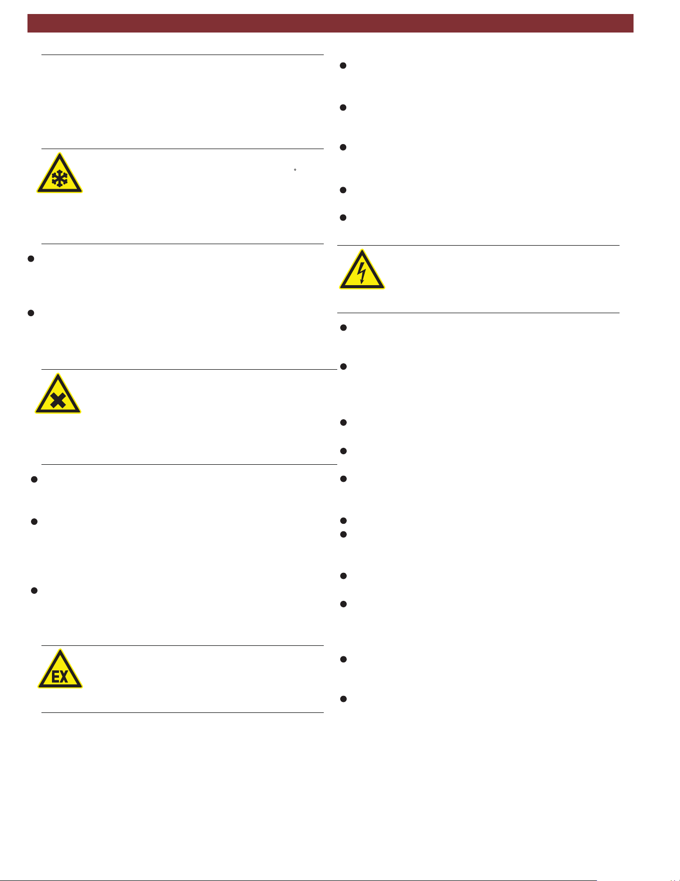
2.4 Safety regulations
2.4.1 AC438
Always carefully study and follow all the safety regulations
before using the MATCO product.
Avoid all skin contact with the refrigerant. The low
boiling point of the refrigerant (approx. -30 C) can
lead to frostbite. Should refrigerant come into con
tact with the skin, remove any moistened clothing
immediately and rinse the area of skin affected with
generous amounts of water.
Avoid all skin contact with the UV dye. Should UV dye come
into contact with the skin, remove any moistened clothing
immediately and rinse the area of skin affected with
generous amounts of water.
R134a is colorless, with weak characteristic smell and
heavierthan air. It may flow into repair pits. Should
refrigerant escape, provide for sufficient ventilation
(particularly in repair pits) and leave the workshop.
Never inhale refrigerant, dye and oil vapors. The
vapors can irritate the eyes, nose and respiratory
system. If liquid refrigerant or UV dye comes into
contact with the eyes, rinse them thoroughly with
water for 15 minutes. Then obtain medical attention
even if no pain is felt.
Never swallow UV dye. Should it be swallowed inadvertently,
never attempt to induce vomiting. Drink generous amounts of
water and obtain medical attention.
Before connecting the AC438 to a vehicle air condition
ing system or an external refrigerant bottle, make sure the
quick-release couplings are not leaking. Only ever use external
refrigerant bottles provided with safety valves and certified
inline with the applicable standards.
Before switching off the AC438, make sure all charging
and drainage operations have been completed. This prevents
damage to the unit and reduces risk of refrigerant escaping
into the environment.
Never use compressed air with R134a. Certain mix-
tures of air and R134a are highly flammable. Such
mixtures are a potential hazard and may lead to fire
or explosions and thus cause damage or injury.
Refrigerant extracted from a vehicle air conditioning system
may be contaminated with moisture, lubricant, dirt and traces
of other gases.
If the refrigerant has been contaminated by being mixed with
other gases, remove the contaminated refrigerant and add
fresh R134a before using the AC438 for A/C service.
R134a is not to be used in areas in which there is a danger
of explosion. Fire, open flames and smoking are prohibited.
Welding and soldering are not permitted.
The AC438 unit should not be exposed to excess moisture
or be operated in wet areas.
R134a is not to be mixed with other refrigerants. The mixing of
refrigerants could damage the vehicle air conditioning system.
If high-voltage components or high-voltage wires are
handled incorrectly, there is a risk of fatal injury from
high voltage and the possible transmission of current
through the body.
De-energizing is only to be performed by a qualified electri-
cian, a qualified electrician for specific tasks (hybrid) or a
power systems engineer.
Work on vehicles with high-voltage components is only ever
to be performed in a safe, de-energized condition by persons
eith the minimum qualification “Trained to perform electrical
work”
Even after deactivating a high-voltage vehicle electrical sys-
tem, the high-voltage battery may still be live.
Operating condition cannot be established from any running
noise, as the electric machine is silent when stationary.
In gear positions "P" and "N" the engine or electric motor
may start spontaneously depending on the charge of the
high-voltage battery.
Never open or damage high-voltage batteries.
On vehicles that have been in an accident, never touch high-
voltage components or exposed high-voltage wires before
deactivating the high-voltage vehicle electrical system.
The AC438 must be constantly monitored when in opera
tion. Never leave the AC438 unattended when in operation.
Vehicle A/C service using the AC438 must be prepared
and implemented such that the vehicle air conditioning system
circuit does not have to be opened (for example by removing
the radiator or engine).
Position the AC438 on all four wheels on a flat, vibration
proof surface so that proper operation of the scales is guar-
anteed.
The AC438 can be secured in position by locking the
caster brake.
en | 6 | AC438 | Important notes
1901016-85
The AC438 must always be transported in its operating
position. Never lay the AC438 on its side, as oil could
then escape from the vacuum pump or the built in compres -
sor could be damaged.
There are no additional safety systems for protecting the
AC438 against damage resulting from natural catastro-
phes.
Never remove any components from inside the AC438
except for maintenance or repair purposes.
Follow the pertinent legal regulations or directives to ensure
safe handling of pressurized devices.
We recommend calibrating the scales at least once per year.
Contact customer service for calibration of the scales.
The AC438 must be subjected to regular maintenance by
service personnel or authorized agents to ensure the safety
of the unit.
Disconnect power before performing any maintenance or
service to unit.
Never perform any maintenance work which is not expressly
recommended in this manual. Contact customer service if
components have to be replaced other than in the course of
maintenance work.
AC438 must be connected to a properly grounded electri-
cal connection.
If there is damage to the AC438, terminate usage imme-
diately and contact customer service.
The service hoses and service quick-release couplings must
be regularly checked for wear and replaced if damaged.
The AC438 must be operated in an environment cor-
responding to the directive BGR 157 with respect to the
exchange of air.
Observe local laws or directives as to ensure the safety of the
pressurized device.
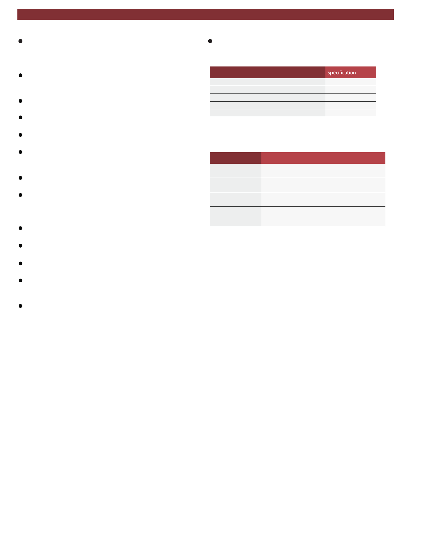
For safety reasons it is advisable to use a residual current
operated circuit breaker (rccb) with the following specifica-
tions:
Parameters
%01 ± CAV 011egatlov detaR
zH06/05ycneuqerf detaR
A01tnerruc detaR
Am03tnerruc gnippirt detaR
Chctiws gni
ppirT
2.5 Safety devices
Description Function
Pressure switch Switches the compressor off if the normal operat-
ing pressure is exceeded.
Safety valve The safety valve opens if the design pressure is ex-
ceeded.
Circuit breaker Interrupts the power supply if overcurrent is applied
to the AC438.
Vents The AC438 is provided with vents in the bottom
of the housing to ensure the exchange of air even
when switched off.
Important notes | AC438 | 7 | en
1901016-85

3. Product description
3.1 Application
AC438 is suitable for vehicles with a conventional engine as
well as for hybrid and electric vehicles. AC438 features all the
functions required for vehicle A/C service.
The following functions can be implemented:
Refrigerant recovery and recharging.
Vacuum generation.
Flushing.
m The AC438 can only be operated with R134a. The
AC438 is not to be used for service work on vehicles
with air conditioning systems employing refrigerants other
than R134a, as this will cause damage. Prior to A/C service
check the type of refrigerant used in the vehicle air condition-
ing system.
3.2 Scope of delivery
Description
Service hose (high pressure)
Service hose (low pressure)
Quick-release coupling (high pressure)
Quick-release coupling (low pressure)
Used oil bottle
Original instructions
Adapter (external bottle) - US Acme 1/2
Calibration check weight
en | 8 | AC438 | Product description
1901016-85
Product description | AC438 | 9 | en
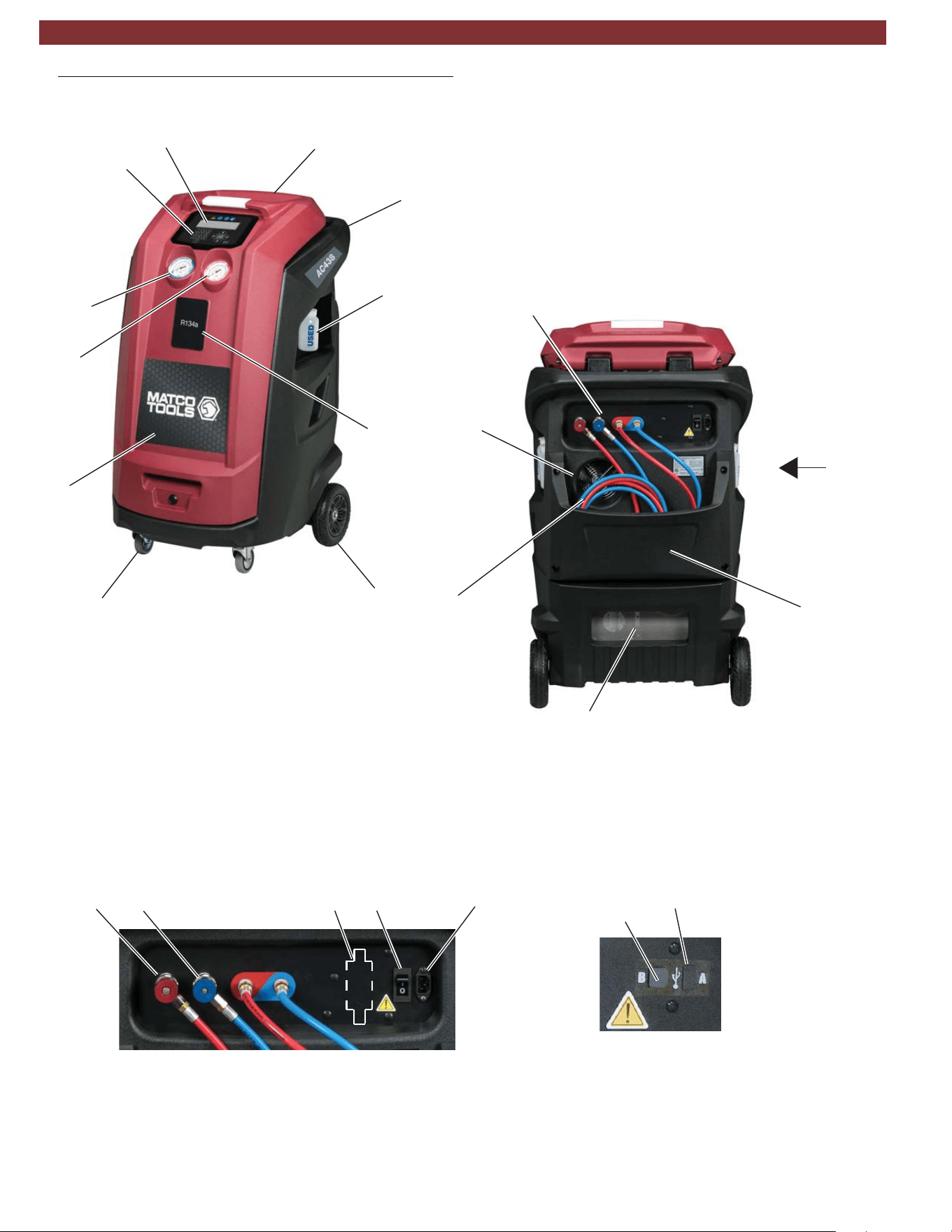
3.3 Description of unit
1
2
3
4
5
6
7
8
9
10
11
Fig. 1: Front Left View
Fig. 2: Rear View
View A: USB ports
Fig. 3: Rear Connection View
1
2
3
4
1
32154
2
1. USB Type B (device port to PC)
2. USB Type A (USB memory stick port)
Figure 3
View A
(see below)
(see below)
1. Rear Handle
2. Tool Tray
3. LCD Display
4. Keypad
5. Low Pressure Gauge
6. High Pressure Gauge
7. Front Cover
8. Locking Caster
9. Rear Wheel
10. Used Oil Bottle
11. Printer Optional
1. Service Hoses
2. Fan
3. Vent
4. Hose Storage
1. High Side Parking Coupler
2. Low Side Parking Coupler
3. Power Switch with circuit breaker
4. Power Cord Connector
5. Identifier (optional)
1901016-85
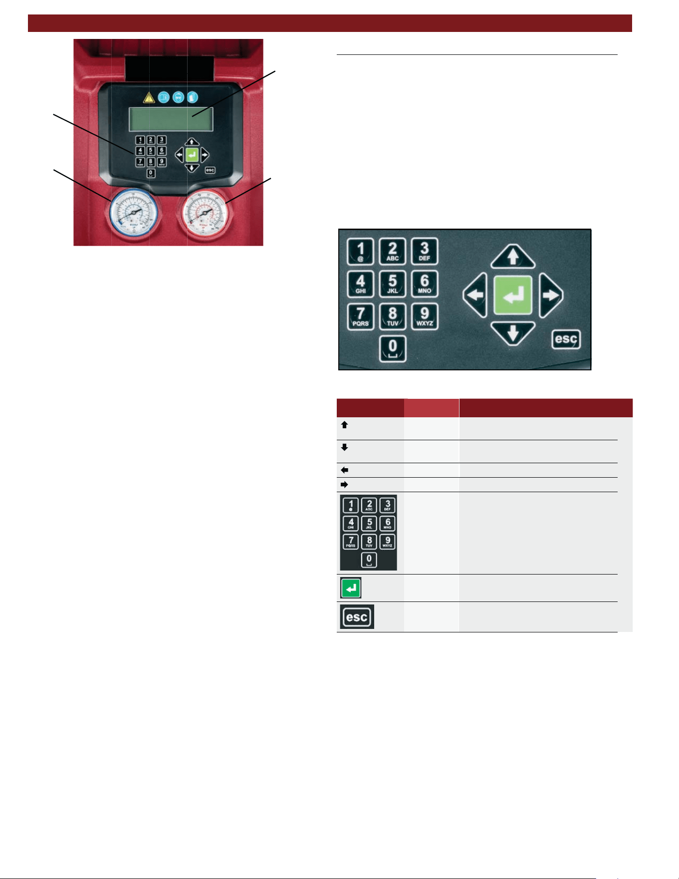
1
2
3
4
Fig. 4: Display and operating unit
High-pressure gauge
Low-pressure gauge
LCD display
Keypad
The pressure gauges (Fig. 4, Pos. 1, 2) of the display and operat
-
ing unit are used to monitor the pressure during the individual
vehicle A/C service phases. The status of the various service
phases during maintenance is displayed on the LCD screen
(Fig. 4, Pos. 3).
The menu selection and necessary entries are made by way of
the keypad (Fig. 4, Pos. 4) integrated in the panel.
If a situation arises where the unit software requires updated,
MATCO has a USB stick available for updating the AC438
software. The USB stick can be inserted in the USB socket to
perform updating of the firmware/software.
3.4 User interface
3.4.1
Selection and function keys
All settings, controls and service functions are available in the
pages shown on the LCD display. Data entry and moving of
the cursor is controlled by the keypad. The LCD displays the
service equipment's status, the progress of A/C system serv-
ice and any alarms/error messages. When a button is pressed,
a beep sounds.
The following buttons are available:
Fig. 5: AC438 keypad
Keys Name Function
Up
To move up in the menu options or
data field
Down
To move down in the menu options or
data field
Left Arrow to decrease data value
Right Arrow to increase data value
Keypad/
Input Keys
To enter a text with numbers and/or char-
acters. To enter letters/symbols, push
key multiple times to select one of the let-
ters available under that key - just as the
keyboard of a phone to compose SMS.
Enter To confirm and go ahead
Escape To interrupt the operation in progress
3.4.2 Input keys
The input keys can be used to enter letters, numbers and special
characters in the input boxes. If a key is pressed several times
in succession in the input box, all the characters which can be
used for this are displayed.
2
4
3
1
en | 10 | AC438 | Product description
1901016-85
3.4.3 Display screen
When unit loads, the total refrigerant weight screen will be dis -
played. Press to go to main menu as displayed in Fig. 6.
To select a function in the menu, press or
to scroll to the
name of the desired function. The text name will blink once high -
lighted, then press the green ENTER key to select.
The menu moves up/down one line for every push of the
or
key.
A down arrow will appear in the lower right corner of the screen
as an indication that more menu option are available below
what is displayed on the current screen.
Fig. 6: Main menu screen
If you need to enter free text, the numerical keypad can be used.
The keyboard works like a keyboard of a phone to compose
SMS: press some times to select one of the letters available
under that key.
3.4.4 Main menu options
The main menu of the graphical user interface allows user to
select the following functions:
Automatic cycles
Manual cycles
Setup
Maintenance
Service
Each of the menu options will be described in detail later in
the manual.
3.5 Unit features
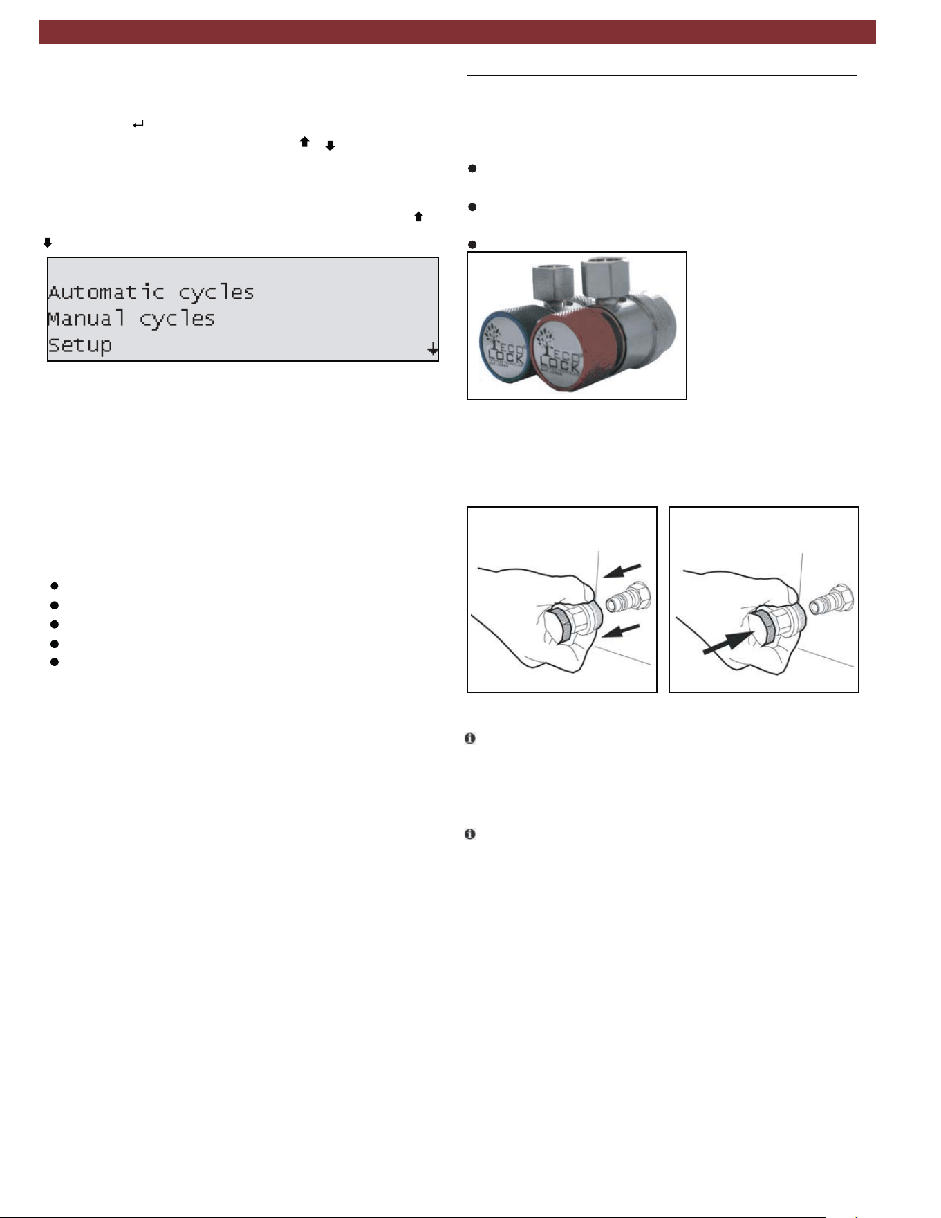
3.5.1
EcoLOCK
®
quick couplers (optional)
EcoLOCK
®
is the intelligent coupler, that with the suitable auto-
mated procedure in the software enables to:
reduce the amount of non-condensible gases formed inside
the cylinder.
avoid the refrigerant (loss) dispersion in the air during the
disconnection of the couplers (puff-effect).
check possible Schrader valve leaks before disconnection.
Fig. 7: EcoLOCK
®
couplers
To connect the coupling, position the coupling on the parking
coupler, pull back the knurled section of the coupling element
and press carefully onto the connection (Fig. 8).
Fig. 8: Fastening quick release coupling
t The service quick-release couplings are connected to the
service connections of the vehicle air conditioning system
during A/C service. When not in use, the service quick-release
couplings can be connected to the parking/flush couplers.
t To remove the service quick-release couplings from the park-
ing/flush coupler, press the coupling slightly towards the con-
nection and carefully pull the knurled section back to unfasten
it from the coupler.
3.5.2 Locking caster brakes
Rolling of the AC438 can be prevented by locking the caster
brakes (Fig. 1, Pos. 8) at the front wheels.
3.5.3 Power supply cable and switch
The power supply cable is connected to the main power input.
When not in operation, the power supply cable can be discon-
nected and hung on the handle. The AC438 is switched on
by toggling the rocker switch to the on position.
AC438
Product description | AC438 | 11 | en
1901016-85
3.6 Functional description
The refrigerant recovered from the air conditioning system passes
through the combo filter to remove suspended particles and
moisture.
The purpose of the vacuum pump is to generate a vacuum in
the air conditioning system which removes excess moisture and
to detect possible leaks in the vehicle air conditioning system.
Used oil is separated from the recovered vehicle refrigerant and
drained into the used oil bottle.
The vehicle air conditioning system is partly filled with
UV dye to facilitate the detection of leaks in the event of
damage to the vehicle air conditioning system.
The refrigerant in the internal refrigerant bottle is used for filling
the vehicle air conditioning system.
The purging unit for the non-condensable gases, consisting of
a temperature sensor, pressure sensor, coil and orifice, always
takes effect when the internal refrigerant bottle pressure is
higher than the saturation pressure.
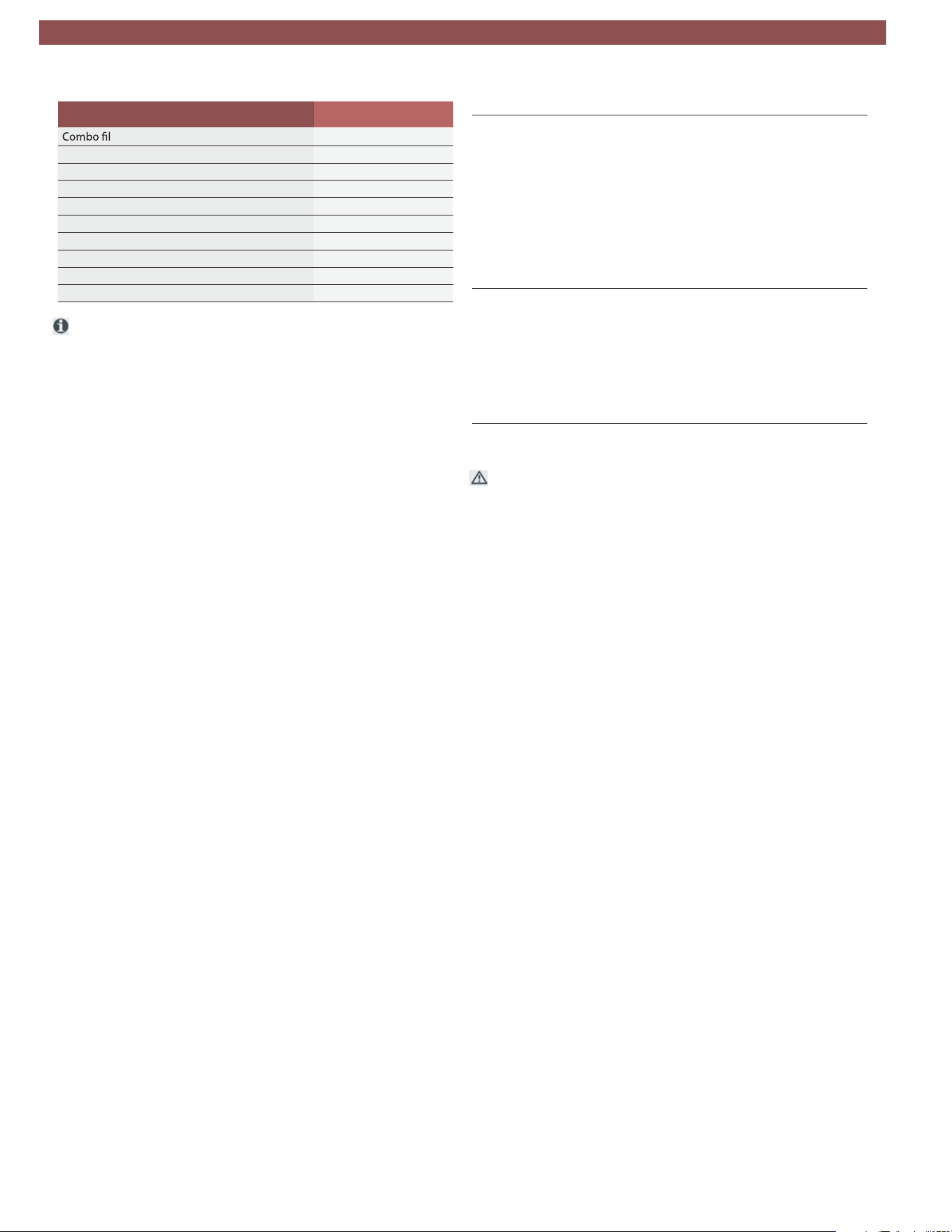
4. Technical features
Description Specification
R134a tank capacity 12L
Service pressure 400PSI
Maximum content 22lbs
Method to weigh gas content Load cell
Recovered oil container 250ml
Vacuum pump 2CFM dual stage
Vacuum pump oil quantity 250ml
Compressor capacity 0.87cu in/14cc
Dryer filter
a431R derevocer fo gk57
Non-condensible gas purge Automatic via solenoid valve
HP and LP taps Automatic
stod 46x042 NTSF emorhconom DCLyalpsiD
enarbmeMdapyeK
Software updating USB type A or USB type B direct con-
nect to PC
Printer (optional) Thermal, 24 columns
All functions Automatic and manual
Recycling mode Single or multipass
Memory for customized cycles 100 records
sevlav dionelos detargetni htiWgnihsulF
System pressure diagnostics Manual and automatic
Dr
ter replacement alarm Active
Vacuum pump oil replacement
alarm
Active
Full/empty tank check alarm Active
Full oil container check alarm Visual
Empty oil container alarm Visual
Dimension HxWxD 119 x 74 x 74 cm
Dry weight 98kg
Power supply frequency 60Hz
esahp 1 ,CAV021egatloV
Total max load 7.5A
Overcurrent protection 12A (circuit breaker)
Operating temperature 50-122°F
)gnisnednoc non( HR%09-01ytidimuH
Storage temperature and hu-
midity
-13 to 50°F
10-90%RH (non condensing)
Max operating altitude 6562ft
Pollution degree 2
Water degree 0
Certifications SAE J2788
UL1963
CAN/CSA STD C22.2 NO. 120-M91
en | 12 | AC438 | Technical features
1901016-85
5. Equipment installation
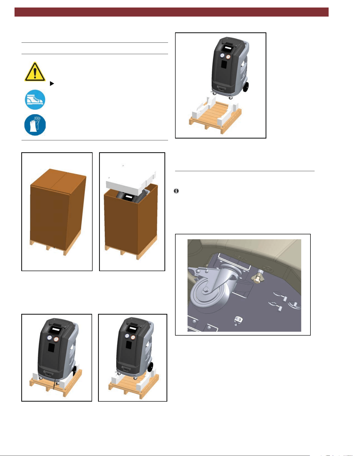
5.1 Unpacking AC438
Warning – Risk of personal injury!
Incorrect handling could cause equipment to
overturn.
The manufacturer disclaims all responsibility
for damage to objects and/or persons resulting
from the equipment being wrongly removed
from the pallet, or if the operation is performed
by unsuitable personnel, with improper means/
protections and without complying with the
existing laws on manual handling of loads and
with the operations described in this manual.
1. Cut the straps and remove the carton (Fig. 9)
Fig. 9: Removing carton
2. Cut straps securing unit to pallet.
3. With 2 people, lift both front wheels by levering with the
handle so unit is setting on the rear wheels (Fig. 10).
Fig. 10: Tilting unit backwards
4. Slowly lower the unit from pallet by means of the rear
wheels (Fig. 11).
Fig. 11: Lowering unit from the pallet
5. Keep the pallet, carton, and scratch protection film for
use in case of a need to return unit.
5.2 Load cell screw release
t
The AC438 is shipped from the manufacturing facil-
ity with the load cell blocked to prevent damage during
shipment.
1. On the underside of the unit (towards the front) there is a
screw with a wingnut threaded into the base. Loosen the
wingnut and unscrew bolt (Fig. 12).
Fig. 12: Removing load cell retention bolt
Product description | AC438 | 13 | en
1901016-85
6. Commissioning
t All the operations described in Section 5 and 6 must be
performed prior to first A/C service.
6.1 Connections and positioning
m
The AC438 is designed for 110V, 50/60Hz. Follow the
information on the AC438 rating plate.
1. Set the AC438 on a flat, vibration-proof surface.
2. Actuate the caster brake to stop the AC438 from rolling.
3. Connect the power supply cable to the power supply.
4. Switch on the main switch.
m The unit must be positioned on a stable, horizontal surface to
ensure correct operation. Unit must be in an area with proper
ventilation and at least 10cm from any potential obstacle to
its internal ventilation.
m Keep unit out of rain and excessive humidity as moisture
could cause irreparable damage.
m Prevent exposure to direct sunlight and excessive dust.
m Unit must be properly grounded with the power plug ground
pin. Failure to ground unit can cause damage and constitutes
a risk of fatal injury or shock to the operator.
t Do not unplug any internal electrical connections and only
have internal components opened and repaired by trained
customer service personnel.
t Contact customer service in the event of any transportation
damage (e.g. oil leakage).
t Leave quick couplings closed when unit is not in use and at
end of vehicle service operations.
6.2 First start-up verification
Check the service hoses for damage.
Firmly connect the service quick-release cou-
plings to the service hoses.
Wear protective goggles.
Wear protective gloves.
Execute the following actions in sequential order by following the
procedure as shown on the display:
— Gas weight check (vacuums entire refrigerant circuit to
ensure no contaminants are in system prior to filling
— First internal cylinder fill
o It is possible to interrupt the initial check and print a report
in which the status of the check is reported (if printer option
was purchased).
t Equipment cannot operate in automatic mode until all the
steps of initial check are completed.
1. Set the internal cylinder fill
to desired quantity (min. 3kg).
2. Follow on-screen instructions.
3. Make sure hoses are disconnected from any external source
at this time.
4. Start the procedure that initially creates vacuum in the internal
refrigerant circuit (approximately 15 minute process).
5. Once message is displayed, the unit can be connected to the
external cylinder and the valves opened.
6. Just before the targeted refrigerant amount is reached, unit
will pause and prompt user to close external refrigerant tank
connection.
7. Once this is done, the unit will continue to recover the refriger-
ant from the hoses and end once this is completed. The total
amount recovered will then be displayed.
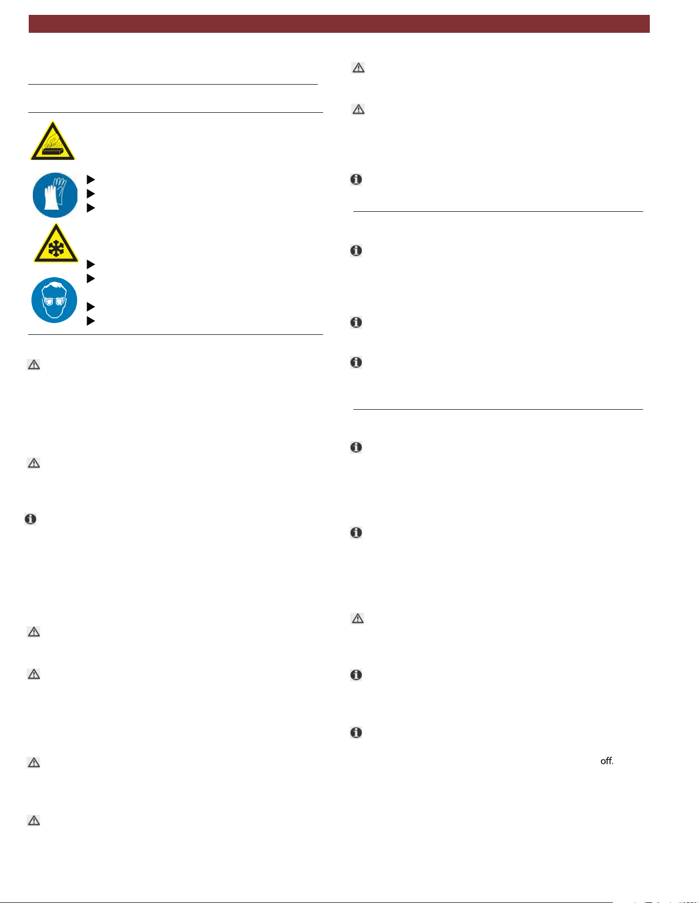
t Check the type of source tank, two types are available:
—
Connect to the the liquid valve and keep tank in the upright
position to transfer refrigerant.
— Refrigerant cylinder without plunger (single valve):
Refrigerant cylinder with plunger (typically 2 valves):
Connect to the available valve and invert tank to transfer
refrigerant.
Fig. 13: Virgin refrigerant cylinder tank types
t The LP (blue) gauge indicates the pressure inside the external
cylinder.
Refrigerant causes frostbite on the skin
Warning - Risk of frostbite from escaping
refrigerant
en | 14 | AC438 | Commisioning
1901016-85

7. Setup
7.1 AC438
t
From the SETUP menu, it is possible to enable/disable and
set certain parameters prior to performing A/C system service.
To access SETUP from the main menu, press
to highlight
SETUP and then press .
Parameter Description
EcoLOCK Enable/disable EcoLOCK functionality
Recharge mode Select Quick mode or Zero tolerance recharge method
Pressure check Enable/disable the pressure check
Multipass Enable/disable the Multipass function
Report saving
mode
Adjust what reports are saved during A/C service
Unit of measure Modify the unit of measure for pressure and weight
Clock adjustment Modify the date and time
Language Modify the language displayed on the LCD display
Startup screen Select if upon power-up the unit displays the
database page or main menu screen
Default setup Restore unit default settings
t If while adjusting settings user does not want to apply any
change made, just press ESC from the parameter screen to
discard the change made to that specific area.
7.1.1 Ecolock (optional)
1. From the SETUP menu, press until EcoLOCK is high-
lighted and press
2. Adjust whether the EcoLOCK function is enabled or disabled
by pressing
3. Press to highlight SAVE, then press to save selection.
7.1.2 Recharge mode
t
For a more detailed description of the 2 charge modes, see
Section 8.3.
1. From the SETUP menu, press
until RECHARGE MODE
is highlighted and press
2. Adjust whether the Recharge mode is in Quick mode or
Zero tolerance by pressing . (If Zero Tolerance mode is
selected, press
to highlight the pressure and use to
adjust the value.)
3. Press to highlight SAVE, then press to save selection.
7.1.3 Pressure check
1. From the SETUP menu, press until PRESSURE CHECK
is highlighted and press
.
2. Adjust whether the Pressure check function is enabled or
disabled by pressing
3. Press to highlight SAVE, then press to save selection.
7.1.4 Multipass
t Multipass is a function user can enable that will run when
unit is powered up and in an idle state. This function circu-
lates the refrigerant from the internal cylinder through the
filters to ensure optimal purity.
1. From the SETUP menu, press until
MULTIPASS
is high-
lighted and press
.
2. Adjust whether the Multipass function is enabled or disabled.
3. Press
to highlight SAVE, then press to save selection.
7.1.5 Report saving mode
1. From the SETUP menu, press until REPORT SAVING
MODE is highlighted and press
2. Adjust whether all cycle reports, automatic cycles only or no
reports are saved by pressing
3. Press to highlight SAVE, then press to save selection.
7.1.6 Unit of measure
1. From the SETUP menu, press until UNIT OF MEASURE
is highlighted and press
2. Use
to select if Pressure or Gas units are to be adjust-
ed, then press
.
3. Adjust the units by pressing
4. Press to highlight SAVE, then press to save selection.
5. If other units are to be adjusted, press
to select
other
parameter or press
to highlight SAVE , then press to save
any changes.
Setup | AC438 | 15 | en
1901016-85

7.1.7 Clock adjustment
1. From the SETUP menu, press until CLOCK ADJUSTMENT
is highlighted and press
.
2. Highlight value that needs to be adjusted by pressing
.
3. Adjust value by pressing
4. Press until SAVE is highlighted, then press to store entries
and return to Setup menu.
t Date is displayed as follows: DD/MM/YYYY.
7.1.8 Setting language
1. From the SETUP menu, press until
LANGUAGE
is high-
lighted and press
2. Adjust the language by pressing
3. Press to highlight SAVE , then press to save selection.
4. Unit will restart upon saving the language selection.
m If a language is selected that is not understood, simply switch
unit
depress enter key ( ) , and turn unit back on (keeping
depressed). This will automatically load the language selec-
tion screen.
7.1.9 Startup screen
1. From the SETUP menu, press until STARTUP SCREEN is
highlighted and press
.
2. Adjust whether the unit startup screen is the main menu or if
unit goes directly to the database using
.
3. Press to highlight SAVE, then press to save selection.
7.1.10 Default setup
1. From the SETUP menu, press until DEFAULT SETUPis
highlighted and press
.
2. Press
to reset all settings to the factory settings.
en |16 | AC438 | Setup
1901016-85
8. A/C service preparation
8.1 Preliminary preparation
Warning - risk of burns from hot engine
components
Warning - risk of frostbite from escaping
refrigerant
Refrigerant causes frostbite on the skin.
Contact with hot engine components will
cause severe burns.
Allow the engine to cool down.
Wear protective goggles.
Wear protective gloves.
Check the service hoses for damage.
Firmly connect the service quick-release cou-
plings to the service hoses.
Wear protective goggles.
Wear protective gloves.
Perform the following preparatory work prior to vehicle A/C service:
m Service hoses must be contructed of the proper materials and
have the lengths as supplied with the unit. Hoses must have
shutoff devices (quick-release couplers) at the connection point
to the A/C to minimize the introduction of air into the AC438
and to minimize the amount of refrigerant released while
disconnecting the hoses.
m Inspect hoses for signs of damage prior to performing A/C
service. Use of damaged hoses will result in the loss of refriger-
ant and the possibility of refrigerant contamination.
t Follow the vehicle manufacturer's recommendations for A/C
service on vehicles with a low-pressure connection only.
1. Set the Ac438 on a flat, vibration-proof surface.
2. Actuate the caster brake to stop the unit from rolling.
3. Connect the power supply cable to the power supply.
4. Switch on the main switch.
t Follow the manufacturer's instructions for the corresponding
vehicle before performing A/C service.
t A/C service operations (especially recovery) should be per-
formed after the vehicle has been run for a period of time to
allow engine heat to raise system pressure. This allows for the
maximum refrigerant recovery amount to occur. If system is
excessively hot, the recharge phase could be adversely
effected.
m The AC438 is only to be operated with R134a refrigerant.
Check which refrigerant is used for the vehicle before perform-
ing A/C service.
m The AC438 cannot be used for air conditioning systems
repaired using a chemical sealant. Non compliance will void the
warranty.
m Never attempt to close the valves of the internal refrigerant
bottle while the AC438 is in operation.
m Only new lubricant, as specified by the system manufacturer,
shall be installed in the MAC system. Lubricant removed from the
system and/or equipment shall be disposed of in accordance with
the applicable federal, state, and local procedures and regulations.
t The service parameters (recharge quantity) can be found in the
owner's manual or the vehicle repair manual.
8.2
Non-condensible gas discharge
t
If the AC438 detects non-condensible gases in the internal
cylinder, the unit will prompt technician to allow unit to run an
air purge. This prompt will occur every time unit is powered on
(if unit has been powered off for at leats 1 hour)
t The process will perform automatically upon the start of a charge
procedure if non-condensibles are detected.
t Air purge is a necessary process to ensure ideal working parame-
ters for the AC438. Presense of non-copndensible gases will
increase tank pressure and reduce efficiency of recharge cycles.
8.3 Charge modes
t
The AC438 has 2 different refrigerant charge methods. If
charge does not complete using Quick mode, the Zero tolerance
method automatically commences.
8.3.1 Quick mode
t In Quick mode, the AC438 injects refrigerant through the
HP port. The refrigerant remains in the hoses at the end of the
cycle and is then recovered during a hose clearing process.
8.3.2 Zero tolerance mode
m
While the Zero tolerance mode is slightly longer in time, it
provides a more accurate recharge and guarantees a
successful charge.
t In Zero tolerance mode, the AC438 will by default charge
throught the HP (red) hose, then refrigerant that remains in
in the hoses is pulled into the vehicle's A/C system through
the LP (blue) hose.
t In the instance where only a LP coupling is available for A/C serv-
ice, the AC438 will charge the system with 50% of the total
charge amount with the vehicle A/C compresor The unit then
waits 10 minutes to allow the liquid refrigerant to evaporate to pre-
vent damage to the compressor. The vehicle must be started and
the A/C system turned on. The AC438 will continue to charge
refrigerant whenever the LP hose pressure is less than 3 bar.
A/C service preparation | AC438 | 17 | en
1901016-85
9. A/C system service
9.1 Automatic cycles
t
Access to automatic cycles is available through the main
menu by selecting “AUTOMATIC CYCLES”.
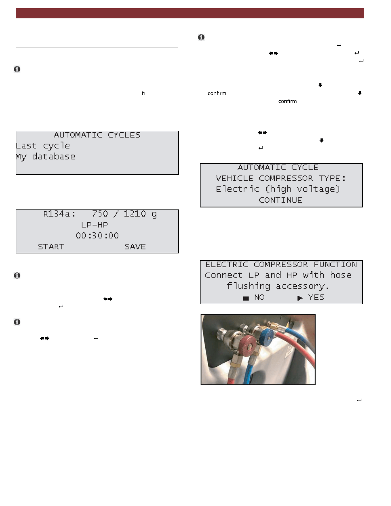
1. To begin Automatic cycle setup, user must
rst select whether
they would like to load the parameters used during the last
A/C service or select My database to load custom
parameters previously saved by the technician.
Fig. 14: Automatic cycle selection
2. After the selection is made, a screen will appear showing
the data for the process (Fig. 15).
Fig. 15: Parameter adjustment
t The amount of refrigerant to be charged into the system and
the amount of refrigerant available in the internal cylinder are
listed in the top row of the screen. To adjust the charge amount,
highlight the value and press
to adjust the value higher or
lower. Press to save selection and move to next parameter.
t The second row displays the hose selection for the service.
To adjust the hose selection, highlight the current value and
press
to adjust. Press to save selection and move to
next parameter. The following options are available:
— HP only
— LP only
— HP and LP
— HP(LP) - Injection through HP hose on the system low
pressure side (Specific for some Renault models).
t Third row of information displays the vacuum time. To adjust
the vacuum time, highlight the value and press
. Adjust
vacuum time by using
to change value then press .
Adjust vacuum test time using the same method. Press
to
save selection and move to next parameter.
3. After the parameters are adjusted, press
to select and
START to begin the Automatic cycle. (Or press
a
second time to select and
SAVE to save the cycle
information to My Database.)
4. A screen will
then
appear to adjust the vehicle's compressor
type (Fig. 16). Use
to change between ELECTRIC and
MECHANICAL compressor type, press to select CON-
TINUE, then press .
Fig. 16: Compressor type selection
5. If the selected type is Electric (high voltage), a special flushing
procedure will be executed to clear any potential oil residue in
hoses from previous services. The screen in Fig. 17 will appear
and the hoses should be connected as illustrated in Fig. 18.
Fig. 17: Electric compressor function
Fig. 18: Flush adaptor connection
6. After the connection is made, confirmYES (by pressing ) to
proceed and follow instructions displayed on screen.
en | 18 | AC438 | A/C system service
1901016-85
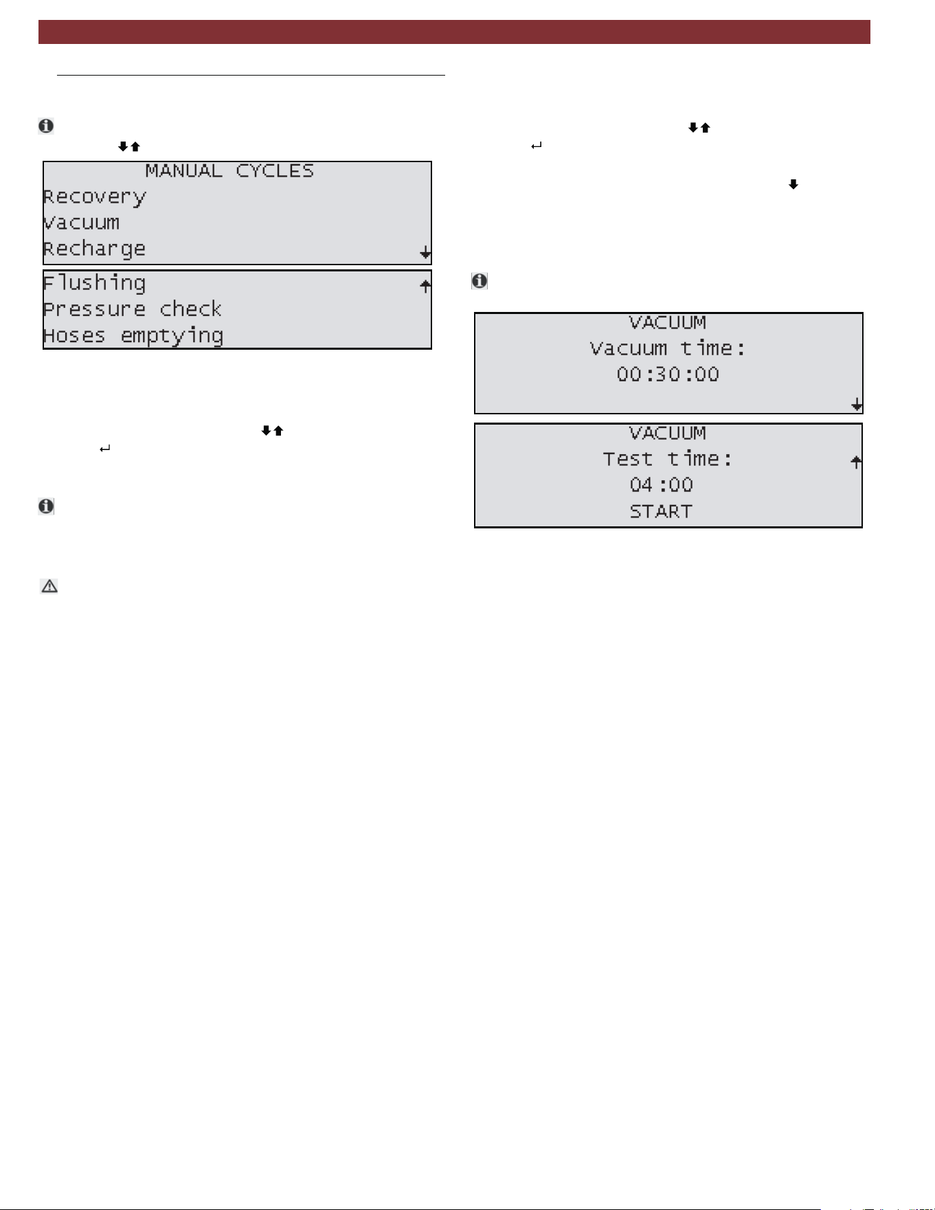
9.2 Manual cycles
t
Access to manual cycles is available through the main menu
by using to select "
Fig. 19: Manual mode screen options
9.2.1 Recovery process
1. In the manual cycle menu, use to select Recovery and
press
.
2. Follow on screen instructions to begin recovery process.
t If no pressure is detected in the system, this function will not
start. Technician should ensure couplers are open. If the sys-
tem is empty, operator must exit and select a vacuum
process.
m There is potential for unit to display an error during this
service for high internal pressure. This can occur due to high
operating temperatures or hot refrigerant gasses entering the
AC438.
9.2.2 Vacuum process
1. In the manual cycle menu use to select Vacuum and
press
.
2. The unit will display a screen for technician to enter the length
of vacuum time and vacuum test time. (press
to display
Vacuum test time screen).
3. Connect HP/LP coupler(s) to the vehicle A/C system, open
the couplers and select START.
Be sure recovery has been performed prior to running a
Vacuum cycle.
Fig. 20: Vacuum setup screens
A/C system service | AC438 | 19 | en
1901016-85

9.2.3 Recharge
1. In the manual cycle menu use to select RECHARGE
and press
2. Adjust the value on the screen to match what the vehicle’s
A/C system requires by pressing . Note: If the value
entered is higher than what is available in the internal
cylinder, the procedure will not begin.
3.
Connect couplers to the vehicle fittings and follow
on-screen instructions.
Install flushing kit as described in the instructions
included with kit.
Follow on-screen instructions.
The system flush process charges liquid refrigerant
through the connected components and filters
impurities through an additional filter.
After replacing components or parts of the A/C system,
it is advisable to carry out a system flush procedure.
Set whether service is to be performed on:
— HP only
— LP only
— HP & LP
— HP(LP) - Injection through HP hose on the system low
pressure side (Specific for some Renault
models).
4.
9.2.4 Flushing (with optional accessories)
t
t
1.
2.
9.2.5 Pressure check
t
This process is used to check the pressure inside the
vehicle’s A/C system using the AC438.
1.
Connect HP & LP couplers to the vehicle A/C system.
Follow on-screen instructions - start vehicle and turn on
the A/C system.
2.
3. Set temperature at coldest setting.
4. Set fan speed at maximum level and close all vents except
the central one and set air distribution to that vent.
5. Keep engine at high idle speed (approx. 2000RPM) for at least
2 minutes.
6. Check pressure values in 3 - 5 minutes.
7. Once these steps are complete, select Pressure Check
function.
8. At the end, check that both values on the HP and LP
To clear pressure from inside unit hoses, in the manual cycle
menu use to select hose emptying and press
Pressure values change considerably when ambient
temperature changes. Keep this in mind when checking
pressure values.
gauges fall between the values shown on the display..
m
9.2.6
Hose emptying
1.
2.
.
Allow procedure to run to completion.
en | 20 | AC438 | A/C system service
1901016-85
10. Maintenance
t Please contact an authorized technical service center for
purchasing factory replacement parts.
10.1 Maintenance interval
doirePnoitpircseD
System leak test As required
Vacuum pump oil replacement and
system leak test
After 1000 hours of service
Combo filter replacement and system
leak test
After 75kg of refrigerant
processed
m Make sure AC438 is disconnected from power before
removing plastic housing.
m Never perform any maintenance work which is not
expressly recommended in this Section.
m Contact customer service if components have to be
replaced other than in the course of maintenance work.
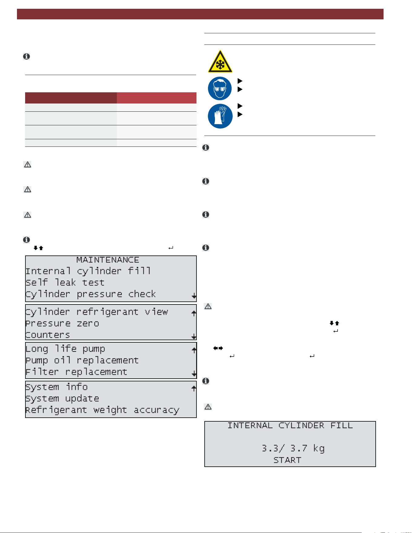
t To access MAINTENANCE from the main menu, press
highlight MAINTENANCE and then press
.
Fig. 21: Maintenance screens
10.2 Filling internal refrigerant cylinder
Warning - Risk of frostbite from escaping
refrigerant
Refrigerant causes severe frostbite on the skin.
Check the service hoses for damage.
Firmly connect the service quick-release cou-
plings to the service hoses.
Wear protective goggles.
Wear protective gloves.
t Before the AC438 can be used, the internal refrigerant
cylinder must be filled with liquid refrigerant. Use only R134a
refrigerant.
t The refrigerant can be obtained from your gas supplier. It can
be stored normally and transported in bottles with connec-
tion fittings.
t To ensure a reliable procedure, it is advisable to use the
optimum quantity of refrigerant. The optimum quantity of
refrigerant for the AC438 is 4kg – 10.0kg.
t An inadequate quantity may make efficient filling of the vehicle
air conditioning system impossible. Also, if there is an insuf-
ficient quantity, the AC438 may not be able to operate
efficiently. In the event ofan excessive quantity, there may not
be sufficient space for the refrigerant recovered from the
vehicle air conditioning system.
m Do not open coupler until unit prompts technician to open.
1. From the MAINTENANCE INTERNAL menu, press until
CYLINDER FILL is highlighted and press
.
2. To adjust the charge amount, highlight the value and press
to adjust the value higher or lower.
3. Press to accept value and press again to begin process.
4. Follow the menu prompting.
t The current pressure inside the external refrigerant bottle is
indicated on the low-pressure gauge.
m Do not interrupt the automatic filling prior to automatic
termination by the AC438.
Fig. 22: Internal cylinder fill setup screen
Maintenance | AC438 | 21 | en
1901016-85
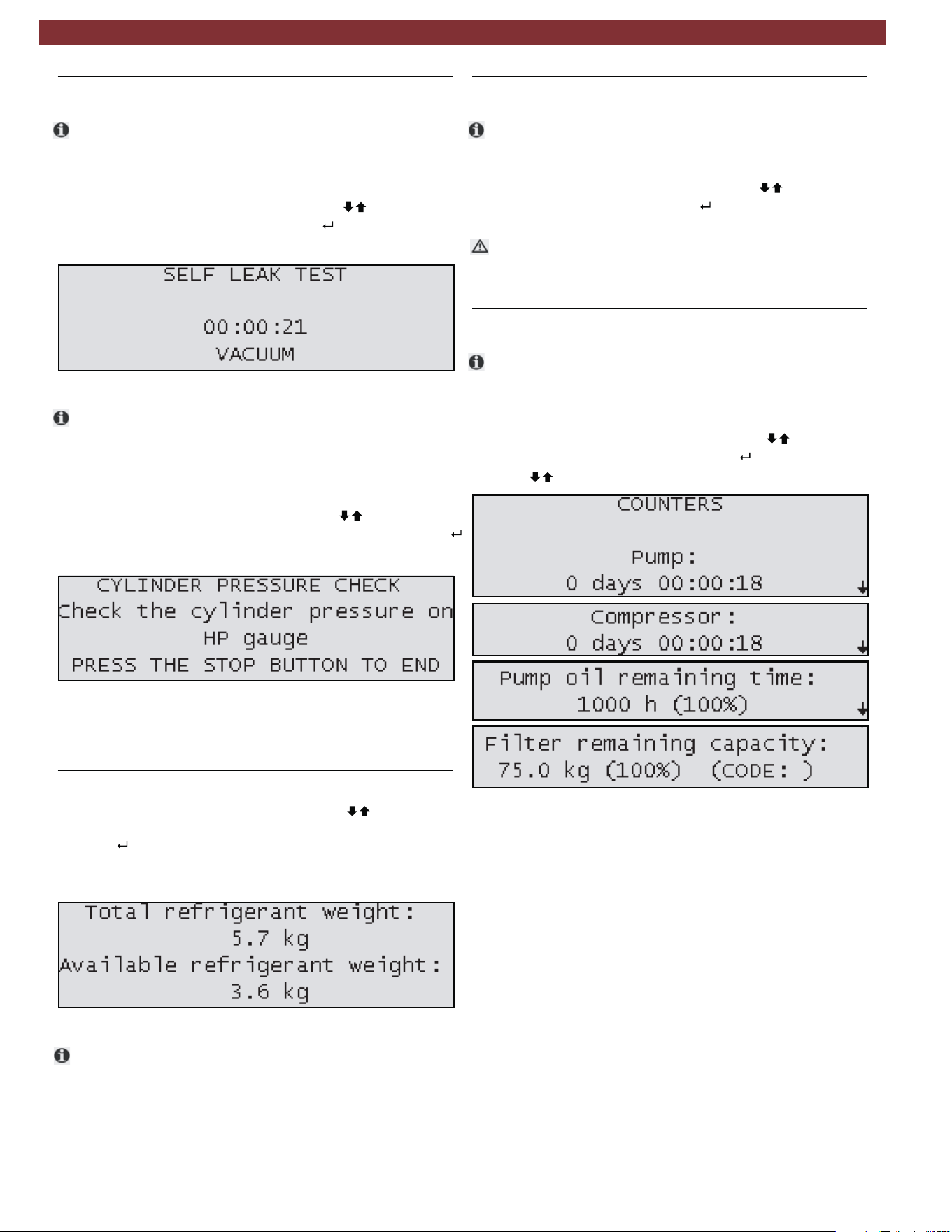
10.3 Self leak test
t
This test is designed to check the internal AC438
circuit for any leaks.
To perform Self leak test:
1. From the MAINTENANCE menu, press
until SELF
LEAK TEST is highlighted and press .
2. Allow unit to perform test to completion.
Fig. 23: Self leak test screen
t If a test fails, check charge hoses and quick couplers for
leak first. If repair is possible, fix the leak and repeat test.
10.4 Cylinder pressure check
1. From the MAINTENANCE menu, press until
CYLINDER PRESSURE CHECK is highlighted and press .
2. Screen will display message shown in Fig. 24.
Fig. 24: Cylinder pressure check screen
3. Press stop once HP (red) gauge displays pressure inside
tank.
10.5 Cylinder refrigerant view
1. From the MAINTENANCE menu, press until
CYLINDER REFRIGERANT VIEW is highlighted and
.
2. Screen will display the Total refrigerant weight and the
Available refrigerant weight.
Fig. 25: Refrigerant weight screen
t Available refrigerant weight is 2kg less than total contents of
cylinder. 2kg is the minimum quantity that should be left in
an operating AC438.
10.6 Pressure zero
t
This function allows technician to determine and store the
atmospheric pressure value.
1. From the MAINTENANCE menu, press until PRESSURE
ZERO is highlighted and press
.
m This procedure should be performed every time the
AC438 is moved from one location to another that has a
different altitude.
10.7 Counters
t
These screens will display the vacuum pump and compres-
sor hours of life and the remaining time before vacuum
pump oil and the filter dryer need replacement.
1. From the MAINTENANCE menu, press
until
COUNTERS
is highlighted and press
.
2. Press to display all counters.
Fig. 26: Counters
press
en | 22 | AC438 | Maintenance
1901016-85
10.8 Long life pump test
t
1.
2.
3. The process will run approximately 1 hour.
At the end of procedure, vacuum pump performance check
is displayed on the display.
t
4.
t
t
Fig. 27: Long life pump screen
10.9 Vacuum pump oil change
t
Fig. 28: Changing vacuum pump oil
Fig. 29: Reset vacuum pump oil life
t
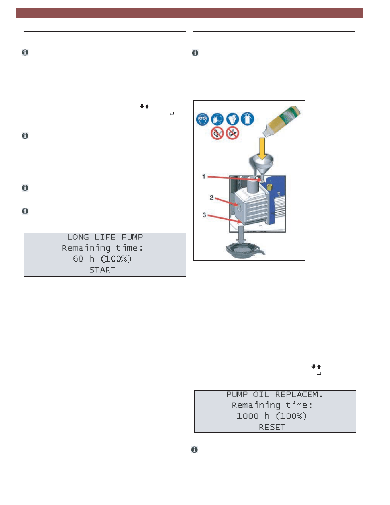
The Long Life Pump function equipped on the AC438
enables the unit to optimize the vacuum pump oil use
and avoid the need to replace after every 60 hours of
operation.
From the MAINTENANCE menu, press until
LONG LIFE PUMP TEST is highlighted and press .
During this process, the vacuum pump oil is auto-
matically purified from the gaseous residues absorbed
by the oil during the vacuuming of vehicle A/C systems.
After the first 60 hours of vacuum pump operation,
check the vacuum pump oil level and top-off if
necessary.
If the result of the Long Life Pump test is negative, the oil
must be changed.
If the results pass, the pump oil remaining time will change
to 1000 hours. After 1000 hours of runtime, the oil must
be changed.
After 60 hours of runtime (or 1000 hours if the Long Life
Pump test is completed successfully), the vacuum pump oil
must be replaced.
1. Disconnect AC438 from power.
2. Unlock front latch and carefully lift cover.
1 OIl filling plug
2 Oil inspection window
3 Lower drain plug
3. Place a bowl under the vacuum pump oil hole. Remove
the upper filling plug and the lower drain plug to allow the oil
to drain from the unit.
4. Once the pump has been emptied, reinstall the lower drain plug.
5. Fill the pump with new oil through the upper fill port using a
funnel if needed. Fill until the oil appears halfway up the oil level
inspection window.
6. Once the pump has been filled, reinstall the upper fill plug.
7. Carefully close front cover and secure latch.
8. Connect to power and turn on.
9. From the MAINTENANCE menu, press until PUMP OIL
REPLACEMENT is highlighted and press . Press the RESET
key to set the counter.
The level and clearness of the vacuum pump oil can be checked
by removing the rubber plug located on the front-left side of
the unit.
Maintenance | AC438 | 23 | en
1901016-85
10.10 Replace filter dryer
Warning - Risk of frostbite from escaping
refrigerant
Refrigerant causes severe frostbite on the
skin.
Check the service hoses for damage.
Firmly connect the service quick-release cou-
plings to the service hoses.
Wear protective goggles.
Wear protective gloves.
t Unit operation is disabled at the end of the filter service
life. Each filter is marked with a unique code. This code
must be entered when replacing the filter. It is not
possible to operate the AC438 if the same code is
re-used. It is advisable to keep a supply of filters in stock
to avoid downtimes due to the unit being disabled.
t The AC438 is disabled once 75kg of R134a refrigerant
has passed through the filter. A new filter must be
installed and its unique code entered in the AC438
before vehicle A/C service can be performed.
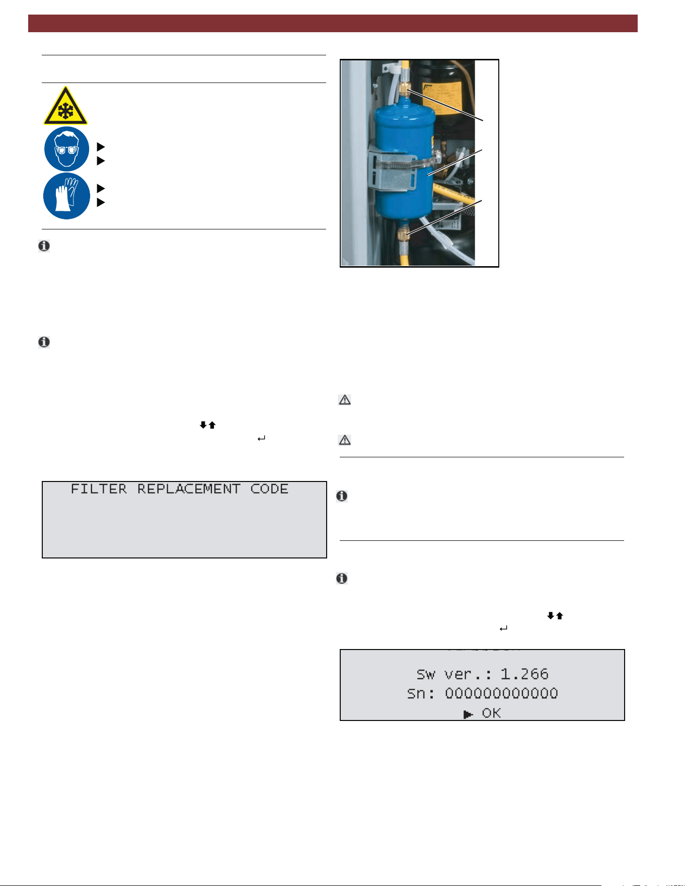
1. To begin the filter replacement process, from the
MAINTENANCE menu press until FILTER
REPLACEMENT is highlighted and press .
2. Insert the new filter code using the keypad.
3. Disconnect the HP and LP couplers and hoses and allow
the hose drain process to run to completion.
4. Disconnect the AC438 from power supply.
5. Turn front locking latch using a flathead screwdriver
and carefully open the front housing.
6. Unscrew the 2 connection nuts from the top and bottom
of the filterusing a 17mm open-ended wrench to prevent
the filter form spinning and a 24mm open-ended wrench
to loosen the nuts.
7. Remove the straps that hold the filter in place.
8. Install the new filter paying attention to the position of the
gaskets and ensure the arrow faces downward.
Fig. 30: Filter code entry
Fig. 31: Replacing filter
m
m
Never re-use an old filter.
10.11 Multipass
t
Run this procedure to circulate refrigerant within the AC438.
This allows the unit to further purify the refrigerant and remove
any dirt/other impurities.
10.12 System info
t
Fig. 32: System information screen
1
2
2
AC438
1 Filter dryer
2 Connection nuts
9. Tighten the 2 connection nuts to the filter.
10. Close the front housing and secure latch.
11. Connect unit to power and turn on.
12. Allow the unit to perform the automatic leak test
requested by the software when unit loads.
Take care not to damage any hoses or electrical connections
when changing the filter.
In the Info page, the software version and serial number
can be displayed.
1. From the MAINTENANCE menu, press until SYSTEM
INFO is highlighted and press .
en | 24 | AC438 | Maintenance
1901016-85
10.13 Software update
The firmware (software can be updated by way of a USB
stick.
1. Insert USB stick in USB port (Fig. B Pos. 2).
2
3. From the MAINTENANCE menu, press until
SOFTWARE UPDATE is highlighted and press .
4. A message will appear that the unit is loading an update.
5. The unit may load an updated language file and
configuration file while updating.
6. Once the unit is updated, the software version string
on the introduction screen during power up will change.
. Power on AC438.
10.14 Refrigerant weight accuracy test
t
m
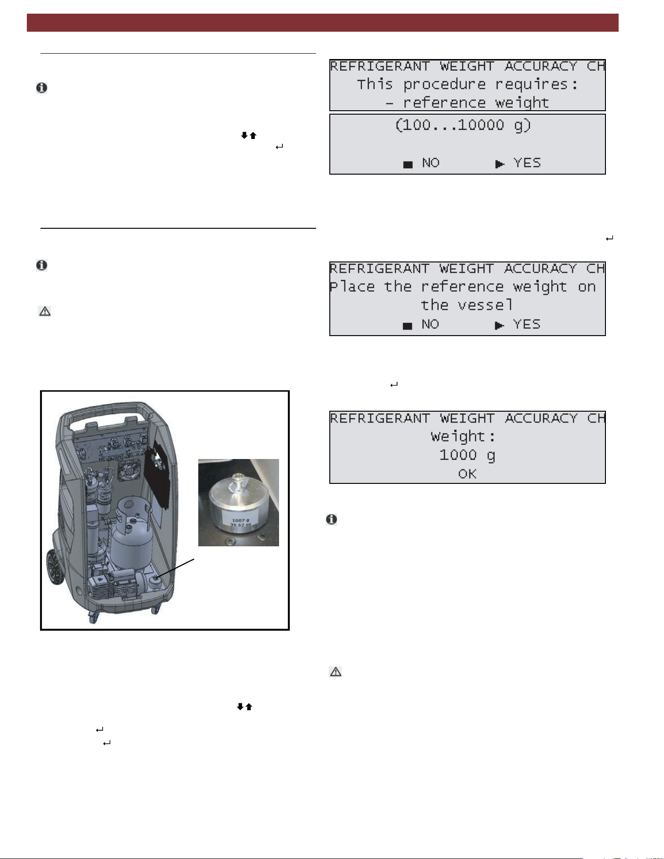
Before removing the front panel of the AC438, turn the
unit off and disconnect the power cord.
Fig. 33: Reference weight location
1 Reference weight
3. Connect the power cord to the power supply and switch
on the unit.
4. From the MAINTENANCE menu, press until REFRIG-
ERANT WEIGHT ACCURACY CHECK is highlighted
and press .
5. Press YES ( ) to continue when the screen in Fig. 34
appears.
Fig. 34: Refrigerant weight check screens
Fig. 35: Place weight screen
Fig. 36: Weight entry screen
7. Type the weight of the reference weight in the screen below
and press .
t
1
m
An automatic procedure is built in to the system that
allows the technician to check the accuracy of the
refrigerant weight scale.
1. Turn front locking nut using a flathead screwdriver and
carefully lift the front cover.
2. Unscrew the bolt and wingnut that hold the reference
weight to the base panel of the equipment.
6. Follow the instructions on the screen and when the screen
in Fig. 35 is displayed, place the reference weight below the
tank over the two screws of the load cell and press YES ( ).
The mass of the reference weight should be identified on a
side of the weight.
8. Allow unit to perform the check of the load cell calibration.
9. After the check is complete, a pass or fail result will be
displayed.
10. Switch off unit and disconnect the power cord.
11. Return reference weight to its position on the base panel
of the AC438 and reinstall front plastic.
12. Carefully close the front cover and secure the latch
using a flathead screwdriver.
In the case of a failure during the Refrigerant weight accuracy
check, perform the test a second time for verification. If the
resulting test is a second failure, a calibration of the internal
refrigerant weight scale should be performed.
Maintenance | AC438 | 25 | en
1901016-85
10.15 Printer maintenance (optional)
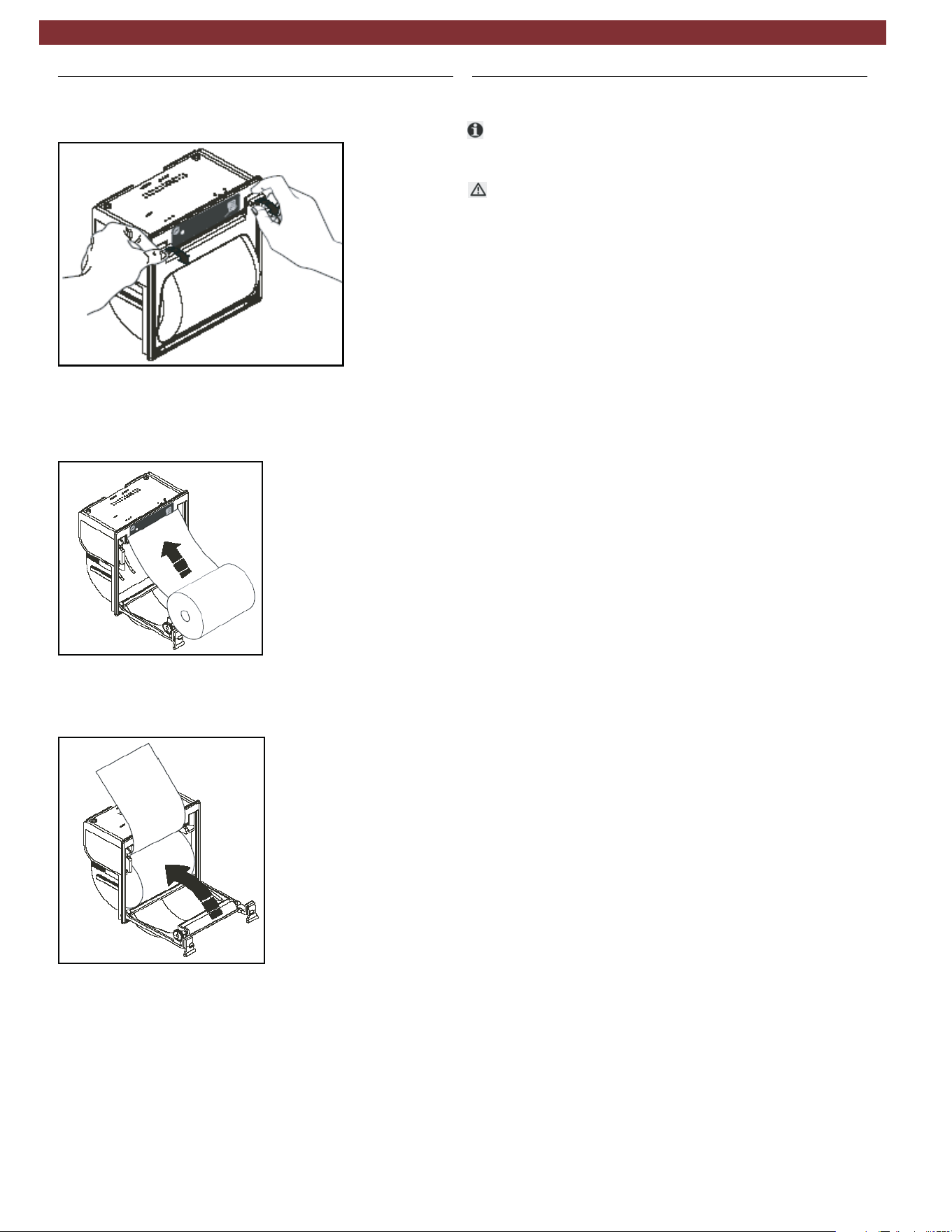
1. Open the lid of the printer as shown in Fig. 37.
Fig. 37: Opening printer
Fig. 38: Installing new paper roll
Fig. 39: Completing installation
2. Position the roll of paper inside the housing in the rotation
direction indicated in Fig. 38.
3. Pull the paper out of the housing as shown in Fig. 39 and
close the lid.
4. The printer is ready for printing.
10.16 Periodic checks
t
The AC438 service station must be checked over regularly
as set by local legislation.
m The following checks should be performed to ensure safe and
reliable operation:
— Make sure no corrosion or leakage is present in the in-
ternal cylinder and other metallic parts of the equipment
(under normal conditions the internal cylinder life is at
least 20 years).
— If automatic safety valve trips, contact technical support
to have unit inspected, resolve any issues and replace
valve if necessary.
— If the safety pressure switch trips, check the connection
of the cables and correct connection to the PCB. Contact
technical support for additional assistance.
— Check that external charging hoses - both red (HP) and
blue (LP) - are in good order and undamaged. In the case
of damaged hoses, discontinue use of AC438 until
replacement hoses are procured.
— Verify that vacuum pump oil and filter dryer have been
replaced according to schedule for proper functioning
equipment.
en | 26 | AC438 | Maintenance
1901016-85
11.
Spare parts
ter
AC80776
Vacuum pump oil AC80070
Paper for printer (5 rolls) AC83110
Service hose (HP) AC80532
Service hose (LP) AC80533
Quick-release coupling (HP) AC80495
Quick-release coupling (LP) AC80496
Safety goggles (accessory item) AC82956
Protective gloves (accessory item) AC82957
AC80147
Adapter LP (external bottle), US ACME 1/2
t
12. Disposal
12.1 A/C Service unit disposal
12.2 Recycled material disposal
12.3 Packaging disposal
At the end of its service life, this equipment must be disposed of
as follows:
—
—
Consign the unit to an authorized collection center
according to local legislation.
Contact the service center to have the refrigerant in the unit
recovered and recycled.
Return the refrigerant recovered from the unit to the
refrigerant supplier for local disposal or recycling.
The packaging must be disposed of in conformity with
local legislation.
This contributes to protecting the environment.
Lubricants extracted from the vehicle’s A/C system must
be returned to an official oil collection center.
Electronic and electrical A/C service equipment must never be
disposed of with domestic waste, but recycled appropriately.
—
—
m
—
—
Description Order number
Additional spare /replacement parts are available through
the service centers authorized by MATCO or by its reseller.
Contact technical support for replacement parts not listed
above.
Disposal | AC438 | 27 | en
1901016-85
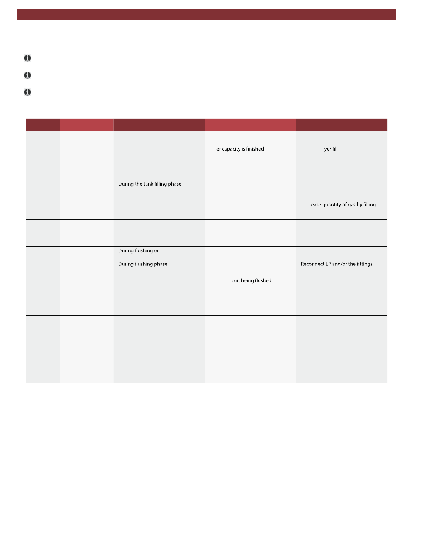
13. Troubleshooting
t Please contact technical service if any of the actions suggested in this section cannot be implemented.
t Notice/Warning codes are coded Wxxx on the title of the window.
t Alarm codes are coded
Axxx
on the title of the window - alarms terminate procedure and prevent its resumption.
13.1 AC438
noitcAsnoitulos elbissoPsrucco ti nehWsegasseMedoc rorrE
W008 REPLACE VACUUM
PUMP OIL
–When required after Pump Monitor-
ing system procedure
–Pump oil contaminated –Replace pump oil
W009 REPLACE DRYER
FILTER
–Every year since installation – Filt – Replace dr ter
W025 REFRIGERANT
QUANTITY TOO
HIGH
– During the programming of the in -
ner tank charge amount
– Amount required greater than that
available in internal tank
– Decrease the set quantity.
W026 RECHARGE CYL-
INDER EMPTY OR
DISCONNECTED
–
– Recharging tank empty
– Hoses/couplings are clogged/
closed
– Check tank, hoses, taps.
W029 CYLINDER NEAR-
LY FULL
– During the refrigerant recovery or
hoses emptying phase.
– Tank close to maximum capacity – Decr
(injecting) an external suitable tank
(with safety valve)
W032 NO PRESSURE -
VEHICLE WITHOUT
REFRIGERANT OR
DISCONNECTED
– During the refrigerant recovery
phase
– Hoses not connected
– Couplers not opened
– Check connections and leaks in
A/C system
W044 CYLINDER EMPTY –
Tank refrigerant
internal recycling phase
– Gas level is too low for the proce -
dure to be completed
– Fill the internal tank with gas
W045 LP VERY LOW,
CHECK CIRCUIT
BEFORE CONTIN -
UING
–
– LP hose disconnected
– Flushing couplings not properly
connected
– Leak in cir
–
and eliminate any leaks.
W047 POSSIBLE LEAK-
AGE
– During the refrigerant recovery
phase
– Vehicle A/C system may have leaks – Inspect vehicle A/C system and re -
pair
A000 EEPROM NOT
WORKING
tluaf scinortcelE– – EEPROM damaged – Replace the logic electronic board
A001 EEPROM DATA
CORRUPT
tluaf scinortcelE– – EEPROM damaged – Replace the logic electronic board
A002 PRESSURE SAFE-
TY SWITCH ACTI -
VATED
– Pressure above 18 bar – High pressure in the internal tank
– Circuit between compr
essor and
tank obstructed or closed
Verify:
– If internal CYLINDER pressure lev -
el is over 18 bar, wait for pressure
reduction, disconnect equipment
from the mains, use safety protec -
tion
– Open equipment and verify if the
valve between compressor and in -
ternal CYLINDER are open
en | 28 | AC438 | Troubleshooting
1901016-85
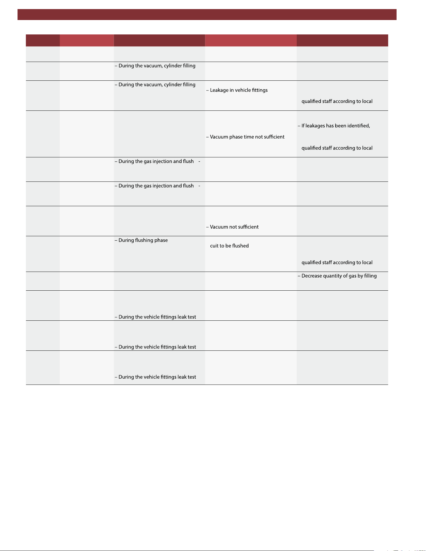
noitcAsnoitulos elbissoPsrucco ti nehWsegasseMedoc rorrE
A003 ADC NOT WORK -
ING
tluaf scinortcelE– – ADC analog-digital converter dam -
aged
– Replace the logic electronic board
A032 CIRCUIT STILL UN -
DER PRESSURE
or leak test phase in vacuum
– The vehicle A/C system is pressu -
rized
– Recover the refrigerant gas from
the vehicle before starting another
vacuum phase.
A033 CIRCUIT LEAKAGE
or leak test phase, both under pres -
sure and in vacuum
– Leakage in the circuit
– Identify the leak position in the ve -
hicle or connected system and
have it repaired by trained and
legislation.
A03 VACUUM LEVEL
TOO LOW
– During tracer injection and oil injec -
tion phase. The necessary vacuum
level has not been reached.
– Vehicle A/C system is pressurised
notwithstanding the vacuum phase
– Possible presence of leakages in -
side A/C system
or phase not executed (manual cy -
cle).
– Repeat cycle, increase vacuum
time
identify the leak position in the ve -
hicle or connected system and
have it repaired by trained and
legislation.
A035 CYLINDER EMPTY
ing phase
– Refrigerant gas is too low for the
procedure to be completed
– Refrigerant load cell out of calibra -
tion
– Fill the internal tank
– Check calibration and calibrate if
necessary
A036 CYLINDER REFRIG-
ERANT QUANTITY
TOO LOW
ing phase
– Gas amount in internal tank less
than required
– Refrigerant load cell out of calibra -
tion
– Fill the internal tank
– Check calibration and calibrate if
necessary
A037 FURTHER REFRIG-
ERANT INJECTION
NOT POSSIBLE
– During gas injection phase – Hoses not connected to vehicle
A/C system
– Couplers closed
– Presence of pressure in the circuit
– Caution: before proceeding, empty
out the hoses
– Repeat the recovery procedure and
increase the vacuum phase dura -
tion
A038 CIRCUIT LEAK-
AGE OR DISCON -
NECTED
–L
eakages or obstructions in the cir -
– Check the connection to the A/C
system
– Identify the leak in the circuit and
have it repaired by trained and
legislation.
A043 CYLINDER FULL – During the gas recovery and hoses
emptying phase
– Internal tank full (maximum capac -
ity level reached)
(injecting) an external suitable tank
(with safety valve)
A047 LP LEAKAGE – At the end of the gas injection or,
– In the Eco-Lock Lock patented
technology quick couplers discon -
nection phase, or
– Vehicle A/C system may have leaks
at the LP port
– Empty the vehicle (follow the pro -
cedure guided by the displayed
messages)
– Replace LP port/schrader valve in -
side LP port
A048HP LEAKAGE – At the end of the gas injection or,
– In the Eco-Lock Lock patented
technology quick couplers discon -
nection phase, or
– Vehicle A/C system may have leaks
at the HP port
– Empty the vehicle (follow the pro -
cedure guided by the displayed
messages)
– Replace HP port/valve inside HP
port
A049 LP AND/OR HP
LEAKAGE
– At the end of the gas injection or,
– In the Eco-Lock Lock patented
technology quick couplers discon -
nection phase, or
– Vehicle A/C system may have leaks
at the HP and/or LP ports
– Empty the vehicle (follow the pro -
cedure guided by the displayed
messages)
– Replace HP and/or LP ports/valves
inside ports
Troubleshooting | AC438 | 29 | en
1901016-85

14. Maintenance
14.1 Vacuum pump oil change
Vacuum pump oil change record
Date Maintenance technician identification Maint. tech. signature and stamp
en | 30 | AC438 | Maintenance forms
1901016-85

Vacuum pump oil change record
Date Maintenance technician identification Maint. tech. signature and stamp
Maintenance forms | AC438 | 31 | en
1901016-85

Filter Dryer Change Record
Job Date Maintenance technician identification Maint. technician signature and
stamp
Result of check
(pass/fail)
14.2 Filter dryer change
en | 32 | AC438 | Maintenance forms
1901016-85

Filter Dryer Change Record
Job Date Maintenance technician identification Maint. technician signature and
stamp
Result of check
(pass/fail)
Maintenance forms | AC438 | 33 | en
1901016-85

Filter Dryer Change Record
Job Date Maintenance technician identification Maint. technician signature and
stamp
Result of check
(pass/fail)
en | 34 | AC438 | Maintenance forms
1901016-85

14.3 Refrigerant load cell calibration check
Refrigerant Load Cell Calibration Check Record
Date
Result of check
(pass/fail)
Maintenance technician identification Maint. tech. signature and stamp
Maintenance forms | AC438 | 35 | en
1901016-85

Refrigerant Load Cell Calibration Check Record
Date Maint. tech. signature and stampMaintenance technician identification
Result of check
(pass/fail)
en | 36 | AC438 | Maintenance forms
1901016-85

Filter Dryer Change Record
Job Date Maintenance technician identification Maint. technician signature and
stamp
Result of check
(pass/fail)
14.4 Other checks/maintenance/repairs
Maintenance forms | AC438 | 37 | en
1901016-85

Filter Dryer Change Record
Job Date Maintenance technician identification Maint. technician signature and
stamp
Result of check
(pass/fail)
en | 38 | AC438 | Maintenance forms
1901016-85

15. Notes
Notes | AC438 | 39 | en
1901016-85

2019-01-23
035 82684 00 (REV. A)
1901016-85