
BMGL1020
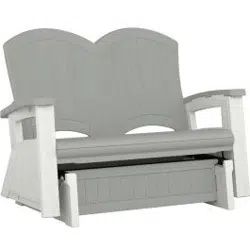
Adirondack
Glider
ASSEMBLY
INSTRUCTIONS
Tools
Required
Included
in
kit
0102104
Easy
Driver
Scan
QR
Code
for
product
assembly
video.
-v-
Brilliant
by
Design'
un
0
2023
Suncast
Corporation,
Batavia,
IL
0361707

Product
Registration:
Activate
Your
Limited
Warranty
Today!
Register
your
product
within
90
days
of
purchase
to activate
the
limited
warranty.
Simply
scan
the
QR
code
to
access
the
registration
page.
Fill
out
the
form
and
click "
Submit"
to
start
the
process.
To
read
about
your
product's
Limited
warranty
visit
https://www.suncast.com/warranty-information
or
call
US
1 (
800)
846-2345
Have
Questions?
We
are
here
to
help.
Check
out
our
resource
library
along
with
helpful
tips,
videos
and
FAQ's
at
https://support.suncast.com
You
may
call
the
Customer
Care
Center
directly
at: 1 (
800)
846-2345
or
write
Suncast
Corporation,
Customer
Care
Center,
701
N.
Kirk
Road,
Batavia,
IL
60510 (
USA)
To
purchase
Suncast
replacement
parts
and
learn
about
other
Suncast
products
visit
us
online or
call.
www.suncastcom
1-800-846-2345
or
1-630-381-6309.

A
Before
You
Begin...
•
Read
instructions
thoroughly
prior
to
assembly.
This
kit
contains
parts
that
can
be
damaged
if
assembled
incorrectly
or
in
the
wrong
sequence.
•
Please
follow
instructions.
Suncast
is
not
responsible
for
replacing
parts
lost
or
damaged
due
to
incorrect
assembly.
•
Check
for
all
parts
before
you
begin
assembly.
Using
the
provided
parts
check
list,
verify
that
you
have
all
the
parts
required
to
assemble
your
glider.
• •
•
Assistance
is
required
during
portions
of
assembly.
ente)
A
Caution
•
WARNING:
Failure
to
observe
safety
cautions,
improper
assembly,
or
incomplete
assembly
will
void
the
product
warranty
and
may
result
in
damage
to
the
product
and/or
serious
injury.
•
DO
NOT
exceed
500
lbs
total
weight
distributed
across
the
glider.
•
DO
NOT
use
the
product
if
parts
are
missing,
damaged
or
worn.
Contact
Suncast
for
further
assistance.
•
DO
NOT
stand
on
glider
or
use
glider
in
any
way
other
than as
intended.
Glider
is
designed
and
intended
for
sitting
only.
•
DO
NOT
sit
on
arm
rest
or
back
of
the
glider.
•
DO
NOT
use
glider
on uneven
surfaces.
Glider
is
designed
to
be
used on
level
ground
only.
•
DO
NOT
use
or
store
product
in
close
proximity
to
hot
objects
including
but
not
limited
to
open
flames,
grill,
heater
or
similar
items.
•
Make
sure
all
bolts
and
parts
are
securely
tightened
before
using
the
product
and
periodically
recheck.
•
To
ensure
safety,
children
must
be
carefully
supervised
on
glider
at
all
times.
Care
Instructions
To
maintain
the
look
of
your
product,
we
recommend
cleaning
it
at
regular
intervals
with
mild
soap
and
water.
DO
NOT
use
bleach,
ammonia
or
other
caustic
cleaners,
and
DO
NOT
use
stiff
bristle
brushes.
Failure
to
perform
cleaning
at
regular
intervals
could
result
in
permanent
staining
of
the
plastic.
This
type
of
damage
is
not
covered
under
warranty.
3

Parts -
Seat
and
Base
o
OB00835
Right
Front
1
o
OB00850
Right
Armrest
OB00833
Right
Base
OB00852
Seat
Back
OB00837
Right
Side
OB00847
Front
Crossbeam
OB00846
Base
Front-
Back
2
OB00834
Left
Front
OB00851
Back
Support
o
OB00849
Left
Armrest
OB00832
Left
Base
OB00836
Left
Side
4

Parts -
Steel
n
0
o
o
o
o
0
cb
o
o
,
OMP000057
OMP000058A
0280672
0280673
Tube
Strap
Support
Bracket
Support
Tube
Threaded
Rod
x2 x2 x2
x2
5

Parts -
General
0102197
Angle
Bracket
x4
(I)
0632533
Glider
Stop
x2
0102793
Tube
Connector
x4
é)
0632529 0511013
Tube
Endcap
Glider
Bearing
x4
x4
6

Hardware
0480554 -
Hardware
Bag
0632530
1/4"
Flat
Washer
x14
0632532
0632542
1/4-20
x
2"
Bolt #
8 x
2"
Screw
x11
x4
0632531
1/4-20
Locknut
x14
010256307
Easy
Bolt
x28
efE2ZID
,
eieEED
,
*0632521
Hex
Key -
6mm
0630821
0631147 0632515
#10
x
5/8"
1/4-20
x
1/2
Bolt
Threaded
Insert
Truss
Head
Screw
x9 x9
Hardware
shown
at
actual
size (*
Unless
otherwise
noted.)
Extra
hardware
provided.
Not
all
are
used.
7

Pre-
Assembly
Important:
It
is
recommended
to
assemble
this
product
on
a
non-
marking,
solid
surface
that
will
not
damage
the
product.
If
necessary, place
a
drop
cloth
or
other
similar
material
on
the
assembly
surface
to
avoid
damaging
the
product.
This
item
uses
self-
tapping
screws
in
some
areas.
There
are
no
pre-
drilled
holes.
Use
force
when
starting
to
drive
the
screw.
Once
the
screw
pierces
the
plastic
it
will
drive
easier.
13
Using
a
Phillips
head
screwdriver
or
other
similar
tool,
pierce
holes
indicated
in
left (
A)
and
right (
B)
base
panels
as
well
as
the
left (
D)
and
right (
E)
side
panels.
(Wit)
Ann\
AMU\
o
Pre-
Assembly -
Seat
Base
Paying
close
attention to
the
orientation
shown,
place
one
support
bracket (
0) over
the
right
base
panel (
B).
Be
sure
the
support
bracket
sits
fully
and
squarely
over
the
top
of
the
panel.
NOTE:
Orientation
can
be
referenced
by
the
location
of
the
cutout
slot
indicated.
8

(P
x2
(R)
x2
(S)
x2
ra
Through
the
hole
indicated,
install
one
bolt (
P),
glider
stop (
Q),
washer (
R)
and
locknut (
S)
through
the
sup-
port
bracket (
0)
and
right
base
panel (
B).
Tighten
the
bolt
and
locknut
securely.
Do
not
overtighten.
7/16"
(R)
x1
(S)
x1
Using
one
bolt (
P),
washer (
R)
and
locknut (
S)
each
through
the
two
end
holes
of
the
support
bracket (
0),
install
two
glider
bearings (
T)
to
the
support
bracket
(0)
and
right
base
panel (
B) .
Tighten
the
bolt
and
locknut
securely.
Do
not
overtighten.
113
Repeat
Steps
2-4
to
assemble
the
left
base (
A) to mirror
the
right
base (
B).
9

Pre-
Assembly -
Seat
(V)
x8
Using
the
included
alien
wrench (
U),
insert
eight
threaded
inserts (
V)
into
the
seat (
F)
at
the
locations
indicated.
Ox8
c;>
Pre-
Assembly -
Support
Tube
13
Insert
one
tube
endcap (
W)
into
each
end
of
the
support
tubes (
X).
10

Assembly -
Base
(Y)
x2
(Y)
x2
Important:
It
is
recommended
to
assemble
this
product
on
a
non-
marking,
solid
surface
that
will
not
damage
the
product.
If
necessary, place
a
drop
cloth
or
other
similar
material
on
the
assembly
surface
to
avoid
damaging
the
product.
This
item
uses
self-
tapping
screws
in
some
areas.
There
are
no
pre-
drilled
holes.
Use
force
when
starting
to
drive
the
screw.
Once
the
screw
pierces
the
plastic
it
will
drive
easier.
While
aligning
the
easy
bolt
holes
and
sockets,
position
the
left
base
panel (
A)
together
with
one
base
front/back
panel (
C) (
either
panel
will
work).
Secure
the
panels
using
two
easy
bolts
(
Y).
Tighten
the
easy
bolts
securely (
3-4
clicks).
While
aligning
the
easy
bolt
holes
and
sockets,
position
the
right
base
panel (
B)
together
with
the
opposite
end
of
the
previous
base
front/back
panel (
C).
Secure
the
panels
using
two
easy
bolts
(
Y).
Tighten
the
easy
bolts
securely
(3-4
clicks).
o
Od
ip,
ux2
11

Assembly -
Base (
cont.)
Slide
the
remaining
base
front/back
panel (
C)
between
the
left (
A)
and
right (
B)
base
panels.
Align
the
easy
bolt
holes
and
sockets.
al
Secure
the
panels
using
two
easy
bolts
(
Y)
on each
end
of
the
base
front/back
panel (
C).
Tighten
the
easy
bolts
securely (
3-4
clicks).
(Y)
x4
12

In
Slide
the
two
threaded
rods (
Z)
through
the
remaining
holes
in
the
left (
A)
and
right (
B)
base
panels
until
equal
lengths (
b)
of
the
rods
extend
past
either
base
panel.
hlei
CD
Using
pliers
to
hold
the
threaded
rods (
Z),
secure
the
threaded
rods
using
two
washers (
R)
and
locknuts (
S)
each.
One
set
on each
end.
Tighten
the
locknuts
on
both
sides
evenly.
Do
not
overtighten.
(R)
x4
(S)
x4
Completed
Base
13

Insert
the
tabs
of
the
front
crossbeam (
G)
into
the
front
slots
in
the
under-
side
of
the
seat (
F)
and
slide
as
shown
to
lock
the
crossbeam
into
place.
Be
sure
the
ends
of
the
crossbeam
are
flush
with
the
ends
of
the
seat.
El
Place
one
support
tube (
X)
into
the
long
rear
slot
in
the
under-
side
of
the
seat (
F).
Place
two
tube
connectors (
AA)
over
the
support
tube
at
the
locations
indicated
and
secure
with
two
bolts (
BB)
each.

ID
(Y)
x2
Place
the
remaining
support
tube (
X)
into
the
long
front
slot
in
the
under-
side
of
the
seat (
F).
Place
two
tube
connectors (
AA)
over
the
support
tube
at
the
locations
indicated
and
secure
with
two
bolts (
BB)
each.
(BB)
x4
With
the
left
side
panel (
D)
and
seat
assembly (
F,
G)
oriented
as
shown,
position
the
side
panel
against
the
support
tubes (
X)
and
align
the
mounting
holes.
Secure
the
left
side
panel
and
seat
assembly
together
using
two
easy
bolts
(
Y).
Tighten
the
easy
bolts
securely (
3-4
clicks).
NOTE:
The
support
tubes
should
nest
into
the
recesses
of
the
left
side
panel (
D).
o
15

Assembly -
Seat (
cont.)
(P)
x2
Place
one
angle
bracket (
CC)
to
the
inside
corner
where
the
left
side
panel
D
and
seat
assembly (
F,
G)
meet
and
secure
using
two
easy
bolts
(
Y).
Tighten
the
easy
bolts
securely (
3-4
clicks).
(Y)
x2
NOTE:
Bolts ( P)
are
used
for
location
purposes
only
at
this
time.
Near
the
same
location
as
the
previous
assembly,
place
one
tube
strap (
DD)
against
the
ends
of
the
support
tubes (
X).
Insert
two
bolts (
P)
through
the
holes
nearest
the
ends
of
the
tube
strap
and
the
support
tubes
as
shown.
With
the
tube
strap
held
in
place
by
the
inserted
bolts,
secure
the
tube
strap
to
the
left
side
panel (
D)
using
two
screws (
EE).
IMPORTANT:
Remove
the
two
bolts (
P)
to
be
used
later
in
the
assembly.
(EE)
x2
16

ai
Repeat
steps
17-19
to
secure
the
right
side
panel (
E)
to
the
seat
assembly (
F,
G).
Rotate
the
seat
into
an
upright
position.
Insert
the
slots
in
the
left
front
panel (
H)
onto
the
front
tabs
of
the
left
side
panel (
D).
Slide
downward
to
lock
the
left
front
panel
into
place.
Be
sure
the
left
front
panel
is
fully
seated
onto
the
left
side
panel.
Repeat
the
process
to
attach
the
right
front
panel (
J)
to
the
right
side
panel (
E).
17

Assembly -
Seat (
cont.)
cm
With
the
help
of
another
person,
align
the
tabs
on
the
sides
of
the
seat
back
panel (
K)
with
the
slots
in
the
left
and
right
side
panels (
D,
E)
and
slide
the
seat
back
assembly
downward
towards
the
seat (
F).
Align
the
center
tabs
with
the
slots
in
the
seat.
While
holding
the
seat
back
in
place,
use
a
rubber
mallet
to
tap the
seat
upward
to
engage
the
center
tabs.
NOTE:
Before
engaging
the
center
tabs
into
the
seat,
be
sure
the
side
tabs
are
correctly
engaged
with
the
left
and
right
side
panels.
Ea
Secure
the
seat
back
assembly
to
the
seat
using
four
screws
(
FF)
through
the
center
tabs.
Tighten
securely.
(FF)
x4
18

While
tipping
the
front
of
the
left
armrest (
N)
upward,
slide
the
left
armrest
into
position
over
the
left
side
panel (
D).
Be
sure
the
left
armrest (
N)
is
fully
seated
between
the
left
side
panel (
D)
and
the
seat
back (
K).
Tilt
the
front
of
the
left
armrest (
N)
downward
to
rest
on
the
top
of
the
left
side
panel (
D).
el
19

Assembly -
Seat (
cont.)
1)
Secure
the
left
armrest (
N) to
the
left
side
panel (
D)
using
one
easy
bolt
(
Y).
2)
Secure
the
left
armrest (
N) to
the
left
front
panel (
H)
using
one
angle
bracket (
CC) and
two
easy
bolts
(
Y).
3)
Secure
the
left
armrest (
N) to
the
left
seat
back
panel (
K)
using
one
easy
bolt
(
Y).
Tighten
all
easy
bolts securely (
3-4
clicks).
Repeat
Steps
24-26
to
install
the
right
armrest (
M)
to
the
right
side
panel (
E),
right
front
panel (
J)
and
right
seat
back
panel (
K).
(Y)
x4
Ea
Rotate
seat
onto
its
front
face
as
shown.
20

With
the
seat
resting
on
its
front
face,
align
the
back
support (
L)
over
the
left (
N)
and
right (
M)
armrests
and
against
the
seat
back (
K).
Secure
the
lower
back
support
using
four
easy
bolts
(
Y).
Tighten
easy
bolts securely (
3-4
clicks).
(Y)
x4
4
21

2)
Carefully
slide
the
base assembly
between
left (
D)
and
right (
E)
side
panels
until
the
glider
bearings
are
near
the
ends
of
the
support
tubes (
X).

On
both
left
and
right
sides
of
the
seat
and
base,
align
and
slide
the
upper
bolts (
P)
through
the
support
tubes (
X)
and
secure
using
two
washers (
R)
and
locknuts (
S).
Finger
tighten
the
locknuts
only
at
this
time.
(R)
x2
7/16"
(S)
x2
With
the
upper
bolts
installed,
align
and
slide
the
lower
bolts (
P)
through
the
support
tubes (
X)
and
secure
using
two
washers (
R)
and
locknuts (
S).
Tighten
the
bolts
and
locknuts
securely.
Do
not
overtighten.
Hint:
With
the
help
of
another
person,
push
the
lower
side
of
the
base
toward
the
seat
to
align
the
lower
bolts
with
the
support
tubes.
Tighten
the
upper
bolts
and
locknuts
securely.
Do
not
over-
tighten.
(R)
x2
(S)
x2
23

With
the
seat
and
base
securely
fastened
together,
follow
the
below
procedure
to
tilt
the
seat
and
base
to
an
upright
position:
1)
Lift
the
base
upward.
2)
Rotate
the
base
away
from
the
seat.
3)
Carefully
lower
the
base
until
the
bottom
front
edge
touches
the
ground.
4)
Tilt
the
seat
backward
and
over
the
base.
5)
Allow
the
base
to
fully
contact
the
ground.
6)
Guide
the
seat
backward
to
rock
into
an
upright
position.
51_1/7Me57: