Ice-O-Matic
11100 East 45th Ave
Denver, Colorado 80239
11-1000 Date 8/22/15
SERVICE AND INSTALLATION MANUAL
THE ICE SERIES CUBERS
ICE0250 through ICE2100 SERIES*
*Includes Undercounter and 22 Inch Series

ICE Series Notes
Ice-O-Matic has partnered with ENERGY STAR since 2004 to ensure our customers receive the
most efficient ice machines for your investment dollar. Ice-O-Matic is committed to the continuous
improvement in both energy efficiency and productivity thereby delivering the best value in energy
efficient ice machines money can buy.
For a detailed list of ENERGY STAR qualified Ice-O-Matic ice machines, go to:
http://www.iceomatic.com/Products/Sales-Literature/#
Plant-a-Tree Program
As part of our commitment to the global environment, Ice-O-Matic is devoted to sustainability
in every aspect of our business. To offset the carbon footprint of our factory in Denver, we
not only recycle materials in our packaging and manufacturing but also recycle our industrial
and office waste products.
More important, we partner with AMERICAN FORESTS and plant a tree for every ice
machine we sell, thereby supporting reforestation of key regions throughout the world. Our
goal is to plant 150,000 trees through our Global Sustainability program. Trees reduce
topsoil erosion, prevent harmful land pollutants from getting into our waterways and replace
air pollutants with fresh, clean oxygen.
Ice-O-Matic Warranty
Every Ice-O-Matic ice maker is backed by a warranty that provides both parts and labor coverage. To view the
warranty details, register products, or check your warranty status visit the “Warranty and Water Filter
Registration” page on www.iceomatic.com
This manual belongs to:_______________________________________
Always feel free to contact the Ice-O-Matic Service Department with any questions or
comments.
Ice-O-Matic
11100 East 45
th
Avenue
Denver, Colorado 80239
Telephone: (303) 371-3737
Toll Free: (800) 423-3367
FAX: (303) 576-2944
After Hours Emergency Technical Support
(888) FIX-4-ICE (888 349-4423)
Additional Telephone Numbers
Contact: ( Area Code) Phone Number
________________________________________________________________

ICE Series Notes
Table of Contents
Table of Contents Page A1
General Information
How To Use This Manual Page A2
Model And Serial Number Format Page A3
Electrical And Mechanical Specifications Page A5-A8
Installation Guidelines Page A9
Electrical And Plumbing Requirements Page A10-A17
Remote Condenser Installation Page A18-A19
How The Machine Works Page A20
Undercounter Model Bin Removal Page A21-A22
Warranty Information Page A23-A24
Scheduled Maintenance
Maintenance Procedure Page B1
Cleaning and Sanitizing Instructions Page B1-B2
Winterizing Procedure Page B3
Cabinet Care Page B4
Troubleshooting Trees
How to Use The Troubleshooting Trees Page C1
Troubleshooting Trees Table Of Contents Page C2
Troubleshooting Trees Page C3-C18
Water System
Water Distribution And Components Page D1-D5
Refrigeration System
Refrigeration Cycle And Components Page E1
Harvest Cycle Page E5
Remote System Page E5-E6
Pump Down System Page E7
Refrigerant Specifications Page E8-E20
Electrical System
Control Circuit Page F1
Compressor And Start Components Page F1-F2
Untimed Freeze Cycle Page F3
Timed Freeze Cycle Page F4
Harvest Cycle Page F5-F9
Pump Down System Page F9
Wiring Diagrams Page G1

ICE Series Table Of Contents
Page A1
Table of Contents
Table of Contents Page A1
General Information
How To Use This Manual Page A2
Model And Serial Number Format Page A3
Installation Guidelines Page A5
Electrical And Plumbing Requirements Page A6-A13
Remote Condenser Installation Page A14-A15
How The Machine Works Page A16
Undercounter Model Bin Removal Page A17-A18
Warranty Information Page A20
Scheduled Maintenance
Maintenance Procedure Page B1
Cleaning and Sanitizing Instructions Page B2-B3
Winterizing Procedure Page B4
Cabinet Care Page B5
Troubleshooting Trees
How to Use The Troubleshooting Trees Page C1
Troubleshooting Trees Table Of Contents Page C2
Troubleshooting Trees Page C3-C18
Water System
Water Distribution And Components Page D1-D5
Refrigeration System
Refrigeration Cycle And Components Page E1
Harvest Cycle Page E5
Remote System Page E5-E6
Pump Down System Page E7
Electrical System
Control Circuit Page F1
Compressor And Start Components Page F1-F2
Untimed Freeze Cycle Page F3
Timed Freeze Cycle Page F4
Harvest Cycle Page F5-F9
Pump Down System Page F9
Electrical Sequence ICE1400-2100 Version 3 Page F10
Wiring Diagrams Page G1
Cuber Performance Data Page H1
Specifications Page I1

ICE Series General Information
Page A2
How To Use This Manual
Ice-O-Matic provides this manual as an aid to the service technician in installation, operation,
and maintenance of the ICE Series (electro-mechanical) cube ice machines. If used properly
this manual can also assist the service technician to troubleshoot and diagnose most of the
problems that may occur with the machine.
The first two sections of this manual provide general information and maintenance information.
The remainder of the manual beginning with Section C provides troubleshooting and service
information. Section C contains flow charts called troubleshooting trees. Page C-1 provides
instructions on using the troubleshooting trees. Each troubleshooting tree is named to describe
a particular problem with the operation of the machine.
When following the troubleshooting trees, the service technician will be led through questions
and checks and end up with a probable solution. When using the troubleshooting trees, it is
important that the service technician understand the operation and adjustments of the
components being checked and the component suspected of malfunctioning. A detailed
description of the operation and adjustments of the components as well as other service
information is available in the pages that follow Section C.
Sections D, E, and F focus on a particular system in the ice machine: water distribution system,
refrigeration system, and it is important that these sections be used together with the
Troubleshooting Trees in Section C.
Most aspects of the ICE Series machines are covered in this manual, however, should you
encounter any conditions not addressed herein, please contact the Ice-O-Matic Technical
Service Department for assistance. You may also e-mail or write the Ice-O-Matic Technical
Service Department:
Ice-O-Matic
11100 E. 45
th
Ave.
Denver, Co. 80239
Attn: Technical Service Department
E-Mail: [email protected]
Telephone Numbers Any Service communication must include:
800-423-3367 All Department Model Number
888-349-4423 Technical Assistance Only Serial number
303-371-3737 A detailed explanation of the problem
Note the warning symbol where it appears in this manual.
It is an alert for important safety information on a hazard
that might cause serious injury.
Keep this manual for future reference.
The ICE Series Service Parts Manuals are available separately.
Ice-O-Matic products are not designed for outdoor installation.

ICE Series General Information
Page A3
Model and Serial Number Format
Model Numbers
ICE 040 0 H A
Condenser Type: A=Air W=Water R=Remote T=Top Discharge Air Cooled
Cube Size: H=Half (3/8x7/8x7/8) F=Full (7/8x7/8 x7/8) G=Grande (1¼x1⅛x7/8)
Voltage: 0=115V 5=240/50/1 6=208-230/60/1 7=208-230/60/3
Approximate 24 hour ice production: (x 10 @ 70°F/21°C Air and 50°F/10°C Water)
Series: Slab ice cuber, Stainless Steel Cabinet
Serial Number Date Code (Prior to August 2004)
The first letter in the serial number indicates the month and decade of manufacture.
The first digit in the serial number indicates the year of manufacture.
Example: A0XX-XXXXX-Z is manufactured January 2000
A1XX-XXXXX-Z is manufactured January 2001
1990-1999 MONTH 2000-2004
M JANUARY A
N FEBRUARY B
P MARCH C
Q APRIL D
R MAY E
S JUNE F
T JULY G
U AUGUST H
V SEPTEMBER I
W OCTOBER J
Y NOVEMBER K
Z DECEMBER L
Note: The letter O and letter X are not used.
Reference new serial number format on next page.
ICE Series General Information
Page A4
Model and Serial Number Format
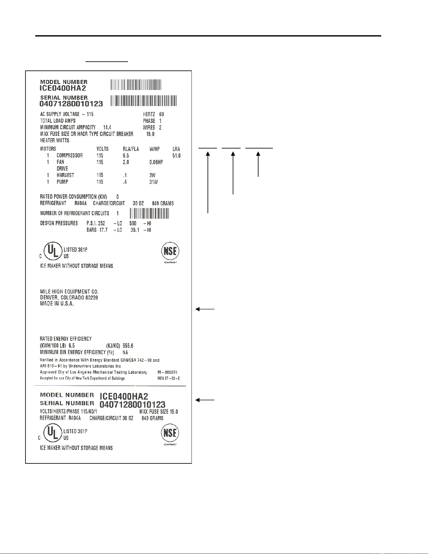
Sample Only
This format is 14 characters long and begins with a
date code followed by the Ice-O-Matic identifier, and
then a sequential number. This is an entirely
numerical serial number.
The new serial number will look like the example.
0407 1280 010123
010123 is the serial identifier.
1280 is the identifier. (Ice-O-Matic)
0407 is the date code, in YYMM format. (2004 July)
The date code will change monthly and yearly to
reflect the date of manufacture.
Large data plate will be placed on the back of
the unit.
Small data plate will be placed by the service
valves.

ICE Series General Information
Page A5
Installation Guidelines
Note: Installation should be performed by an Ice-O-Matic trained Service Technician.
For proper operation of the Ice-O-Matic ice machine, the following installation guidelines must be
followed. Failure to do so may result in loss of production capacity, premature part failures, and
may void all warranties.
Ambient Operating Temperatures
Minimum Operating Temperature: 50°F (10°C)
Maximum Operating Temperature 100°F (38°C), 110°F (43°C) on 50 Hz. Models.
Note: Ice-O-Matic products are not designed for outdoor installation.
Incoming Water Supply (See Plumbing Diagram for line sizing Page A6-A13)
Minimum incoming water temperature: 40°F (4.5°C)
Maximum incoming water temperature: 100°F (38°C)
Minimum incoming water pressure: 20 psi (1.4 bar)
Maximum incoming water pressure: 60 psi (4.1 bar)
Note: If water pressure exceeds 60 psi (4.1 bar), a water pressure regulator must be
installed.
Drains: All drain lines must be installed per local codes. Flexible tubing is not recommended.
Route bin drain, purge drain and water condenser drain individually to a floor drain. The use of
condensate pumps for draining water is not recommended by Ice-O-Matic. Ice-O-Matic assumes
no responsibility for improperly installed equipment.
Water Filtration: A water filter system should be installed with the ice machine.
Clearance Requirements: Self contained air cooled ice machines must have a minimum of 6
inches (15cm) of clearance at the rear, top, and sides of the ice machine for proper air circulation.
Stacking: Ice-O-Matic does not endorse stacking ice machines.
Dispenser Application: A thermostatic bin control kit must be installed if the ICE Series ice
machine is placed on a dispenser. A bin top may or may not be required. (Exception is the
CD400 Dispenser)
Electrical Specifications: Refer to the serial plate at the rear of the ice machine or the charts
starting on page H1.
Adjustments
Level the machine within 1/8 inch in all directions.
Check the bin control for proper adjustment, Page F9
Check the water in the water trough for proper level, Page D1
Check the ice bridge for proper thickness, Page F4
Check the cam switch adjustment. Page F8
Check the water regulating valve adjustment if water cooled, Page E2
ICE Series General Information
Page A6
Electrical and Plumbing Requirements: ICEU150, ICEU200, ICEU205 and ICEU206
ICE Series General Information
Page A7
Electrical and Plumbing Requirements: ICEU150, 220, 225 and 226
Note: The ICEU150, ICEU220, ICEU225
and ICEU226 do not have a splash
curtain.
These models utilize a thermostatic
bin control in place of a mechanical
bin switch.
ICE MAKER WATER-IN
3/8 FPT OR 1/4 Male Flare
ICE Series General Information
Page A8
Electrical and Plumbing Requirements: ICEU300 and 305
Note: The ICEU300 does not have a
splash curtain.
This model utilize a thermostatic bin
control in place of a mechanical bin
switch.
ICE MAKER WATER-IN
3/8 FPT OR 1/4 Male Flare
ICE Series General Information
Page A9
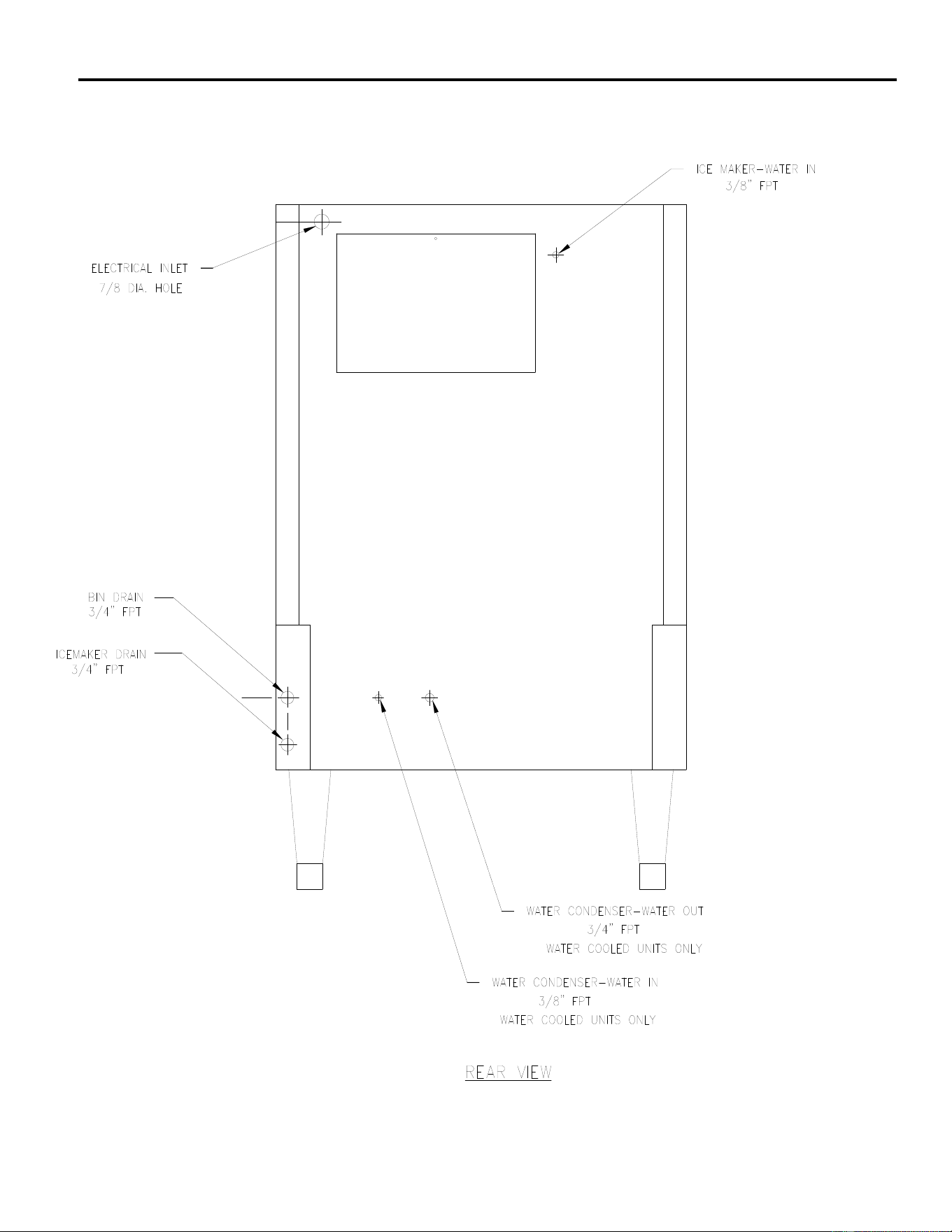
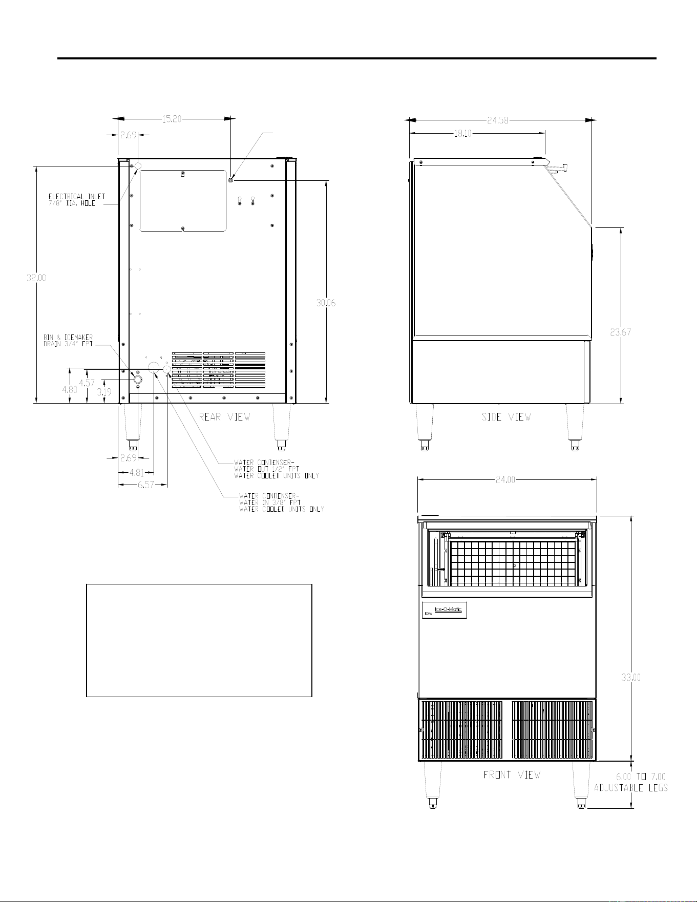
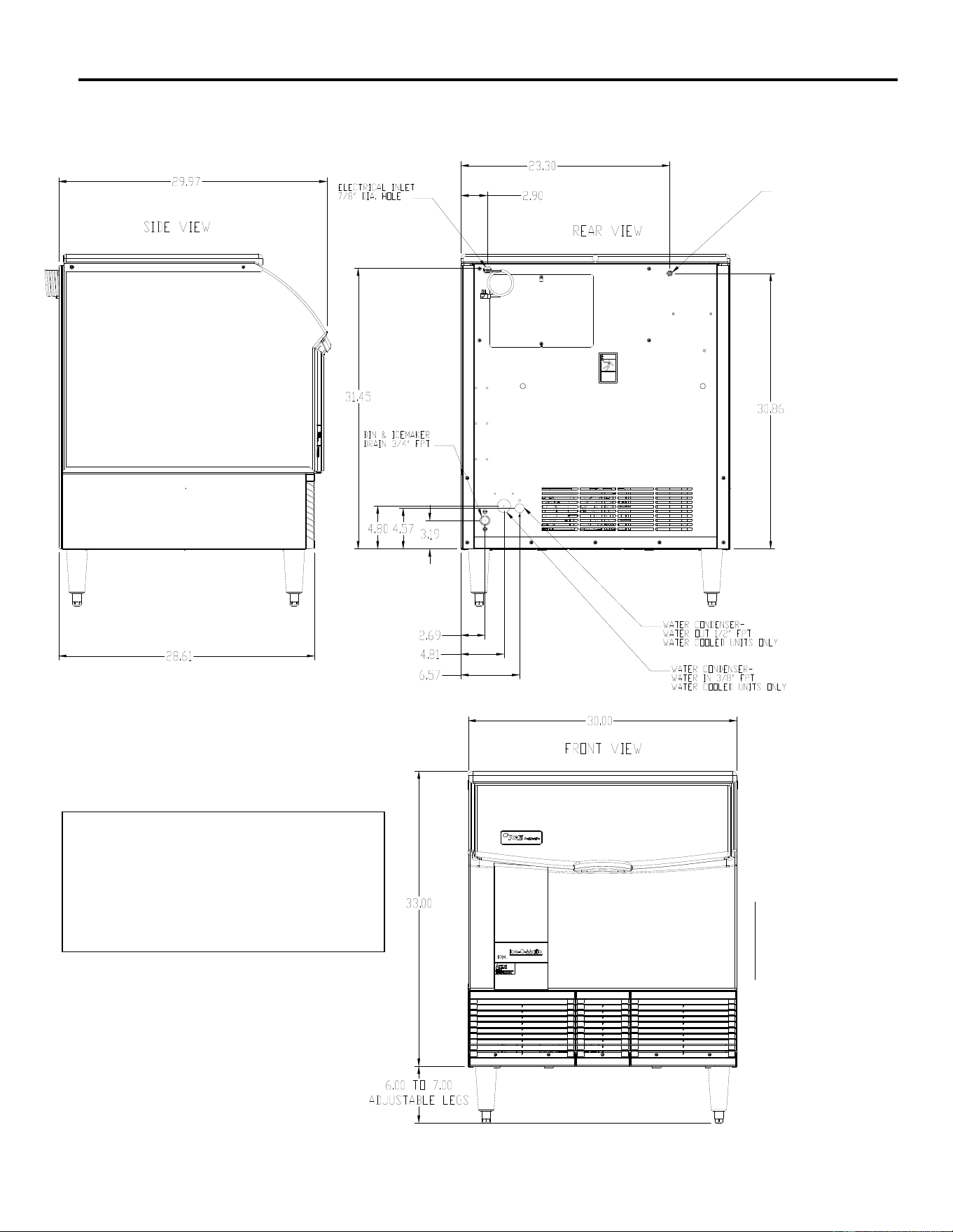
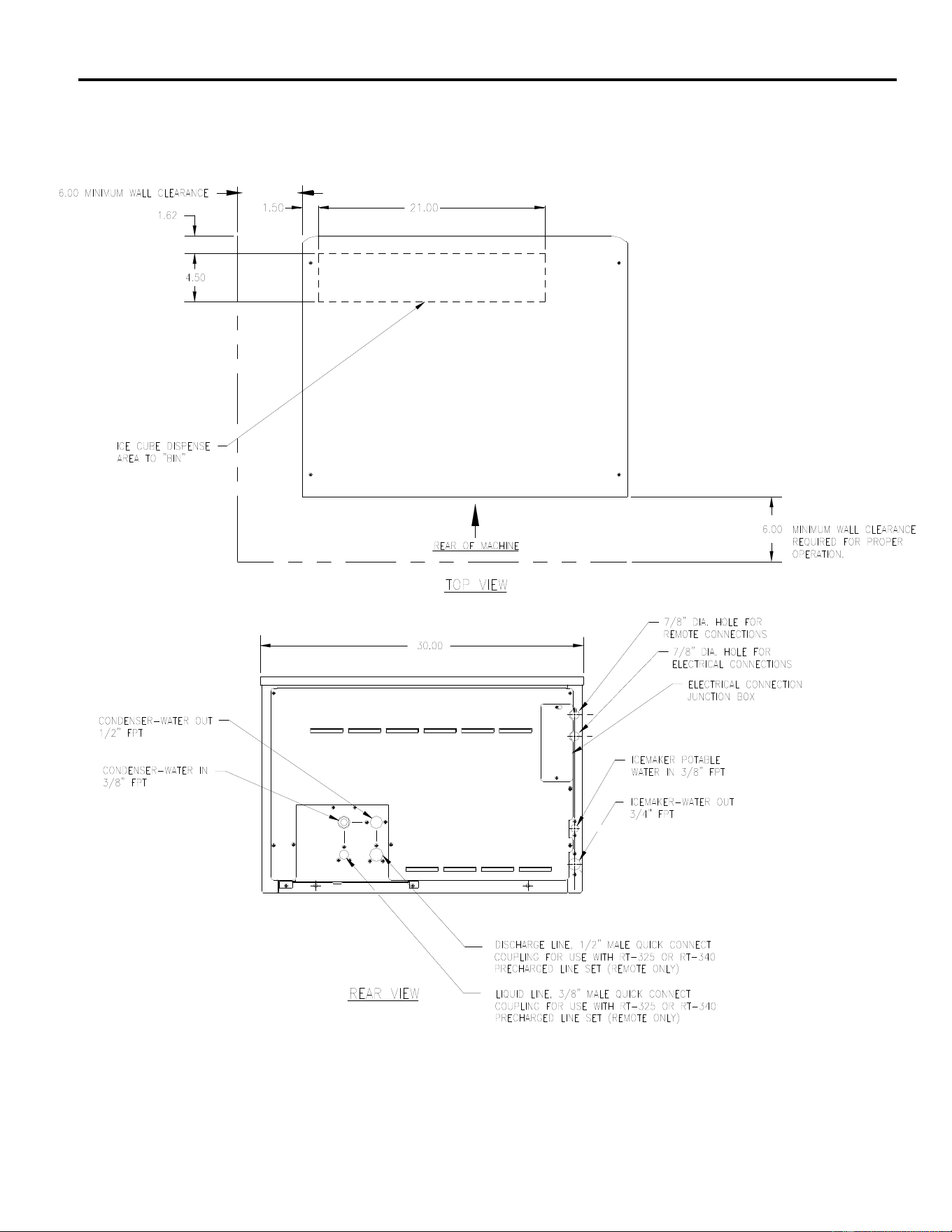
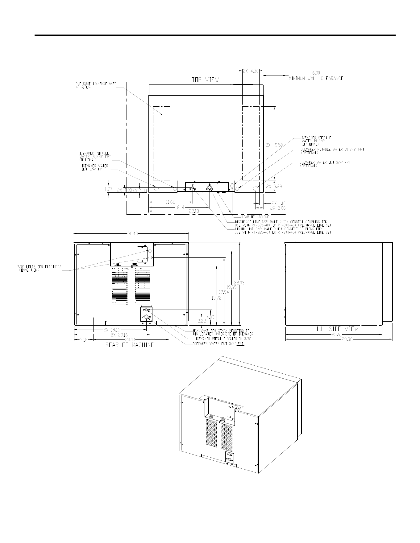
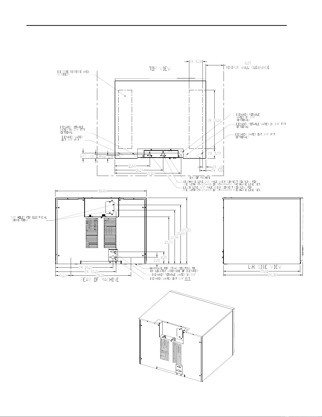
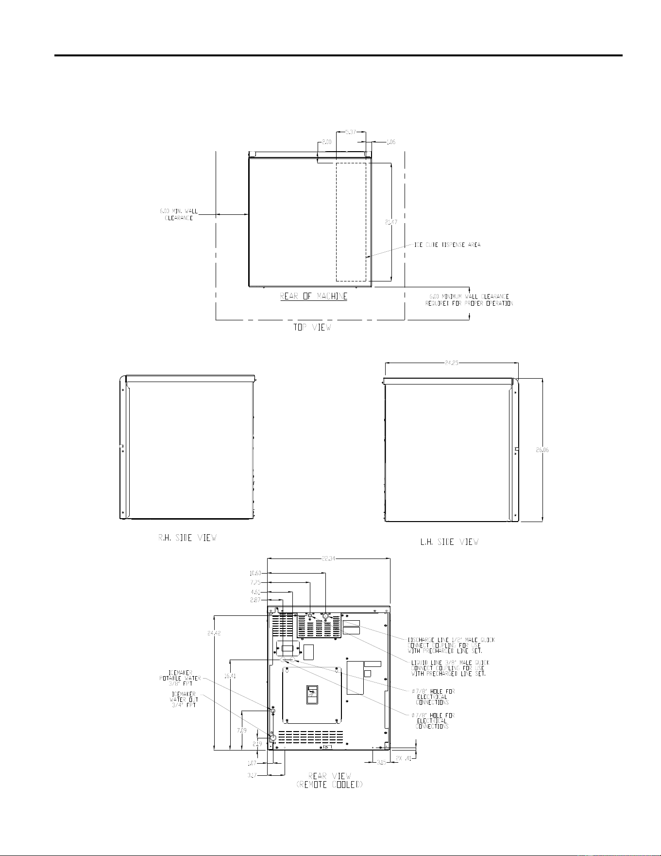
Electrical and Plumbing Requirements: ICE0250, ICE0400, ICE0500, ICE0606, ICE0806
and ICE1006 (30 Inch Wide Cubers) ICE0855, ICE0856 and ICE1006
ICE Series General Information
Page A10
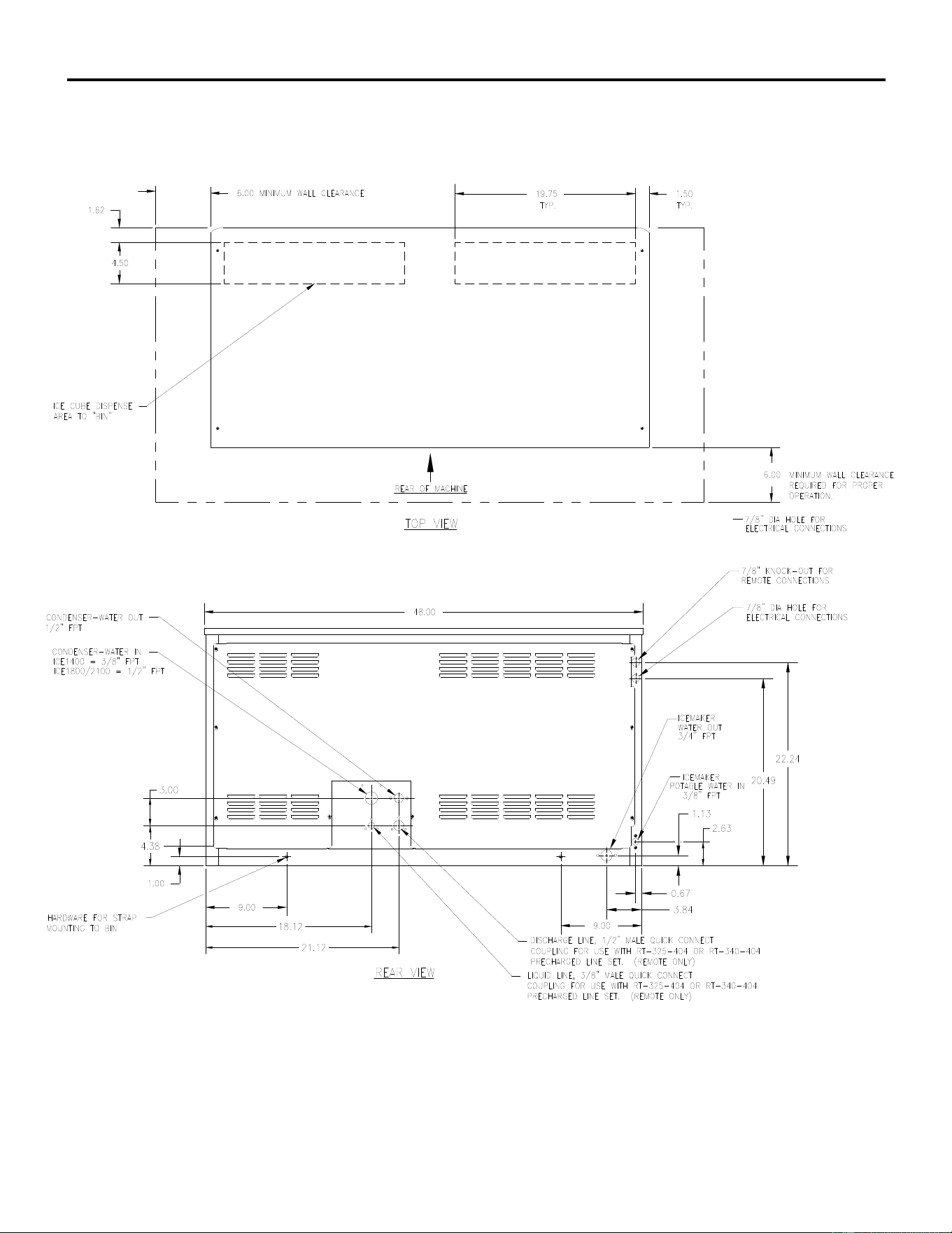
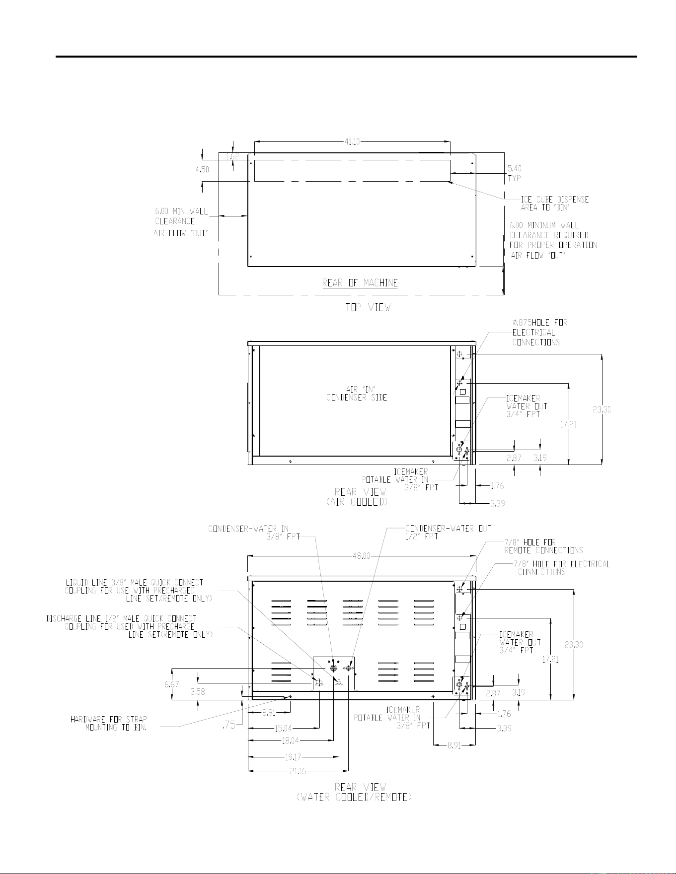
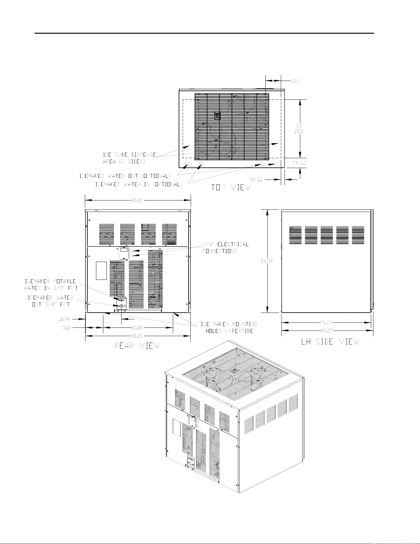
Electrical and Plumbing Requirements: ICE1406, ICE1806, ICE2106 (48 Inch Wide Cubers)
Prior to January 2008
ICE Series General Information
Page A11
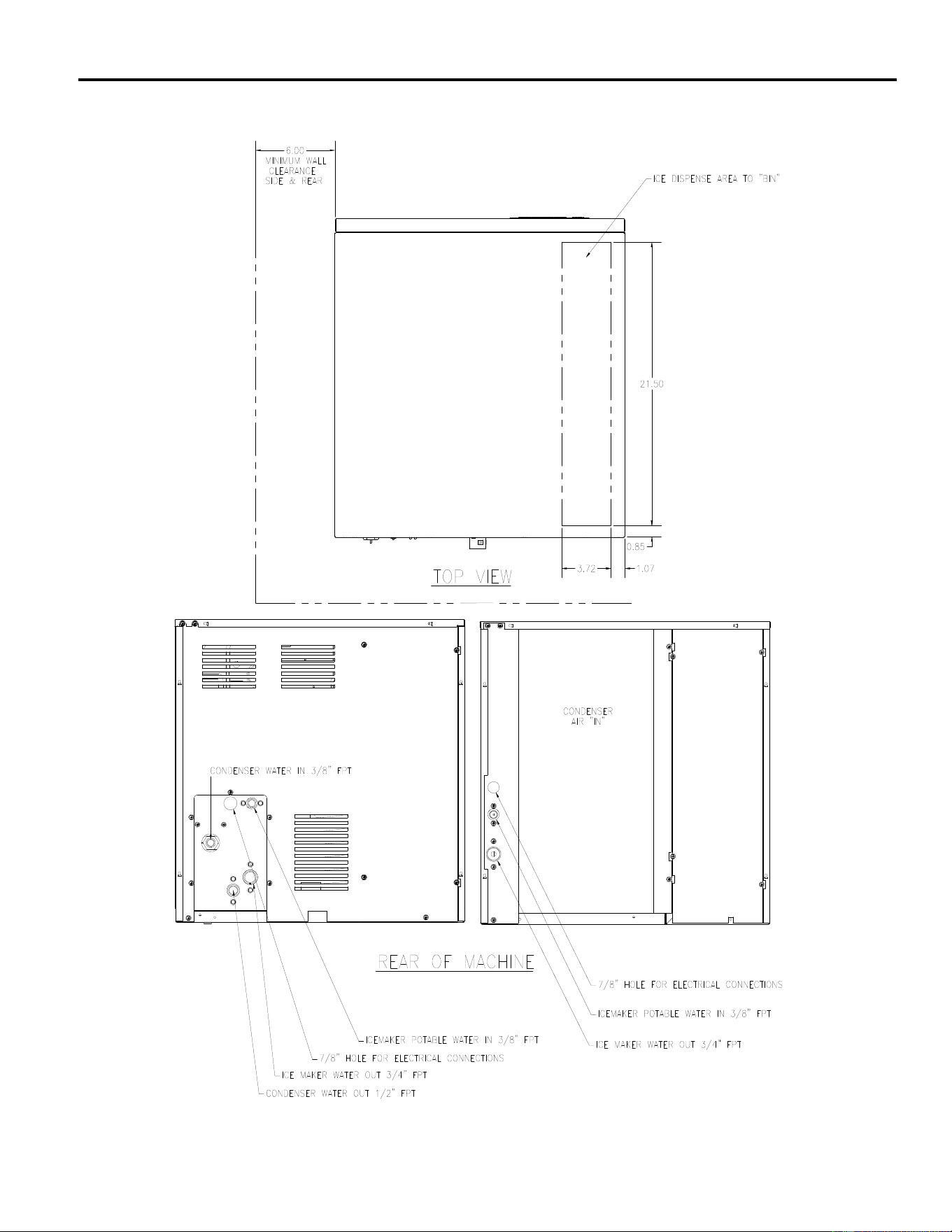
Electrical and Plumbing Requirements: ICE0320 and ICE0520 (22 Inch Wide Cubers)
ICE Series General Information
Page A12
Electrical and Plumbing Requirements: ICE1400, ICE1800 and ICE2100 Revision 3
(From January 2008)
ICE Series General Information
Page A13
Electrical and Plumbing Requirements: ICE1506 Remote
ICE Series General Information
Page A14
Electrical and Plumbing Requirements: ICE1506R5 Remote
ICE Series General Information
Page A15
Electrical and Plumbing Requirements: ICE0726 and ICE0926 Remote
ICE Series General Information
Page A16
Electrical and Plumbing Requirements: ICE1506HT Air Cooled, Top Air Discharge
Clearance Requirements for the
ICE1506HT to insure proper air circulation.
Top 8 inches
Back 6 inches
Sides 2 inches
ICE Series General Information
Page A17
Remote Condenser Installation
For proper operation of the Ice-O-Matic ice machine, the following installation guidelines must be
followed. Failure to do so may result in loss of production capacity, premature part failure, and
may void all warranties.
Installation Guidelines (Pre VRC Models)
Ambient operating temperatures: -20°F (-28.9°C) to 120°F (48.9°C)
Maximum refrigerant line length: 60 ft. (18.29 Meters)
Maximum vertical rise: 16 ft. (4.88 Meters)
Minimum condenser height: ICE Series ice machine remote condensers must not be
installed more than 6 feet (1.3 meters) below the refrigerant line quick connects at the rear of the
ice machine. No part of the refrigerant lines, between the ice machine and the remote
condenser, should fall below this point. Condensers must have a vertical airflow.
Note: Remote models with the mixing valve installed in the ice machine with sixty (60) foot lineset runs will
need an additional fifteen (15) ounces of refrigerant added.
Air Flow
ICE Series General Information
Page A18
The following remote ice makers incorporate the mixing valve in the condenser. This configuration allows
up to a 100 foot calculated remote line set run. Reference the diagram below to calculate the maximum 100
foot line set run. Maximum actual line set run is limited to 100 ft. Add ¼ ounce of refrigerant for each
actual foot from 75 feet to 100 feet actual lineset run.
ICE Machine Model Number Remote Condenser Model Number
ICE2100R3&4 & 5 VRC5061B
ICE1800R3&4 & 5 VRC5061B
ICE1400R3&4 & 5 VRC2661B
ICE1506HR2&3&4 VRC2661B
ICE1006R3&4&5 VRC2061B
ICE0926 VRC2061B
ICE0806R3&4 &5 VRC2061B
ICE0726 VRC2061B
ICE0606R3&4&5&6 VRC1061B
ICE0500R3&4 &5 VRC1001B
Limitations for new remote machines that have the mixing valve mounted in the condenser.
Maximum Rise is 35 feet.
Maximum Drop is 15 feet.
Maximum equivalent run is 100 feet.
Formula for figuring maximum equivalent run is as follows:
Rise x 1.7 + Drop x 6.6 + horizontal run = equivalent run.
Examples: 35 ft. rise x 1.7 + 40 ft. horizontal = 99.5 equivalent feet line run
35 ft. rise
40 ft. horizontal
10 ft. drop x 6.6 + 34 ft horizontal = 100
equivalent feet line run
10 ft. dro
p
34 ft. horizontal
Verify the ICE machine is compatible with the remote
condenser. Some ice machines and some remote
condensers may or may not have a Mixing Valve (Head
Master). Only one valve is required per system. Kits are
available to modify the condenser for compatibility. For
more information contact your Ice-O-Matic Distributor.

ICE Series General Information
Page A19
How the ICE Machine Works
A general description of how the ICE Series cubers work is given below. The remainder of the
manual provides more detail about the components and systems.
With the ICE/OFF/WASH switch in the ICE position, the compressor, water pump and condenser
fan motor (when applicable) will energize starting the freeze cycle.
During the freeze cycle, water is circulated over the evaporator(s) where the ice cubes are formed.
When the suction pressure has pulled down to the proper cut-in pressure of the timer initiate
(pressure control), the contacts will close and energize the time delay module (timer). See Page
F3 for proper cut-in pressures. At this time the cubes will close to completion.
The remaining portion of the freeze cycle is determined by the timer setting. The timer is pre-set at
the factory to achieve the proper ice bridge thickness but may need to be adjusted upon initial
start-up.
The factory initial timer settings are 64 and 128 for a Half Cube and 128 and 256 for a Full Cube.
Once the amount of time on the timer has passed, the control relay will be energized and the
machine will enter harvest. Power is now supplied to the water purge valve, hot gas valve, and the
harvest motor. The water purge valve opens, and allows the water pump to purge the water
remaining in the water, removing impurities and sediment. This allows the machine to produce
clear ice cubes and keep mineral build up at a minimum. The hot gas solenoid opens allowing hot
gas to go directly to the evaporator, heating the evaporator and breaking the bond between the
evaporator and the ice slab.
Note: The operation of the Hot Gas Valve and Water Pump vary by model number, reference
the wiring diagram on the specific model number for operation sequence.
The harvest assist motor, which is also energized during harvest, turns a slip clutch, which pushes
a probe against the back of the ice slab. Once the evaporator has reached approximately 40F
(4.5F) in temperature, the slip clutch overcomes the bonding of the ice to the evaporator and
pushes the slab of ice off of the evaporator and into the storage bin. The clutch also actuates a
switch that rides on the outer edge of the clutch. When the clutch completes one revolution, the
switch is tripped and the machine enters the next freeze cycle.
Note: Units produced from July of 2015 utilize an improved drive motor which eliminated
the clutch assembly.
When ice drops into a full bin during harvest, the splash curtain is held open which activates a bin
switch shutting the machine off. When ice is removed from the bin, the splash curtain will close
and the machine will come back on.
ICE Series General Information
Page A20
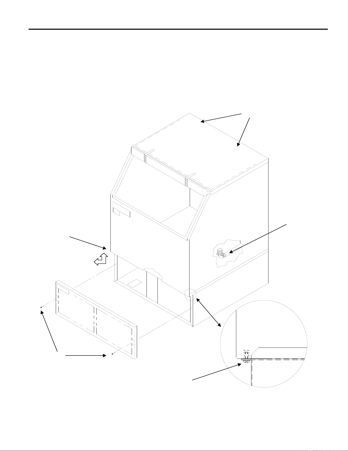
Undercounter Bin Removal-ICEU300/305 and ICEU150-220/225/226 (From 6/08) Series
The storage bin can be removed by:
1 Remove the lower grill.
2. Remove two screws securing bin to cabinet base.
3. Remove the thumbscrews from the back wall of the bin.
4. Disconnect bin drain.
5. Lift front of bin slightly and pull bin forward to remove.
1
2
3
ICE Series General Information
Page A21
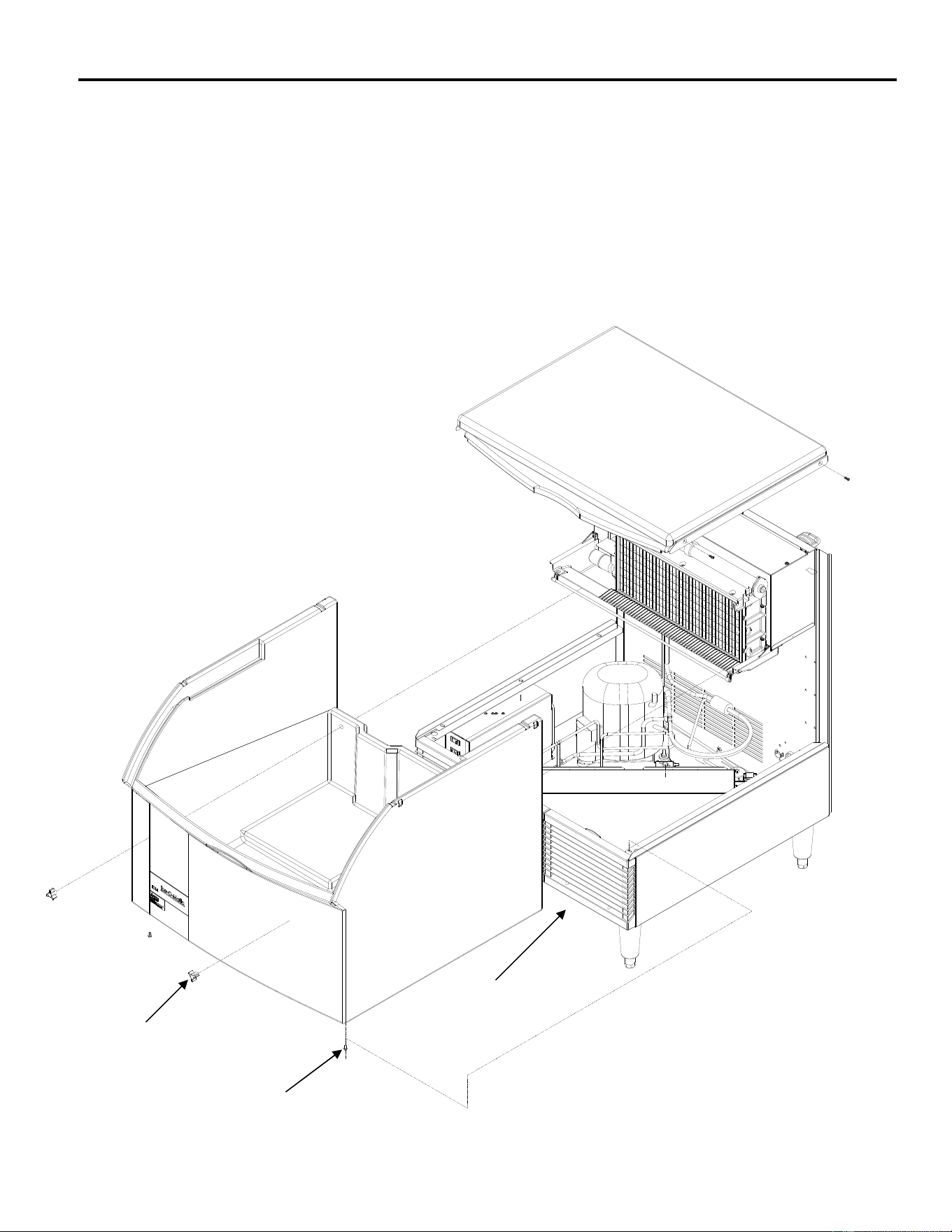
Undercounter Bin Removal-ICEU150/200/220/225/226 Series (Prior to 6/08)
The storage bin can be removed by:
1. Remove the two screws at the rear of the top panel.
2. Remove the two screws from the front panel.
3. Remove two screws securing bin to cabinet base.
4. Disconnect bin drain.
5. Lift front of bin slightly and pull bin forward to remove.
1
2
3
4
5

ICE Series General Information
Page A22
Warranty Information
Every Ice-O-Matic machine is backed by a warranty that provides both parts and labor coverage.
Cube Ice Makers – ICE Series
Three years Parts and Labor.
Five years Parts coverage on the evaporator and the compressor.
Seven years Parts and Labor on the evaporator when you purchase an Ice-O-Matic water filter
with your cube ice maker and replace the filter every 6 months AND register it on our website
(available in the U.S. and Canada only).
Warranty If, during the warranty period, customer uses a part for this Ice-O-Matic equipment other
than an unmodified new part purchased directly from Ice-O-Matic, Ice-O-Matic Distributors, or any
of its authorized service agents and/or the part being used is modified from its original
configuration, this warranty will be void. Further, Ice-O-Matic and its affiliates will not be liable for
any claims, damages or expenses incurred by customer which arises directly or indirectly, in whole
or in part, due to the installation of any modified part and/or part received from an unauthorized
service center. Adjustments are not covered under warranty.
Warranty Procedure If the customer is using a part that results in a voided warranty and an
Ice-O-Matic authorized representative travels to the installation address to perform warranty
service, the service representative will advise customer the warranty is void. Such service call will
be billed to the customer at the authorized service center’s then-applicable time and material rates.
Ice-O-Matic Warranty
Every Ice-O-Matic ice maker is backed by a warranty that provides both parts and labor coverage.
To view the warranty details, register products, or check your warranty status visit the “Warranty
and Water Filter Registration” page on www.iceomatic.com

ICE Series Scheduled Maintenance
Page B1
Maintenance
Note: Maintenance should be performed by an Ice-O-Matic trained Service Technician.
Electrical shock and/or injury from moving parts inside this
machine can cause serious injury. Disconnect electrical
supply to machine prior to performing any adjustments or
repairs.
Failure to perform the required maintenance at the frequency specified will void warranty coverage
in the event of a related failure. To insure economical, trouble free operation of the machine, the
following maintenance is required every 6 months.
Maintenance Procedure
1. Clean the ice-making section per the instructions below. Cleaning should be performed a
minimum of every 6 months. Local water conditions may require that cleaning be performed more
often.
2. Check ice bridge thickness. See page F4 for proper thickness and adjustment procedure.
3. Check water level in trough. See page D1 for proper water level and adjustment.
4. Clean the condenser (air-cooled machines) to insure unobstructed air flow.
5. Check for leaks of any kind: Water, Refrigerant, Oil, Etc.
6. Check the bin switch for proper adjustment. See page F9 for bin switch adjustment.
7. Check the cam switch adjustment. See page F8 for cam switch adjustment.
8. Check the water valve (water-cooled machines) for proper adjustment. See page E2.
9. Check all electrical connection.
10. Oil the fan motor if the motor has an oil fitting. (Self contained air-cooled models only)

ICE Series Cleaning/Sanitizing Procedures
Page B2
ICE Machine and/or Bin/Dispenser Cleaning and Sanitizing Instructions
Cleaning should be scheduled at a minimum of twice per year.
Sanitizing should be performed after each cleaning or more frequently as required.
Note: Electrical power will be ON when performing the following cleaning instructions.
The cleaning and sanitizing of any commercial ice machine are important procedures all operators need to have in
their preventive maintenance protocol. While similar, these two procedures are uniquely different and accomplish
different things. Cleaning or de-liming, dissolves the mineral deposits on the evaporator and removes scale, calcium
and other mineral buildup. Sanitizing disinfects the machine and removes microbial growth including mold and slime.
In either case, it is important to use solutions that do not harm the ice machine. Never use cleaning or sanitizing
solutions that contain Nitric Acid, Sulfuric Acid, Hydrochloric Acid, Carbolic Acid, Acetic Acid, diluted Acetic Acid or
non-food-grade vinegar (concentration of acetic acid greater than 6% and does not contain enzymes created in
processing) or any chlorine-based solution such as bleach, chlorine dioxide or any type of salts such as potassium
chloride (potassium salts) or sodium chloride. Check the label or the manufacturer’s Material Safety Data Sheet
(MSDS) to be sure. These chemicals can attack the surface of the evaporator as well as other metal components
causing corrosion and flaking. Reverse Osmosis (RO) water can be very acidic and can attack the evaporator and
other metal in the ice machine. Because the RO process removes all minerals and metals from the water it can
promote the faster growth of microbial, mold and slime. If RO water is used, Ice-O-Matic recommends the water pH is
verified to be a neutral 7.0 to minimize the corrosive effects. Incorrect cleaners, sanitizers, and RO water that does not
have a neutral pH could void the machine’s warranty.
Cleaning
Prior to Cleaning the ice machine and/or Bin/Dispenser, perform the following:
1. Remove the ice machine front panel.
2. Make sure that all the ice is off of the evaporator. If ice is being made, wait for cycle completion then turn the
machine “OFF” at the ICE/OFF/WASH selector switch.
3. Turn off the potable water supply to the ice machine.
4. Remove all ice in the storage bin. (Required for cleaning and/or sanitizing)
Cleaning Instructions-Ice Machine
1. Initiate the wash cycle at the ICE/OFF/WASH switch by placing the switch in the “WASH” position. Depress the
Purge Switch to flush the remaining water from the water trough. Release the Purge Switch when the water
trough is empty
2. Terminate the wash cycle at the ICE/OFF/WASH switch by placing the switch in the “OFF” position.
3. Add recommended amount of approved nickel safe ice machine cleaner (diluted per manufacturer’s instructions) to
the water trough. (Reference cleaner Manufacturer’s instructions on the package)
4. Initiate the wash cycle at the ICE/OFF/WASH switch by placing the switch in the “WASH” position. Allow the
cleaner to circulate for approximately 15 minutes to remove mineral deposits.
5. Depress the Purge Switch and hold until the ice machine cleaner has been flushed down the drain
4. Terminate the wash cycle at the ICE/OFF/WASH switch by placing the switch in the “OFF” position. Remove the
splash curtain and inspect the evaporator and water spillway to ensure all mineral residue has been removed.
5. If necessary, wipe the evaporator, spillway and other water transport surfaces with a clean soft cloth to remove any
remaining residue. If necessary, remove and clean the water trough thoroughly to remove all scale or slime build-
up, remove the water distribution tube, disassemble and clean with a bottlebrush. Reassemble all components and
repeat steps 2 through 5 as required to remove any remaining residue.
7. Sanitizing the Ice Machine is required after cleaning per Sanitizing Instructions
Cleaning Instructions-Storage Bin/ Dispenser
1. Open the bin door and remove all of the ice in the storage bin, store the ice in a clean container for reuse or discard.
2. Add recommended amount of approved nickel safe ice machine cleaner (diluted per manufacturer’s instructions)
(Reference cleaner Manufacturer’s instructions on the package)
3. Thoroughly wash all surfaces within the bin, this includes the bin door, bin walls, window track and snout area with
soap and water and rinse. Note: An extended handle soft bristle brush may be required.
4. Allow the mineral deposits to absorb the cleaner for approximately 15 minutes to remove and loosen the mineral
deposits. Note: This includes the bin drain.
5. Thoroughly wash all surfaces within the bin, this includes the bin door, bin walls, window track and snout area with
soap and water and rinse. Note: Repeat Steps 3, 4 and 5 as required.
6. Sanitizing the Storage Bin/Dispenser is required after cleaning per Sanitizing Instructions.
ICE Series Cleaning/Sanitizing Procedures
Page B3
Sanitizing
Prior to Sanitizing the ice machine and/or Bin/Dispenser, perform the following:
1. Remove the ice machine front panel.
2. Make sure that all the ice is off of the evaporator. If ice is being made, wait for cycle completion then turn the
machine “OFF” at the ICE/OFF/WASH selector switch.
3. Turn OFF the potable water supply to the ice machine.
4. Remove all ice in the storage bin. (Required for cleaning and/or sanitizing)
Sanitizing Instructions-Ice Machine
1. Use an EPA approved food equipment sanitizer at the solution mix recommended by the sanitizer manufacturer.
2. Add enough sanitizing solution to fill the water trough to overflowing and place the ICE/OFF/WASH switch to the
“WASH” position and allow circulation to occur for 10 minutes and inspect water transport system for water leaks.
During this time, wipe down all other ice machine splash areas. Inspect to insure that water transport system
components are in the correct position.
3. Depress the Purge Switch and hold until sanitizer has been flushed down the drain. Turn ON the ice machine
potable water supply and to flush the remaining diluted sanitizing solution out of the water trough for another 1 to 2
minutes.
4 Place the ICE/OFF/WASH switch to the “ICE” position and replace the front panel.
5. Discard the first two ice harvests. DO NOT USE any ice produced from the cleaning solution.
Sanitizing Instructions- Bin/ Dispenser
1. Use an EPA approved food equipment sanitizer at the solution mix recommended by the sanitizer manufacturer.
2. Sanitize the bin interior, this includes the bin door, bin walls, window track and snout area with an approved sanitizer
using the directions for that sanitizer. Note: This includes the bin drain.
3. Discard the first two ice harvests. DO NOT USE any ice produced from the cleaning solution.
Common Questions
•Ice-O-Matic Ice Machine/Bin Cleaning
Cleaning or de-liming an ice machine refers to the process of removing mineral buildup and scale from the evaporator
and other components. Ice-O-Matic recommends cleaning the ice machine at least every 6 months. More frequent
cleaning may be needed depending on water quality and filtration system used. It is the responsibility of the operator to
determine the optimal frequency for their particular environment. Cleaning will not remove microbial, mold, or slime.
The machine should always be sanitized after cleaning.
Ice-O-Matic recommends a “nickel-safe” cleaner such as Nu-Calgon or equivalent. Typically the chemical composition
is as follows:
Water 53% to 82%
Phosphoric Acid 15% to 40%
Citric Acid 3% to 7%
Ice-O-Matic recommends cleaning be done by a trained technician and that they follow detailed steps as prescribed in
the Technical Service Manual.
Most cleaners list in their instructions an ounces to a gallon mixture for proper level of solution. Pouring undiluted
cleaner directly into the water trough may not give proper dilution level. Ice-O-Matic recommends mixing in a plastic
container before pouring into trough.
•Ice-O-Matic Ice Machine/Bin/Dispenser Sanitizing
Ice-O-Matic recommends sanitizing or disinfecting an ice maker a minimum of every six months. More frequent
sanitizing may be needed if the machine is in a high yeast environment or if RO water is being used. It is the
responsibility of the operator to determine the optimal frequency for their particular environment.
Ice-O-Matic recommends an EPA approved sanitizer such as Nu-Calgon IMS-II or equivalent. Sanitizing is a simple
matter of running the EPA approved sanitizer through the ice machine/bin/dispenser and wiping down surfaces with
the sanitizer.
If being done at the same time as the cleaning process, sanitizing must be done after the cleaning process. Follow the
process as prescribed in the Owner’s Manual.
Note: this process requires the ice be removed from the bin.
Ice Machine Cleaner contains acids.
KEEP OUT OF THE REACH OF CHILDREN
Refer to ice machine cleaner manufactures emergency
instructions on container label.
ICE Series Winterizing Procedures
Page B4
Winterizing Procedures
Important!
Whenever the ice machine is taken out of operation during the winter months, the procedure below
must be performed. Failure to do so may cause serious damage and will void all warranties.
1. Turn off water to machine.
2. Make sure all ice is off of the evaporator(s). If ice is being made, initiate harvest or wait for
cycle completion.
3. Place the ICE/OFF/WASH switch to the “OFF” position.
4. Disconnect the tubing between the water pump discharge and water distribution tube.
5. Drain the water system completely.
6. On water cooled machines, hold the water regulating valve
open by prying upward on the water valve spring with a
screwdriver while using compressed air to blow all the water out
of the condenser.
7. Remove all of the ice in the storage bin and discard.

ICE Series Cabinet Care
Page B5
Cleaning Stainless Steel and Aluminum
Commercial grades of stainless steel and aluminum are susceptible to rusting and corrosion if not properly maintained.
It is important that you properly care for the stainless steel and aluminum surfaces of your ice machine and bin to avoid
the possibility of rust or corrosion. Use the following recommended guidelines for keeping your machine looking like
new:
1. Clean the stainless steel and aluminum thoroughly once a week. Clean frequently to avoid build-up of hard,
stubborn stains. Also, hard water stains left to sit can weaken the metals corrosion resistance and lead to rust or
corrosion. Use a nonabrasive cloth or sponge, working with, not across, the grain.
2. Don't use abrasive tools to clean the metal surface. Do not use steel wool, abrasive sponge pads, wire brushes
or scrapers to clean the metal.
3. Don't use cleaners that use chlorine or chlorides. Do not use chlorine bleach products to clean the metal
surfaces. Chlorides break down the metals protective layer.
4. Rinse with clean water. If chlorinated cleansers are used, you must thoroughly rinse the surface with clean water
and wipe dry immediately.
5. Use the right cleaning agent. The table below lists the recommended cleaning agents for common metal cleaning
problems:
Cleaning Activity Cleaning Agent Method of Application
Routine cleaning Mild dish Soap, Ammonia, Glass Apply with a clean cloth
Cleaner, or mild detergent with water. or sponge. Rinse with
Household Kitchen clean water and wipe dry.
Cleaning chemicals approved
For metal surfaces
Removing grease or Oven cleaners. Apply generously, allow
fatty acids to stand for 15-20 minutes.
Rinse with clean water.
Repeat as required.
Removing hard water spots Vinegar Swab or wipe with clean cloth.
and scale. Rinse with clean water and dry.

ICE Series Troubleshooting Trees
Page C1
How To Use The Troubleshooting Trees
The troubleshooting trees were developed to be used in conjunction with the service information in
the sections that follow. If used together as intended, these two parts of the manual will allow the
ice machine service technician to quickly diagnose many of the problems encountered with the ice
machines. When used as designed, the troubleshooting trees can lead you from a general
symptom to the most likely component to suspect as the cause of the problem. The trees are not
designed to be “parts changer guides”: please do not use them as such.
Components returned to the factory for warranty are tested by the factory and will not be covered
under the warranty policy if they are not defective.
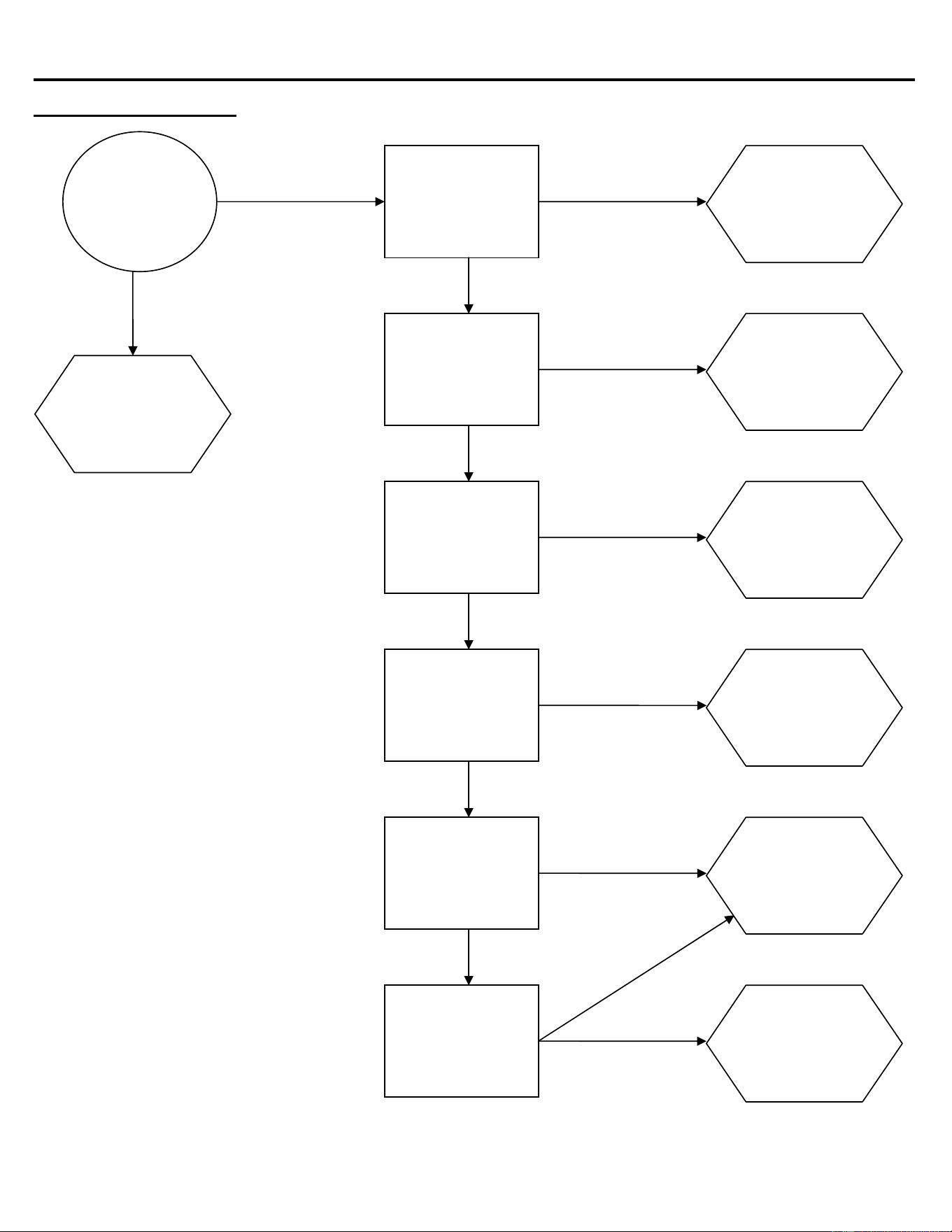
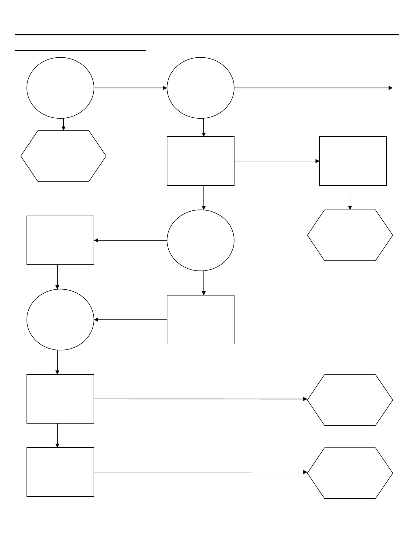
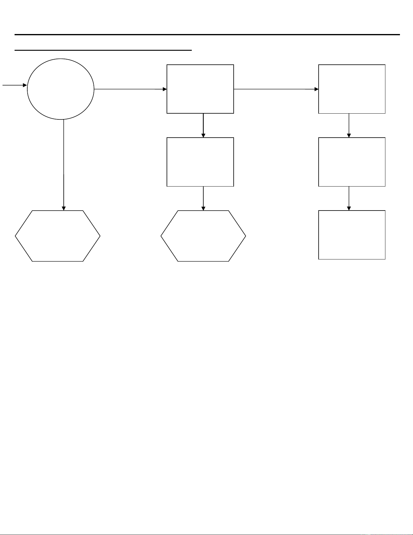
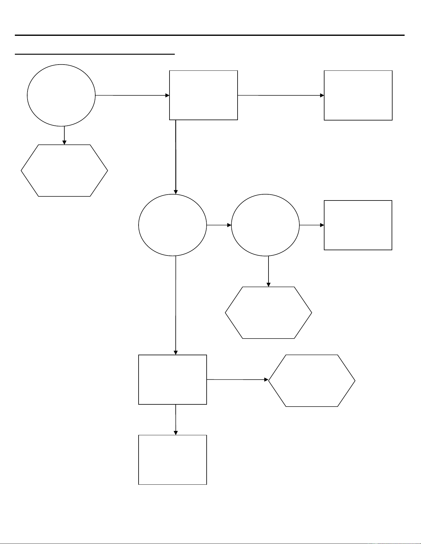
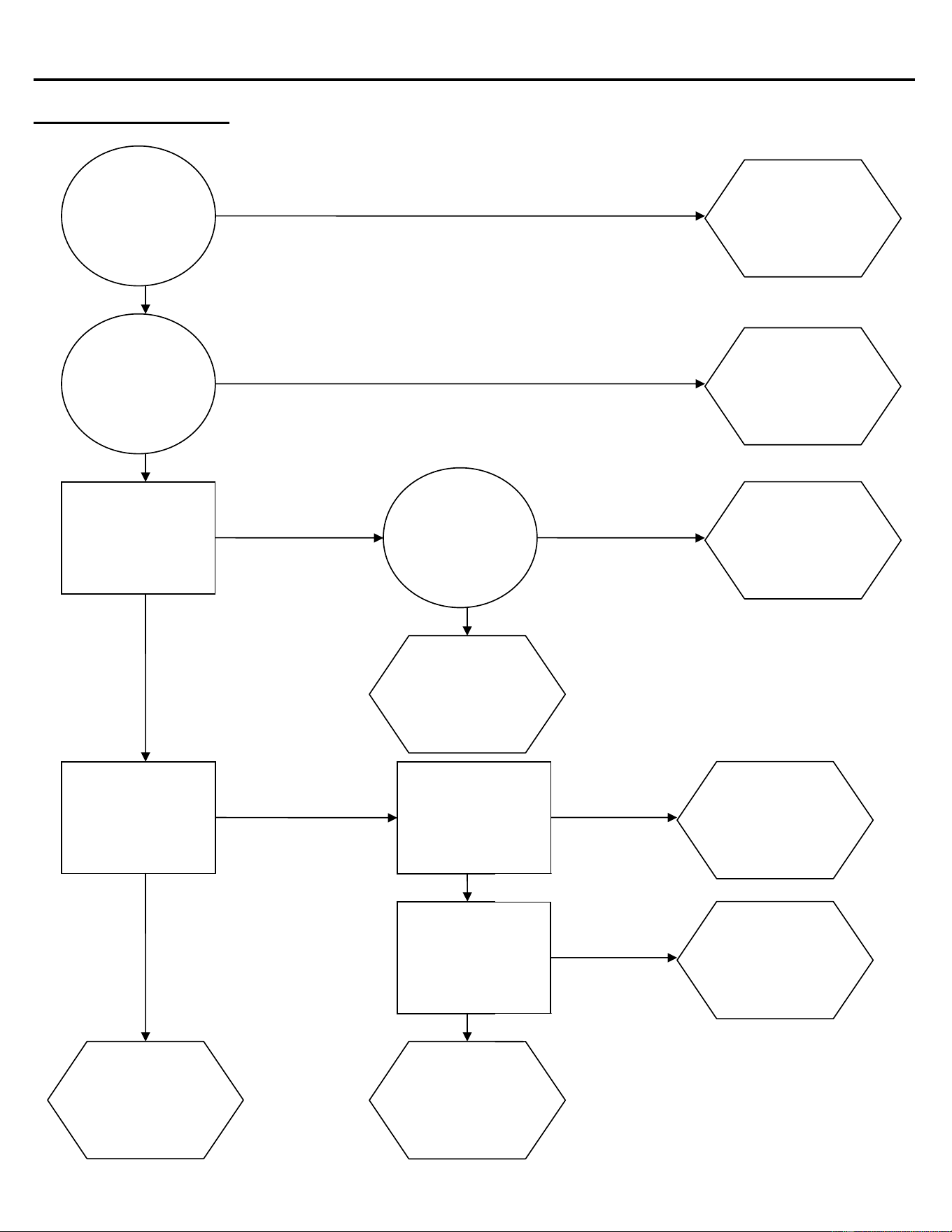
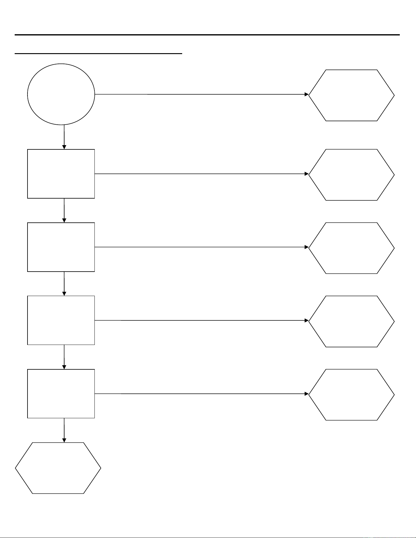
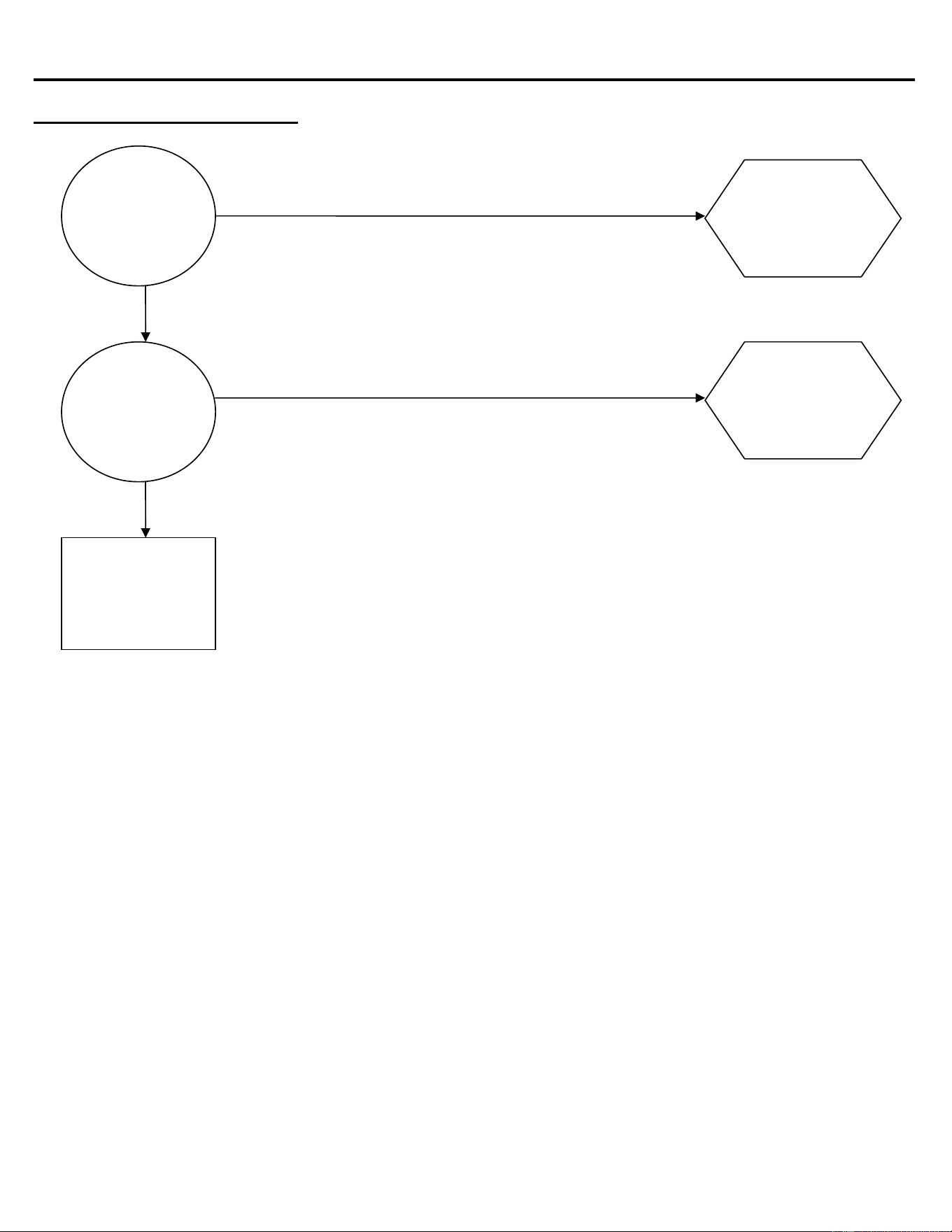
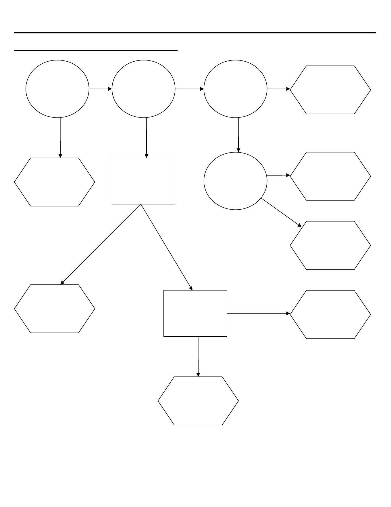
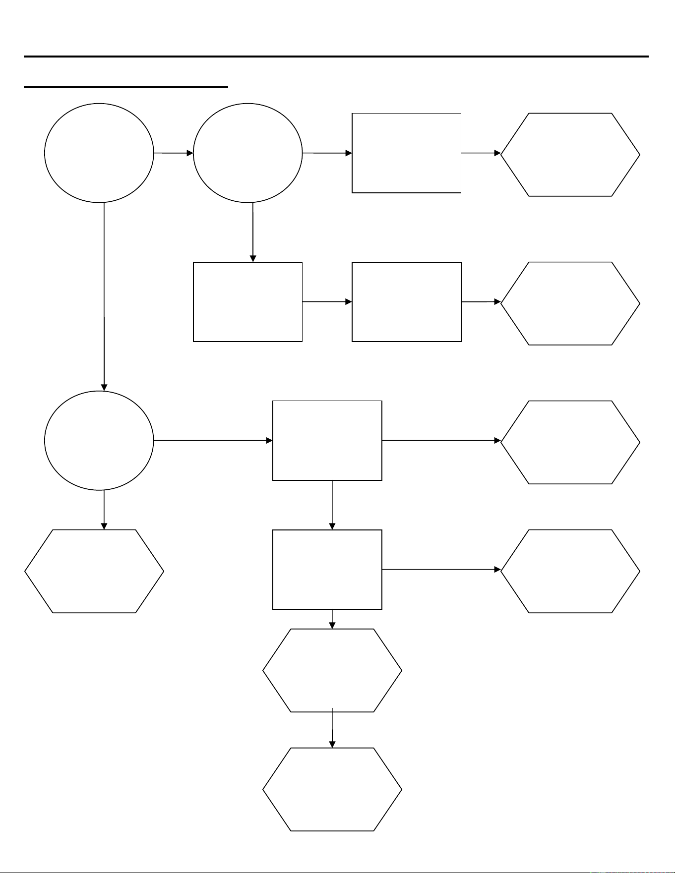
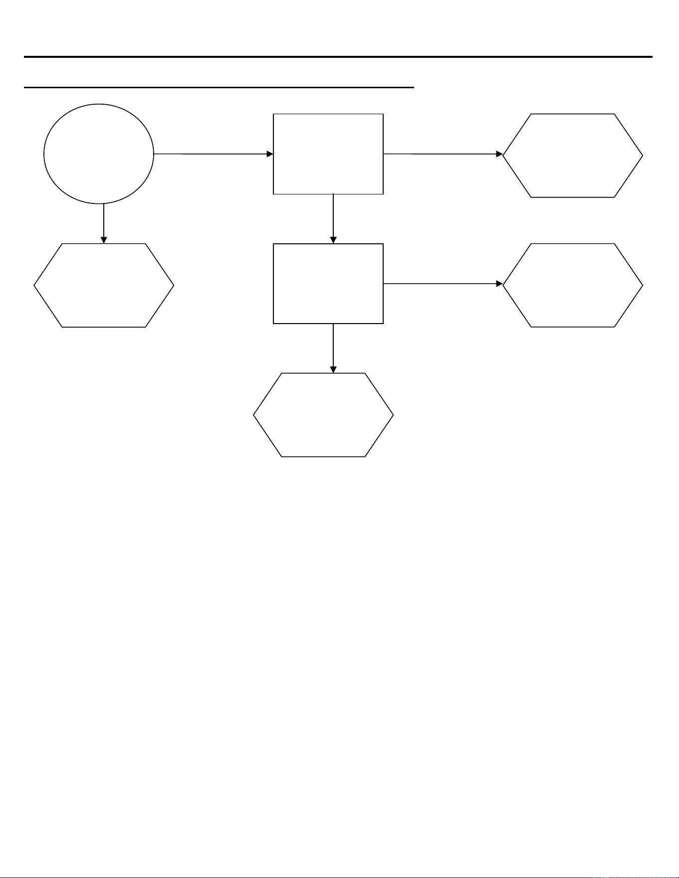
The troubleshooting trees are made of three types of boxes:
?
!
9
QUESTION boxes (Circle) ask a yes/no question and the answer will lead to either another
question box, a check box or a solution box.
CHECK boxes (Rectangle) will suggest a point to check for proper operation, and will often refer
you to a page in the service information sections of this manual. The result of the check may lead
to another box, or a solution box.
SOLUTION boxes (Hexagon) suggest the most likely component to cause the malfunction
described in the heading of the tree. When reaching a solution box, DO NOT immediately assume
the component is defective. The final step is to verify that the component is indeed defective, by
using the service information in the sections that follow.
To use the troubleshooting trees, first find the page with the heading describing the type of
problem occurring. Begin at the top of the page and follow the tree, step-by-step. When a check
box is reached, it may be necessary to refer to another section in the manual.
Once a solution box is reached, refer to the appropriate section to verify that the component in the
solution box is, indeed, the problem. Adjust, repair or replace the component as necessary.

ICE Series Troubleshooting Trees
Page C2
Troubleshooting Trees Table Of Contents
Machine Does Not Run C3
Machine Runs, Does Not Make Ice C4 – C5
Slow Production (Cube Formation Good) C6
Low Suction Pressure C7
High Suction Pressure C8
Cubes Are Hollow C9
Uneven Bridge Thickness C10
Ice Bridge Thickness Varies Cycle To Cycle C11
Machine Produces Cloudy Ice C12
Poor Water Distribution Over Evaporator C13
Machine Does Not Enter Harvest C14
Machine Enters Harvest, Then Returns To Freeze Prematurely C15
Length Of Harvest Excessive C16
Ice Does Not Release From Evaporator C17
Hot Evaporator, Low Suction Pressure (Remote Only) C18
ICE Series Troubleshooting Trees
Page C3
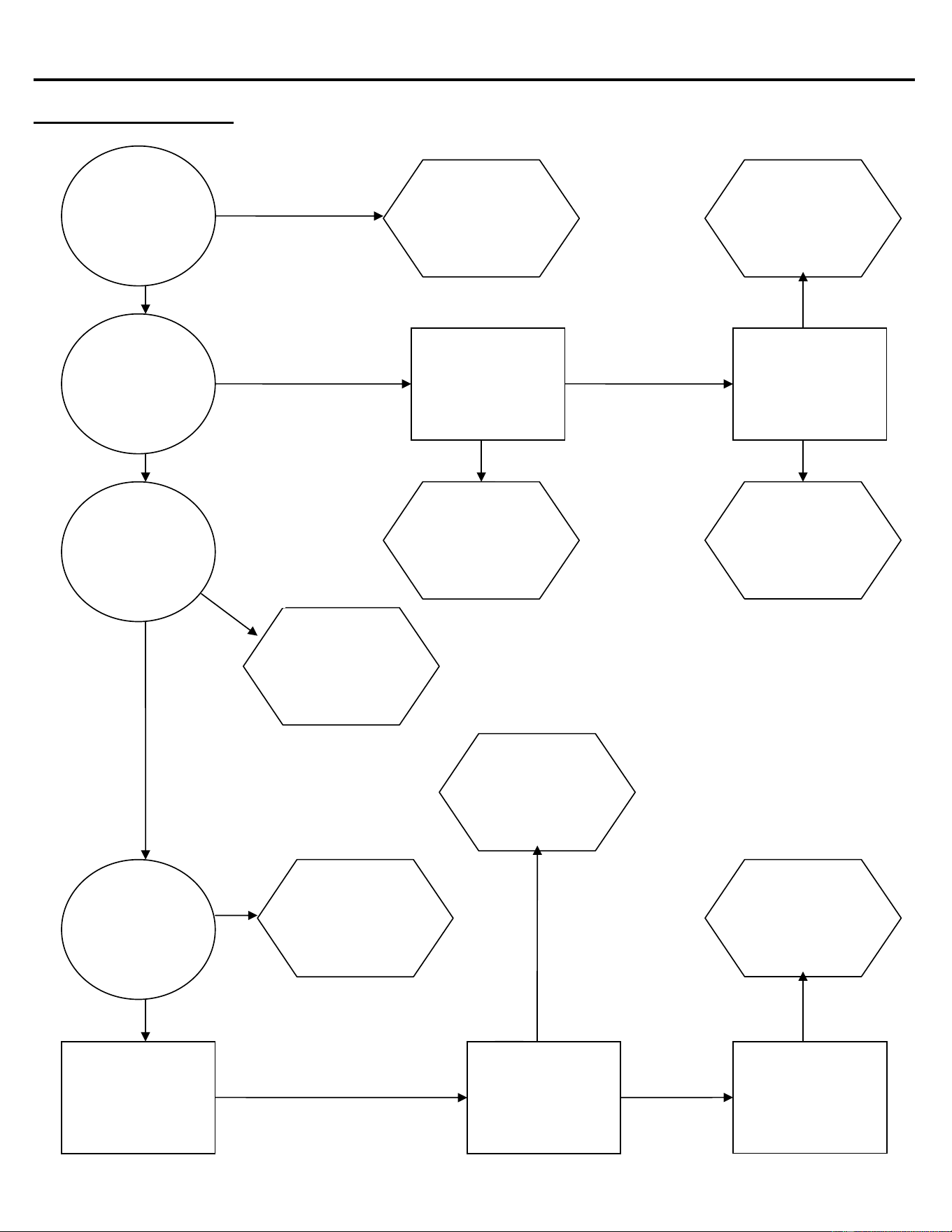
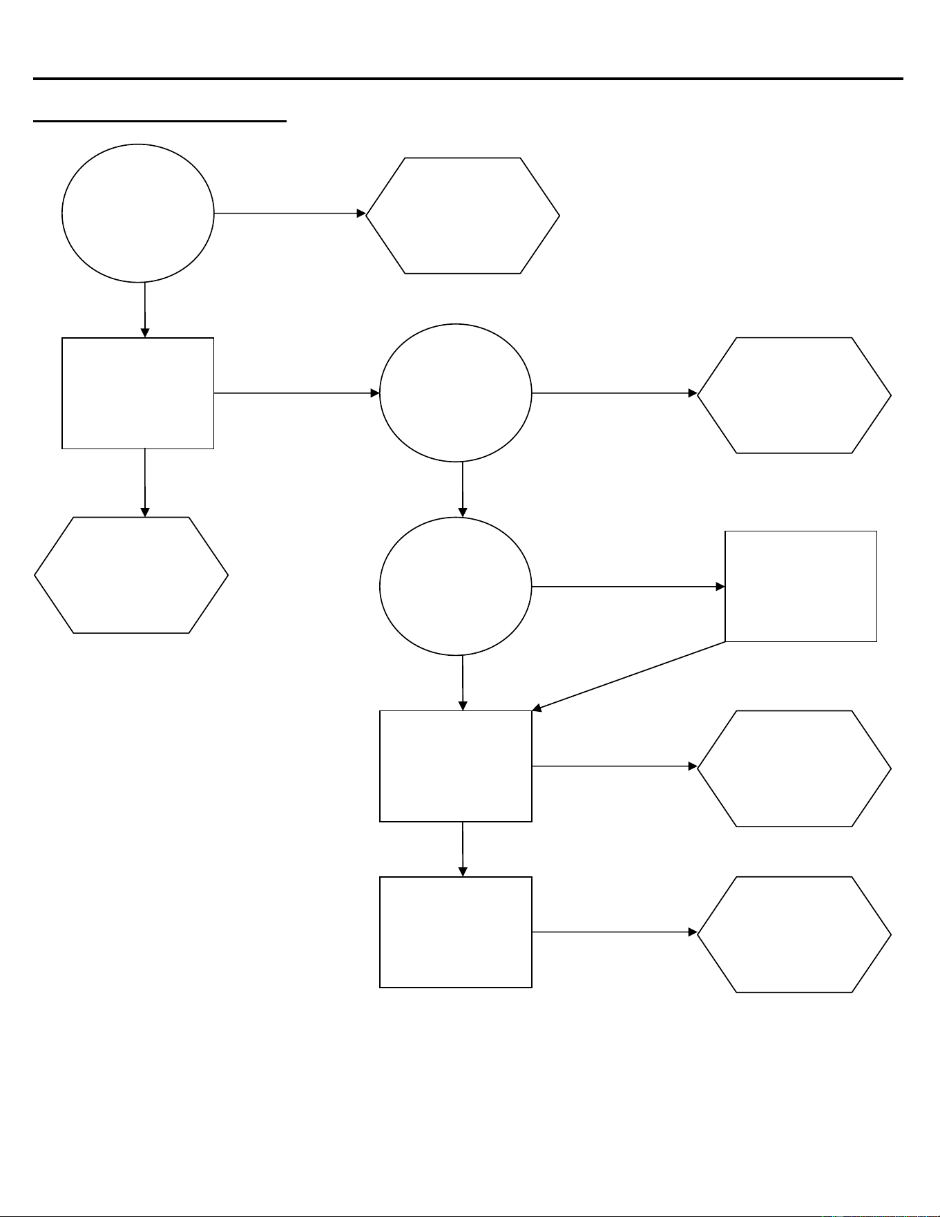
Machine Does Not Run
Check for correct
power supply to the
machine
YES NOT OK
NO
OK
Is the selector
switch set to
ICE?
Check High
Pressure Safety
Control
Check High
Temperature Safety
Control
OK
Check Bin Control
for proper
adjustment, see
page F9
Is this a Remote
unit?
Is the Liquid line
Solenoid energized
and open?
OK
OK
GOOD
TRIPPED
OPEN
BAD
NO
NOT O
K
O
K
Adjust as
required or
replace if
defective
Replace or
identify reason
for being open.
Reset and
identify reason
for high head
pressure
Correct field
wiring deficiency
Set selector
Switch to the
ICE position
Selector Switch
could be
defective, see
page F1
Find reason for
non-activity or
replace if
defective
ICE Series Troubleshooting Trees
Page C4
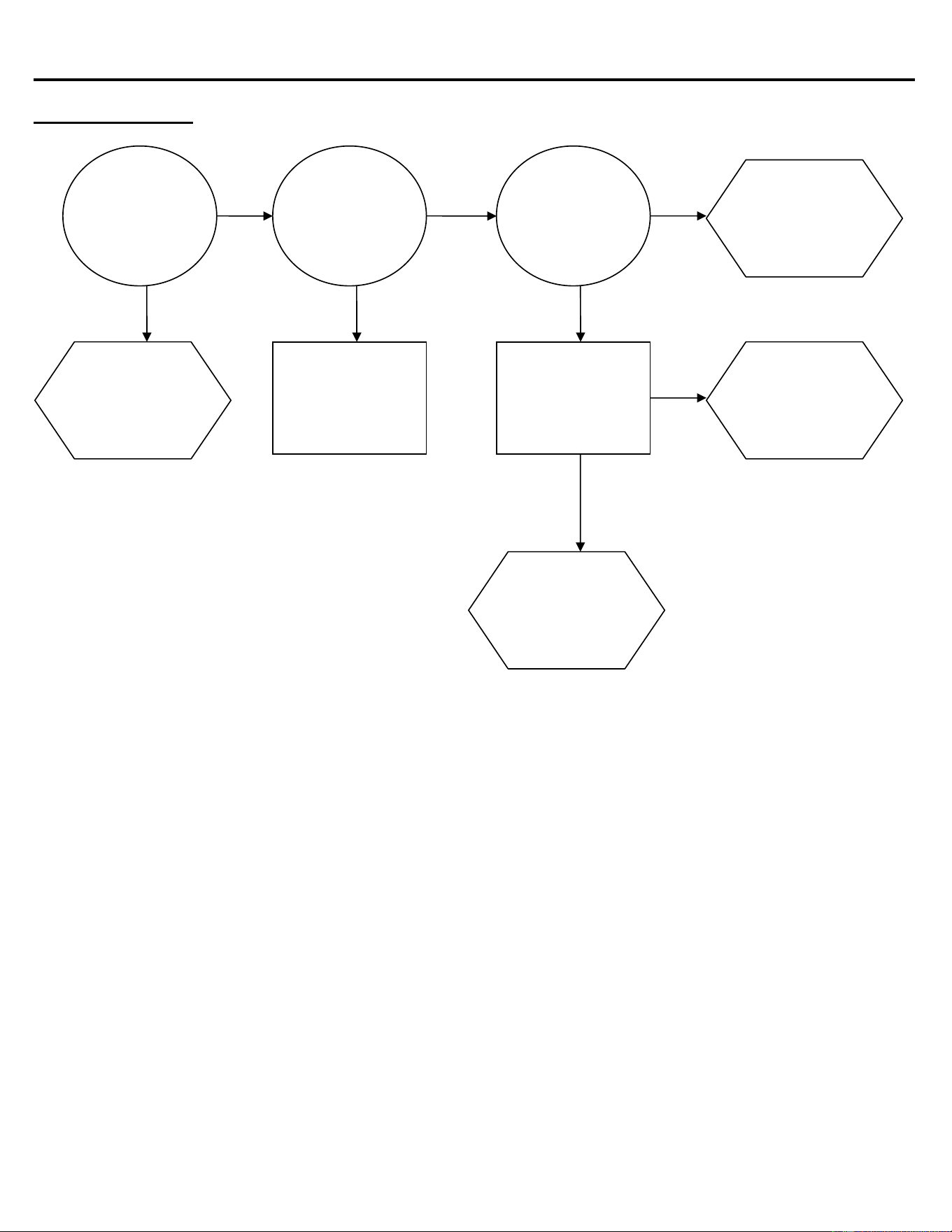
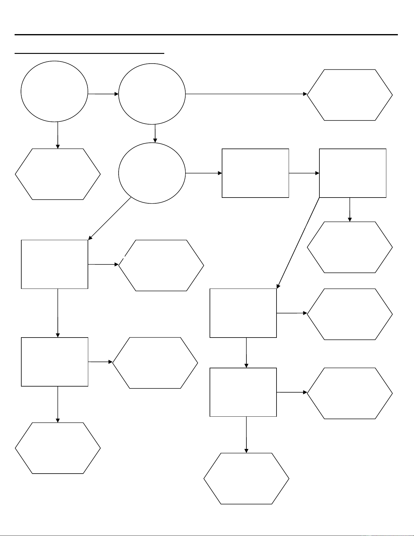
Machine Runs, Does Not Make Ice
YES GO TO PAGE C5
NO
YES
Is water
running over
the
evaporator?
Check for power to
the compressor
contactor coil
Check contactor for
bad contactor or coil.
Replace if defective
Is the
compressor
running?
NO
GOOD
OK
Check Selector
Switch,
Replace if defective
Check the suction
pressure, is it low or
high?
NO
OK
HIGH
LOW
O
K
O
K
Does the unit
have a remote
condenser?
Check High
Pressure reset if
necessary
Continue if the
machine has a
remote
condenser
Check refrigerant
charge
OK
Compressor or
Start
Components
could be
defective, see
page F2
Pumpdown
Control possibly
bad
Liquid Line
Solenoid not
opening
Go to the
Troubleshooting
Tree on page
C12
ICE Series Troubleshooting Trees
Page C5
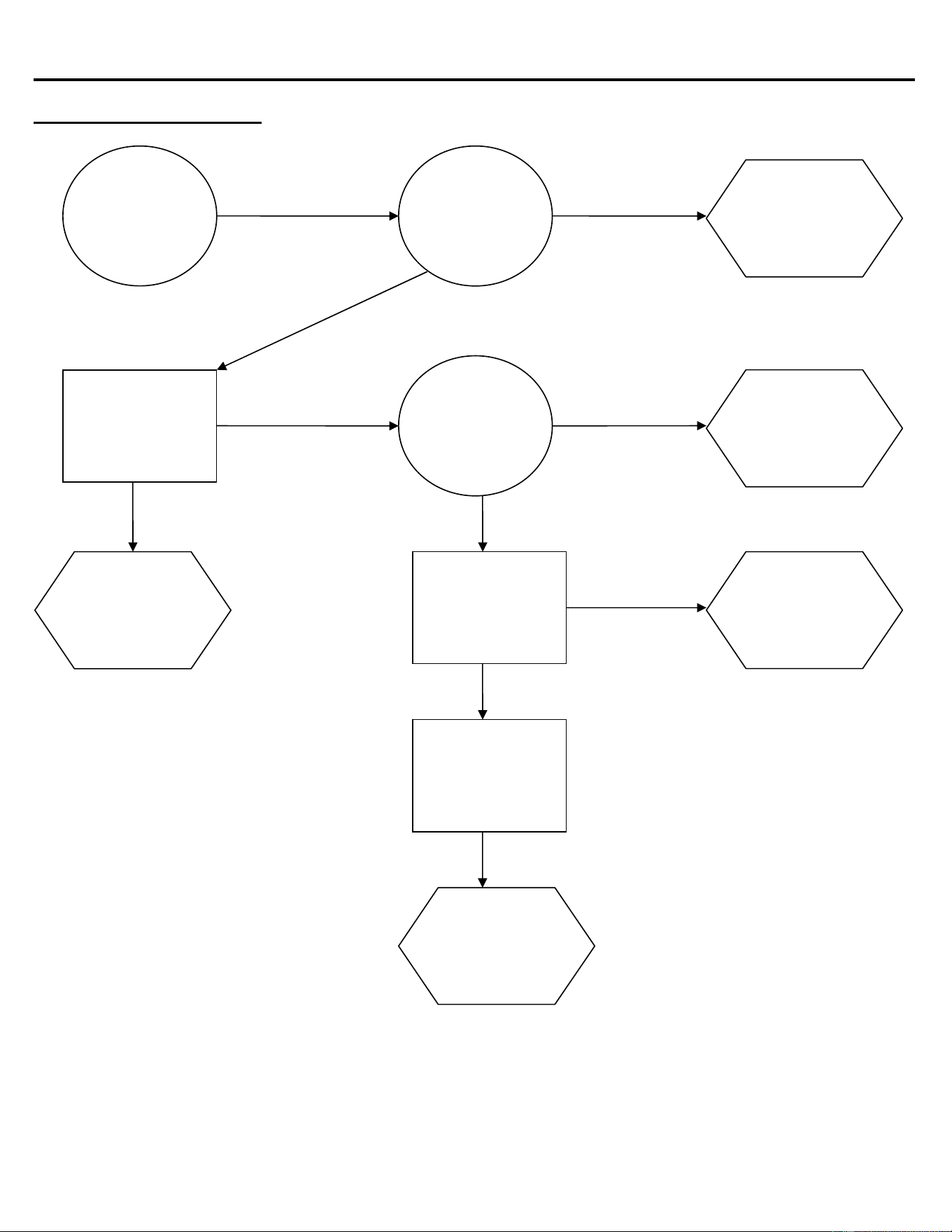
Machine Runs, Does Not Make Ice (continued)
HIGH OR NORMAL
SUCTION
Check refrigerant
pressures, see page
E1
If head pressure is
also high, make sure
Condenser is clean
and machine has
good air flow
Is water
leaking out of
the Purge
Drain or Water
Trough?
NO
YES
OK
LOW SUCTION OK
Recover and weigh
in refrigerant charge
Check Hot Gas
Valve for leakage
during freeze, see
page E5
Check for inefficient
Compressor
OK
Low side
restriction or
defective TXV
Repair water
leakage defect
ICE Series Troubleshooting Trees
Page C6
Slow Production (Cube Formation Good)
NO
YES
Does
installation
meet
guidelines?
Check refrigeration
system, Section E
Check for excessive
head pressure
OK
Check Water
Regulating Valve,
See page E2
Check refrigeration
system, Section E
AIR
YES
TOO HIGH
Clean
Condenser and
Condenser Fan
Blade
Correct any
installation
defects
Is this unit air
cooled or
water cooled?
Is the Air
Condenser
clean?
See Condenser
service information
page E2
Adjust or
replace Water
Regulating
Valve
NO
WATER
NOT OK
O
K
ICE Series Troubleshooting Trees
Page C7
Low Suction Pressure
NO
YES
Does
installation
meet
guidelines?
Check TXV for
moisture based
restriction
Check for correct
head pressure, see
page E10
NO
Check for refrigerant
tubing restriction,
crimps, etc.
Check Evaporator
coil separation, see
page E4
YES
YES
Go to
Troubleshooting
Tree on page
C12
Is the
machine a
remote unit?
Replace drier,
evacuate and
recharge
system
NO
NOT O
K
OK
Is the water
flow over the
Evaporator
correct?
Low charge,
locate and
repair leak,
evacuate and
recharge
system
See
Troubleshooting
Tree page C18
TXV possibly
defective, see
page E3 and
page E4
Correct
restricted tubing
OK
OK
WET SYSTEM
DRY SYSTEM NOT OK
NOT OK
Replace
defective
Evaporator
Correct
deficiency in
installation
ICE Series Troubleshooting Trees
Page C8
High Suction Pressure
NO
YES
Have you
checked the
“Slow
Production”
Tree?
Evacuate and
recharge system
Check Hot Gas
Valve, see page E5
NO
Check for leaking
Purge valve
Check Condenser
Fan Motor and
Blade for proper
operation, and/or
Water Valve or
Mixing Valve
YES
YES
Replace
Compressor
Go to “Slow
Production”
Troubleshooting
Tree
Is the machine
installed to
specifications?
Clean the
Condenser
NO
NOT O
K
YES
Is the head
pressure also
high?
TXV could be
defective, see
Expansion
Valve, see page
E3 and E4
Hot Gas Valve
is possibility
defective
Repair or
replace
defective part
TVX Thermal
bulb loose or
TXV could be
defective
O
K
OK
NOT OK
Check Compressor,
see page E1
NOT OK
Is the
Condenser
dirty?
Correct
installation
defects
STILL TOO
HIGH
O
K
O
K
NO
ICE Series Troubleshooting Trees
Page C9
Cubes Are Hollow
YES
Is the water
temperature
above 100°F
(38°C)?
Go to the “Poor
Water Distribution
Over Evaporator”
Troubleshooting
Tree, page C13
NO
YES
YES
Purge Valve has
an obstruction
or could be
defective
Is water
leaking from
the Purge
Drain?
NO
NOT O
K
Is there good
water flow
over the
Evaporator?
OK
Check Timer for
proper setting, see
page F4
NO
Timer Initiate
Control out of
adjustment of
defective
Timer Module
requires
adjustment or
could be
defective
Water
temperature too
high, correct
water
temperature
ICE Series Troubleshooting Trees
Page C10
Uneven Bridge Thickness
HIGH
Make sure
supply water
temperature is
below 100°F
(38°C)
Check for water
leaking out of Purge
Drain
NO
YES
YES
Problem in
water system,
see pages D1
and D2.
Dirty or
defective Purge
Valve
Is water
running into
the bin?
NO
OK
Are the
Evaporator(s)
flooded? See
page E4 and
E5
Serpentine coil
on back of
evaporator
could be
separated, see
page E4
Check the suction
pressure, is it high or
low? See pageE1
LOW
Make sure the
system is charged
properly, recover the
charge and weigh in
the correct amount
NO
Hot Gas Valve
could be
leaking, see
page E5
OK
Refer to page
E3 and E4 for
TXV diagnosis.
ICE Series Troubleshooting Trees
Page C11
Ice bridge Thickness Varies Cycle To Cycle
NOT OK
Is air and
water temps
consistent and
within
guidelines?
Check the Purge
Valve for water leaks
NO
YES
O
K
Correct
installation
deficiency
Replace Timer
Initiate
OK
Clean Purge
Valve or replace
if defective
OK
Check Hot Gas
valve for proper
operation
NOT OK
Check Timer Initiate
Control for proper
operation
Replace Hot
Gas Valve
OK
Check Solid State
Timer for proper
operation
NOT OK
Adjust Timer or
replace if
defective
NOT OK
TXV(s) could be
defective, see
page E3 and E4
ICE Series Troubleshooting Trees
Page C12
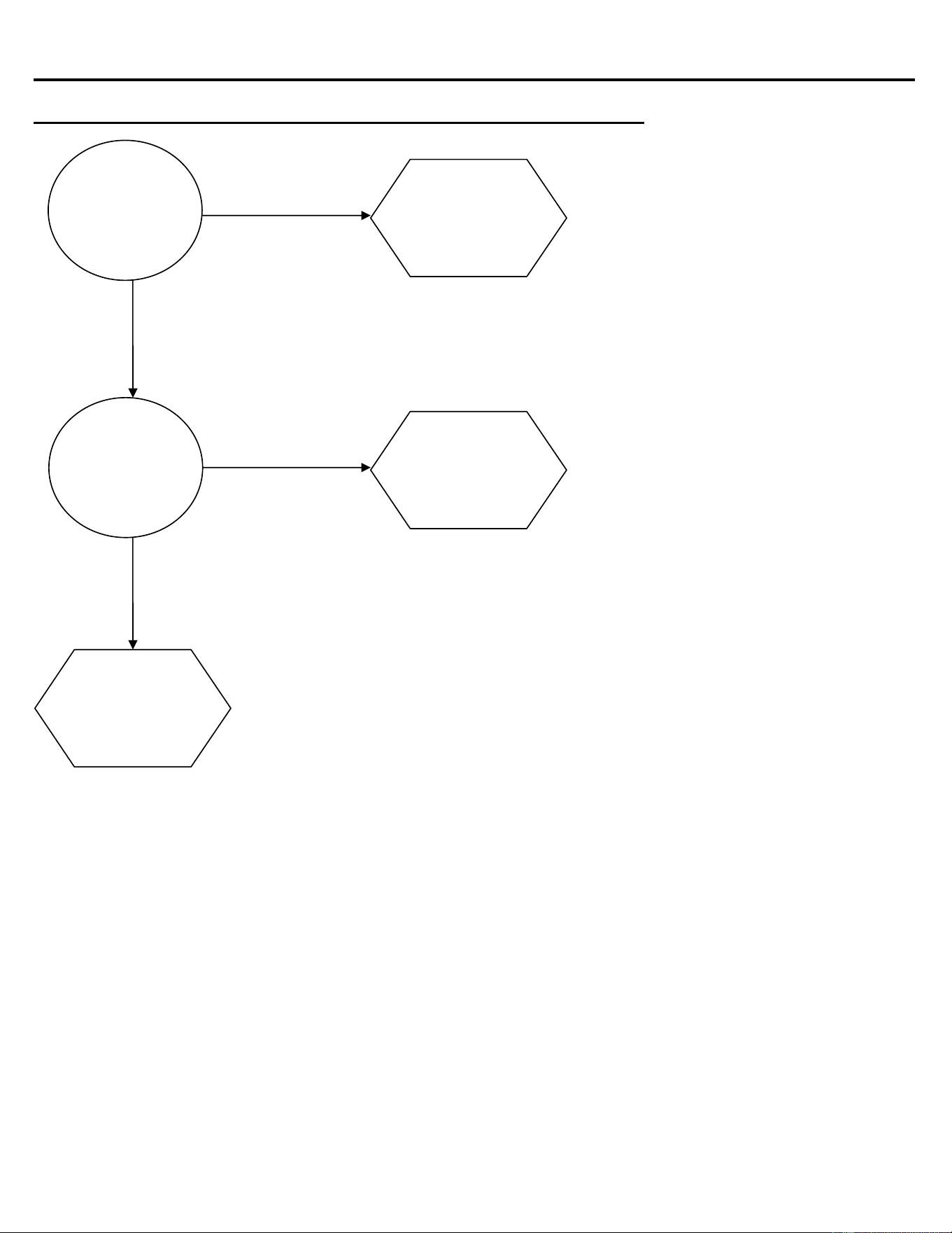
Machine Produces Cloudy Ice
Is water
running evenly
across the
evaporator?
NO
YES
See “Poor
Water Running
Over Evaporator
Troubleshooting
Tree page C13
NO
YES
Doe machine
meet
installation
guidelines?
See Section A
Cloudiness is a
result of properties
in the incoming
supply water
Correct
installation
deficiency
ICE Series Troubleshooting Trees
Page C13
Poor Water Distribution Over The Evaporator
YES
Is the machine
level?
Check Water
Distribution Tube for
obstructions or
improper assembly
See Section D
NO
YES
YES
Correct
deficiency in
supply water
pressure
Level the
machine
Is the supply
water
pressure
correct?
NO
BAD
Is the water
level in the
Water Trough
correct? See
Section D
Purge valve
stuck open,
clean or replace
if defective
Float Valve not
adjusted
properly or
could be
defective
YES
Check Water Pump
for proper operation
Water Pump
obstructed or
may be
defective
Clean Water
Distribution
Tube; insure
that it is
assembled
correctly
NO
OBSTRUCTED CLEAR
GOOD
Clean
Evaporator and
Spillway. See
Section B for
cleaning
instructions
Is water
leaking from
the Purge
Drain?
NO
ICE Series Troubleshooting Trees
Page C14
Machine Does Not Enter Harvest
YES
Will suction
pressure drop
below cut-in of
Timer Initiate?
Check Purge Valve
to make sure it is not
leaking, if it is
replace valve or
remove obstruction
OK
Hot Gas Valve
could be leaking
Does the
manual Purge
Switch
energize the
Purge Valve?
NO
O
K
Is the freeze
pattern on the
Evaporator
even?
TXV(s) may be
stuck open, see
page E3 and E4
Timer Initiate
Control out of
adjustment or
may be
defective
YES
Check for signs of a
weak Compressor,
see page E1
High
Temperature
Safety Control
may be open,
see page F8
Check Timer
Number 2
NO
NOT OK
Make sure system is
not overcharged
Check Timer Initiate
Control for correct
cut-in pressure
Check Timer
Number 1 for proper
setting and
operation
NOT OK
O
K
O
K
YES
O
K
Relay Number 1
or Relay Base
may be
defective
O
K
Timer may be
defective
NO
ICE Series Troubleshooting Trees
Page C15
Machine Enters Harvest, Then Returns To Freeze Prematurely
YES
Is the Harvest
Assist working
properly? See
page F6
Check the Manual
Purge Switch
Normally Closed
contacts. See page
F1
Purge Switch is
defective
OPEN
Adjust as
required or
replace
defective part
Check High
Temperature Safety
Control. See page
F8
OPEN
CLOSED
CLOSED
Relay 1 or relay
Base may be
defective
NO
High
Temperature
Safety Control is
defective
ICE Series Troubleshooting Trees
Page C16
Length Of Harvest Excessive
YES
Does the
machine meet
installation
guidelines?
Correct
installation
deficiency
NO
Check Harvest
Assist Assembly for
proper operation,
see page F6
Low refrigerant
charge, repair
leak and weigh
in proper charge
Is the ice
formation
even on the
Evaporator?
Adjust or
replace
defective part
Hot Gas Valve
may be
defective
Remote: Check
Mixing Valve
operation, page E6
Water Cooled: check
Water Valve for
proper adjustment
NOT OK
Does the
machine have
a remote
condenser?
Check suction
pressure during
harvest. See page
E5
Clean Evaporator
per instructions in
Section B
OK NO
YES
YES
NO
OK
OK
TOO LOW
STILL TOO LONG
Go to “Ice Does
Not Release”
Troubleshooting
Tree, page C17
ICE Series Troubleshooting Trees
Page C17
Ice Does Not Release From Evaporator
YES
Clean the
Evaporator, see
page B2
NO
OK
YES
Level the
machine
Set proper
bridge
thickness, see
page F4
Does water
run over the
Evaporator
during
harvest?
OK
TOO LOW
Is the machine
level?
Replace Purge
Valve or repair
tubing
obstruction
Hot Gas valve
may be
restricted or
defective, see
page E5
OK
Check Harvest
Assist for proper
operation, see page
F6
NO
Selector
Switch may be
defective,
WASH contacts
closed in ICE
mode
Relay or Relay
Base defective
NO
GOOD
NOT OK
Check Purge valve
and Tubing for
obstructions and
proper operation,
see page D2
Check Relay 1 and
Relay Base for
proper operation,
see page F5
Check suction
pressure during
harvest, see page
E5
Check discharge
pressure during
freeze, see page E2
Repair Harvest
Assist as
required
OK
GOOD
NOT OK
TOO LOW
YES
Evaporator may
be defective,
see page E4
and E5
Is the ice
bridge
correct? See
page F4
Low ambient or
Water regulating
Valve set too
low
ICE Series Troubleshooting Trees
Page C18
Hot Evaporator, Low Suction And Discharge Pressure (Remote Only)
YES
Correct
installation
deficiency
Does the
machine have
the proper
refrigeration
charge?
NO
NO
YES
Does the
machine meet
the installation
guidelines?
Repair leak,
evacuate and
weigh in
refrigerant
charge per
nameplate
Mixing Valve
may be
defective, see
page E6
ICE Series Water System
Page D1
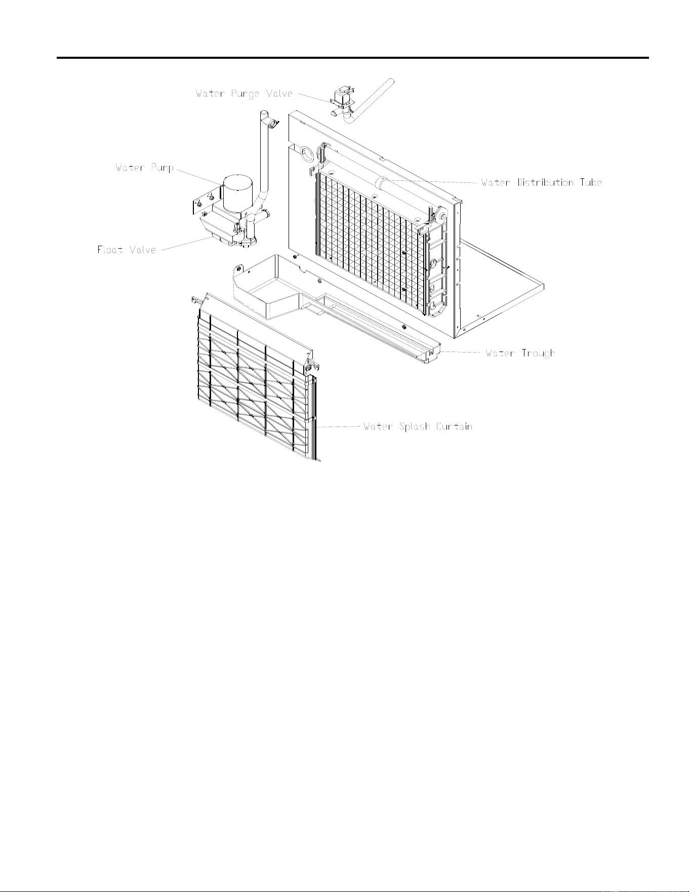
Water Distribution and Components
Water enters the machine through the float valve located in the water trough. The water trough
holds water used for ice making. The float valve is used to maintain the proper water level in the
water trough. During the freeze cycle water is continuously circulated over the evaporator by the
water pump. When the machine enters harvest, the purge valve (not shown) opens and mineral
laden water is pumped out of the water trough to the drain. After water is purged from the trough,
the water pump and purge valve are de-energized and the trough refills.
Note: The operation of the Hot Gas Valve and Water Pump vary by model number, reference
the wiring diagram on the specific model number for operation sequence.
Float Valve
The water level can be adjusted by carefully bending the arm of the float. The water level should
be ½ inch (13mm) above the top of the water pump impeller housing during the freeze cycle.
If the float valve does not allow water into the trough or water flow is slow, the float valve may be
restricted. Remove and disassemble the float valve and clean the orifice. If the water flow is still
slow, check the water pressure to be sure it is at least 20 PSI (1.4 bar).
If the float valve does not stop the water flow, make sure the water pressure to the machine does
not exceed 60 PSI (4.1 Bar). Install a water pressure regulator if the pressure is too high. If the
water pressure is not the problem, the float plunger or the entire float valve assembly may need to
be cleaned or replaced.
ICE Series Water System
Page D2
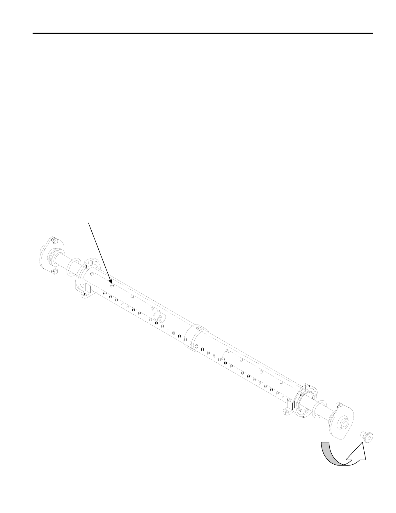
Water Distribution Tube
Water is pumped to a distribution tube located at the top of the evaporator and is used to distribute
water evenly over the evaporator. The distribution tube can be removed and dissembled for
cleaning if the hole becomes plugged or if there is excessive mineral build-up in the water system.
The water distribution tube is a tube within a tube. Water enters and fills the inner tube and exits
through a series of holes along the top of the inner tube. Water then fills the outer tube and exits
through a series of holes along the bottom of the outer tube. For proper water flow over the
evaporator, it is important that the tube be assembled correctly after cleaning. The tube can be
checked for proper assembly by checking the “bump” on the flanges at the tube ends, the “bump”
should be at the top.
Water Distribution Disassembly
Remove 2 screws holding the distribution tube to the evaporator spillway. Remove the clamp
holding the water tube to the distribution tube. Twist the end caps of the distribution tube
counterclockwise and pull to remove the inner tube halves from the outer tube. To reassemble,
push the inner tube halves into the outer tube with the holes facing the same direction. Make sure
the inner tube halves seat together completely. Twist the end caps clockwise ½ turn to lock the
inner tubes in place. The holes in the tubes will now be facing in the opposite directions. e directions.
Important! For proper water flow over the evaporator, the inner tube holes must face up. Important! For proper water flow over the evaporator, the inner tube holes must face up.
Turn counterclockwise to remove
ICE Series Water System
Page D3
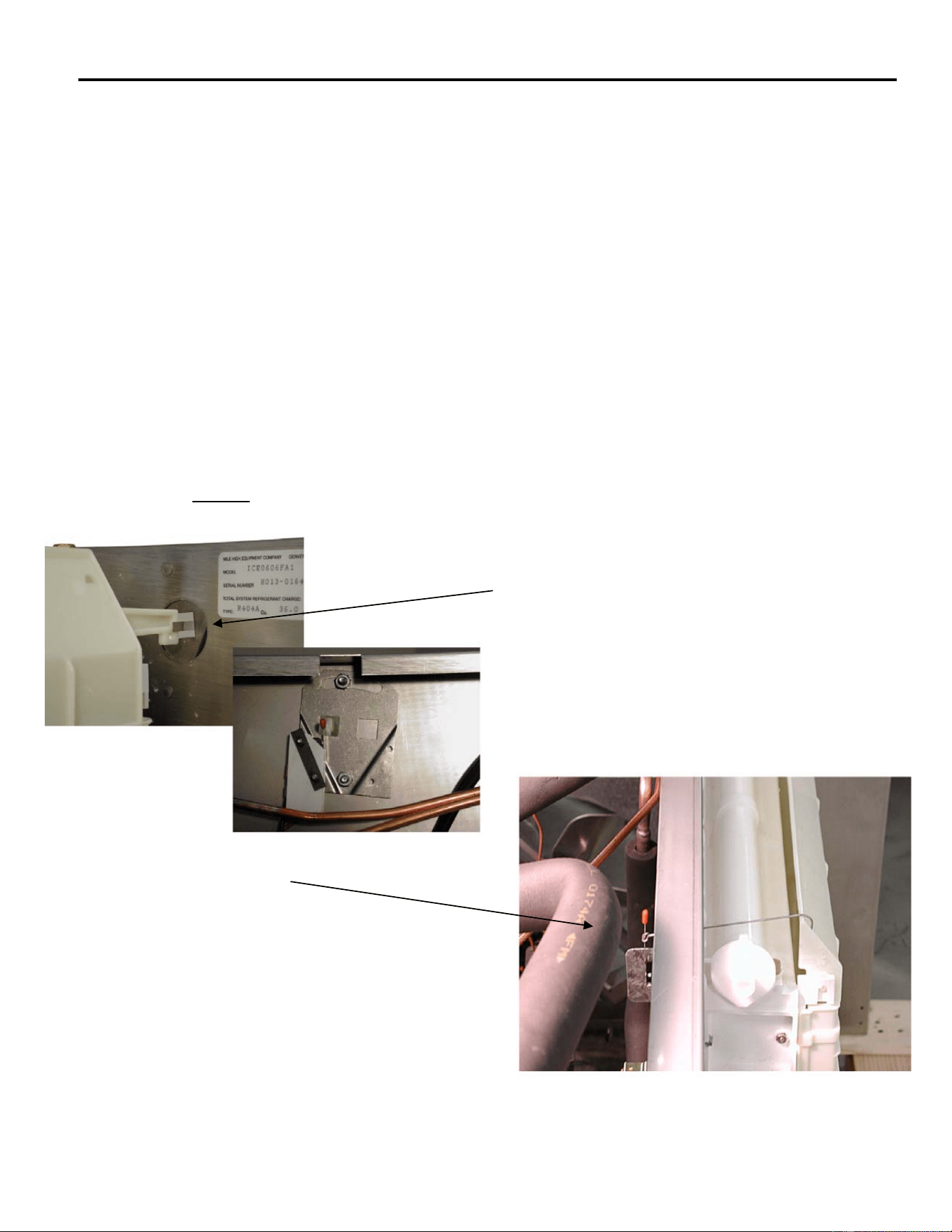
Water Splash Curtain
The water splash curtain covers the evaporator to prevent water from splashing into the bin and is
also used to actuate the bin switch. When the bin becomes full of ice, the splash curtain is held
open when the ice drops off of the evaporator. The actuator tab or wire bale on the splash curtain
will release pressure on the bin switch and the machine shuts off. See bin control on page F9.
On single evaporator units, and the ICE1506R3 and 1506R4, the splash curtain can be opened or
removed during the freeze cycle and the machine will continue to run until the ice drops from the
evaporator. On dual evaporator units, if the curtain is opened or removed during the untimed
freeze cycle, or during defrost, the machine will shut down. If the curtain is opened or removed
during the timed freeze cycle, the unit will continue to operate.
The splash curtain can be removed by swinging the bottom of the curtain away from the
evaporator and lifting the right side of the curtain up and out of the hinge pin slot. To reinstall the
curtain, position the left side pin into the slot first, then insert the right hand side with the actuator
tab of the curtain behind the bin switch.
Note: The ICE0250 and ICE0305 utilize a curtain-retaining clip. The ICE Undercounter Series
ice machines do not utilize a splash curtain.
Water splash curtain actuator tab
positioned behind bin switch
Proper position of wire bale switch actuator
(Early 48 inch units)
ICE Series Water System
Page D4
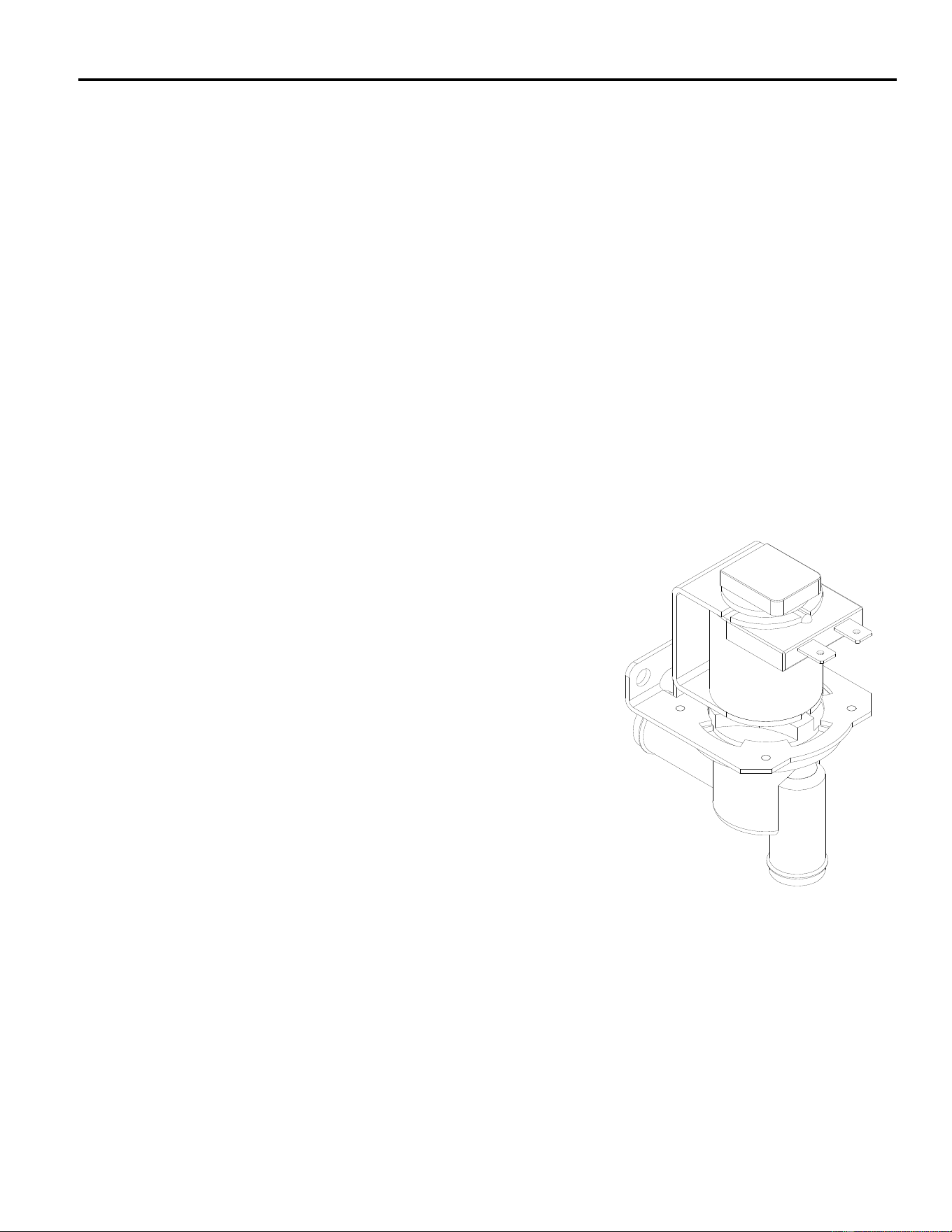
Water Purge Valve
When the machine enters the harvest cycle, the water pump continues to run and the purge valve
opens. This allows mineral laden water to be pumped from the water trough to the drain. This
helps keep the water system clean. The water pump and purge valve de-energizes once the water
is flushed from the water trough. The cam switch controls the length of time that the water pump
and purge valve remains energized see page F7. The purge valve can also be energized
manually by pushing the purge switch. The purge switch is used when cleaning the water system
to flush cleaning solution down the drain. See page B1 for cleaning instructions.
The purge valve must be completely closed during the freeze cycle. If water leaks through the
purge valve during the freeze cycle, the freeze cycle will be extended due to the float allowing
warm water into the trough and poor ice formation will result. The purge valve may be defective or
need cleaning.
The purge valve can be disassembled for cleaning by:
1. Disconnect electrical power from the ice machine.
2. Locate the Purge valve in the machine.
3. Leave the coil wires attached to the coil and lift coil from the valve body. (Note coil orientation)
4. Rotate the enclosing tube ¼ turn counterclockwise to remove.
5. Remove the enclosing tube, plunger and diaphragm from the valve body
6. Reverse procedure to reassemble.
The purge valve can be easily cleaned without removing the
entire valve body. Dirty or clogged purge valves are not
considered a warranty repair.
ICE Series Water System
Page D5
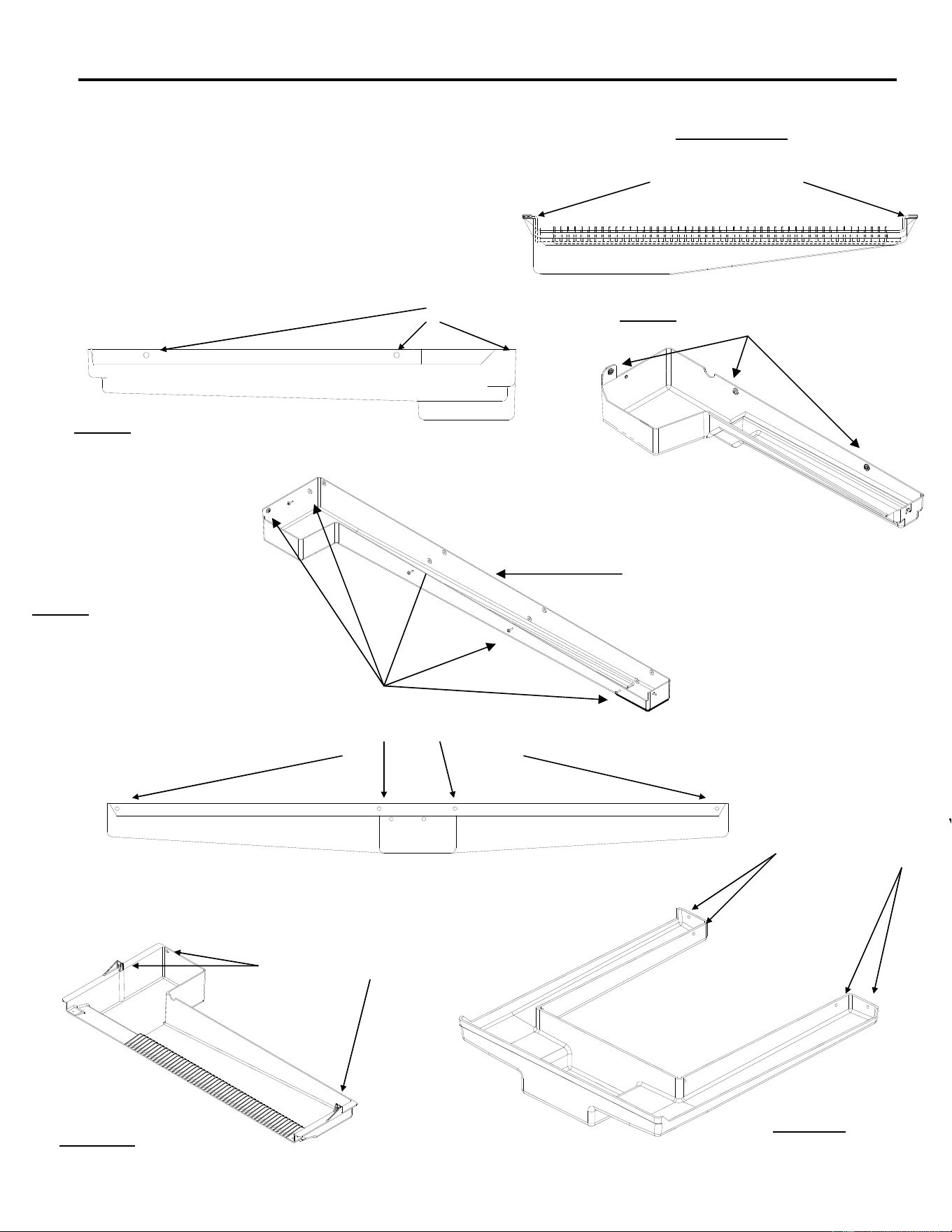
Water Trough
The water trough can be easily removed by the following procedures:
Mounting Screws
ICEU150/200 Models
1. Disconnect power to the ice machine.
2. Shut the water supply off to the ice machine.
3. Remove water splash curtains when
applicable.
4. Remove water trough mounting screws.
5. Carefully remove water trough from the ice
machine.
6. Reverse procedure to reassemble.
ICE 22 Inch Wide Models
Mounting Screws
ICE 30 Inch Wide Models
ICE 48 Inch Wide Models
Mounting Screws
Mounting Screws
Mounting Screws
Mounting Screws
Version 3 Water
Trough
ICE1506 Model
ICEU300
ICE Series Refrigeration System
Page E1
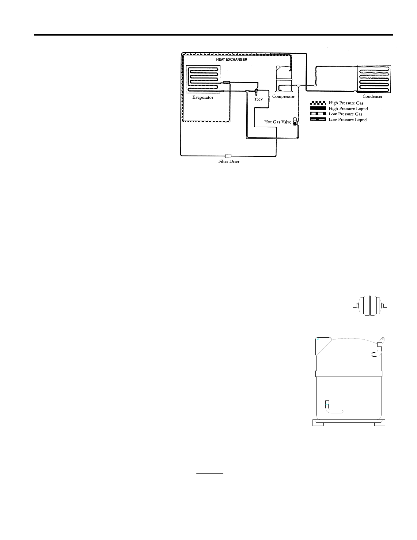
Refrigerant Cycle and
Components
Before diagnosing the refrigeration
system, it is very important that the
refrigerant charge be correct.
Whenever the refrigeration system
has been opened, the filter-drier
must be replaced and the proper
refrigerant charge must be weighed
in. See refrigerant charge data on
pages H1.
Refrigerant Pressures
The suction pressure at the
beginning of the freeze cycle can vary +/- 10 psi
(.7 bar) depending on operating conditions. Reference Chart on pages I1. Pressures less than
this may indicate an undercharge. The discharge pressure on water-cooled units should be 250
psi (17.01 bar) for R404a units and 150 psi (10.21 bar) for R134a units. The discharge pressure
on air cooled units will vary with ambient conditions but will typically run higher than water cooled
units. Remote condensers located in ambient temperatures below 70°F (21°C) will typically run a
lower discharge pressure. See Mixing Valve later in this section.
Refrigerant in a gas state is pumped throughout the refrigeration system by a hermetic
compressor to the condenser. Heat is removed from the refrigerant either by forced air
movement through an air-cooled condenser or transferring heat from the refrigerant to water
through a water-cooled condenser. The refrigerant changes to a liquid when cooled.
The refrigerant in a liquid state passes through a filter drier. The filter drier traps
small amounts of moisture and foreign particles from the system. The filter drier must
be replaced whenever the refrigeration system is opened or if the refrigerant charge
has been completely lost.
Compressor
The compressor runs during the entire cycle. If the valves in the
compressor are damaged, the compressor will be unable to pump
refrigerant efficiently. Damaged valves are usually the result of another
problem in the refrigeration system such as liquid refrigerant returning to
the compressor, oil slugging or high head pressure. When a compressor
is replaced it is important that the refrigerant charge be weighed in and
the system checked for proper operation to prevent a repeat failure.
An inefficient compressor will usually have a higher than normal suction
pressure at the end of the cycle. The freeze cycle will be longer than normal and/or the harvest
cycle may be excessively long. Check the compressor amperage draw 5 minutes into the freeze
cycle. If the compressor amp draw (Reference data plate on ice machine back panel) is less than
70% of rated full load amps, the compressor may be inefficient. These symptoms may also be
caused by other problems, therefore it is important to use the troubleshooting trees when
diagnosing a problem. See Electrical System for more information on the compressor and
compressor start components.
ICE Series Refrigeration System
Page E2
Air Cooled Condenser (Self Contained)
The air condenser is located in the back of the cabinet. Air is pulled
through the condenser by a fan motor and discharged through the right
hand side panel. The ICE1400 has 2 fan motors and discharges through
the right side and left side panels. The ICE Undercounter air intake
and discharge is through the front panel. A top air discharge is available
on the ICE250-ICE0606. The Fan Control closes at 250 psi and opens
at 200 psi.
Do not block airflow as it will cause premature failure of the machine and will void the
warranty.
Water Cooled Condenser
If the machine has been properly installed, the water flow through the
condenser will be in a direction opposite the refrigerant flow. The water
condenser supply pressure must be between 20 psi (1.4 bar) and 60 psi
(4.1 bar). A water-regulating valve is used to control the flow of water
into the condenser. In areas that have poor water quality, the
condenser may eventually become coated with mineral deposits. This
will decrease the efficiency of the condenser resulting in high head
pressure. Water cooled condensers replaced due to excessive mineral
build up or freezing will not be covered under warranty.
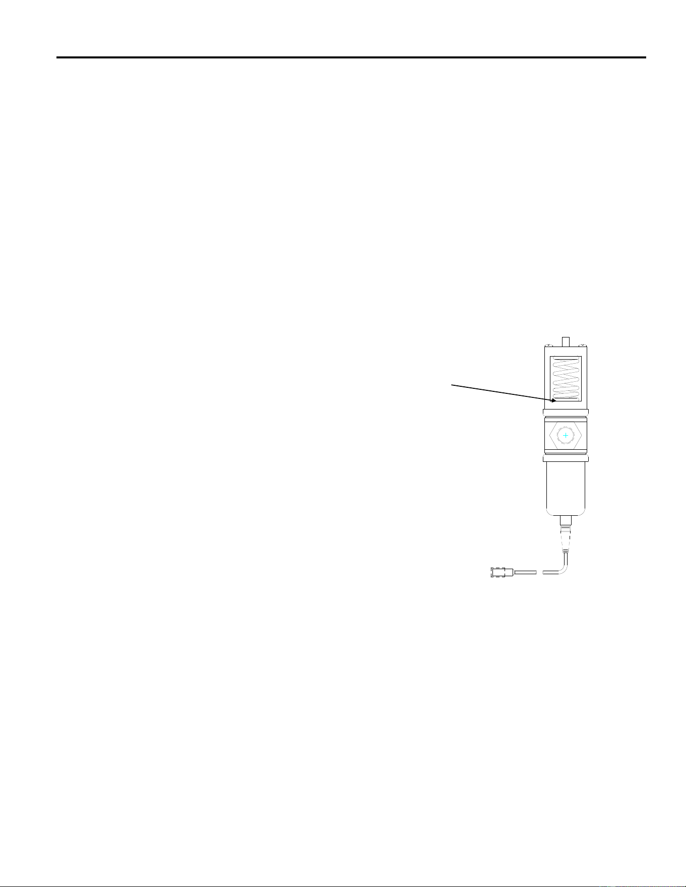
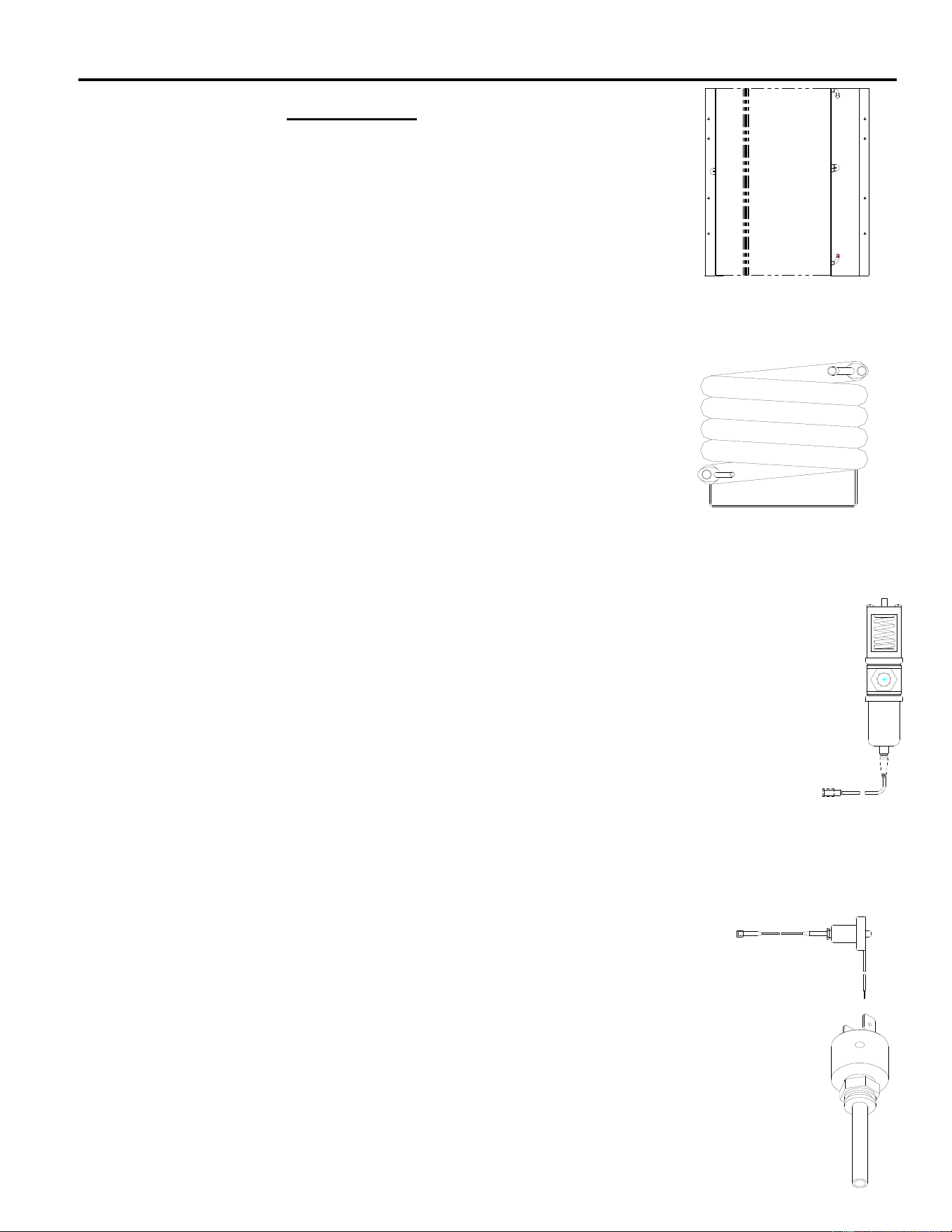
Water Regulating Valve
The water-regulating valve controls the head pressure by regulating the amount of
water flow through the condenser. The bellows of the regulating valve are
connected to the high-pressure side of the refrigeration system. As the head
pressure rises, the bellows expand increasing the water flow through the water
condenser. Adjusting the spring pressure screw on top of the water valve can vary
the rate of water flow. The valve should be adjusted to maintain a discharge
pressure of 250 psi (17.01 bar) on R404a units and 150 psi (10.21 bar) on R134a
units. Water exiting the condenser should be between 100°F (38°C) and 110°F
(43°C). When the machine is off, the water valve will close completely, stopping the
flow of water through the condenser. If the water flow does not stop when the
machine is off, the valve may need cleaning or replaced.
Air Cooled Condenser (Remote) See Pages E5 and E7
High Pressure Safety Control (Manual Reset)
If the discharge pressure becomes excessive, the high-pressure safety
control will open and shut the machine off. The high-pressure safety control
opens at 450 psi (30.62 bar) on R404a units and 250 psi (17.01 bar) on
R134a units. The high-pressure safety control is used on all water-cooled
and remote units and select air-cooled units.
High Pressure Safety Control (Automatic Reset)
The automatic reset high pressure control opens at 450 psi (30.62 bars) and closes at
338 psi (23.00 bars). The high-pressure safety control is used on all water-cooled and
remote units and select air-cooled units.

ICE Series Refrigeration System
Page E3
Thermostatic Expansion Valve (TXV)
The thermostatic expansion valve meters the flow of refrigerant into the
evaporator changing its state from a high-pressure liquid to a low-pressure
liquid. This drop in pressure causes the refrigerant to cool. The cooled
refrigerant absorbs heat from the water circulating over the evaporator. As
the evaporator fills with liquid refrigerant, the evaporator becomes colder.
The flow of refrigerant into the evaporator is controlled by the temperature at the outlet of the
evaporator. The expansion valve bulb, mounted to the top of the suction line, senses the
evaporator outlet temperature causing the expansion valve to open or close. As ice forms on the
evaporator, the temperature drops and the flow of refrigerant into the evaporator decreases,
resulting in a drop in suction pressure.
The evaporator should become completely flooded (filled with liquid refrigerant) during the freeze
cycle. A completely flooded evaporator will have a uniform freeze pattern (ice formation across the
evaporator). A starved evaporator (not enough liquid refrigerant) will have poor or no ice formation
at the top of the evaporator, and the tube(s) exiting the evaporator will not frost. All tubes should
be within 10 degrees of each other and frosted approximately 5 minutes from the start of the freeze
cycle.
An expansion valve that is restricted or not opening properly will starve the evaporator resulting in
lower than normal suction pressure. A low refrigerant charge will also starve the evaporator and
cause low suction and discharge pressures. If not sure of the amount of charge in the system, the
refrigerant should be recovered and the correct charge be weighed in before a defective valve can
be diagnosed.
If the evaporator is starved but the suction pressure is higher than normal, the TXV is not the
problem; refer to the troubleshooting tree in section C. If the TXV sticks open or if the thermal bulb
is not making good contact with the suction line, the flow of refrigerant into the evaporator will be
too great and liquid refrigerant will flood the compressor. The suction pressure will remain higher
than normal and the machine will remain in an extended freeze cycle. Ice will build evenly but will
be very thick.
Symptom Problem Possible Remedy
Evaporator flooded but suction 1 TXV thermal bulb not making 1 Tighten bulb clamp and
pressure not dropping. good contact with suction insulate bulb.
Compressor has been checked line or uninsulated
and appears to be good. 2 TXV bulb installed incorrect 2 Locate bulb on top of
Suction line at compressor may suction line
be colder than normal 3 System overcharged 3 Recharge system
4 TXV stuck open 4 Replace TXV
Evaporator starved, no frost 1 Machine low on charge 1 Recover refrigerant
on line(s) exiting evaporator. and weigh in proper
Suction pressure is low. charge
See Evap. Diagram Pg.E4 2 TXV restricted or stuck 2 Replace TXV and
closed drier
Continued Page E4
ICE Series Refrigeration System
Page E4
Thermostatic Expansion Valve (Continued)
A dual evaporator machine will have one TXV for each evaporator. If one TXV sticks open and the
other is operating normally, the suction pressure will be higher than normal and both evaporators
will build thick ice. It is recommended that both valves be replace if one sticks open.
If one TXV sticks closed and one is operating normally, the suction pressure will be normal or low
but the evaporator with the defective valve will be starved (thick ice at the bottom and thin ice at
the top).
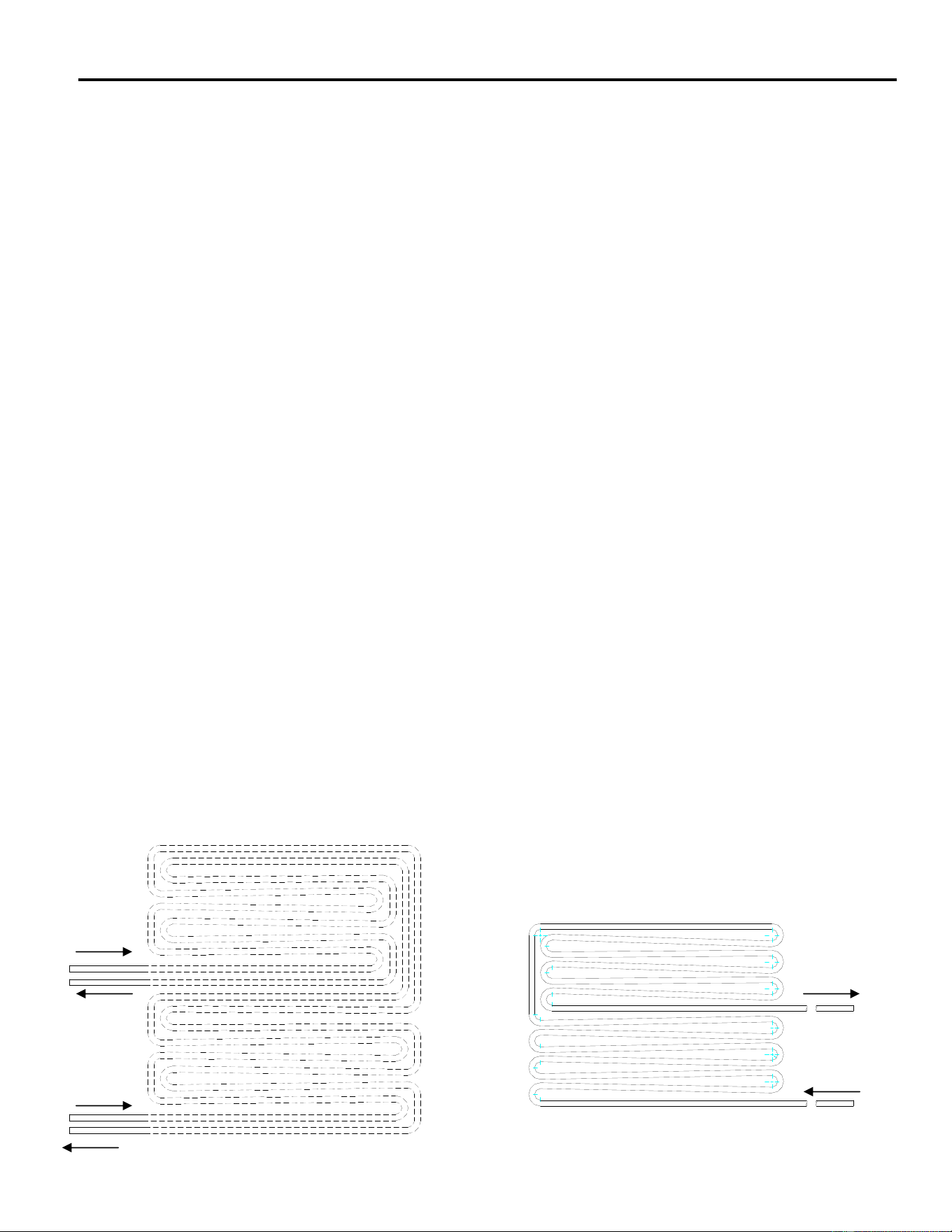
Evaporator
As water is circulated over the front of the evaporator, liquid refrigerant is circulated through the
tubing attached to the back of the evaporator. As the liquid refrigerant in the tubing vaporizes, it
absorbs heat from the water causing the water to freeze. The evaporator should be completely
flooded throughout most of the freeze cycle. A flooded evaporator will build ice evenly across the
evaporator. A starved evaporator will have uneven ice formation. Most problems with ice
formation or harvesting are not related to a defective evaporator, use the Troubleshooting Trees in
section C for additional help.
Refrigerant enters the evaporator through the bottom tube and exits through the top tube. On
(Prior to 0801) models ICE800, 1000, 1800 and 2100 the refrigerant line at the TXV outlet splits
into two feeder tubes. This split occurs at the distributor, which is a fitting that is soldered to the
TXV. One feeder tube from the distributor feeds the top of the evaporator; the other tube feeds the
bottom of the evaporator. The evaporator tubes run parallel, in opposite directions, along the back
of the evaporator creating a dual pass.
If the evaporator is flooded but not building ice evenly, it is possible the evaporator has coil
separation. Evaporator coil separation is the separation of the refrigerant tubing from the back of
the evaporator plate. This is very rare but occasionally occurs.
To confirm coil separation, remove and check the back of the evaporator. If the coil is separated,
the evaporator must be replaced. If the outlet(s) of the evaporator is not frosted, the problem is not
with coil separation (Refer to the troubleshooting trees, section C).
Out
In
In
Out
In
Out
ICE800, 1000, 1800 and 2100 Prior to Jan, 2008
ICE0855G, ICE0856G, ICE1006A6, ICE1006W5, ICE1006R6
ICE Series Refrigeration System
Page E5
Note: Permanent discoloration of the evaporator plating is normal and will cause no problems with
harvesting the ice or sanitary conditions. Before condemning the evaporator for plating problems,
be certain it is not just discoloration. Good evaporators will not be covered under warranty. If the
spillway (plastic evaporator top) becomes damaged, it can be replaced. It is not necessary to
replace the entire evaporator.
As liquid refrigerant leaves the evaporator, it changes to a low-pressure gas before returning to the
compressor. Liquid refrigerant must not return to the compressor or damage will result. Frost on
the suction line at the inlet of the compressor indicates liquid returning to the compressor. Check
for frost at the end of the freeze cycle. If liquid is returning to the compressor, the problem must be
located and corrected. See Refrigerant Charge, Thermostatic Valve and Evaporator.
Harvest Cycle
Once the freeze cycle is complete, the machine enters the harvest cycle. The hot gas valve
opens to allow hot discharge gas to enter the evaporator.
Hot Gas Valve
When the machine enters harvest the hot gas valve coil is energized opening
the hot gas valve. Discharge gas is pumped through the hot gas valve directly
into the evaporator. The evaporator temperature will reach approximately 40°F
(4.5°C). The suction pressure during harvest should be a minimum of 70 psi
(4.8 bar) for R404a units or 50psi (3.4 bar) for R134a units. The discharge
pressure will drop during harvest.
If the hot gas valve does not completely open during harvest, there will not be enough hot gas in
the evaporator to defrost the ice. If there is not enough hot gas entering the evaporator, the
suction pressure will be lower than the above stated pressures. It is important when making this
check that the machine has the proper refrigerant charge, normal head pressure and the
compressor is functioning properly. If the hot gas valve leaks during the freeze cycle, ice will not
form on the top of the evaporator and suction pressure will be higher than normal. To check if the
hot gas valve is leaking, let the machine run in the freeze cycle for approximately 5 minutes. Now
feel the temperature between the inlet and outlet of the valve. A definite temperature difference
should be felt. If the lines are the same temperature and the suction pressure is higher than
normal; the valve is leaking and should be replaced. Use Troubleshooting Trees in section C.
Remote System
Machines that use remote condensers have several components that are not used in self
contained machines. A mixing valve controls the head pressure when the ambient temperature at
the condenser drops below 70°F (21°C). When the bin fills with ice or is turned off at the selector
switch, the machine will pump all the refrigerant into the receiver before shutting off.
Remote Condenser
For proper operation, the remote condenser must be installed properly.
Improper installation will void the warranty. See remote guidelines on page
A17. The location of the remote condenser should be such that the ambient
air temperature does not exceed 120°F (48.9°C). If ambient temperature
exceeds 120°F (48.9°C) ice production will decrease until the ambient
temperature decreases.
Air
Flow
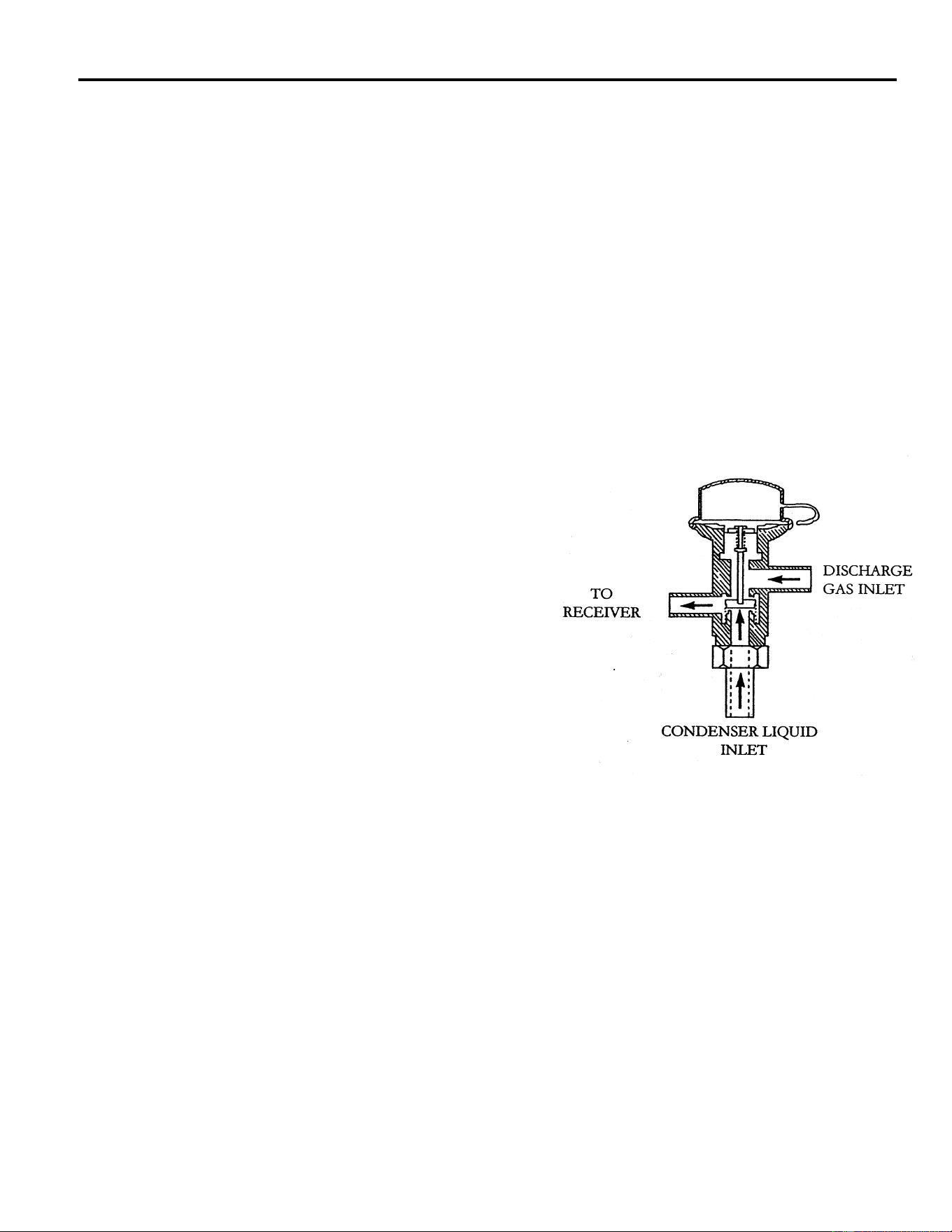
ICE Series Refrigeration System
Page E6
Remote Condenser (Continued)
If the airflow is restricted or the condenser is dirty, the head pressure will be excessively high, slow
production will result and the compressor may overheat and eventually become damaged. The
condenser coil and fan blades must be kept clean. The condenser can be cleaned with
compressed air or by using a brush. If a brush is used, brush in the direction of the fins taking care
not to bend the fins. If the condenser fins are bent, this will restrict the airflow through the
condenser and the fins will need to be straightened with a fin comb. Problems related to a dirty
condenser or poor airflow will not be covered under warranty. Note: The condenser fan motor runs
continually, it will shut off when the icemaker shuts off.
Mixing Valve
When the temperature at the condenser is above 70°F (21°C), the refrigerant flow from the
compressor is directed by the mixing valve through the condenser and into the receiver. When the
temperature at the condenser drops below 70°F (21°C), the pressure in the bellows of the mixing
valve becomes greater than the pressure of the liquid refrigerant coming from the condenser. This
change allows the valve to partially restrict the flow of
refrigerant leaving the condenser and allows discharge
gas to by-pass the condenser and flow directly into the
receiver, mixing with the liquid refrigerant from the
condenser. The amount of discharge gas that
bypasses the condenser increases as the ambient
temperature decreases. This action of the mixing
valve allows the discharge pressure to be maintained
at approximately 240 psi* (16.5 bar) during low
ambient conditions. If the refrigerant system is
undercharged and the ambient temperature is below
70°F (21°C), the mixing valve will not work properly.
The mixing valve will allow too much refrigerant to
bypass the condenser.
*Note: Mixing Valve pressure varies by Ice Machine
model number.
Problem Possible Cause Remedy
1 Head pressure low, Line between A. Valve Defective, not allowing A. Replace valve
valve and receiver cold. Ambient discharge gas into receiver
condenser temp. below 70°F (21°C)
2 Head pressure low, Line between A. System low on charge. A. Leak check. Recover
valve and receiver hot. B. Valve defective, not refrigerant and weigh
allowing liquid in proper charge.
into receiver. B. Replace valve
3. Head pressure low, Line A. Valve defective not A. Replace valve.
returning from condenser allowing refrigerant
is cool. Ambient condenser to circulate through
temperature is above 70°F (21°C) condenser.
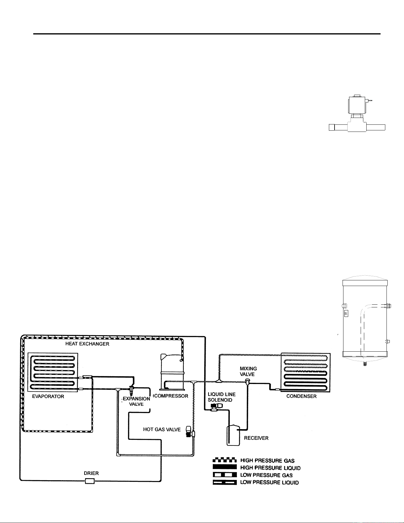
ICE Series Refrigeration System
Page E7
Pump Down System (Remote Only)
The pump down system prevents liquid refrigerant from migrating to the evaporator and
compressor during the off cycle and prevents the compressor from slugging or starting under an
excessive load.
Liquid Line Solenoid
When a machine with a remote condenser shuts off, the liquid line solenoid valve,
located at the outlet of the receiver, is de-energized causing the valve to close
completely restricting the flow of refrigerant. The compressor will pump all of the
refrigerant into the condenser and receiver.
As the system pumps down, the pressure on the low side of the system drops. When the suction
pressure drops to 10 psi (Sea Level, .68 bar), 12.5 psi (5,000 Feet .82 bar) the pump down
control opens and shuts the machine off. See page F9 for pump down control operation. Liquid
refrigerant is stored in the condenser and receiver while the machine is off. It is normal for the
machine to pump down once or twice an hour as the pressures equalize.
When the machine comes back on (the bin switch closes or the selector switch placed to the ICE
position), the liquid line solenoid valve opens and the refrigerant is released from the receiver.
When the suction pressure rises to 35 psi (Sea Level, 2.38 bar) 37.5 (5,000 Feet 2.59 bar) the
pump down control closes and the machine comes back on. If the machine will not pump down,
the valve may not be closing all the way. A weak compressor will also prevent the machine from
pumping down. Check for signs of a weak compressor before replacing the liquid line solenoid.
Prior to replacing the valve, disassemble and check for obstructions that may not allow the valve to
seat.
Receiver
If the system has a remote condenser, the refrigerant will enter a receiver before
passing through the filter drier. The receiver holds reserve liquid refrigerant during
the freeze cycle. The receiver also stores liquid refrigerant during the off cycle.

ICE Series Refrigeration System
Page E8
Refrigerant
Refrigerant in a high-pressure liquid form is fed to an expansion valve where the refrigerant is
reduced to a low-pressure liquid. Under this low pressure, the liquid will absorb heat from the
evaporator causing the liquid to change to a vapor. This vapor is the drawn into the compressor
where the temperature and pressure of the vapor are increased. The high temperature, high
pressure vapor flows to the condenser where the heat is removed, causing the vapor to return to
the liquid form, making the refrigerant ready to flow back to the evaporator to pick up more heat.
Most Ice-O-Matic ice machine use R134a or R404a refrigerant. Always check the serial number
data plate for the proper type of refrigerant and the amount used in the machine you are servicing.
R404a and R134a are both HFC refrigerants, which result in no ozone depletion factor. R404a
cylinders are orange in color, R134a cylinders are light blue in color.
Important: When discharging refrigerant from an icemaker, recover as much of the
refrigerant as possible with a recovery device or some other means to prevent the
refrigerant from entering the atmosphere.
Method of Charging Refrigerant
In order to achieve a properly charged refrigeration system, the system must be completely
evacuated.
To achieve a complete evacuation you will need a service gauge manifold with properly maintained
hoses, and a vacuum pump capable of pulling a 50-micron vacuum. This will require a two-stage
pump.
Connect the service gauge manifold to the high and low side service ports and vacuum pump.
Make sure the valves on the gauge manifold are closed, then start the pump.
Note: Do not use a refrigeration compressor as a vacuum pump. Compressors are able to
pull only a 50,000-micron vacuum.
After the vacuum pump has been started, open the valves on the gauge manifold. This will allow
the refrigeration system to start being evacuated.
If there has not been an excessive amount of moisture in the system, allow the vacuum pump to
pull the system down to about 200 microns or 29.9 inches or less. Once this has been achieved,
allow the vacuum pump to operate for another 30 minutes. Then close the valves on the gauge
manifold and stop the vacuum pump. Then watch your gauges. A rise to 500 microns in three (3)
minutes or less indicates a dry system under a good vacuum.
If your gauge registers a more rapid rise, the system either has moisture remaining or there is a
leak in the system, requiring a check for the leak, and repair and another complete evacuation.
Note: Seal the ends of the gauge manifold hose and pull them into a deep vacuum to determine if
the leak is not in the hoses. The gauge manifold should be able to hold the vacuum for three (3)
minutes.

ICE Series Refrigeration System
Page E9
If the refrigeration system is extremely wet, use radiant heat to raise the temperature of the
system. This action will cause the moisture to vaporize at less of a vacuum.
The use of two (2) valves, one between the vacuum pump and gauge manifold and the other
between the refrigerant cylinder and the gauge manifold allows you to evacuate and charge the
system without disconnecting any hoses. If the hoses were disconnected, air or moisture will have
the opportunity to enter the hoses and then the system.
A properly charged icemaker is a service technician’s greatest ally. Proper charging will allow any
concern with the icemaker to be accurately diagnosed.
The refrigerant charge must be weighed into the icemaker either by using a charging scale or with
a dial-a-charge.
The amount of proper refrigerant required for the icemaker is printed on the serial data plate
attached to the icemaker and is listed on the following pages. Never vary the amounts from those
listed.
Important!
Pre VRC Models
Remote models with sixty (60) foot lineset runs will need an additional fifteen (15) ounces of
refrigerant added.
VRC Models
Maximum actual line set run is limited to 100 ft. Add ¼ ounce of refrigerant for each actual foot
from 75 feet to 100 feet actual lineset run.
In some cases the complete refrigerant charge may not enter the refrigeration system. In those
instances, close the gauge manifold high side valve and disconnect the manifold from the high side
port.
When the icemaker is completely charged, secure the caps to the service ports and check to make
sure the ports are not leaking refrigerant.
Reference Tables on Page I6 and I16.

ICE Series Electrical System
Page F1
Control Circuit
All machines in this manual are electro-mechanical controlled; however the control circuitry on the
single evaporator units differs from the dual evaporator units and is detailed below.
Selector Switch
The selector switch is used to put the machine into the ICE making or WASH cycle or to turn the
machine OFF. The WASH position allows only the water pump to run and is used during the
cleaning process to circulate cleaning solution throughout the water system. When the selector
switch is turned to the ICE position, the machine begins the freeze cycle.
Contactor
When the selector switch is in the ICE position, the contactor coil is energized and
pulls in the contactor contacts. This energizes the compressor start components,
which starts the compressor.
Purge Switch
The purge switch is a momentary switch used to manually energize the purge valve. It is used
during the cleaning process to flush the cleaning solution from the water trough. The purge valve
will remain energized as long as the purge switch is depressed.
Note: Single Evaporator Units. The normally closed contacts of the purge switch also create a
circuit to relay 1. These contacts should remain closed unless the switch is depressed. If the
switch is defective and the normally closed contacts are open when the machine enters harvest,
the machine will return to freeze when the timer initiate control opens.
Compressor and Start Components
The compressor should run during the entire cycle. If the machine is in the ICE position but the
compressor is not running, check the compressor contactor to see if it is engaged. If the contactor
is not engaged, the problem is not with the compressor or the compressor start components. If the
contactor is engaged and there is correct voltage through the contactor, there could be a problem
with one of the starting components or the compressor. It is recommended that the compressor
starting components be replaced when replacing a compressor.
Compressor Check
If the compressor uses an
internal overload, be
certain that the compressor has cooled and the overload has reset before diagnosing the
compressor. If the compressor is cool and is still not running, check the compressor motor
windings by first removing the wires at the compressor terminals. With an ohmmeter, check for
continuity between all three terminals, if an open circuit exists between any of the terminals, the
compressor may need to be replaced. Check for continuity from each terminal to the compressor
body, if continuity is found from any terminal to the compressor body, the compressor windings are
shorted to ground and the compressor will need to be replaced. If the compressor appears to be
good at this point, it is advisable to use a compressor analyzer to isolate the compressor from the
start components while checking for a locked rotor. If an analyzer is not available, the compressor
starting components must be checked.
Disconnect power before servicin
g

ICE Series Electrical System
Page F2
Compressor Check (Continued)
If all starting components are good, check the voltage from the common terminal of the
compressor, making sure proper voltage is supplied to the compressor and all wiring is properly
connected. If the compressor does not start and there is excessive amperage draw, (see locked
rotor amps on compressor tag) the compressor has a locked rotor and should be replaced.
Important: Compressors returned to the factory for warranty are tested and will not be covered
under the warranty policy if they are not defective.
Overload (External)
If there is no amperage draw check the compressor overload. The compressor overload can be
checked for continuity after removing it from the compressor and letting it cool to room
temperature. If there is no continuity between the two terminals, replace the overload. If the
overload is suspected of opening prematurely, it should be replaced with an overload, which is
known to be good.
Capacitors
The start capacitor is an electrical storage device used to provide starting torque to the
compressor. If a start capacitor is defective, the compressor will not start properly.
The run capacitor is an electrical storage device used to improve the running characteristics and
efficiency of the compressor.
Before checking a capacitor, it should be discharged by shorting across the terminals. If a run or
start capacitor is cracked, leaking or bulging it should be replaced. If a capacitor is suspected of
being defective, it can easily be checked by replacing it with a capacitor of the correct size, which
is known to be good. If the compressor starts and runs properly, replace the original capacitor. A
capacitor tester can also be used.
Start Relay
The start relay breaks the electrical circuit to the start windings when the compressor motor speed
increases. If the relay is defective, the compressor will not start or it may start but will run for a
very short time.
A compressor relay can be checked by removing the relay and checking the relay contacts for
damage and check for continuity across the closed relay points. Check the relay coil with an
ohmmeter. If no continuity is read, replace the relay.
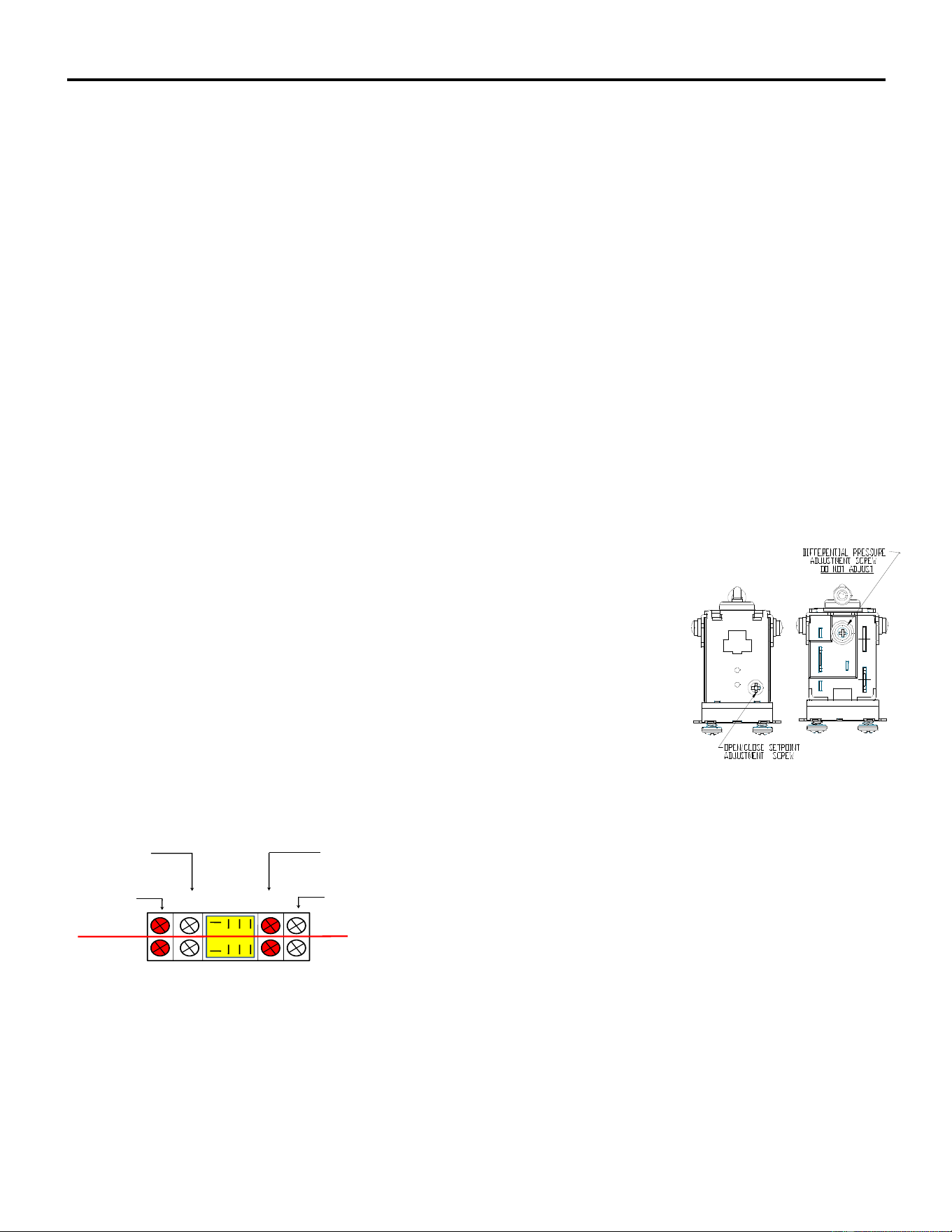
ICE Series Electrical System
Page F3
Untimed Freeze Cycle
During the freeze cycle the compressor, water pump and condenser fan motor(s) (if used) are running. On
remote systems the liquid line solenoid is also energized, see Refrigeration System. As ice forms on the
evaporator, the suction pressure drops. The machine is in the untimed portion of the freeze cycle and will
remain in untimed freeze until the suction pressure drops low enough to close the timer initiate control. See
page I1-I6 for operating pressures.
Timer Initiate
The timer initiate is a low-pressure control that closes (cut in) on a drop in suction pressure. When the timer
initiate control closes, the freeze timer is energized and the machine enters the timed portion of the freeze
cycle. When the machine enters harvest, the suction pressure rises and opens the control. The timer
initiate control should be adjusted per the chart on page I1-I6.
The timer initiate is factory set and does not normally need to be adjusted. If the ice bridge thickness is
incorrect, the freeze timer should be adjusted rather than the timer initiate. See page F4 for freeze timer
adjustment procedure. The timer initiate may need to be adjusted if excessive time (more than 7 minutes)
is needed on the timer to achieve proper bridge thickness of if very little time (less than 1 minute) is needed
on the timer to achieve proper bridge thickness.
If the timer initiate is suspected of being out of adjustment or not operating properly, check the control as
follows. Make sure the high temperature safety control is not open, see page F8. Turn the machine off and
disconnect incoming power by unplugging the machine or switching the circuit breaker OFF. Attach one
lead of a voltmeter to terminal 1 and the other lead to terminal 2 of the timer initiate control.
Reconnect incoming power and turn the machine to the ICE position. Connect a low pressure
gauge to the machine. The volt meter should read line voltage until the timer initiate
control closes at which point the voltmeter should read zero volts. Note the
suction pressure at this point. Adjust the timer initiate if necessary. Turning the
adjustment screw counter clockwise will lower the cut in pressure, turning the
adjustment screw clockwise will raise the cut in pressure. The differential is
preset and does not require adjustment. If the control cannot be adjusted to the
correct pressure setting or if the cut in point is erratic the control must be
replaced. If the suction pressure is not dropping properly, see the
Troubleshooting Tree “Machine Does Not Enter Harvest” in Section C.
Relay 1
Relay 1 is used to energize the fan motor on air-cooled units. The fan is energized through the common
and normally closed contacts.
COMMON
COIL
NORMALLYCLOSED
N.C.
NORMALLYOPENED
N.O.
12
9
14
13
4
1
8
5
A
B
Relay 2 (Note: Relay 2 is not used on Undercounter models)
On single evaporator machines, relay 2 is used only to bypass the bin control during the freeze cycle and
the first part of the harvest cycle. Relay 2 is energized through the normally closed contacts of the cam
switch at the beginning of the freeze cycle. When energized, Relay 2 will prevent the machine from shutting
off if the bin switch opens. The relay will remain energized until the cam switch is lifted onto the high part of
the cam during harvest. At this time the machine will shut off if the bin switch is open.
Relay 3 and Relay 4 (ICE1506 Applications) Relay 3 and Relay 4 bypass the bin switches to allow the
curtains to open and close during the freeze cycle on an ice dispenser application. This will prevent the ice
machine from shutting off during dispenser agitation.
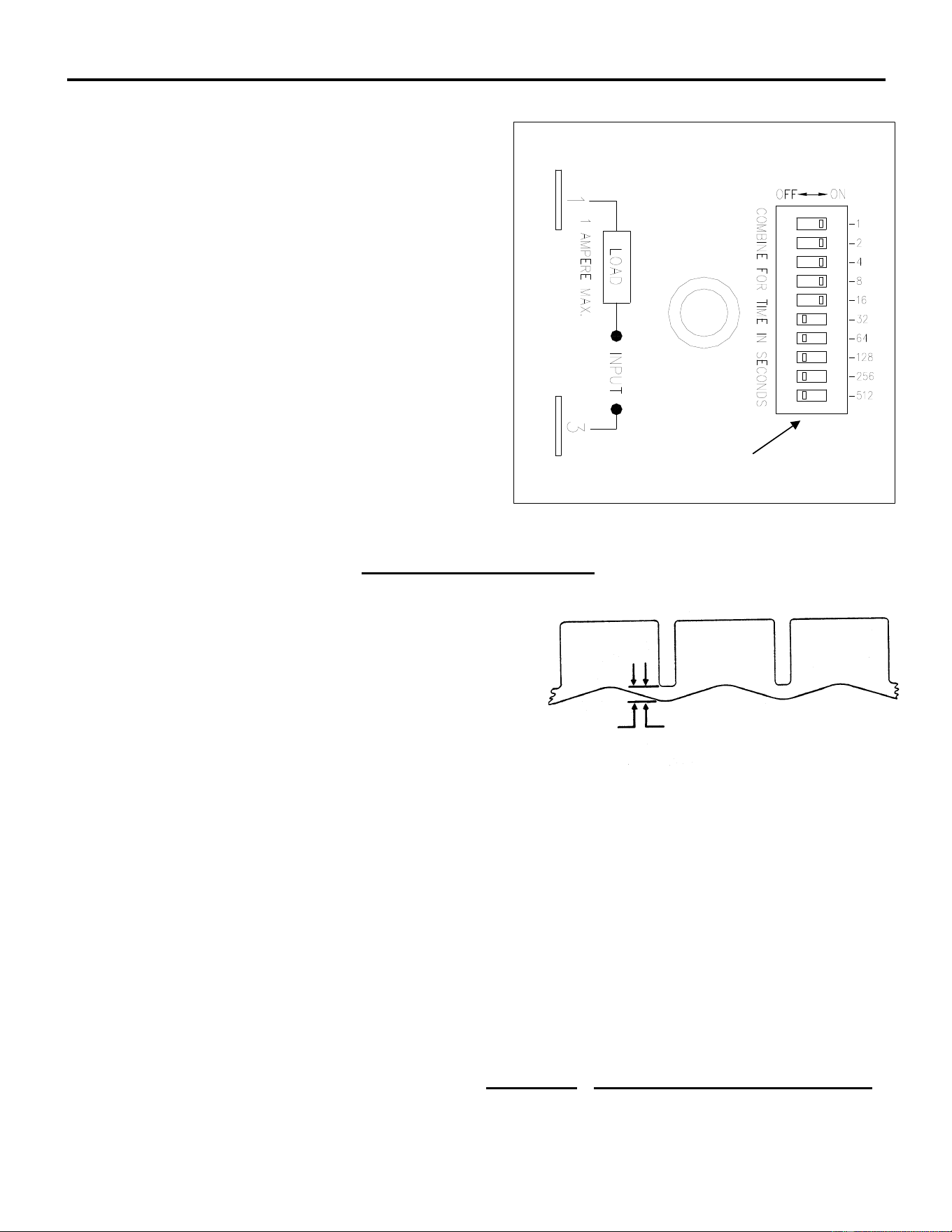
ICE Series Electrical System
Page F4
Timed Freeze
When the freeze timer is energized, the machine
is in the timed portion of the freeze cycle. The
freeze timer will time out the remainder of the
freeze cycle. Once the time has passed, the
machine will enter the harvest cycle.
Freeze Timer
The freeze time is an adjustable timer used to
control the ice bridge thickness. The freeze timer
is factory set but may need to be adjusted upon
initial start up of the machine. When time is
added to the freeze timer, the length of the freeze
cycle is increased, therefore the ice bridge
thickness is increased. When time is removed
from the timer, the freeze cycle is decreased and
the ice bridge thickness is decreased.
The freeze timer can be adjusted by sliding one
or more switches to either the ON or OFF
position to obtain the setting which will produce the proper bridge thickness.
The factory initial timer settings are 64 and 128 for a Half Cube and 128 and 256 for a Full Cube.
The ice bridge thickness should be approximately 3/16”
(5mm) on the ICEU undercounter series, ICE0250 and
ICE0305, and 1/8” (3 mm) on ICE0400 and larger units.
If the bridge is too thick, remove enough time from the
timer to achieve proper thickness. If the bridge is too
thin, add enough time to the timer to achieve proper
thickness.
Check the freeze timer for proper operation as follows: Make sure that the high temperature safety
control is not open, see page F8. Turn the machine OFF and disconnect the incoming power by
unplugging the machine or switching the circuit breaker OFF. Attach one lead of a voltmeter to
terminal 1 and the other lead to terminal 3 of the timer.
Reconnect incoming power and turn the machine to the ICE position. The volt meter should read
zero volts until the timer initiate closes at which point the timer will energize and line voltage should
be read.
When the timer counts out, the voltmeter will again read zero volts. The time it takes the freeze
timer to time out, once it has been energized should match the timer adjustment. If it does not or if
the timer never closes, the timer is defective.
Note: The hot gas delay timer utilized on the ICE1400, ICE1506, ICE1606, ICE1800 and
ICE2100 Series cubers should always be set at 4 seconds. (Not applicable on Version 3 & 4)
Bridge Thickness
Combine time in seconds
Sam
p
le Time
r

ICE Series Electrical System
Page F5
Harvest Cycle
Single Evaporator Machines
Once the freeze timer has timed out, power is sent to relay 1 and the machine enters the harvest
cycle. Once in harvest, the purge valve, hot gas valve and harvest motor are energized. The
water pump continues to run during the first part of the harvest cycle so that mineral laden water
remaining in the water trough can be pumped through the purge valve to the drain. The harvest
motor turns the clutch assembly to actuate the cam switch.
The cam switch is in the normally closed position during freeze and at the beginning of harvest.
Once the clutch turns far enough to actuate the cam switch, the water pump and purge valve is de-
energized. The harvest motor continues to turn the clutch. When the cam switch returns to the
normally closed position, the machine returns to the freeze cycle.
If the bin switch is open when the cam switch is actuated by the high part of the cam, the machine
will shut off. Remote units pump down before shutting off.
Relay 1
When relay 1 is energized, the normally open contacts (1-B) close sending power to the hot gas
valve and harvest motor and (1-A) close sends power to the purge valve and the coil of relay 1 to
keep the coil energized when the timer initiate opens. The fan motor on self contained air cooled
model are wired through the NC contacts of relay 1, when the contacts open during harvest, the
condenser fan motor is de-energized.
Note: The operation of the Hot Gas Valve and Water Pump vary by model number, reference
the wiring diagram on the specific model number for operation sequence.
Relay 2 See Page F3.
Dual Evaporator Machines (Prior to Jan 08)
Once the freeze timer has timed out, power is sent to: (A) harvest motor 1 and relay coil 1 through
the normally closed contacts of cam switch 1, (B) to harvest motor 2 and relay coil 2 through the
normally closed contacts of cam switch 2. The contacts of relay 1B and 2B closing, energizes the
4-second hot gas delay timer (Right Hand Timer)
This 4-second delay will allow the harvest motors to rotate and allow the cam switches to switch to
the normally open position before the low-pressure control opens during hot gas. The cam
switches are now in the normally open position and will continue to energize the harvest motors
and relays until the cam rotates and the switch returns to the normally closed position.
Once the 4-second delay timer has timed out, the hot gas valves and purge valve will energize
and allow hot gas into the evaporators. The bin control switches are by passed through the
normally open contacts of relay 1A and 2A.
The bin switches are bypassed to allow the cam switch to return to the normally closed position
prior to the machine shutting down if the curtain is open. Each harvest assist motor will only make
one revolution prior to shutting down on full bin or advancing to the next freeze cycle.
Both hot gas valves and the water purge valve remain energized until both harvest assist motors
complete one revolution. The water pump is energized throughout the harvest cycle. The unit will
shut down if the curtains are open during the freeze cycle. Remote units pump down before
shutting off. The fan motors on self contained air cooled model are wired through the NC contacts
of relay 1B, when the contacts open during harvest, the condenser fan motors are de-energized.
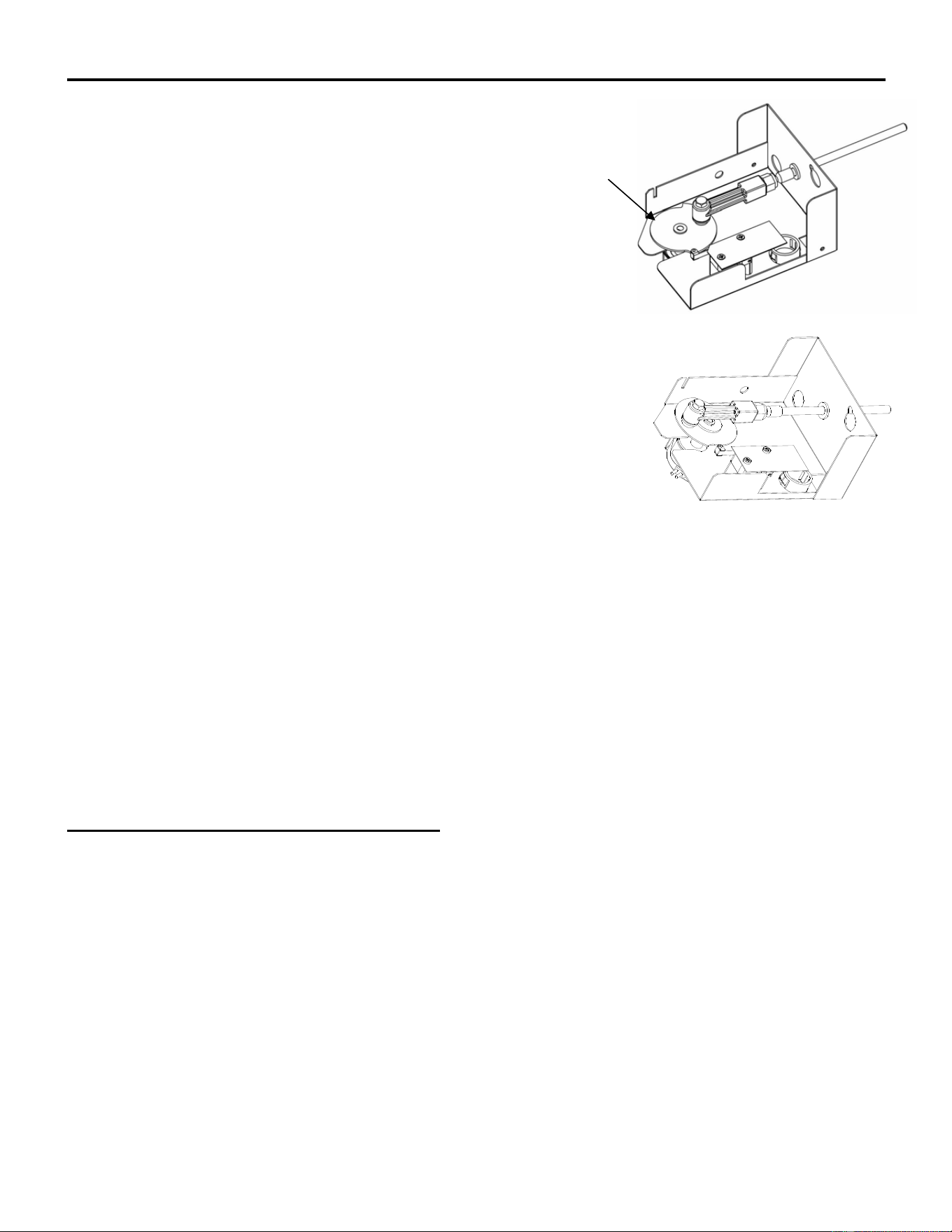
ICE Series Electrical System
Page F6
Harvest Assist Assembly*
*Note: Harvest Assist Assemblies factory installed from Serial
Number 1507 utilize a cam only and a synchronous motor.
Service parts are not available for both configurations; the
complete assembly must be replaced.
The harvest assist assembly has several purposes: to assist in
moving the ice off of the evaporator, to control purge duration,
control the length of harvest and to terminate harvest. When the
machine enters harvest, power is sent to the harvest motor which
turns a slip clutch*. A probe is attached to the rotating clutch* and
is pushed against the back of the ice slab. The clutch* begins to
slip when the probe applies approximately 25 ounces of pressure
against the ice slab.
It takes approximately 1 minute for hot gas to heat the evaporator
enough to loosen the ice from the evaporator plate. At this point the
clutch* pressure overcomes the capillary attraction of the ice to the
evaporator plate and the ice begins to move off of the evaporator.
As the ice is being pushed, the clutch stops slipping and begins to turn, extending the probe
enough to push the ice completely off of the evaporator.
Harvest Motor*
The harvest motor is energized at the beginning of harvest and will remain energized until the
machine returns to the freeze cycle. A defective harvest motor will usually not run. The harvest
motor rotates in a clockwise direction. It is possible for a defective motor to run backwards
(counterclockwise). If this happens the motor must be replaced. It is also possible for a defective
motor to “bump” backwards immediately when entering harvest. This will activate the cam switch
and cause the machine to return to the freeze cycle immediately after entering harvest. If the
machine is in harvest only for a split second, the harvest motor may be defective. Verify the motor
is defective by watching the clutch* closely when the machine enters harvest.
Clutch Assembly*-Pre 1507 Serial Number
The clutch assembly consists of a slip clutch* and cam. A probe is attached to the clutch*
assembly and the harvest motor turns the clutch* during harvest. As the harvest motor turns, the
clutch* will slip while the probe is pushed against the ice. The clutch* will continue to slip as long
as the pressure required to move the ice is greater than the 25 oz. Once the evaporator has
heated enough to break the bond of ice to the evaporator, the pressure required to move the ice
becomes less than the 25 oz. and the clutch* begins to move.
The clutch* assembly is not adjustable. If the clutch* tension is weak (less than 25 oz.) a slow
harvest or excessive ice meltage during harvest will result. If the clutch* pressure becomes too
tight, the force of the probe against the back of the ice may cause the slab to break and the ice
may not fall off of the evaporator. If the clutch tension is suspected of being too tight or loose, turn
the clutch by hand. The clutch* should turn smoothly without “grabbing”, but should offer some
resistance. If in doubt as to whether or not the clutch* is defective, compare the tension with one
that is known to be good.
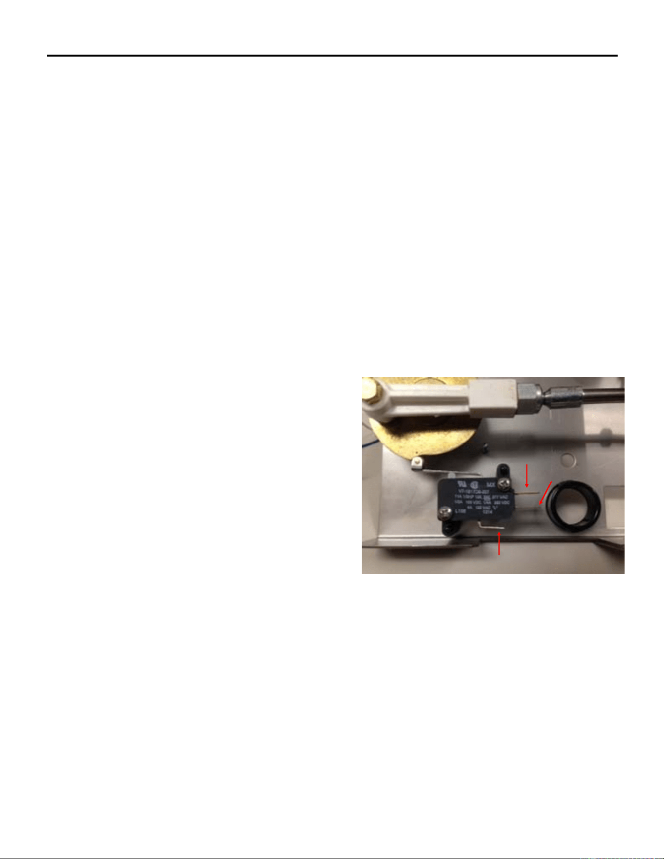
ICE Series Electrical System
Page F7
CommonTe r m i n a l
N.O.Contact
N.C.Contact
*Note: Harvest Assist Assemblies factory installed from Serial Number 1507 utilize a cam
only and a synchronous motor. Service parts are not available for both configurations; the
complete assembly must be replaced.
Probe Tip and Swivel
The probe tip is attached to the clutch* and makes contact with the back of the ice slab during harvest. The
swivel allows the probe tip to pivot as the clutch* turns so that the probe is pushed straight through the
evaporator probe guide.
The tip of the probe should be flush with the back of the evaporator or recessed up the 1/16 of an inch
(.16cm). The probe tip must not extend into the freezing area of the evaporator during freeze.
(Note: Units manufactured after June 2004 utilize a non adjustable probe.)
The length of the probe is adjustable by loosening the locknut and adjusting the probe in or out of the
swivel. Once the probe has been adjusted to the proper length, tighten the locknut. If the probe tip binds
during operation it may cause the clutch* to slip unnecessarily. This may occur if the harvest motor
mounting bracket is not aligned properly or if the probe tip has excessive mineral deposits on it. Remove
and clean the probe if necessary.
To check the probe tip for binding, remove the shoulder bolt holding the swivel to the clutch* and simulate
the movement of the swivel and probe by moving the swivel in a circular motion around the outer portion of
the clutch*. The swivel should also move freely. If any resistance is felt the bracket should be adjusted by
loosening the bracket mounting screws and repositioning the bracket until the probe moves freely.
Cam Switch Operation-Single Evaporator Machines
The actuator arm of the cam switch rides on the edge of
the clutch* assembly and is actuated by the high and low
portion of the cam. When the machine is in the freeze
cycle the actuator arm of the cam switch is in the low part
of the cam. During freeze, power is supplied to the water
pump and relay 2, through the normally closed contacts
of the cam switch. When the machine enters harvest,
power is supplied to the water pump and purge valve
through the normally closed contacts of the cam switch
and through the normally open contacts of relay 1 (closed
during harvest). The water pump, purge valve and relay
1 remain energized until the cam switch is lifted on to the
high part of the cam. Relay 2 will also de-energize at this
time allowing the machine to shut off if the bin switch
opens. Undercounter machines manufactured after July
of 2004 will have the water pump run continually until the machine shuts down.
Cam Switch Operation-Dual Evaporator Machines (Prior to January 2008)
Once the freeze timer has counted out, power is sent to: (A) harvest motor 1 and relay coil 1 through the
normally closed contacts of cam switch 1, (B) to harvest motor 2 and relay coil 2 through the normally
closed contacts of cam switch 2.
This 4-second delay will allow the harvest motors to rotate and allow the cam switches to switch to the
normally open position before the low-pressure control opens during hot gas. The cam switches are now in
the normally open position and will continue to energize the harvest motors and relays until the cam rotates
and the switch returns to the normally closed position
.
The bin switches are bypassed to allow the cam switch to return to the normally closed position, prior to the
machine shutting down if the curtain is open. Each harvest assist motor will only make one revolution prior
to shutting down on full bin or advancing to the next freeze cycle. Both hot gas valves and the water purge
valve remain energized until both harvest assist motors complete one
revolution. The water pump is

ICE Series Electrical System
Page F8
Cam Switch Adjustment
Check the cam switch for proper adjustment by slowing turning the clutch by hand in a
counterclockwise direction while listening for the switch contacts to change. The switch should
have an audible “click” as the roller reaches the high part of the cam. Now slowly turn the clutch in
a clockwise direction and the switch should have an audible “click” as the roller reaches the low
part of the cam. Units manufactured from June of 2004 do not utilize an adjustable cam
switch. If the cam switch is suspected of being defective it should be checked with an ohmmeter.
It should not be assumed that the switch is good because a “click” can be heard when
moving the actuator arm.
Note: Harvest Assist Assemblies factory installed from Serial Number 1507 utilize a cam
only and a synchronous motor. Service parts are not available for both configurations; the
complete assembly must be replaced.
High Temperature Safety Control
The high temperature safety control is a thermal disc that protects the
machine if the machine “sticks” in the harvest cycle. The high temperature
safety is clamped to the suction line near the expansion valve thermal bulb.
It opens when the suction line temperature reaches 120ºF (48.8ºC) and
closes when the temperature drops to 80ºF (26.6ºC). If the high temperature safety opens during
harvest, it will de-energize the harvest components. If the high temperature safety is defective and
fails open during the freeze cycle, it will not allow the relay(s) to energize and the machine will not
enter harvest. Remove the high temperature safety control and check it with an ohmmeter to verify
that it is defective.
Note 1: ICE0500R3, ICE0606R3, ICE0806R3 and ICE1006R3: The high temperature safety
control specifications have been changed to open at 120 ْ◌ F and close at 100 ْ◌ F.
Note 2: On models where the high temperature safety control is mounted on the hot gas valve
outlet tube, the specifications are open at 180ºF and close at 120 ºF.
Additionally the high temperature safety control is wired in series with the contactor. If the
high temperature safety control opens for any reason, the compressor will shut down.
This is an automatic reset control. Do not allow the machine to operate without the
high temperature safety control. Damage to the machine may result and the
warranty will be void.
Bin Control Operation
The bin control is used to shut the machine off when the bin fills with ice. The bin control must be
checked upon installation or initial start-up and when performing maintenance. Adjustments are
not covered under warranty.
There is one bin switch for each evaporator. The actuator arm of the bin switch comes in contact
with the splash curtain. When the bin is full of ice, the splash curtain is held open when ice drops
off of the evaporator. This releases the pressure of the bin switch actuator arm allowing the switch
to open.
Single evaporator machines: If the bin switch opens during freeze, or the first part of harvest,
relay 2 bypasses the bin switch and the machine will continue running. If the bin switch is opened
during harvest, when the cam switch is lifted onto the high part of the cam, the machine will shut
off. When the bin switch closes again, the machine will restart.
Dual evaporator machines: If either bin switch opens during the freeze cycle, the machine will
shut off. Relay 1 and relay 2 will bypass the bin switches during defrost. If either bin switch is
open when the machine returns to the freeze cycle, the machine will shut off.

ICE Series Electrical System
Page F9
Undercounter machines: A thermostatic bin control is used on the undercounter models. The bin
thermostat is located in the control box with a capillary tube, which is in a brass thermo-well mounted to the
water trough or right side of the bin. When ice comes in contact with the capillary tube thermo-well, the bin
thermostat opens and the machine will shut off.
Bin Control Adjustment
All Models (Except Undercounter Models): Check the bin switch for proper adjustment by swinging the
bottom of the curtain away from the evaporator. Slowly bring the curtain towards the evaporator. The
switch should close when the bottom edge of the curtain is even with the outer edge of the water trough.
Adjust the switch by loosening the nuts which the hold the switch bracket in place. Move the switch to the
proper position and retighten the nuts. Recheck the adjustment. Adjustments are not covered under
warranty.
Undercounter Models and ICE1506R
The Bin Thermostat used on these Self Contained Ice Cuber Machines is a sensitive device influenced by
ambient conditions including altitude and temperature. The machine is set up to operate properly at the
factory for 70°F at sea level. If your ice machine shuts off early, bin half full, or doesn’t shut off, bin
overflowing, please follow these instructions to set the bin thermostat.
1. These instructions are best followed on a full ice bin with at least 3 inches of ice resting against the
brass thermal well. The machine must be running to perform this adjustment; follow step two if the
machine is off.
2. Turn the thermostat adjustment screw clockwise until it stops; this is the max cold setting and will
prevent the machine from shutting off.
3. Hold a minimum of 3 inches of ice against the middle of the brass thermal well for 3-4 minutes. It is
imperative that enough ice be used for the prescribed time to properly cool the thermostat.
4. Slowly turn the adjustment screw counter-clockwise until the machine shuts off. If the screw is
turned too quickly, the thermostat could be set to too warm a temperature. Turn slowly.
5. Remove the ice from the well and warm the brass with your hand; the machine should turn back on.
The ice machine is now set for ambient conditions. If the ice machine location experiences
significant changes in ambient temperatures, this procedure will need to be followed again.
Adjustments are not covered under warranty.
Pump Down System (Remote Only)
If a remote machine is shut down by the selector switch or bin control, the liquid line solenoid valve is de-
energized allowing the valve to close. This blocks the flow of refrigerant causing all the refrigerant to be
pumped into the receiver and condenser. This is done to prevent liquid refrigerant from migrating into the
compressor during the off cycle, which could damage the compressor on start-up. Also see Pump Down
System in the Refrigeration Section on page E7. As the refrigerant is pumped into the receiver, the suction
pressure begins to drop. Once the suction pressure reaches approximately 10 psi (.68 bar) the pump down
control contacts open, which will de-energize the compressor contactor. When the machine is turned back
on, power is supplied to the liquid line solenoid which opens the valve and allows the suction pressure to
rise enough to close the pump down controls contacts.
Pump Down Control
The pump down control is a low pressure control that shuts the machine off when the suction
pressure drops during the pump down phase. The control is factory set to open at 10 psi (.68 bar)
and close at 35 psi (2.41 bar). The pump down control does not normally need to be adjusted,
however an adjustment may be made by turning the adjustment screw. Note: Later model
machines have a non adjustable pump down control.
Fan Control
On models utilizing a fan control, the fan will cycle on at 250 psi (17.01) and cycle off at
200 psi (13.61 bar).

ICE Series Electrical System
Page F10
Electrical Sequence for the ICE1400 Series Version 3&4, ICE1800 Series Version 3&4 and
the ICE2100 Series Version 3&4 Cubers. (Manufactured from January, 2008)
ICE1400A/W3&4, 1800W3&4 and 2100W3&4 Electrical Sequence (Includes 50 hz. And 3
Phase)
1. Suction Pressure starts out at approx 60 psi and slowly drops to close the LP Control.
2. The LP Control energizes Relay Number 2 Coil.
3. Relay Number 2A contacts C and NO close to bypass the bin switches, Relay Number 2B
contacts close and energize the timer.
4. The Timer times out and energizes Relay Number 1 Coil.
5. Relay Number 1A contacts C and NO close to send power to Cam Switch Number 2 contacts C
and NC which energizes Harvest Motor 2, Hot Gas 2 and Relay Number 3 Coil.
6. Relay Number 1B contacts C and NO close to energize Harvest Motor 1 and Hot Gas 1
7. Relay Number 1B contacts C and NC open to de-energize the fan motors.
8. When the LP Control opens during hot gas, the circuit is latched through the Purge Switch
contacts C and NC.
9. Relay Number 3A contacts C and NO close to send power to the Selector Switch and Hot Gas
Valves when the curtain is open.
10. Once Cam Switch 2 contacts C and NO close (High Side of the Cam) it will remain energized
from the Selector Switch until contacts C and NC close. (Rotates 360 degrees)
11. Once Cam Switch 1 contacts C and NO close (High Side of the Cam) the Harvest Motor will be
energized and the Water Pump and Purge Valve will be de-energized when contacts C and NC
open.
12. With the bin switches open, Relay Number 3 Coil de-energized due to Cam Switch 2 contacts
C and NC closing, the unit will shut off on full bin.
Notes:
●C=Common
●NC=Normally Closed
●NO-Normally Open
●Relay Number 9 & 12=Common
●Relay Number 1 & 4=Normally Closed
●Relay Number 5 & 8=Normally Open
●The Fan Control on the air cooled model cycles only one fan.
●Relay 1, Puts unit into defrosts.
●Relay 2, Bypasses the Bin Switches and initiates the Timer.
●Relay 3, Bypasses the bin Switches during harvest when Relay 2 is de-energized from a rise in
the suction pressure opening the Low Pressure Control.

ICE Series Electrical System
Page F11
Electrical Sequence for the ICE1400 Series Version 3&4, ICE1800 Series Version 3&4 and
the ICE2100 Series Version 3&4 Cubers. (Manufactured from January, 2008)
ICE1400R3&4, 1800R3&4 and 2100R3&4 Electrical Sequence (Includes 50 hz. And 3 Phase)
This unit incorporates a timer upstream of the Low Pressure Control for Low Ambients.
1. Timer number 2 (Six Minutes) is energized from the Selector Switch through Relay Number 3B
contacts C and NC.
2. Timer Number 2 (Six Minutes) times out and energizes Relay Number 2 Coil.
3. Relay Number 2B contacts C and NO close which energizes the Low Pressure Control.
4. The Low pressure Control closes and energizes Timer Number 1.
5. The Timer times out and energizes Relay Number 1 Coil.
6. Relay Number 1A contacts C and NO close to send power to Cam Switch Number 2 C and NC
which energizes Harvest Motor 2, Hot Gas Valve 2 and Relay Number 3 Coil.
7. Relay Number 1B contacts close to energize Harvest Motor 1 and Hot Gas Valve 1.
8. When the Low Pressure Control opens during hot gas defrost, the circuit is latched through the
Purge Switch contacts C and NC.
9. Relay Number 3A contacts C and NO close to send power to the Selector Switch and Hot Gas
Valves when the curtain is open.
10. Once Cam Switch 2 contacts C and NO close (High side of the Cam) it will remain energized
from the Selector Switch until contacts C and NC close. (Rotates 360 degrees)
11. Once Cam Switch 1 contacts C and NO close (High Side of the Cam) the Harvest Motor will be
energized and the Water Pump and Purge Valve will be de-energized when contacts C and NC
open.
12. With the bin switches open, Relay Number 3 Coil de-energized due to Cam Switch 2 contacts
C and NC closing, the unit will shut off on full bin.
Notes:
●C=Common
●NC=Normally Closed
●NO-Normally Open
●Relay Number 9 & 12=Common
●Relay Number 1 & 4=Normally Closed
●Relay Number 5 & 8=Normally Open
●Relay 1, Puts unit into defrosts.
●Relay 2, Bypasses the Bin Switches and initiates the Low Pressure Control
●Relay 3, Bypasses the Bin Switches during harvest when Relay 2 is de-energized from a rise in
the suction pressure opening the Low Pressure Control and energizes Timer Number2

ICE Series Electrical System
Page F12
Electrical Sequence for theICE1506 Series Version 3 (Manufactured from January, 2008)
This unit incorporates a timer upstream of the Low Pressure Control for Low Ambients.
1. When the Selector Switch is set to ICE, Relay Number 2 Coil is energized through Cam Switch
contacts C and NC (Bypasses the Bin Controls)
2. Relay Number 4B contacts C and NC energize Timer Number 2 (6 Minutes)
3. Timer number 2 times out and energizes Relay Number 3 Coil.
4. Relay Number 3B contacts C and NO close and energizes the Low Pressure Control.
5. The Low Pressure Control closes to energize Timer Number 1.
6. Timer Number 1 times out and energizes Relay Number 1 Coil
7. Relay Number 1A contacts C and NO close and send power Cam Switch Number 2 C and NC
which energizes Harvest Motor 2, Hot Gas valves and Relay Number 4 Coil.
8. Relay Number 1B contacts C and NO close to energize Harvest Motor 1 and Hot Gas Valve 1.
9. When the Low Pressure Control opens during hot gas, the circuit is latched through the Purge
Switch contacts C and NC.
10. Once Cam Switch 2 contacts C and NO close (High side of the Cam) it will remain energized
from the Selector Switch until contacts C and NC close (Rotates 360 degrees)
11. Once Cam Switch 1 contacts C and NO close (High side of the Cam) the Harvest Motor will be
energized and the Water Pump, Purge Valve and Relay Number 2 Coil will be de-energized
when contacts C and NC open.
12. When Relay Number 2 Coil is de-energized and if the curtain switches or bin stat are open, the
unit will pump down and shut off on full bin.
Notes:
●C=Common
●NC=Normally Closed
●NO-Normally Open
●Relay Number 9 & 12=Common
●Relay Number 1 & 4=Normally Closed
●Relay Number 5 & 8=Normally Open
●Relay 1, Puts unit into defrosts.
●Relay 2, Bypasses the Bin Switches.
●Relay 3,Energizes the Low Pressure Control
●Relay 4,Resets Timer Number 2

ICE Series Notes
Table of Contents
Table of Contents Page A1
General Information
How To Use This Manual Page A2
Model And Serial Number Format Page A3
Electrical And Mechanical Specifications Page A5-A8
Installation Guidelines Page A9
Electrical And Plumbing Requirements Page A10-A17
Remote Condenser Installation Page A18-A19
How The Machine Works Page A20
Undercounter Model Bin Removal Page A21-A22
Warranty Information Page A23-A24
Scheduled Maintenance
Maintenance Procedure Page B1
Cleaning and Sanitizing Instructions Page B1-B2
Winterizing Procedure Page B3
Cabinet Care Page B4
Troubleshooting Trees
How to Use The Troubleshooting Trees Page C1
Troubleshooting Trees Table Of Contents Page C2
Troubleshooting Trees Page C3-C18
Water System
Water Distribution And Components Page D1-D5
Refrigeration System
Refrigeration Cycle And Components Page E1
Harvest Cycle Page E5
Remote System Page E5-E6
Pump Down System Page E7
Refrigerant Specifications Page E8-E20
Electrical System
Control Circuit Page F1
Compressor And Start Components Page F1-F2
Untimed Freeze Cycle Page F3
Timed Freeze Cycle Page F4
Harvest Cycle Page F5-F9
Pump Down System Page F9
Wiring Diagrams Page G1
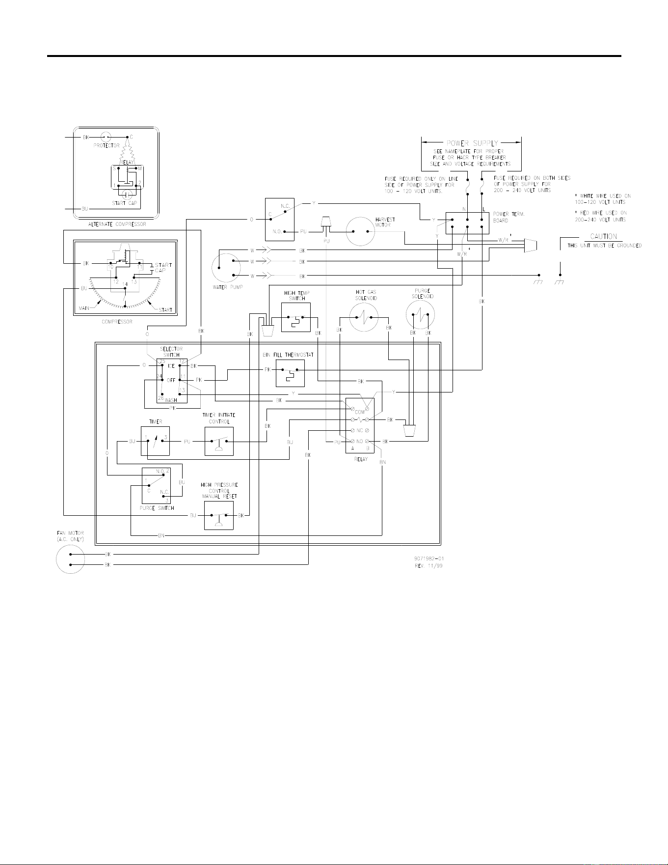
ICE Series Wiring Diagram
Page G1
ICEU150/200/205/206 Air and Water Wiring Diagram
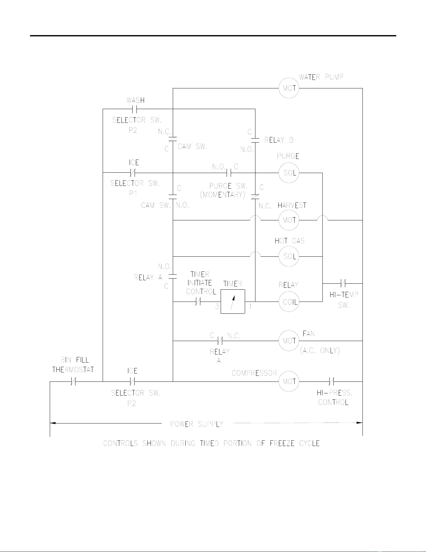
ICE Series Wiring Diagram
Page G2
ICEU150/200/205/206 Air and Water Wiring Schematic
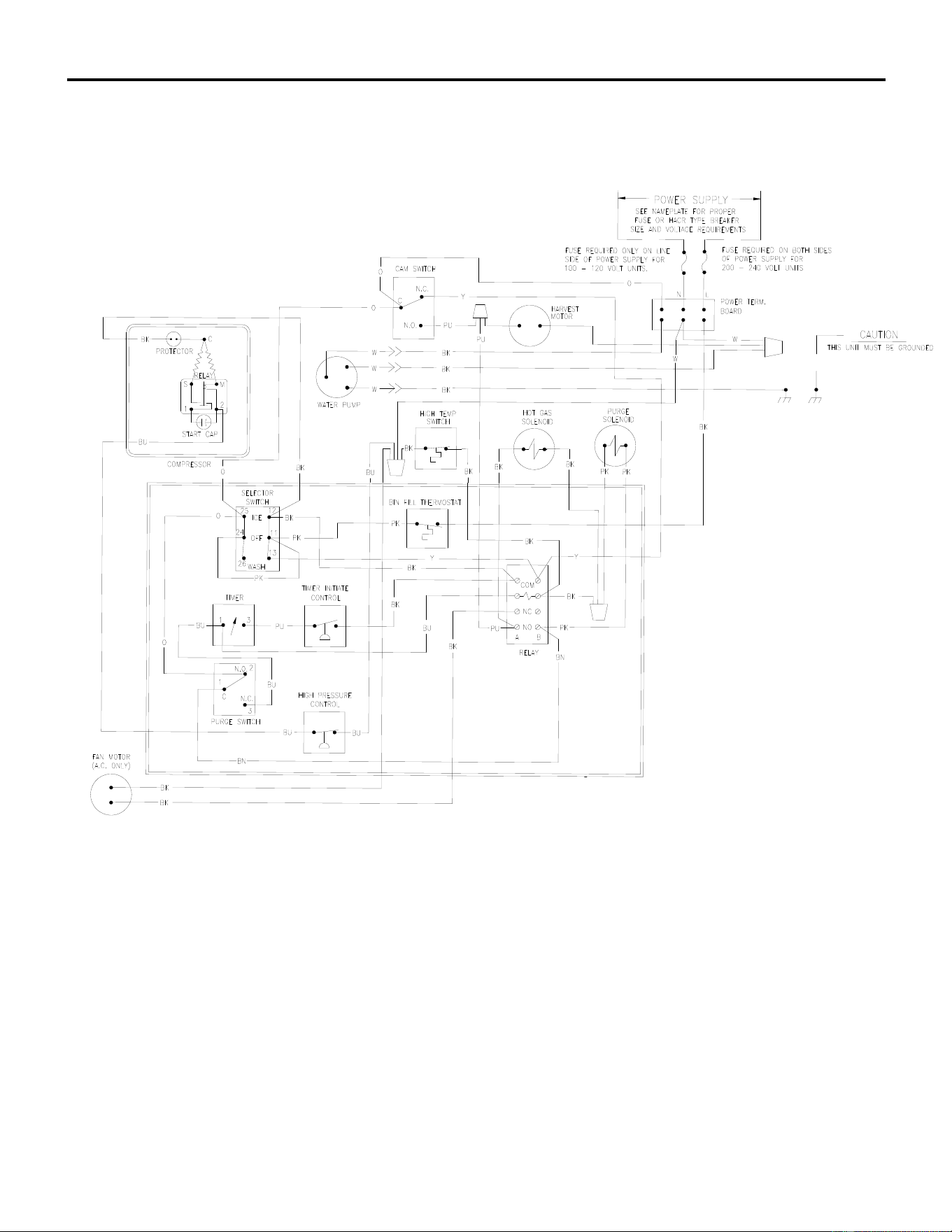
ICE Series Wiring Diagram
Page G3
ICEU150/220/225/226 Air and Water Wiring Diagram
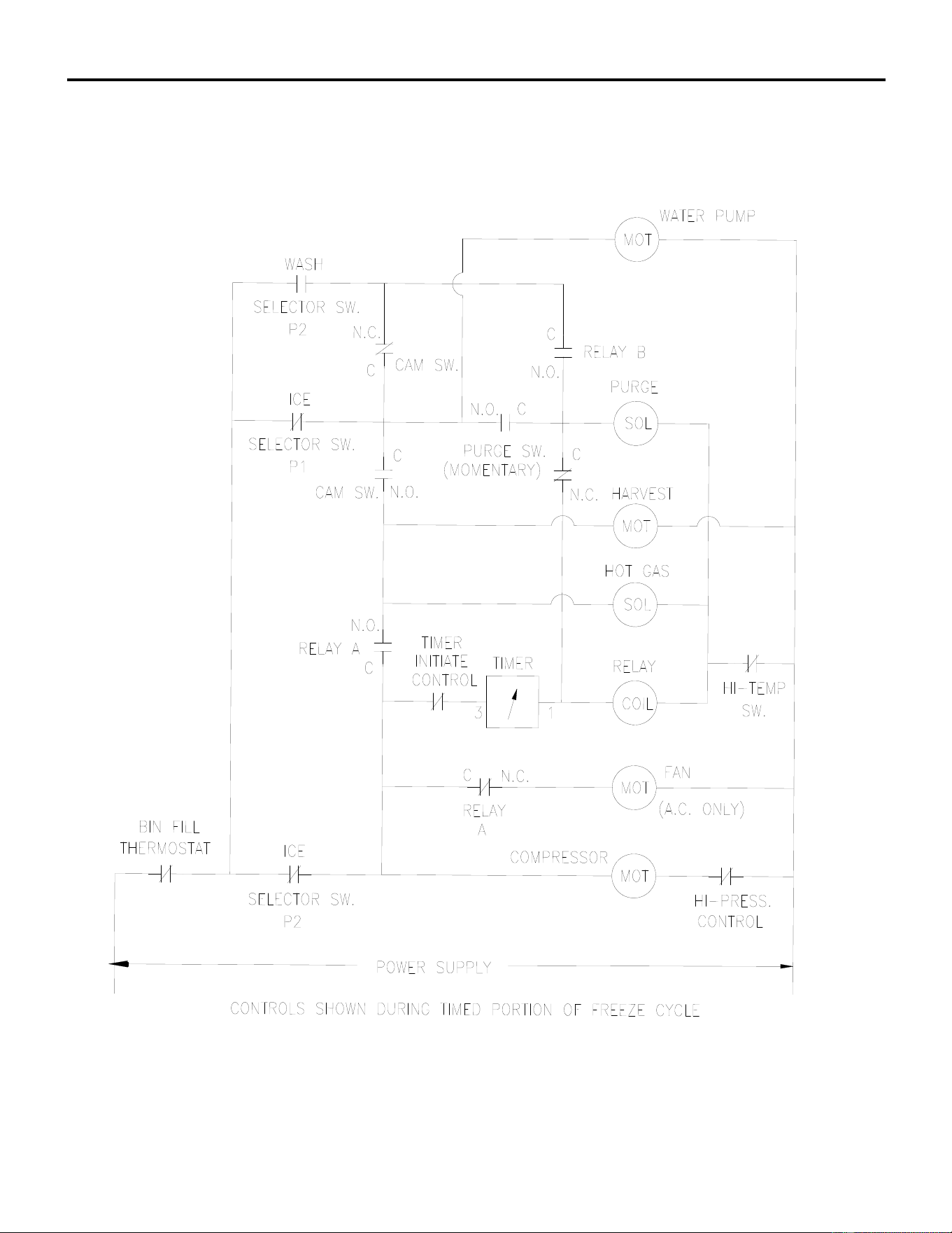
ICE Series Wiring Diagram
Page G4
ICEU150/220/225/226 Air and Water Wiring Schematic
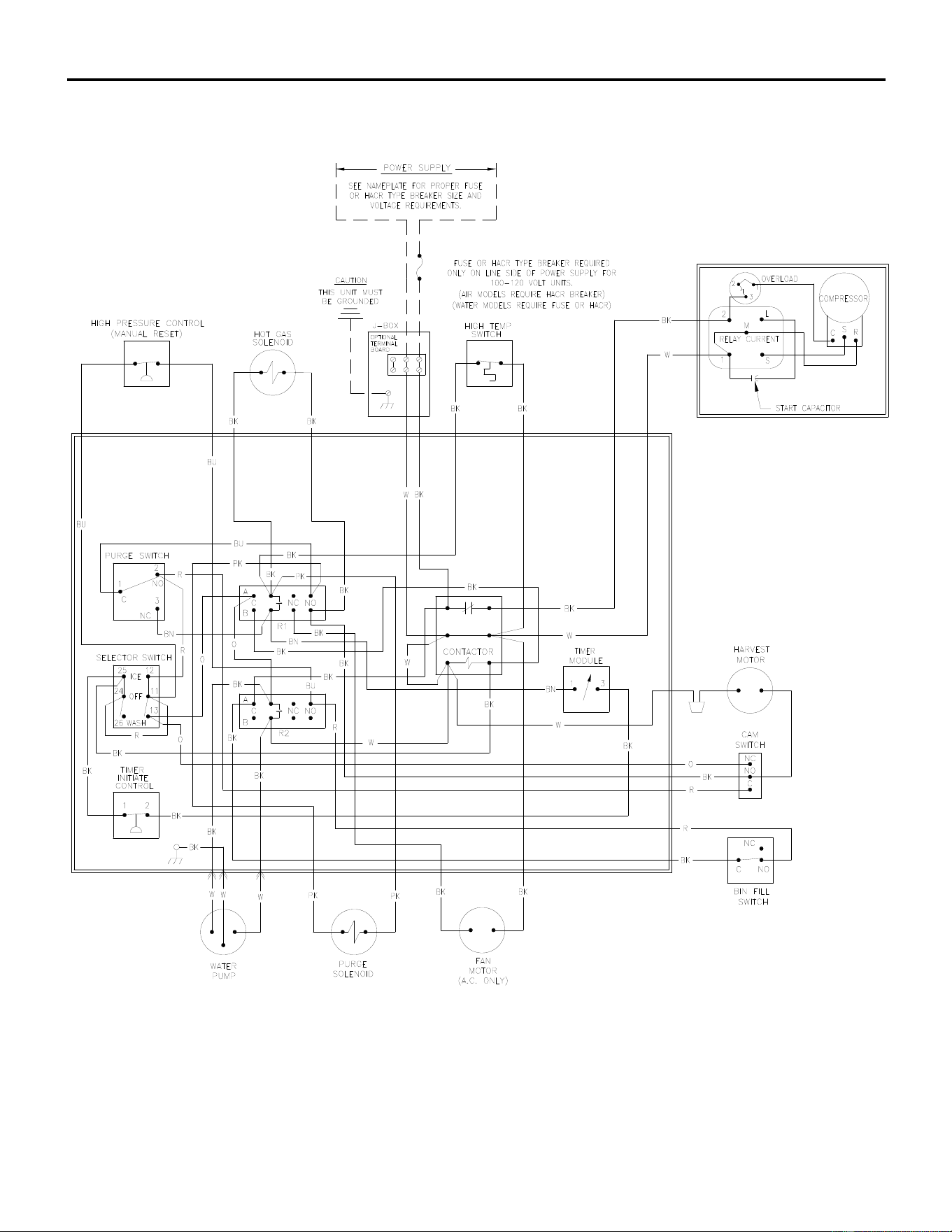
ICE Series Wiring Diagram
Page G5
ICE0250 Air and Water Wiring Diagram
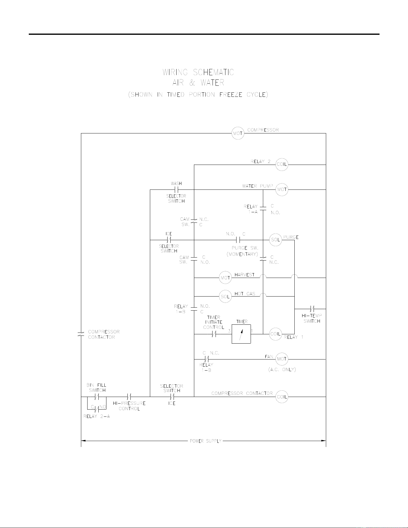
ICE Series Wiring Diagram
Page G6
ICE0250 Air and Water Wiring Schematic
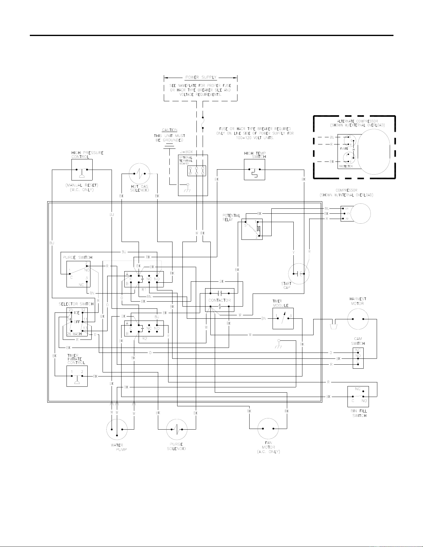
ICE Series Wiring Diagram
Page G7
ICE0400 Air and Water Wiring Diagram
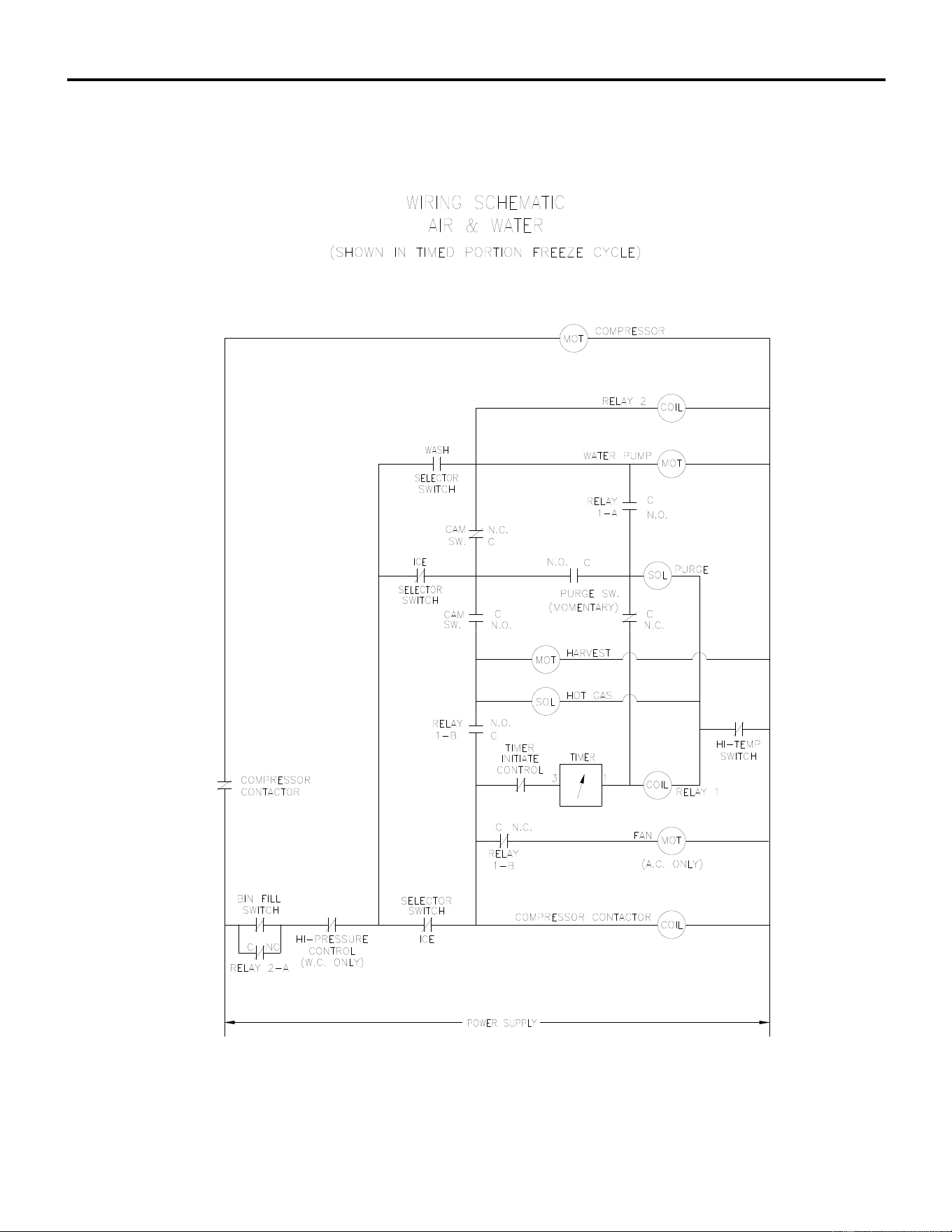
ICE Series Wiring Diagram
Page G8
ICE0400 Air and Water Wiring Schematic
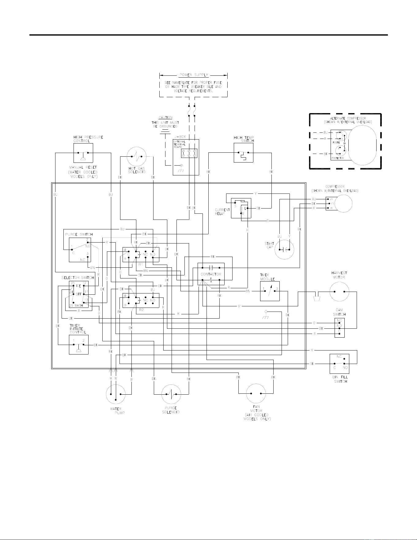
ICE Series Wiring Diagram
Page G9
ICE0405/0406 Air and Water Wiring Diagram
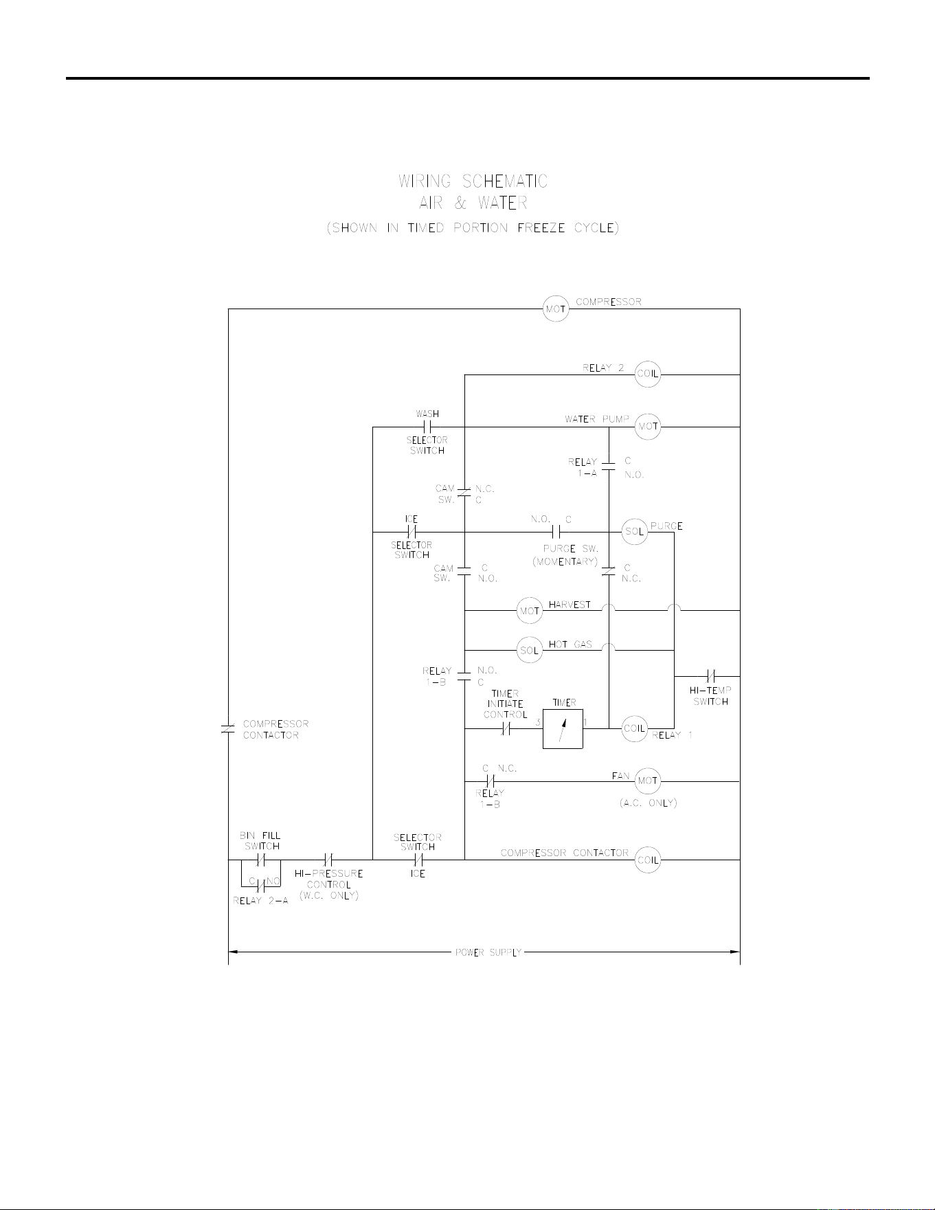
ICE Series Wiring Diagram
Page G10
ICE0405/0406 Air and Water Wiring Schematic
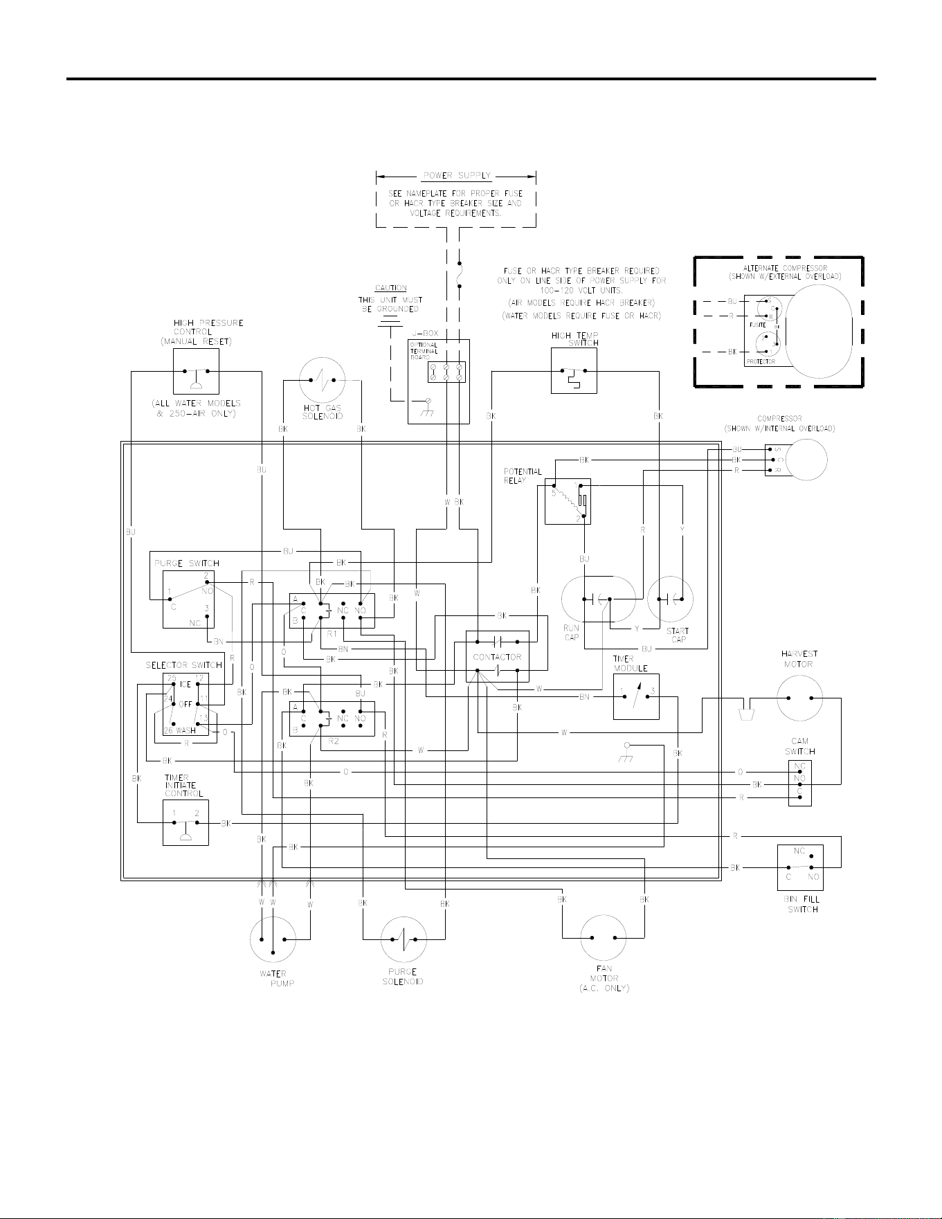
ICE Series Wiring Diagram
Page G11
ICE0500 Air and Water Wiring Diagram
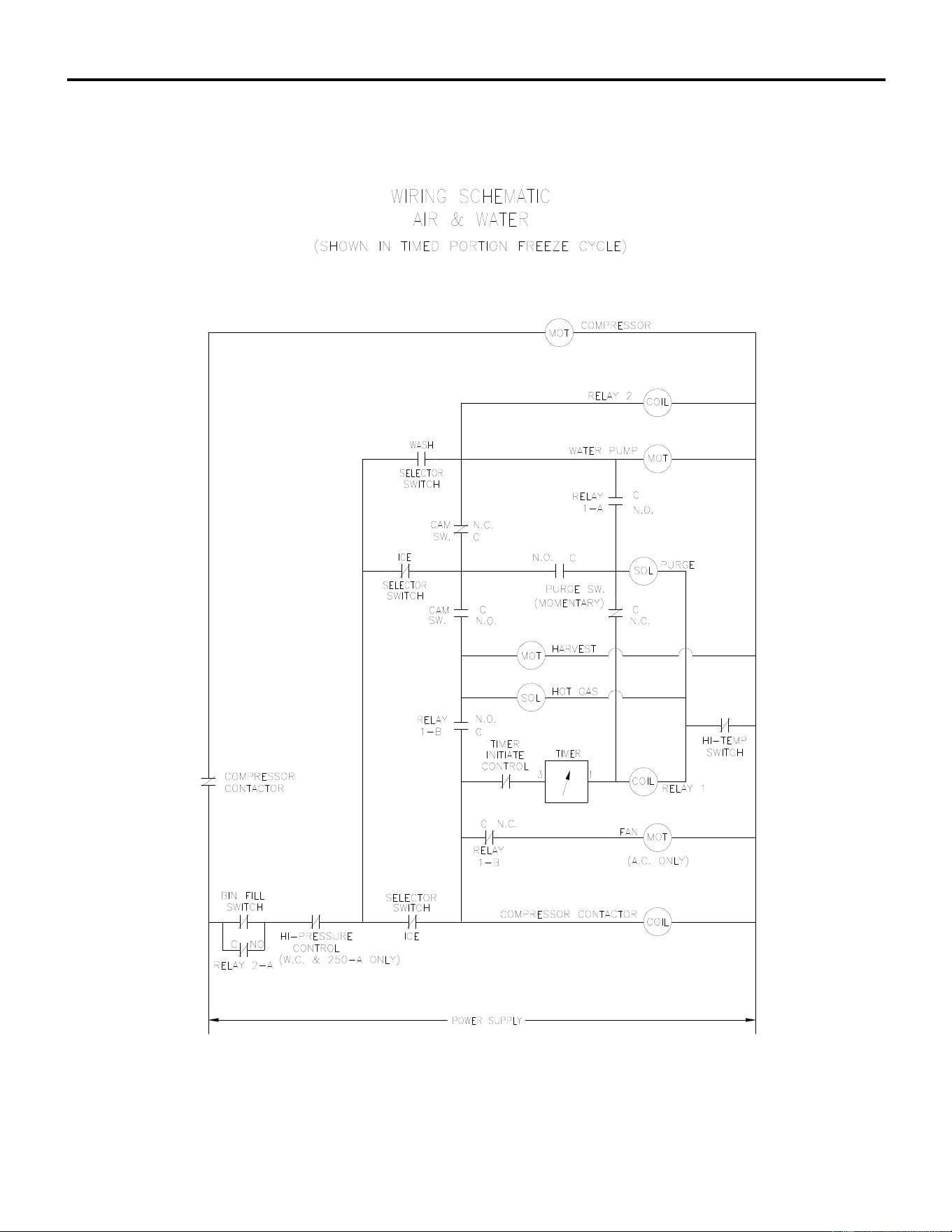
ICE Series Wiring Diagram
Page G12
ICE0500 Air and Water Wiring Schematic
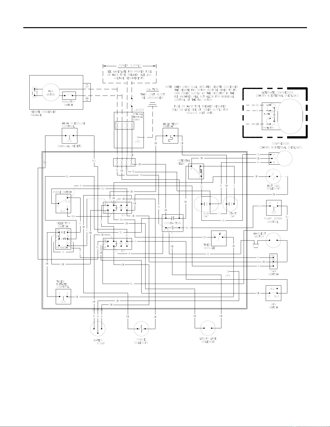
ICE Series Wiring Diagram
Page G13
ICE0500 Remote Wiring Diagram
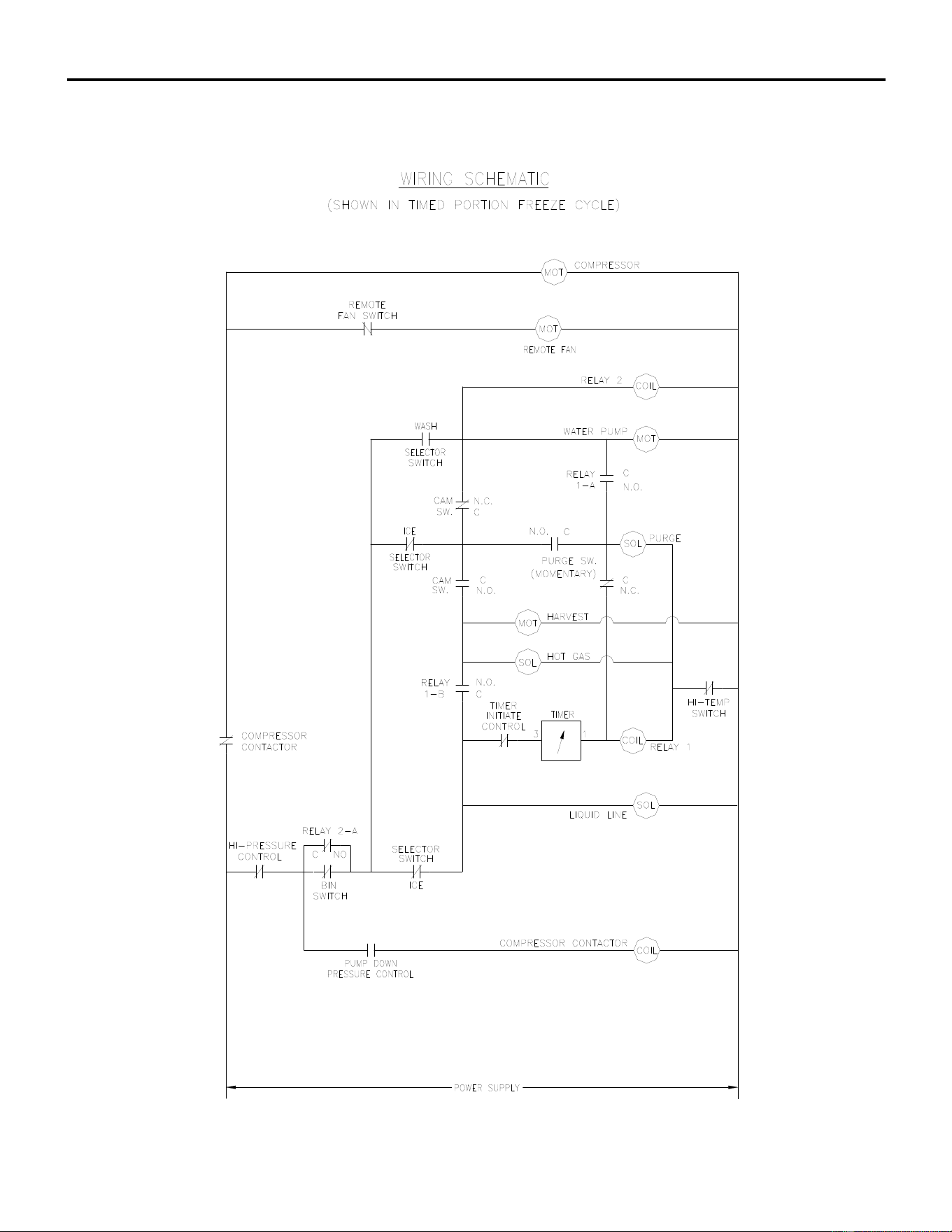
ICE Series Wiring Diagram
Page G14
ICE0500 Remote Wiring Schematic
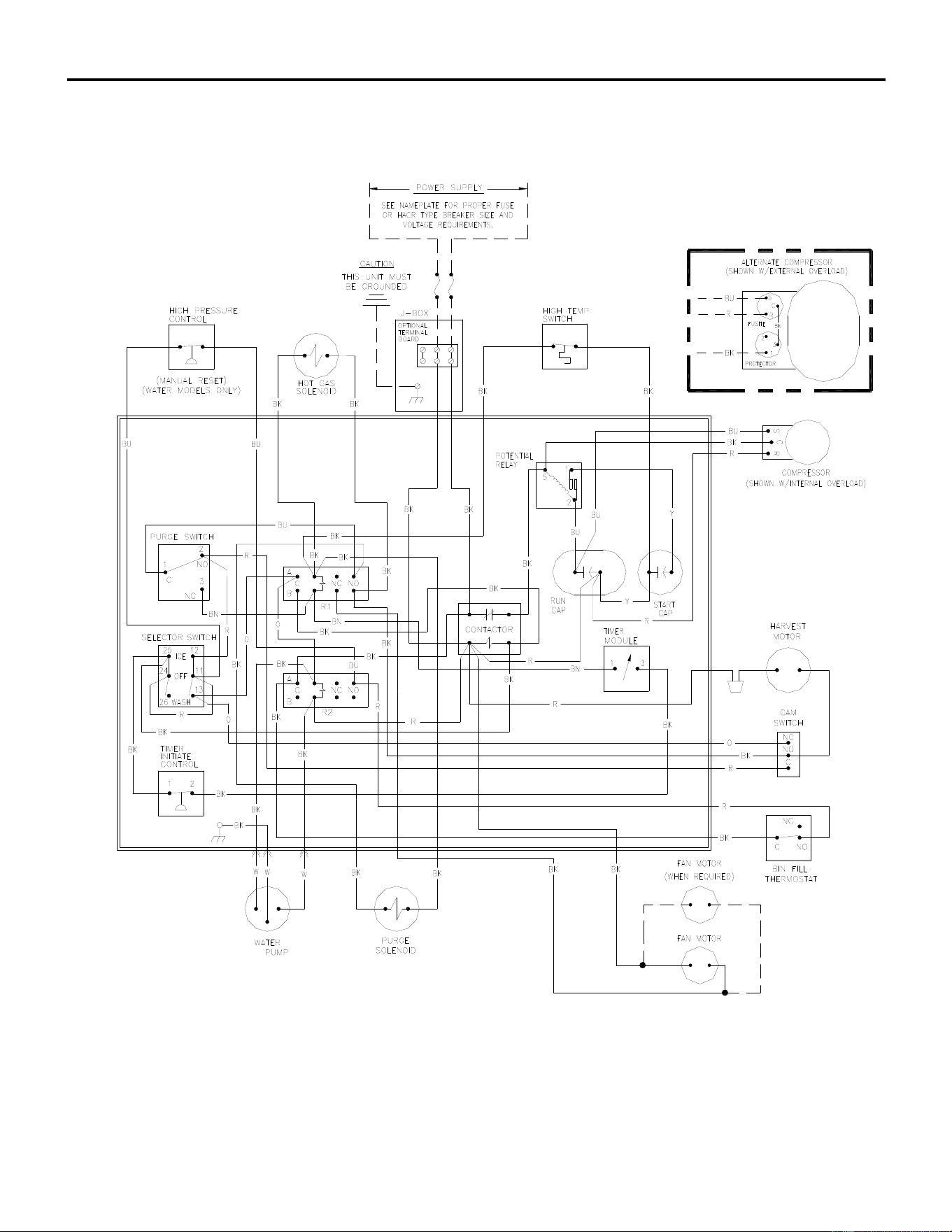
ICE Series Wiring Diagram
Page G15
ICE0605/0606/0805/0806/1005/1006 Air and Water Wiring Diagram
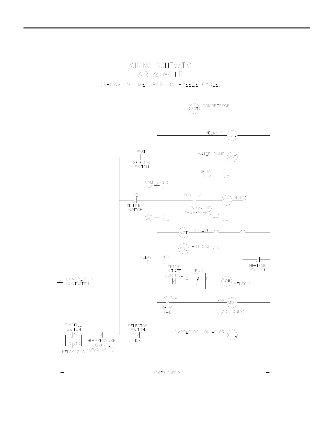
ICE Series Wiring Diagram
Page G16
ICE0605/0606/0805/0806/1005/1006 Air and Water Wiring Schematic
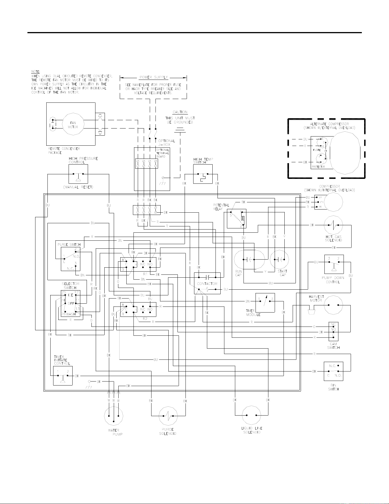
ICE Series Wiring Diagram
Page G17
ICE0605/0606/0805/0806/1005/1006 Remote Wiring Diagram
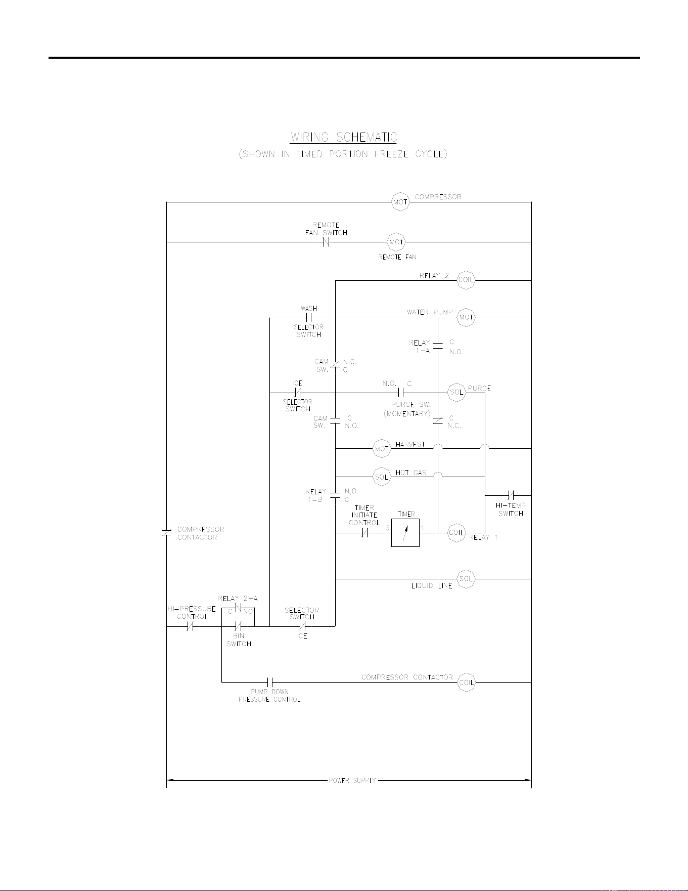
ICE Series Wiring Diagram
Page G18
ICE0605/0606/0805/0806/1005/1006 Remote Wiring Schematic
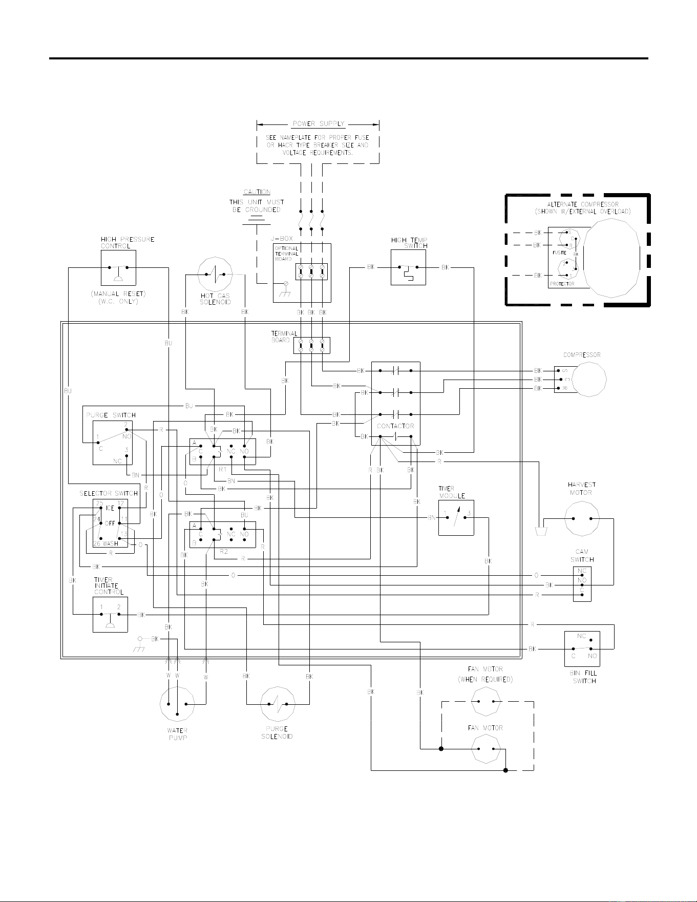
ICE Series Wiring Diagram
Page G19
ICE1007 Air and Water Wiring Diagram
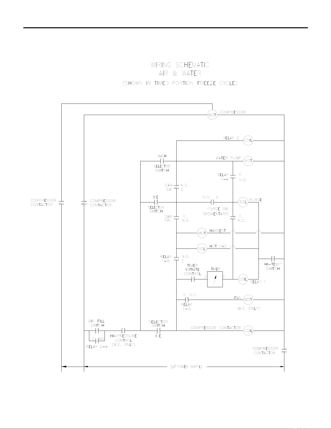
ICE Series Wiring Diagram
Page G20
ICE1007 Air and Water Wiring Schematic
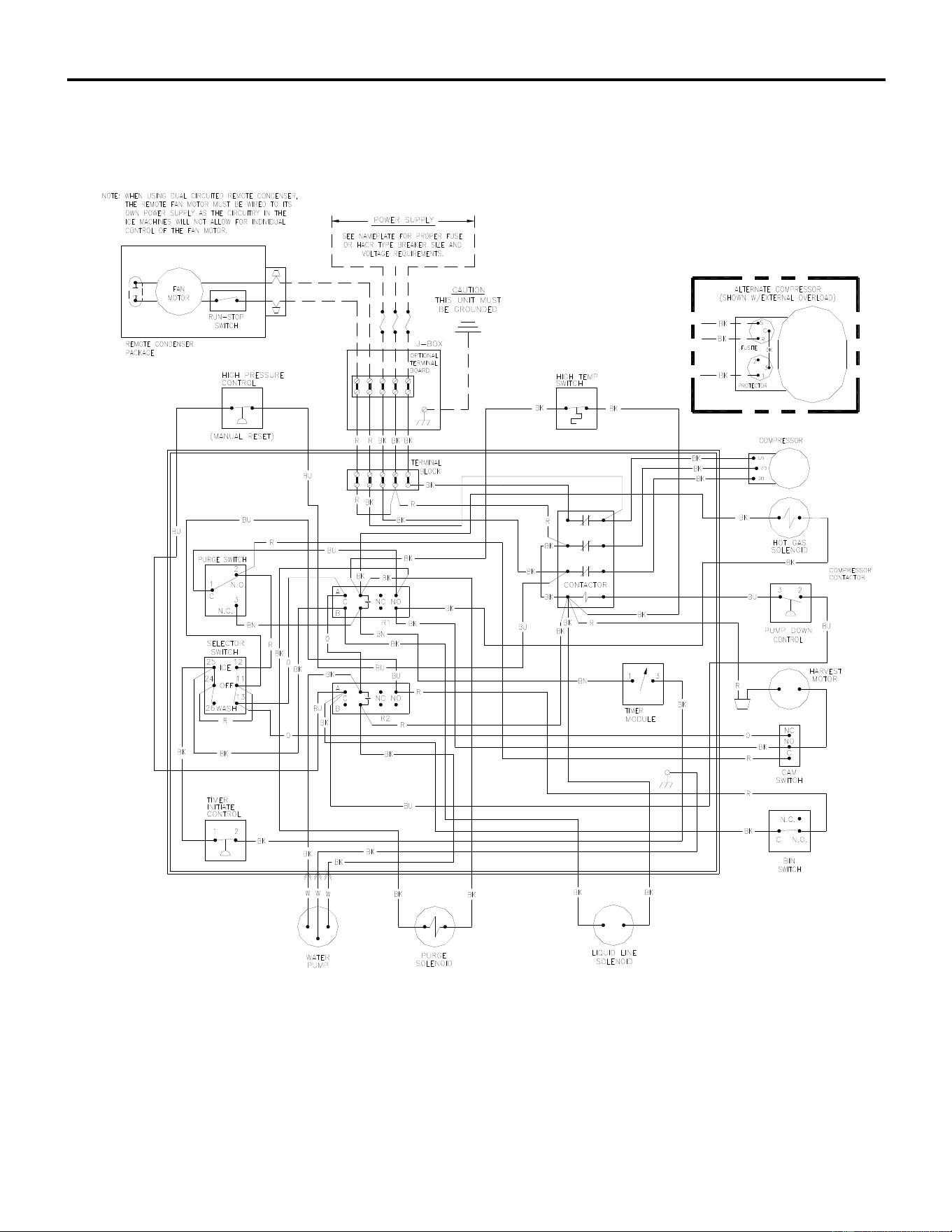
ICE Series Wiring Diagram
Page G21
ICE1007 Remote Wiring Diagram
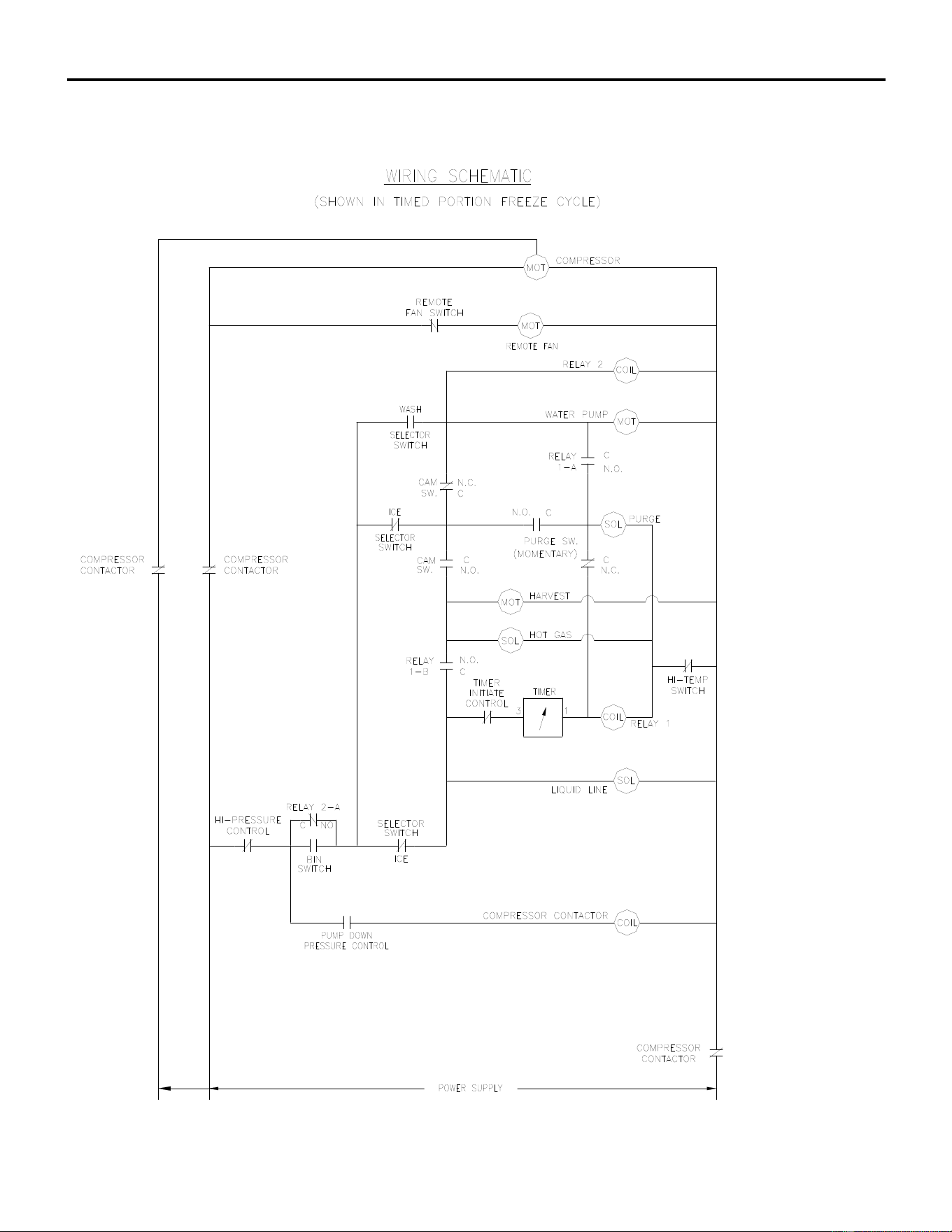
ICE Series Wiring Diagram
Page G22
ICE1007 Remote Wiring Schematic
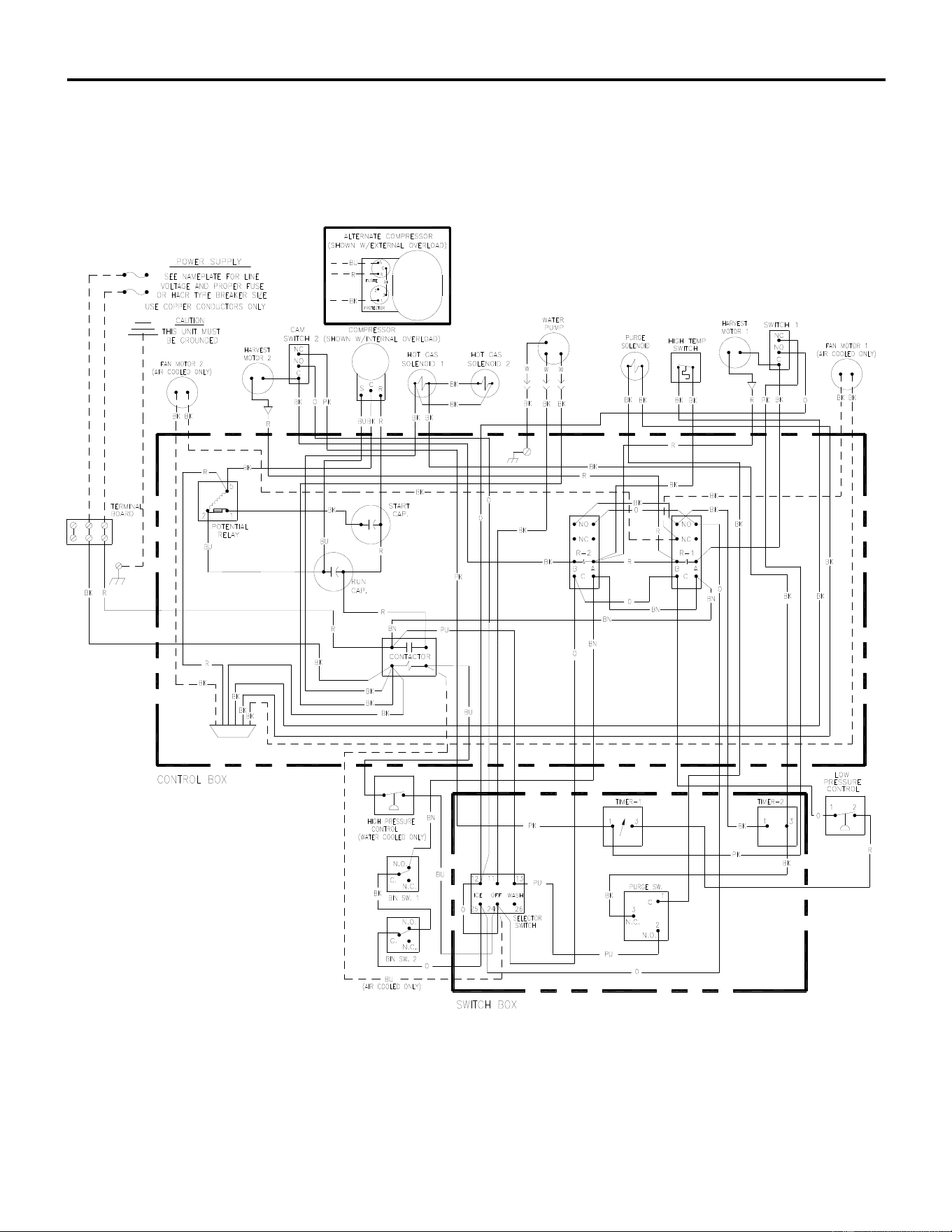
ICE Series Wiring Diagram
Page G23
ICE1405/1406/1806/2005/2106 Air and Water Wiring Diagram
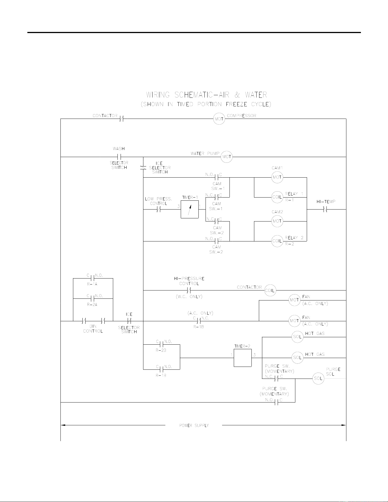
ICE Series Wiring Diagram
Page G24
ICE1405/1406/1806/2005/2106 Air and Water Wiring Schematic

ICE Series Wiring Diagram
Page G25
ICE1405/1406/1806/2005/2106 Remote Wiring Diagram
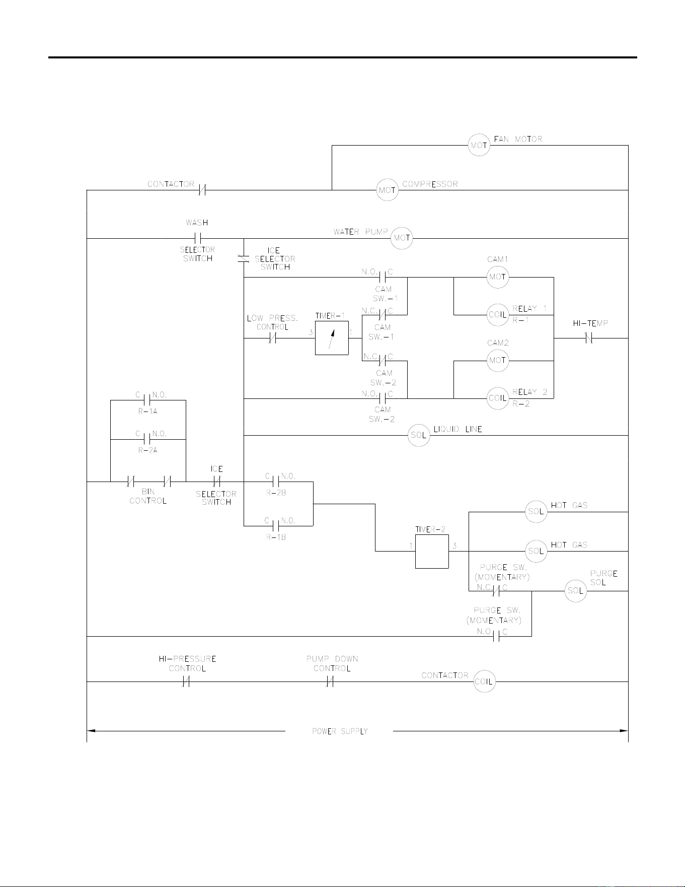
ICE Series Wiring Diagram
Page G26
ICE1405/1406/1806/2005/2106 Remote Wiring Schematic
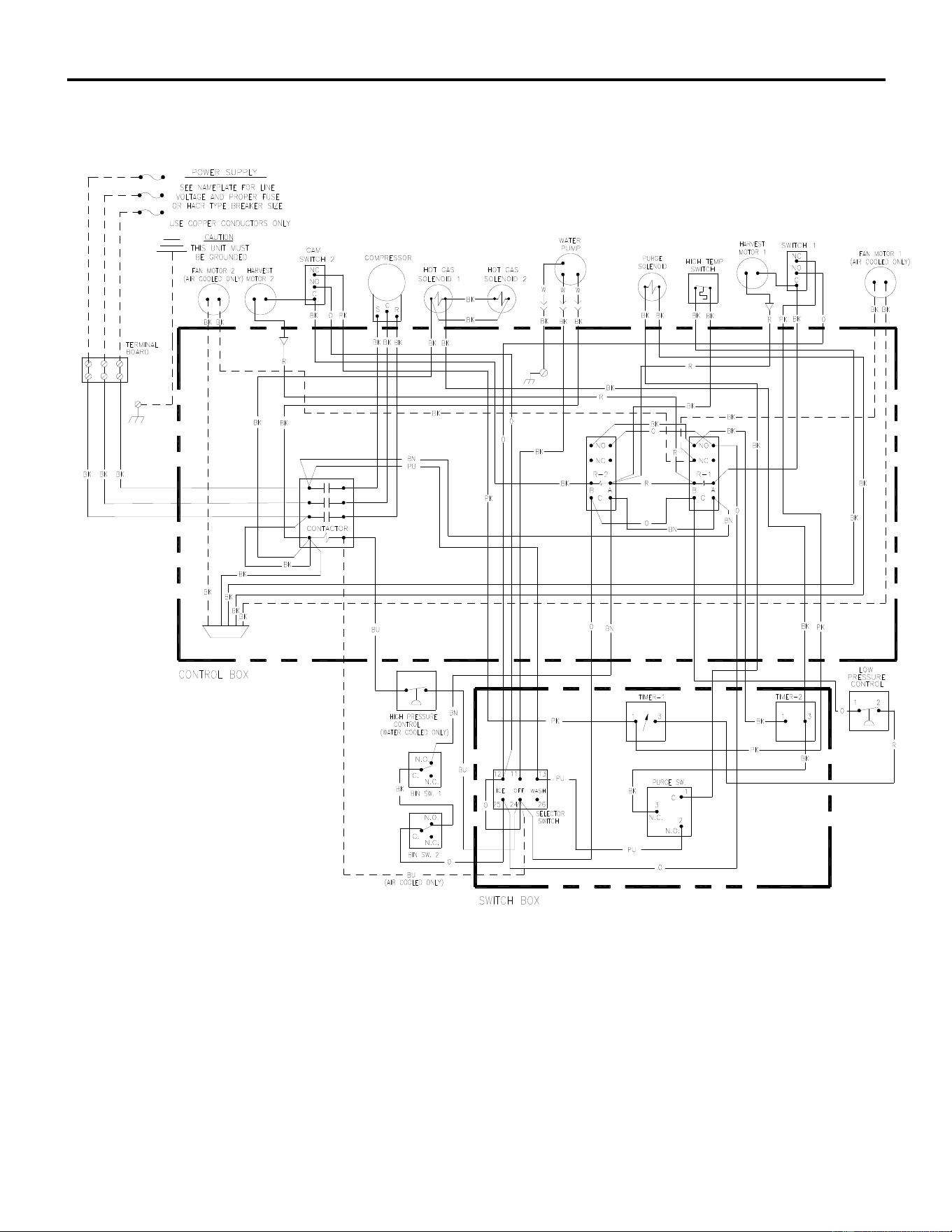
ICE Series Wiring Diagram
Page G27
ICE1407/1807/2107 Air and Water Wiring Diagram
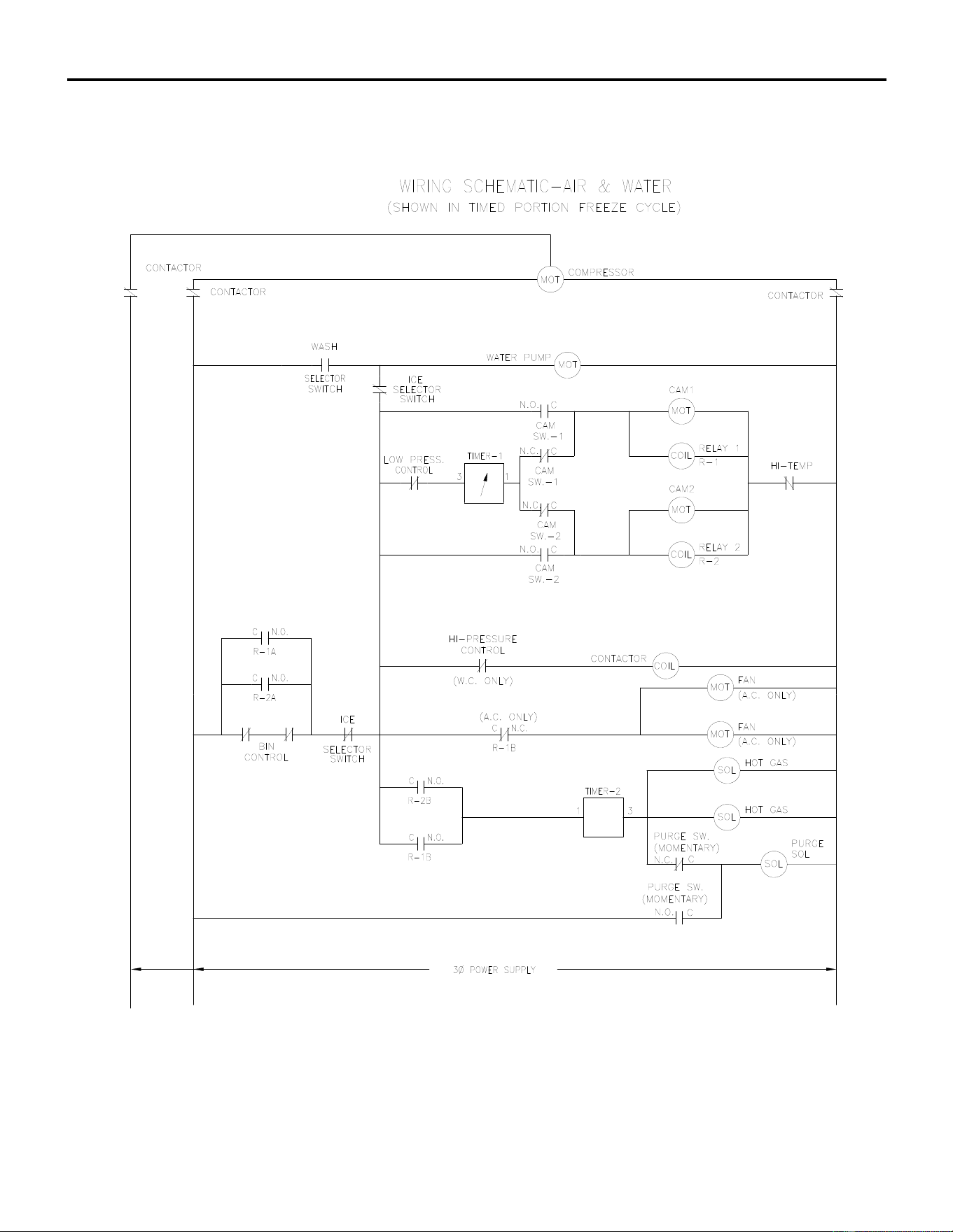
ICE Series Wiring Diagram
Page G28
ICE1407/1807/2107 Air and Water Wiring Schematic
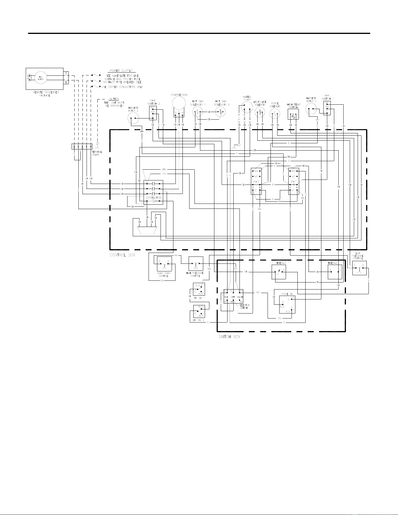
ICE Series Wiring Diagram
Page G29
ICE1407/1807/2107 Remote Wiring Diagram
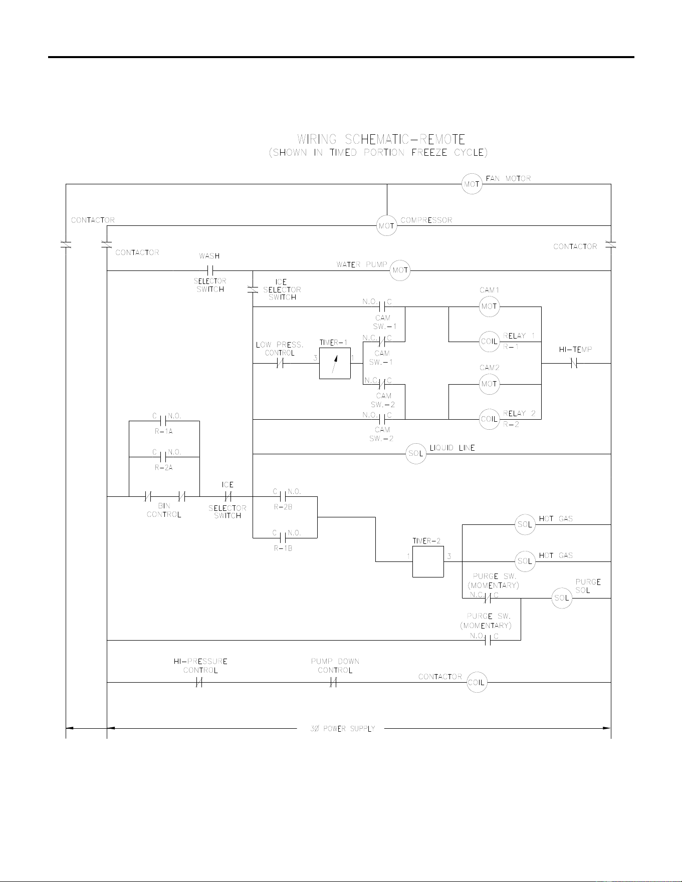
ICE Series Wiring Diagram
Page G30
ICE1407/1807/2107 Remote Wiring Schematic
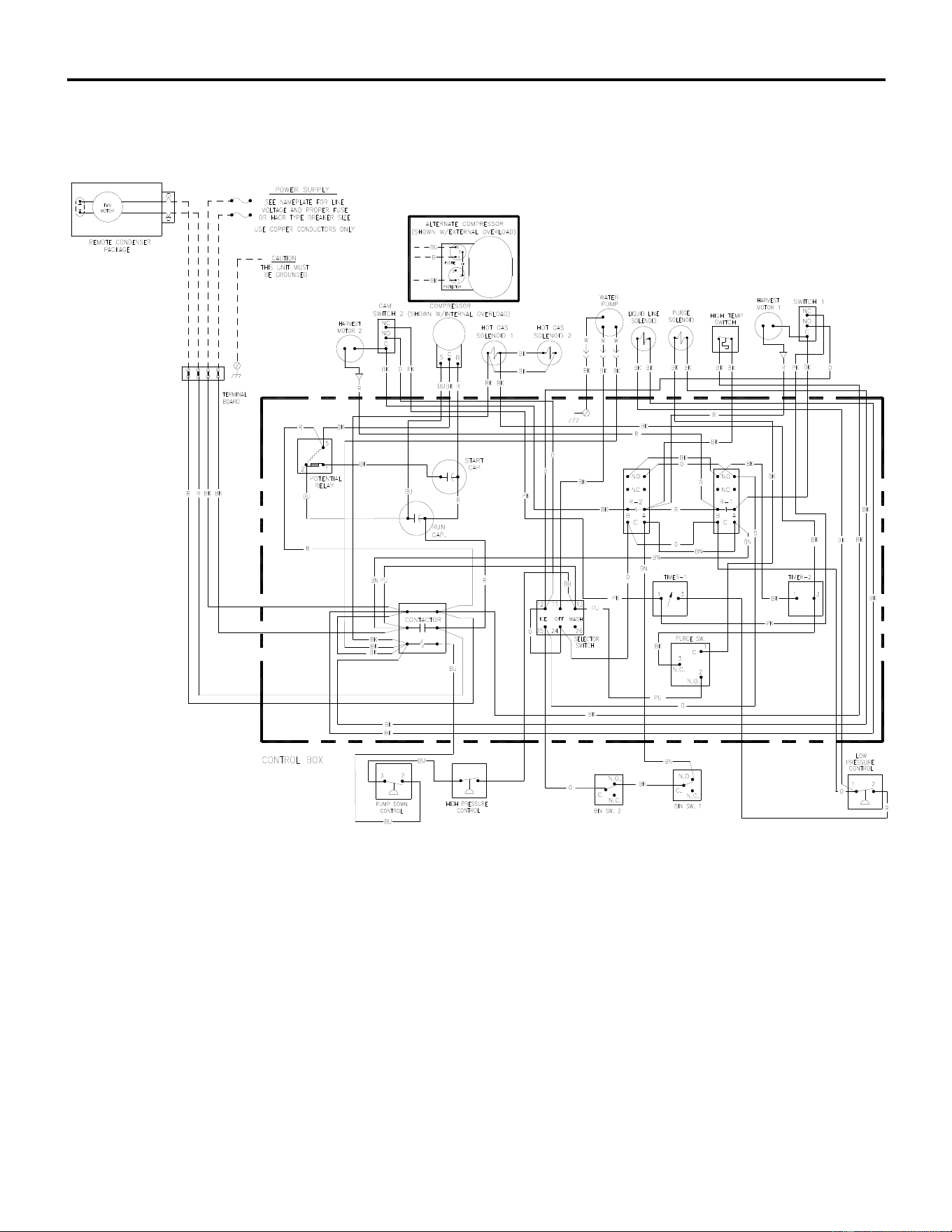
ICE Series Wiring Diagram
Page G31
ICE1606 Remote Wiring Diagram
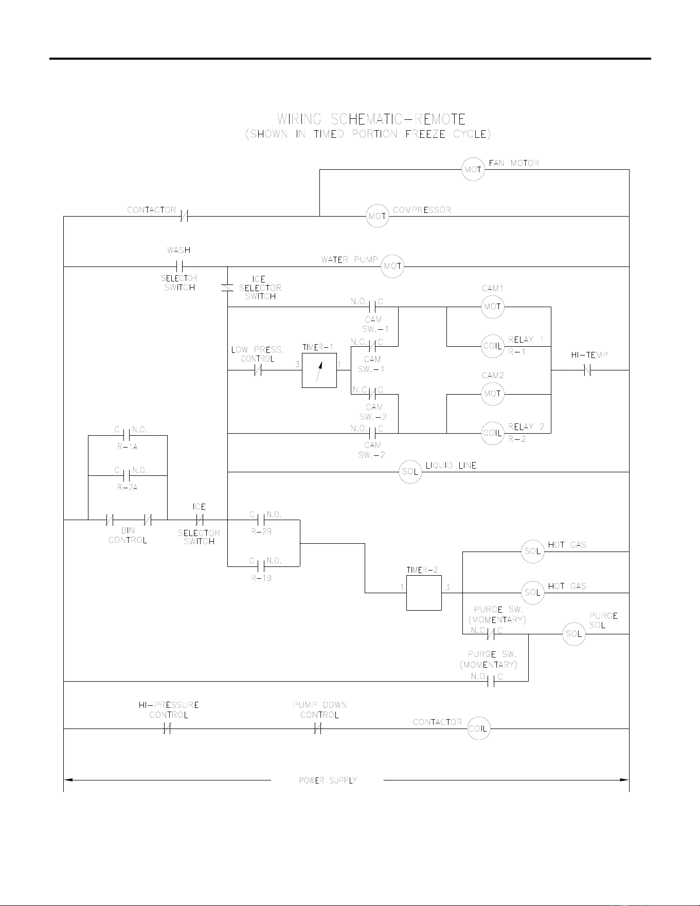
ICE Series Wiring Diagram
Page G32
ICE1606 Remote Wiring Schematic
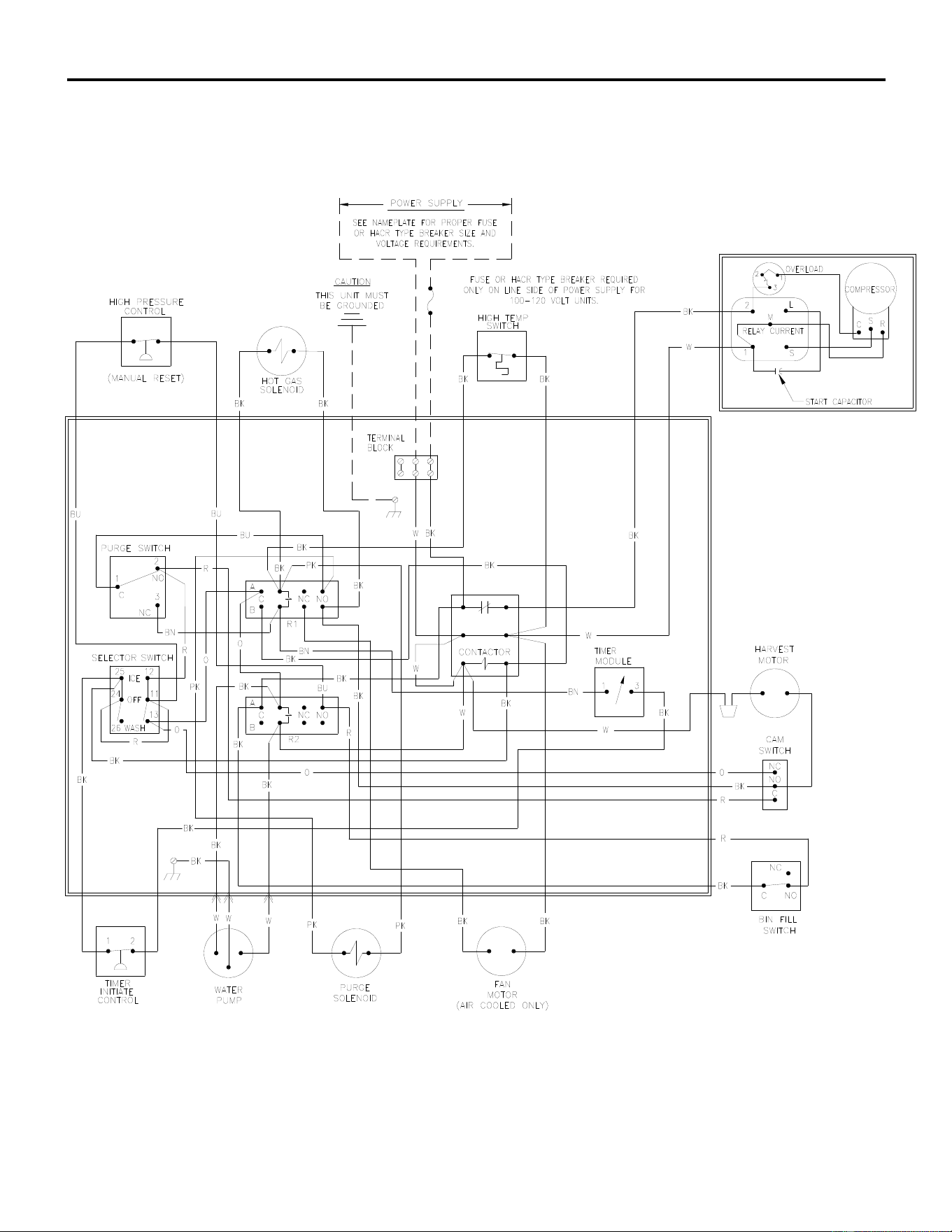
ICE Series Wiring Diagram
Page G33
ICE0320 Air and Water Wiring Diagram
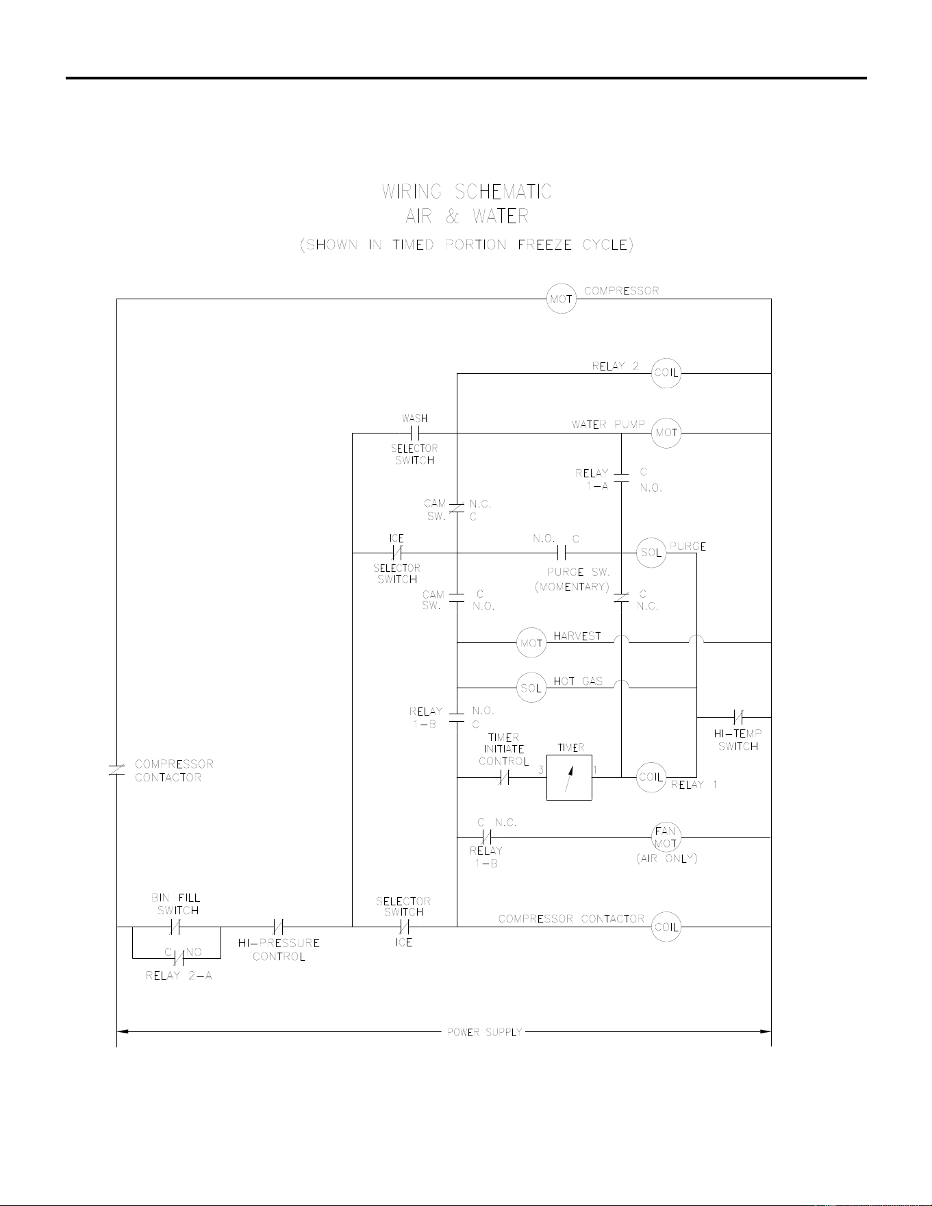
ICE Series Wiring Diagram
Page G34
ICE0320 Air and Water Wiring Schematic
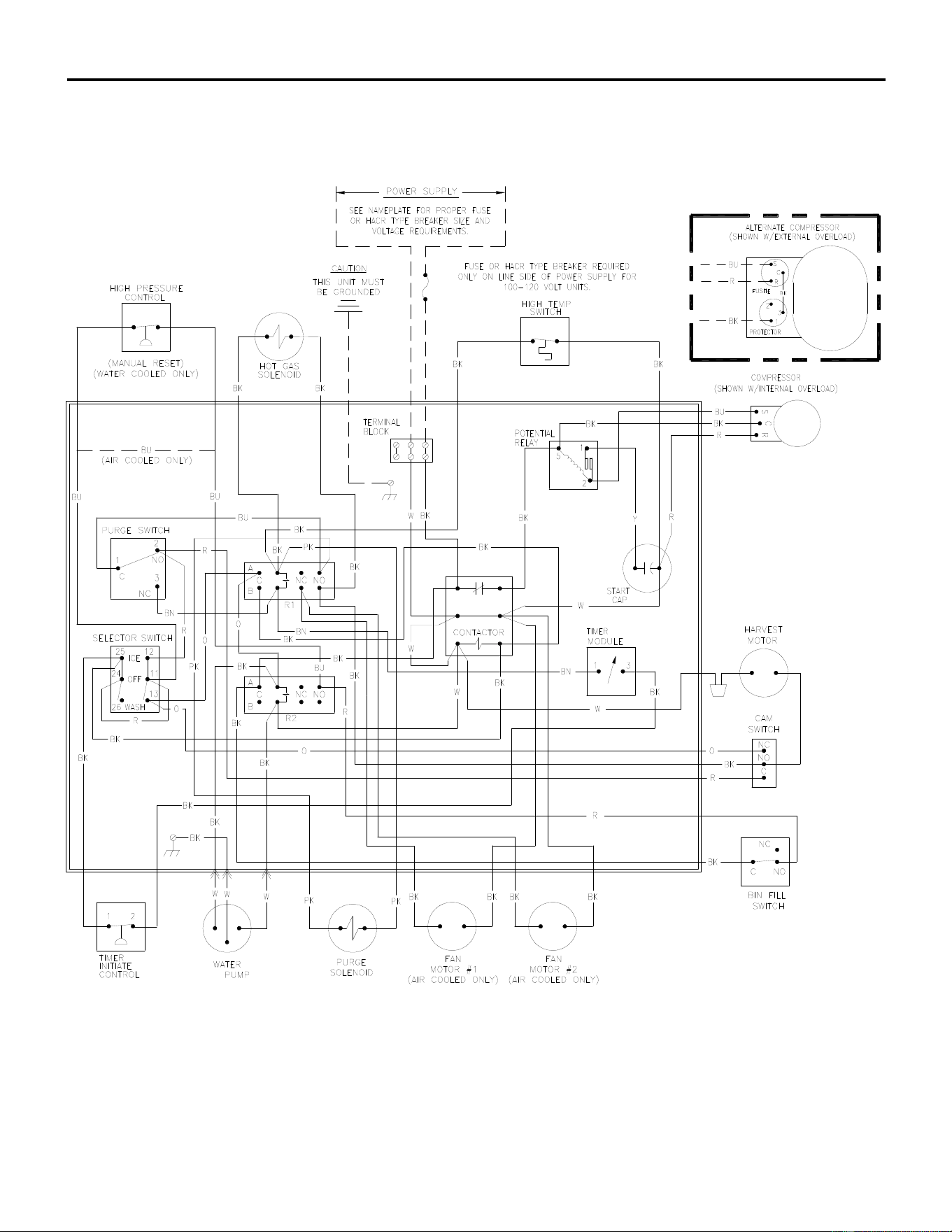
ICE Series Wiring Diagram
Page G35
ICE0520 Air and Water Wiring Diagram
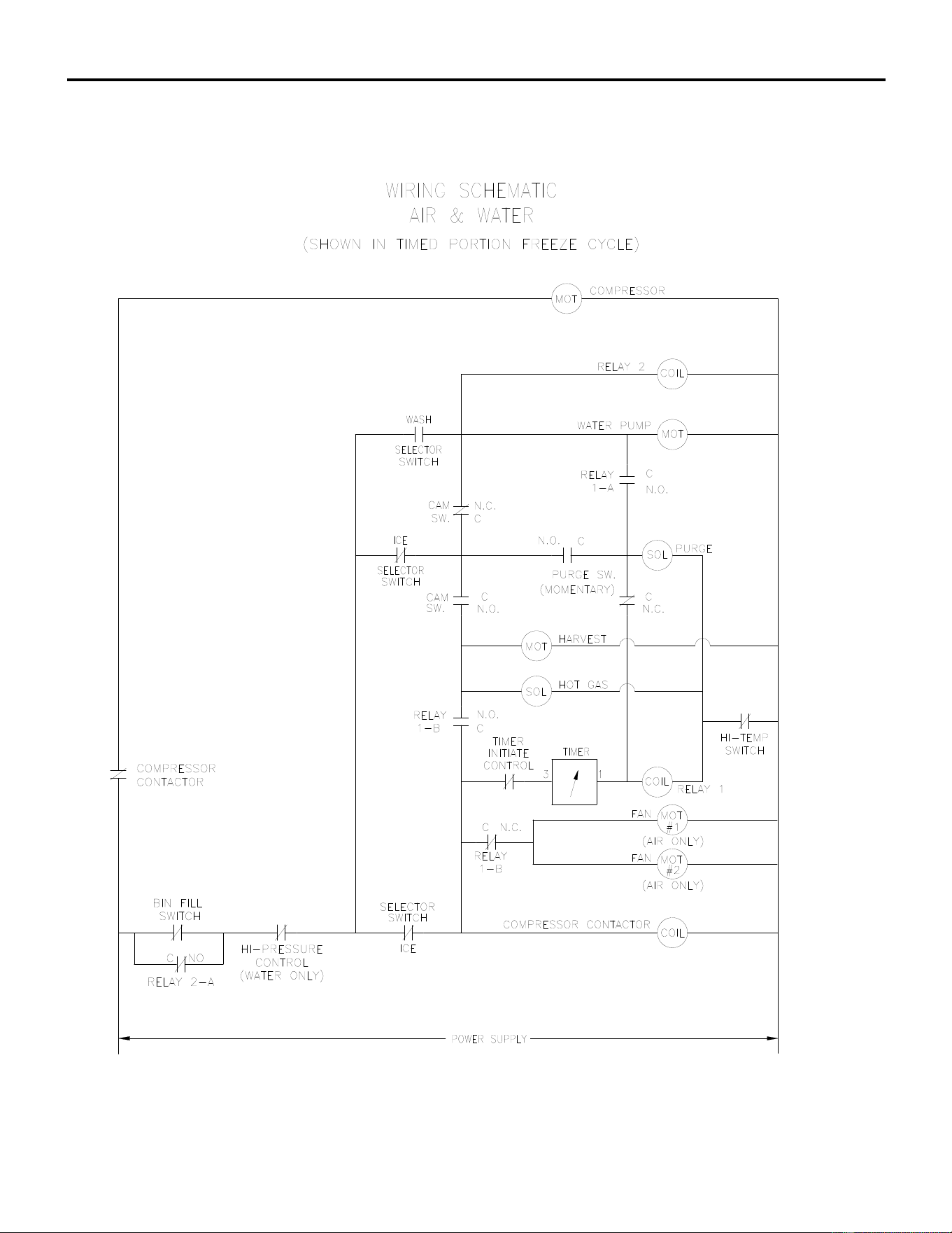
ICE Series Wiring Diagram
Page G36
ICE0520 Air and Water Wiring Schematic
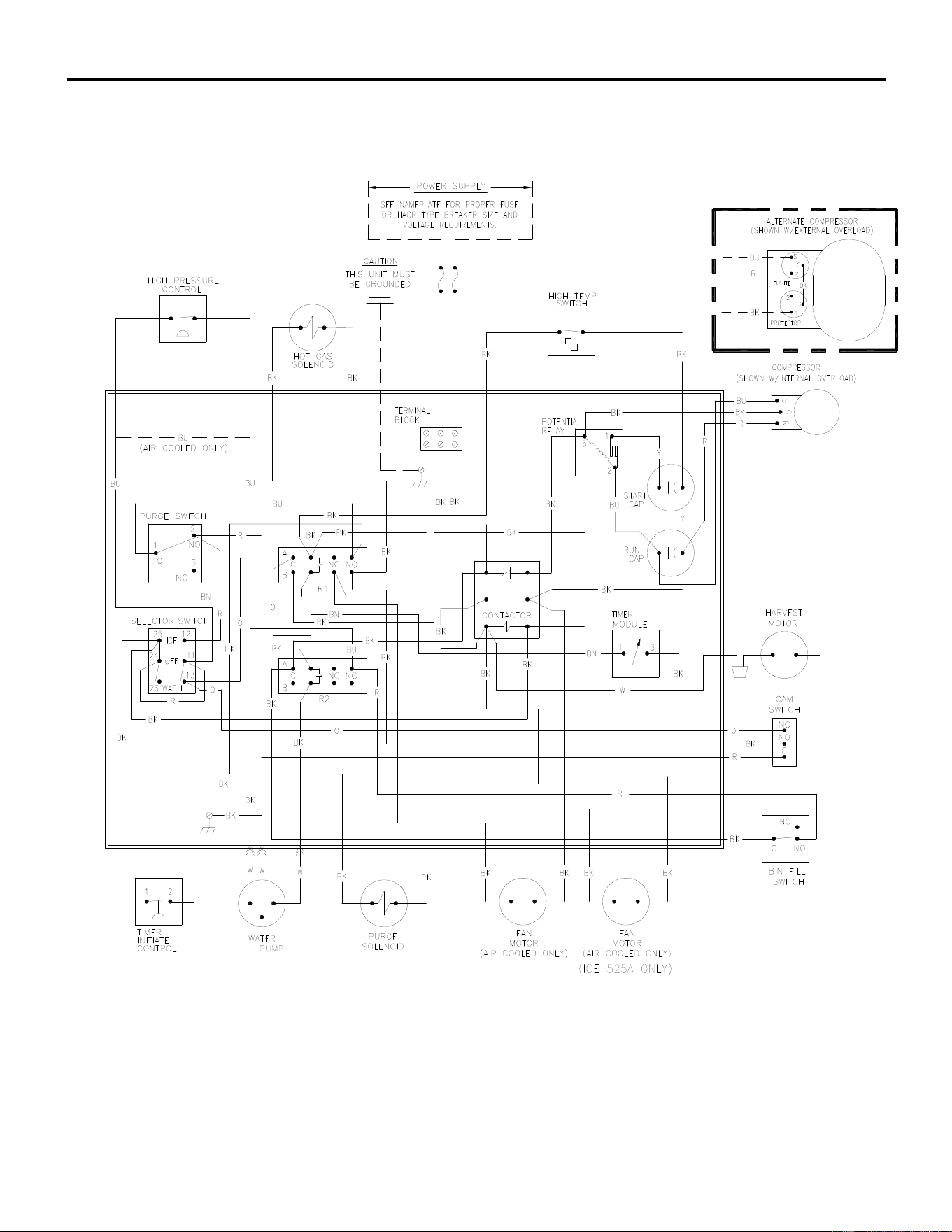
ICE Series Wiring Diagram
Page G37
ICE0325/0525 Air and Water Wiring Diagram
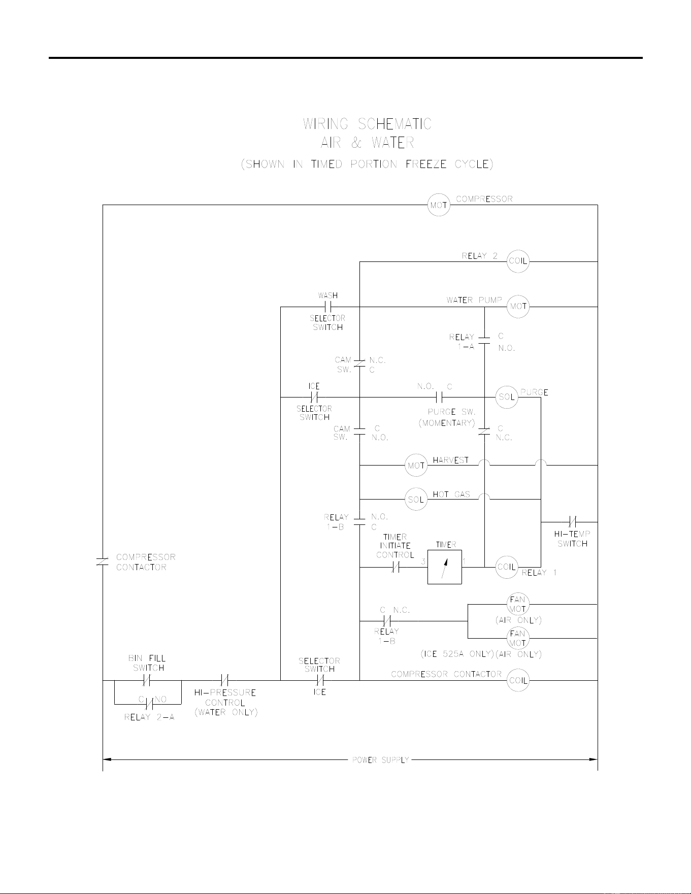
ICE Series Wiring Diagram
Page G38
ICE0325/0525 Air and Water Wiring Schematic
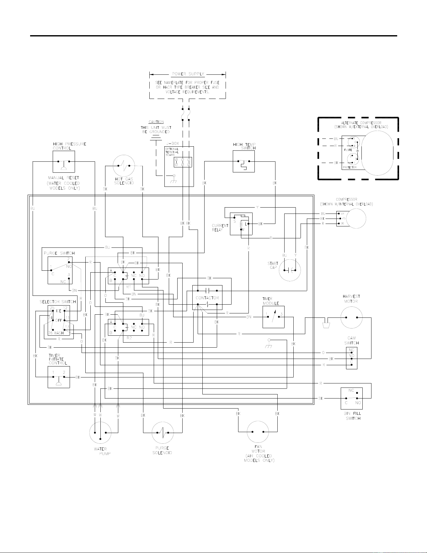
ICE Series Wiring Diagram
Page G39
ICE0305 Air and Water Wiring Diagram
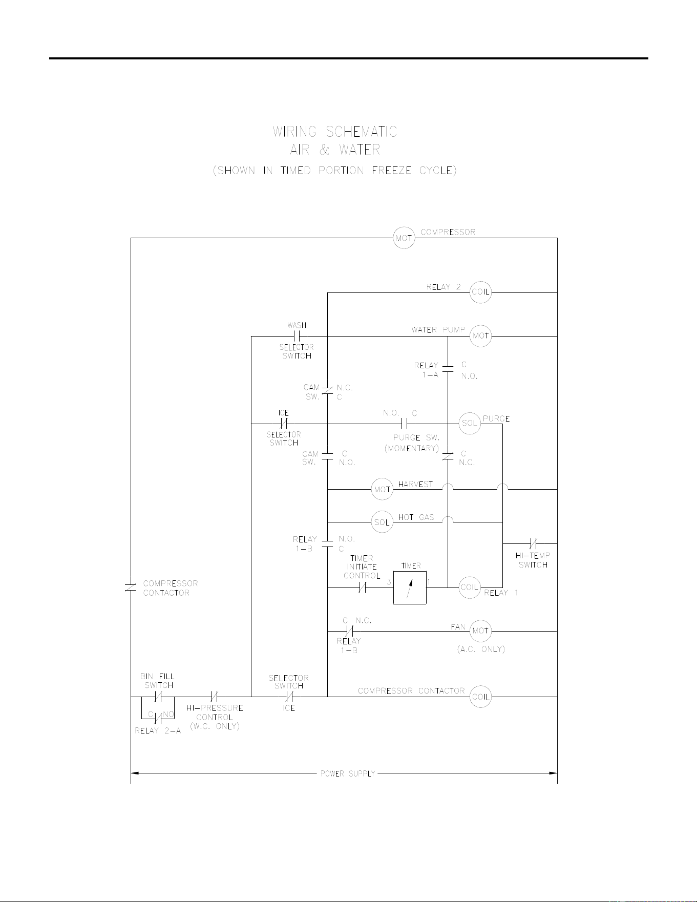
ICE Series Wiring Diagram
Page G40
ICE0305 Air and Water Wiring Schematic
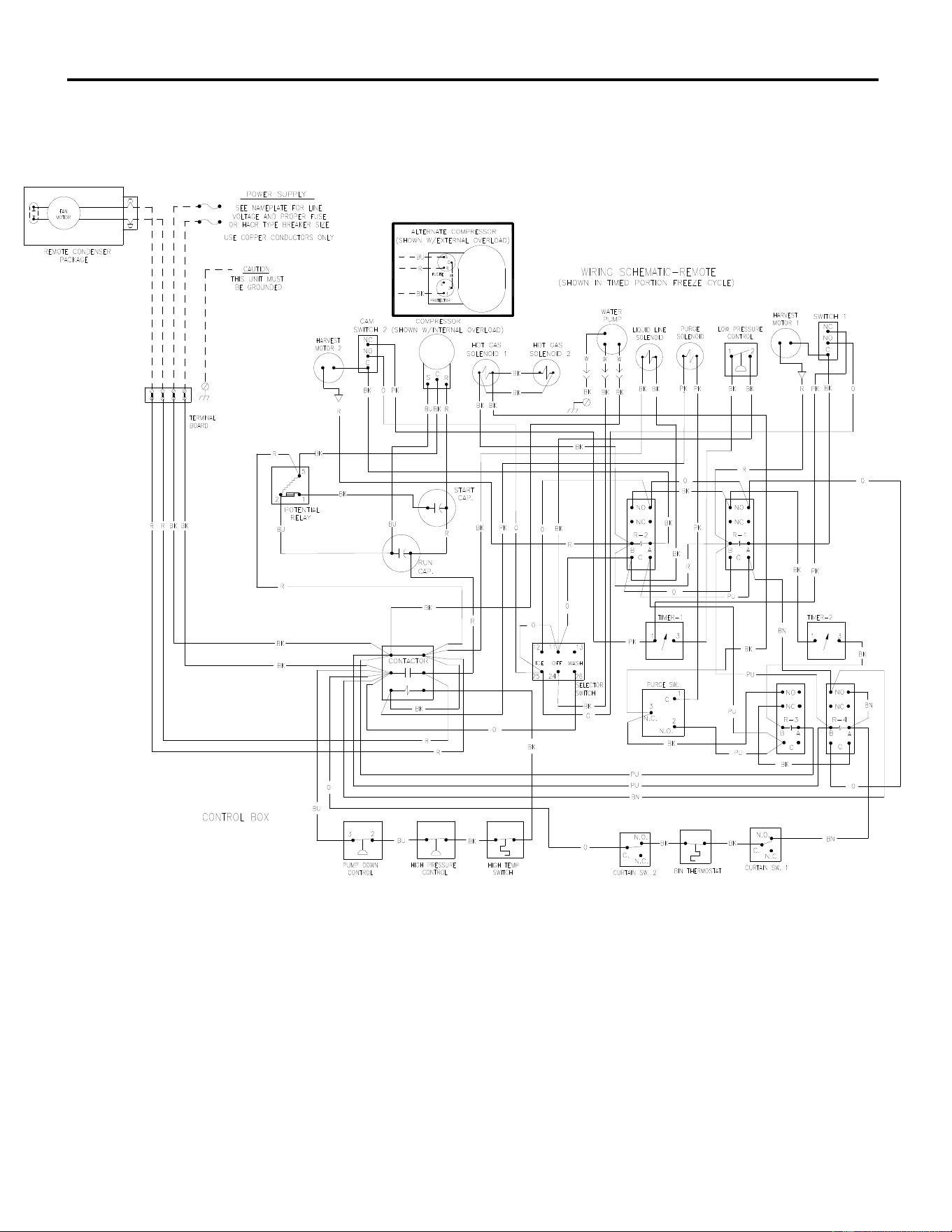
ICE Series Wiring Diagram
Page G41
ICE1506 Remote
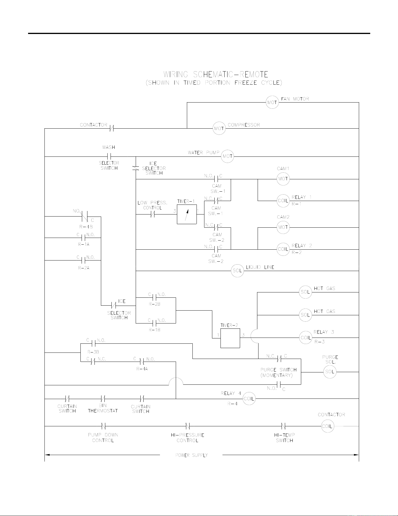
ICE Series Wiring Diagram
Page G42
ICE1506 Remote
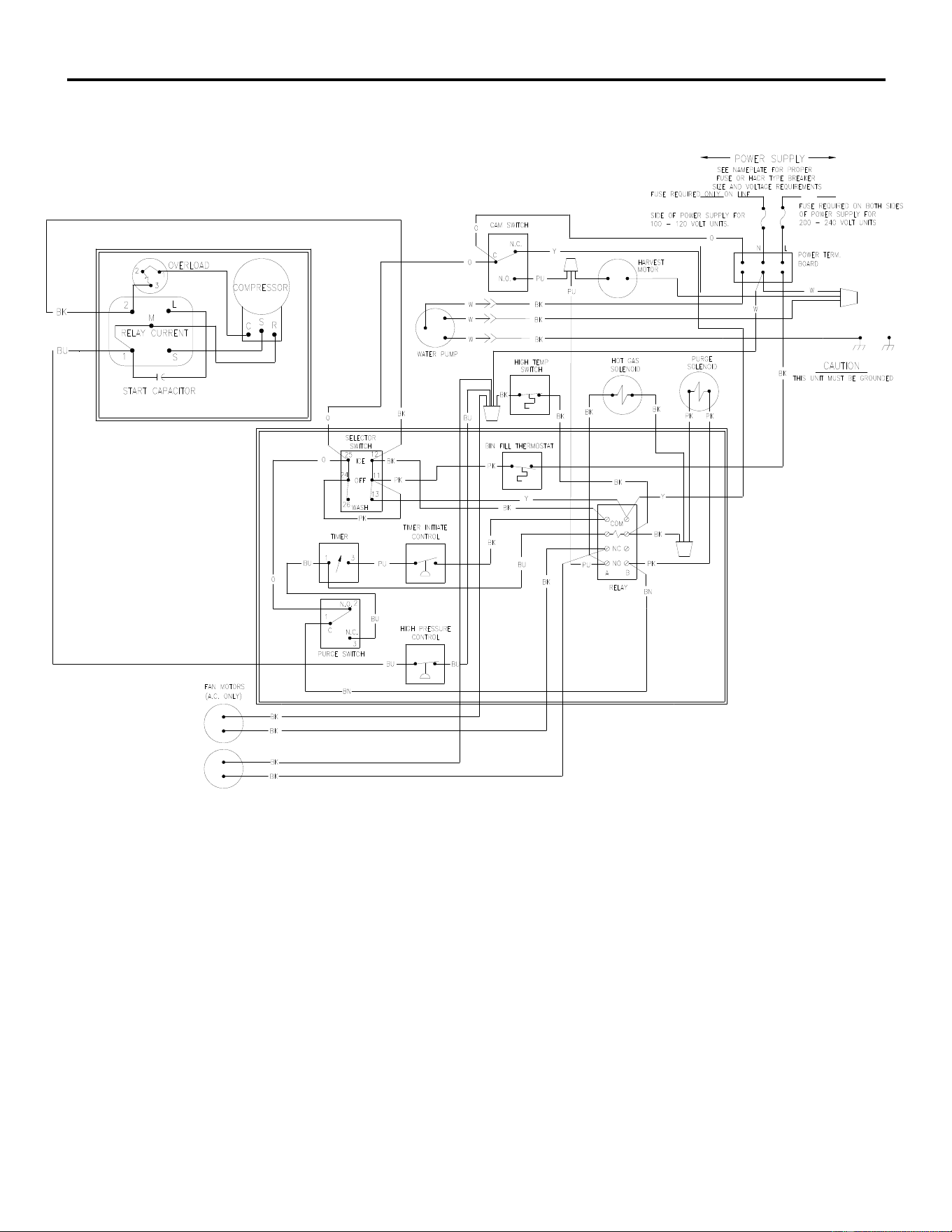
ICE Series Wiring Diagram
Page G43
ICEU300 Air and Water
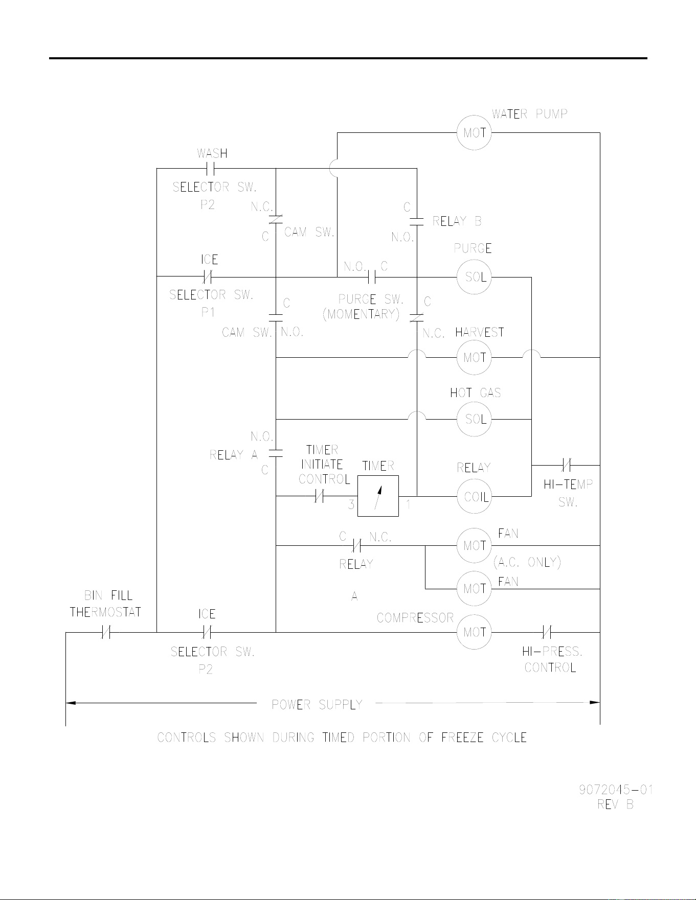
ICE Series Wiring Diagram
ICEU300 Air and Water
Page G44
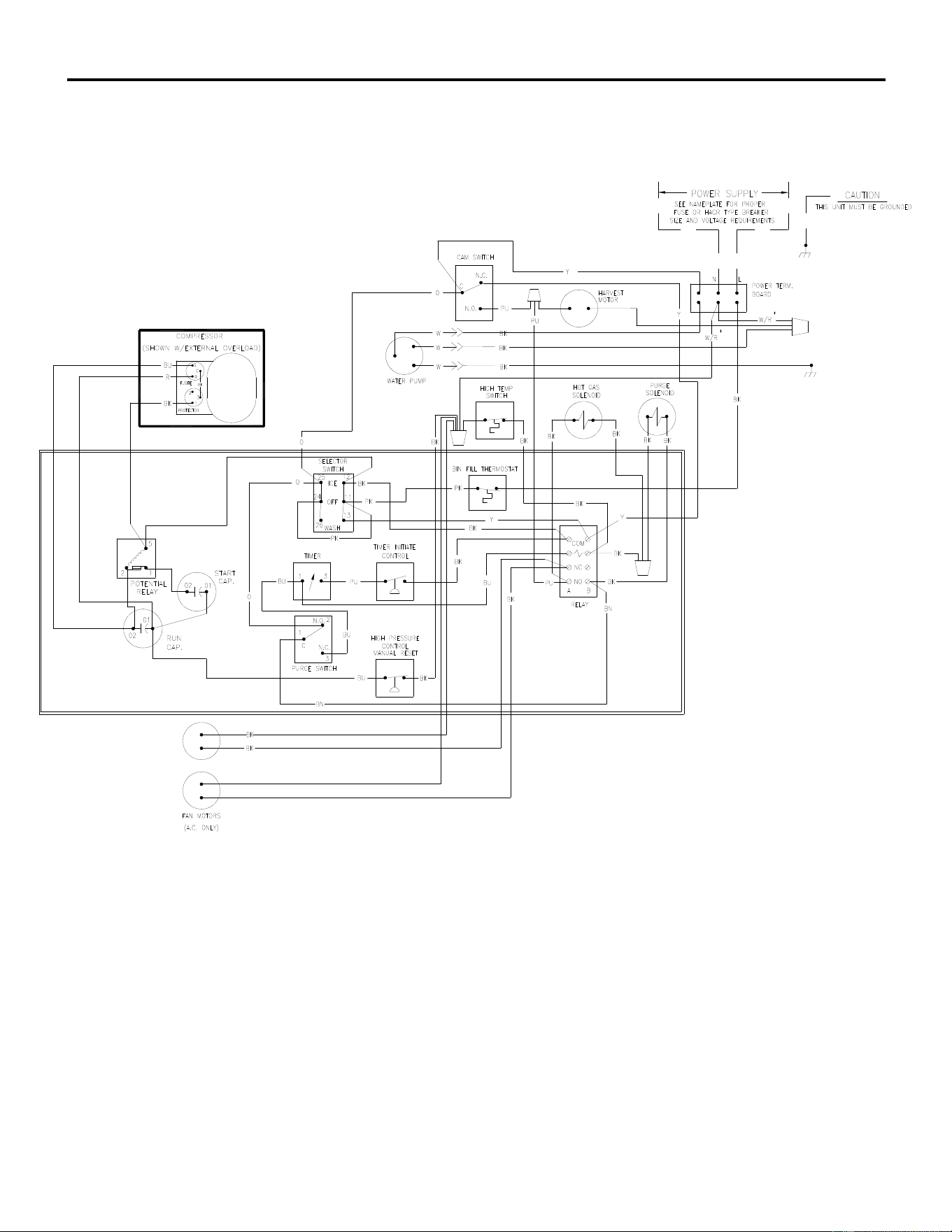
ICE Series Wiring Diagram
Page G45
ICEU305 Air and Water
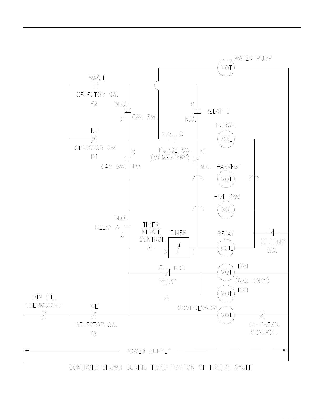
ICE Series Wiring Diagram
Page G46
ICEU305 Air and Water
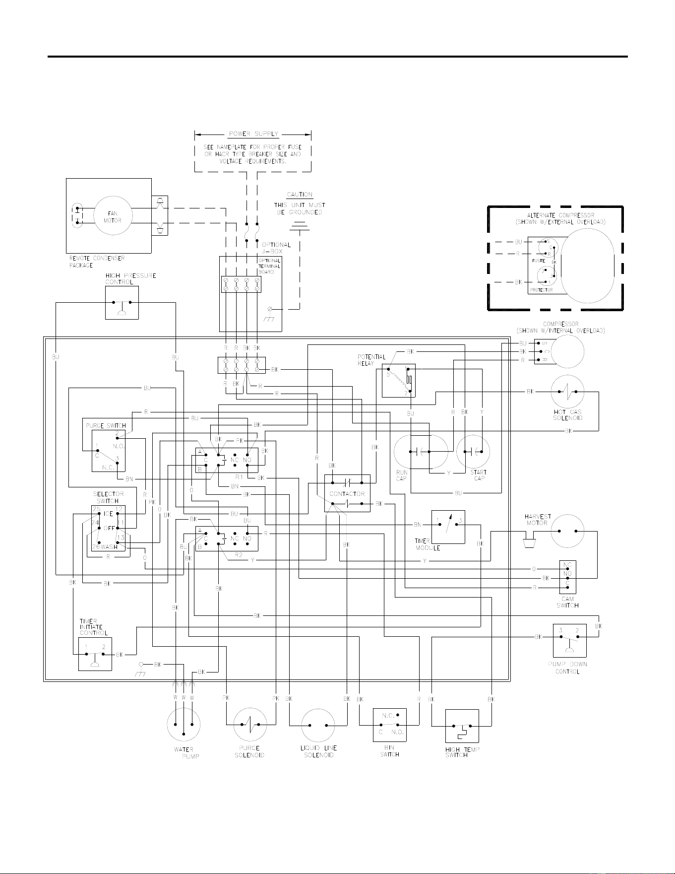
ICE Series Wiring Diagram
Page G47
ICE0500 Remote Wiring Diagram (R3)
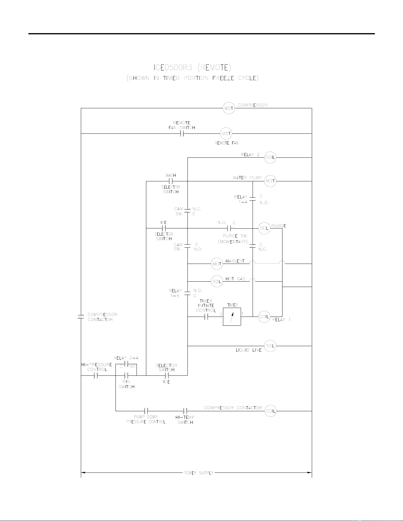
ICE Series Wiring Diagram
Page G48
ICE0500 Remote Wiring Schematic (R3)
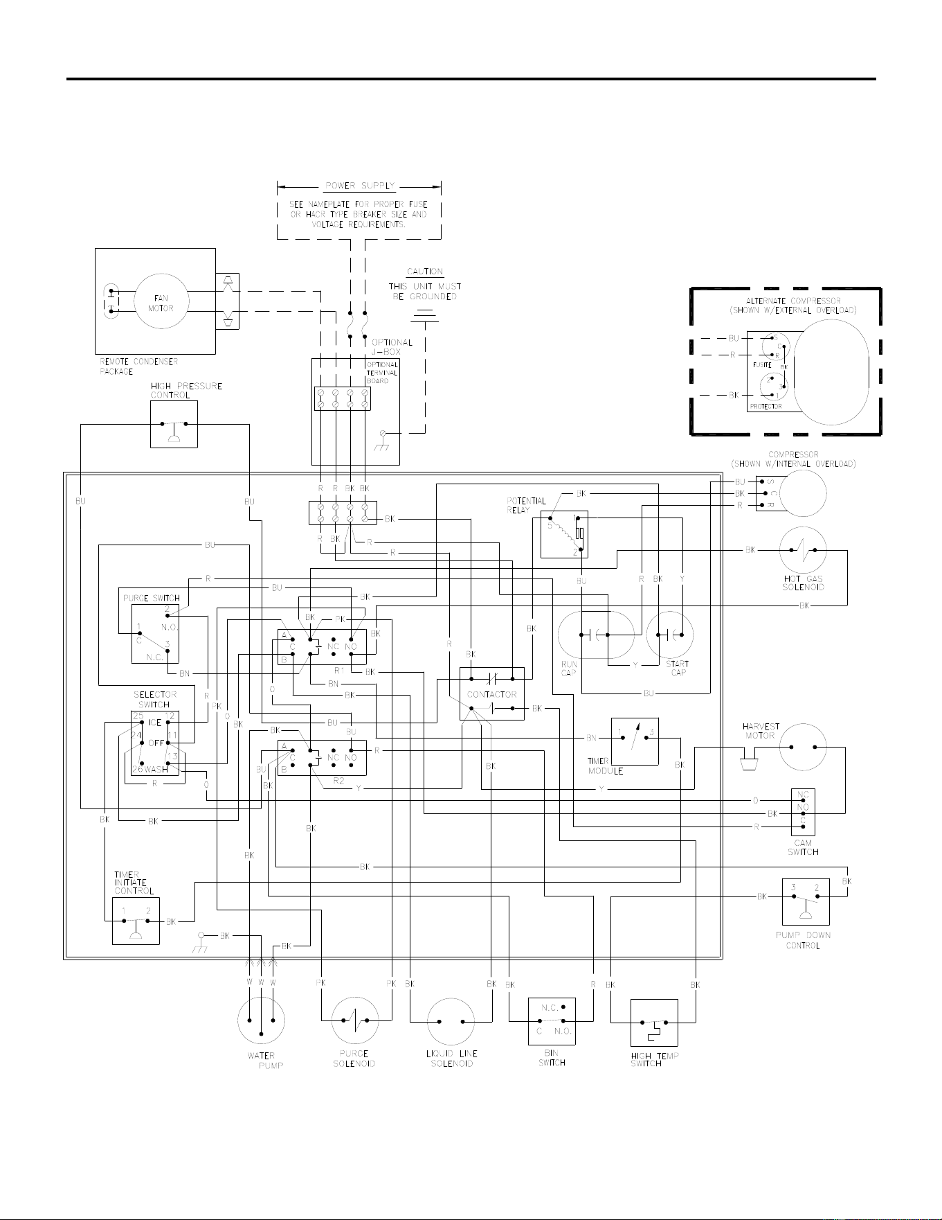
ICE Series Wiring Diagram
ICE0605/0606/0806/1006 Remote Wiring Diagram (R3)
Page G49
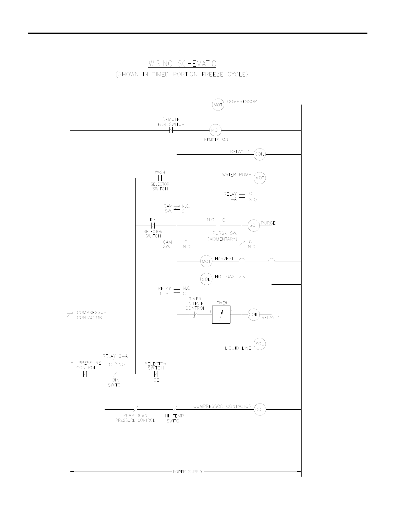
ICE Series Wiring Diagram
Page G50
ICE0605/0606/0806/1006 Remote Wiring Schematic (R3)
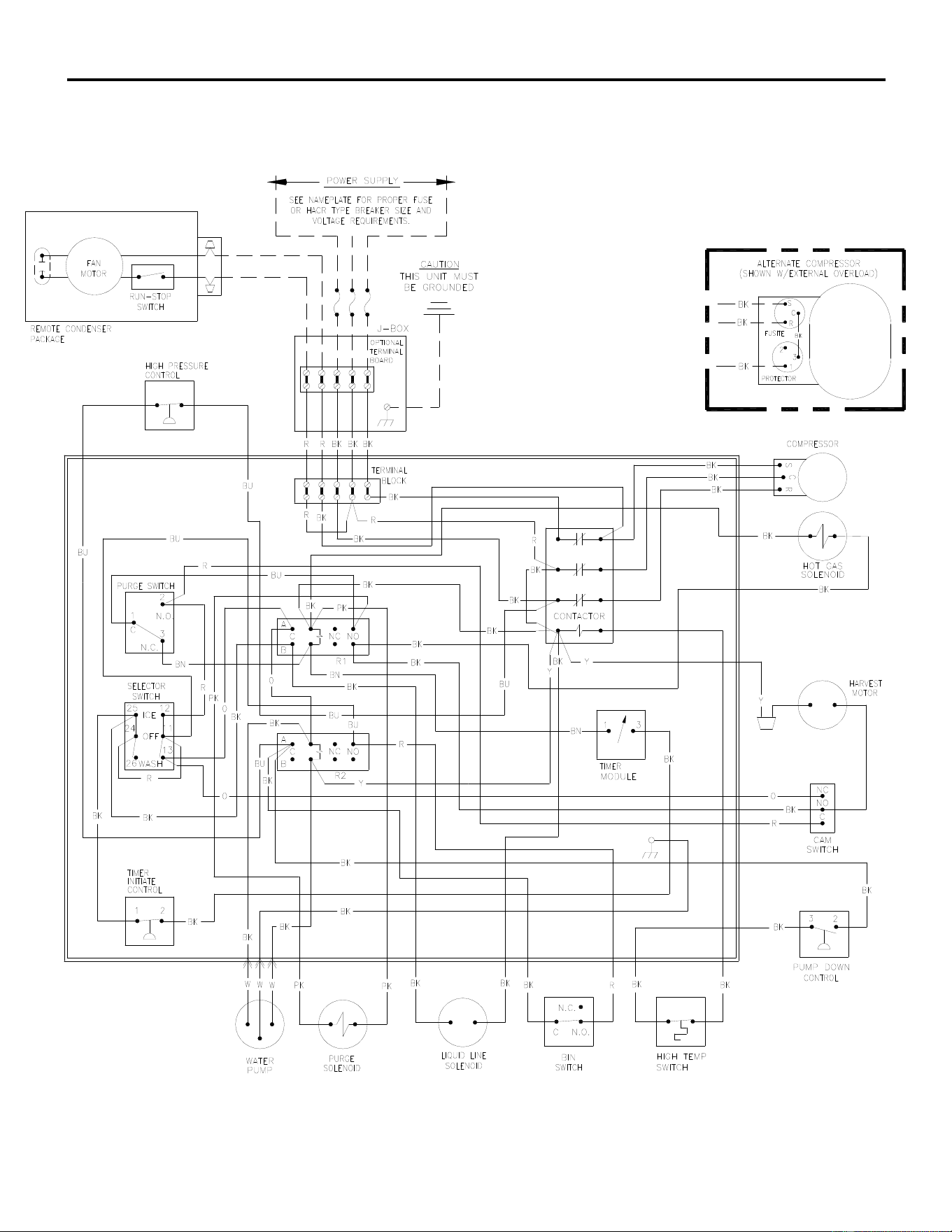
ICE Series Wiring Diagram
Page G51
ICE1007 Remote Wiring Diagram (R3)
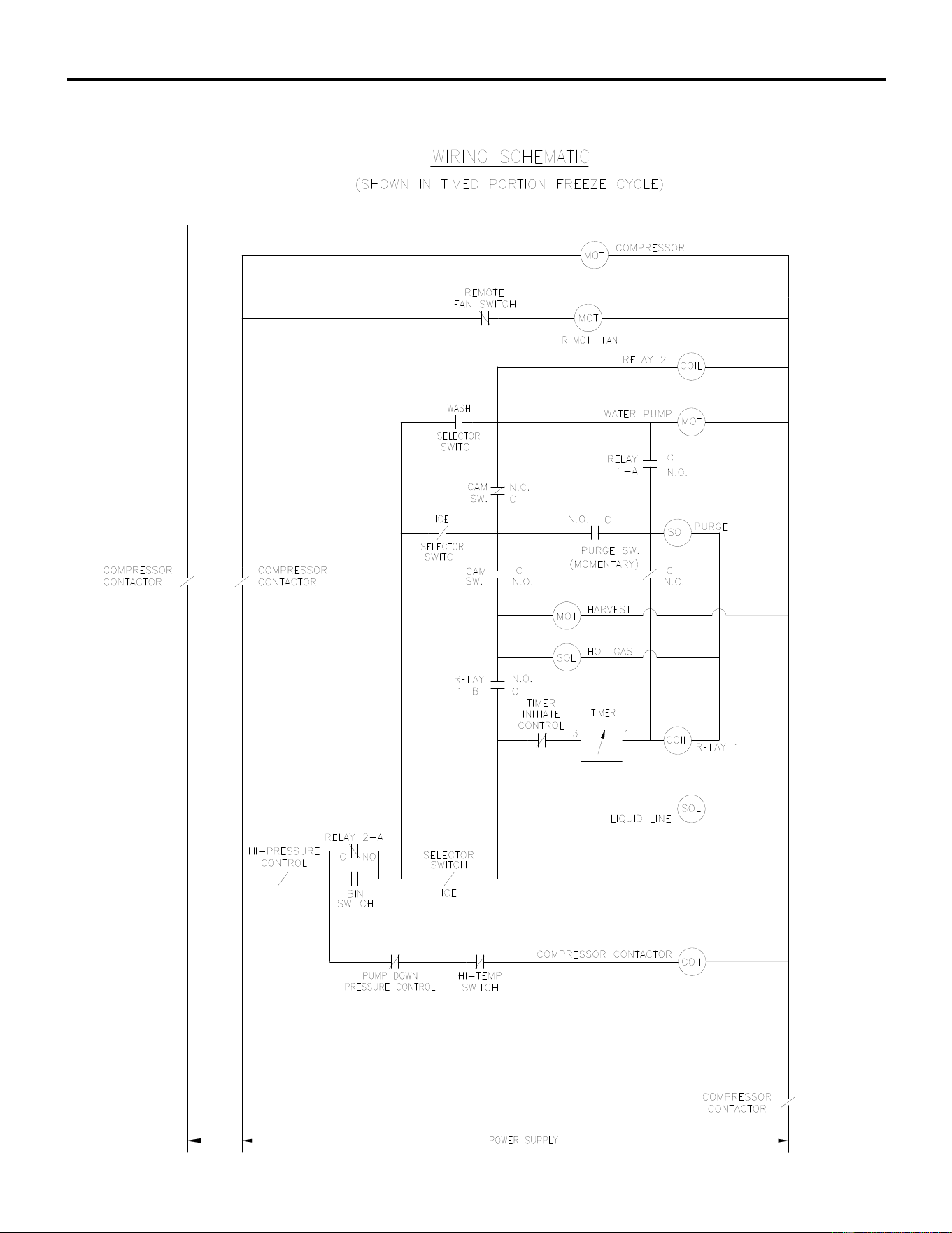
ICE Series Wiring Diagram
Page G52
ICE1007 Remote Wiring Schematic (R3)
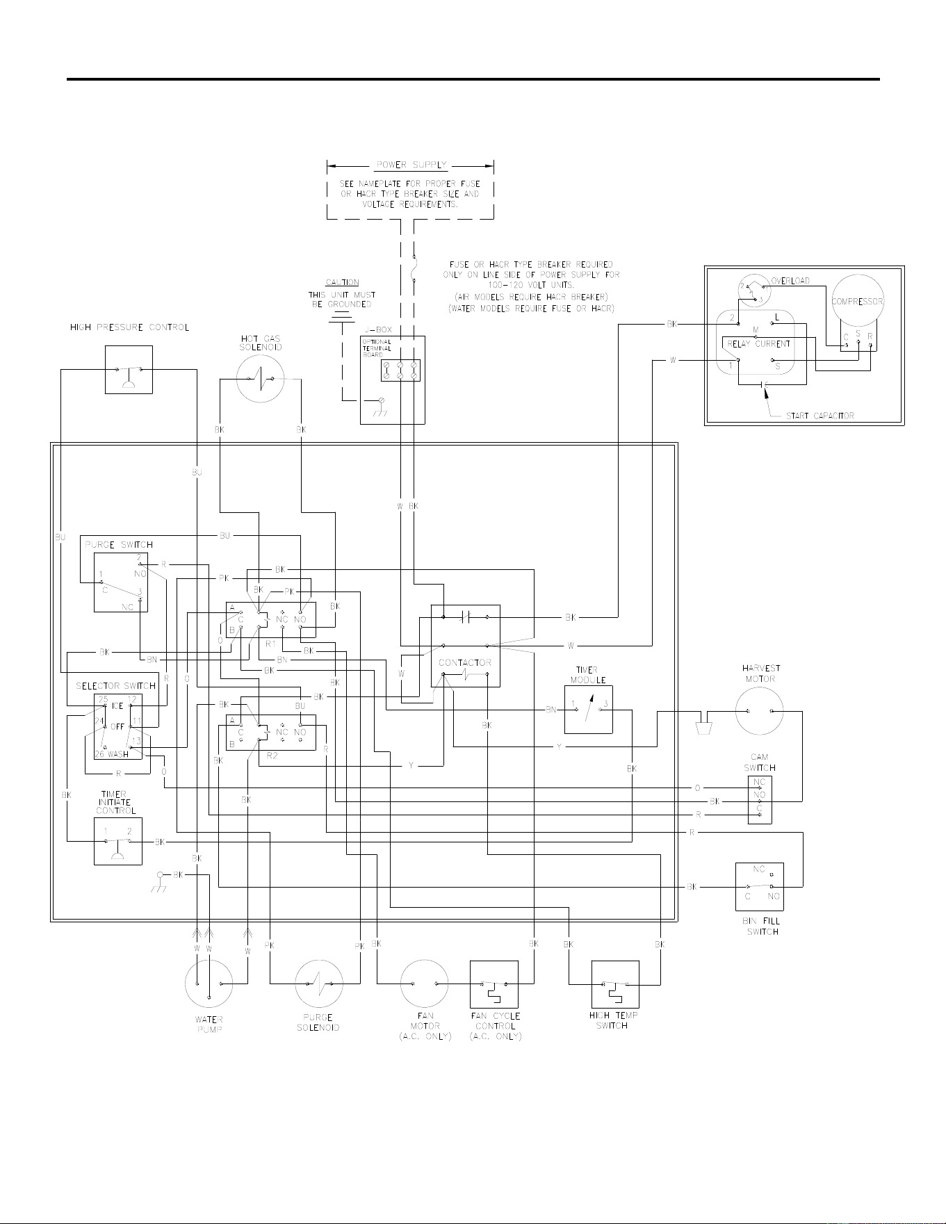
ICE Series Wiring Diagram
Page G53
ICE0250 Air4 and Water4, ICE0400 Air3 and Water3 Wiring Diagram
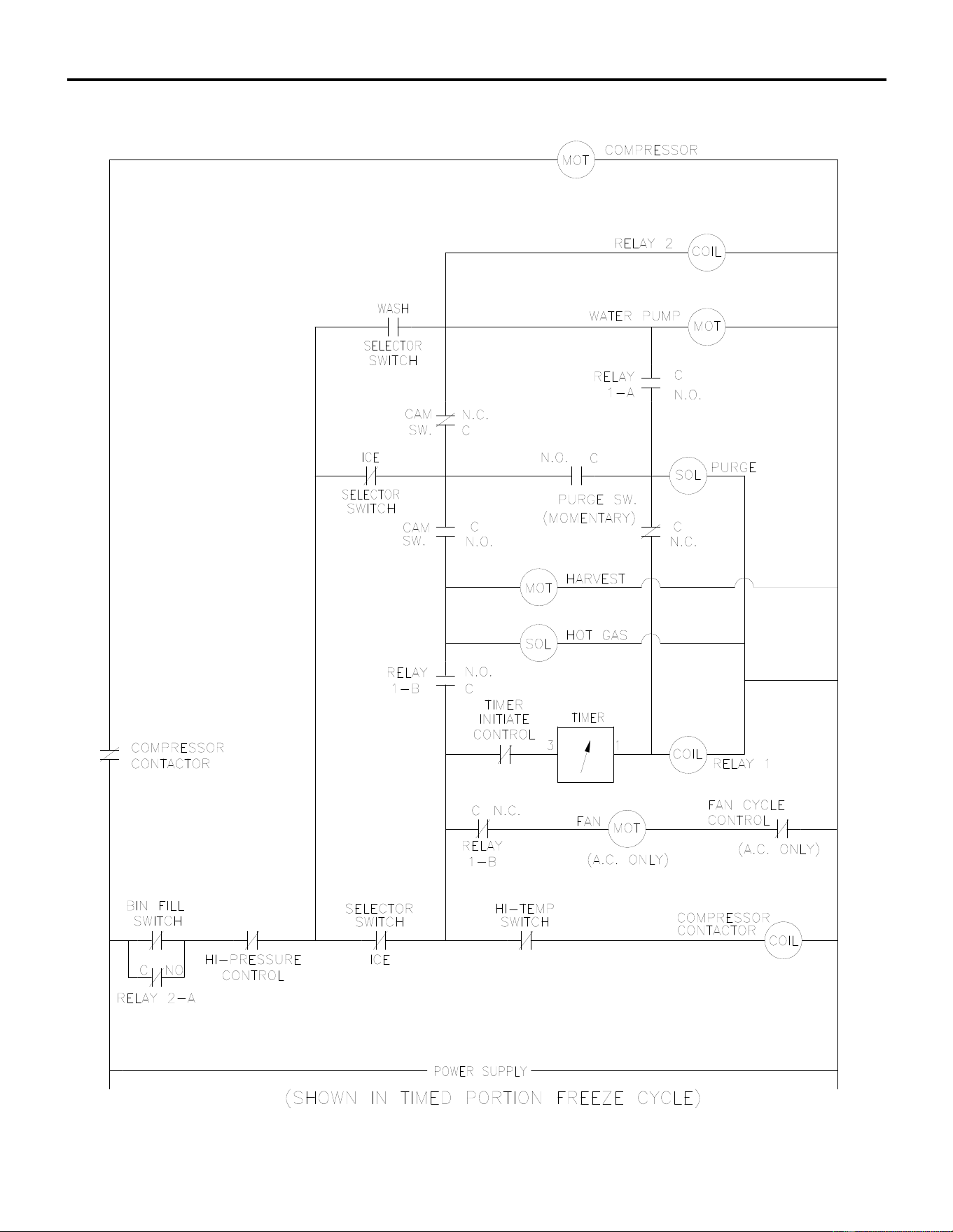
ICE Series Wiring Diagram
Page G54
ICE0250 Air4 and Water4, ICE0400 Air3 and Water3 Wiring Schematic
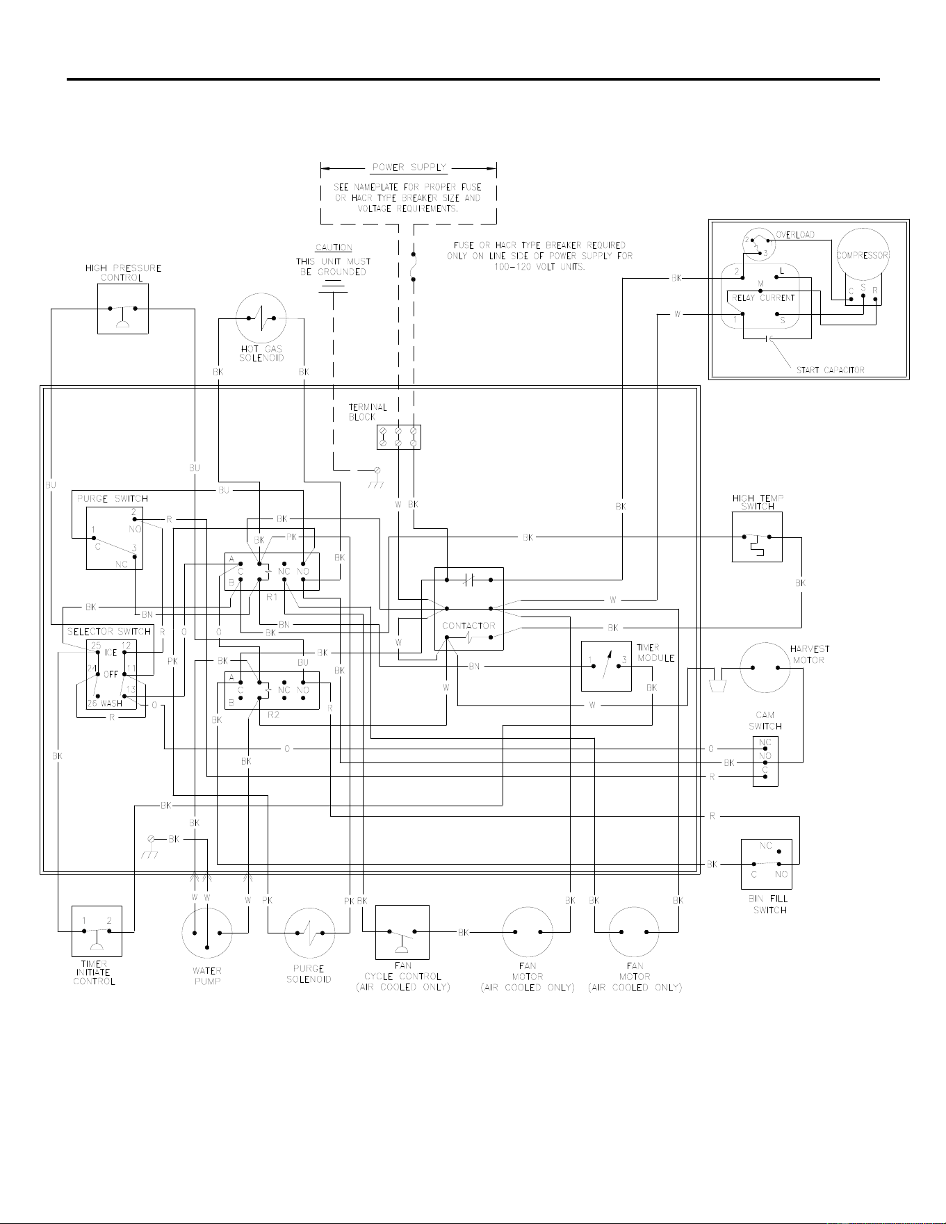
ICE Series Wiring Diagram
Page G55
ICE0320 Air3 and Water3, ICE0520 Air3 and Water3 Wiring Diagram
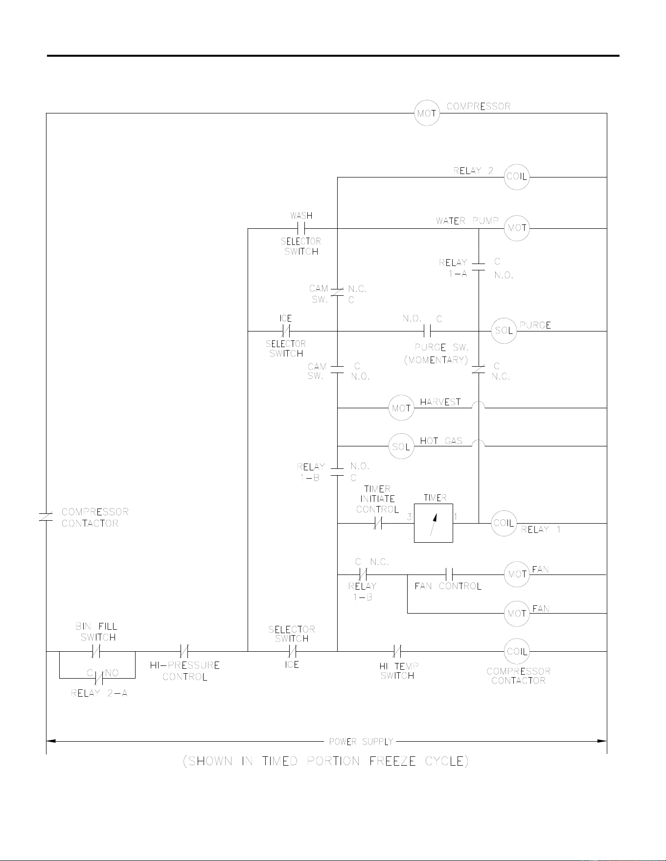
ICE Series Wiring Diagram
ICE0320 Air4 and Water4, ICE0520 Air3 and Water3 Wiring Schematic
Page G56
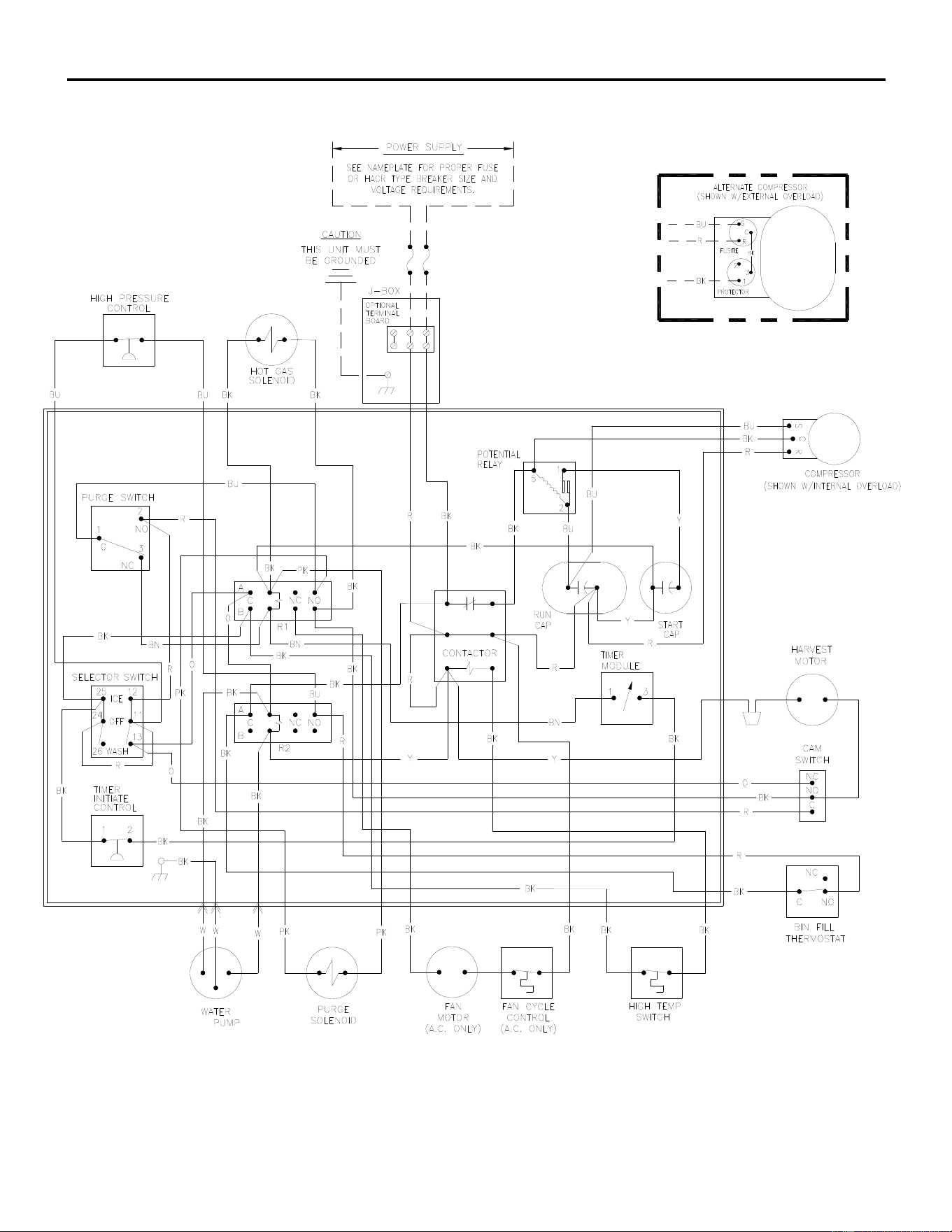
ICE Series Wiring Diagram
Page G57
ICE0406/405 Air3 and Water3, ICE0305 Air3 and Water3 Wiring Diagram
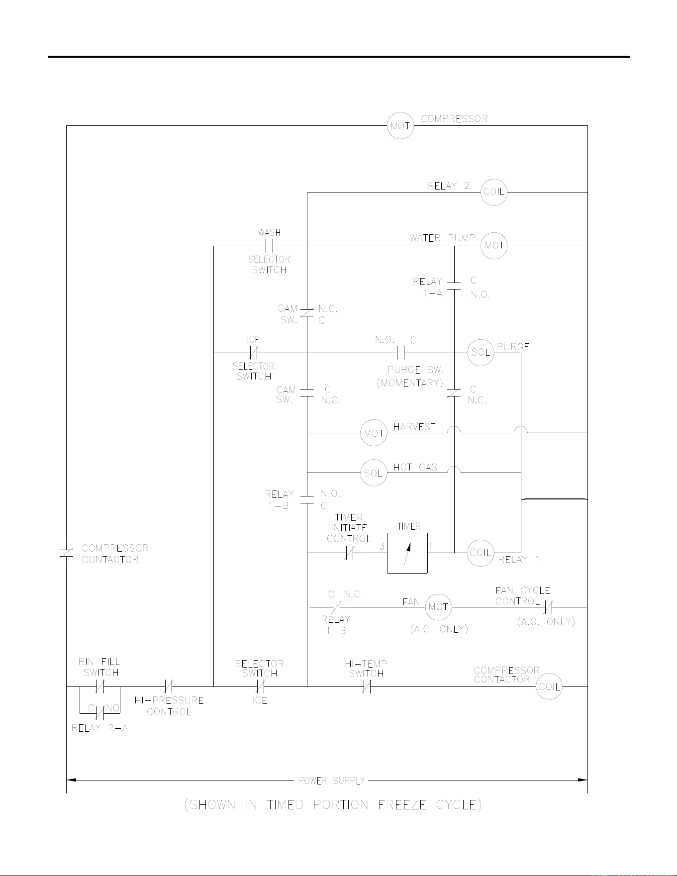
ICE Series Wiring Diagram
Page G58
ICE0406/405 Air3 and Water3, ICE0305 Air3 and Water3 Wiring Schematic
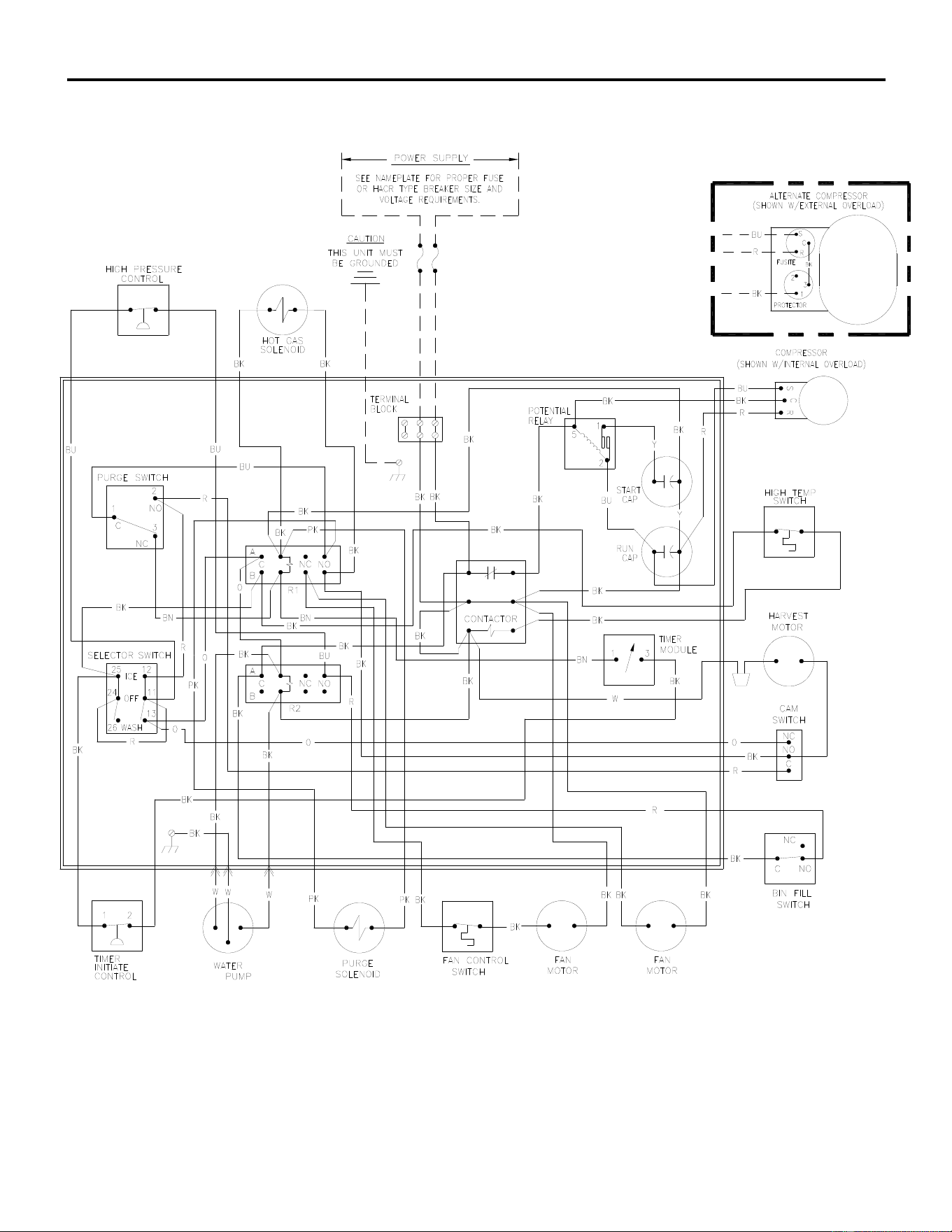
ICE Series Wiring Diagram
Page G59
ICE0325 Air3 and Water3, ICE0525 Air3 and Water3 Wiring Diagram
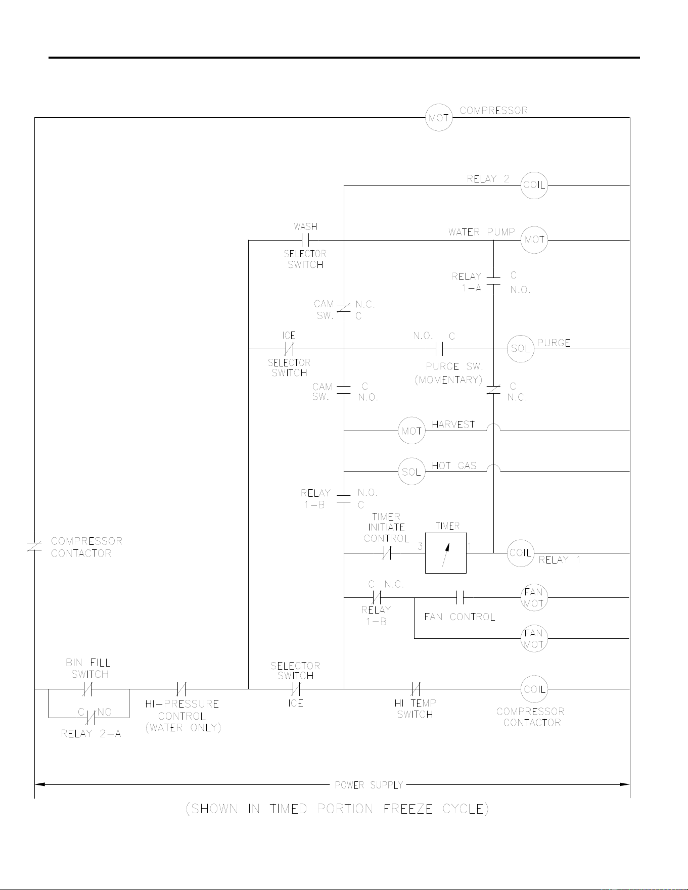
ICE Series Wiring Diagram
ICE0325 Air3 and Water3, ICE0525 Air3 and Water3 Wiring Schematic
Page G60
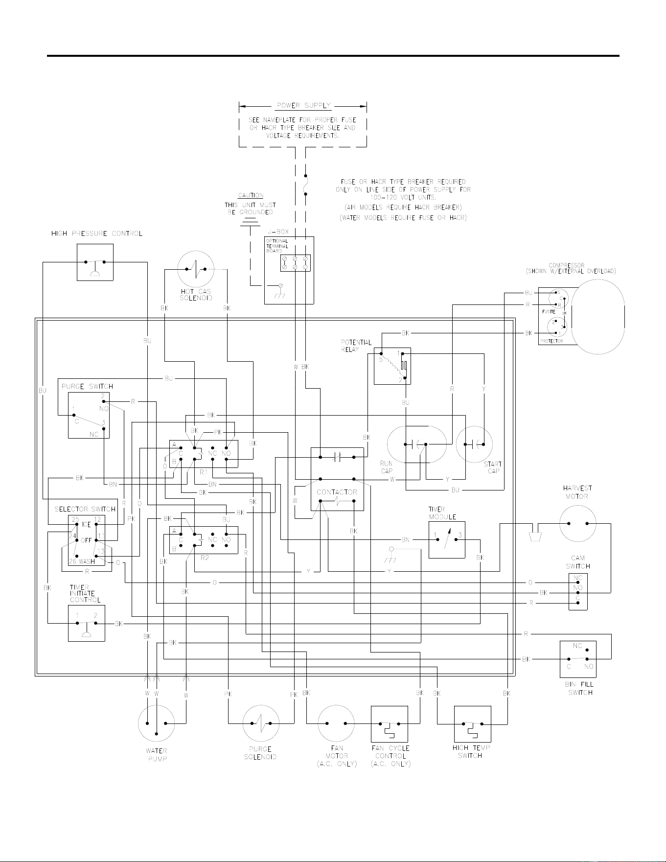
ICE Series Wiring Diagram
ICE0500 Air3 and Water3 Wiring Diagram
Page G61
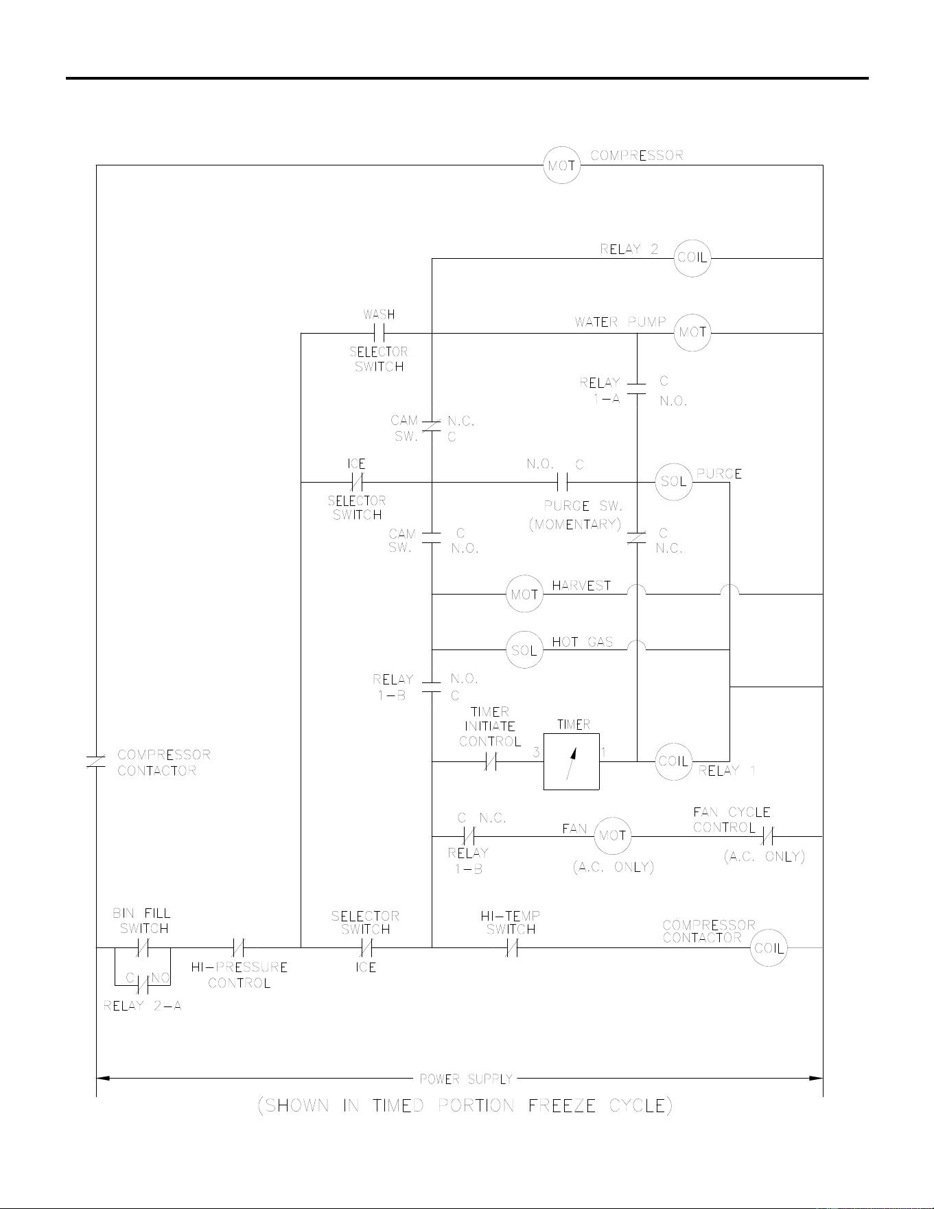
ICE Series Wiring Diagram
Page G62
ICE0500 Air3 and Water3 Wiring Schematic
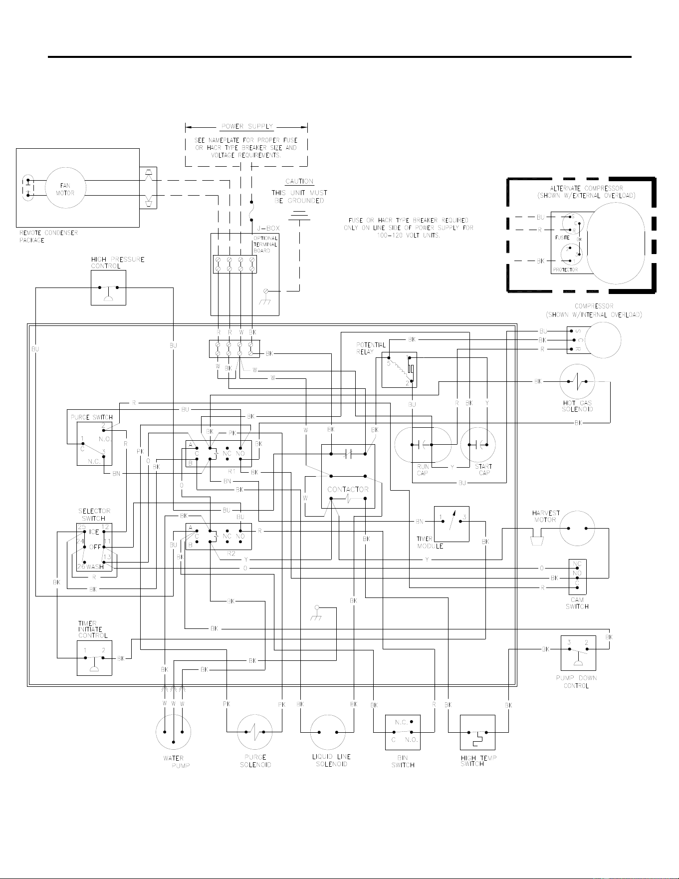
ICE Series Wiring Diagram
Page G63
ICE0500 Remote4 Wiring Diagram
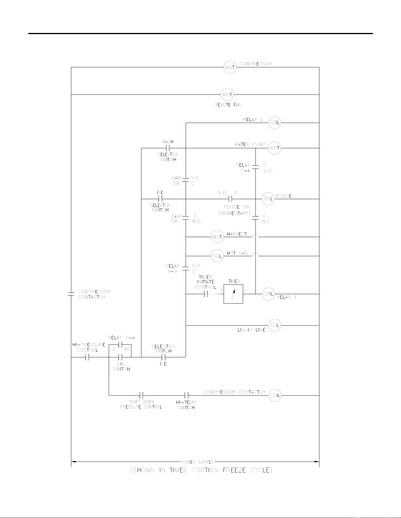
ICE Series Wiring Diagram
Page G64
ICE0500 Remote4 Wiring Schematic
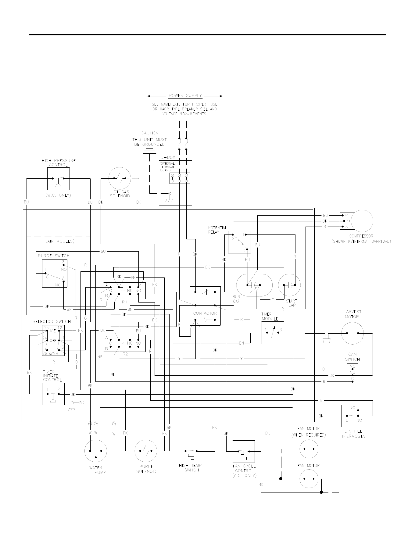
ICE Series Wiring Diagram
Page G65
ICE0606 Air3 and Water3, ICE0605 Air3 and Water3 Wiring Diagram
ICE0806 Air3 and Water3, ICE0805 Air3 and Water3 Wiring Diagram
ICE1006 Air3 and Water3, ICE1005 Air3 and Water3 Wiring Diagram
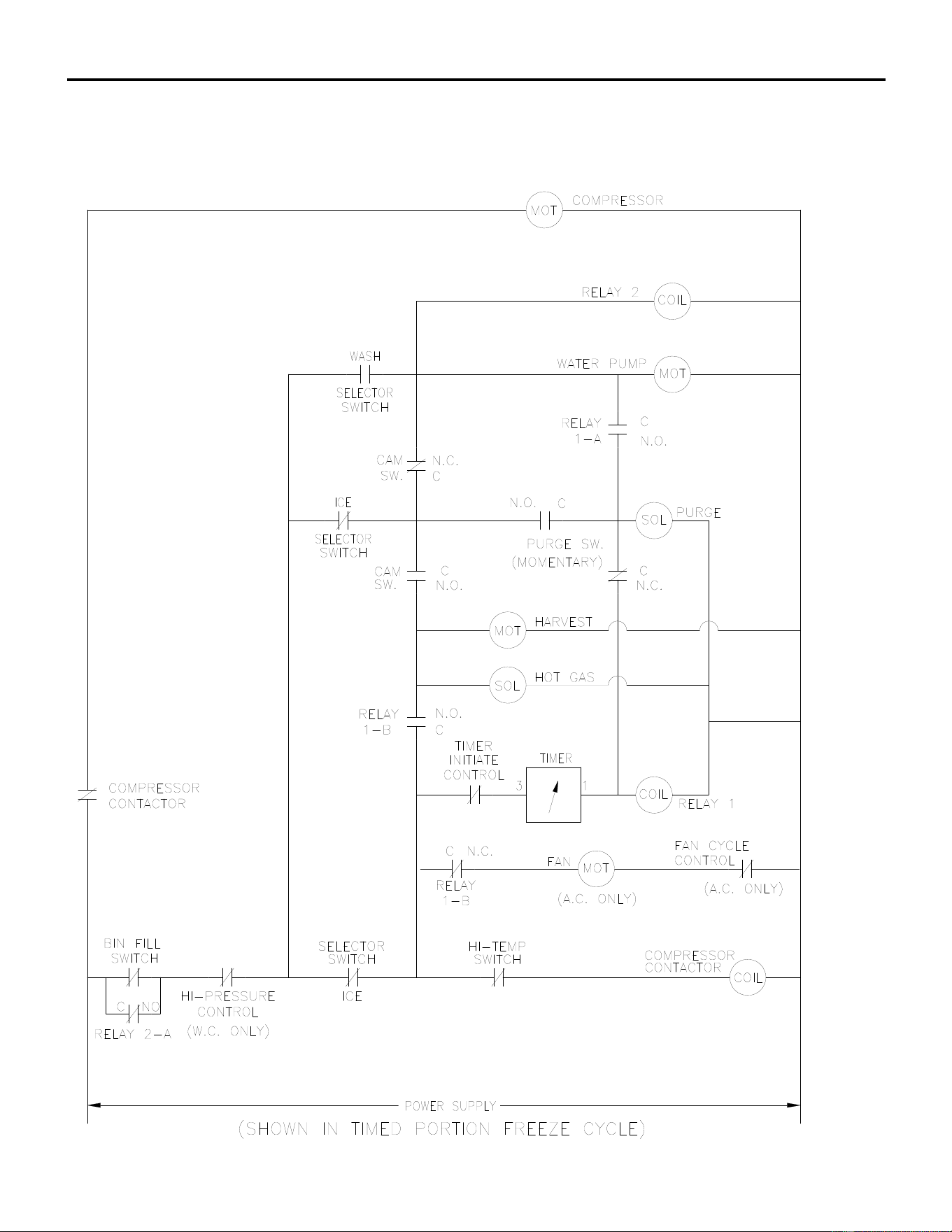
ICE Series Wiring Diagram
Page G66
ICE0606 Air3 and Water3, ICE0605 Air3 and Water3
ICE0806 Air3 and Water3, ICE0805 Air3 and Water3
ICE1006 Air3 and Water3, ICE1005 Air3 and Water3
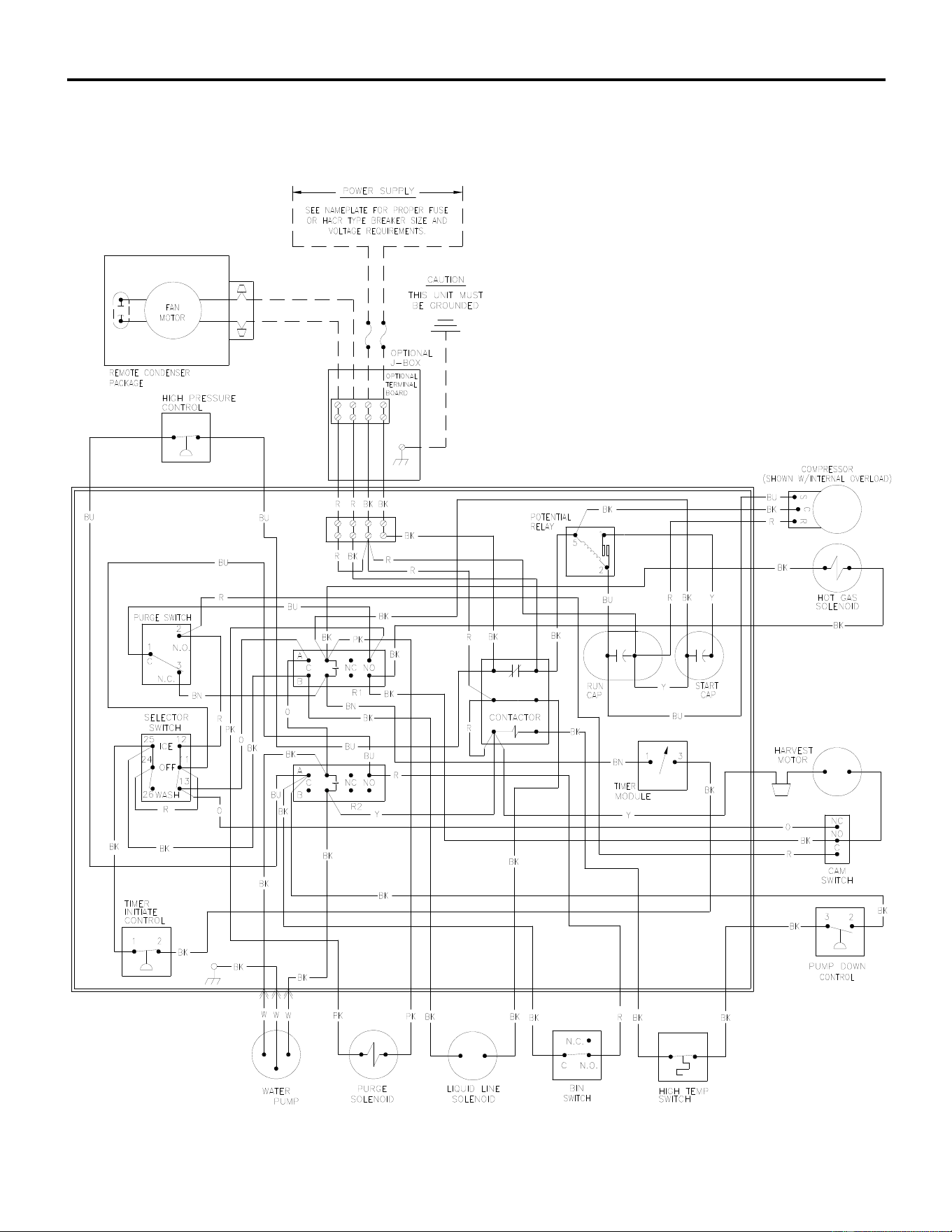
ICE Series Wiring Diagram
Page G67
ICE0606 Remote4&5 and ICE0605 Remote4&5 Wiring Diagram
ICE0806 Remote4 and ICE0805 Remote4 Wiring Diagram
ICE1006 Remote4 and ICE1005 Remote4 Wiring Diagram
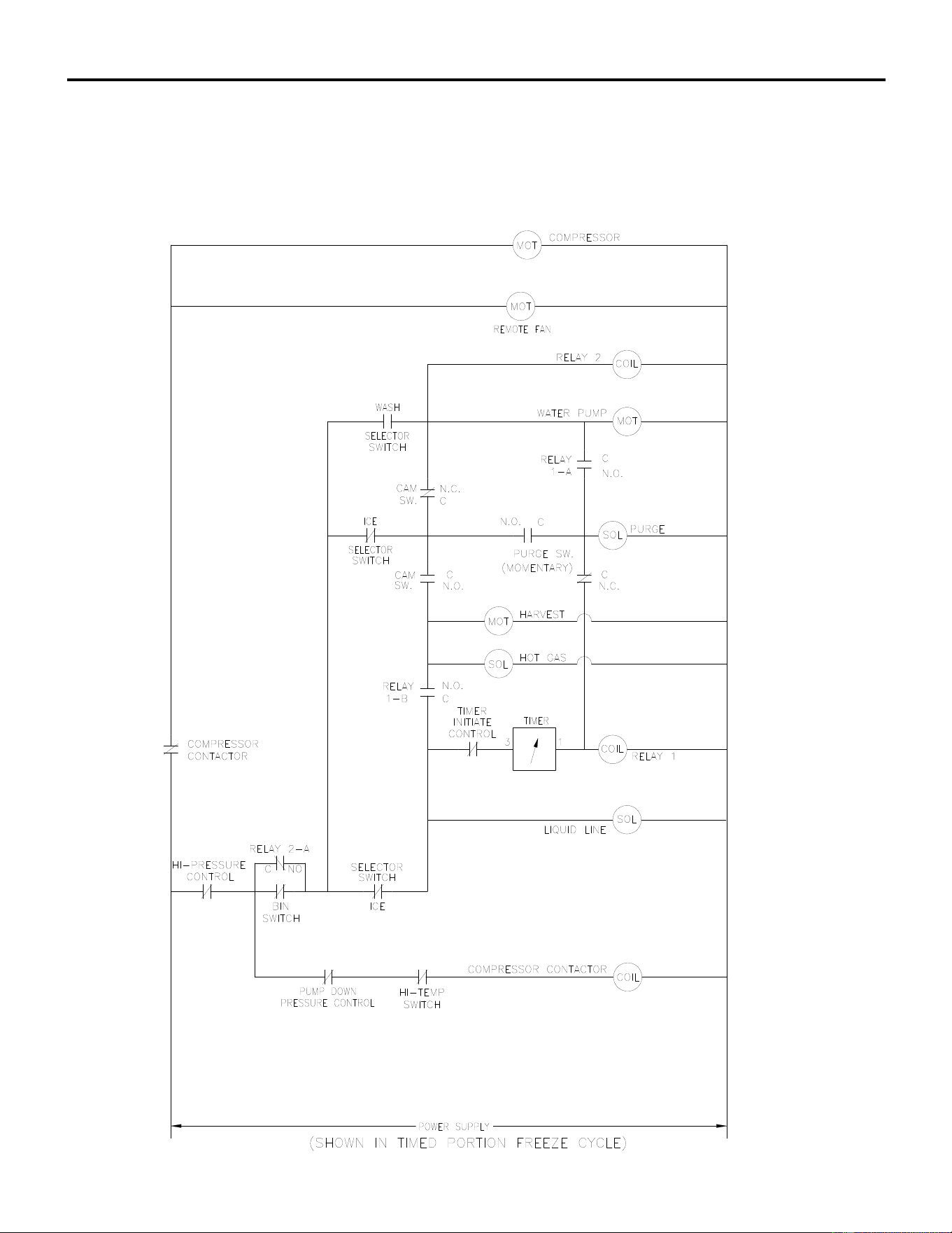
ICE Series Wiring Diagram
Page G68
ICE0606 Remote4&5 and ICE0605 Remote4&5 Wiring Schematic
ICE0806 Remote4 and ICE0805 Remote4 Wiring Schematic
ICE1006 Remote4 and ICE1005 Remote4 Wiring Schematic
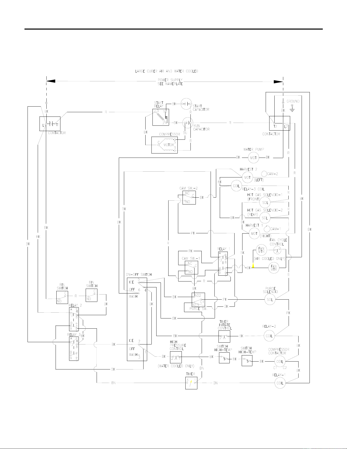
ICE Series Wiring Diagram
Page G69
ICE1405/6A3/W3, ICE1806W3 and ICE2106W3 Wiring Diagram
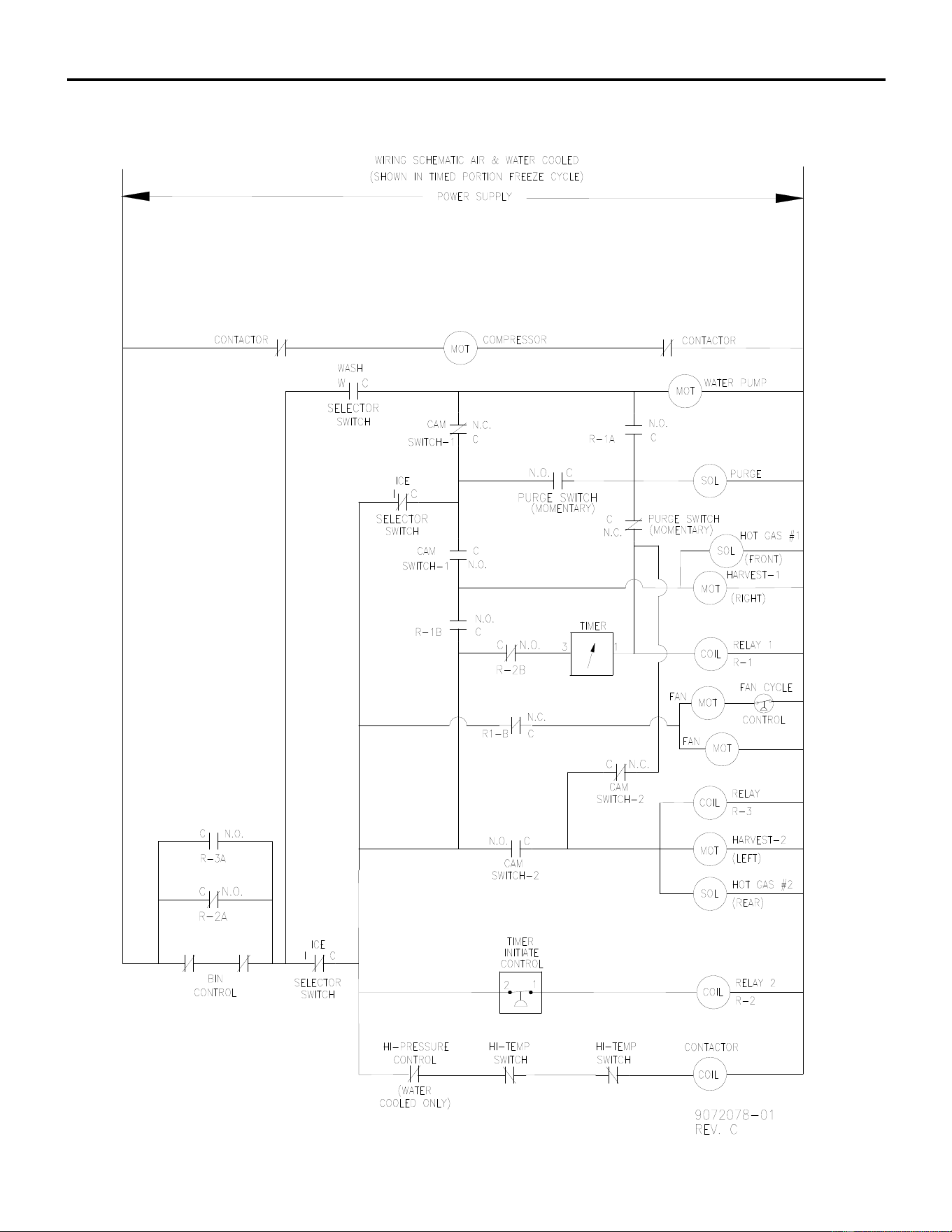
ICE Series Wiring Diagram
Page G70
ICE1405/6A3/W3, ICE1806W3 and ICE2106W3 Wiring Schematic
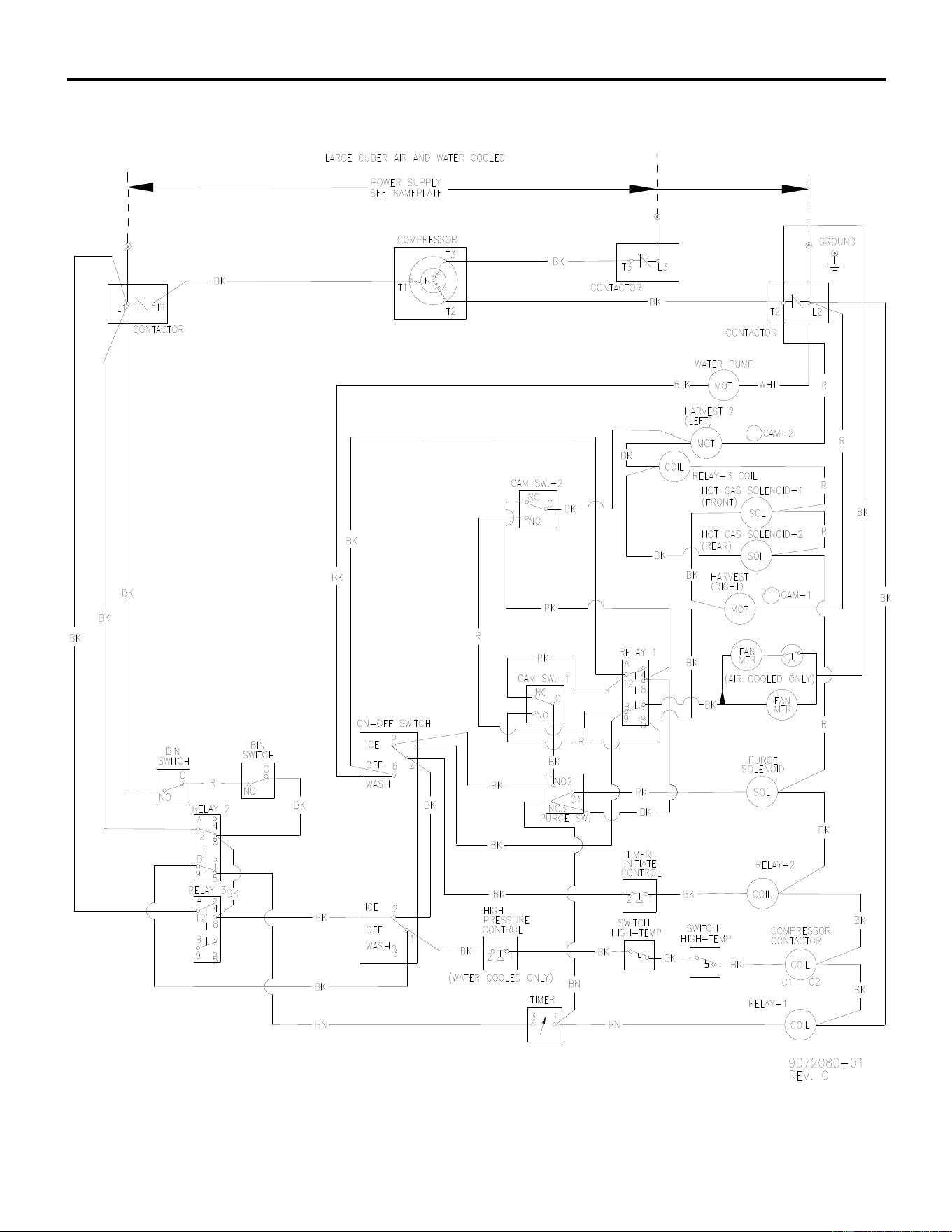
ICE Series Wiring Diagram
ICE1407A3/W3, ICE1807W3 and ICE2107W3 Wiring Diagram
Page G71
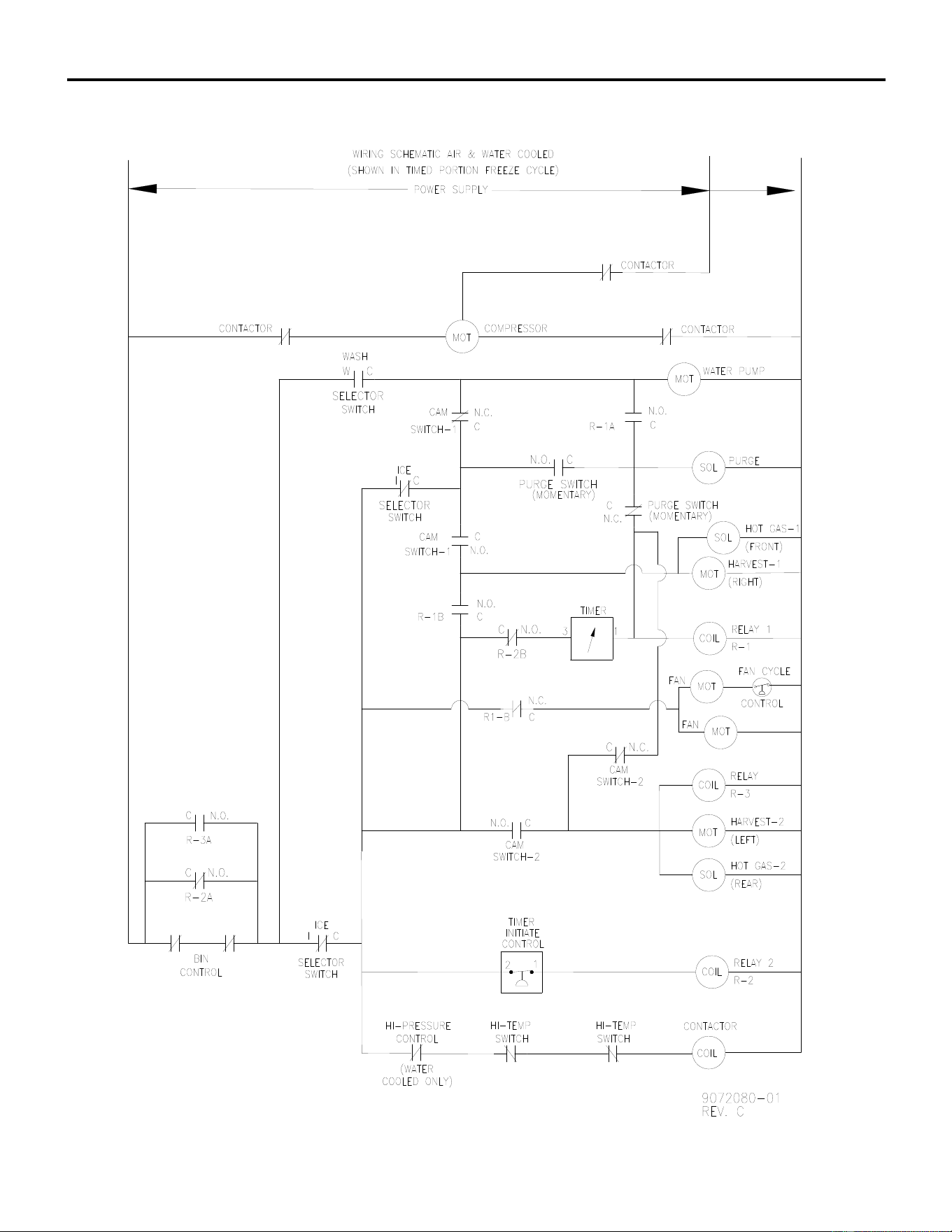
ICE Series Wiring Diagram
Page G72
ICE1407A3/W3, ICE1807W3 and ICE2107W3 Wiring Schematic
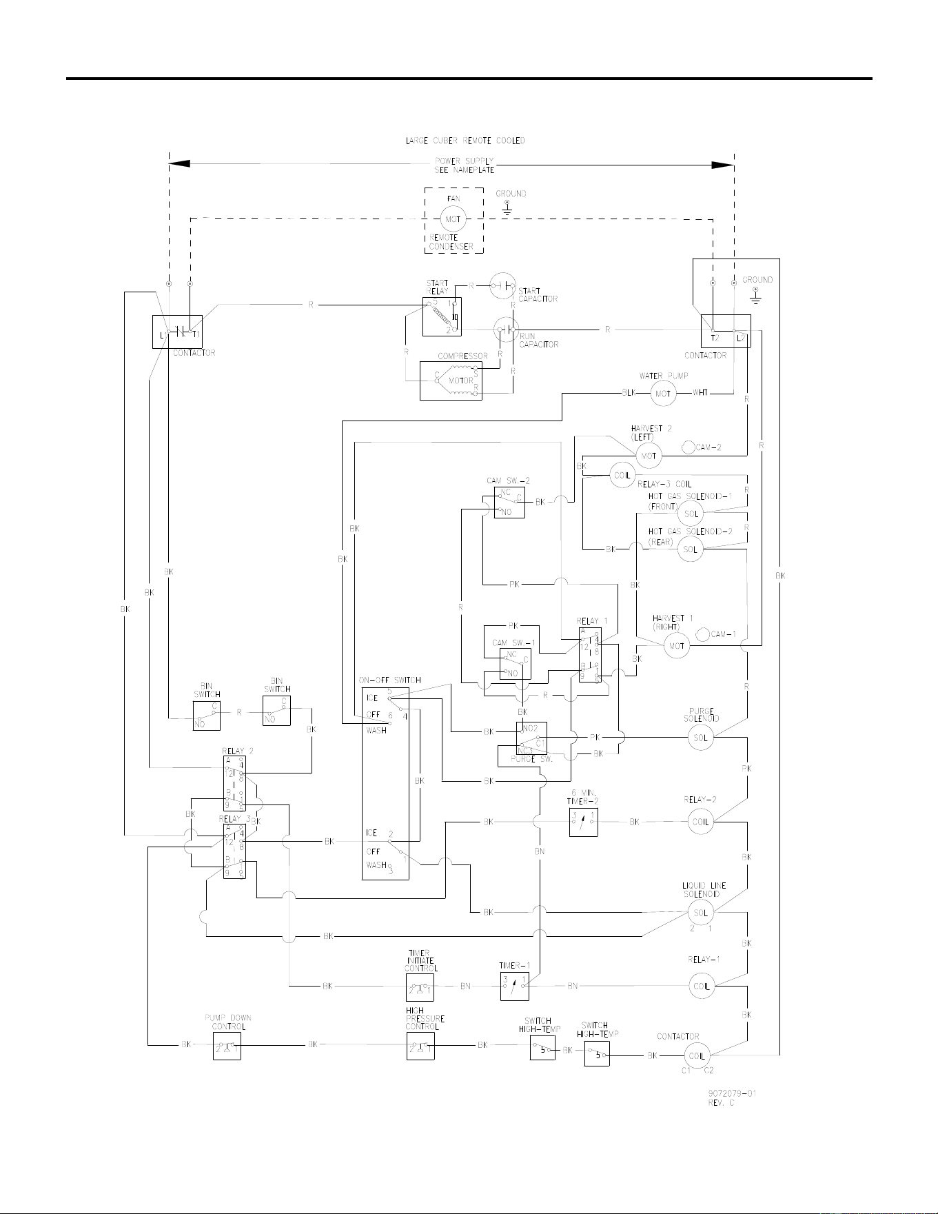
ICE Series Wiring Diagram
Page G73
ICE1405/6R3, ICE1806R3 and ICE2106R3 Wiring Diagram
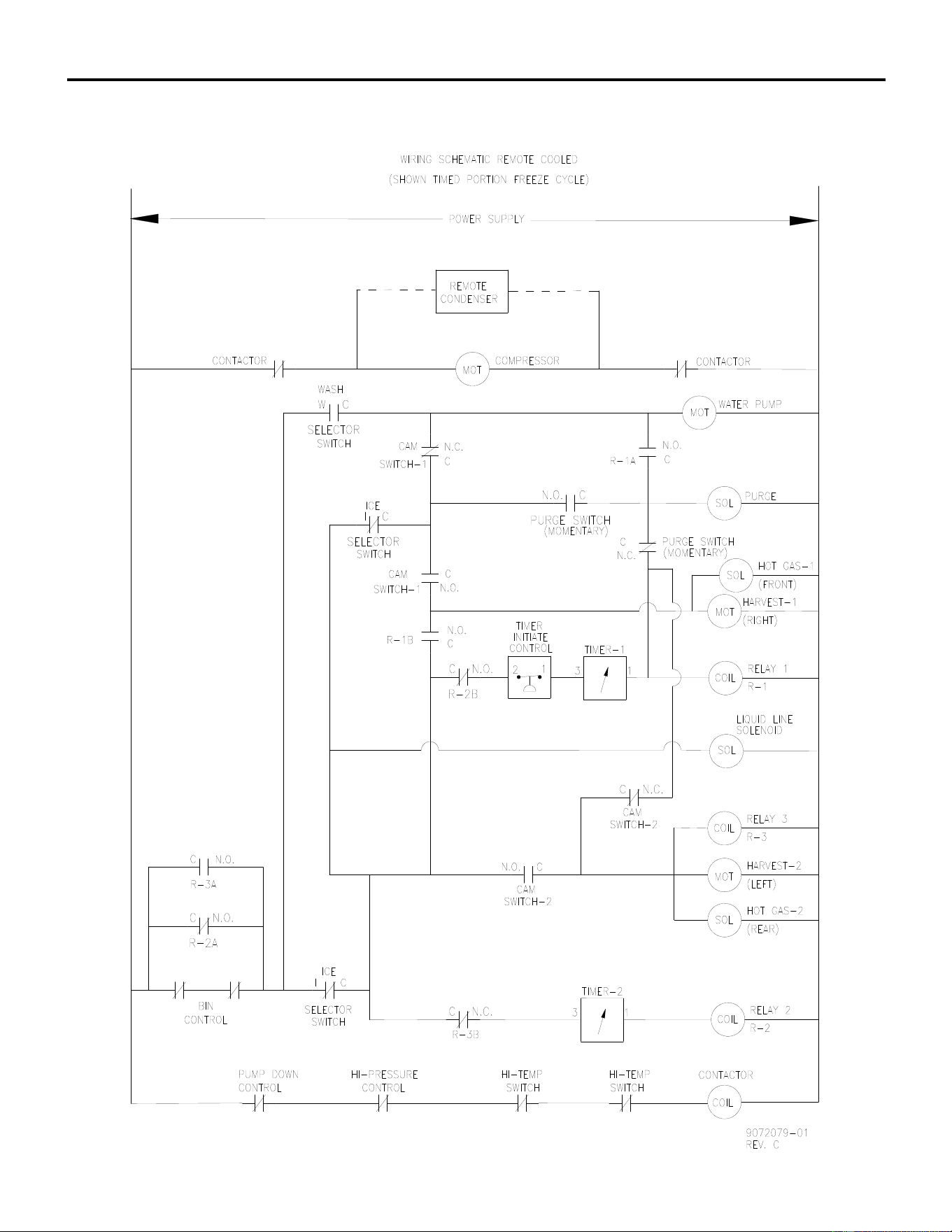
ICE Series Wiring Diagram
Page G74
ICE1405/6R3, ICE1806R3 and ICE2106R3 Wiring Schematic
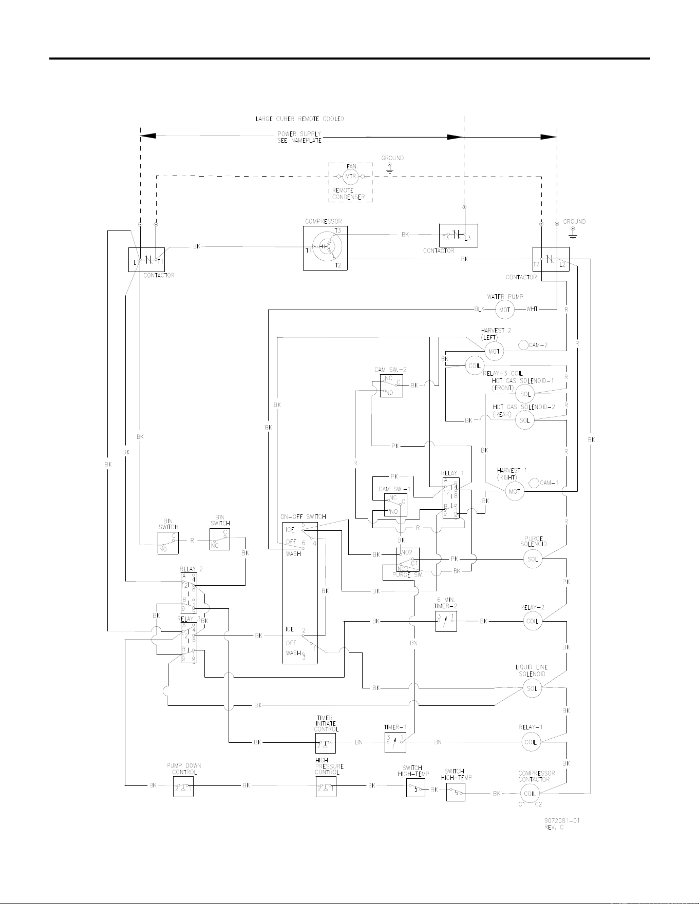
ICE Series Wiring Diagram
Page G75
ICE1407R3, ICE1807R3 and ICE2107R3 Wiring Diagram
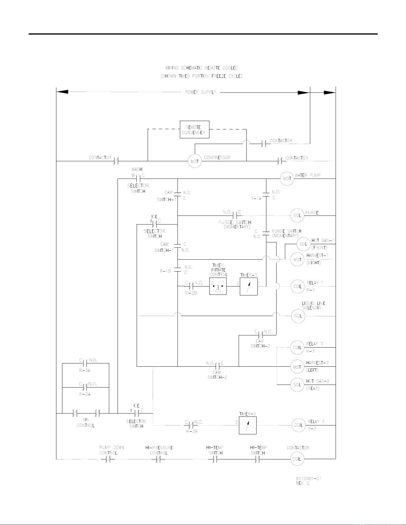
ICE Series Wiring Diagram
Page G76
ICE1407R3, ICE1807R3 and ICE2107R3 Wiring Schematic
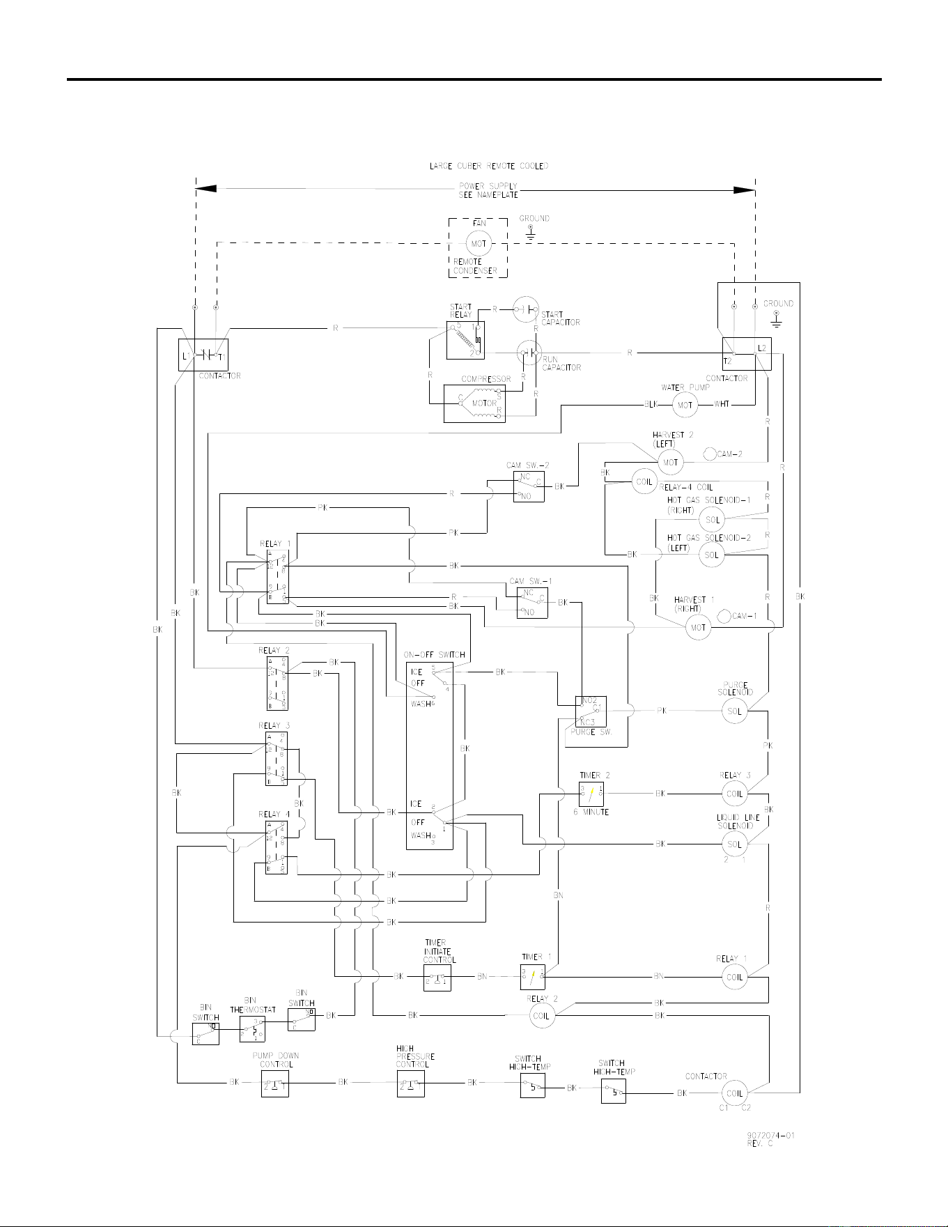
ICE Series Wiring Diagram
Page G77
ICE1506R3 Wiring Diagram
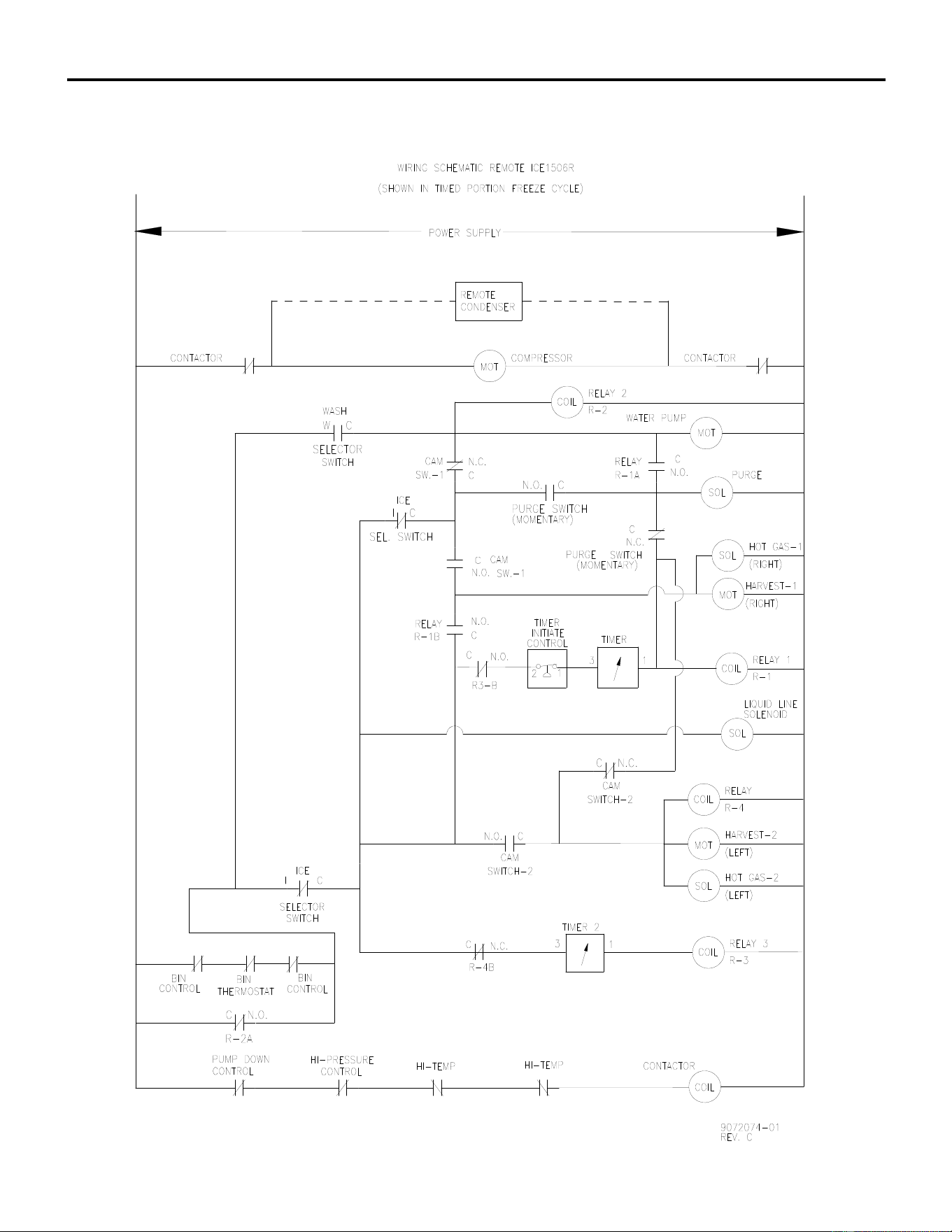
ICE Series Wiring Diagram
Page G78
ICE1506R3 Wiring Schematic
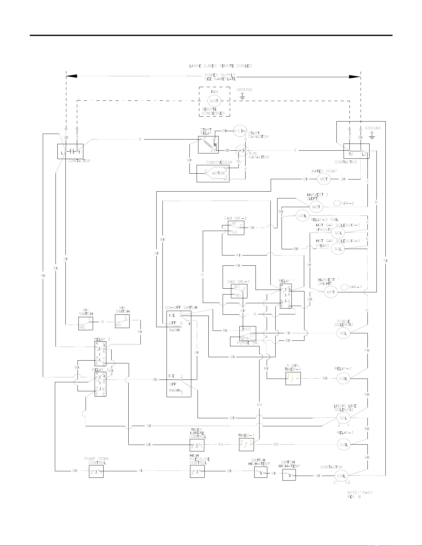
ICE Series Wiring Diagram
Page G79
ICE1406/5R, ICE1806R, ICE2106R Wiring Diagram, From Serial Number 09041280010342
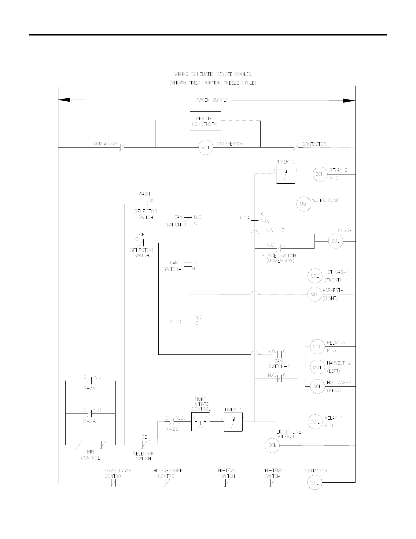
ICE Series Wiring Diagram
Page G80
ICE1406/5R, ICE1806R, ICE2106R Wiring Schematic, From Serial Number 09041280010342
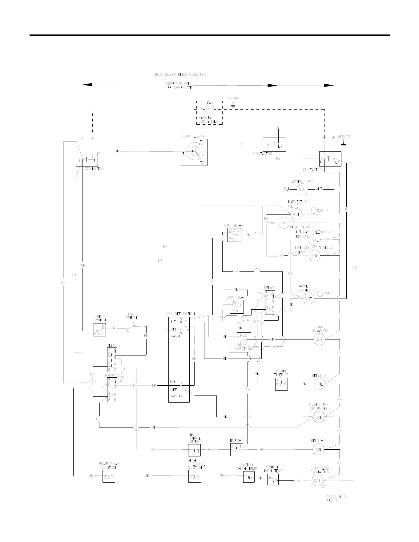
ICE Series Wiring Diagram
Page G81
ICE1407R, ICE1807R, ICE2107R Wiring Diagram, From Serial Number 09041280010342
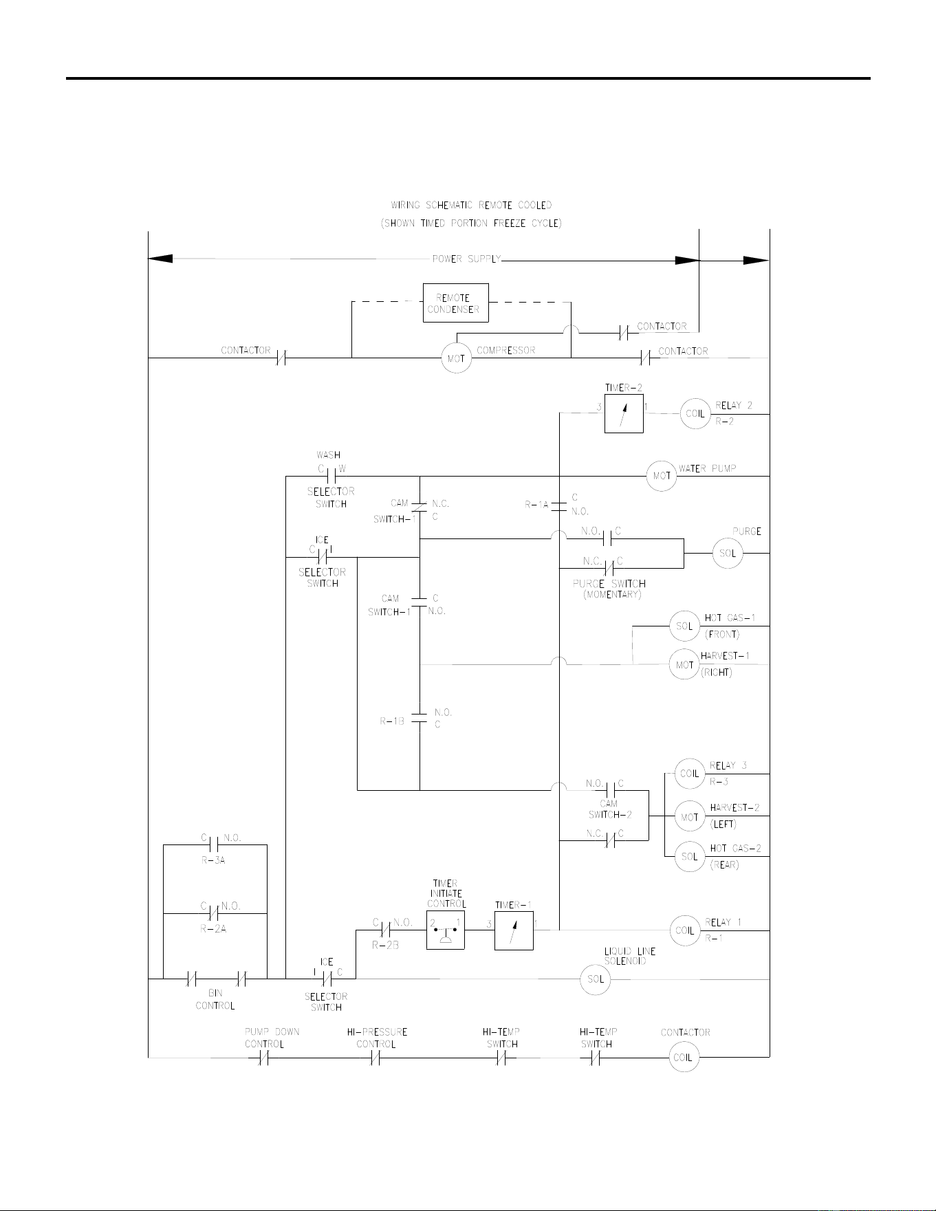
ICE Series Wiring Diagram
Page G82
ICE1407R, ICE1807R, ICE2107R Wiring Schematic, From Serial Number 09041280010342
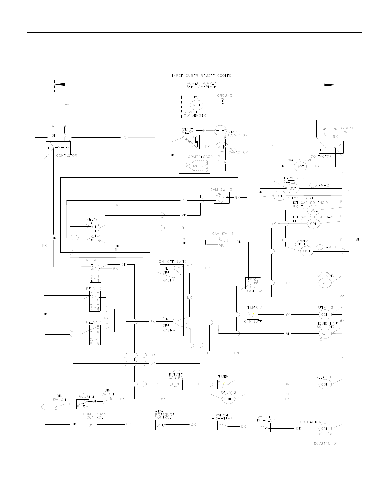
ICE Series Wiring Diagram
Page G83
ICE1506R3 Wiring Diagram From Serial Number 09041280010750
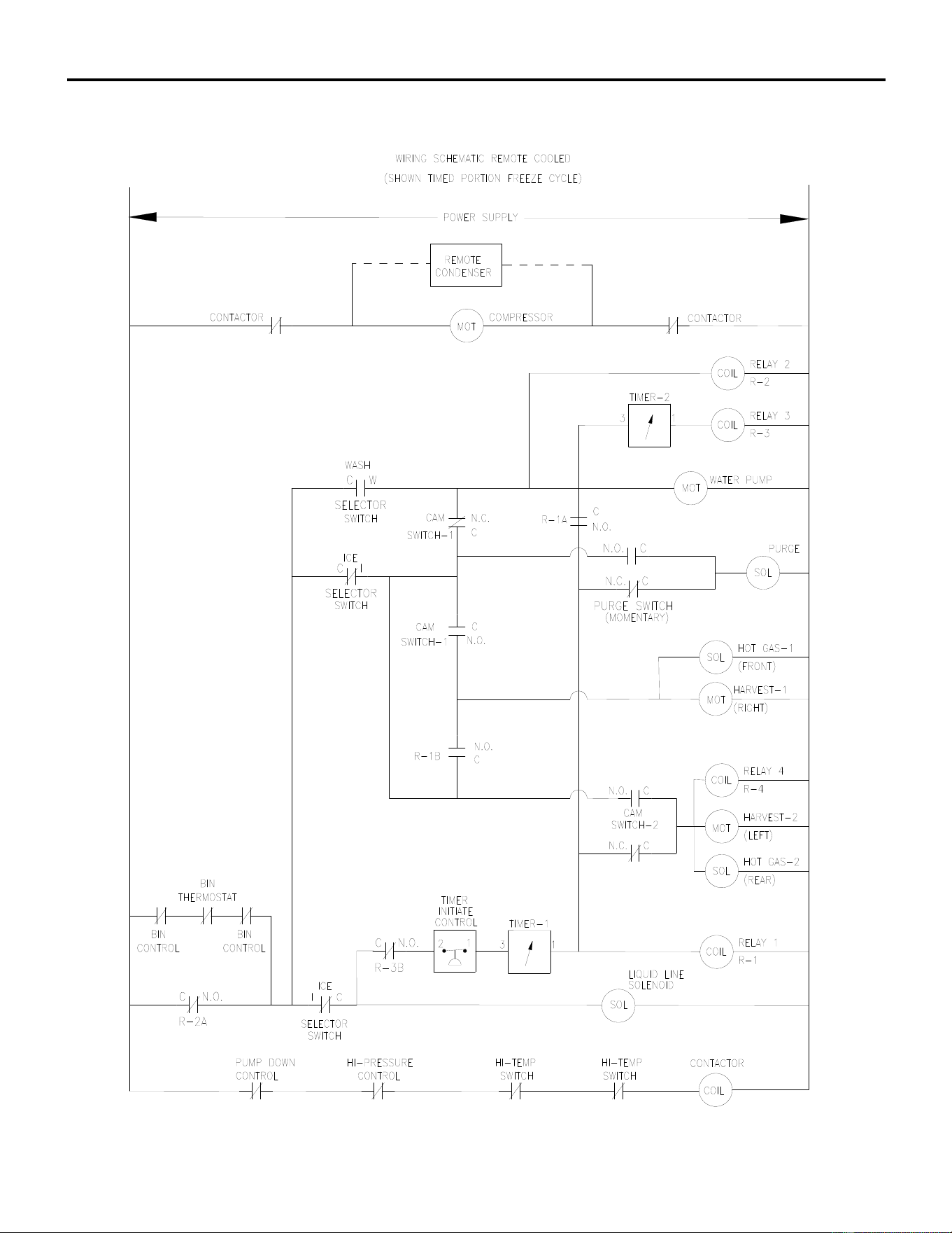
ICE Series Wiring Diagram
Page G84
ICE1506R3 Wiring Schematic From Serial Number 09041280010750
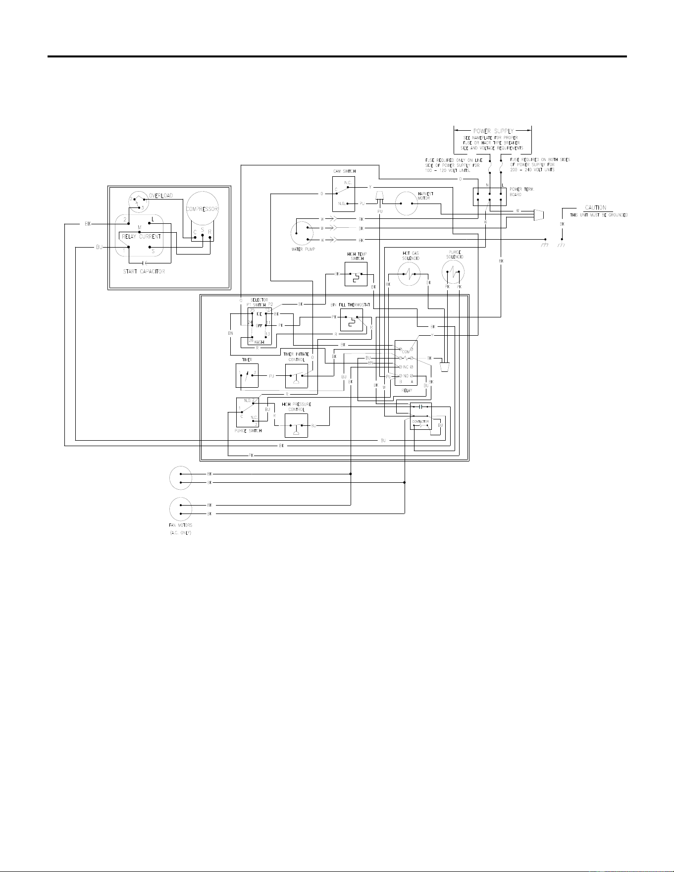
ICE Series Wiring Diagram
Page G85
ICEU300A/W Wiring Diagram From Serial Number 10041280011405
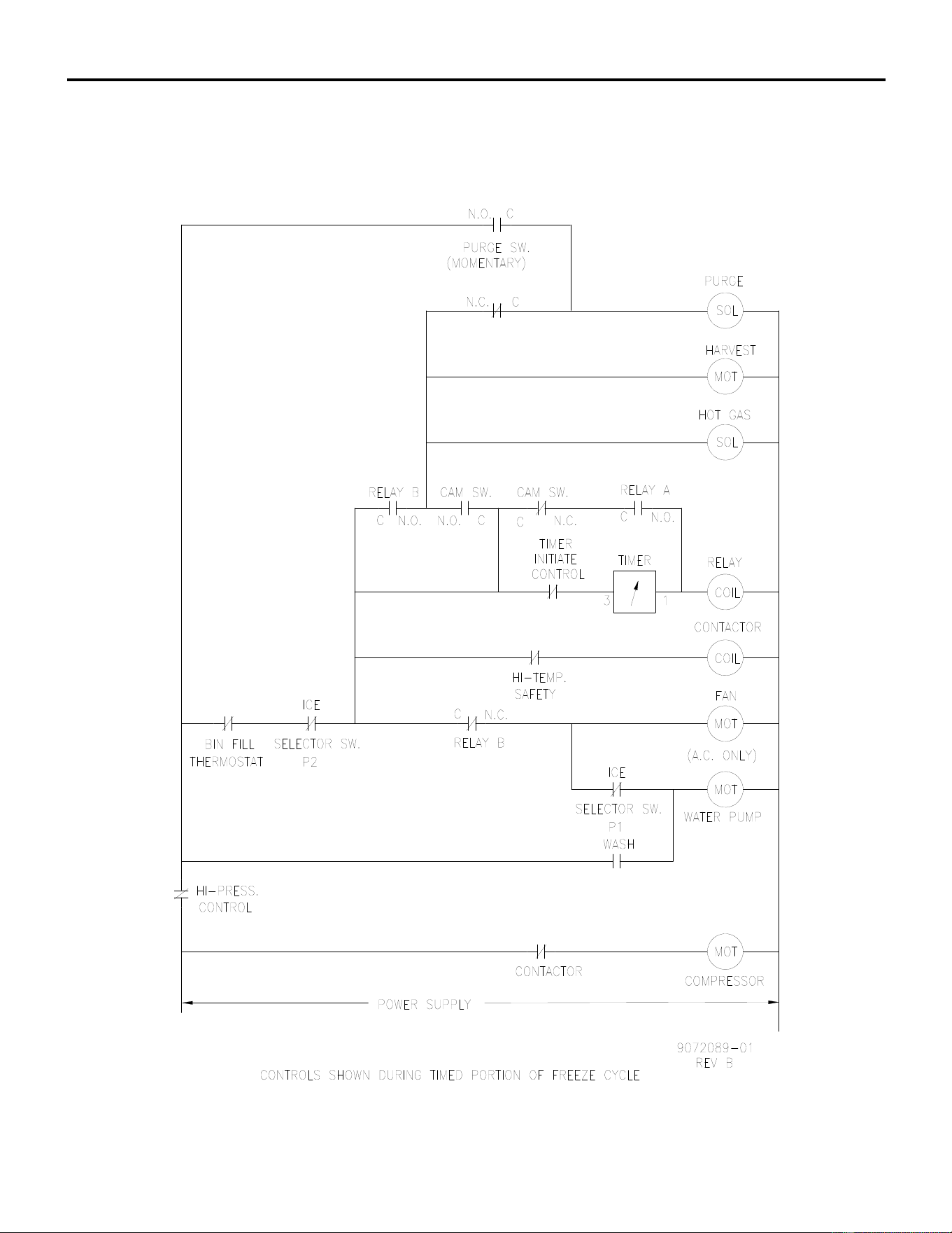
ICE Series Wiring Diagram
Page G86
ICEU300 A/W Wiring Schematic From Serial Number 10041280011405
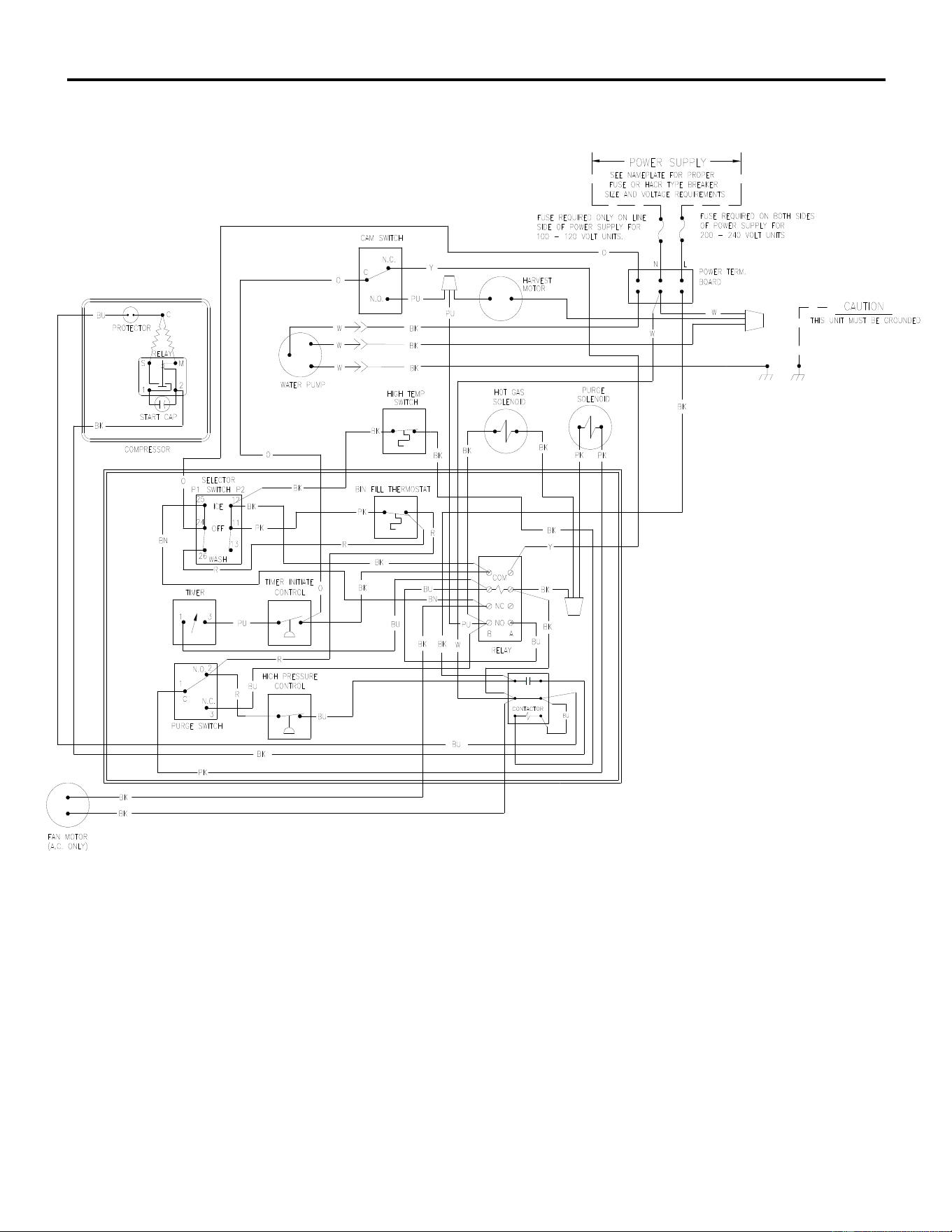
ICE Series Wiring Diagram
Page G87
ICEU150-220-225-226 A/W Wiring Diagram From Serial Number 10041280011405
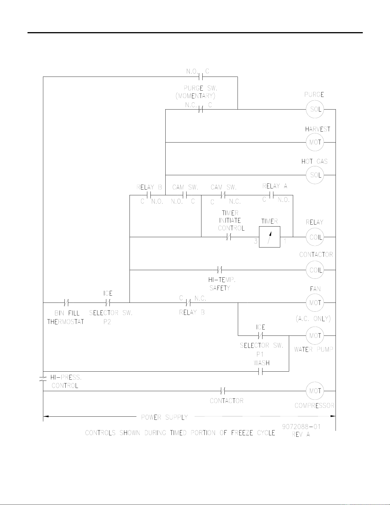
ICE Series Wiring Diagram
Page G88
ICEU150-220-225-226 A/W Wiring Schematic From Serial Number 10041280011405
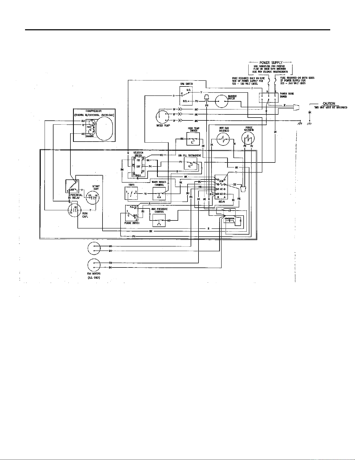
ICE Series Wiring Diagram
Page G89
ICEU305A/W Wiring Diagram From Serial Number 10041280011405
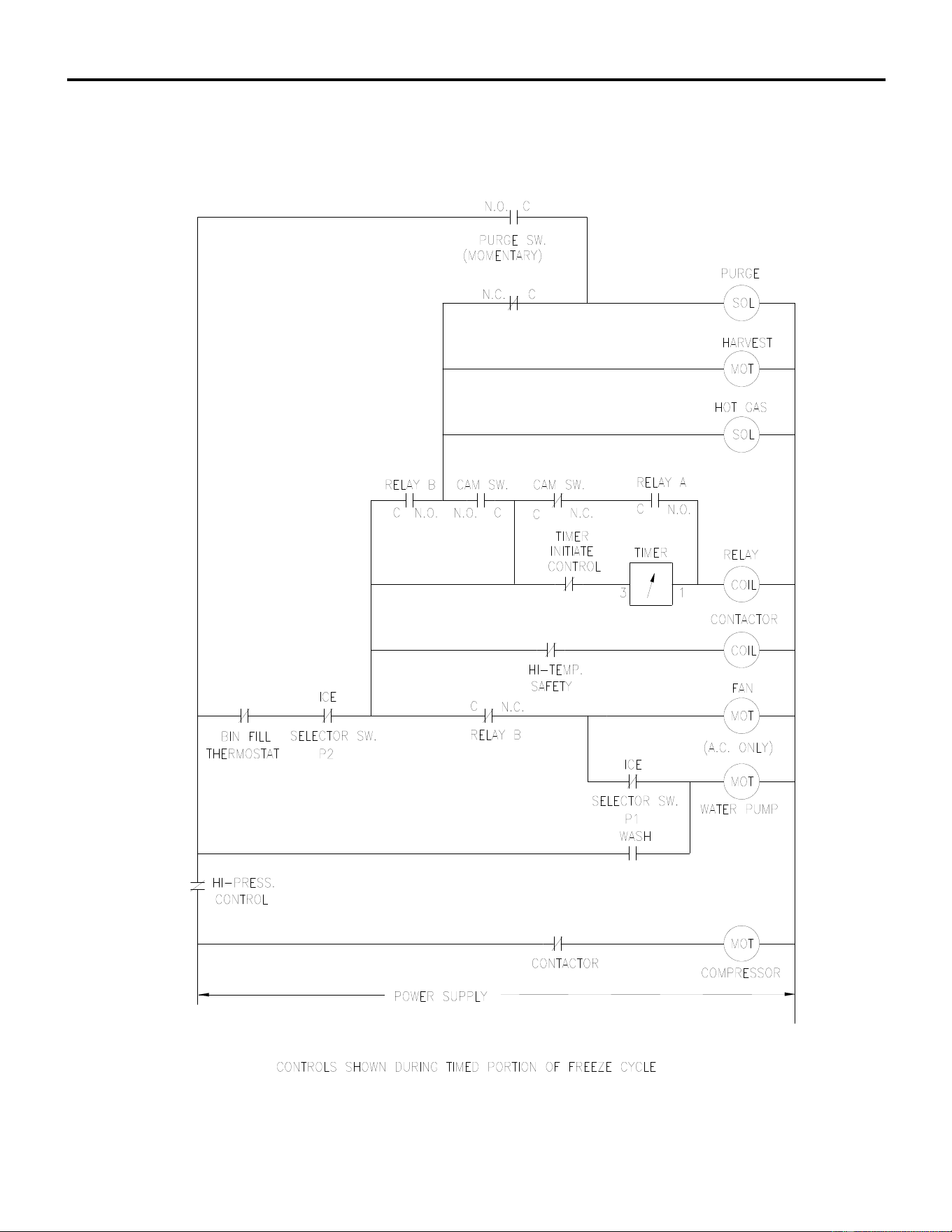
ICE Series Wiring Diagram
Page G90
ICEU305 A/W Wiring Schematic From Serial Number 10041280011405
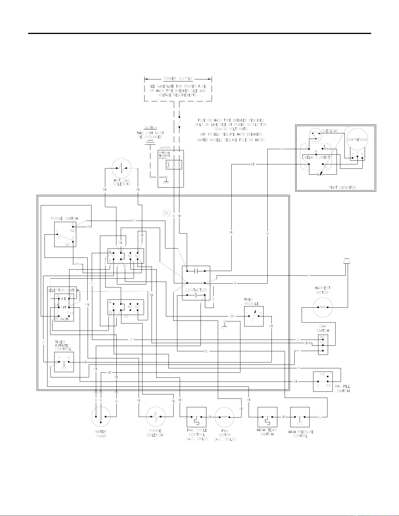
ICE Series Wiring Diagram
Page G91
ICE0400A5/400T6 Wiring Diagram
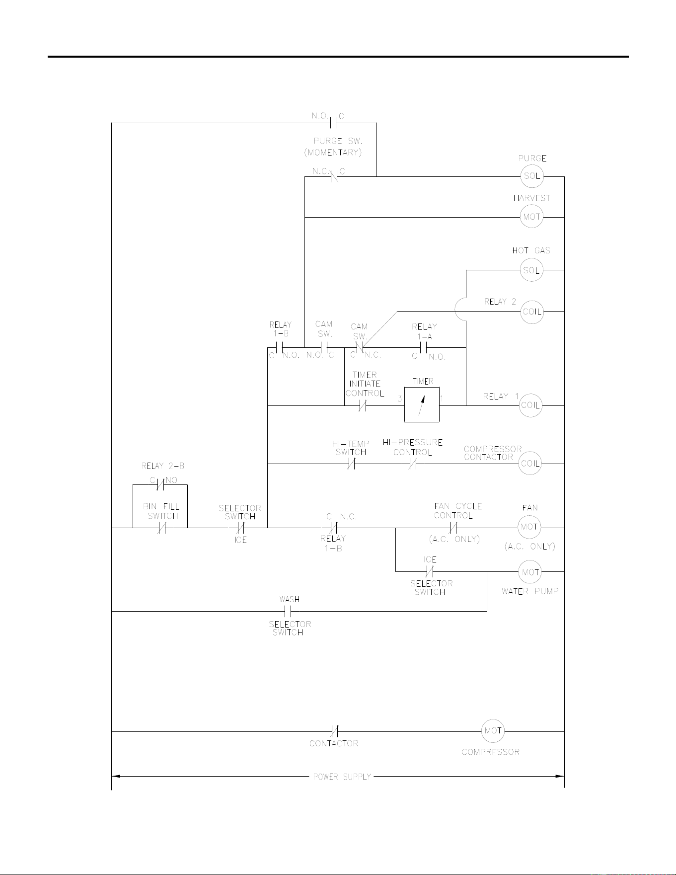
ICE Series Wiring Diagram
Page G92
ICE0400A5/400T6 Wiring Schematic
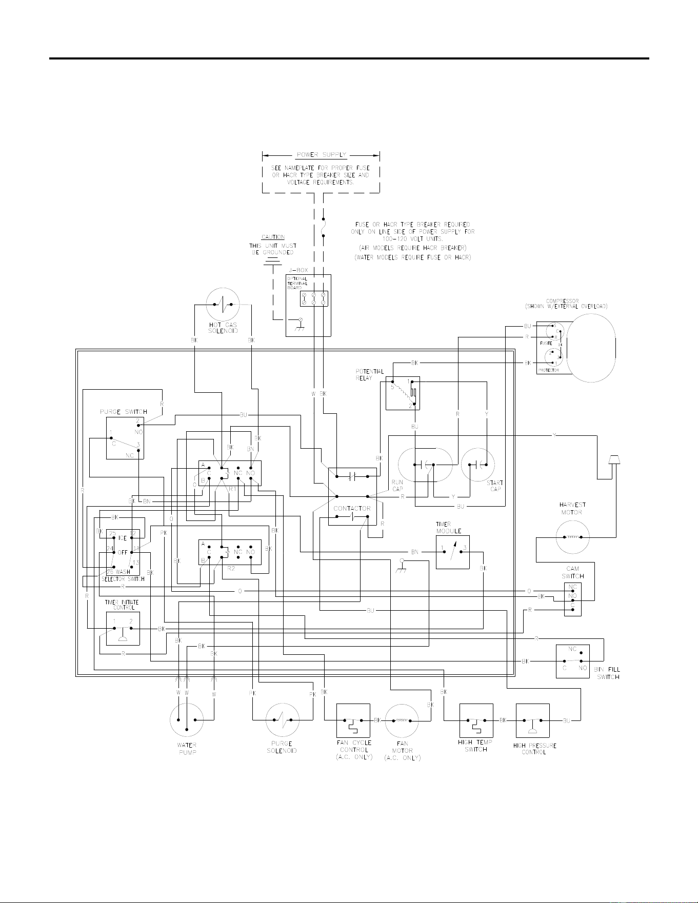
ICE Series Wiring Diagram
Page G93
ICE0500A5/500T6 Wiring Diagram
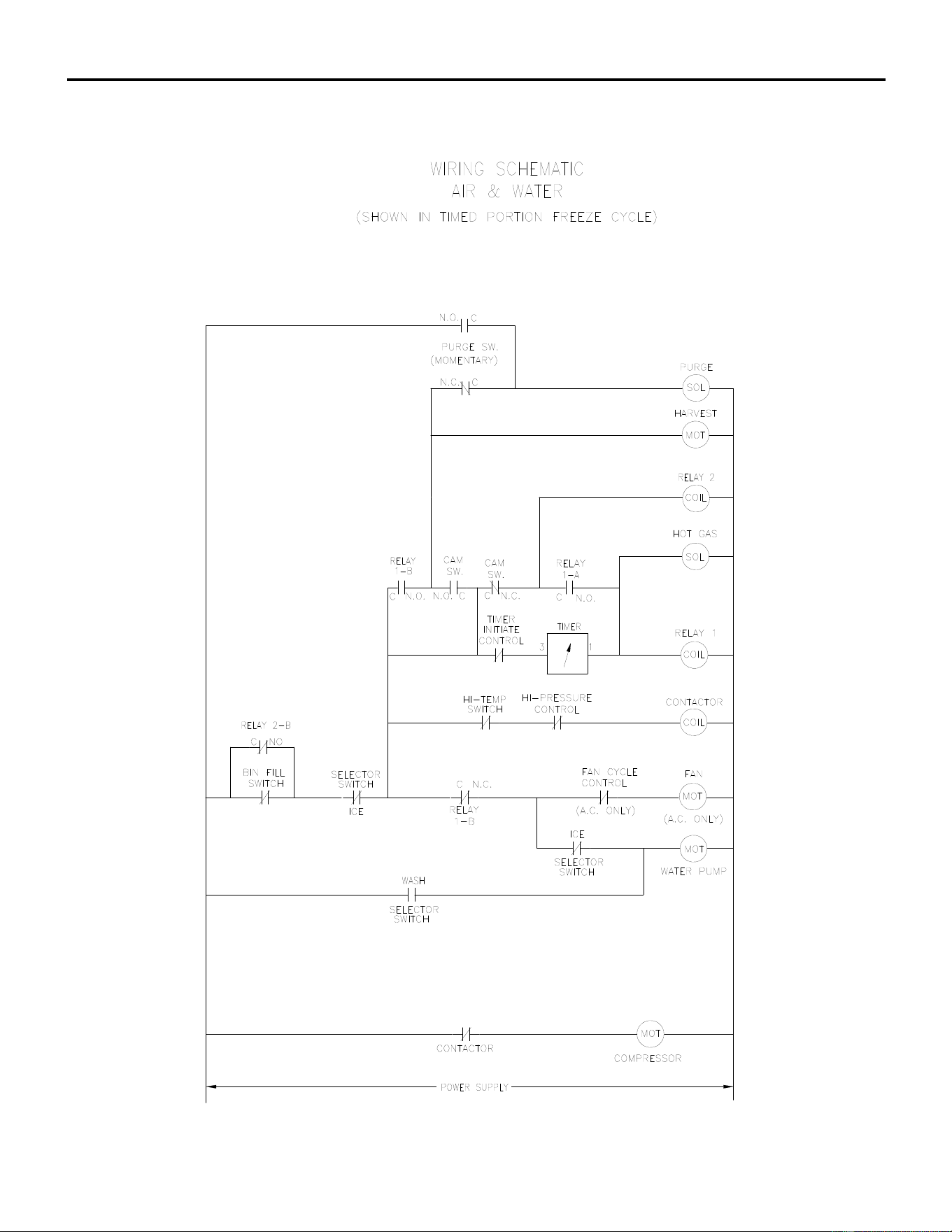
ICE Series Wiring Diagram
Page G94
ICE0500A5/500T6 Wiring Schematic
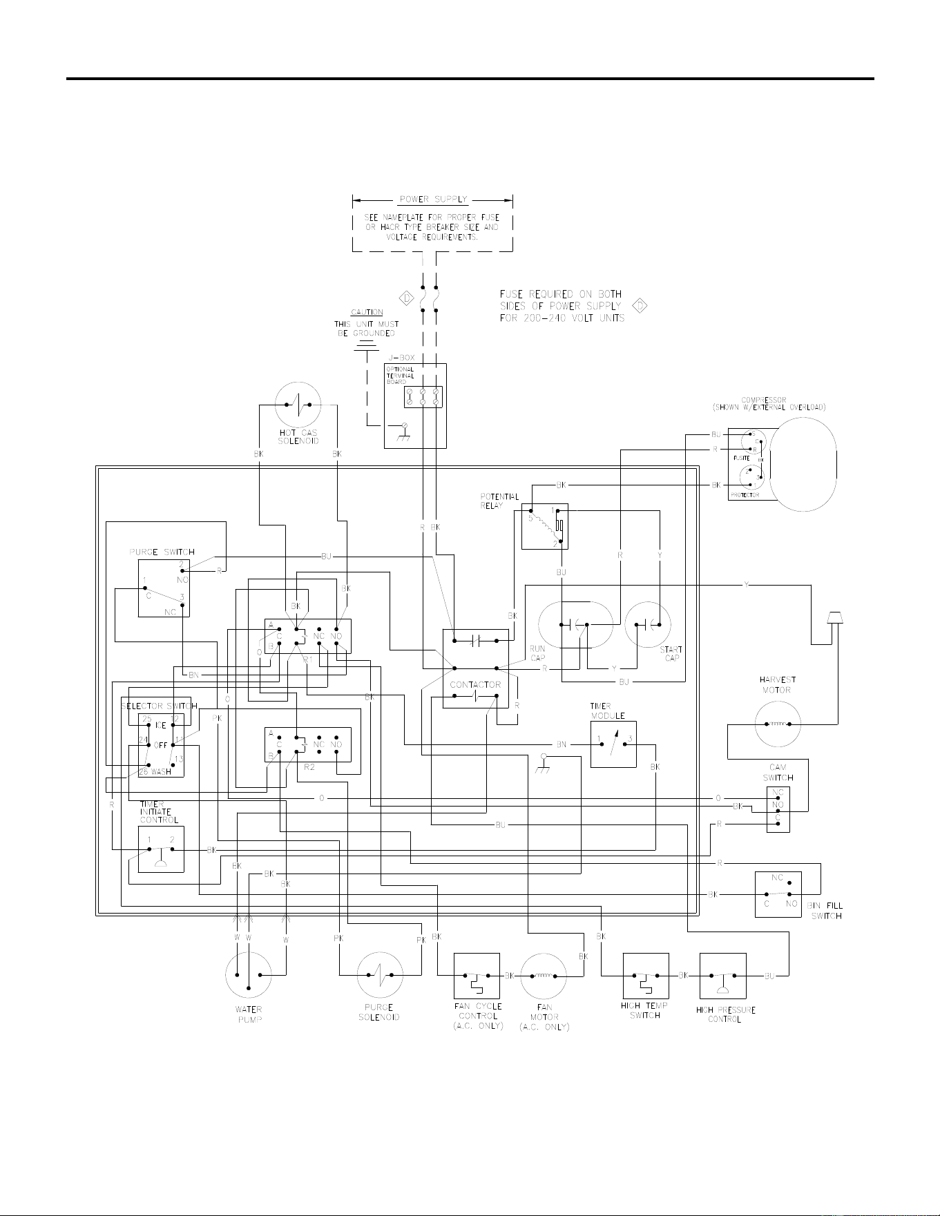
ICE Series Wiring Diagram
Page G95
ICE0606A5/606T6 Wiring Diagram
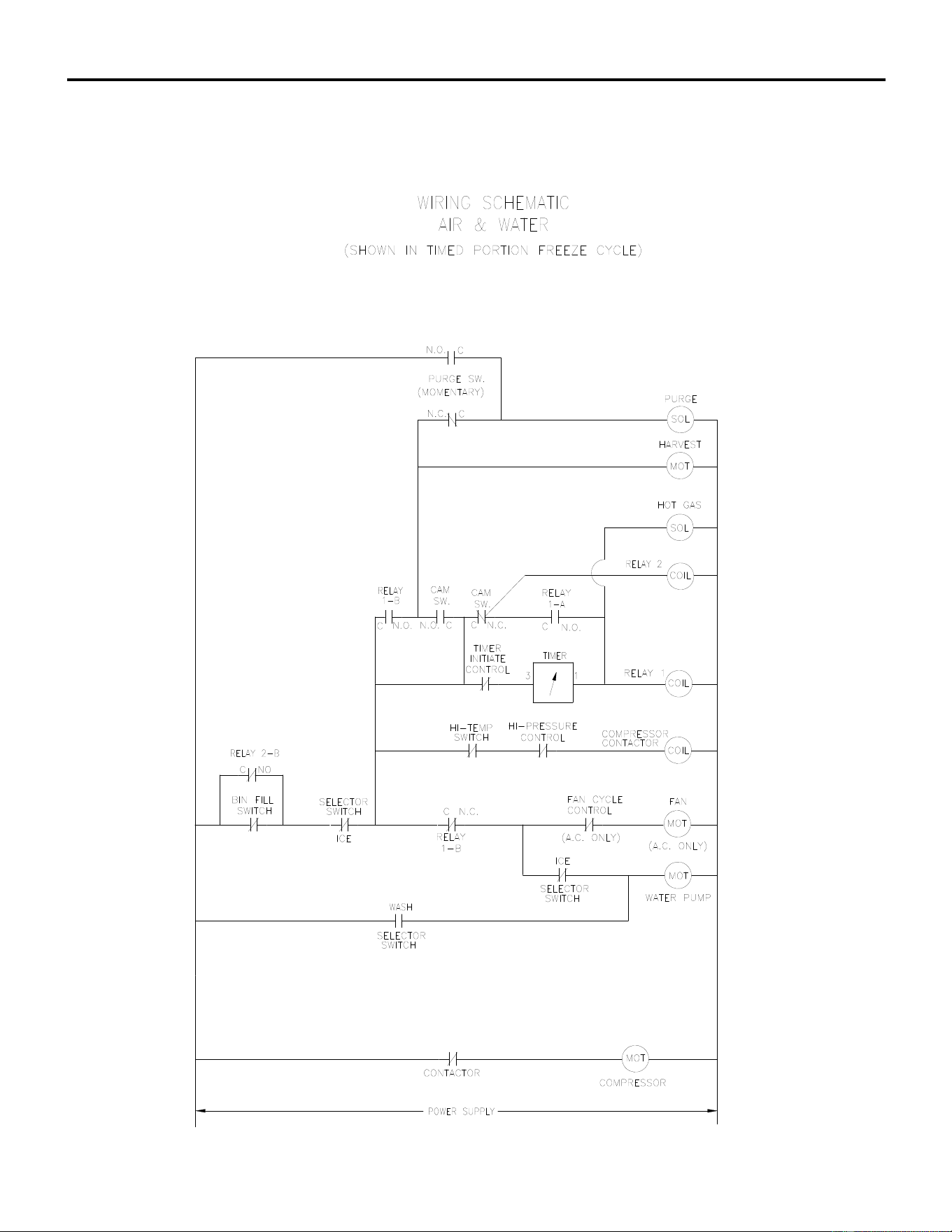
ICE Series Wiring Diagram
Page G96
ICE0606A5/606T6 Wiring Schematic
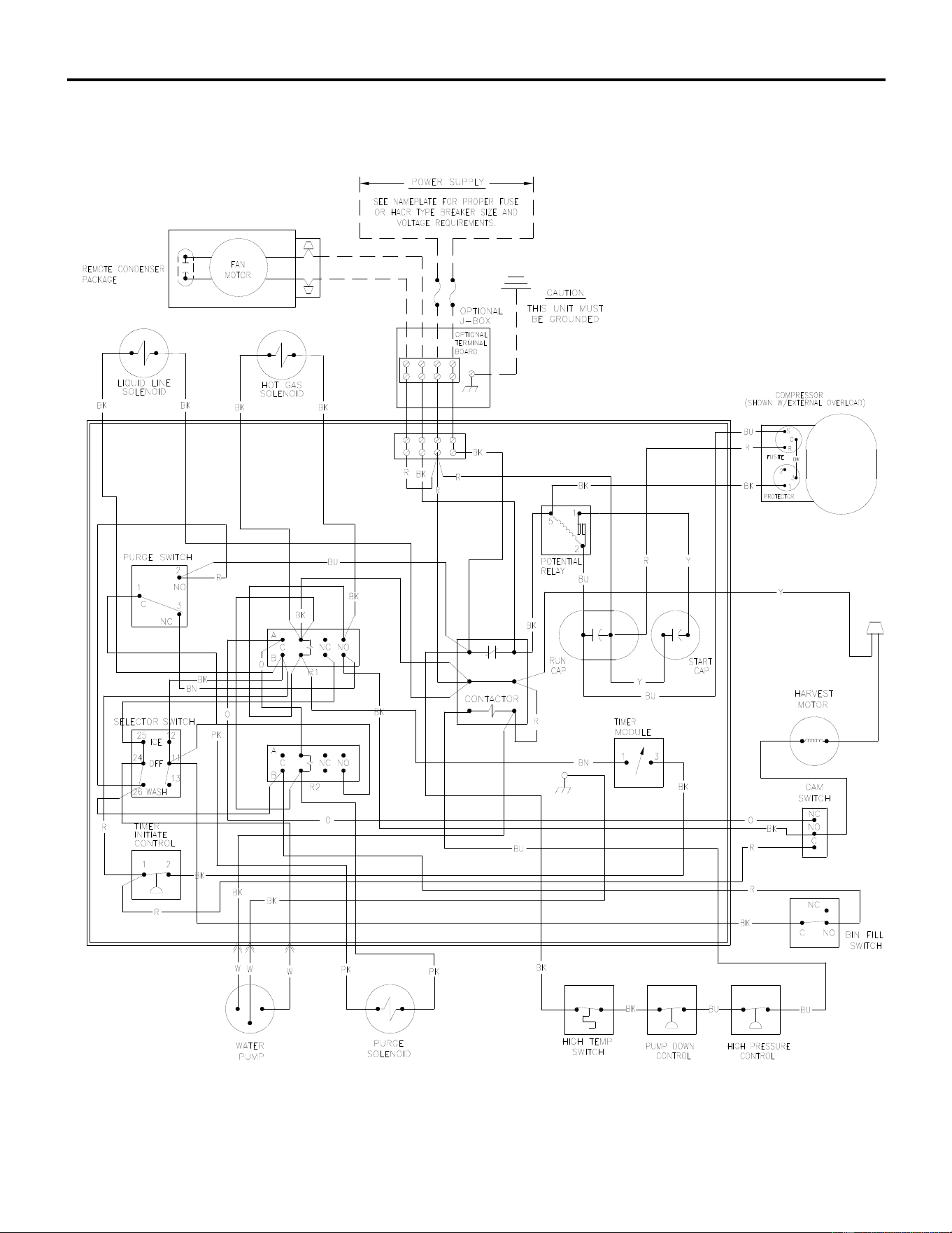
ICE Series Wiring Diagram
Page G97
ICE0606R6/605R6 Wiring Diagram
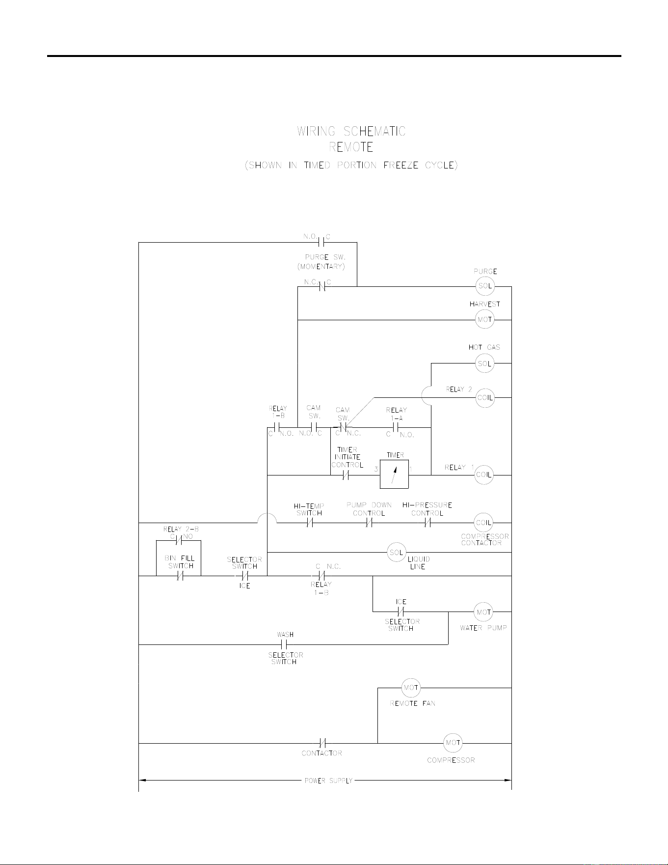
ICE Series Wiring Diagram
Page G98
ICE0606R6/605R6 Wiring Schematic
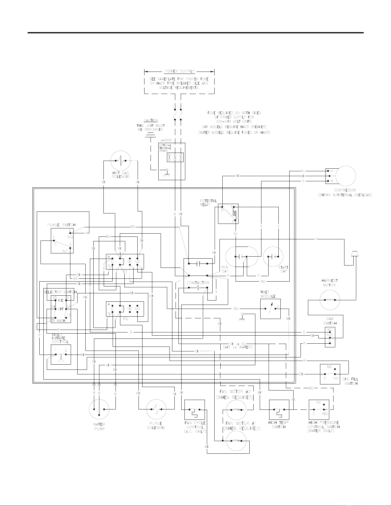
ICE Series Wiring Diagram
Page G99
ICE1006A5-W4/ICE0806A5-W5 Wiring Diagram
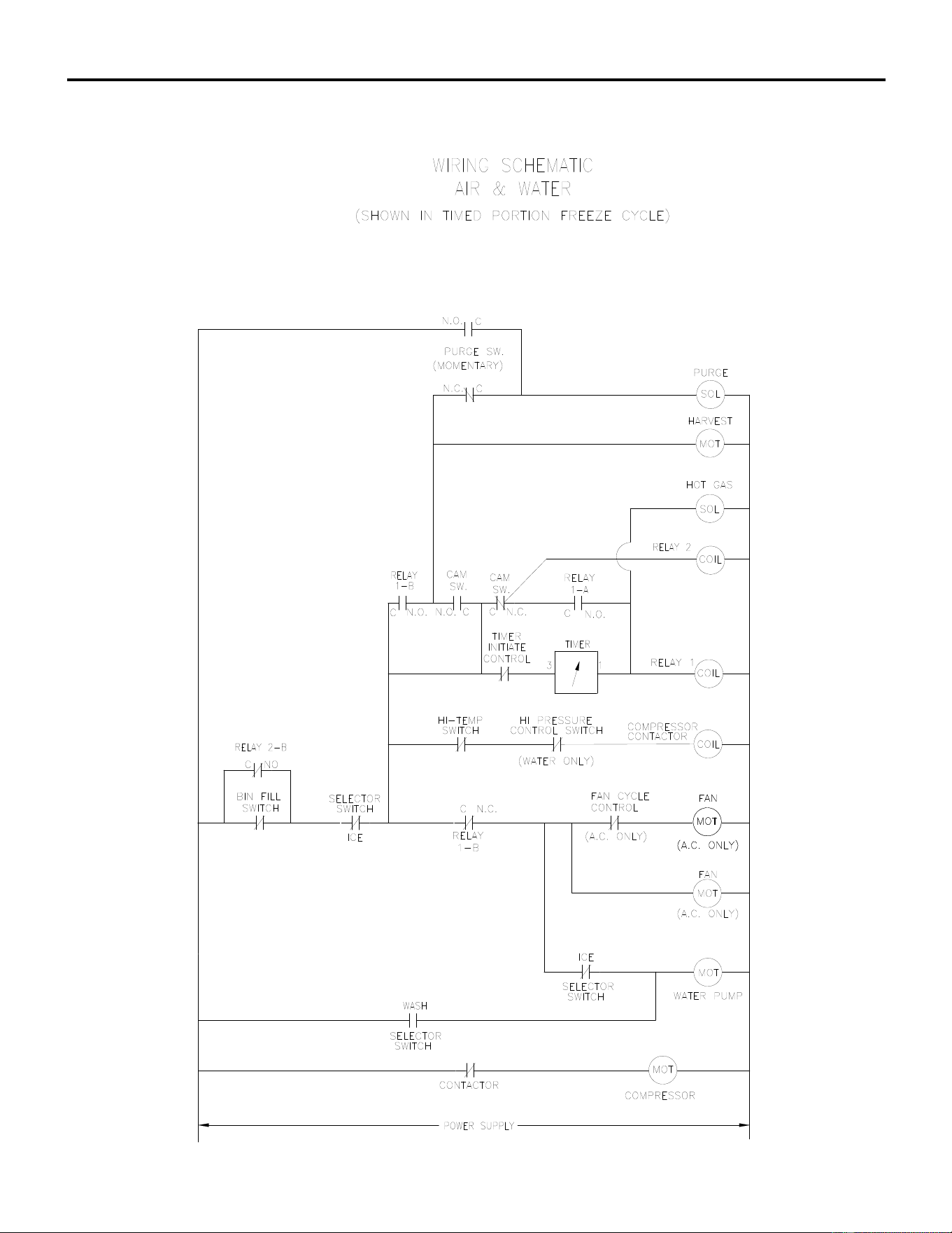
ICE Series Wiring Diagram
Page G100
ICE1006A5-W4/ICE0806A5-W5 Wiring Schematic
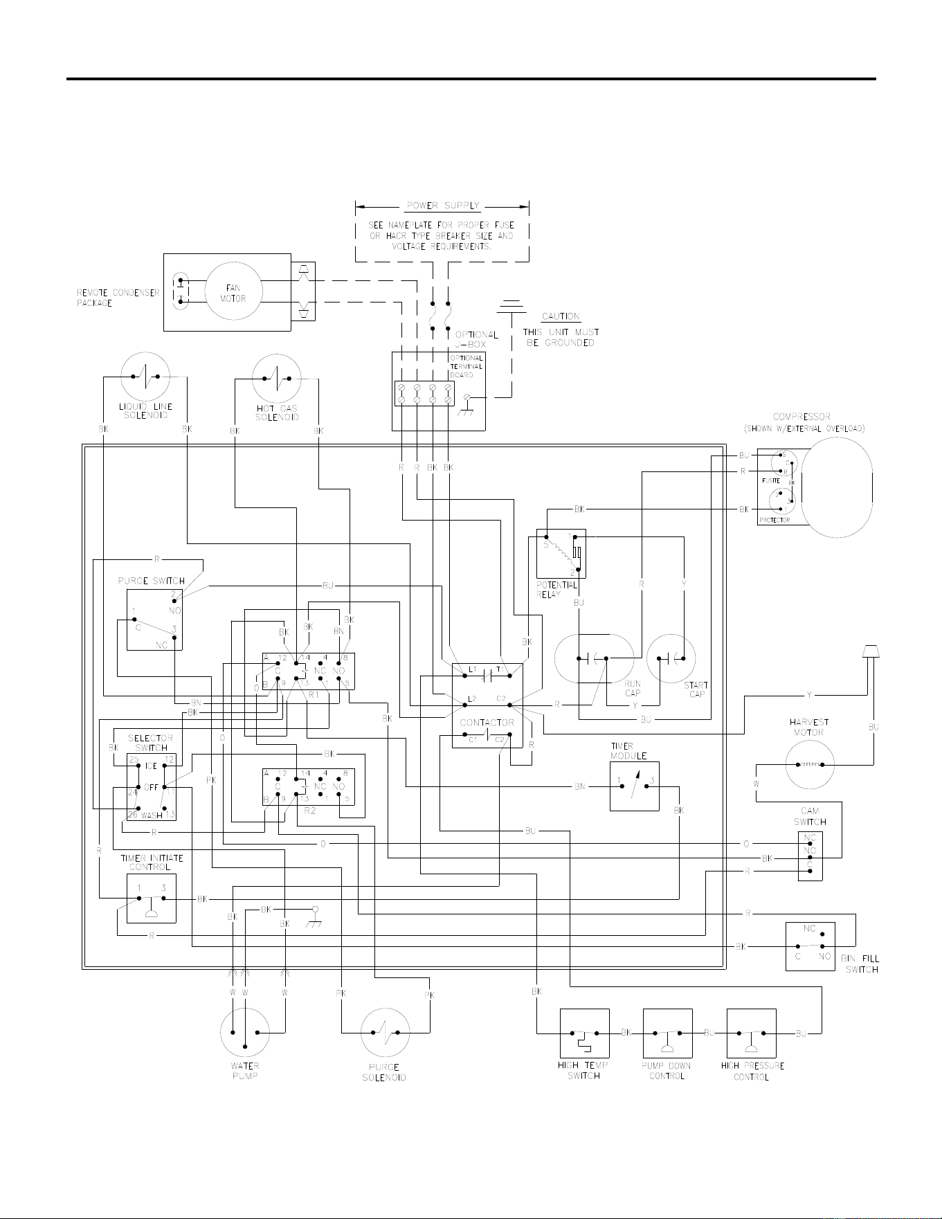
ICE Series Wiring Diagram
Page G101
ICE726R/ICE926R Wiring Diagram
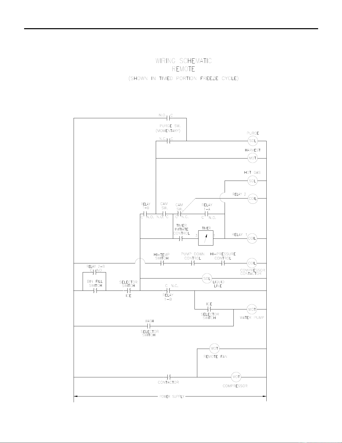
ICE Series Wiring Diagram
Page G102
ICE726R/ICE926R Wiring Schematic
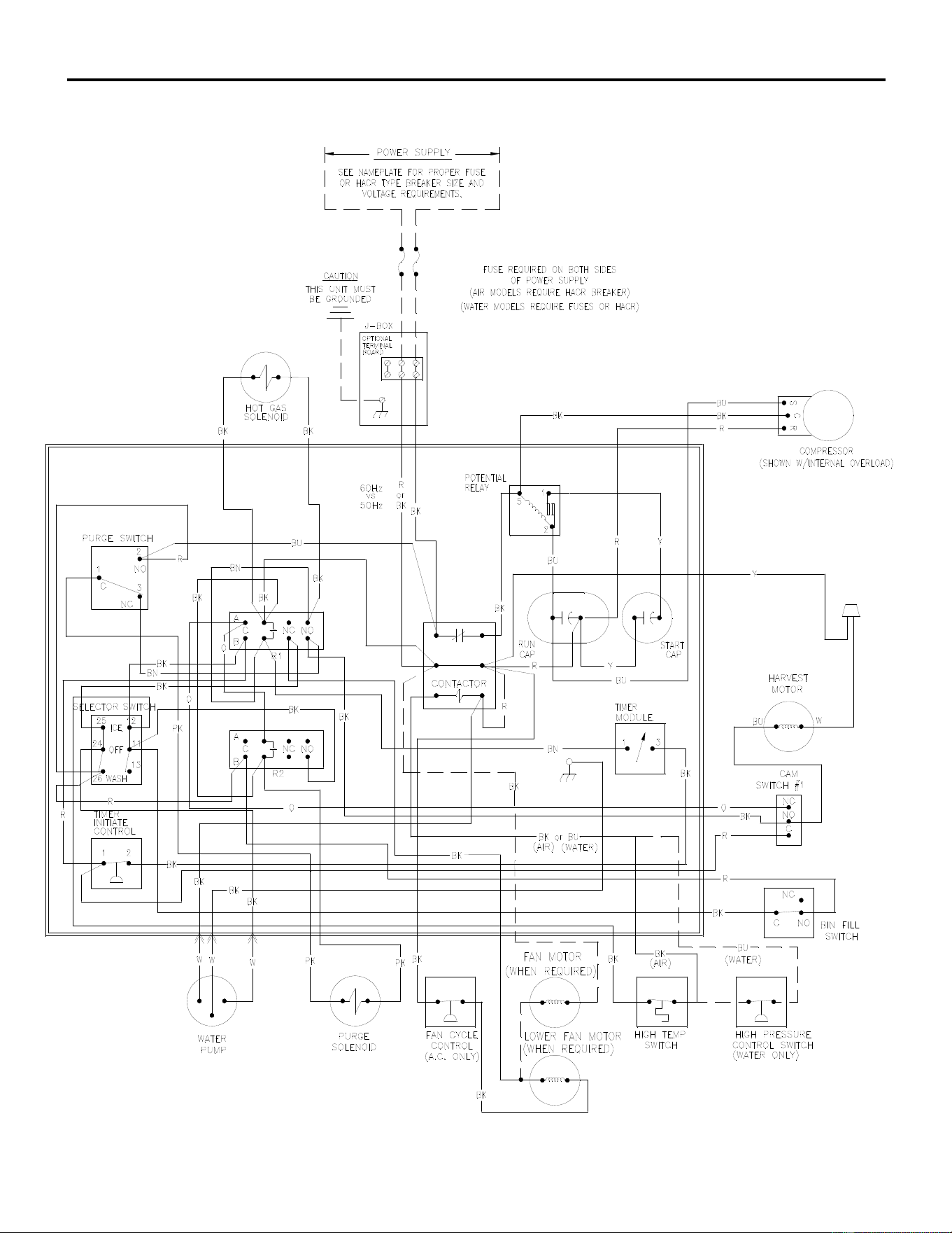
ICE Series Wiring Diagram
Page G103
ICE855A/ICE856A ICE1006A6/ICE1006W5 Wiring Diagram
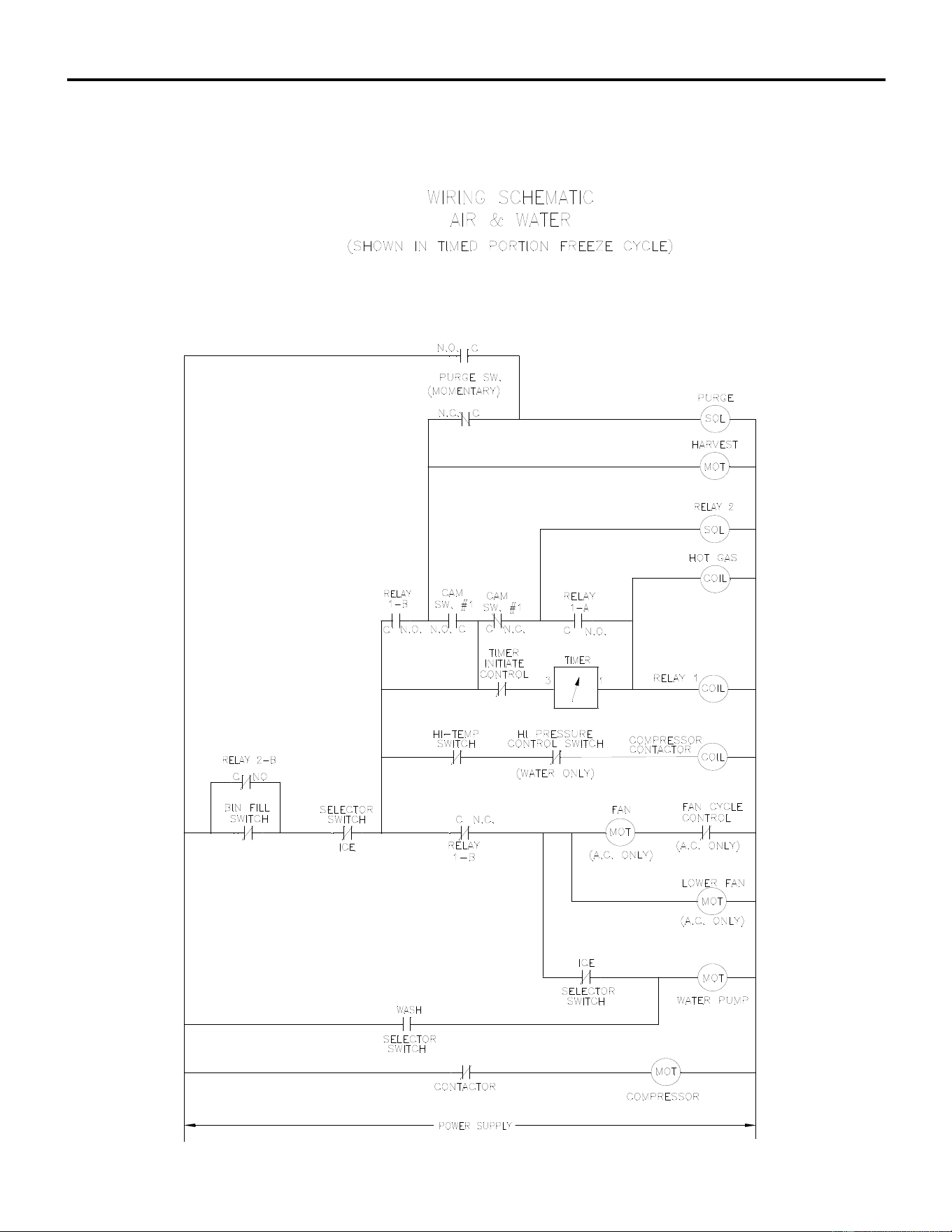
ICE Series Wiring Diagram
Page G104
ICE855A/ICE856A ICE1006A6/ICE1006W5 Wiring Schematic
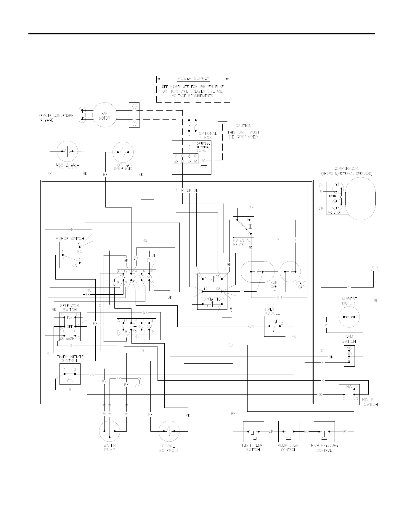
ICE Series Wiring Diagram
Page G105
ICE1006R6 Wiring Diagram
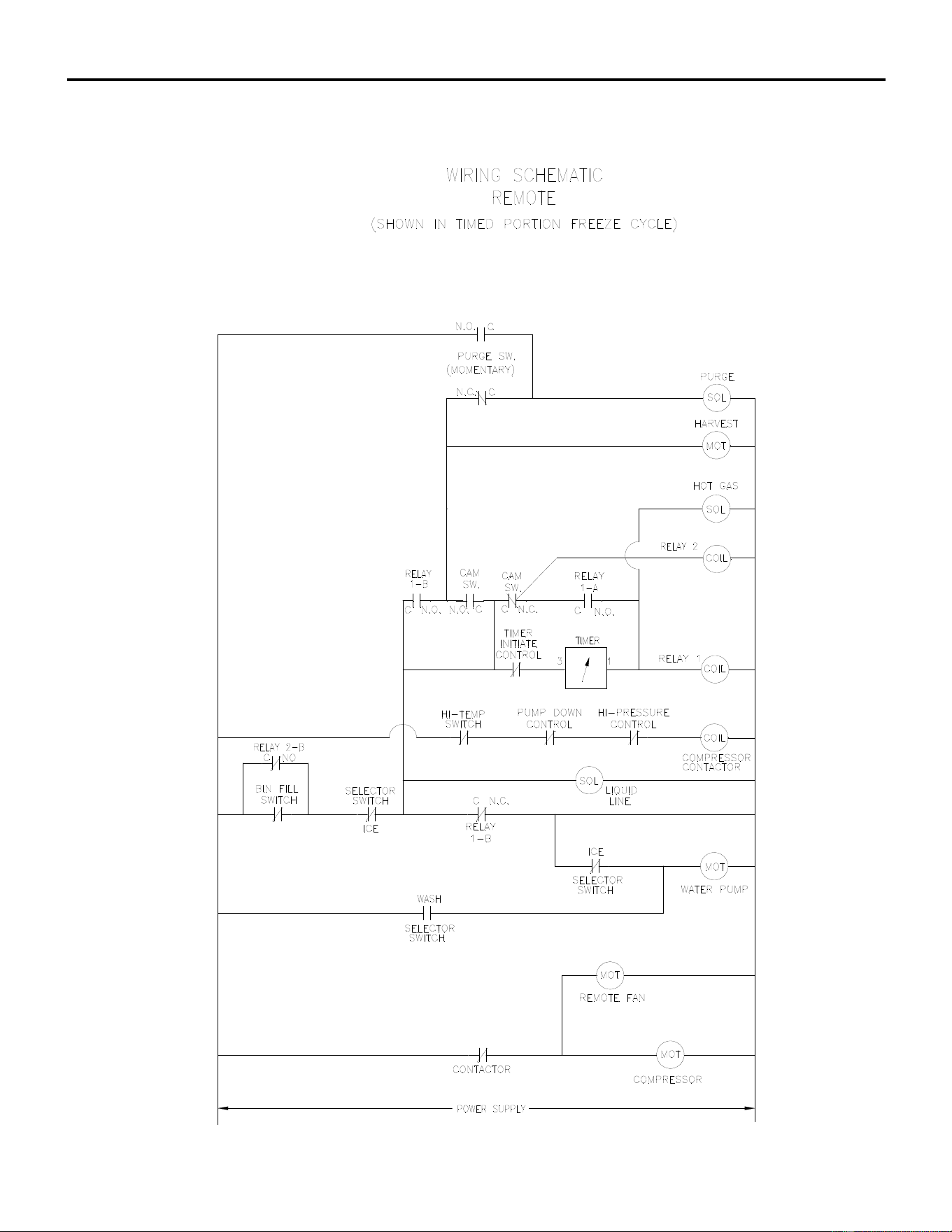
ICE Series Wiring Diagram
Page G106
ICE1006R6 Wiring Schematic
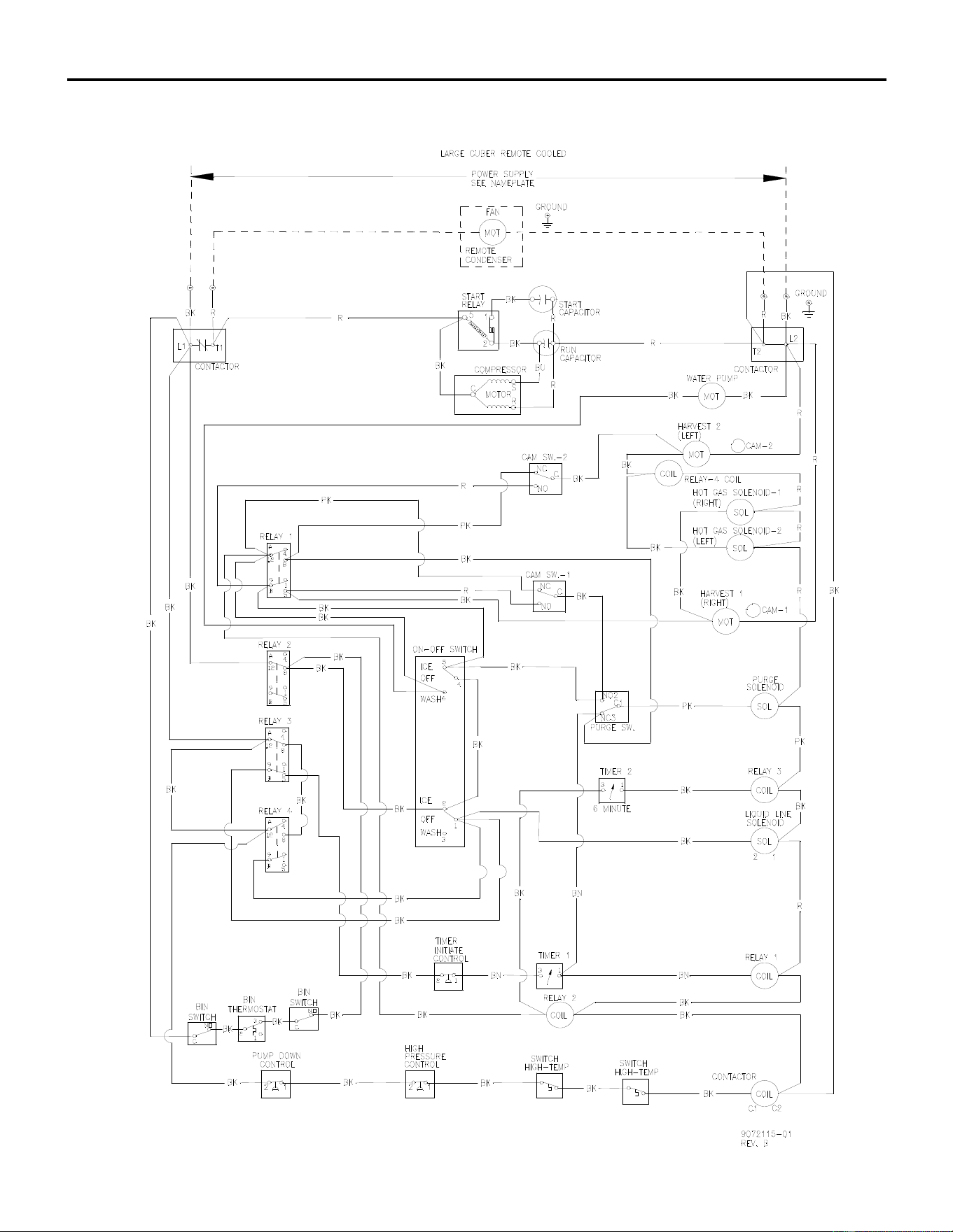
ICE Series Wiring Diagram
Page G107
ICE1506R5 Wiring Diagram
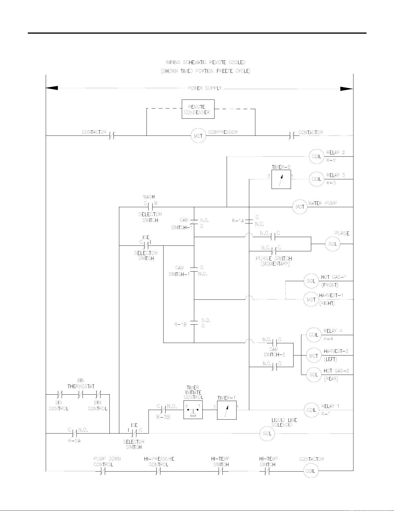
ICE Series Wiring Diagram
Page G108
ICE1506R5 Wiring Schematic
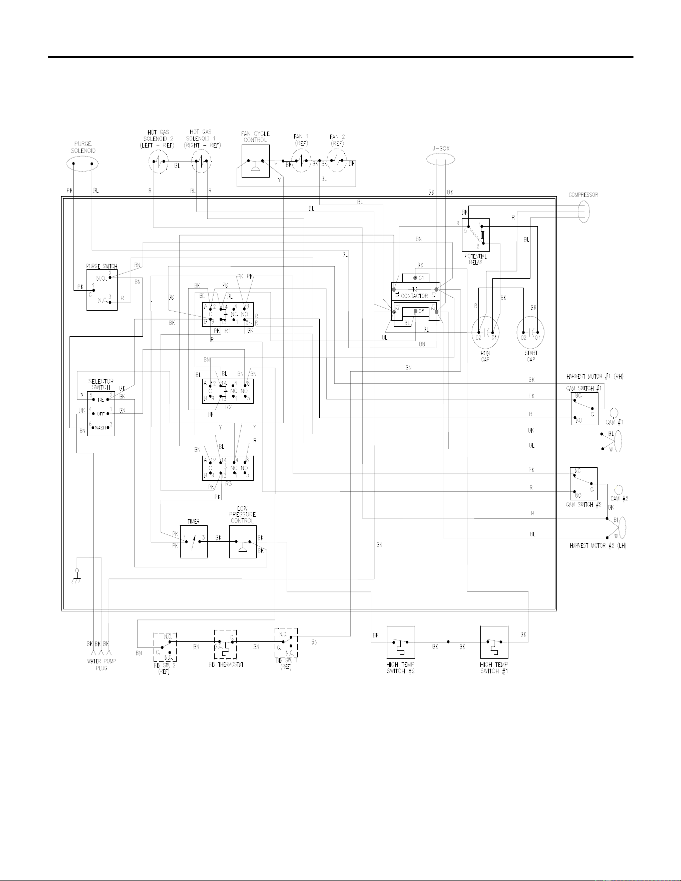
ICE Series Wiring Diagram
Page G109
ICE1506T Wiring Diagram
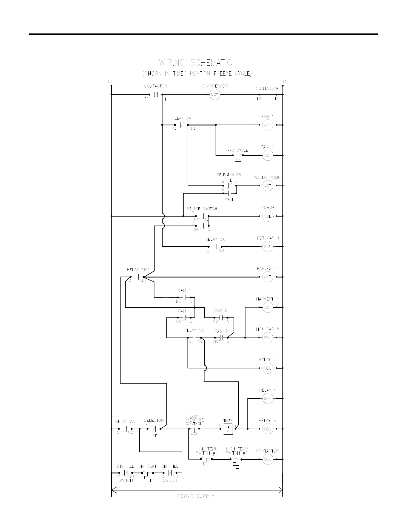
ICE Series Wiring Diagram
Page G110
ICE1506T Wiring Schematic
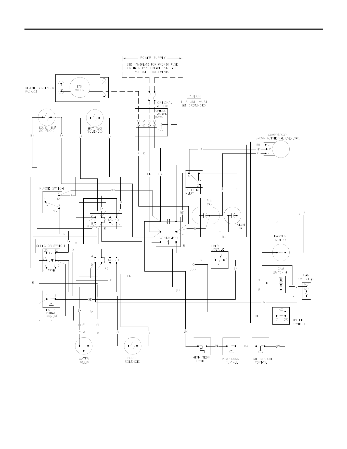
ICE Series Wiring Diagram
Page G111
ICE1006R Dual Cam Switch Wiring Diagram
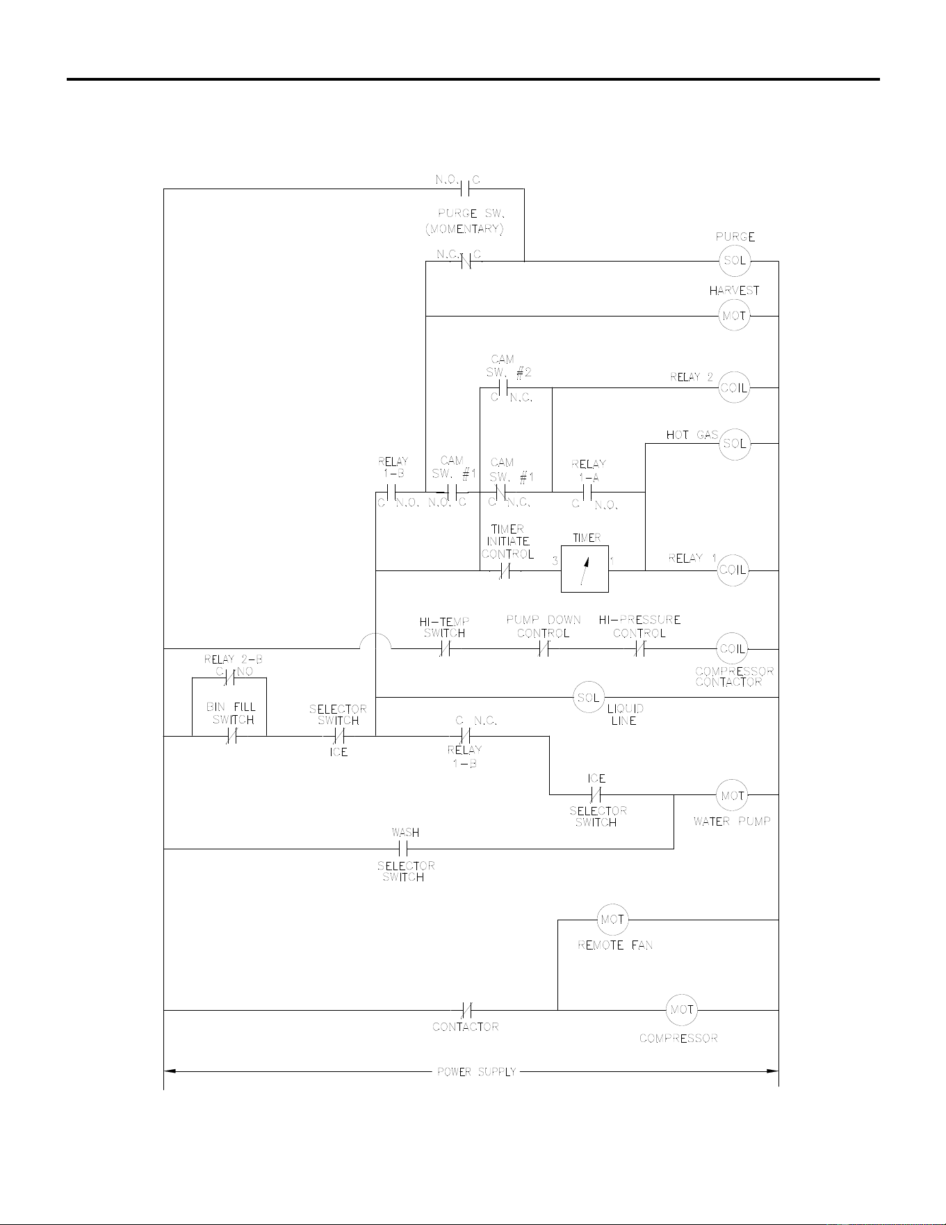
ICE Series Wiring Diagram
Page G112
ICE1006R Dual Cam Switch Wiring Schematic
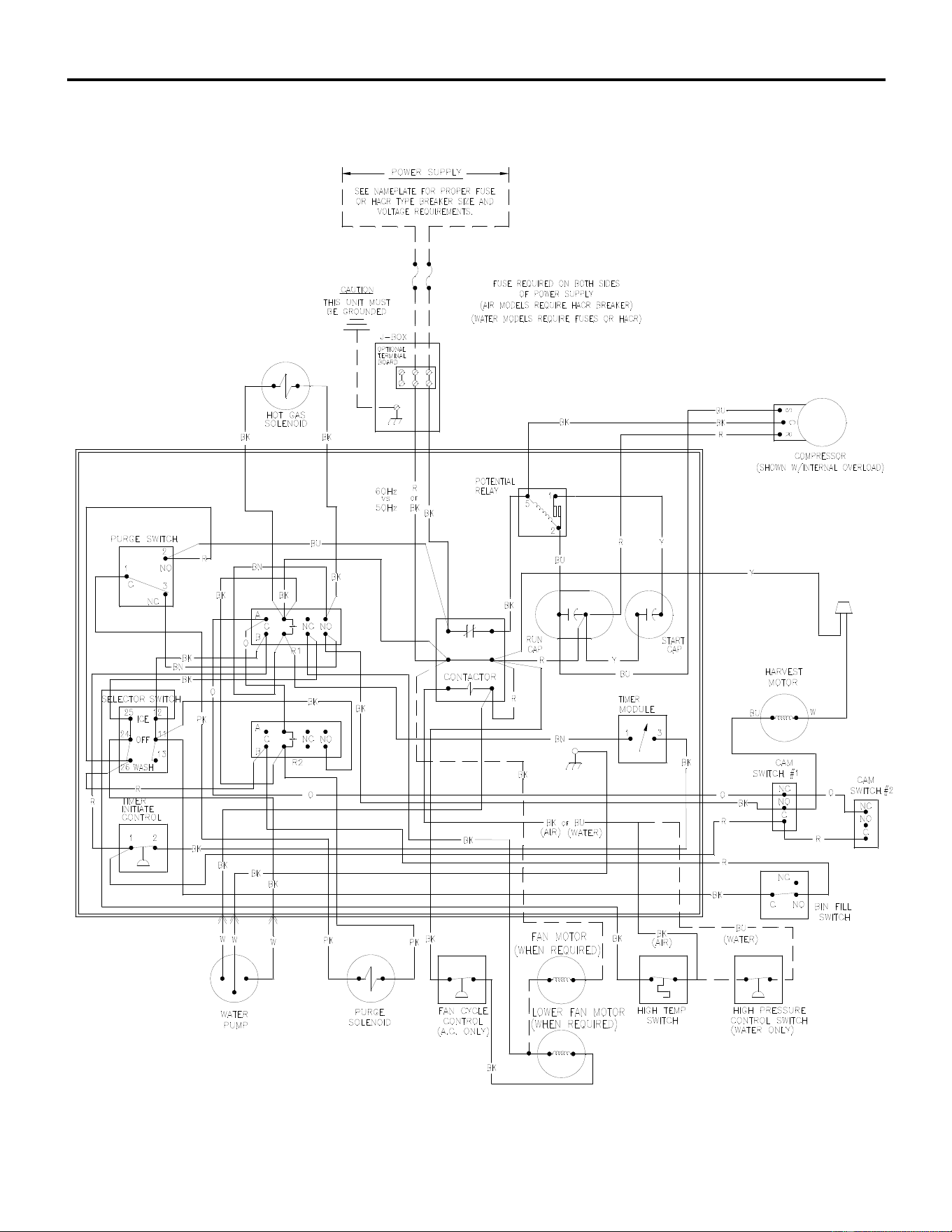
ICE Series Wiring Diagram
Page G113
ICE0806A/W 1006A/W Dual Cam Switch Wiring Diagram
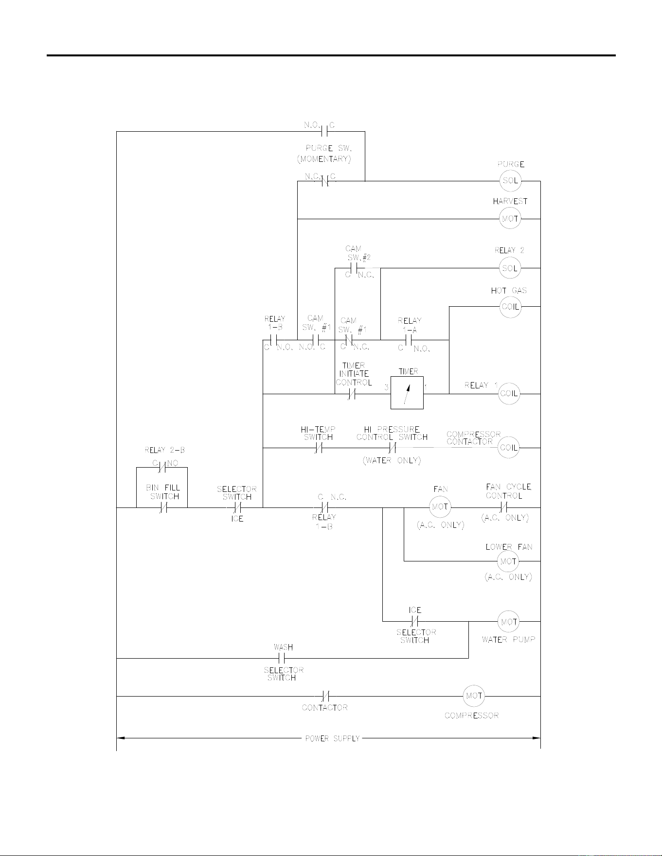
ICE Series Wiring Diagram
Page G114
ICE0806 A/W ICE1006A/W Dual Cam Switch Wiring Schematic

ICE Series Notes
Table of Contents
Table of Contents Page A1
General Information
How To Use This Manual Page A2
Model And Serial Number Format Page A3
Electrical And Mechanical Specifications Page A5-A8
Installation Guidelines Page A9
Electrical And Plumbing Requirements Page A10-A17
Remote Condenser Installation Page A18-A19
How The Machine Works Page A20
Undercounter Model Bin Removal Page A21-A22
Warranty Information Page A23-A24
Scheduled Maintenance
Maintenance Procedure Page B1
Cleaning and Sanitizing Instructions Page B1-B2
Winterizing Procedure Page B3
Cabinet Care Page B4
Troubleshooting Trees
How to Use The Troubleshooting Trees Page C1
Troubleshooting Trees Table Of Contents Page C2
Troubleshooting Trees Page C3-C18
Water System
Water Distribution And Components Page D1-D5
Refrigeration System
Refrigeration Cycle And Components Page E1
Harvest Cycle Page E5
Remote System Page E5-E6
Pump Down System Page E7
Refrigerant Specifications Page E8-E20
Electrical System
Control Circuit Page F1
Compressor And Start Components Page F1-F2
Untimed Freeze Cycle Page F3
Timed Freeze Cycle Page F4
Harvest Cycle Page F5-F9
Pump Down System Page F9
Wiring Diagrams Page G1

ICE Series Cuber Performance Data
Page H1 82215
24 Hour
Capacity Wires Max Min.
Voltage @ 90/70 Including Fuse Circuit Comp. **Refrigerant
Model Hz/Phase Lbs. Kg. BTUH Ground Size Amps RLA Type Oz. Grams
ICEU150*A1 115/60/1 117 53 3148 3 15 9.6 6.8 R404A 13 369
ICEU150*W1 115/60/1 166 75 3392 3 15 7.9 5.9 R404A 10 284
ICEU150*A2 115/60/1 117 53 3148 3 15 9.6 6.8 R404A 13 369
ICEU150*W2 115/60/1 166 75 3392 3 15 7.9 5.9 R404A 10 284
ICEU150*A3 115/60/1 112 51 3572 3 15 9.7 6.9 R404A 12 340
ICEU150*W3 115/60/1 155 70 3732 3 15 7.9 5.9 R404A 9 255
ICEU150*A4 115/60/1 112 51 3572 3 15 9.7 6.9 R404A 12 340
ICEU150*W4 115/60/1 155 70 3732 3 15 7.9 5.9 R404A 9 255
ICEU150*A5 115/60/1 130 59 3572 3 15 9.7 6.8 R404A 12 340
ICEU150*W5 115/60/1 140 64 3569 3 15 7.9 5.9 R404A 9 255
ICEU200*A1 115/60/1 157 71 4435 3 15 11.6 8.2 R404A 13 369
ICEU200*W1 115/60/1 183 83 4199 3 15 8.9 6.7 R404A 9 255
ICEU200*A2 115/60/1 157 71 4435 3 15 11.6 8.2 R404A 13 369
ICEU200*W2 115/60/1 183 83 4199 3 15 8.9 6.7 R404A 9 255
ICEU220*A1 115/60/1 175 80 4609 3 15 11.9 8.5 R404A 12 340
ICEU220*W1 115/60/1 220 100 4642 3 15 8.9 6.7 R404A 9 255
ICEU220*A2 115/60/1 175 80 4609 3 15 11.9 8.5 R404A 12 340
ICEU220*W2 115/60/1 220 100 4642 3 15 8.9 6.7 R404A 9 255
ICEU220*A3 115/60/1 175 79 4609 3 15 11.9 8.5 R404A 12 340
ICEU220*W3 115/60/1 193 88 4288 3 15 8.9 6.7 R404A 9 255
ICEU206*A1 230/60/1 162 74 4115 3 15 4.8 3.2 R-134a 14 397
ICEU206*W1 230/60/1 190 86 4009 3 15 4.0 2.9 R-134a 11 312
ICEU226*A1 230/60/1 168 76 4321 3 15 6.0 4.2 R404A 12 340
ICEU226*W1 230/60/1 192 87 4263 3 15 4.4 3.2 R404A 9 255
ICEU226*A2 230/60/1 168 76 4321 3 15 6.0 4.2 R404A 12 340
ICEU226*W2 230/60/1 192 87 4263 3 15 4.4 3.2 R404A 9 255
ICEU226*A3 230/60/1 168 76 4321 3 15 6.0 4.2 R404A 12 340
ICEU226*W3 230/60/1 192 87 4263 3 15 4.4 3.2 R404A 9 255
ICEU300A1 115/60/1 228 104 5928 3 15 13.1 8.8 R404A 16 454
ICEU300W1 115/60/1 296 135 6097 3 15 11.1 8.5 R404A 13 369
ICEU300A2 115/60/1 228 103 5928 3 15 13.1 8.8 R404A 16 454
ICEU300W2 115/60/1 296 135 6097 3 15 11.1 8.5 R404A 13 369
ICEU300A3 115/60/1 228 103 5928 3 15 13.1 8.8 R404A 16 454
ICEU300W3 115/60/1 296 135 6097 3 15 11.1 8.5 R404A 13 369
ICE0250*A2 115/60/1 244 111 6221 3 15 13.3 8.6 R404A 16 454
ICE0250*A-T2 115/60/1 244 111 6221 3 15 13.3 8.6 R404A 16 454
ICE0250*W2 115/60/1 284 129 6030 3 15 10.8 8.2 R404A 13 369
ICE0250*A3 115/60/1 244 111 6221 3 15 13.3 8.6 R404A 16 454
ICE0250*A-T3 115/60/1 244 111 6221 3 15 13.3 8.6 R404A 16 454
ICE0250*W3 115/60/1 284 129 6030 3 15 10.8 8.2 R404A 13 369
ICE0250*A4 115/60/1 253 115 6248 3 15 13.3 8.6 R404A 25 709
ICE0250*A-T4 115/60/1 244 111 6248 3 15 13.3 8.6 R404A 25 709
ICE0250*W4 115/60/1 275 125 5855 3 15 10.8 8.2 R404A 13 369
ICE0250*A5 115/60/1 253 115 6248 3 15 13.3 8.6 R404A 25 709
ICE0250*A6 115/60/1 263 115 6248 3 15 13.3 8.6 R404A 25 709
ICE0250*T5 115/60/1 244 111 6248 3 15 13.3 8.6 R404A 25 709
ICE0250*W5 115/60/1 275 125 5855 3 15 10.8 8.2 R404A 13 369
ICE0250*T6 115/60/1 244 111 5855 3 15 13.3 8.6 R404A 25 709
ICE0320*A1 115/60/1 214 97 5910 3 15 13.8 9.0 R404A 18 510
ICE0320*W1 115/60/1 312 142 6195 3 15 10.9 8.3 R404A 15 425
ICE0320*A2 115/60/1 214 97 5910 3 15 13.8 9.0 R404A 18 510
ICE0320*W2 115/60/1 312 142 6195 3 15 13.1 10.1 R404A 11 312
ICE0320*A3 115/60/1 214 97 5910 3 15 13.2 9.0 R404A 18 510
ICE0320*W3 115/60/1 312 142 6195 3 15 13.1 10.1 R404A 11 312
ICE0320*A4 115/60/1 249 113 6228 3 15 13.2 9.0 R404A 18 510
ICE0320*A5 115/60/1 249 113 6228 3 15 13.2 9.0 R404A 18 510

ICE Series Cuber Performance Data
Page H2 82215
24 Hour
Capacity Wires Max Min.
Voltage @ 90/70 Including Fuse Circuit Comp. **Refrigerant
Model Hz/Phase Lbs. Kg. BTUH Ground Size Amps RLA Type Oz. Grams
ICE0320*W4 115/60/1 308 140 6115 3 15 13.1 10.1 R404A 11 312
ICE0320*W5 115/60/1 308 140 6115 3 15 13.1 10.1 R404A 11 312
ICE0400*A1 115/60/1 366 166 8064 3 15 14.4 9.5 R404A 32 907
ICE0400*A-T1 115/60/1 368 167 8101 3 15 14.1 9.3 R404A 32 907
ICE0400*W1 115/60/1 449 204 8388 3 15 13.4 10.3 R404A 14 397
ICE0400*A2 115/60/1 366 166 8064 3 15 14.4 9.5 R404A 29 822
ICE0400*A-T2 115/60/1 368 167 8101 3 15 14.1 9.3 R404A 29 822
ICE0400*W2 115/60/1 449 204 8388 3 15 13.4 10.3 R404A 14 397
ICE0400*A3 115/60/1 368 167 7835 3 20 17.1 11.7 R404A 30 850
ICE0400*A-T3 115/60/1 357 162 7757 3 20 17.1 11.7 R404A 30 850
ICE0400*W3 115/60/1 407 185 7563 3 15 12.9 9.9 R404A 14 397
ICE0400*A4 115/60/1 368 167 7835 3 20 17.1 11.7 R404A 30 850
ICE0400*A-T4 115/60/1 357 162 7757 3 20 17.1 11.7 R404A 30 850
ICE0400*W4 115/60/1 407 185 7563 3 15 12.9 9.9 R404A 14 397
ICE0400*A5 115/60/1 368 167 7835 3 20 17.1 11.7 R404A 30 850
ICE0400*T5 115/60/1 357 162 7757 3 20 17.1 11.7 R404A 30 850
ICE0400*T6 115/60/1 357 162 7757 3 20 17.1 11.7 R404A 30 850
ICE0406*A1 208-230/60/1 323 147 7712 3 15 8.8 5.9 R404A 32 907
ICE0406*W1 208-230/60/1 381 173 7664 3 15 7.5 5.7 R404A 16 454
ICE0406*A2 208-230/60/1 323 147 7712 3 15 8.8 5.9 R404A 32 907
ICE0406*W2 208-230/60/1 381 173 7664 3 15 7.5 5.7 R404A 16 454
ICE0406*A3 208-230/60/1 385 175 7832 3 15 8.0 5.3 R404A 30 850
ICE0406*W3 208-230/60/1 439 200 7770 3 15 6.4 4.8 R404A 14 397
ICE0406*A4 208-230/60/1 358 162 7523 3 15 8.0 5.3 R404A 30 850
ICE0406*A5 208-230/60/1 358 162 7523 3 15 8.0 5.3 R404A 30 850
ICE0406*W4 208-230/60/1 439 200 7770 3 15 6.4 4.8 R404A 14 397
ICE0500*A1 115/60/1 461 210 10843 3 20 24.8 18.5 R404A 37 1049
ICE0500*A-T1 115/60/1 455 207 10736 3 20 24.8 18.5 R404A 37 1049
ICE0500*W1 115/60/1 499 227 10242 3 20 13.6 10.5 R404A 15 425
ICE0500*R1 115/60/1 407 199 10881 3 20 18.7 12.3 R404A 160 4536
ICE0500*A2 115/60/1 461 210 10843 3 20 19.9 13.9 R404A 22 624
ICE0500*A-T2 115/60/1 455 207 10736 3 20 19.9 13.9 R404A 22 624
ICE0500*W2 115/60/1 499 227 10242 3 20 13.6 10.5 R404A 15 425
ICE0500*R2 115/60/1 407 199 10881 3 20 18.7 12.3 R404A 160 4536
ICE0500*A3 115/60/1 458 208 9990 3 20 19.1 13.3 R404A 25 709
ICE0500*A-T3 115/60/1 470 214 9982 3 20 19.1 13.3 R404A 25 709
ICE0500*W3 115/60/1 513 233 9777 3 20 14.3 11.0 R404A 15 425
ICE0500*R3 115/60/1 446 203 11357 3 20 18.7 12.3 R404A 132 3742
ICE0500*R4 115/60/1 455 207 10278 3 20 14.9 9.3 R404A 132 3742
ICE0500*A4 115/60/1 458 208 9990 3 20 19.1 13.3 R404A 25 709
ICE0500*A-T4 115/60/1 470 214 9982 3 20 19.1 13.3 R404A 25 709
ICE0500*A-T5 115/60/1 470 214 9982 3 20 19.1 13.3 R404A 25 709
ICE0500*A5 115/60/1
448 203 9835
3
20
19.0 13.3 R404A
25 709
ICE0500*T6 115/60/1 448 203 9790 3 20 19.0 13.3 R404A 25 709
ICE0500*W4 115/60/1 513 233 9777 3 20 14.3 11.0 R404A 15 425
ICE0500*R5 115/60/1 455 207 10278 3 20 14.9 9.3 R404A 132 3742
ICE0520*A1 115/60/1 353 160 8441 3 20 18.3 12.3 R404A 32 907
ICE0520*W1 115/60/1 442 201 8356 3 15 13.5 10.4 R404A 14 397
ICE0520*A2 115/60/1 353 160 8441 3 20 15.4 10.6 R404A 20 567
ICE0520*W2 115/60/1 442 201 8356 3 15 13.5 10.4 R404A 14 397
ICE0520*A3 115/60/1 370 168 7753 3 20 16.0 11.1 R404A 21 595
ICE0520*W3 115/60/1 442 201 7852 3 15 11.8 9.0 R404A 12 340
ICE0520*A4 115/60/1 370 168 7753 3 20 16.0 11.1 R404A 21 595
ICE0520*A5 115/60/1 370 168 7753 3 20 16.0 11.1 R404A 21 595
ICE0520*A6 115/60/1 370 168 7753 3 20 16.0 11.1 R404A 21 595

ICE Series Cuber Performance Data
Page H3 82215
24 Hour
Capacity Wires Max Min.
Voltage @ 90/70 Including Fuse Circuit Comp. **Refrigerant
Model Hz/Phase Lbs. Kg. BTUH Ground Size Amps RLA Type Oz. Grams
ICE0520*W4 115/60/1 442 201 7852 3 15 11.8 9.0 R404A 12 340
ICE0520*W5 115/60/1 442 201 7852 3 15 11.8 9.0 R404A 12 340
ICE0606*A1 208-230/60/1 525 239 11538 3 15 12.4 8.8 R404A 36 1021
ICE0606*A-T1 208-230/60/1 510 232 11293 3 15 13.3 9.5 R404A 36 1021
ICE0606*W1 208-230/60/1 590 268 11473 3 15 9.5 7.3 R404A 18 510
ICE0606*R1 208-230/60/1 544 247 12269 3 15 13.0 8.7 R404A 160 4536
ICE0606*A2 208-230/60/1 525 239 11538 3 15 12.0 8.5 R404A 24 1021
ICE0606*A-T2 208-230/60/1 510 232 11293 3 15 11.7 8.2 R404A 24 1021
ICE0606*W2 208-230/60/1 590 268 11473 3 15 9.5 7.3 R404A 18 510
ICE0606*R2 208-230/60/1 544 247 12269 3 15 13.0 8.7 R404A 160 4536
ICE0606*R3 208-230/60/1 543 247 12132 3 15 13.0 8.7 R404A 132 3742
ICE0606*A3 208-230/60/1 506 230 10566 3 15 11.5 7.9 R404A 24 680
ICE0606*A-T3 208-230/60/1 505 230 10566 3 15 10.4 7.0 R404A 26 737
ICE0606*W3 208-230/60/1 502 228 10767 3 15 8.7 6.6 R404A 17 482
ICE0606*R4 208-230/60/1 576 262 10850 3 15 12.9 8.6 R404A 132 3742
ICE0606*A4 208-230/60/1 506 230 10566 3 15 11.5 7.9 R404A 24 680
ICE0606*A-T4 208-230/60/1 505 230 10566 3 15 10.4 7.0 R404A 26 737
ICE0606*W4 208-230/60/1 502 228 10767 3 15 8.7 6.6 R404A 17 482
ICE0606*R5 208-230/60/1 576 262 10850 3 15 12.9 8.6 R404A 132 3742
ICE0606*W5 208-230/60/1 550 249 10767 3 15 10.0 6.6 R404A 17 482
ICE0606*A5 208-230/60/1 530 240 10556 3 15 10.7 7.9 R404A 24 680
ICE0606*T6 208-230/60/1 530 240 10884 3 15 10.7 7 R404A 26 737
ICE0606*R6 208-230/60/1 550 249 10767 3 15 11.1 8.6 R404A 132 3742
ICE0726R 208-230/60/1 700 318 15250 3 20 14.0 9.8 R404A 176 4990
ICE0806*A1 208-230/60/1 698 317 15003 3 20 13.0 9.2 R404A 41 1163
ICE0806*W1 208-230/60/1 840 382 14458 3 20 9.8 7.4 R404A 29 823
ICE0806*R1 208-230/60/1 762 346 15168 3 20 12.3 8.1 R404A 240 6804
ICE0806*A2 208-230/60/1 698 317 15003 3 20 13.0 9.2 R404A 27 765
ICE0806*W2 208-230/60/1 840 382 14458 3 20 9.8 7.4 R404A 24 680
ICE0806*R2 208-230/60/1 762 346 15168 3 20 12.3 8.1 R404A 240 6804
ICE0806*A2 208-230/60/1 698 317 15003 3 20 13.0 9.2 R404A 27 765
ICE0806*W2 208-230/60/1 840 382 14458 3 20 9.8 7.4 R404A 24 680
ICE0806*R3 208-230/60/1 826 375 16371 3 20 12.3 8.1 R404A 176 4990
ICE0806*A3 208-230/60/1 698 317 13806 3 20 13.2 9.2 R404A 31 879
ICE0806*W3 208-230/60/1 840 382 14355 3 20 9.8 7.4 R404A 28 794
ICE0806*R4 208-230/60/1 826 375 15205 3 20 14.7 8.1 R404A 176 4990
ICE0806*A4 208-230/60/1 698 317 13806 3 20 13.2 9.2 R404A 31 879
ICE0806*W4 208-230/60/1 840 382 14355 3 20 9.8 7.4 R404A 28 794
ICE0806*A5 208-230/60/1 650 295 13806 3 20 13.2 7.2 R404A 31 879
ICE0806*W5 208-230/60/1 784 356 14355 3 20 9.8 7.4 R404A 28 794
ICE0806*R5 208-230/60/1 768 348 15205 3 20 14.7 10.8 R404A 176 4990
ICE0926R 208-230/60/1 780 354 17200 3 20 16.2 11.6 R404A 176 4990
ICE1006*A1 208-230/60/1 811 369 16239 3 20 13.8 9.0 R404A 50 1418
ICE1006*W1 208-230/60/1 941 428 15986 3 20 9.0 6.8 R404A 32 908
ICE1006*R1 208-230/60/1 905 411 18149 3 20 13.8 9.3 R404A 240 6804
ICE1006*A2 208-230/60/1 811 369 16239 3 20 13.8 9.0 R404A 34 964
ICE1006*W2 208-230/60/1 941 428 15986 3 20 9.0 6.8 R404A 24 680
ICE1006*R2 208-230/60/1 905 411 18149 3 20 13.8 9.3 R404A 240 6804
ICE1006*R3 208-230/60/1 921 419 18377 3 20 13.8 9.3 R404A 176 4990
ICE1006*A3 208-230/60/1 780 355 16024 3 20 14.2 9.0 R404A 34 964
ICE1006*W3 208-230/60/1 856 389 15355 3 20 12.8 9.8 R404A 29 822
ICE1006*R4 208-230/60/1 843 383 17161 3 20 13.8 9.3 R404A 176 4990
ICE1006*A4 208-230/60/1 780 355 16024 3 20 14.2 9.0 R404A 34 964
ICE1006*W4 208-230/60/1 856 389 15355 3 20 12.8 9.8 R404A 29 822
ICE1006*W5 208-230/60/1 856 389 15355 3 20 12.8 9.8 R404A 33 936
ICE1006*W6 208-230/60/1 856 389 15355 3 20 12.8 9.8 R404A 33 936

ICE Series Cuber Performance Data
Page H4 82215
24 Hour
Capacity Wires Max Min.
Voltage @ 90/70 Including Fuse Circuit Comp. **Refrigerant
Model Hz/Phase Lbs. Kg. BTUH Ground Size Amps RLA Type Oz. Grams
ICE1006*A5 208-230/60/1 760 345 16024 3 20 14.2 9.0 R404A 34 964
ICE1006*A6 208-230/60/1 793 360 16024 3 20 14.2 9.0 R404A 38 1077
ICE1006*A7 208-230/60/1 793 360 16024 3 20 14.2 9.0 R404A 38 1077
ICE1006*R5 208-230/60/1 843 383 17161 3 20 13.8 9.3 R404A 176 4990
ICE1006*R6 208-230/60/1 843 383 17161 3 20 13.8 9.3 R404A 176 4990
ICE1006*R7 208-230/60/1 843 383 17161 3 20 13.8 9.3 R404A 176 4990
ICE1007*W1 208-230/60/3 906 412 16487 4 15 7.1 5.3 R404A 32 908
ICE1007*R1 208-230/60/3 844 384 17653 4 15 10.8 6.9 R404A 240 6804
ICE1007*A2 208-230/60/3 767 349 15614 4 15 11.8 7.4 R404A 34 964
ICE1007*W2 208-230/60/3 906 412 16487 4 15 7.1 5.3 R404A 24 680
ICE1007*R2 208-230/60/3 844 384 17653 4 15 10.8 6.9 R404A 240 6804
ICE1007*R3 208-230/60/3 844 384 17653 4 15 10.8 6.9 R404A 176 4990
ICE1007*A3 208-230/60/3 767 349 15490 4 15 12.2 7.4 R404A 34 964
ICE1007*W3 208-230/60/3 906 412 14996 4 15 7.1 5.3 R404A 29 822
ICE1007*R4 208-230/60/3 844 384 15317 4 15 10.8 6.9 R404A 176 4990
ICE1007*A4 208-230/60/3 767 349 15490 4 15 12.2 7.4 R404A 34 964
ICE1007*W4 208-230/60/3 935 425 14996 4 15 7.1 5.3 R404A 29 822
ICE1007*A5 208-230/60/3 767 349 15490 4 15 12.2 7.4 R404A 34 964
ICE1007*R4 208-230/60/3 781 354 15317 4 15 10.8 6.9 R404A 176 4990
ICE1007*R5 208-230/60/3 781 354 15317 4 15 10.8 6.9 R404A 176 4990
ICE1007*A6 208-230/60/3 800 363 15490 4 15 12.2 7.4 R404A 34 964
ICE1406*A1 208-230/60/1 1122 510 22590 3 30 20.2 13.8 R404A 108 3062
ICE1406*W1 208-230/60/1 1187 540 22529 3 20 15.6 11.7 R404A 28 794
ICE1406*R1 208-230/60/1 1134 515 23085 3 25 23.3 16.5 R404A 240 6804
ICE1406*A2 208-230/60/1 1122 510 22590 3 30 20.2 13.8 R404A 104 2948
ICE1406*W2 208-230/60/1 1187 540 22529 3 20 15.6 11.7 R404A 25 709
ICE1406*R2 208-230/60/1 1134 515 23085 3 25 23.3 16.5 R404A 240 6804
ICE1406*A3 208-230/60/1 1109 504 21957 3 30 26.1 17.9 R404A 60 1701
ICE1406*W3 208-230/60/1 1239 563 21994 3 20 17.8 13.5 R404A 30 851
ICE1406*R3 208-230/60/1 1150 523 22126 3 30 22.2 15.7 R404A 240 6804
ICE1406*A4 208-230/60/1 1109 504 21957 3 30 26.1 17.9 R404A 60 1701
ICE1406*W4 208-230/60/1 1239 563 21994 3 20 17.8 13.5 R404A 30 851
ICE1406*R4 208-230/60/1 1150 523 22126 3 30 22.2 15.7 R404A 240 6804
ICE1406*A5 208-230/60/1 1109 504 21957 3 30 26.1 17.9 R404A 60 1701
ICE1406*A6 208-230/60/1 1136 515 22069 3 30 26.1 17.9 R404A 60 1701
ICE1406*W5 208-230/60/1 1239 563 21994 3 20 17.8 13.5 R404A 30 850
ICE1406*R5 208-230/60/1 1150 523 22126 3 30 22.2 15.7 R404A 240 6804
ICE1407*A1 208-230/60/3 989 450 19765 4 25 15.1 9.7 R404A 108 3062
ICE1407*W1 208-230/60/3 1093 497 19809 4 20 9.8 7.1 R404A 28 794
ICE1407*R1 208-230/60/3 956 435 20173 4 25 14.0 9.1 R404A 240 6804
ICE1407*A2 208-230/60/3 989 450 19765 4 25 15.1 9.7 R404A 104 2948
ICE1407*W2 208-230/60/3 1093 497 19809 4 20 9.8 7.1 R404A 25 709
ICE1407*R2 208-230/60/3 956 435 20173 4 25 14.0 9.1 R404A 240 6804
ICE1407*A3 208-230/60/3 1131 514 21761 4 20 16.0 9.8 R404A 60 1701
ICE1407*W3 208-230/60/3 1270 577 22308 4 20 10.7 7.8 R404A 30 851
ICE1407*R3 208-230/60/3 1195 543 22547 4 20 14.7 9.8 R404A 240 6804
ICE1407*A4 208-230/60/3 1131 514 21761 4 20 16.0 9.8 R404A 60 1701
ICE1407*W4 208-230/60/3 1270 577 22308 4 20 10.7 7.8 R404A 30 851
ICE1407*R4 208-230/60/3 1195 543 22547 4 20 14.7 9.8 R404A 240 6804
ICE1407*A5 208-230/60/3 1131 514 21761 4 20 16.0 9.8 R404A 60 1701
ICE1407*W5 208-230/60/3 1270 577 22308 4 20 10.7 7.8 R404A 30 850
ICE1407*R5 208-230/60/3 1195 543 22547 4 20 14.7 9.7 R404A 240 6804

ICE Series Cuber Performance Data
Page H5 82215
24 Hour
Capacity Wires Max Min.
Voltage @ 90/70 Including Fuse Circuit Comp. **Refrigerant
Model Hz/Phase Lbs. Kg. BTUH Ground Size Amps RLA Type Oz. Grams
ICE1506*R 208-230/60/1 1202 559 24337 3 30 27.4 19.8 R404A 240 6804
ICE1506*R2 208-230/60/1 1207 549 22999 3 30 24.5 17.5 R404A 240 6804
ICE1506*R3 208-230/60/1 1207 549 22999 3 30 24.5 17.5 R404A 240 6804
ICE1506*R4 208-230/60/1 1216 553 22491 3 30 24.5 17.5 R404A 240 6804
ICE1506*R5 208-230/60/1 1216 553 22491 3 30 24.5 17.5 R404A 240 6804
ICE1606*R1 208-230/60/1 1240 564 24343 3 30 25.8 18.6 R404A 240 6804
ICE1806*W1 208-230/60/1 1461 664 25663 3 30 17.0 12.9 R404A 42 1191
ICE1806*R1 208-230/60/1 1468 667 27152 3 30 22.3 15.7 R404A 400 11340
ICE1806*W2 208-230/60/1 1461 664 25663 3 30 17.0 12.9 R404A 35 992
ICE1806*R2 208-230/60/1 1468 667 27152 3 30 22.3 15.7 R404A 400 11340
ICE1806*W3 208-230/60/1 1628 740 27687 3 30 22.0 16.9 R404A 37 1049
ICE1806*R3 208-230/60/1 1461 664 28110 3 30 27.7 20.1 R404A 272 7711
ICE1806*W4 208-230/60/1 1628 740 27687 3 30 22.0 16.9 R404A 37 1049
ICE1806*R4 208-230/60/1 1461 664 28110 3 30 27.7 20.1 R404A 272 7711
ICE1806*W5 208-230/60/1 1628 740 27687 3 30 22.0 16.9 R404A 44 1247
ICE1806*R5 208-230/60/1 1461 664 28110 3 30 27.7 20.1 R404A 272 7711
ICE1807*W1 208-230/60/3 1556 707 27146 4 15 10.7 7.8 R404A 42 1191
ICE1807*R1 208-230/60/3 1491 678 27966 4 15 15.5 10.3 R404A 400 11340
ICE1807*W2 208-230/60/3 1556 707 27146 4 15 10.7 7.8 R404A 42 1191
ICE1807*R2 208-230/60/3 1491 678 27966 4 15 15.5 10.3 R404A 400 11340
ICE1807*W3 208-230/60/3 1603 729 27560 4 15 12.3 9.1 R404A 37 1049
ICE1807*R3 208-230/60/3 1444 656 27514 4 20 17.1 11.6 R404A 272 7711
ICE1807*W4 208-230/60/3 1603 729 27560 4 15 12.3 9.1 R404A 37 1049
ICE1807*R4 208-230/60/3 1444 656 27514 4 20 17.1 11.6 R404A 272 7711
ICE1807*W5 208-230/60/3 1603 729 27560 4 15 12.3 9.1 R404A 37 1049
ICE1807*R5 208-230/60/3 1444 656 27514 4 20 17.1 11.6 R404A 272 7711
ICE1807*W5 208-230/60/3 1603 729 27560 4 15 12.3 9.1 R404A 37 1049
ICE1807*R5 208-230/60/3 1444 656 27514 4 20 17.1 11.6 R404A 272 7711
ICE2106*W1 208-230/60/1 1855 843 33333 3 30 28.5 22.1 R404A 50 1418
ICE2106*R1 208-230/60/1 1723 783 35369 3 50 43.1 31.0 R404A 400 11340
ICE2106*W2 208-230/60/1 1855 843 33333 3 30 25.3 19.5 R404A 37 1049
ICE2106*R2 208-230/60/1 1723 783 35369 3 50 33.7 23.5 R404A 400 11340
ICE2106*W3 208-230/60/1 1692 769 29406 3 30 22.3 17.1 R404A 44 1247
ICE2106*R3 208-230/60/1 1561 710 30325 3 30 26.9 18.1 R404A 272 7711
ICE2106*W4 208-230/60/1 1692 769 29406 3 30 22.3 17.1 R404A 44 1247
ICE2106*R4 208-230/60/1 1561 710 30325 3 30 26.9 18.1 R404A 272 7711
ICE2106*W5 208-230/60/1 1650 750 29091 3 30 22.3 17.1 R404A 44 1274
ICE2106*R5 208-230/60/1 1561 710 30034 3 30 26.9 18.1 R404A 272 7711
ICE2107*W1 208-230/60/3 1853 842 32928 4 20 13.9 10.4 R404A 50 1418
ICE2107*R1 208-230/60/3 1737 790 34714 4 25 22.3 14.4 R404A 400 11340
ICE2107*W2 208-230/60/3 1853 842 32928 4 20 16.6 12.6 R404A 37 1049
ICE2107*R2 208-230/60/3 1737 790 34714 4 25 23.2 15.1 R404A 400 11340
ICE2107*W3 208-230/60/3 1650 750 28676 4 30 13.5 10.1 R404A 44 1247
ICE2107*R3 208-230/60/3 1525 693 29342 4 25 21.2 13.5 R404A 272 7711
ICE2107*W4 208-230/60/3 1650 750 28676 4 30 13.5 10.1 R404A 44 1247
ICE2107*R4 208-230/60/3 1525 693 29342 4 25 21.2 13.5 R404A 272 7711
ICE2107*W5 208-230/60/3 1650 750 28369 4 30 13.5 10.1 R404A 44 1247
ICE2107*R5 208-230/60/3 1525 693 29342 4 25 21.2 13.5 R404A 272 7711

ICE Series Cuber Performance Data
Page H6 82215
24 Hour
Capacity Wires Max Min.
Voltage @ 90°/70° Including Fuse Circuit Comp. **Refrigerant
Model Hz/Phase Lbs. Kg. BTUH Ground Size Amps RLA Type Oz. Grams
ICEU205*A1 230/50/1 145 66 3842 3 15 6.0 4.1 R-134a 14 397
ICEU205*W1 230/50/1 175 80 3768 3 15 5.6 4.2 R-134a 11 312
ICEU205*A2 230/50/1 145 66 3842 3 15 6.0 4.1 R-134a 14 397
ICEU205*W2 230/50/1 175 80 3768 3 15 5.6 4.2 R-134a 11 312
ICEU225*A1 230/50/1 143 65 3774 3 15 4.9 3.3 R404A 12 340
ICEU225*W1 230/50/1 174 79 3780 3 15 4.1 3.0 R404A 9 256
ICEU225*A2 230/50/1 143 65 3774 3 15 4.9 3.3 R404A 12 340
ICEU225*W2 230/50/1 174 79 3780 3 15 4.1 3.0 R404A 9 256
ICEU225*A3 230/50/1 143 65 3774 3 16 4.9 3.3 R404A 12 340
ICEU225*W3 230/50/1 174 79 3780 3 16 4.1 3.0 R404A 9 256
ICEU305A1 230/50/1 223 101 5392 3 15 6.4 4.2 R404A 14 397
ICEU305W1 230/50/1 267 121 5080 3 15 4.7 3.5 R404A 13 369
ICEU305A2 230/50/1 223 101 5392 3 16 6.6 4.2 R404A 14 397
ICEU305W2 230/50/1 267 121 5353 3 16 8.3 3.5 R404A 13 369
ICE0305*A2 230/50/1 266 121 7079 3 15 12.4 8.2 R404A 26 737
ICE0305*W2 230/50/1 291 132 6590 3 15 8.5 8.2 R404A 14 397
ICE0305*A3 230/50/1 266 121 7079 3 16 12.4 8.2 R404A 23 652
ICE0305*W3 230/50/1 291 132 6590 3 16 8.5 8.2 R404A 14 400
ICE0305*A4 230/50/1 279 127 6689 3 16 8.4 5.8 R404A 23 652
ICE0305*W4 230/50/1 296 135 6265 3 16 6.6 5.0 R404A 12 340
ICE0305*A5 230/50/1 279 127 6689 3 16 8.4 5.8 R404A 23 652
ICE0305*W5 230/50/1 296 135 6265 3 16 6.6 5.0 R404A 12 340
ICE0325*A1 230/50/1 214 97 4990 3 15 6.2 4.4 R404A 22 624
ICE0325*A2 230/50/1 214 97 4990 3 15 6.2 4.4 R404A 22 624
ICE0325*A3 230/50/1 214 97 4990 3 16 6.6 4.4 R404A 22 624
ICE0325*A4 230/50/1 214 97 4990 3 16 6.6 4.4 R404A 22 624
ICE0325*A5 230/50/1 214 97 4990 3 16 6.6 4.4 R404A 22 624
ICE0405*A1 230/50/1 370 168 9371 3 15 13.3 8.2 R404A 32 907
ICE0405*W1 230/50/1 470 214 8562 3 15 10.1 8.2 R404A 16 454
ICE0405*A2 230/50/1 370 168 9371 3 15 13.3 8.2 R404A 23 652
ICE0405*W2 230/50/1 470 214 8562 3 15 10.1 8.2 R404A 16 454
ICE0405*A3 230/50/1 366 166 7735 3 16 8.2 5.4 R404A 23 652
ICE0405*W3 230/50/1 440 200 8213 3 16 6.2 4.4 R404A 13 369
ICE0405*A4 230/50/1 366 166 7735 3 16 8.2 5.4 R404A 23 652
ICE0405*W4 230/50/1 440 200 8213 3 16 6.2 4.4 R404A 13 369
ICE0525*A1 230/50/1 478 217 8061 3 15 7.8 5.1 R404A 21 595
ICE0525*A2 230/50/1 478 217 8061 3 15 7.8 5.1 R404A 21 595
ICE0525*A3 230/50/1 404 184 8617 3 16 9.2 5.5 R404A 21 595
ICE0525*A4 230/50/1 404 184 8617 3 16 9.2 5.5 R404A 21 595
ICE0525*A5 230/50/1 404 184 8617 3 16 9.2 5.5 R404A 21 595
ICE0605*A1 230/50/1 466 212 10284 3 15 8.8 8.4 R404A 32 907
ICE0605*W1 230/50/1 470 214 9909 3 15 6.8 8.4 R404A 14 397
ICE0605*R1 230/50/1 425 193 10708 3 15 9.9 8.4 R404A 160 4536
ICE0605*A2 230/50/1 466 212 10284 3 15 8.8 8.4 R404A 22 624
ICE0605*W2 230/50/1 470 214 9909 3 15 6.8 8.4 R404A 14 397
ICE0605*R2 230/50/1 425 193 10708 3 15 9.9 8.4 R404A 160 4536
ICE0605*R3 230/50/1 425 193 10708 3 15 9.9 8.4 R404A 132 3742
ICE0605*A3 230/50/1 459 209 9523 3 16 8.7 6.7 R404A 22 624
ICE0605*W3 230/50/1 523 238 9684 3 16 6.8 5.4 R404A 14 397
ICE0605*R4 230/50/1 474 215 10138 3 16 9.9 6.3 R404A 132 3742
ICE0605*A4 230/50/1 459 209 9523 3 16 8.7 6.7 R404A 22 624
ICE0605*W4 230/50/1 523 238 9684 3 16 6.8 5.4 R404A 14 397
ICE0605*R5 230/50/1 474 215 10138 3 16 9.9 6.3 R404A 132 3742
ICE0605*A5 230/50/1 459 209 9523 3 16 9.5 6.5 R404A 24 680
ICE0605*W5 230/50/1 523 238 9684 3 16 8.7 5.3 R404A 17 482
ICE0605*R6 230/50/1 474 215 10138 3 16 10.4 6.5 R404A 112 3175

ICE Series Cuber Performance Data
Page H7
24 Hour
Capacity Wires Max Min.
Voltage @ 90°/70° Including Fuse Circuit Comp. **Refrigerant
Model Hz/Phase Lbs. Kg. BTUH Ground Size Amps RLA Type Oz. Grams
ICE0805*A1 230/50/1 615 280 13321 3 15 12.0 10.9 R404A 41 1162
ICE0805*W1 230/50/1 855 389 14382 3 15 9.2 10.9 R404A 29 822
ICE0805*R1 230/50/1 738 335 14474 3 15 13.0 10.9 R404A 240 6804
ICE0805*A2 230/50/1 615 280 13321 3 15 12.0 10.9 R404A 27 765
ICE0805*W2 230/50/1 855 389 14382 3 16 9.2 10.9 R404A 24 680
ICE0805*R2 230/50/1 738 335 14474 3 16 13.0 10.9 R404A 240 6804
ICE0805*R3 230/50/1 738 335 14474 3 16 13.0 10.9 R404A 176 4990
ICE0805*A3 230/50/1 615 280 11865 3 16 11.7 8.2 R404A 31 879
ICE0805*W3 230/50/1 855 389 14354 3 16 9.2 6.9 R404A 28 794
ICE0805*R4 230/50/1 738 335 14729 3 16 14.6 9.8 R404A 176 4990
ICE0805*A4 230/50/1 648 295 11865 3 16 11.7 8.2 R404A 31 879
ICE0805*W4 230/50/1 792 360 14354 3 16 9.2 6.9 R404A 28 794
ICE0805*R5 230/50/1 737 335 14729 3 16 14.6 9.8 R404A 176 4990
ICE1005*A1 230/50/1 742 337 15699 3 15 13.3 12.5 R404A 50 1417
ICE1005*W1 230/50/1 917 417 16005 3 15 9.5 12.5 R404A 32 907
ICE1005*R1 230/50/1 801 364 16127 3 15 15.1 12.5 R404A 240 6804
ICE1005*A2 230/50/1 742 337 15699 3 15 13.3 12.5 R404A 33 936
ICE1005*W2 230/50/1 917 417 16005 3 16 9.5 12.5 R404A 24 680
ICE1005*R2 230/50/1 801 364 16127 3 16 15.1 12.5 R404A 240 6804
ICE1005*R3 230/50/1 801 364 16127 3 16 15.1 12.5 R404A 176 4990
ICE1005*A3 230/50/1 742 337 15887 3 16 12.6 8.3 R404A 34 964
ICE1005*W3 230/50/1 917 417 16325 3 16 12.0 9.1 R404A 29 822
ICE1005*R4 230/50/1 801 364 16610 3 16 15.2 10.3 R404A 176 4990
ICE1005*A4 230/50/1 766 348 15594 3 16 12.6 8.3 R404A 34 964
ICE1005*W4 230/50/1 871 396 15624 3 16 12.0 7.1 R404A 29 822
ICE1005*R5 230/50/1 778 354 15838 3 16 15.2 10.3 R404A 16 4990
ICE1405*A1 230/50/1 901 410 19348 3 25 20.8 15.4 R404A 108 3062
ICE1405*W1 230/50/1 1107 503 20269 3 20 15.4 15.4 R404A 28 794
ICE1405*R1 230/50/1 1002 455 21330 3 25 18.1 15.4 R404A 240 6804
ICE1405*A2 230/50/1 901 410 19348 3 25 20.8 15.4 R404A 104 2950
ICE1405*W2 230/50/1 1107 503 20269 3 20 15.4 15.4 R404A 25 710
ICE1405*R2 230/50/1 1002 455 21330 3 25 18.1 15.4 R404A 240 6804
ICE1405*A3 230/50/1 1070 486 21185 3 30 21.7 15.5 R404A 60 1701
ICE1405*W3 230/50/1 1185 539 21035 3 20 15.1 11.5 R404A 25 710
ICE1405*R3 230/50/1 1139 518 22239 3 30 21.9 15.6 R404A 240 6804
ICE1405*A4 230/50/1 1070 486 21185 3 30 21.7 15.5 R404A 60 1701
ICE1405*W4 230/50/1 1185 539 21035 3 20 15.1 11.5 R404A 25 710
ICE1405*R4 230/50/1 1139 518 22239 3 30 21.9 15.6 R404A 240 6804
ICE1405*A5 230/50/1 1070 486 21185 3 30 21.7 15.5 R404A 60 1701
ICE1405*W5 230/50/1 1185 539 21035 3 20 15.1 11.5 R404A 25 710
ICE1405*R5 230/50/1 1139 518 22339 3 30 21.9 15.6 R404A 240 6804

ICE Series ___Specifications
Page I1
Model
Ref.
Type
Charge
Ounces
Back
Press.
Approx.
Head
Press.
Approx.
Timer
Initiate
Setting*
Cycle Time
Approx.
Minutes
70/50-90/70
Batch
Weight
Pounds
Volt. Cycle
Phase
ICEU150*A1 R-404a 13 65 - 44 175 - 400 44 25 - 45 3 115-60-1
ICEU150*W1 R-404a 10 65 - 50 250 50 25 - 45 3 115-60-1
ICEU150*A2 R-404a 13 65 - 44 175 - 400 44 25 - 45 3 115-60-1
ICEU150*W2 R-404a 10 65 - 50 250 50 25 - 45 3 115-60-1
ICEU150A3 R-404a 12 60 - 47 205-400 47 24 - 38 3 115-60-1
ICEU150W3 R-404a 9 60 - 47 250 47 22 - 28 3 115-60-1
ICEU150A4 R-404a 12 60 - 47 205-400 47 24 - 38 3 115-60-1
ICEU150W4 R-404a 9 60 - 47 250 47 22 - 28 3 115-60-1
ICEU150A5 R-404a 12 60 - 44 205-400 44 24 - 38 3 115-60-1
ICEU150W5 R-404a 9 60 - 44 250 44 22 - 28 3 115-60-1
ICEU200*A1 R-404a 13 65 - 42 175 - 400 42 19 - 36 3 115-60-1
ICEU200*W1 R-404a 9 65 - 42 250 42 19 - 36 3 115-60-1
ICEU200*A2 R-404a 13 65 - 42 175 - 400 42 19 - 36 3 115-60-1
ICEU200*W2 R-404a 9 65 - 42 250 42 19 - 36 3 115-60-1
ICEU220A1 R-404a 12 60 - 42 218-400 42 17 - 24 3 115-60-1
ICEU220W1 R-404a 9 60 - 41 250 41 17 - 20 3 115-60-1
ICEU220A2 R-404a 12 60 - 42 218-400 42 17 - 24 3 115-60-1
ICEU220W2 R-404a 9 60 - 41 250 41 17 - 20 3 115-60-1
ICEU220A3 R-404a 12 60 - 41 218-400 41 17 - 24 3 115-60-1
ICEU220W3 R-404a 9 60 - 41 250 41 17 - 20 3 115-60-1
ICEU206*A1 R-134a 14 30 - 13 120 - 170 13 19 - 36 3 230-60-1
ICEU206*W1 R-134a 11 30 - 13 125 13 19 - 36 3 230-60-1
ICEU226A1 R-404a 12 60 - 41 218-400 41 18 - 28 3 230-60-1
ICEU226W1 R-404a 9 60 - 41 250 41 19 - 23 3 230-60-1
ICEU226A2 R-404a 12 60 - 41 218-400 41 18 - 28 3 230-60-1
ICEU226W2 R-404a 9 60 - 41 250 41 19 - 23 3 230-60-1
ICEU226A3 R-404a 12 60 - 41 218-400 41 18 - 28 3 230-60-1
ICEU226W3 R-404a 9 60 - 41 250 41 19 - 23 3 230-60-1
ICEU300A R-404a 16 51 - 30 218-400 33 15 - 20 3 115-60-1
ICEU300W R-404a 13 60 - 27 250 33 12 - 15 3 115-60-1
ICEU300A2 R-404a 16 51 - 35 218-400 35 15 - 20 3 115-60-1
ICEU300W2 R-404a 13 60 - 35 250 35 12 - 15 3 115-60-1
ICE0250*A2 R-404a 16 60 - 35 175 - 400 35 12 - 22 3 115-60-1
ICE0250*A-T2 R-404a 16 60 - 37 175 - 400 37 12 - 22 3 115-60-1
ICE0250*W2 R-404a 13 60 - 35 250 35 12 - 19 3 115-60-1
ICE0250*A4 R-404a 25 60 - 35 200 - 400 36 13 - 17 3 115-60-1
ICE0250*A-T4 R-404a 25 60 - 37 200 - 400 36 13 - 17 3 115-60-1
ICE0250*W4 R-404a 13 60 - 35 250 35 13 - 17 3 115-60-1
ICE0250*A5 R-404a 25 60 - 32 200 - 400 32 13 - 17 3 115-60-1
ICE0250*A-T5 R-404a 25 60 - 37 200 - 400 36 13 - 17 3 115-60-1
ICE0250*W5 R-404a 13 60 - 32 250 32 13 - 17 3 115-60-1
ICE0250*T6 R-404a 13 60 - 32 250 32 13 - 17 3 115-60-1
ICE0320*A1 R-404a 18 60 - 36 175 - 400 36 14 - 25 3 115-60-1
ICE0320*W1 R-404a 15 60 - 36 250 36 12 - 17 3 115-60-1
ICE0320*A2 R-404a 18 60 - 36 175 - 400 36 14 - 25 3 115-60-1
ICE0320*W2 R-404a 11 60 - 36 250 36 12 - 17 3 115-60-1
ICE0320*A3 R-404a 18 60 - 36 200 - 400 36 14 - 25 3 115-60-1
ICE0320*W3 R-404a 11 60 - 36 250 36 12 - 17 3 115-60-1
ICE0320*A4 R-404a 18 60 - 32 200 - 400 32 14 - 25 3 115-60-1
ICE0320*W4 R-404a 11 60 - 32 250 32 12 - 17 3 115-60-1

ICE Series Specifications
Page I2
Model
Ref.
Type
Charge
Ounces
Back
Press.
Approx.
Head
Press.
Approx.
Timer
Initiate
Setting*
Cycle Time
Approx.
Minutes
70/50-90/70
Batch
Weight
Pounds
Volt. Cycle
Phase
ICE0400*A1 R-404a 32 65 - 41 175 - 400 41 16 - 21 5.5 115-60-1
ICE0400*A-T1 R-404a 32 65 - 41 175 - 400 41 16 - 26 5.5 115-60-1
ICE0400*W1 R-404a 14 60 - 35 250 35 15 - 21 5.5 115-60-1
ICE0400*A2 R-404a 29 65 - 41 175 - 400 41 16 - 21 5.5 115-60-1
ICE0400*A-T2 R-404a 29 65 - 41 175 - 400 41 16 - 26 5.5 115-60-1
ICE0400*W2 R-404a 14 60 - 35 250 35 15 - 21 5.5 115-60-1
ICE0400*A3 R-404a 30 54 - 39 200-400 44 14 - 20 5.5 115-60-1
ICE0400*A-T3 R-404a 30 56 - 37 213-400 44 14 - 21 5.5 115-60-1
ICE0400*W3 R-404a 14 60 - 38 250 43 14 - 18 5.5 115-60-1
ICE0400*A4 R-404a 30 54 - 39 200-400 44 14 - 20 5.5 115-60-1
ICE0400*A-T4 R-404a 30 56 - 37 213-400 44 14 - 21 5.5 115-60-1
ICE0400*W4 R-404a 14 60 - 41 250 41 14 - 18 5.5 115-60-1
ICE0400*T5 R-404a 30 56 - 37 213-400 44 14 - 21 5.5 115-60-1
ICE0400*A5 R-404a 30 54 - 41 200-400 41 14 - 20 5.5 115-60-1
ICE0400*T6 R-404a 30 56 - 41 213-400 41 14 - 21 5.5 115-60-1
ICE0406*A1 R-404a 32 60 - 35 175 - 400 35 17 - 30 5.5 208/230-60-1
ICE0406*W1 R-404a 16 60 - 35 250 35 17 - 25 5.5 208/230-60-1
ICE0406*A2 R-404a 32 60 - 35 175 - 400 35 17 - 25 5.5 208/230-60-1
ICE0406*W2 R-404a 16 60 - 35 250 35 17 - 25 5.5 208/230-60-1
ICE0406*A3 R-404a 30 58 - 34 200 - 400 43 14 -19 5.5 208/230-60-1
ICE0406*W3 R-404a 14 57 - 37 250 43 14 - 17 5.5 208/230-60-1
ICE0406*A4 R-404a 30 58 - 41 200 - 400 41 14 -19 5.5 208/230-60-1
ICE0406*W4 R-404a 14 57 - 41 250 41 14 - 17 5.5 208/230-60-1
ICE0500*A1 R-404a 37 60 - 37 175 - 400 37 13 - 21 5.5 115-60-1
ICE0500*A-T1 R-404a 37 60 - 37 175 - 400 37 13 - 21 5.5 115-60-1
ICE0500*W1 R-404a 15 60 - 35 250 35 13 - 21 5.5 115-60-1
ICE0500*R1 R-404a 160 60 - 35 192 - 400 35 13 - 22 5.5 115-60-1
ICE0500*A2 R-404a 22 60 - 37 175 - 400 37 13 - 21 5.5 115-60-1
ICE0500*A-T2 R-404a 22 60 - 37 175 - 400 37 13 - 21 5.5 115-60-1
ICE0500*W2 R-404a 15 60 - 35 250 35 13 - 21 5.5 115-60-1
ICE0500*R2 R-404a 160 60 - 35 240 - 400 35 13 - 22 5.5 115-60-1
ICE0500*R3 R-404a 132 60 - 35 240 - 400 35 13 - 22 5.5 115-60-1
ICE0500*A3 R-404a 25 55 - 31 217 - 400 37 13 - 16 5.5 115-60-1
ICE0500*A-T3 R-404a 25 60 - 32 212 - 400 39 13 - 16 5.5 115-60-1
ICE0500*W3 R-404a 15 48 - 31 250 38 13 - 15 5.5 115-60-1
ICE0500*R4 R-404a 132 50 - 32 240 - 400 39 13 - 16 5.5 115-60-1
ICE0500*A4 R-404a 25 55 - 31 217 - 400 37 13 - 16 5.5 115-60-1
ICE0500*A-T4 R-404a 25 60 - 32 212 - 400 39 13 - 16 5.5 115-60-1
ICE0500*A-T5 R-404a 25 60 - 32 212 - 400 39 13 - 16 5.5 115-60-1
ICE0500*W4 R-404a 15 48 - 37 250 37 13 - 15 5.5 115-60-1
ICE0500*A5 R-404a 25 55 - 37 217 - 400 37 13 - 16 5.5 115-60-1
ICE0500*T6 R-404a 25 60 - 37 212 - 400 37 13 - 16 5.5 115-60-1
ICE0500*R5 R-404a 132 50 - 37 240 - 400 37 13 - 16 5.5 115-60-1
ICE0520*A1 R-404a 32 65 - 41 175 - 400 41 16 - 27 5.5 115-60-1
ICE0520*W1 R-404a 14 65 - 44 250 44 16 - 22 5.5 115-60-1
ICE0520*A2 R-404a 20 65 - 41 175 - 400 41 16 - 27 5.5 115-60-1
ICE0520*W2 R-404a 14 65 - 44 250 44 16 - 22 5.5 115-60-1
ICE0520*A3 R-404a 21 56 - 39 212 - 400 46 14 - 20 5.5 115-60-1
ICE0520*W3 R-404a 12 54 - 39 250 44 14 - 17 5.5 115-60-1
ICE0520*A4 R-404a 21 56 - 44 212 - 400 44 14 - 20 5.5 115-60-1
ICE0520*W4 R-404a 12 54 - 44 250 44 14 - 17 5.5 115-60-1

ICE Series Specifications
Page I3
Model
Ref.
Type
Charge
Ounces
Back
Press.
Approx.
Head
Press.
Approx.
Timer
Initiate
Setting*
Cycle Time
Approx.
Minutes
70/50-90/70
Batch
Weight
Pounds
Volt. Cycle
Phase
.
ICE0606*A1 R-404a 36 60 - 35 175 - 400 35 11 - 19 5.5 208/230-60-1
ICE0606*A-T1 R-404a 36 60 - 35 175 - 400 35 11 - 19 5.5 208/230-60-1
ICE0606*W1 R-404a 18 60 - 35 250 35 12 - 17 5.5 208/230-60-1
ICE0606*R1 R-404a 160 60 - 33 240 - 400 33 11 - 18 5.5 208/230-60-1
ICE0606*A2 R-404a 24 60 - 35 175 - 400 35 11 - 19 5.5 208/230-60-1
ICE0606*A-T2 R-404a 24 60 - 35 175 - 400 35 11 - 19 5.5 208/230-60-1
ICE0606*W2 R-404a 18 60 - 35 250 35 12 - 17 5.5 208/230-60-1
ICE0606*R2 R-404a 160 60 - 33 240 - 400 33 11 - 18 5.5 208/230-60-1
ICE0606*R3 R-404a 132 60 - 33 240 - 400 33 11 - 18 5.5 208/230-60-1
ICE0606*A3 R-404a 24 60 - 46 200 - 400 35 11 - 15 5.5 208/230-60-1
ICE0606*A-T3 R-404a 24 60 - 46 200 - 400 35 11 - 15 5.5 208/230-60-1
ICE0606*W3 R-404a 17 45 - 40 250 34 11 - 13 5.5 208/230-60-1
ICE0606*R4 R-404a 132 44 - 42 240 - 400 38 11 - 13 5.5 208/230-60-1
ICE0606*A4 R-404a 24 60 - 46 200 - 400 35 11 - 15 5.5 208/230-60-1
ICE0606*A-T4 R-404a 24 60 - 46 200 - 400 35 11 - 15 5.5 208/230-60-1
ICE0606*W4 R-404a 17 45 - 40 250 34 11 - 13 5.5 208/230-60-1
ICE0606*R5 R-404a 132 44 - 42 240 - 400 38 11 - 13 5.5 208/230-60-1
ICE0606*A-T5 R-404a 24 60 - 46 200 - 400 35 11 - 15 5.5 208/230-60-1
ICE0606*W5 R-404a 17 45 - 32 250 32 11 - 13 5.5 208/230-60-1
ICE0606*A5 R-404a 24 60 - 32 200 - 400 32 11 - 15 5.5 208/230-60-1
ICE0606*T6 R-404a 24 60 - 32 200 - 400 32 11 - 15 5.5 208/230-60-1
ICE0606*R6 R-404a 132 44 - 32 240 - 400 32 11 - 13 5.5 208/230-60-1
ICE0726R R-404a 156 44 - 32 240 - 400 35 11-18 5.5 208/230-60-1
ICE0806*A1 R-404a 41 60 - 35 175 - 400 35 11 - 18 7 208/230-60-1
ICE0806*W1 R-404a 29 60 - 35 250 35 10 - 15 7 208/230-60-1
ICE0806*R1 R-404a 240 60 - 35 192 - 400 35 9 - 16 7 208/230-60-1
ICE0806*A2 R-404a 27 60 - 35 175 - 400 35 11 - 18 7 208/230-60-1
ICE0806*W2 R-404a 24 60 - 35 250 35 10 - 15 7 208/230-60-1
ICE0806*R2 R-404a 240 60 - 35 240 - 400 35 9 - 16 7 208/230-60-1
ICE0806*R3 R-404a 176 60 - 35 240 - 400 35 9 - 16 7 208/230-60-1
ICE0806*A3 R-404a 31 61 - 53 240 - 400 41 12 - 16 7 208/230-60-1
ICE0806*W3 R-404a 28 60 - 59 250 39 11 - 13 7 208/230-60-1
ICE0806*R4 R-404a 176 61 - 54 240 - 400 40 11 - 14 7 208/230-60-1
ICE0806*A4 R-404a 31 61 - 53 240 - 400 41 12 - 16 7 208/230-60-1
ICE0806*W4 R-404a 28 60 - 59 250 39 11 - 13 7 208/230-60-1
ICE0806*A5 R-404a 31 61 - 37 240 - 400 37 12 - 16 7 208/230-60-1
ICE0806*W5 R-404a 28 60 - 37 250 37 11 - 13 7 208/230-60-1
ICE0806*R5 R-404a 176 61 - 37 240 - 400 37 11 - 14 7 208/230-60-1
ICE0926R R-404a 156 44 - 32 240 - 400 35 11-18 5.5 208/230-60-1
ICE1006*A1 R-404a 50 60 - 37 175 - 400 37 9 - 15 7 208/230-60-1
ICE1006*W1 R-404a 32 60 - 37 250 37 9 - 13 7 208/230-60-1
ICE1006*R1 R-404a 240 60 - 36 192 - 400 36 9 - 14 7 208/230-60-1
ICE1006*A2 R-404a 34 60 - 37 175 - 400 37 9 - 15 7 208/230-60-1
ICE1006*W2 R-404a 24 60 - 37 250 37 9 - 13 7 208/230-60-1
ICE1006*R2 R-404a 240 60 - 36 240 - 400 36 9 - 14 7 208/230-60-1
ICE1006*R3 R-404a 176 60 - 36 240 - 400 36 9 - 14 7 208/230-60-1
ICE1006*A3 R-404a 34 56 - 46 240 - 400 34 10 - 14 7 208/230-60-1
ICE1006*W3 R-404a 29 50 - 53 250 35 10 - 12 7 208/230-60-1
ICE1006*R4 R-404a 176 50 - 53 240 - 400 32 10 - 12 7 208/230-60-1
ICE1006*A4 R-404a 34 56 - 46 240 - 400 34 10 - 14 7 208/230-60-1
ICE1006*W4 R-404a 29 50 - 37 250 35 10 - 12 7 208/230-60-1
ICE1006*A5 R-404a 34 56 - 37 240 - 400 35 10 - 14 7 208/230-60-1
ICE1006*R5 R-404a 176 50 - 37 240 - 400 32 10 - 12 7 208/230-60-1

ICE Series Specifications
Page I4
Model
Ref.
Type
Charge
Ounces
Back
Press.
Approx.
Head
Press.
Approx.
Timer
Initiate
Setting*
Cycle Time
Approx.
Minutes
70/50-90/70
Batch
Weight
Pounds
Volt. Cycle
Phase
ICE1007*A1 R-404a 50 60 - 35 175 - 400 35 10 - 16 7 208/230-60-3
ICE1007*W1 R-404a 32 60 - 35 250 35 10 - 14 7 208/230-60-3
ICE1007*R1 R-404a 240 60 - 35 192 - 400 35 11 - 15 7 208/230-60-3
ICE1007*A2 R-404a 34 60 - 35 175 - 400 35 10 - 16 7 208/230-60-3
ICE1007*W2 R-404a 24 60 - 35 250 35 10 - 14 7 208/230-60-3
ICE1007*R2 R-404a 240 60 - 35 240 - 400 35 11 - 15 7 208/230-60-3
ICE1007*R3 R-404a 176 60 - 35 240 - 400 35 11 - 15 7 208/230-60-3
ICE1007*A3 R-404a 34 55 - 47 240 - 400 37 11 - 14 7 208/230-60-3
ICE1007*W3 R-404a 29 56 - 49 250 35 11 - 13 7 208/230-60-3
ICE1007*R4 R-404a 176 57 - 52 240 - 400 39 11 - 13 7 208/230-60-3
ICE1007*A4 R-404a 34 55 - 47 240 - 400 37 11 - 14 7 208/230-60-3
ICE1007*W4 R-404a 29 56 -35 250 35 11 - 13 7 208/230-60-3
ICE1007*A5 R-404a 34 55 - 47 240 - 400 37 11 - 14 7 208/230-60-3
ICE1007*A6 R-404a 34 55 - 35 240 - 400 35 11 - 14 7 208/230-60-3
ICE1007*R5 R-404a 176 57 - 35 240 - 400 35 11 - 13 7 208/230-60-3
ICE1406*A1 R-404a 108 60 - 35 175 - 400 35 11 - 17 11 208/230-60-1
ICE1406*W1 R-404a 28 60 - 35 250 35 11 - 16 11 208/230-60-1
ICE1406*R1 R-404a 240 60 - 35 192 - 400 35 11 - 17 11 208/230-60-1
ICE1406*A2 R-404a 104 60 - 35 175 - 400 35 11 - 17 11 208/230-60-1
ICE1406*W2 R-404a 25 60 - 35 250 35 11 - 16 11 208/230-60-1
ICE1406*R2 R-404a 240 60 - 35 192 - 400 35 11 - 17 11 208/230-60-1
ICE1406*A3 R-404a 60 60 - 35 200 - 400 37 11 - 15 12.4 208/230-60-1
ICE1406*W3 R-404a 30 60 - 35 250 32 11 - 14 12.4 208/230-60-1
ICE1406*R3 R-404a 240 60 - 35 240 - 400 38 11 - 15 12.4 208/230-60-1
ICE1406*A4 R-404a 60 60 - 35 200 - 400 37 11 - 15 12.4 208/230-60-1
ICE1406*W4 R-404a 30 60 - 35 250 32 11 - 14 12.4 208/230-60-1
ICE1406*R4 R-404a 240 60 - 35 240 - 400 38 11 - 15 12.4 208/230-60-1
ICE1406*A5 R-404a 60 60 - 35 200 - 400 37 11 - 15 12.4 208/230-60-1
ICE1406*A6 R-404a 60 60 - 35 200 - 400 35 11 - 15 12.4 208/230-60-1
ICE1406*W5 R-404a 30 60 - 35 250 32 11 - 14 12.4 208/230-60-1
ICE1406*R5 R-404a 240 60 - 35 240 - 400 35 11 - 15 12.4 208/230-60-1
ICE1407*A1 R-404a 108 60 - 35 175 - 400 35 12 - 20 11 208/230-60-3
ICE1407*W1 R-404a 28 60 - 35 250 35 12 - 18 11 208/230-60-3
ICE1407*R1 R-404a 240 60 - 35 192 - 400 35 12 - 20 11 208/230-60-3
ICE1407*A2 R-404a 104 60 - 35 175 - 400 35 12 - 20 11 208/230-60-3
ICE1407*W2 R-404a 25 60 - 35 250 35 12 - 18 11 208/230-60-3
ICE1407*R2 R-404a 240 60 - 35 240 - 400 35 12 - 20 11 208/230-60-3
ICE1407*A3 R-404a 60 60 - 35 200 - 400 37 11 - 15 12.4 208/230-60-3
ICE1407*W3 R-404a 30 60 - 35 250 34 11 - 13 12.4 208/230-60-3
ICE1407*R3 R-404a 240 60 - 35 240 - 400 38 12 - 14 12.4 208/230-60-3
ICE1407*A4 R-404a 60 60 - 35 200 - 400 37 11 - 15 12.4 208/230-60-3
ICE1407*W4 R-404a 30 60 - 35 250 34 11 - 13 12.4 208/230-60-3
ICE1407*R4 R-404a 240 60 - 35 240 - 400 38 12 - 14 12.4 208/230-60-3
ICE1407*A5 R-404a 60 60 - 35 200 - 400 35 11 - 15 12.4 208/230-60-3
ICE1407*W5 R-404a 30 60 - 32 250 32 11 - 13 12.4 208/230-60-3
ICE1407*R5 R-404a 240 60 - 35 240 - 400 35 12 - 14 12.4 208/230-60-3
ICE1506*R R-404a 240 60 - 35 240 - 400 35 11 - 16 11 208/230-60-1
ICE1506*R2 R-404a 240 60 - 35 240 - 400 35 11 - 16 11 208/230-60-1
ICE1506*R3 R-404a 240 60 - 35 240 - 400 35 11 - 14 12.4 208/230/60/1
ICE1506*R4 R-404a 240 60 - 35 240 - 400 35 11 - 14 12.4 208/230/60/1
ICE1606*R1 R-404a 240 60 - 35 192 - 400 35 11 - 16 11 208/230-60-1

ICE Series Specifications
Page I5
Model Ref. Type
Charge
Ounces
Back
Press.
Approx.
Head
Press.
Approx.
Timer
Initiate
Setting*
Cycle Time
Approx.
Minutes
70/50-90/80
Batch
Weight
Pounds
Volt. Phase
Cycle
ICE1806*W1 R-404a 42 60 - 34 250 34 11 - 17 14 208/230-60-1
ICE1806*R1 R-404a 400 60 - 37 192 - 400 37 10 - 17 14 208/230-60-1
ICE1806*W2 R-404a 35 60 - 34 250 34 11 - 17 14 208/230-60-1
ICE1806*R2 R-404a 400 60 - 37 240 - 400 37 10 - 17 14 208/230-60-1
ICE1806*W3 R-404a 37 60 - 53 250 38 11 - 13 14 208/230-60-1
ICE1806*R3 R-404a 272 72 - 61 240 - 400 38 12 - 15 14 208/230-60-1
ICE1806*W4 R-404a 37 60 - 53 250 38 11 - 13 14 208/230-60-1
ICE1806*R4 R-404a 272 72 - 61 240 - 400 38 12 - 15 14 208/230-60-1
ICE1806*W5 R-404a 37 60 - 37 250 37 11 - 13 14 208/230-60-1
ICE1806*R5 R-404a 272 72 - 37 240 - 400 37 12 - 15 14 208/230-60-1
ICE1807*W1 R-404a 42 60 - 35 250 35 10 - 16 14 208/230-60-3
ICE1807*R1 R-404a 400 60 - 35 192 - 400 35 10 - 17 14 208/230-60-3
ICE1807*W2 R-404a 35 60 - 35 250 35 10 - 16 14 208/230-60-3
ICE1807*R2 R-404a 400 60 - 35 240 - 400 35 10 - 17 14 208/230-60-3
ICE1807*W3 R-404a 37 60 - 53 250 38 11 - 13 14 208/230-60-3
ICE1807*R3 R-404a 272 71 - 63 240 - 400 38 13 - 14.5 14 208/230-60-3
ICE1807*W4 R-404a 37 60 - 53 250 38 11 - 13 14 208/230-60-3
ICE1807*R4 R-404a 272 71 - 63 240 - 400 38 13 - 14.5 14 208/230-60-3
ICE2106*W1 R-404a 50 60 - 35 250 35 9 - 14 14 208/230-60-1
ICE2106*R1 R-404a 400 60 - 37 192 - 400 37 9 - 14 14 208/230-60-1
ICE2106*W2 R-404a 37 60 - 35 250 35 9 - 14 14 208/230-60-1
ICE2106*R2 R-404a 400 60 - 37 240 - 400 37 9 - 14 14 208/230-60-1
ICE2106*W3 R-404a 44 48 - 46 250 34 11 - 12 14 208/230-60-1
ICE2106*R3 R-404a 272 62 - 56 240 - 400 37 12 - 13 14 208/230-60-1
ICE2106*W4 R-404a 44 48 - 46 250 34 11 - 12 14 208/230-60-1
ICE2106*R4 R-404a 272 62 - 56 240 - 400 37 12 - 13 14 208/230-60-1
ICE2106*W5 R-404a 44 48 - 35 250 35 11 - 12 14 208/230-60-1
ICE2106*R5 R-404a 272 62 - 37 240 - 400 37 12 - 13 14 208/230-60-1
ICE2107*W1 R-404a 50 60 - 35 250 35 9 - 13 14 208/230-60-3
ICE2107*R1 R-404a 400 60 - 35 192 - 400 35 9 - 14 14 208/230-60-3
ICE2107*W2 R-404a 37 60 - 35 250 35 9 - 13 14 208/230-60-3
ICE2107*R2 R-404a 400 60 - 35 240 - 400 35 9 - 14 14 208/230-60-3
ICE2107*W3 R-404a 44 49 - 47 250 34 12 - 13 14 208/230-60-3
ICE2107*R3 R-404a 272 64 - 58 240 - 400 37 12 - 14 14 208/230-60-3
ICE2107*W4 R-404a 44 49 - 47 250 34 12 - 13 14 208/230-60-3
ICE2107*R4 R-404a 272 64 - 58 240 - 400 37 12 - 14 14 208/230-60-3
ICE2107*W5 R-404a 44 49 - 35 250 35 12 - 13 14 208/230-60-3
ICE2107*R5 R-404a 272 64 - 35 240 - 400 35 12 - 14 14 208/230-60-3

ICE Series Specifications
Page I6
Model Ref. Type
Charge
Ounces
Back
Press.
Approx.
Head
Press.
Approx.
Timer
Initiate
Setting*
Cycle Time
Approx.
Minutes
70/50-90/80
Batch
Weight
Pounds
Volt. Phase
Cycle
ICEU205*A1 R-134a 14 30 - 13 120 - 170 13 19 - 36 3 220-240/50/1
ICEU205*W1 R-134a 11 30 - 13 125 13 19 - 36 3 220-240/50/1
ICEU205*A2 R-134a 14 30 - 13 120 - 170 13 19 - 36 3 220-240/50/1
ICEU205*W2 R-134a 11 30 - 13 125 13 19 - 36 3 220-240/50/1
ICEU225*A1 R-404a 12 60 - 35 175 - 400 45 22 - 32 3 220-240/50/1
ICEU225*W1 R-404a 9 60 - 35 250 46 21 - 25 3 220-240/50/1
ICEU225*A2 R-404a 12 60 - 35 175 - 400 45 22 - 32 3 220-240/50/1
ICEU225*W2 R-404a 9 60 - 35 250 46 21 - 25 3 220-240/50/1
ICEU225*A3 R-404a 12 60 - 41 175 - 400 41 22 - 32 3 220-240/50/1
ICEU225*W3 R-404a 9 60 - 41 250 41 21 - 25 3 220-240/50/1
ICEU305A1 R-404a 14 51 - 30 218-400 33 15 - 20 3 220-240/50/1
ICEU305W1 R-404a 13 60 - 27 250 33 13 - 18 3 220-240/50/1
ICEU305A2 R-404a 14 51 - 35 218-400 35 15 - 20 3 220-240/50/1
ICEU305W2 R-404a 13 60 - 35 250 35 13 - 18 3 220-240/50/1
ICE0305*A2 R-404a 26 60 - 35 175 - 400 35 13 - 20 3 220-240/50/1
ICE0305*W2 R-404a 14 60 - 35 250 35 13 - 18 3 220-240/50/1
ICE0305*A3 R-404a 23 60 - 53 200 - 400 32 12 - 16 3 220-240/50/1
ICE0305*W3 R-404a 12 48 - 47 250 31 12 - 15 3 220-240/50/1
ICE0305*A4 R-404a 23 60 - 53 200 - 400 32 12 - 16 3 220-240/50/1
ICE0305*W4 R-404a 12 48 - 47 250 31 12 - 15 3 220-240/50/1
ICE0305*A5 R-404a 23 60 - 32 200 - 400 32 12 - 16 3 220-240/50/1
ICE0305*W5 R-404a 12 48 - 32 250 32 12 - 15 3 220-240/50/1
ICE0325*A1 R-404a 22 60 - 35 175 - 400 35 13 - 20 3 220-240/50/1
ICE0325*A2 R-404a 22 60 - 35 175 - 400 35 13 - 20 3 220-240/50/1
ICE0325*A3 R-404a 33 60 - 35 175 - 400 35 13 - 20 3 220-240/50/1
ICE0325*A4 R-404a 33 60 - 32 175 - 400 32 13 - 20 3 220-240/50/1
ICE0405*A1 R-404a 32 60 - 35 175 - 400 35 15 - 26 5.5 220-240/50/1
ICE0405*W1 R-404a 16 60 - 35 250 35 14 - 20 5.5 220-240/50/1
ICE0405*A2 R-404a 23 60 - 35 175 - 400 35 15 - 26 5.5 220-240/50/1
ICE0405*W2 R-404a 16 60 - 35 250 35 14 - 20 5.5 220-240/50/1
ICE0405*A2 R-404a 23 56 - 31 200 - 400 38 17 - 23 5.5 220-240/50/1
ICE0405*W2 R-404a 13 54 - 34 250 41 15 - 17 5.5 220-240/50/1
ICE0405*A3 R-404a 23 56 - 31 207-400 38 16 - 22 5.5 220-240/50/1
ICE0405*W3 R-404a 13 57 - 34 250 41 14 - 17 5.5 220-240/50/1
ICE0405*A4 R-404a 23 56 - 37 207-400 37 16 - 22 5.5 220-240/50/1
ICE0405*W4 R-404a 13 57 - 37 250 37 14 - 17 5.5 220-240/50/1
ICE0525*A1 R-404a 21 60 - 35 175 - 400 35 15 - 26 5.5 220-240/50/1
ICE0525*A2 R-404a 21 60 - 35 175 - 400 35 15 - 26 5.5 220-240/50/1
ICE0525*A3 R-404a 21 55 - 38 200 - 400 46 13 - 18 5.5 220-240/50/1
ICE0525*A4 R-404a 21 55 - 35 200 - 400 35 13 - 18 5.5 220-240/50/1
ICE0605*A1 R-404a 32 60 - 35 175 - 400 35 13 - 21 5.5 220-240/50/1
ICE0605*W1 R-404a 14 60 - 35 250 35 14 - 21 5.5 220-240/50/1
ICE0605*R1 R-404a 160 60 - 35 192 - 400 35 14 - 22 5.5 220-240/50/1
ICE0605*A2 R-404a 22 60 - 35 175 - 400 35 13 - 21 5.5 220-240/50/1
ICE0605*W2 R-404a 14 60 - 35 250 35 14 - 21 5.5 220-240/50/1
ICE0605*R2 R-404a 160 60 - 35 240 - 400 35 14 - 22 5.5 220-240/50/1
ICE0605*R3 R-404a 132 60 - 35 240 - 400 35 14 - 22 5.5 220-240/50/1
ICE0605*A3 R-404a 22 50 - -46 200 - 400 35 13 - 18 5.5 220-240/50/1
ICE0605*W3 R-404a 14 47 - 45 250 32 14 - 16 5.5 220-240/50/1

ICE Series Specifications
Page I7
Model Ref. Type
Charge
Ounces
Back
Press.
Approx.
Head
Press.
Approx.
Timer
Initiate
Setting*
Cycle Time
Approx.
Minutes
70/50-90/80
Batch
Weight
Pounds
Volt. Phase
Cycle
ICE0605*R4 R-404a 132 45 - 43 240 - 400 35 15 - 18 5.5 220-240/50/1
ICE0605*A4 R-404a 22 50 - -46 200 - 400 35 13 - 18 5.5 220-240/50/1
ICE0605*W4 R-404a 14 47 - 45 250 32 14 - 16 5.5 220-240/50/1
ICE0605*R5 R-404a 132 45 - 43 240 - 400 35 15 - 18 5.5 220-240/50/1
ICE0605*A5 R-404a 22 50 - 32 200 - 400 32 13 - 18 5.5 220-240/50/1
ICE0605*W5 R-404a 14 47 - 35 250 35 14 - 16 5.5 220-240/50/1
ICE0605*R6 R-404a 132 45 - 37 240 - 400 37 15 - 18 5.5 220-240/50/1
ICE0805*A1 R-404a 41 60 - 35 175 - 400 35 11 - 20 7 220-240/50/1
ICE0805*W1 R-404a 29 60 - 35 250 35 10 - 14 7 220-240/50/1
ICE0805*R1 R-404a 240 60 - 35 192 - 400 35 10 - 17 7 220-240/50/1
ICE0805*A2 R-404a 27 60 - 35 175 - 400 35 11 - 20 7 220-240/50/1
ICE0805*W2 R-404a 24 60 - 35 250 35 10 - 14 7 220-240/50/1
ICE0805*R2 R-404a 240 60 - 35 240 - 400 35 10 - 17 7 220-240/50/1
ICE0805*R3 R-404a 176 60 - 35 240 - 400 35 10 - 17 7 220-240/50/1
ICE0805*A3 R-404a 31 76 - 66 240 - 400 41 12 - 17 7 220-240/50/1
ICE0805*W3 R-404a 28 61 - 59 250 40 12 - 13 7 220-240/50/1
ICE0805*R4 R-404a 176 68 - 60 240 - 400 39 12 - 15 7 220-240/50/1
ICE0805*A4 R-404a 31 76 - 37 240 - 400 37 12 - 17 7 220-240/50/1
ICE0805*W4 R-404a 28 61 - 37 250 37 12 - 13 7 220-240/50/1
ICE0805*R5 R-404a 176 68 - 37 240 - 400 37 12 - 15 7 220-240/50/1
ICE1005*A1 R-404a 50 60 - 35 175 - 400 35 10 - 17 7 220-240/50/1
ICE1005*W1 R-404a 32 60 - 36 250 36 9 - 14 7 220-240/50/1
ICE1005*R1 R-404a 240 60 - 35 192 - 400 35 9 - 15 7 220-240/50/1
ICE1005*A2 R-404a 33 60 - 35 175 - 400 35 10 - 17 7 220-240/50/1
ICE1005*W2 R-404a 24 60 - 36 250 36 9 - 14 7 220-240/50/1
ICE1005*R2 R-404a 240 60 - 35 240 - 400 35 9 - 15 7 220-240/50/1
ICE1005*R3 R-404a 176 60 - 35 240 - 400 35 9 - 15 7 220-240/50/1
ICE1005*A3 R-404a 34 60 - 52 240 - 400 39 10 - 14 7 220-240/50/1
ICE1005*W3 R-404a 29 52 - 51 250 39 11 - 12 7 220-240/50/1
ICE1005*R4 R-404a 176 69 - 61 240 - 400 38 11 - 14 7 220-240/50/1
ICE1005*A4 R-404a 34 60 - 35 240 - 400 35 10 - 14 7 220-240/50/1
ICE1005*W4 R-404a 29 52 - 35 250 35 11 - 12 7 220-240/50/1
ICE1005*R5 R-404a 176 69 - 35 240 - 400 35 11 - 14 7 220-240/50/1
ICE1405*A1 R-404a 108 60 - 35 175 - 400 35 13 - 21 11 220-240/50/1
ICE1405*W1 R-404a 28 60 - 35 250 35 12 - 18 11 220-240/50/1
ICE1405*R1 R-404a 240 60 - 35 192 - 400 35 14 - 19 11 220-240/50/1
ICE1405*A2 R-404a 104 60 - 35 175 - 400 35 13 - 21 11 220-240/50/1
ICE1405*W2 R-404a 25 60 - 35 250 35 12 - 18 11 220-240/50/1
ICE1405*R2 R-404a 240 60 - 35 192 - 400 35 14 - 19 11 220-240/50/1
ICE1405*A3 R-404a 60 60 - 35 200 - 400 36 12 - 16 12.4 220-240/50/1
ICE1405*W3 R-404a 25 60 - 35 250 36 12 - 14 12.4 220-240/50/1
ICE1405*R3 R-404a 240 60 - 35 240 - 400 39 12 - 15 12.4 220-240/50/1
ICE1405*A4 R-404a 60 60 - 35 200 - 400 36 12 - 16 12.4 220-240/50/1
ICE1405*W4 R-404a 25 60 - 35 250 36 12 - 14 12.4 220-240/50/1
ICE1405*R4 R-404a 240 60 - 35 240 - 400 39 12 - 15 12.4 220-240/50/1
ICE1405*A5 R-404a 60 60 - 35 200 - 400 35 12 - 16 12.4 220-240/50/1
ICE1405*W5 R-404a 25 60 - 35 250 35 12 - 14 12.4 220-240/50/1
ICE1405*R5 R-404a 240 60 - 35 240 - 400 35 12 - 15 12.4 220-240/50/1

Compressor Troubleshooting Guide
1C
9. Head pressure too high
10. Head pressure too low
11. Evaporator temperature
too high
a. Refrigerant overcharge
b. Air in the refrigeration
system
c. Dirty condenser
d. Defective or dirty
condenser fan
e. Insufficient or restricted
water flow (water cooled)
f. Excessive air
temperature entering
condenser
g. Restriction in discharge
line
a. Low ambient
temperature
b. Low refrigerant charge
c. Internal damage to
compressor
d. Head pressure control
may be bypassing
a. Low refrigerant charge
b. Defective expansion
valve
c. Restricted liquid line
d. Inefficient compressor
e. Hot gas valve open or
leaking
a. Weigh in the correct
charge
b. Make sure refrigeration
system does not have any
leaks and that you are able
to achieve a good
evacuation
c. Clean the condenser
d. Clean or replace motor or
blade
e. Make sure of adequate
water supply
f. Cool the ambient around
the machine
g. Look for restriction and
remove it.
a. Warm ambient air
b. Weigh in correct amount
of refrigerant
c. Check compressor amp
draw
d. Replace head pressure
control valve
a. Weigh in correct amount
of refrigerant
b. Check for correct
superheat
c. Look for restriction and
remove it.
d. Check compressor amp
draw
e. Check hot gas valve for
reason

Compressor Troubleshooting Guide
1C
6. Start relay burns out
7. Start capacitor burns out
8. Run capacitor burns out
a. Low or high supply
voltage
b. Short cycling
c. Improper mounting of
the start relay
d. Incorrect run capacitor
e. Incorrect relay
f. Loose wire connections
a. Compressor short
cycling
b. relay contacts sticking
c. Incorrect capacitor
d. Start windings staying in
circuit too long
a. Excessive line voltage
b. Capacitor voltage too
low
a. Check incoming voltage to
make sure it is no more than
5% lower or 10% higher than
machine rated voltage.
b. Check for reason in
compressor short cycles
above.
c. Make sure the relay has
the correct orientation
d. Make sure of the correct
MFD and voltage rating of
the capacitor
e. Use only OEM service
parts
f. Repair or replace
connectors
a. Check for reason in
compressor short cycles
above.
b. See contacts sticking on
start relay above
c. Make sure of the correct
MFD and voltage rating of
the capacitor
d. Check for correct voltage
Check for excessive head
pressure
Check start relay
a. Check incoming voltage to
make sure it is no more than
5% lower or 10% higher than
machine rated voltage.
b. Make sure of the correct
MFD and voltage rating of
the capacitor

Compressor Troubleshooting Guide
1C
3. Compressor starts but
trips on overload
(Continued)
4. Compressor short cycles
5. Contacts sticking on
start relay
e. Excessive suction or
discharge pressure
f. Internal mechanical
damage
g. defective overload
h. Shorted or grounded
motor windings
a. Control defective or
improperly adjusted
b. Shortage of refrigerant
c. Discharge pressure too
high
d. Discharge valves leaking
a. Short cycling
b. No bleed resistor on
start capacitor
e. Check expansion valve for
proper superheat
Check hot gas valve for
leakage
System may be
overcharged
Condenser may be
restricted
Damaged compressor
valves
f. Check compressor amp
draw
g. Make sure compressor
has cooled then check for
open overload
h. Ohm out the windings
a. Check bin control,
pressure controls or
contactor
b. make sure system is fully
charged
c. make sure condenser is
clean
d. Check compressor amp
draw
a. Check for reason in
compressor short cycles
above
b. Replace start capacitor

Compressor Troubleshooting Guide
1C
1. Compressor hums but
will not start
2. Compressor will not run,
does not try to start
3. Compressor starts but
trips on overload
a. Improperly wired
b. Low line voltage
c. Defective start or run
capacitor
e. Extreme head pressure
f. Shorted or grounded
motor windings
g. Internal compressor
mechanical damage
a. power supply open
b. Compressor motor
compressor open
c. Open control
d. Burned motor windings
a. Low line voltage
b. Improperly wired
c. Defective run or start
capacitor
d. Defective start relay
a. Make sure wires are
connected to the correct
terminals
b. Make sure supply
voltage is no less than 5%
below machines rated
voltage
c. Check capacitors
e. Let pressures equalize,
check for reason for
excessive head pressure
f. Ohm out the motor
windings
g. Check compressor amp
draw
a. Check to make sure
there is a power supply to
the machine
b. Make sure the
compressor has cooled
c. Check bin control, high
and low pressure controls
d. Ohm out the windings
a. Check power supply,
supply must not be more
than 5% below rated
voltage
b. Make sure wires are on
the correct compressor
terminals
c. Check capacitors
d. Check start relay

Compressor Burnout Procedure
Once a compressor burnout is has been determined the following procedure
should be followed:
A. Recover the refrigerant charge from the machine.
B. Remove the compressor.
C. Inspect the hot gas valve for contaminants, if found, replace the hot
gas valve and expansion valve.
D. Purge the system with nitrogen.
Note: Do Not Use Refrigerant to Purge the System
E. Install the new compressor and start components.
F. Install a new liquid line filter drier.
Note always cut filter out with refrigerant tubing cutter do
not unsweat filter with a torch.
G. Install a suction line filter drier. The suction line filter should be
purchased through local ACR wholesale house. IOM will reimburse
for cost of suction line cleanout filter if warranty so please supply copy
of invoice for suction cleanout filter.
H. Now pull a deep vacuum ( 200 to 500 microns static ) on system.
I. Charge system with virgin refrigerant according to the amount
indicated on ice machine data plate.
J. After 24 hours of actual run time recover refrigerant and
remove suction cleanout filter and replace liquid line filter.
K. Again do not unsweat filters with torch. Use a refrigerant tubing
cutter to remove filters.
L. Pull deep vacuum (200 to 500 microns static) on system once
filter is changed.
M. Charge system with virgin refrigerant according to the amount
indicated on ice machine data plate.
N. At this point the refrigeration system should be clean.
O. Leak check as required.

9181084-03 DANFOSS SC15GH 9181003-27 N/A 9181004-15 INTERNAL
9181085-01 COPELAND RS64C2E-PAA-214 9181003-26 9181009-17 9181010-12 9181005-22
9161085-02 COPELAND RS64C1E-PFA-214 9081003-26 9181009-17 9181010-12 INTERNAL
9181086-01 COPELAND RS43C2E-IAA-214 9181003-17 N/A 9181010-14 9181005-12
9181086-02 COPELAND RS43C2E-IAV-214 9181003-05 N/A 9181004-07 9181005-27
9181087-01 BRISTOL M65B972BBCB 9181003-11 9181009-11 9181010-15 INTERNAL
9181087-02 BRISTOL M65B972BBK 9181003-19 9181009-11 9181010-19 INTERNAL
9181088-01 COPELAND RS64C1E-IAZ 9181003-08 N/A 9181004-04 9181005-26
9181089-01 COPELAND RS97C1E-IAZ 9181003-08 9181009-16 9181010-04 9181005-25
9181090-01 COPELAND CS14K6E-PFV-235 9181003-19 9181009-12 9181010-10 INTERNAL
9181090-02 COPELAND CS14K6E-PFJ-235 9181003-07 9181009-12 9181010-12 INTERNAL
9181093-01 BRISTOL M65B203BBCA 9181003-06 9181009-12 9181010-16 INTERNAL
9181094-01 COPELAND CS18K6E-TF5-235 N/A N/A N/A INTERNAL
9181094-02 COPELAND CS20K6E-PFZ-235/275 9181003-34 9181009-20 9181010-04 INTERNAL
9181095-01 TECUMSEH AEA2411ZXA 9181003-03 N/A 9181004-22 9181005-31
9181095-02 TECUMSEH AEA2411ZXC 9181003-16 N/A 9181004-23 9181005-30
9181097-01 BRISTOL M66A243BBCA 9181003-06 9181009-13 9181010-17 INTERNAL
9181097-02 BRISTOL M66A243DBDA N/A N/A N/A INTERNAL
9181098-01 TECUMSEH AEA2380ZXA 9181003-38 N/A 9181004-25 9181005-34
9181098-02 TECUMSEH AEA2380ZXC 9181003-37 N/A 9181004-23 9181005-35
9181100-01 BRISTOL M66A323BBKA 9181003-30 9181009-13 9181010-17 INTERNAL
9181102-01 BRISTOL M65B183BBKA 9181003-31 9181009-04 9181010-20 INTERNAL
9181104-01 BRISTOL M65B133BBCB 9181003-31 9181009-19 9181010-21 INTERNAL
9181106-01 COPELAND CS10K6E-PFV-235 9181003-07 9181009-16 9181010-12 INTERNAL
9181107-01 COPELAND CS12K6E-PFV-235 9181003-07 9181009-16 9181010-12 INTERNAL
9181107-02 COPELAND CS12K6E-PFJ-235 9181003-32 9181009-16 9181010-04 INTERNAL
9181107-03 COPELAND CS12K6E-TF5 N/A N/A N/A INTERNAL
9181108-01 COPELAND CS20K6E-PFV-235 9181003-21 9181009-20 9181010-10 INTERNAL
9181108-02 COPELAND CS20K6E-TF5-236 N/A N/A N/A INTERNAL
9181110-01 COPELAND CS27K3E-PFV-236 9181003-21 9181009-13 9181010-11 INTERNAL
9181110-02 COPELAND CS27K3E-TF5-235 N/A N/A N/A INTERNAL
9181110-03 COPELAND CS27K3E-PFZ-236 9181003-30 9181009-20 9181010-11 INTERNAL
9181111-02 COPELAND CS18K6E-TF5-235 N/A N/A N/A INTERNAL
9181112-01 COPELAND RS86C1E-PFV-214 9181003-26 9181009-11 9181010-12 INTERNAL
9181112-02 COPELAND RS86C1E-PFJ-214 9181003-33 9181009-11 9181010-10 INTERNAL
9181113-01 TECUMSEH AEA9422ZXA 9181003-35 N/A 9181004-22 9181005-29
9181114-01 COPELAND AS32C1E-CAA-202 9181003-26 9181009-21 9181010-24 9181005-32
9181115-01 COPELAND ASB14C3E-IAA-301 9181003-43 N/A 9181004-24 9181005-42
9181115-02 COPELAND ASE24C3E-IAA-301 9181003-43 N/A 9181004-24 9181005-38
9181115-03 COPELAND ASE24C3E-IAZ-301 9181003-29 N/A 9181004-20 9181005-40
9181115-04 COPELAND ASE24C3E-IAV-301 9181003-41 N/A 9181004-28 9181005-41
9181116-01 COPELAND RS55C2E-CAZ-214 9181003-04 9181009-09 9181010-04 9181005-36
9181117-01 COPELAND ASE32C3E-CAA-202 9181003-26 9181009-21 9181010-24 9181005-38
9181121-01 TECUMSEH AKA9438ZXA 9181003-39 9181004-27 9181005-37
9181122-01 TECUMSEH AKA9438ZXC 9181003-40 9181009-08 9181010-26 9181005-39
9181123-01 COPELAND CS27K6E-PFV-236 9181003-21 9181009-21 9181010-11 INTERNAL
ICE-O-MATIC COMPRESSOR SPECIFICATIONS
COMPRESSOR & COMPONENT PART USAGE
COMPRESSOR
SUPPLIER MODEL NUMBER
START
CAPACITOR
RUN
CAPACITOR
COMPRESSOR
RELAY
OVERLOAD

9181123-02 COPELAND CS27K6E-TF5-235 N/A N/A N/A INTERNAL
9181123-03 COPELAND CS27K6E-PFZ-236 9181003-21 9181009-21 9181010-12 INTERNAL
9181124-01 TECUMSEH AKA9455ZXA 9181003-40 9181009-11 9181010-28 9181005-43
9181125-01 COPELAND CS08KQE-PFV-255 9181003-19 9181009-16 9181010-10 INTERNAL
9181126-01 TECUMSEH AKA9438ZXD 9181003-41 9181009-08 9181010-29 9181005-44
9181127-01 TECUMSEH AKA9451ZXC 9181003-41 9181009-08 9181010-30 9181005-44
9181128-01 COPELAND CS08KQE-PFZ-255 9181003-44 9181009-17 9181010-10 INTERNAL
9181129-01 COPELAND CS24K6E-PFV-236 9181003-21 9181009-13 9181010-11 INTERNAL
9181129-02 COPELAND CS24K6E-TF5-236 N/A N/A N/A INTERNAL
9181130-01 COPELAND RS97CIE-CAZ-213 9181003-08 9181009-16 9181010-27 1011380-139
9181131-01 TECUMSEH AKA94272XA 9181003-49 N/A 9181004-29 1011380-233
9181134-01 COPELAND RS70CIE-PFV-213 9181003-20 9181009-11 9181010-12 INTERNAL
9181135-11 COPELAND RS55CIE-PAA-213 9181003-47 9181009-11 9181010-31 1011380-125
9181135-12 COPELAND RS55CIE-PAZ-213 9181003-48 9181009-09 9181010-04 1011380-130
9181137-11 COPELAND RST55C1E-CAA 9181003-50 9181009-25 9181010-14 9181005-45
9181138-11 COPELAND RST55C1E-CAB 9181003-51 9181009-26 9181010-32 9181005-46
9181139-11 COPELAND CS10K6E-PFV-255 9181003-07 9181009-16 9181010-12 INTERNAL
9181140-11 COPELAND CS12K6E-PFV-255 9181003-07 9181009-16 9181010-12 INTERNAL
9181140-12 COPELAND CS126K6E-PFJ-255 9181003-32 9181009-17 9181010-04 INTERNAL
9181140-13 COPELAND CS12K6E-TF5-255 N/A N/A N/A INTERNAL
9181141-11 COPELAND CS14K6E-PFV-255 9181003-19 9181009-12 9181010-10 INTERNAL
9181141-12 COPELAND CS14K6E-PFJ-255 9181003-07 9181009-12 9181010-12 INTERNAL
9181142-11 COPELAND CS18K6E-PFV-255 9181003-19 9181009-12 9181010-10 INTERNAL
9181142-12 COPELAND CS18K6E-TF5-255 N/A N/A N/A INTERNAL
9181143-11 COPELAND CS20K6E-PFV-255 9181003-21 9181009-20 9181010-10 INTERNAL
9181143-12 COPELAND CS20K6E-PFZ-255 9181003-34 9181009-20 9181010-04 INTERNAL
9181143-13 COPELAND CS20K6E-TF5-256 N/A N/A N/A INTERNAL
9181144-11 COPELAND CS24K6E-PFV-256 9181003-21 9181009-13 9181010-11 INTERNAL
9181144-12 COPELAND CS24K6E-TF5-256 N/A N/A N/A INTERNAL
9181145-11 COPELAND RST70C1E-PFV 9181003-53 9181009-19 9181010-27 INTERNAL
9181147-11 COPELAND RST80C1E-PFZ 9181003-54 9181009-17 9181010-01 INTERNAL
9181148-11 COPELAND ASE14C4E-IAA 9181003-53 N/A N/A 9181005-45
ICE-O-MATIC COMPRESSOR SPECIFICATIONS
COMPRESSOR & COMPONENT PART USAGE
COMPRESSOR
SUPPLIER MODEL NUMBER
START
CAPACITOR
RUN
CAPACITOR
COMPRESSOR
RELAY
OVERLOAD

ICE-O-MATIC START CAPACITOR SPECIFICATION
S
CAPACITOR
PN SUPPLIER PART # MFD MIN. VOLTS
9181003-01 COPELAND 014-0008-71 189-227 220
9181003-02 COPELAND 014-0008-70 43-52 330
9181003-03 COPELAND 014-0008-79 270-324 165
9181003-04 COPELAND 014-0008-72 64-77 250
9181003-05 COPELAND 014-0008-64 43-52 220
9181003-06 COPELAND 014-0008-50 161-193 220
9181003-07 COPELAND 014-0008-51 145-174 220
9181003-08 COPELAND 014-0008-61 88-106 220
9181003-09 COPELAND 014-0032-00 233-280 110
9181003-10 COPELAND 014-0006-08 216-259 220
9181003-11 TECUMSEH 85PS250C19 88-108 250
9181003-13 TECUMSEH 85577-1 135-155 330
9181003-14 COPELAND 014-0008-69 270-324 110
9181003-15 TECUMSEH 85PS110A80 270-324 110
9181003-16 TECUMSEH 85710-1 72-88 220
9181003-17 COPELAND 014-0008-57 243-292 110
9181003-18 TECUMSEH 855S220B95 88-106/220 220
9181003-19 COPELAND 014-0036-04 145-174 250
9181003-20 COPELAND 014-0008-66 108-130 220
9181003-21 COPELAND 014-0006-03 189-227 330
9181003-22 DANFOSS 117-5030
9181003-23 COPELAND 014-0038-01 145-175 110
9181003-24 DANFOSS 117U5023
9181003-26 COPELAND 014-0008-74 72-86 330
9181003-27 DANFOSS 117U5017
9181003-28 COPELAND 014-0038-02 53-64 250
9181003-29 COPELAND 014-0038-06 59 330
9181003-30 COPELAND 014-0006-10 270-324 330
9181003-31 COPELAND 161-193 250
9181003-32 COPELAND 014-0036-02 130-156 250
9181003-33 COPELAND 014-0036-00 53-64 330
9181003-34 COPELAND 014-0006-09 219-259 330
9181003-35 TECUMSEH 85PS165C27 270-324 165
9181003-36 COPELAND 014-0038-09 189-227 250
9181003-37 TECUMSEH 85PS220D04 88-108 220
9181003-38 TECUMSEH 85PS110C76 243-292 110
9181003-39 TECUMSEH 85PS125D59 378-455 125
9181003-40 TECUMSEH 85PS250C30 72-88 250
9181003-41 COPELAND 014-0038-11 72-88 330
9181003-42 COPELAND 014-0038-10 145-174 250
9181003-43 COPELAND 014-0038-00 145-174 165
9181003-44 TECUMSEH 85PS330D17 145-175 330
9181003-45 TECUMSEH 85685 72-88 330
9181003-46 TECUMSEH 85PS165C27 270-324 165
9181003-47 COPELAND 014-0008-48 124-149 220
9181003-48 COPELAND 014-0008-72 61-72 250
9181003-49 TECUMSEH 85PS165C97 161-193 165
9181003-50 COPELAND 014-0061-32 243-292 165
9181003-51 COPELAND 014-0061-26 130-156 250
9181003-52 COPELAND 014-0061-29 108-130 330
9181003-53 COPELAND 014-0053-26 145-175 250
9181003-54 COPELAND 014-0061-27 88-106 330

ICE-O-MATIC CURRENT RELAY SPECIFICATIONS
RELAY SUPPLIER PICK UP DROP OUT
PART # SUPPLIER PART # AMPS AMPS
9181004-01 COPELAND 040-0088-00 28.9 23.7
9181004-02 COPELAND 040-0088-02 17.4 14.3
9181004-03 COPELAND 040-0088-04 33.6 27.8
TEXAS INT. 6409-26-935
9181004-04 COPELAND 040-0088-05 21.8 17.9
9181004-05 COPELAND 040-0090-06 24.75 20.45
9181004-06 COPELAND 040-0090-05 10.4 8.6
9181004-07 COPELAND 040-0088-03 14.9 12.6
9181004-08 DANFOSS 117U6012 13.7 11.2
9181004-09 DANFOSS 117U6003
9181004-10 TECUMSEH 82473
9181004-11 TECUMSEH 82927
9181004-12 TECUMSEH 820RR12B74
9181004-13 TECUMSEH 82476
9181004-14 DANFOSS 117U6010
9181004-15 DANFOSS 117U6005
9181004-16 DANFOSS 117-7374
9181004-17 COPELAND 040-C411-66
9181004-18 DANFOSS 117U6020
9181004-19 DANFOSS 117U6019
9181004-20 COPELAND 040-C411-49
9181004-21 COPELAND 040-C411-47
9181004-22 TECUMSEH 820RR12E72
9181004-23 TECUMSEH 82O0EMBJ49
9181004-24 COPELAND 040-C411-82
TEXAS INT. 9660-041-182
9181004-25 TECUMSEH 820RR12E82
9181004-26 DANFOSS 117U6005
9181004-27 TECUMSEH 82498-1
9181004-28 COPELAND 040-C411-45
9181004-29 TECUMSEH 8200EMBJ97
9181004-30 COPELAND 040-0163-13 13.2 11.1
OVERLOAD SUPPLIER
PART # SUPPLIER PART #
9181005-01 COPELAND 011-0127-34
9181005-02 COPELAND 071-0127-22
9181005-03 COPELAND 071-0127-06
9181005-04 COPELAND 071-0329-04
9181005-05 COPELAND 071-0329-13
9181005-06 COPELAND 071-0127-18
9181005-08 COPELAND 071-0127-28
9181005-09 COPELAND 071-0127-13
9181005-10 COPELAND 071-0127-10
9181005-11 COPELAND 071-0329-16
9181005-12 COPELAND 071-0329-15
9181005-12 TEXAS INSTRUMENTS MRA6990-126
9181005-13 COPELAND 071-0369-20
9181005-14 COPELAND 0714-0329-18
9181005-15 TECUMSEH 8300MRTD88
9181005-16 TECUMSEH 8300MSPD91
9181005-17 TECUMSEH 8300MRPD95
9181005-18 TECUMSEH P83613
9181005-20 COPELAND 071-0127-19
9181005-21 COPELAND 071-C100-28
9181005-22 COPELAND 071-0127-43
9181005-22 TEXAS INSTRUMENTS CRA4759-138
9181005-23 COPELAND 071-C100-07
9181005-24 COPELAND 071-C100-37
9181005-25 COPELAND 071-0127-37
9181005-26 COPELAND 071-0329-27
9181005-27 COPELAND 071-0329-11
9181005-28 COPELAND 071-0421-21
9181005-29 TECUMSEH 8300MRTN28
9181005-30 TECUMSEH 8300MRAL57
9181005-31 TECUMSEH 8300MRTL13
9181005-32 COPELAND 071-C100-51
9181005-32 TEXAS INSTRUMENTS MRT00JJH-3090
9181005-33 COPELAND 071-C100-54
9181005-33 TEXAS INSTRUMENTS MRT18AJN-34
9181005-34 TECUMSEH 8300MRPH43
9181005-35 TECUMSEH 8300MRPN43
9181005-36 COPELAND 071-0527-06
9181005-37 TECUMSEH 8300CRAN37
9181005-38 COPELAND 071-0554-30
9181005-38 TEXAS INSTRUMENTS MRA38110-3262
9181005-39 TECUMSEH 8300MRAN52
9181005-39 TEXAS INSTRUMENTS MRA5727-114
9181005-40 COPELAND 071-0554-13
9181005-40 TEXAS INSTRUMENTS MRP36AMK-3261
9181005-41 COPELAND 071-0554-40
9181005-41 TEXAS INSTRUMENTS MRT26ALK-3261
9181005-42 EMERSON 071-0561-26
9181005-42 ELECTRICA T0538/J5
9181005-43 TEXAS INSTRUMENTS MRA4732-113
9181005-43 TECUMSEH 8300MRAK30
9181005-44 TEXAS INSTRUMENTS MRA2715-114
9181005-44 TECUMSEH 8300MRAP06
9181005-45 ELECTRICA 10750/J5
9181005-46 COPELAND 071-0561-24
ICE-O-MATIC OVERLOAD SPECIFICATIONS
ICE-O-MATIC RUN CAPACITOR SPECIFICATION
S
CAPACITOR
PN SUPPLIER SUPPLIER P/N MFD. MIN. VOLTS
COPELAND 014-0001-04
9181009-01 ASC X397S-15-10 15 370
C.S.C.I. 325P156H37A36N4X
9181009-02 COPELAND 014-0002-09 25 370
C.S.C.I. 325P256H37C25N4X
9181009-03 COPELAND 014-0002-02 20 370
C.S.C.I. 325P206H37C25N4X
GE 97F5050
9181009-08 GE 97F8061 15 370
ASC X386S-15-10
C.S.C.I. 325P156H37M25N3X
GE 97F9037
9181009-09 GE 97F9626 15 440
ASC X386S-15-10
C.S.C.I. 325P156H44M25N3X
GE 97F9006
9181009-11 GE 97F9606 25 370
ASC X386S-25-10
C.S.C.I. 325P256H37M30N3X
GE 97F9007
GE 97F9611 35 370
9181009-12 ASC X386S-35-10
C.S.C.I. 325P356H37M36N3X
COPELAND 014-0037-28
GE 97F5116
9181009-13 GE 97F9642 40 440
ASC X386S-40-10
C.S.C.I. 325P406H44N36N4X
GE 97F9041
9181009-14 GE 97F9639 35 440
ASC X386S-35-10
C.S.C.I. 325P356H44N36N4X
COPELAND 014-0037-10
9181009-16 GE 97F8065 30 370
ASC X386S-30-10
C.S.C.I. 325P306H37M30N3X
COPELAND 014-0037-16
9181009-17 AEROVOX Z24P443M 30 440
ASC X386S-30-10
C.S.C.I. 325P306H44M36N3X
9181009-18 COPELAND 014-0037-36 45 370
C.S.C.I. 325P456A37N36N4X
9181009-19 C.S.C.I. 325P256H44M36N4X 25 440
9181009-20 COPELAND 014-0037-12 40 370
9181009-21 COPELAND 014-0037-14 20 440
C.S.C.I. 325P206H44M30N3X
9181009-22 COPELAND 014-0037-37 60 370
9181009-23 COPELAND 014-0037-20 50 440
9181009-24 TECUMSEH 85PR440E65 45 440
9181009-25 COPELAND 014-0064-13 35 440
9181009-26 COPELAND 014-0064-33 18 440

ICE-O-MATIC POTENTIAL RELAY SPECIFICATION
S
RELAY SUPPLIER PICK-UP DROP-OUT
PART# SUPPLIER PART # VOLTS VOLTS Hz
COPELAND 040-0001-78
9181010-01 GE 3ARR3CT10AS5 190-200 60-124 50
R.B.M. F128146-1653S
9181010-02 GE 3ARR3CT3S5 190-200 55-115 60
R.B.M. 128146-1643S
COPELAND 040-0001-74
9181010-03 GE 3ARR3CT6C5 300-320 75-160 60
R.B.M. 128306-1663C
COPELAND 040-0001-54
9181010-04 GE 3ARR3CT10V5 240-260 75-150 60
R.B.M. 128146-1653V
COPELAND 040-0001-72
9181010-05 GE 3ARR3CT6AB5 280-300 60-140 50
R.B.M. F128306-1653B
9181010-08 HUPP 1456-790
COPELAND 040-0001-63
9181010-09 GE 3ARR3CT10C5 300-320 60-140 50-60
R.B.M. 128146-1653C
COPELAND 040-0001-55
9181010-10 GE 3ARR3CT10S5 190-200 60-130 60
R.B.M. 128306-1653S
COPELAND 040-0001-64
9181010-11 GE 3ARR3CT6A5 260-280 75-150 60
R.B.M. 128146-1663A
COPELAND 040-0001-60
9181010-12 GE 3ARR3CT24S5 190-200 55-115 60
R.B.M. 128306-1643S
9181010-13 BRISTOL 650926 239-268 60-135 50
GE 3ARR3W4AA3
R.B.M. 128306-1633MK
9181010-14 GE 3ARR3CT5M5 150-160 35-90 60
COPELAND 040-0001-62
9181010-15 PRODUCTS UNLIMITED 38-D144C3161
9181010-16 GE 3ARR3CT3U3
9181010-17 GE 3ARR3CT4A5
9181010-18 GE 3ARR3CT10AB
9181010-19 GE 3ARR3CT10AS3
9181010-20 GE 3ARR3W10AT3
9181010-21 GE 3ARR3CT10A3
9181010-23 COPELAND 040-0001-60 100-20 55-115 60
9181010-24 COPELAND 040-0001-88
GE 3ARR3CT6U5
9181010-25 GE 3ARR3B25S3 190-210 40-130 60
TECUMSEH 82467
9181010-26 GE 3ARR3K5AN4 160-170 35-77 50
TECUMSEH 820ARR3E39
9181010-27 COPELAND 040-0166-27 240-260 60-121 60
GE 3ARR3KC6V5
9181010-28 TECUMSEH 8200ARR3H09 170-180 70-100 60
GE 3ARR3K3TP4
9181010-29 TECUMSEH 8200ARR3K63 260-280 40-90 60
GE 3ARR3K3A4
9181010-30 TECUMSEH 8200ARR3H12 160-170 35-77 50
GE 3ARR3K5AN4
COPELAND 040-0166-26
9181010-32 GE 3ARR3T10AB5 260-289 50-110 50
ELETRICA RVA3N6D767

ICE Series AJB-Common Questions
1. What initiates defrost on Ice-O-Matic ICE Series cubers.
2. What terminates defrost on Ice-O-Matic ICE Series cubers.
3. What is bridge thickness?
4. What is the purpose of the Head Master/Mixing Valve?
5. Why do ice machines purge in defrost.
6. Why do you have to use Nickel Safe ice machine cleaner?
7. How do you set the low pressure control?
8. How do you determine the low pressure control set point?
9. What is a cause of high head pressure?
10. What is a cause of low head pressure?
11. What can cause high suction pressure?
12. What can cause low suction pressure?
13. What is the Warranty on the ICE Series cubers?
14. How do you determine if a machine is still in warranty?
15. How do you determine a defective evaporator?
16. What adjustments are covered under warranty?
17. Is cleaning of the ice machine covered under warranty?
18. What is the purpose of the curtain switch?
19. How do you adjust the curtain switch?
20. What is the purpose of the thermostatic bin control?
21. What is a top air discharge machine?
22. How much clearance should a top air discharge require?
23. Define a Half cube and Full cube.
24. How do you adjust the bridge thickness?
25. What is the purpose of the High Temperature Safety Control?
26. What is the purpose of the Fan Cycle Control?
27. True or False, If the Low Pressure Control is closed and you have no defrost you have an
electrical issue.
28. Can you make colored cubes by adding food coloring to the water trough?
29. True or False, The ICE Series machine are a continual water fill system.
30. How do you perform a production check on an ICE Series machine?
31. What initiates defrost on Ice-O-Matic Ice
Table of Contents
Table of

blank page
Date___________ Zip Code____________________
12345
12345
12345
12345
12345
How difficult was the material covered in the seminar?
1 234
Much Too Easy Too Easy About Right Too Difficult Much Too Difficult
Was the information presented in a way that was easy to follow?
1 234
Very Easy to Follow Easy to Follow Borderline Difficult to Follow Very Difficult to Follow
Thank You for attending the Ice-O-Matic Service Seminar. We hope that you found it valuable. We would
appreciate it very much if you would take a few minutes to complete the survey below. Thanks for your
participation.
How would you describe the length of the seminar?
5
5
How would you rate the seminar in terms of the following: (circle one)
ExcellentPoor
Food
Facility
Visual Aids
Handouts
Overall
1 234
Much too Short Too Short About Right Too Long Much Too Long
Are you a part of the IOM Factory Authorized Service Team
?
No Yes
Comments:
H
ow wou
ld
you
d
escr
ib
e
th
e
l
eng
th
o
f
th
e sem
i
nar
?
How many years of experience do you have servicing ice machines?
5
What should have been covered that wasn't?
What do you suggest we do to improve the seminar?

blank page
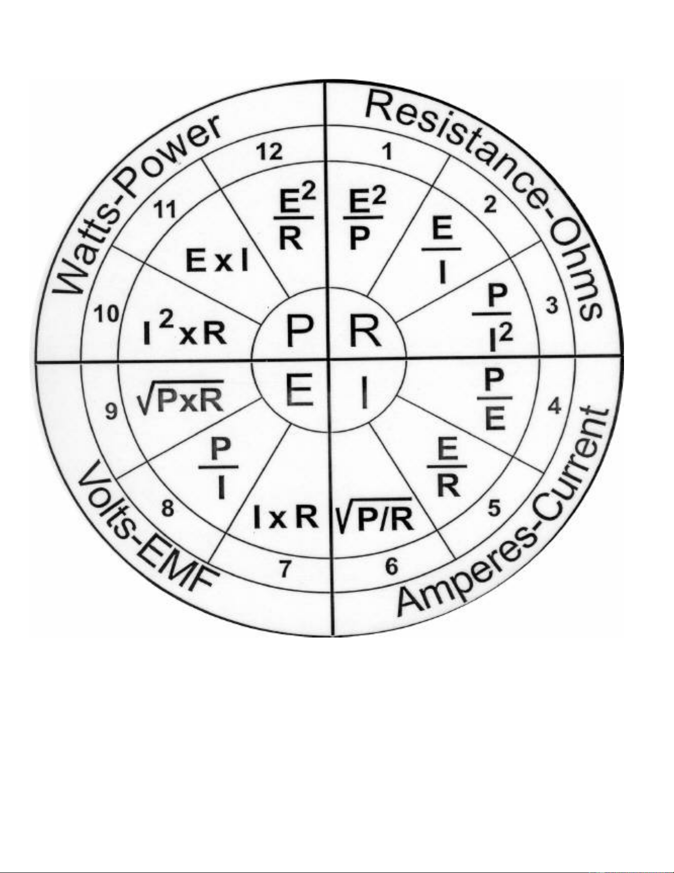
Pressure-Temperature Chart
Temperature °F Temperature °F Temperature °F
PSIG R134a R404
A
PSIG R134a R404
A
PSIG R134a R404
A
5* -30 -65 30 32 -6 105 89 49
4* -29 -63 31 33 -5 110 92 52
3* -27 -62 32 34 -4 115 94 54
2* -25 -60 33 35 -2 120 97 56
1* -24 -59 34 36 -1 125 99 58
0 -22 -57 35 37 0 130 102 61
1 -19 -54 36 38 1 135 104 63
2 -16 -52 37 40 2 140 106 65
3 -13 -49 38 41 3 145 108 67
4 -11 -47 39 42 4 150 111 69
5 -9 -44 40 43 5 155 113 71
6 -6
-42 42 45 6 160 115 73
7 -4 -40 44 46 8 165 117 75
8 -2 -38 46 48 10 170 119 77
9 0 -36 48 50 12 175 121 79
10 2 -34 50 52 14 180 122 81
11 4 -32 52 54 15 185 124 83
12 6 -31 54 55 17 190 126 84
13 8 -29 56 57 18 195 128 86
14 9 -27 58 59 20 200 130 88
15 11 -26 60 60 21 205 131 89
16 13 -24 62 62 23 210 133 91
17 14 -23 64
63 24 220 136 94
18 16 -21 66 65 26 230 140 97
19 17 -20 68 66 27 240 143 100
20 19 -18 70 68 29 250 146 103
21 20 -17 72 69 30 260 149 106
22 22 -16 74 70 31 275 153 110
23 23 -14 76 72 33 290 157 114
24 24 -13 78 73 34 305 161 118
25 26 -12 80 74 35 320 164 121
26 27 -10 85 78 38 335 168 125
27 28 -9 90 81 41 350 172 128
28 29 -8 95 83 44
365 175 132
29 31 -7 100 86 47
* Inches mercury below one atmosphere