Questions, problems, missing parts? Before returning to your retailer, call our
customer service department at (877) 888-8225, 8 a.m. - 8 p.m., EST, Monday - Sunday.
You could also contact us at [email protected].
Serial Number Purchase Date
SM21136
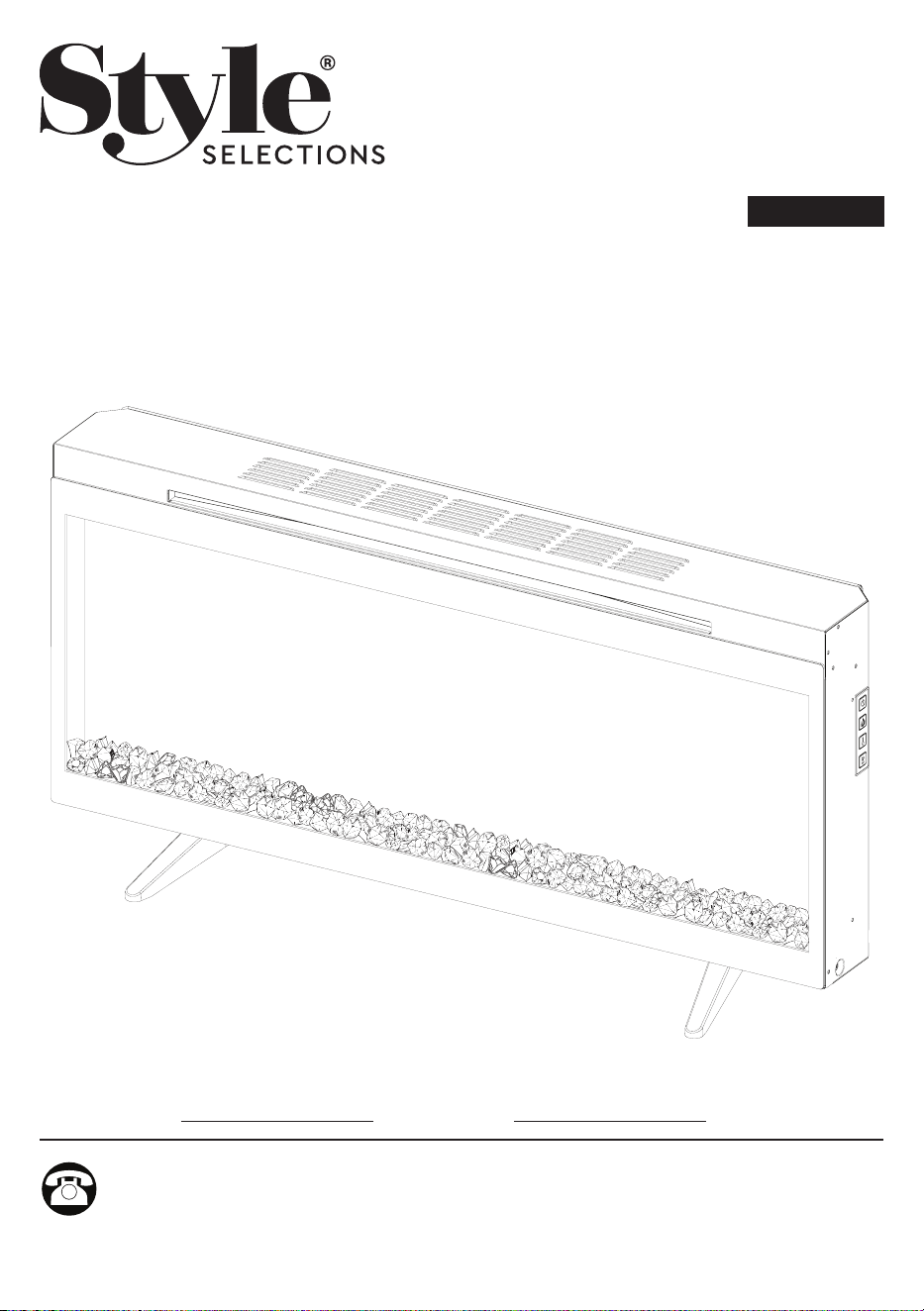
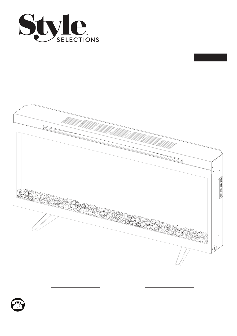
MODEL # 42HF295FGT
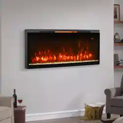
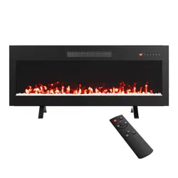
42 IN WALL MOUNT
ELECTRIC FIREPLACE
Spanish p.22
STYLE SELECTIONS and logo design are
trademarks or registered trademarks of LF, LLC. All
rights reserved.
ATTACH YOUR RECEIPT HERE
ITEM #3730319
2A2512
TABLE OF CONTENTS
PRODUCT SPECIFICATIONS
VOLTAGE 120VAC, 60 Hz
AMPS 12.5 Amps
WATTS 1500 Watts
Product Specications ............................................................................................................2
Safety Information......................................................................................................................3
Package Contents......................................................................................................................5
Hardware Contents....................................................................................................................6
Assembly Instructions................................................................................................................7
Installation - Wall Mounting........................................................................................................8
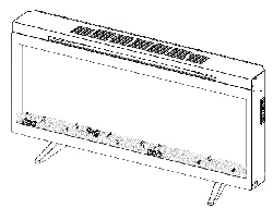
Installation - Pedestal base........................................................................................................12
Operating Instructions..............................................................................................................14
Troubleshooting......................................................................................................................16
FCC/IC Information..................................................................................................................18
Care and Maintenance..............................................................................................................18
Warranty..................................................................................................................................19
Battery Replacment .................................................................................................................20
Replacement Parts List.............................................................................................................21
3A2512
SAFETY INFORMATION
When using electrical appliances, basic precautions including the following should
always be followed to reduce the risk of re, electrical shock, and injury to persons:
1. Read all instructions before using this appliance.
2. WARNING: High temperatures may be generated under certain abnormal
conditions. Do not partially or fully cover or obstruct the front of this heater. In
order to avoid overheating, do not cover the heater.
3. CAUTION: Never leave the heater operating unattended. Extreme caution is
necessary if unsupervised children or people of reduced physical or mental
capabilities are nearby.
4. The appliance is not to be used by children or persons with reduced physical,
sensory or mental capabilities, or lack of experience and knowledge, unless they
have been given supervision or instruction.
5. Always unplug this appliance when not in use.
6. Do not operate any heater with a damaged cord or plug or after the appliance
malfunctions, or if it has been dropped or damaged in any manner.
7. If the supply cord is damaged, it must be replaced by the manufacturer, its service
agent or similarly qualied persons in order to avoid a hazard.
8. Do not use outdoors.
9. This heater is not intended for use in bathrooms, laundry areas and similar indoor
locations. Never locate this appliance where it may fall into a bathtub or other
water container.
10. Do not run cord under carpeting. Do not cover cord with throw rugs, runners or the
like. Arrange cord away from trac areas and where it will not be tripped over.
11. To disconnect this appliance, turn controls to the o position, then remove plug
from outlet.
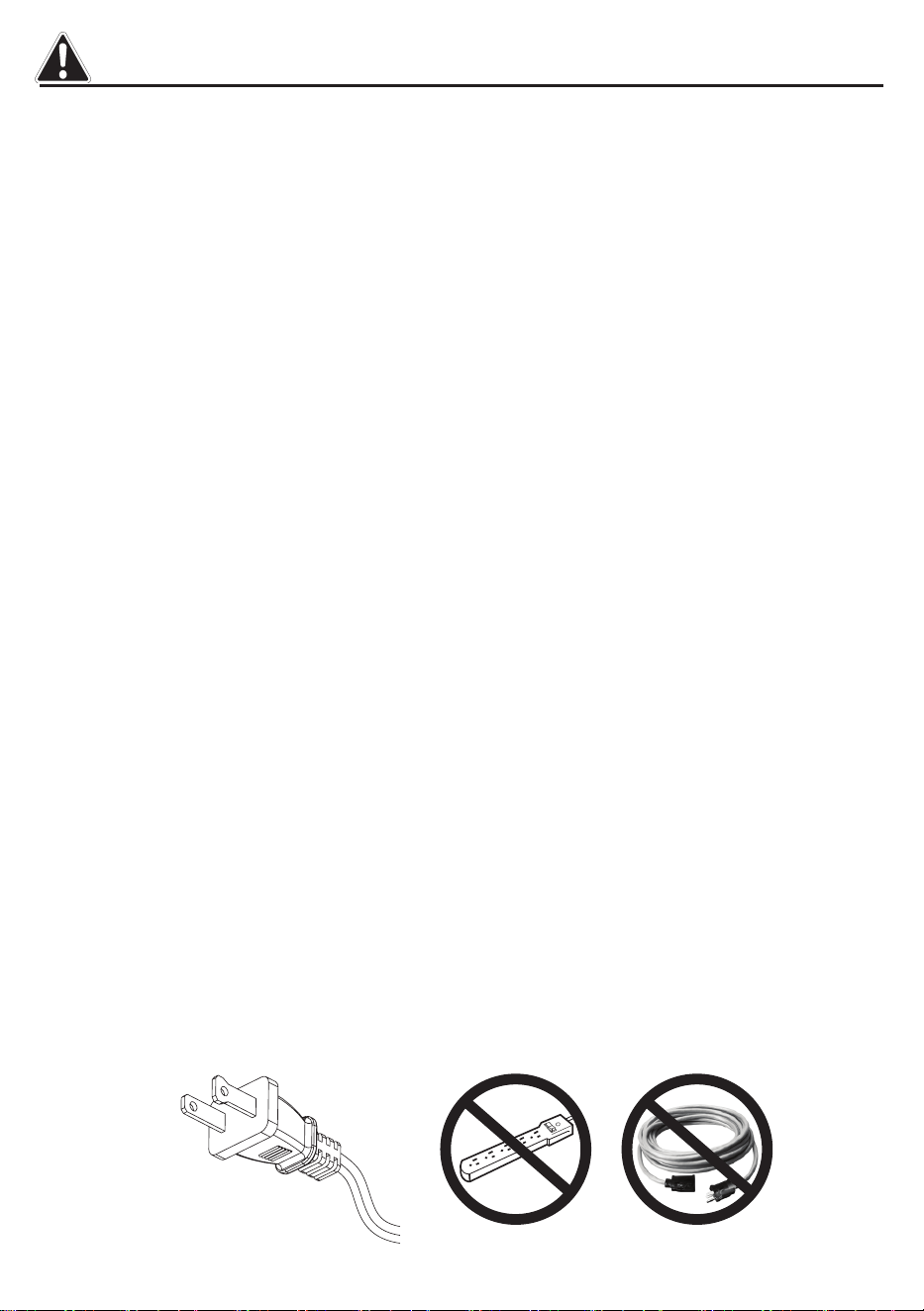
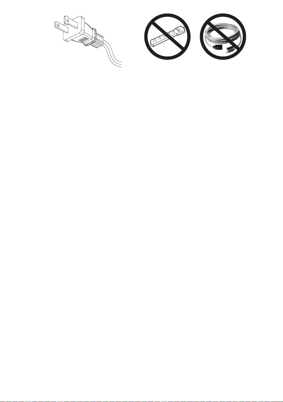
12. This product is equipped with a polarized plug (one blade is wider than the other
blade). To reduce the risk of electrical shock, this plug will t into a polarized outlet
only one way. This is a safety feature. If you are unable to insert the plug into
the electrical outlet, try reversing the plug. If the plug still does not t, contact a
qualied electrician.Do not insert or allow foreign objects to enter any ventilation
or exhaust opening as this may cause an electric shock or re, or damage the
appliance.

4
A2512
SAVE THESE INSTRUCTIONS
13. When installed, this appliance must be in accordance with local codes or, in the
absence of local codes, with the current CSA C22.1 Canadian Electrical Code or for
U.S.A. installations, follow local codes and the National Electrical Code, ANSI/NFPA
NO.70.
14. When installed, this appliance must be in accordance with local codes or, in the
absence of local codes, with the current CSA C22.1 Canadian Electrical Code or
for U.S.A. installations, follow local codes and the National Electrical Code, ANSI/
NFPA NO.70.
15. To prevent a possible re, do not block air intakes or exhaust in any manner. Do
not use on soft surfaces, like a bed, where opening may become blocked.
16. This appliance has hot and arcing or sparking parts inside. Do not use it in
areas where gasoline, paint or ammable liquids are used or stored. This
replace should not be used as a drying rack for clothing. Christmas stockings or
decorations should not be hung in the area of it.
17. Use this appliance only as described in the manual. Any other use not
recommended by the manufacturer may cause re, electric shock or injury to
persons.
18. This heater may include a visual alarm to warn that parts of the heater are
getting excessively hot. If the alarm illuminates, immediately turn the heater o
and inspect for any objects on or adjacent to the heater that may have blocked
the airow or otherwise caused high temperatures to have occurred. DO NOT
OPERATE THE HEATER WITH THE ALARM ILLUMINATING.
A
C
I
E
D
H
F
G
B
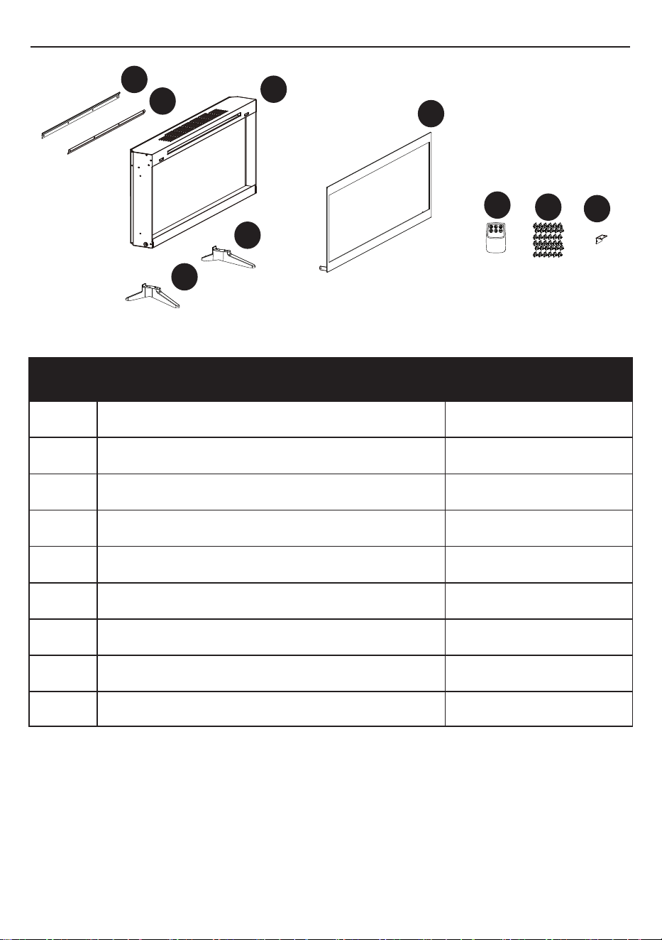
PACKAGE CONTENTS
B
D
E
H
I
F
A
C
G
PART DESCRIPTION QUANTITY
A Mounting Bracket A 1
B Mounting Bracket B 1
C Fireplace 1
D Glass Panel 1
E Left foot 1
F Right foot 1
G Remote Control 1
H Plastic Crystals Varies
I Mounting Bracket I 1
5A2512
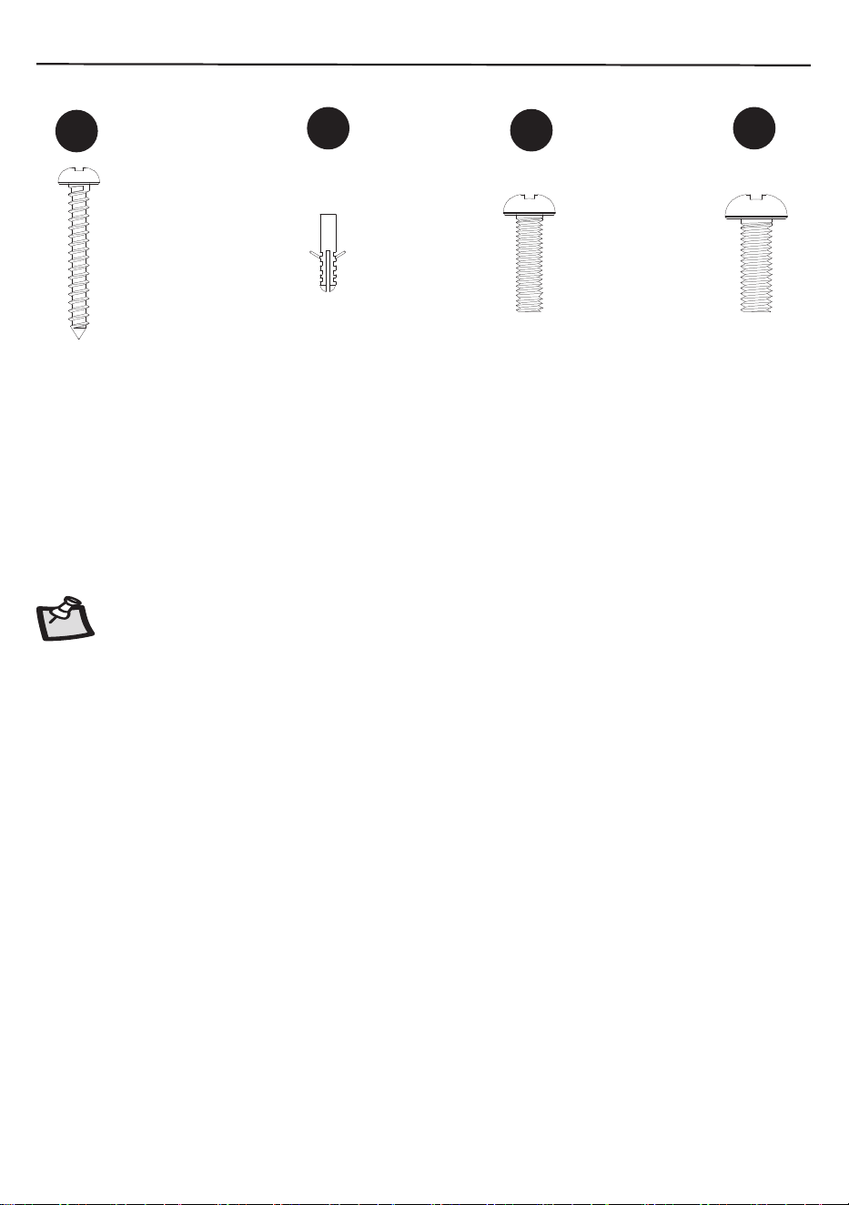
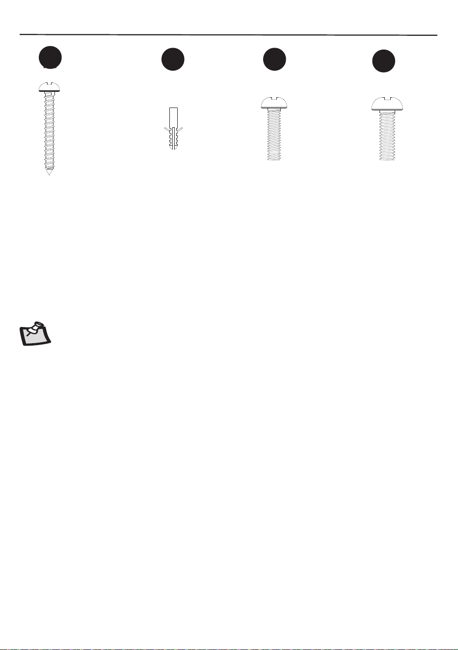
HARDWARE CONTENTS
Qty: 6
Qty:6
Qty: 8
Pre-atadched 2pcs
Qty: 4
AA
BB
CC
DD
Screw
Wall Anchors
Screw
Screw
M4x12mm
M6x12mm
NOTE:Hardware not shown to actual size.
6A2512
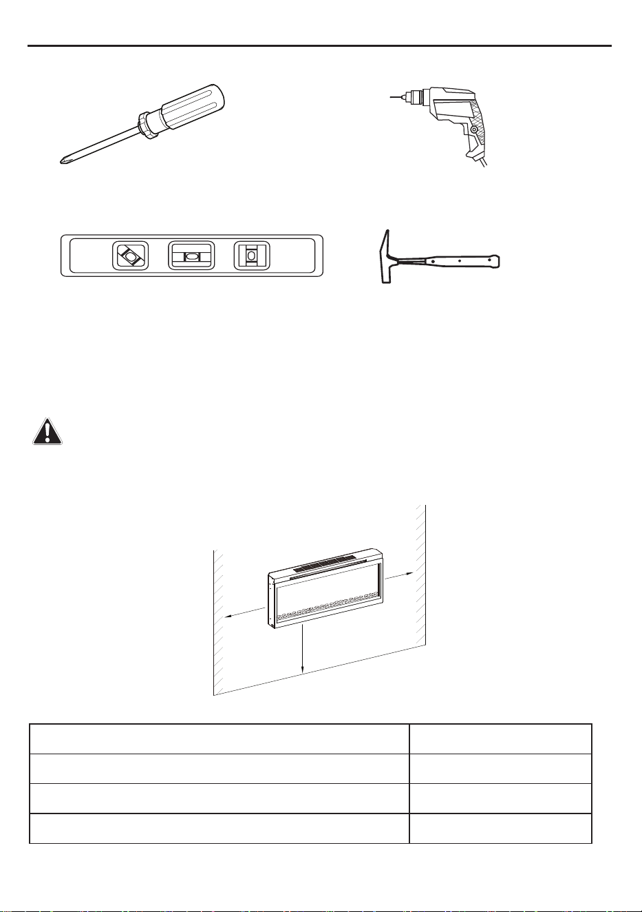
Phillips screwdriver
Tools Required for Assembly (not included): Phillips screwdriver, Drill, Hammer, Level
Drill
Level
Hammer
INSTALLING THE ELECTRIC FIREPLACE
The electric replace may be installed in many locations in a home. When choosing a location be
sure to follow the general instructions included. For best results install out of direct sunlight.
The product cannot be operated without all the parts installed.
WARNING: Keep drapery and other furnishings at least 3 ft / 91.4 cm from the front and sides of the
electric replace.
Sides 5 cm
Floor 75 cm
Top 5 cm
Back 0 cm
Clearance to combustible liquids
Min 75cm
29.5 in
Min 5cm
2 in
Min 5cm
2 in
ASSEMBLY INSTRUCTIONS
7
A2512
1
2
3
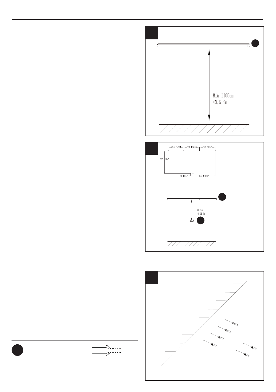
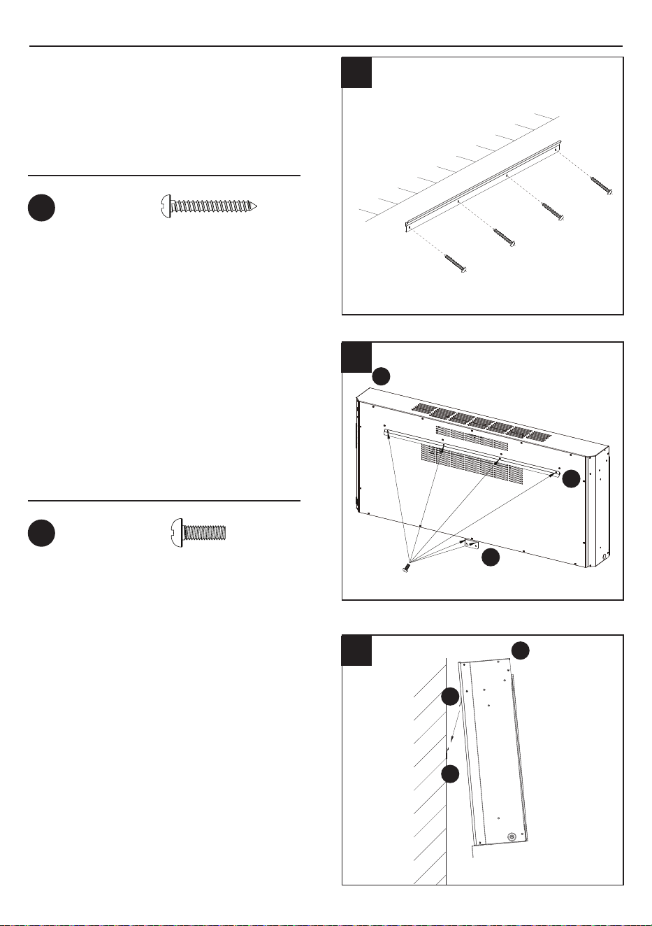
INSTALLATION - WALL HANGING
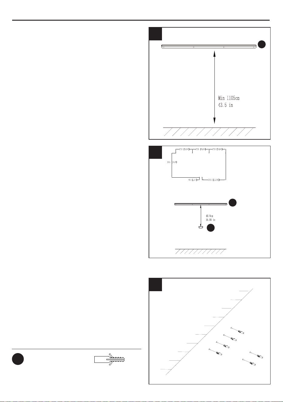
2. Use a level to align the bracket and mark
the six holes with a pencil.
1. Choose a wall location to attach the
Mounting Bracket (A). Position the Mounting
Bracket (A) in the desired location.
Min 1105cm
43.5 in
A
A
I
3. Drill 6 holes 0.25 in / 7mm in the wall. Insert
the wall anchors (BB) into the holes using a
hammer (Fig. 3).
Wall Anchor
x 6
Hardware Used
BB
8A2512
Hardware Used
Hardware Used
x 4
x 6
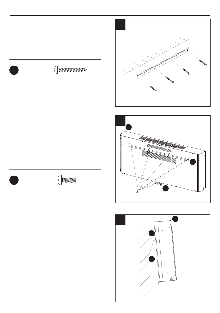
INSTALLATION - WALL HANGING
4. Attach the mounting bracket (A) to the
wall, fastening the 4 screws (AA) into the
wall anchors.
Screw
Screw
AA
CC
5. Hang the replace (C) on the hooks
at bottom of mounting bracket (B) and
push the Fireplace (C) into the Mounting
Bracket (I).
6. Hang the replace (C) on the hooks
at bottom of mounting bracket (A) and
push the Fireplace (C) into the Mounting
Bracket (A).
4
5
6
C
B
B
C
A
I
9A2512

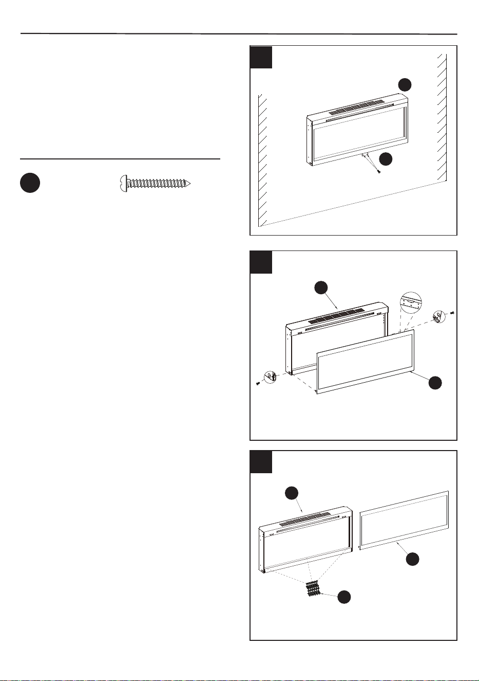
INSTALLATION - WALL HANGING
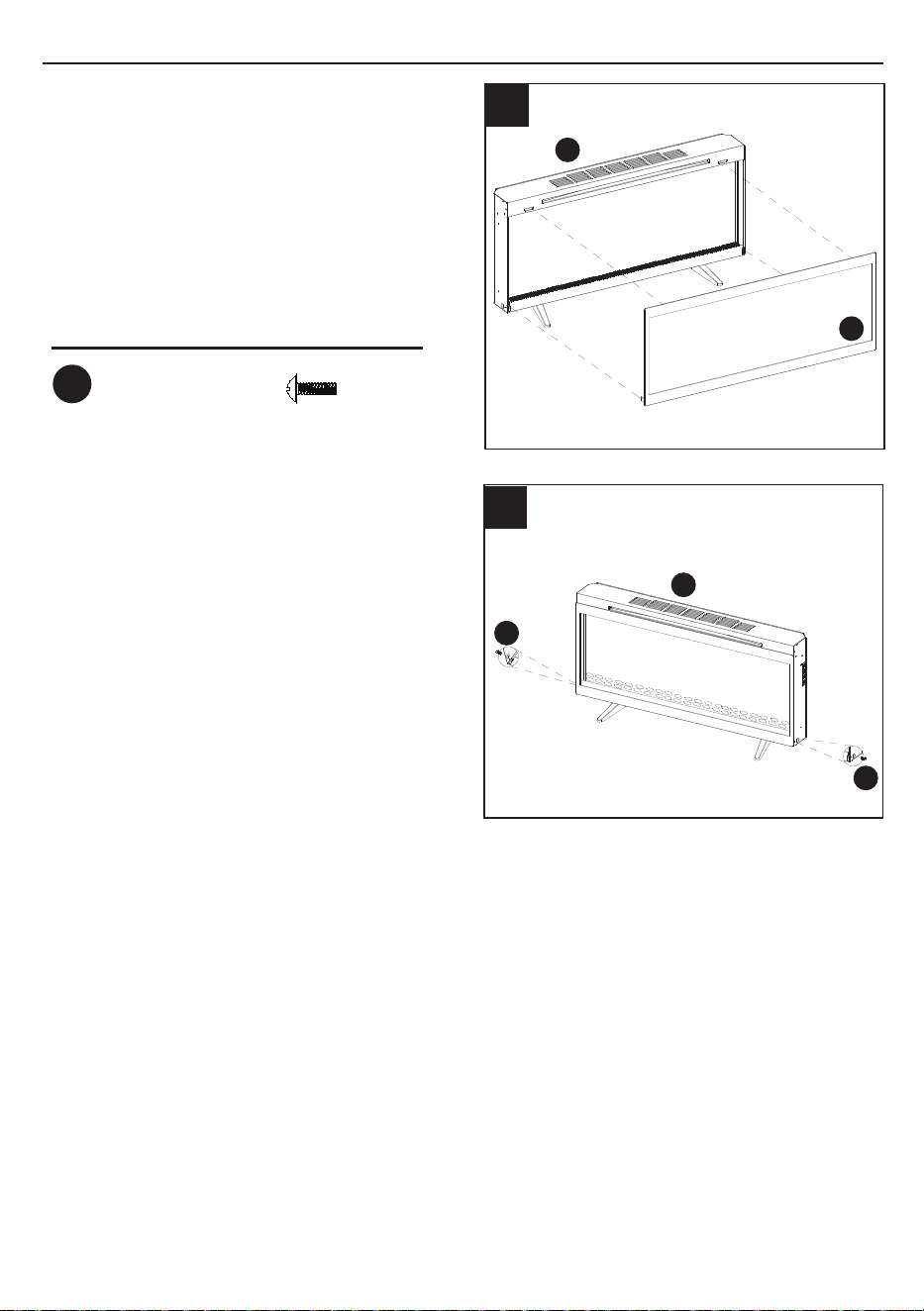
7. Using the two screws (AA) to secure the
replace to the mounting bracket.
8. Unscrew the 2 Pre-atached screws (CC) on
both sides of Glass panel(D). Remove the
Glass panel (D).
9. Place the plastic Crystals(H) into the replace.
7
8
9
D
C
H
D
C
I
C
C
C
D
D
H
C
Hardware Used
x 2
Screw
AA
10A2512
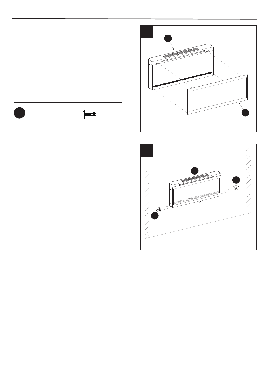
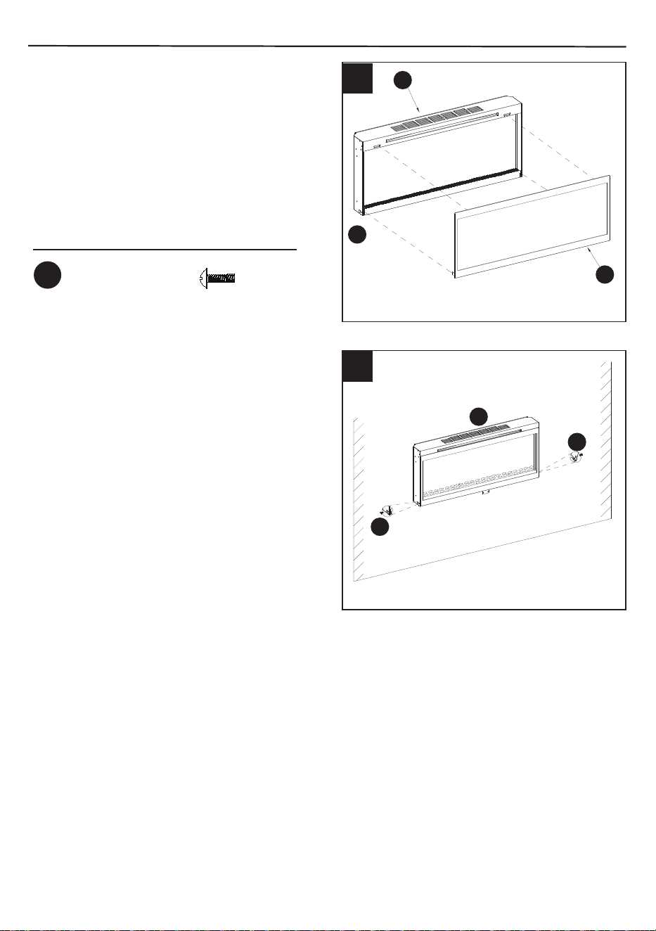
INSTALLATION - WALL HANGING
11.Re-fasten the two screws (CC) removed in
Step 8 to secure the glass panel replace to
the replace.
10. Hang the glass panel (D) on the replace
and gently push on the lower part of the
frame until it snaps into place.
10
11
C
C
CC
CC
D
Hardware Used
Screw
x 2
CC
11
A2512
D
C
CC
I
D
C
C
D
Hardware Used
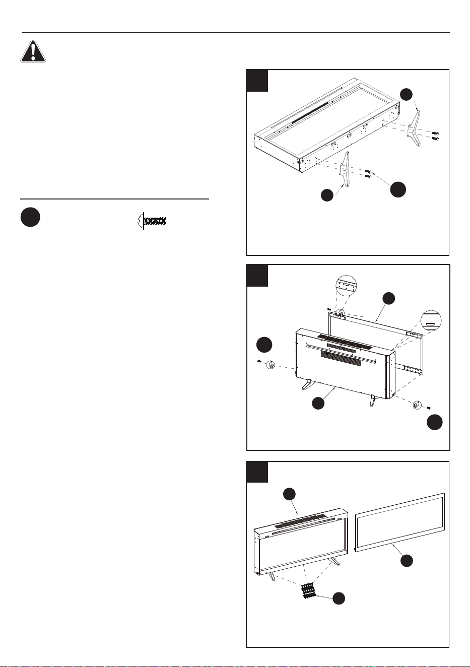
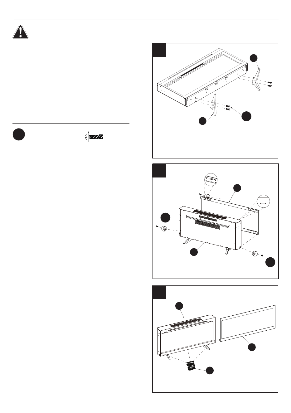
INSTALLATION - PEDESTAL BASE
F
D
DD
CC
CC
E
C
C
D
H
Screw
x 4
DD
1. Fasten Left Support foot (E) and Right
Support foot (F) to the replace with the
provided screw (DD) (Fig 1).
The product cannot be operated without all the parts installed.
2. Unscrew the 2 pre-atached screws (CC) on
both sides of Glass panel(D). Remove the
Glass panel (D).
3. Place the plastic Crystals(H) into the
replace.
1
2
3
12A2512
CC
CC
D
C
C
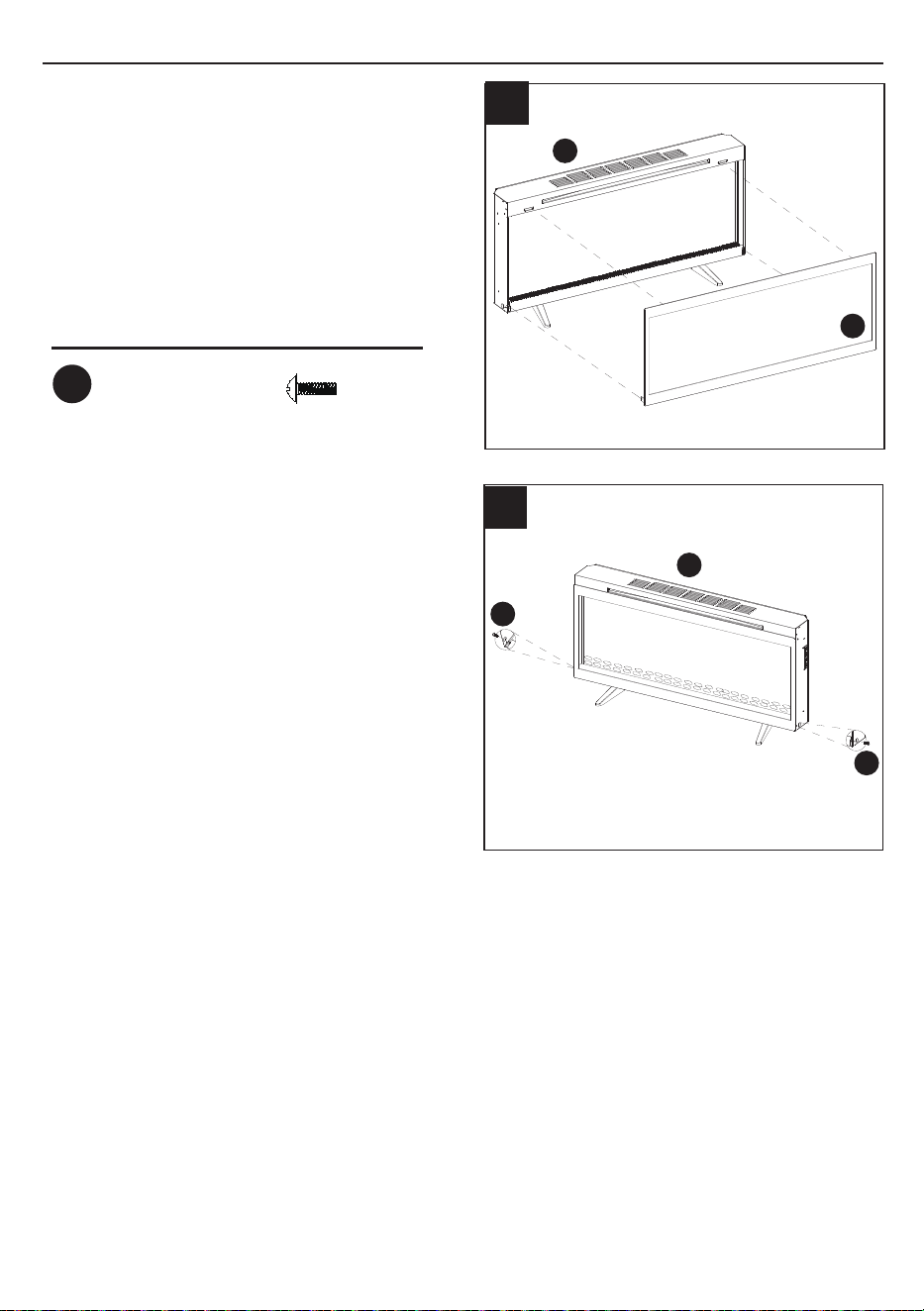
5. Re-fasten the two screws (CC) removed in
Step 2 to secure the glass panel replace
to the replace.
4.Hang the glass panel (D) on the replace
and gently push on the lower part of the
frame until it snaps into place.
Hardware Used
Screw
x 2
CC
4
5
INSTALLATION - PEDESTAL BASE
13
A2512
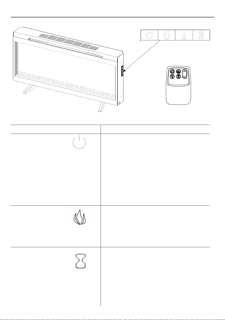
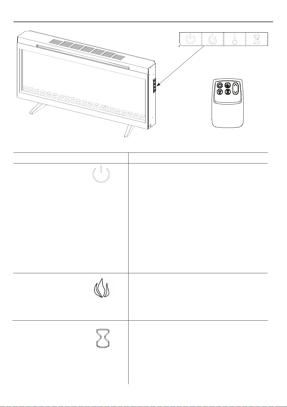
OPERATING INSTRUCTIONS
FUNCTION
FOWER
The POWER button supplies power to all the
functions of the replace. Pressing the POWER
button again will put the replace in standby mode.
This will turn o all functions at once but will hold
the settings in the memory. By pressing the Power
button again the unit will turn on at the same
settings.
With the power on press and hold the Power button
on the control panel for 10 seconds to disable or
re-enable the heater function. Once disabled or re-
enabled the emberbed lights will ash multiple times.
ICON
DESCRIPTION
CONTROL PANEL LOCATION
Remote Control
FLAME
There are 5 brightness levels that can be selected
and OFF (00) setting.
Settings F5 - F1 decrease in brightness.
TIMER
Pressing the timer button will cycle through the timer
settings; 30 minutes, 1 Hour, 2H, 3H, 4H, 5H, 6H,
7H, 8H, 9H and 00 (OFF).
To cancel the timer once it has been set, press the
TIMER button twice and the display will ash 00 to
show the timer has been canceled.
14A2512
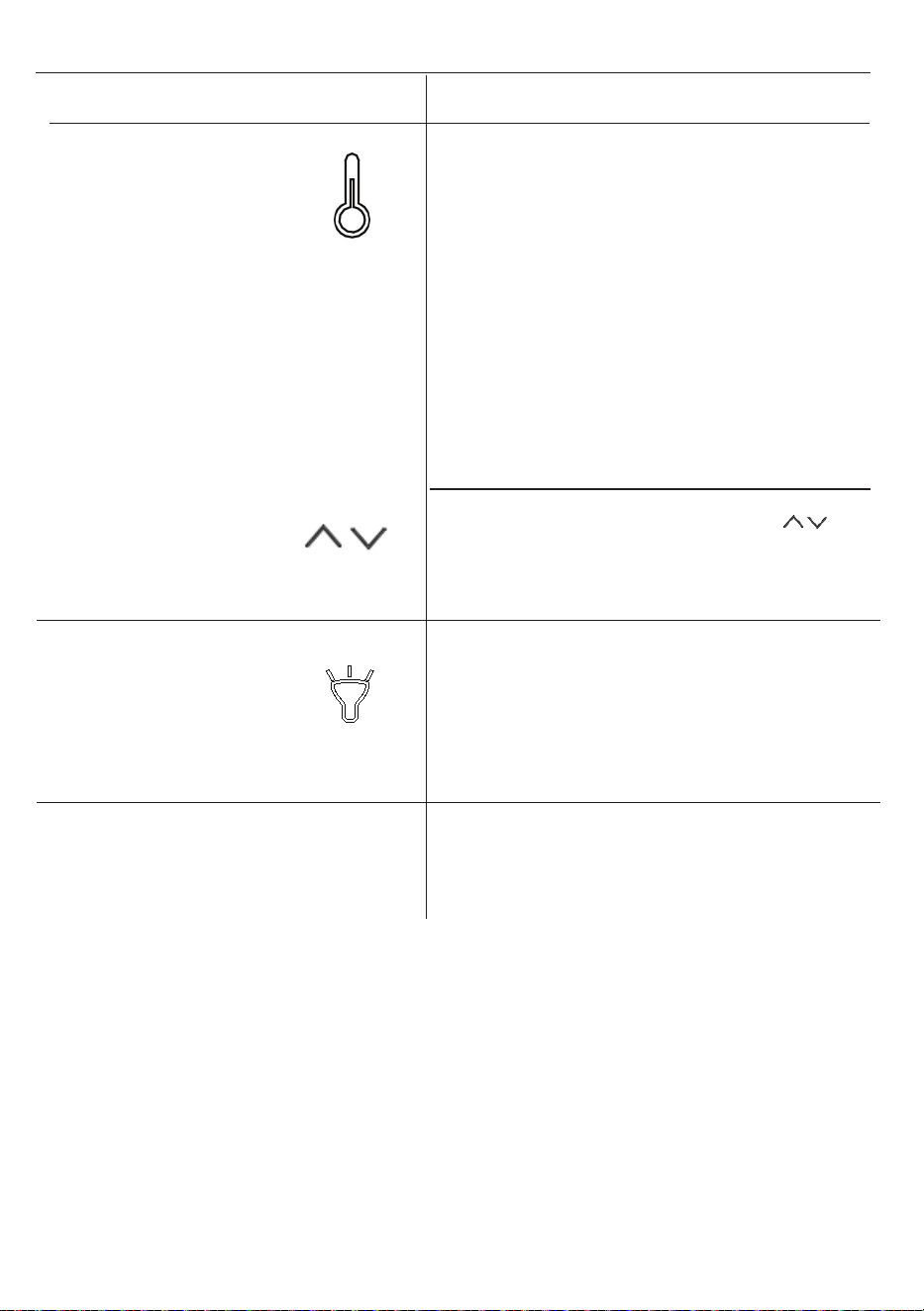
OPERATING INSTRUCTIONS
FUNCTION
ICON
DESCRIPTION
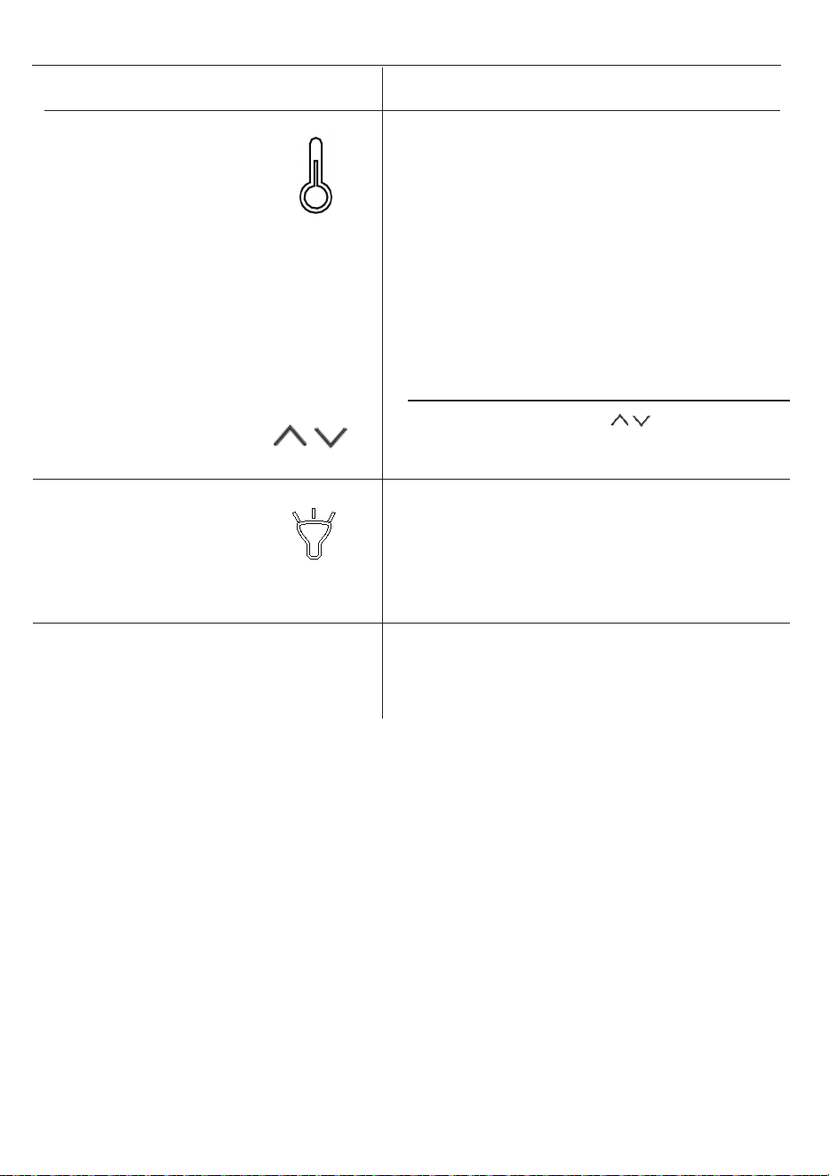
HEATER
The replace contains two infrared quartz heating
elements.
The default temperature is 72 °F (22 °C).
The thermostat setting range is 62 °F - 82 °F or 17
°C - 27 °C or continuously ON or 00 (OFF). To set
ame eect so that it works without heat, press the
heater button until the display shows “00”.
The thermostat is adjustable by 2 °F or 1 °C
increments.
To change between °F and °C press and hold the
HEATER button on the control panel for 3 seconds.
The up and down buttons “ ” on the remote will
increase / decrease temperature setting.
UPLIGHTS
Pressing the UPLIGHT button on the remote
will change the uplight between the 5 settings:
1(amber), 2(blue), 3(amber/ blue), AU(auto-cycling)
and 00 (OFF) .
COOL DOWN CYCLE
Before the replace powers o, the fan will continue
to run for a period of time to cool down the internal
parts.
15A2512
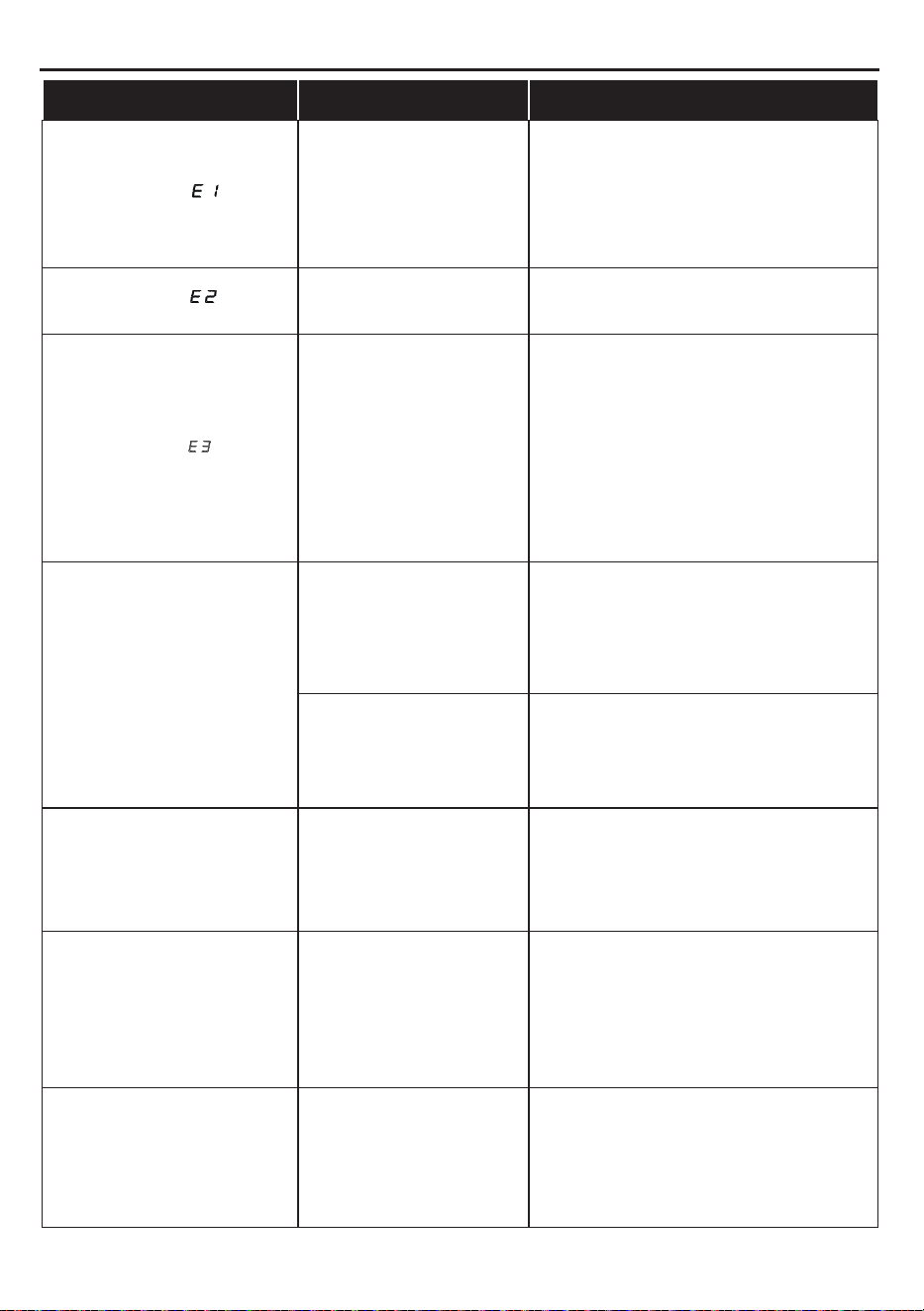
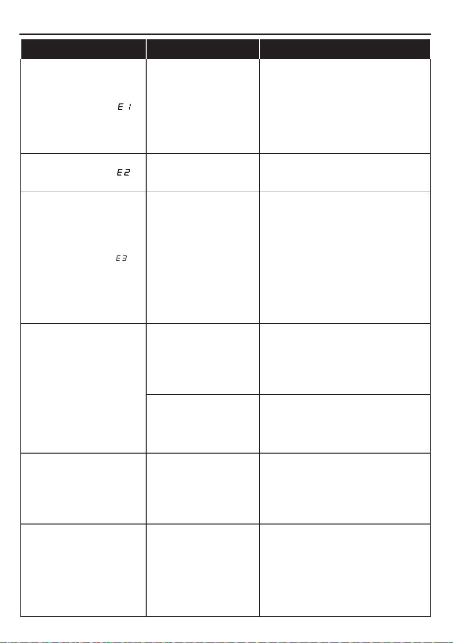
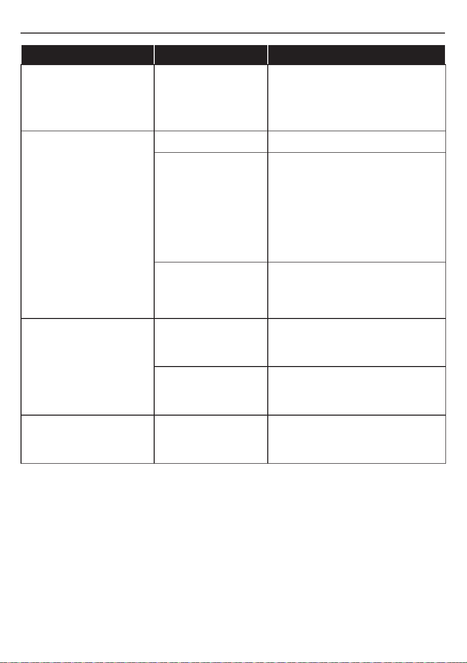
TROUBLESHOOTING
PROBLEM POSSIBLE CAUSE CORRECTIVE ACTION
Display shows “ ”
The thermostat sensor is
broken or disconnected.
Unplug the replace, remove the back
panel of the replace and check that
the thermostat is plugged into the main
circuit board. If this does not solve the
problem contact customer service for a
replacement thermostat sensor.
Display shows “ ”
The thermostat sensor
short circuited.
Contact customer service for a
replacement thermostat sensor.
Display shows “ ”
Manual Reset overheat
protection has triggered.
Inspect the heater and check that the
air inlets and outlets are not blocked
as this may cause overheating. Unplug
the heater for 30 minutes and allow
it to cool down. Replug and operate,
monitor the heater for signs of
overheating, if the problem persists
discontinue use of the heater and
contact customer service.
Heater does not blow warm
air.
Cool down cycle.
Normal operation, will continue to
run
for less than one minute
before
shutting down.Times will vary based
on temperatures. During this time cool
air will blow.
Thermostat setting is
preventing heater from
turning on.
Adjust the temperature settings to ensure
that the thermostat is set higher than the
current room temperature.
There is no power.
There is no power to the
unit.
Check that unit is plugged into a standard
120V outlet. Press the power button
several times and make sure the power
is set to the “ON” position.
The heater does not work,
but Power and Heater
settings are “ON” and
thermostat is set.
Manual reset overheat
protection
triggered.
Turn the POWER to “OFF” and unplug
the unit from the wall outlet for 5
minutes. After 5 minutes plug the unit
back into wall outlet, and operate
as normal. If the problem persists
contact customer service.
Flame eect works but
heaterfunction does not,
and the ame eect ashes
when the heater button is
pressed.
The heater is disabled.
With the power on press and hold the
POWER button on the control panel
for 10 seconds. Once re-enabled the
unit.
16A2512
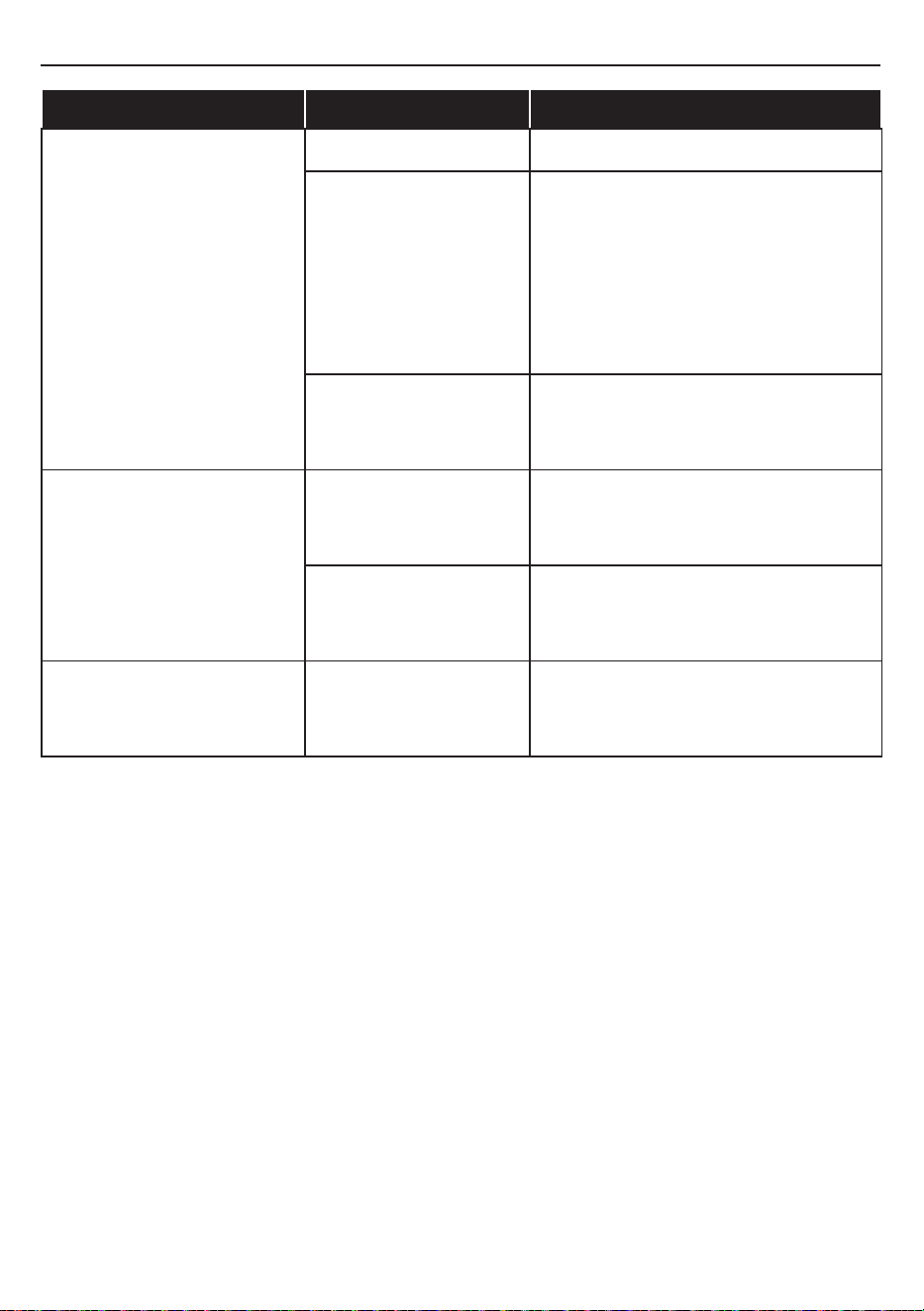
PROBLEM POSSIBLE CAUSE CORRECTIVE ACTION
Remote Control is not
working.
No batteries Change the remote batteries.
Poor Signal
Operate remote transmitter at a slow
measured pace.
Press the remote control buttons with
an even motion and gentle pressure.
Repeatedly pressing buttons in rapid
succession may cause the transmitter
to malfunction.
Distance
Operate the remote at a distance less
than 20 feet from the front of the
appliance; point the remote at the
control panel.
The noise when the heater is
on is louder than normal.
Dirty or obstructed air
intakes.
Check the air intakes for obstructions
or high dust build up.
Defective Blower/Heater
Assembly
Contact Customer Service for a new
Heater/Blower Assembly.
Abnormal noise when the
heater is not on and the
ame eect is on.
The spinner motor is
defective.
Contact Customer Service for a new
Spinner Motor.
TROUBLESHOOTING
17A2512

Warning: Changes or modications to this unit not expressly approved by the party responsible for
compliance could void user’s authority to operate the equipment.
NOTE: This equipment has been tested and found to comply with the limits for Class B digital
device, pursuant to part 15 of the FCC Rules. These limits are designed to provide reasonable
protection against harmful interference in a residential installation. This equipment generates,
uses, and can radiate radio frequency energy and, if not installed and used in accordance with the
instructions, may cause harmful interference to radio communications.
However, there is no guarantee that interference will not occur in a particular installation. If
this equipment does cause harmful interference to radio or television reception, which can be
determined by turning the equipment o and on, the user is encouraged to try to correct the
interference by one or more of the following measures:
• Reorient or relocate the receiving antenna.
• Increase the separation between the equipment and the receiver.
• Connect the equipment into an outlet on a circuit dierent from that to which the receiver is
connected.
• Consult the dealer or an experienced radio/TV technician for help.
This device complies with Part 15 of the FCC Rules. Operation is subject
to the following two conditions:
(1) This device may not cause harmful interference, and
(2) This device must accept any interference received, including interference that may cause
undesired operation.
Twin-Star International Inc.
1690 S. Congress Ave., Suite 210, Delray Beach, FL 33445
1-866-661-1218
This Class B digital apparatus complies with Canadian ICES-003.
• Clean the trim using a soft cloth, slightly dampened with citrus oil based product and bu
with a clean soft cloth.
• Citrus oil based products are recommended for cleaning and can be found at
supermarkets or hardware stores.
• WARNING: Electrical outlet wiring must comply with local building codes and other
applicable regulations to reduce the risk of re, electrical shock and injury to persons.
• Warning: Disconnect power before attempting any maintenance or cleaning to reduce the
risk of re, electrical shock or personal injury.
FCC/IC INFORMATION
CARE AND MAINTENANCE
18A2512

The manufacturer warrants that your new Electric Fireplace is free from manufacturing and
material defects for a period of one year from date of purchase, subject to the following
conditions and limitations.
1. Install and operate this appliance in accordance with the installation and operating
instructions furnished with the product at all times. Any unauthorized repair, alteration,
willful abuse, accident, or misuse of the product shall nullify this warranty.
2. This warranty is non-transferable, and is made to the original owner, provided that the
purchase was made through an authorized supplier of the product.
3. The warranty is limited to the repair or replacement of part(s) found to be defective in
material or workmanship, provided that such part(s) have been subjected to normal
conditions of use and service, after said defect is conrmed by the manufacturer’s
inspection.
4. The manufacturer may, at its discretion, fully discharge all obligations with respect to this
warranty by refunding the wholesale price of the defective part(s).
5. Any installation, labor, construction, transportation, or other related costs/expenses
arising from defective part(s), repair, replacement, or otherwise of same, will not be
covered by this warranty, nor shall the manufacturer assume responsibility for same.
6. The owner/user assumes all other risks, if any, including the risk of any direct, indirect or
consequential loss or damage arising out of the use, or inability to use the product, except
as provided by law.
7. All other warranties – expressed or implied –with respect to the product, its components
and accessories, or any obligations/liabilities on the part of the manufacturer are hereby
expressly excluded.
8. The manufacturer neither assumes, nor authorizes any third party to assume on its
behalf, any other liabilities with respect to the sale of the product.
9. The warranties as outlined within this document do not apply to non accessories used in
conjunction with the installation of this product.
10. This warranty gives you specic legal rights, and you may also have other rights which
vary from state to state.
This warranty is void if:
a. The replace is subjected to prolonged periods of dampness or condensation.
b. Any unauthorized alteration, willful abuse, accident, or
misuse of the product.
c. You do not have the original receipt of purchase.
1-YEAR LIMITED WARRAARITY
19
A2512
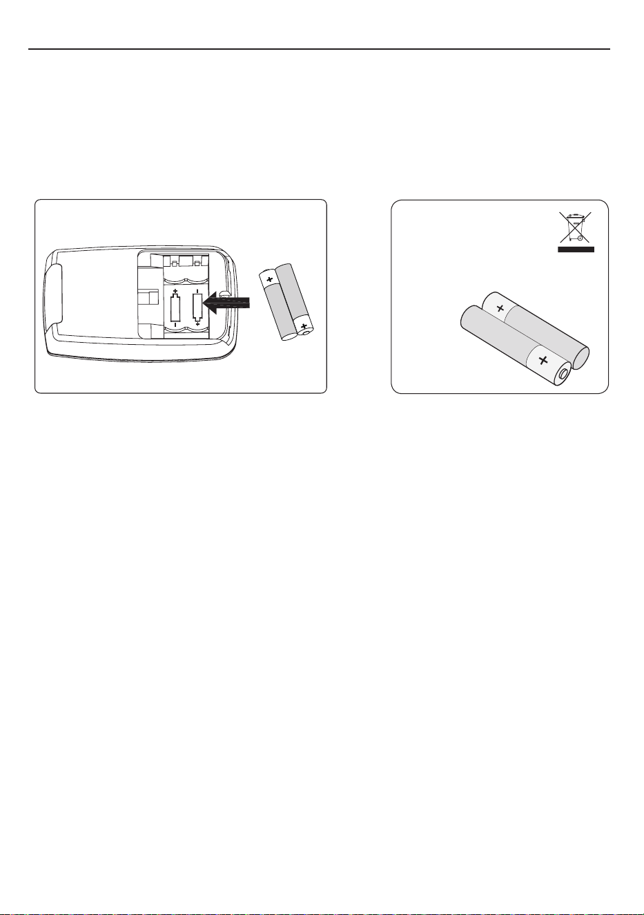
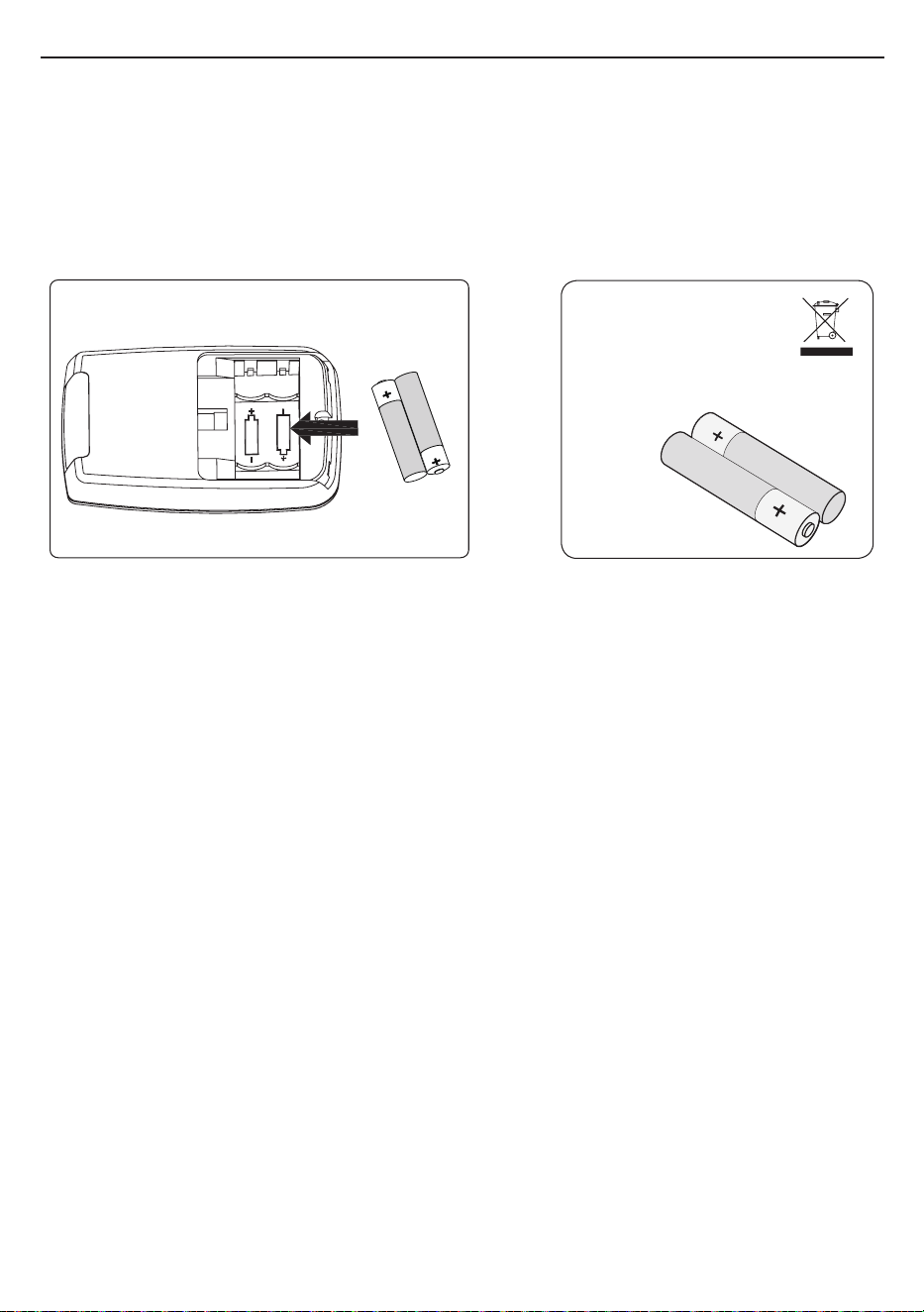
BATTERY REPLACEMENT
AAA 1.5V
AAA 1.5V
NOTE: Battery disposal
Please always dispose
of batteries at a suitable
recycling point.
CAUTION:
• Always purchase the correct size (AAA) and grade of battery most suitable for the intended use.
• Replace all batteries of a set at the same time.
• Clean the battery contacts and also those of the device prior to battery installation.
• Ensure the batteries are installed correctly with regard to polarity (+ and -).
• Remove batteries from equipment which is not to be used for an extended period of time.
• Remove used batteries promptly.
For recycling and disposal of batteries to protect the environment, please check the internet or your
local phone directory for local recycling centers and / or follow local government regulations.
NOTE: Do not mix old and new batteries.
Do not mix alkaline, standard (carbon zinc), or rechargeable (nicad, ni-mh, etc.) batteries.
Non-rechargeable batteries are not to be recharged.
Exhausted batteries are to be removed from the product.
20
A2512
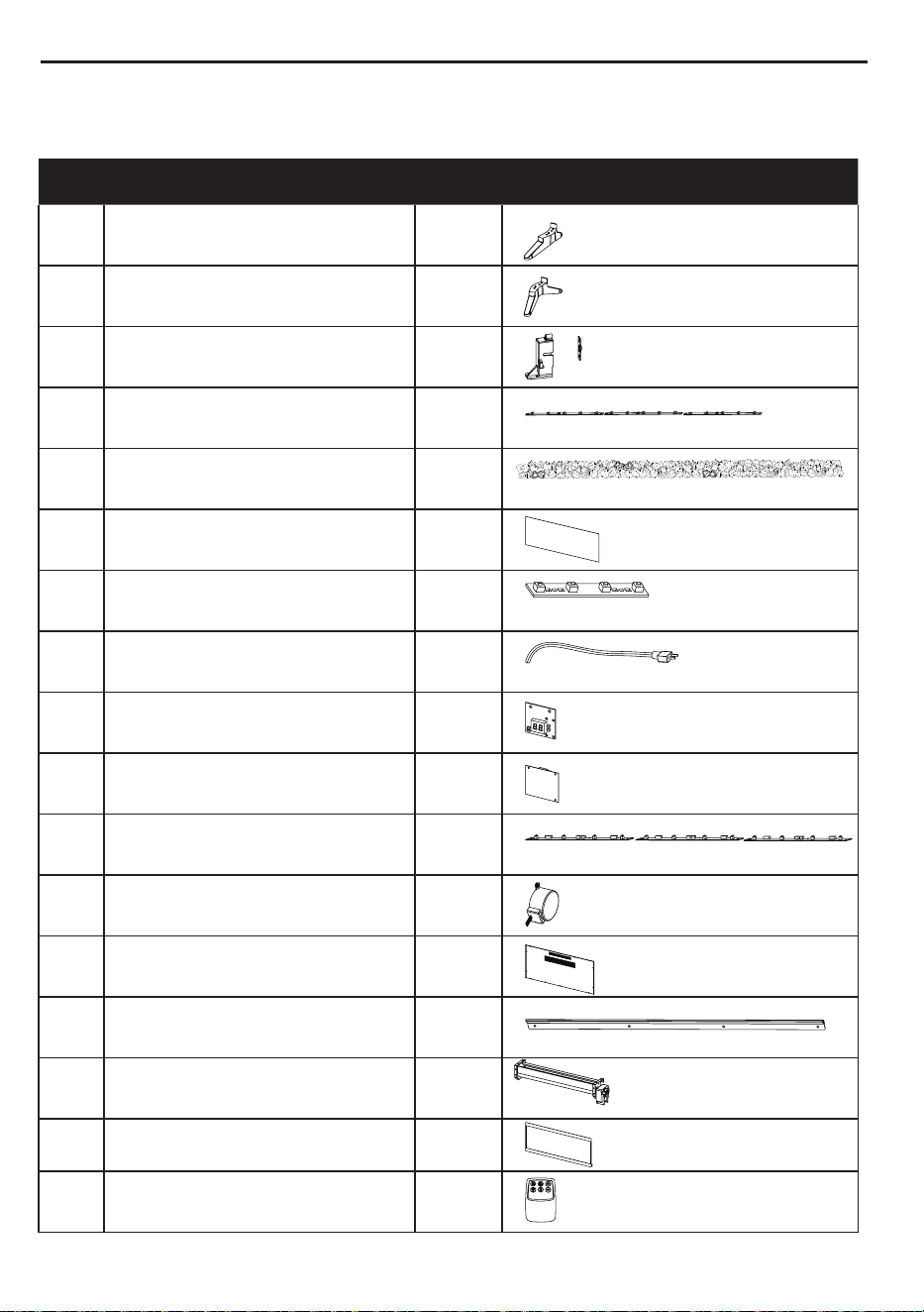
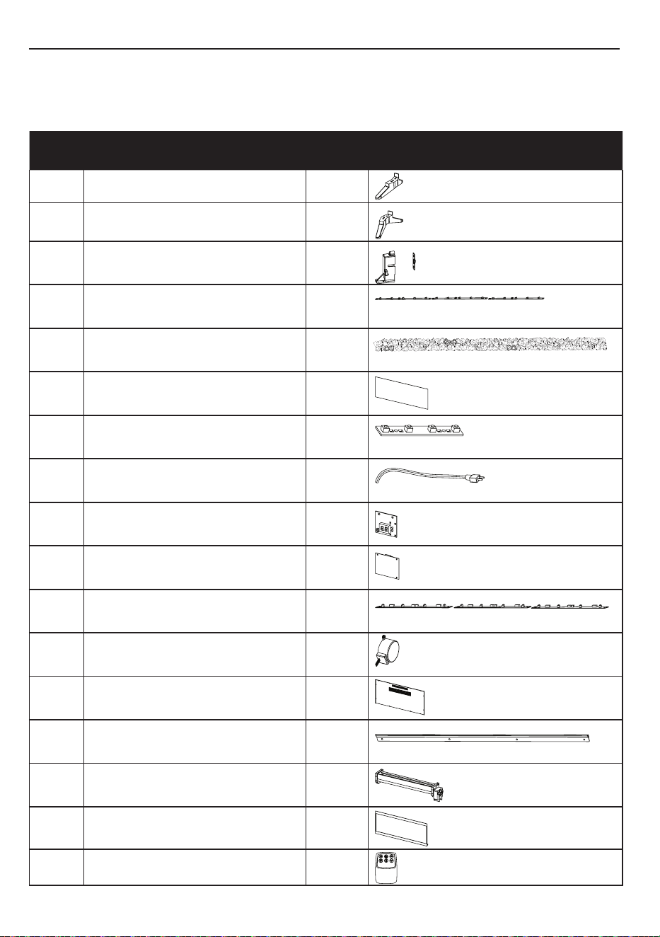
REPLACEMENT PARTS LIST
For replacement parts, call our customer service department at (877) 888-8225, 8 a.m. - 8
p.m., EST, Monday - Sunday. You could also contact us at [email protected].
PART PART NAME QTY PART NUMBER
1 Left Foot 1
Y21-S311-LEGL
2 Right Foot 1
Y21-S311-LEGR
3 Thermostat Sensor NTC 1
NS-NTC
4 Tray PCBA 3
Y21-S311-P40T
5 Plastic Crystals varies
Y21-S311-CRYS
6 PP screen 1
Y21-S311-SCR
7 Control panel PCBA 1
Y21-S311-P32
8 Power cord 1
Y21-S311-POW
9 Display PCBA 1
Y21-S311-P79
10 Main Circuit Board 1
Y23-S311-P15N
11 Flame PCBA 3
Y21-S311-P40F
12 Flame Generator Motor 1
Y21-S311-P10
13 Back board 1
Y21-S311-BBD
14 Mounting Bracket 1
Y21-S311-MB
15 Heater/Blower Assembly 1
Y21-S311-P01
16 Front Panel with Frame 1
Y21-S311-FPF
17 Remote Control 1
P192
Printed in Vietnam
21A2512
¿Preguntas, problemas, piezas faltantes? Antes de volver a la tienda, llame a
nuestro Departamento de Servicio al Cliente al (877) 888-8225, de lunes a domingo
de 8 a.m. a 8 p.m., hora estándar del Este. También puede ponerse en contacto con
nosotros en [email protected].
Número de serie Fecha de compra
SM21136
MODELO# 42HF295FGT
106,68 CM
CHIMENEA ELÉCTRICA
Inglés p.1
STYLE SELECTIONS y el diseño del logotipo son
marcas comerciales o marcas registradas de LF,
LLC. Todos los derechos reservados.
ADJUNTE SU RECIBO AQUÍ
ARTÍCULO#3730319

23A2512
ÍNDICE
ESPECIFICACIONES DEL PRODUCTO
VOLTAJE 120VAC, 60 Hz
AMPS 12,5 amperios
VATIOS 1500 vatios
Especicaciones del producto ................................................................................................23
Información de seguridad........................................................................................................24
Contenido del paquete.............................................................................................................26
Aditamentos.............................................................................................................................27
Instalación: colgada en la pared..............................................................................................29
Instalación: base tipo pedestal.................................................................................................33
Instrucciones de funcionamiento.............................................................................................35
Solución de problemas.............................................................................................................37
Información sobre la FCC/IC...................................................................................................39
Cuidado y mantenimiento........................................................................................................39
Garantía..................................................................................................................................40
Reemplazo de la batería ........................................................................................................41
Lista de piezas de repuesto.....................................................................................................42

24A2512
INFORMACIÓN DE SEGURIDAD
Cuando utilice electrodomésticos eléctricos, siempre tome medidas de precaución básicas
para evitar incendios, descargas eléctricas y lesiones personales. Entre las medidas:
1. Lea todas las instrucciones antes de usar este electrodoméstico.
2. ADVERTENCIA: se pueden generar altas temperaturas debido a ciertas
condiciones que no son normales. No cubra ni obstruya de forma parcial o
completa la parte frontal de este calentador. Para evitar el sobrecalentamiento, no
cubra el calentador.
3. PRECAUCIÓN: nunca deje el calentador en funcionamiento sin supervisión. Se
debe tener extrema precaución si hay niños o personas con capacidades físicas o
mentales reducidas cerca sin supervisión. El electrodoméstico no debe ser usado
por niños o personas con capacidades físicas, sensoriales o mentales reducidas
o sin experiencia ni conocimientos, a menos que una persona responsable de
su seguridad les brinde supervisión o capacitación. Siempre desenchufe este
electrodoméstico cuando no lo use.
4. No use ningún calentador si tiene un cable o enchufe dañados, presenta fallas de
funcionamiento, o si se ha caído o sufrido algún daño.
5. Si el cable de alimentación está dañado, este debe ser reemplazado por el
fabricante, su empresa de servicio o alguna persona con calicación similar para
evitar peligros.
6. No lo use en exteriores
7. Este calentador no se debe usar en baños, cuartos de lavado o en espacios
interiores similares. Nunca coloque este electrodoméstico donde se pueda caer
dentro de una bañera u otro contenedor de agua.
8. No coloque el cable debajo de una alfombra. No cubra el cable con alfombras,
tapetes o similares. Coloque el cable lejos de las zonas de tránsito donde nadie
se pueda tropezar y caer.
9. Para desconectar este electrodoméstico, gire los controles a la posición de
apagado y luego retire el enchufe del tomacorriente.
10. Este producto está equipado con un enchufe polarizado (una clavija es más ancha
que la otra). Para reducir el riesgo de descarga eléctrica, este enchufe encaja en
un tomacorriente polarizado de una sola manera. Esta es una característica de
seguridad. Si no puede introducir el enchufe en el tomacorriente, inviértalo. Si
aún no encaja, póngase en contacto con un electricista calicado. No introduzca
objetos extraños ni permita que estos entren en las aberturas de ventilación o
escape, ya que podrían provocar descargas eléctricas, incendios o daños en el
electrodoméstico.
25
A2512
GUARDE ESTAS INSTRUCCIONES
11. Cuando está instalado, este electrodoméstico debe estar conforme a los códigos
locales o, en ausencia de códigos legales, a los Códigos de Electricidad de Canadá
CSA C22.1 o, para instalaciones en EE. UU., cumplir con los códigos locales y el
Código Nacional de Electricidad, ANSI/NFPA NO. 70.
12. Cuando está instalado, este electrodoméstico debe estar conforme a los códigos
locales o, en ausencia de códigos legales, a los Códigos de Electricidad de
Canadá CSA C22.1 o, para instalaciones en EE. UU., cumplir con los códigos
locales y el Código Nacional de Electricidad, ANSI/NFPA NO. 70.
13. Para evitar incendios, no bloquee las entradas ni salidas de aire de ninguna
manera. No use el producto sobre supercies blandas, como una cama, donde las
aberturas se puedan bloquear.
14. Este electrodoméstico tiene en su interior piezas calientes y piezas que forman
arcos eléctricos o que echan chispas. No lo use en áreas donde se use o
almacene gasolina, pintura o líquidos inamables. Esta chimenea no debe
utilizarse como un estante de secado para la ropa. No se deben colgar botas
navideñas o decoraciones en esta área.
15. Utilice este electrodoméstico solo como se describe en el manual. Cualquier
otro uso no recomendado por el fabricante puede causar incendios, descargas
eléctricas o lesiones personales.
16. Este calentador puede incluir una alarma visual que emite una advertencia si
sus piezas están excesivamente calientes. Si la alarma se enciende, apague
inmediatamente el calentador e inspeccione si hay objetos encima o adyacentes
al calentador que puedan haber bloqueado el ujo de aire o haber causado altas
temperaturas. NO PONGA EN FUNCIONAMIENTO EL CALENTADOR CON LA
ALARMA ILUMINADA.

A
C
I
E
D
H
F
G
B
CONTENIDO DEL PAQUETE
B
D
E
H
I
F
A
C
G
PIEZA DESCRIPCIÓN CANTIDAD
A Soporte de montaje A 1
B Soporte de montaje B 1
C Chimenea 1
D Panel de vidrio 1
E Pata izquierda 1
F Pata derecha 1
G Control remoto 1
H Cristales de plástico Varía
I Soporte de montaje I 1
26A2512
Aditamentos
Cant.: 6
Cant.: 6
Cant.: 8
2 piezas preinstaladas
Tornillo
Anclas de expansión
de pared
Tornillo
M4 x 12 mm
NOTA: los aditamentos no se muestran en tamaño real.
Cant.: 4
Tornillo
M6x12mm
AA
BB CC
DD
27A2512

Destornillador Phillips
Herramientas necesarias para el ensamblaje (no se incluyen): destornillador Phillips, taladro,
martillo, nivel
Taladro
Nivel
Martillo
INSTALACIÓN DE LA CHIMENEA ELÉCTRICA
La chimenea eléctrica se puede instalar en muchos lugares de una casa. Al elegir una ubicación,
asegúrese de seguir las instrucciones generales incluidas. Para obtener los mejores resultados,
instale el producto alejado de la luz solar directa.
El producto no se puede utilizar sin todas las piezas instaladas.
ADVERTENCIA: mantenga las cortinas y otros muebles al menos a 91,44 cm/3 pies del frente y los
lados de la chimenea eléctrica.
Lados 2”
Piso 75 cm
Cubierta 2”
Bac 0 cm
Distancia respecto de las líquidos combustibles
Mín 75 cm
29,5 pulg.
Mín. 5 cm
2 pulg.
Mín. 5 cm
2 pulg.
INSTRUCCIONES DE ENSAMBLAJE
28
A2512
1
2
3
INSTALACIÓN: COLGADA EN LA PARED
2.Use un nivel para alinear el soporte y
marque los seis oricios con un lápiz.
1. Elija una ubicación en la pared para jar el
soporte de montaje (A). Coloque el soporte
de montaje (A) en el lugar deseado.
Min 1105cm
43.5 in
A
A
I
3. Taladre 6 oricios de 6,35 mm / 0,25
pulg. en la pared. Coloque las anclas de
expansión de pared (BB) en los oricios con
ayuda de un tornillo (Fig. 3).
Ancla de expansión
para pared
x 6
Aditamentos utilizados
BB
29A2512
Aditamentos utilizados
Aditamentos utilizados
x 4
x 6
INSTALACIÓN: COLGADA EN LA PARED
4.Fije el soporte de montaje (A) a la pared,
jando los 4 tornillos (AA) en las anclas
de expansión de pared.
Tornillo
Tornillo
AA
CC
5.Cuelgue la chimenea (C) en los ganchos
en la parte inferior del soporte de
montaje (B) y presione la chimenea (C)
en el soporte de montaje (I).
6. Cuelgue la chimenea (C) en los
ganchos en la parte inferior del soporte
de montaje (A) y presione la chimenea
(C) en el soporte de montaje (A).
4
5
6
C
B
B
A
C
I
30A2512
INSTALACIÓN: COLGADA EN LA PARED
7. Utilice los dos tornillos (AA) para asegurar la
chimenea al soporte de montaje.
8. Desenrosque los 2 tornillos preinstalados
(CC) en ambos lados del panel de vidrio (D).
Retire el panel de vidrio (D).
9. Coloque los cristales de plástico (H) en la
chimenea.
7
8
9
D
C
H
D
C
I
C
C
C
D
D
H
C
Aditamentos utilizados
x 2
Tornillo
AA
31A2512
INSTALACIÓN: COLGADA EN LA PARED
11.Vuelva a apretar los dos tornillos (CC) que
retiró en el paso 8 para asegurar la chimenea
con panel de vidrio a la chimenea.
10. Cuelgue el panel de vidrio (D) en la
chimenea y presione suavemente la parte
inferior del marco hasta que encaje en su
lugar.
10
11
C
CC
D
Aditamentos utilizados
Tornillo
x 2
CC
C
cc
cc
32
A2512
D
C
CC
I
D
C
C
D
Aditamentos utilizados
INSTALACIÓN: BASE TIPO PEDESTAL
F
D
DD
CC
CC
E
C
C
D
H
Tornillo
x 4
DD
1. Fije la pata de apoyo izquierda (E) y la
pata de apoyo derecha (F) a la chimenea
con el tornillo provisto (DD) (Fig 1).
El producto no se puede utilizar sin todas las piezas instaladas.
2. Desenrosque los 2 tornillos preinstalados
(CC) en ambos lados del panel de vidrio (D).
Retire el panel de vidrio (D).
3. Coloque los cristales de plástico (H) en la
chimenea.
1
2
3
33A2512
CC
CC
D
C
C
5. Vuelva a apretar los dos tornillos (CC)
que retiró en el paso 2 para asegurar
la chimenea con panel de vidrio a la
chimenea.
4. Cuelgue el panel de vidrio (D) en la
chimenea y presione suavemente la parte
inferior del marco hasta que encaje en su
lugar.
Aditamentos utilizados
Tornillo
x 2
CC
4
5
INSTALACIÓN: BASE TIPO PEDESTAL
34
A2512
INSTRUCCIONES DE FUNCIONAMIENTO
FUNCIÓN
ENERGÍA
El botón de encendido suministra alimentación a
todas las funciones de la chimenea. Si presiona
el botón de encendido nuevamente, la chimenea
entrará en el modo de espera. Esto apaga todas
las funciones al mismo tiempo pero retiene la
conguración en la memoria. Al presionar otra vez
el botón de encendido, la unidad se enciende con la
misma conguración.
Con la alimentación encendida, mantenga
presionado el botón de encendido en el panel de
control durante 10 segundos para deshabilitar o
volver a habilitar la función del calentador. Una vez
que se haya desactivado o vuelto a activar, las luces
del lecho de brasas parpadearán varias veces.
ICONO
DESCRIPCIÓN
UBICACIÓN DEL PANEL
DE CONTROL
Control remoto
LLAMA
Hay 5 niveles de brillo que se pueden seleccionar,
además del ajuste APAGADO (00). Los ajustes F5 a
F1 disminuyen en brillo.
TEMPORIZADOR
Al presionar el botón del temporizador se alternará
entre los ajustes del temporizador: 30 minutos,
1 hora, 2H, 3H, 4H, 5H, 6H, 7H, 8H, 9H y 00
(apagado).
Para cancelar el temporizador una vez que se ha
congurado, presione el botón TIMER (temporizador)
dos veces y la pantalla destellará 00 para mostrar
que se canceló el temporizador.
35A2512
INSTRUCCIONES DE FUNCIONAMIENTO
FUNCIÓN
ICONO
DESCRIPCIÓN
CALENTADOR
La chimenea contiene dos elementos de calefacción
de cuarzo infrarrojos.
La temperatura predeterminada es 22,2 °C (72 °F).
El rango de ajuste del termostato es 1,6 °C a 27,7
°C (62 °F a 82 °F), continuamente encendido o
00 (apagado). Para congurar el efecto de llama
para que funcione sin calor, presione el botón del
calentador hasta que la pantalla muestre "00".
El termostato se puede ajustar en incrementos de 1
°C o 2 °F.
Para cambiar entre °F y °C, mantenga presionado el
botón CALENTADOR en el panel de control durante
3 segundos.
Los botones hacia arriba y hacia abajo "
"
en el control remoto incrementarán o disminuirán la
conguración de temperatura.
ILUMINACIÓN
HACIA ARRIBA
Al presionar el botón UPLIGHT (luz ascendente) en
el control remoto, la luz ascendente cambiará entre
las 5 conguraciones: 1 (ámbar), 2 (azul), 3 (ámbar/
azul), AU (ciclo automático) y 00 (apagada).
TIEMPO DE ENFRIAMIENTO
Antes de que la chimenea se apague, el ventilador
seguirá funcionando durante un tiempo para enfriar
las piezas internas.
36A2512
SOLUCIÓN DE PROBLEMAS
PROBLEMA CAUSA POSIBLE ACCIÓN CORRECTIVA
La pantalla muestra “
”.
El sensor del termostato
está en cortocircuito.
Desenchufe la chimenea, retire
el panel posterior de la chimenea
y revise que el termostato esté
enchufado en la placa del circuito
principal. Si esto no soluciona el
problema, póngase en contacto con el
Servicio al cliente para reemplazar el
sensor del termostato.
La pantalla muestra “
”.
El sensor del termostato
está en cortocircuito.
Póngase en contacto con el Servicio
al cliente para obtener una pieza de
repuesto del sensor del termostato.
La pantalla muestra “
”.
Se activó la
protección contra el
sobrecalentamiento de
restablecimiento manual.
Inspeccione el calentador y revise si
las entradas y salidas de aire están
bloqueadas puesto que esto puede
causar un sobrecalentamiento. Desen-
chufe el calentador durante 30 minutos
y déjelo que se enfríe. Vuelva a
enchufar y opere el producto, controle
el calentador para detectar señales de
sobrecalentamiento. Si el problema
persiste, deje de usar el calentador y
comuníquese con Servicio al Cliente.
El calentador no emite aire
caliente.
Tiempo de enfriamiento.
El funcionamiento normal continuará
en ejecución por menos de un
minuto antes de apagarse. Los
tiempos variarán dependiendo de las
temperaturas. Durante este tiempo,
soplará aire frío.
El ajuste del termostato
evita que el calentador
de encienda.
Regule el ajuste de temperatura para
asegurarse de que la temperatura
congurada en el termostato sea
mayor que la temperatura actual de la
habitación.
No hay electricidad.
No hay alimentación en
la unidad.
Verique que la unidad esté enchufada
en un tomacorriente estándar de 120
V. Presione el botón de encendido
varias veces y asegúrese de que la
alimentación esté en la posición ON
(encendido).
El calentador no funciona,
pero las conguraciones
de alimentación y del
calentador están en
“ON” y el termostato está
congurado.
Se activó la
protección contra el
sobrecalentamiento de
restablecimiento manual.
Apague y desenchufe la unidad del
tomacorriente durante 5 minutos.
Luego de 5 minutos, vuelva a enchufar
la unidad en el tomacorriente y úsela
normalmente. Si el problema persiste,
póngase en contacto con Servicio al
Cliente.
37A2512
PROBLEM CAUSA POSIBLE ACCIÓN CORRECTIVA
El efecto de llama funciona
pero el calentador no, y el
efecto de llamas titila cuando
se presiona el botón de
calentador.
El calentador está
desactivado.
Con la unidad encendida, mantenga
presionado el botón de encendido
en el panel de control durante 10
segundos. Una vez que se vuelva a
activar el
El control remoto no funcio-
na.
No hay baterías Cambie las baterías del control remoto.
Señal débil
Ponga en funcionamiento el transmisor
remoto a un ritmo lento y medido.
Presiones los botones del control
remoto con un movimiento uniforme
y un poco de presión. Si continúa
presionando los botones en una
sucesión rápida, se podrían generar
problemas en el funcionamiento del
transmisor.
Distancia
Opere el control remoto a una distancia
de menos de 6,09 m de la parte frontal
del electrodoméstico; apunte el control
remoto al panel de control.
El ruido cuando el calefac-
tor está encendido es más
fuerte de lo normal.
Las entradas de
aire están sucias u
obstruidas.
Revise las entradas de aire en busca
de obstrucciones o acumulación de
polvo.
El ensamble del
soplador/calentador está
defectuoso.
Póngase en contacto con el Servicio
al Cliente para obtener un nuevo
ensamble de calentador/soplador.
Hay ruido anormal cuando
el calentador no está
encendido y el efecto de
llama está activado.
El motor giratorio está
defectuoso.
Póngase en contacto con el
Departamento de Servicio al Cliente
para obtener un nuevo motor giratorio.
SOLUCIÓN DE PROBLEMAS
38A2512

Advertencia: los cambios o las modicaciones a esta unidad que no estén expresamente
aprobados por la parte responsable del cumplimiento podrían anular la autorización del usuario
para utilizar el equipo.
NOTA: este equipo ha sido probado y se ha vericado que cumple con los límites para
un dispositivo digital clase B, conforme a la sección 15 de las regulaciones de la FCC.
Estos límites están diseñados para proporcionar protección razonable contra interferencias
perjudiciales en una instalación residencial. Este equipo genera, utiliza y puede irradiar energía
de radiofrecuencia y, si no se instala y usa de acuerdo con las instrucciones, puede causar
interferencia perjudicial a las comunicaciones de radio.
Sin embargo, no se garantiza que no se producirán interferencias en una instalación en
especial. Si este equipo genera una interferencia perjudicial para la recepción de radio o
televisión, que se puede determinar apagando y encendiendo el equipo, se recomienda al
usuario que intente corregir la interferencia con una o más de las siguientes medidas:
• Reorientar o reubicar la antena de recepción.
• Aumentar la separación entre el equipo y el receptor.
• Conectar el equipo a un tomacorriente de un circuito distinto al que usa el receptor.
• Solicitar ayuda al distribuidor o a un técnico con experiencia en radio/TV.
Este dispositivo cumple con la sección 15 de las reglas de la FCC. El funcionamiento está
sujeto a las siguientes dos condiciones:
(1) Este dispositivo no debe causar interferencia perjudicial.
(2) Este dispositivo deberá aceptar cualquier interferencia recibida, incluyendo la interferencia
que pudiese causar la operación no deseada.
Twin-Star International Inc.
1690 S. Congress Ave., Suite 210, Delray Beach, FL 33445
1-866-661-1218
Este aparato digital clase B cumple con el ICES-003 de Canadá.
INFORMACIÓN SOBRE LA FCC/IC
CUIDADO Y MANTENIMIENTO
• Limpie el borde con un paño suave ligeramente humedecido con un producto a base de
aceite de cítricos y dé brillo con un paño suave limpio.
• Los productos a base de aceite de cítricos se recomiendan para la limpieza y se pueden
encontrar en supermercados o ferreterías.
• ADVERTENCIA: el cableado del tomacorriente debe cumplir con los códigos de
construcción locales y con otras normas que correspondan para reducir el riesgo de
incendio, descarga eléctrica y lesiones a personas.
•ADVERTENCIA: desconecte la electricidad antes de realizar cualquier mantenimiento o
limpieza para reducir el riesgo de incendio, descarga eléctrica o lesiones personales.
39A2512

GARANTÍA
El fabricante garantiza que su nueva chimenea eléctrica no presentará defectos de fabricación
ni en los materiales durante un período de un año a partir de la fecha de compra, siempre y
cuando se cumplan las siguientes condiciones y limitaciones.
1. Este electrodoméstico se debe instalar y operar en todo momento de acuerdo con las
instrucciones de instalación y operación proporcionadas con el producto. Cualquier
reparación no autorizada, alteración, abuso deliberado, accidente o uso inadecuado del
producto anulará esta garantía.
2. Esta garantía no es transferible y solo está disponible para el propietario original, siempre y
cuando la compra se haya realizado a través de un proveedor autorizado del producto.
3. Esta garantía se limita a la reparación o al reemplazo de piezas que se consideren
defectuosas en material o mano de obra, siempre y cuando dichas piezas se hayan
sometido a condiciones normales de uso y servicio, después de que una inspección por
parte del fabricante conrme dicho defecto.
4. El fabricante podrá, bajo su criterio, eximirse de toda obligación respecto de esta garantía
reembolsando el precio al por mayor de la pieza defectuosa.
5. Esta garantía no cubre ningún costo de instalación, mano de obra, fabricación, transporte
o de otro tipo que surja de la pieza defectuosa, su reparación, reemplazo u otra situación, y
el fabricante no asume ninguna responsabilidad por las mismas.
6. El propietario o usuario asume todos los riegos, si los hay, incluidos los riesgos de daños
o pérdidas directos, indirectos o resultantes que surjan del uso del producto o de la
incapacidad para utilizarlo, salvo que la ley estipule lo contrario.
7. Mediante el presente, se excluye expresamente cualquier otra garantía, expresa o
implícita, respecto del producto, sus componentes y accesorios, o cualquier otra obligación
o responsabilidad de parte del fabricante.
8. El fabricante no asume, ni autoriza a ningún tercero a asumir en su nombre, ninguna otra
responsabilidad respecto de la venta del producto.
9. Las garantías descritas en este documento no se aplican a accesorios que no sean del
fabricante y que se usen junto con la instalación de este producto.
10. Esta garantía le otorga derechos legales especícos, pero puede que también tenga otros
derechos que varían según el estado.
Esta garantía es nula si:
a.La chimenea está sometida a períodos prolongados de humedad o condensación.
b. Se produce cualquier alteración no autorizada, abuso deliberado, accidente o uso
indebido del producto.
c. Usted no tiene el recibo original de compra.
40
A2512
AAA 1.5V
AAA 1.5V
NOTA: no mezcle baterías viejas con nuevas.
No mezcle baterías alcalinas con baterías estándar (carbono-cinc) o recargables (níquel-
cadmio, níquel-hidruro metálico, etc.).
Las pilas no recargables no deben recargarse.
Las pilas agotadas deben retirarse del producto.
PRECAUCIÓN:
• No ingiera las baterías.
• Las baterías que no son recargables no deben recargarse.
• Las baterías se deben introducir en la polaridad correcta.
• Las baterías agotadas se deben retirar del producto.
• Compre siempre el tamaño correcto y el grado de batería más adecuado para el uso especicado.
• Remplace todas las baterías de un juego al mismo tiempo.
• Limpie los contactos de las baterías y los del dispositivo antes de instalar las baterías.
• Retire las baterías agotadas inmediatamente.
REEMPLAZO DE LA BATERÍA
Nota:
Eliminación de la batería
Siempre elimine las baterías en un
punto de reciclaje adecuado.
Para reciclar o desechar las baterías y proteger el medio ambiente, verique el internet o su directorio
telefónico local para informarse acerca de los centros de reciclaje y/o siga las regulaciones del
gobierno local.
41
A2512
LISTA DE PIEZAS DE REPUESTO
Para obtener piezas de repuesto, llame a nuestro Departamento de Servicio al Cliente al
(877) 888-8225, de lunes a domingo de 8 a.m. a 8 p.m., hora estándar del Este. También
puede ponerse en contacto con nosotros en [email protected].
PIEZA NOMBRE DE LA PIEZA CANT. NÚMERO DE PIEZA
1 Pata izquierda 1
Y21-S311-LEGL
2 Pata derecha 1
Y21-S311-LEGR
3 Sensor del termostato NTC 1
NS-NTC
4 Bandeja PCBA 3
Y21-S311-P40T
5 Cristales de plástico varía
Y21-S311-CRYS
6 Pantalla PP 1
Y21-S311-SCR
7 Panel de control PCBA 1
Y21-S311-P32
8 Cable de alimentación 1
Y21-S311-POW
9 Pantalla PCBA 1
Y21-S311-P79
10 Placa de circuitos principal 1
Y23-S311-P15N
11 PCBA de llamas 3
Y21-S311-P40F
12 Motor del generador de llamas 1
Y21-S311-P10
13 Tablero negro 1
Y21-S311-BBD
14 Soporte de montaje 1
Y21-S311-MB
15
Ensamblaje del calentador/
soplador
1
Y21-S311-P01
16 Panel frontal con marco 1
Y21-S311-FPF
17 Control remoto 1
P192
Impreso en Vietnam
42A2512

43
A2512