
Installation Guide
FCTP-MB2503
Compatible with 10” LCD Touchscreen Radios
Mercedes-Benz Sprinter (2025-Present)
Integrated Blind Spot Kit
2
Installation Guide
2
tel - 1-800-477-2267
email - [email protected]
Illustrations are typical and may not match exact vehicle detail
FCTP-MB2503
Sprinter Tow Package
Please read and follow the instructions carefully. To emphasize special information, the symbol
and the words Warning, Caution and Note have special meanings. Pay special attention to
messages highlighted by these signal words.
Note: Indicates special information to make installation easier or instructions clearer.
These instructions are designed as a guide to help make the installation of this product successful.
Always use caution and ask for assistance if you are not sure how to proceed.
Stinger & EchoMaster are not responsible for any damage that may occur during installation
or any changes to the vehicle interior.
Important
WARNING
Indicates a potential hazard
that could result in a death
or serious injury
CAUTION
Indicates a potential hazard
that could result in vehicle
damage
NOTE
Indicates a potential hazard
that could result in vehicle or
equipment damage
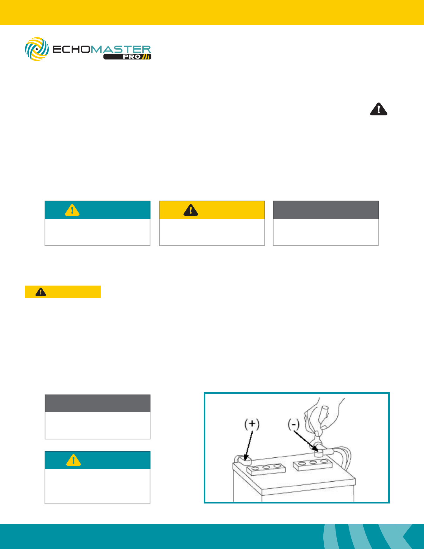
NOTE
Consult Vehicle owners guide
before disconnecting negative
battery cable
WARNING
DO NOT TOUCH the positive
terminal with any tool when
removing the negative battery
cable
Vehicle Preparation & Protection
Consult your vehicle owner’s manual to disconnect the battery. Do not disconnect ANY airbag connectors or
indicators. Doing so may result in activating a diagnostic code. These codes will require the dealer to perform
the reset procedure which may incur a reset fee. If you are unsure of any vehicle trim removal process consult
the OEM service manual.
Removing vehicle trim panels in extreme hot and/or cold climate could result in damage. Use care when
removing all vehicle trims. Using painter’s blue tape on the vehicle trim panels can help limit any scratches
and / or marring. Use a nylon trim panel removal tool whenever possible.
CAUTION
3
Installation Guide
3
tel - 1-800-477-2267
email - [email protected]
Illustrations are typical and may not match exact vehicle detail
FCTP-MB2503
Sprinter Tow Package
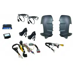
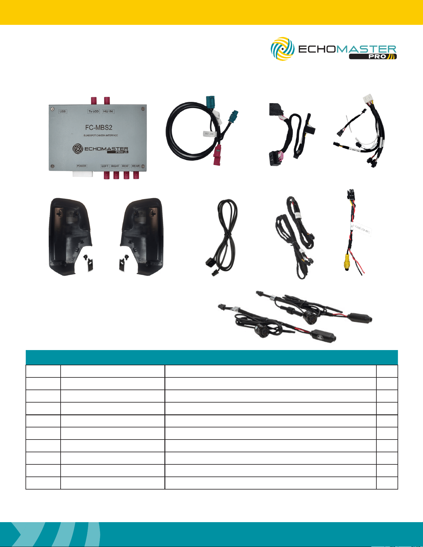
What’s in the box
Parts Description
FCTP-MB1903
Image Part Number Description Qty
1
FC-MBS2 Interface Module For 2025+ Mercedes Sprinter 1
2
FC-MBS2-LVDS-HAR LVDS Harness for FC-MBS2
1
3
NTG7-PWR-HAR Power / CAN Harness for FC-MBS2
1
4
FC-MBS2-HAR Power / Camera Harness for FC-MBS2
1
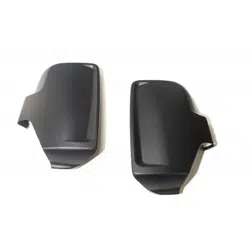
5
BSCM-MB1101v2 Side Mirror Cap Camera Mounts (L&R)
1
6
FC-MBS2-KEYPAD Keypad Tester for FC-MBS
1
7
CAM-EXT105-HAR 105” 4 Pin Camera Extension Harness
2
8
CAM-EXT4PRCA-HAR Front / Rear Camera RCA Adapter Harness
2
9
SVC-02 Side Camera w/ Power Supply
2
1 3
5 6 7 8
2 4
9
4
Installation Guide
4
tel - 1-800-477-2267
email - [email protected]
Illustrations are typical and may not match exact vehicle detail
FCTP-MB2503
Sprinter Tow Package
Setting the DipSwitches
1
ON
2 3 4 5 6 7 8
FC-MBS
BLINDSPOT CAMERA INTERFACE
LVDS
CAMERA POWER
1
ON
2 3 4
1
ON
2 3 4 5 6
1
ON
2 3 4
1
ON
2 3 4 5 6 7 8
1
ON
2 3 4 5 6 7 8
FC-MBS
BLINDSPOT CAMERA INTERFACE
LVDS
CAMERA POWER
1
ON
2 3 4
1
ON
2 3 4 5 6
1
ON
2 3 4
1
ON
2 3 4 5 6 7 8
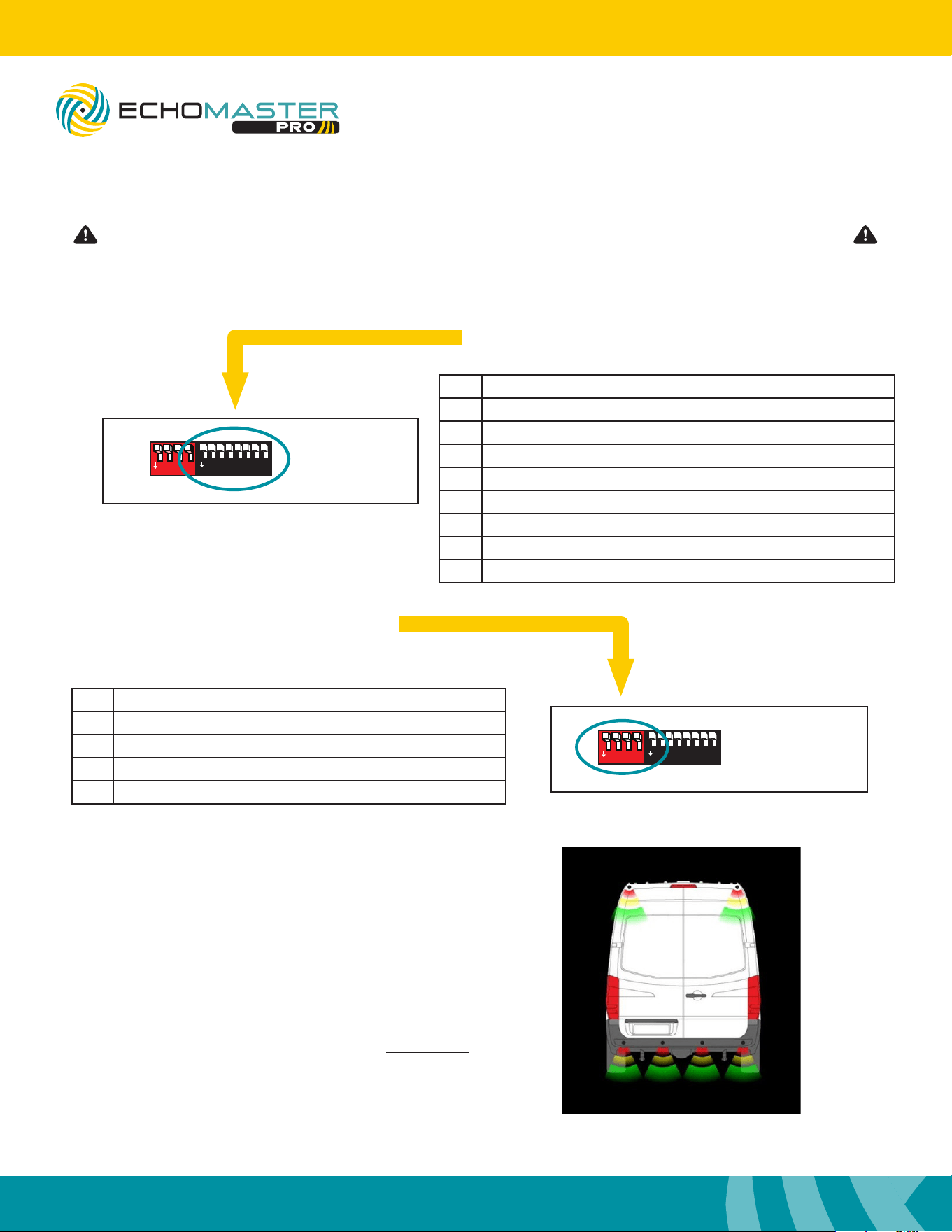
No. Function
1 Left Camera - On / Off
2 Right Camera - On / Off
3 Front Camera - On / Off
4 Reverse Camera - On / Off
5 Triggers - ON = Analog / OFF = CAN
6 Camera Type - ON = Digital / OFF = Analog
7 Front Camera After Reverse - ON / Off
8 MUST BE OFF
Side Black DipSwitch Settings
Side Red DipSwitch Settings
No. Function
1 *Sensor Bars on Reverse Image - ON / Off
2 MUST BE OFF
3 *Sensor Overlay - On / Off
4 MUST BE OFF
*Only Compatible when using EchoMaster 6 Sensor kits
Please be sure to set all DipSwitches before plugging the interface module into the vehicle.
When Red DIP switch #3 is in the ON position,
and the EchoMaster PS-6CRBP sensor kit is
connected to the harness, a vehicle overlay is
displayed on the right-hand side of the screen to
display the status of the reversing sensors while
the vehicle is in the reverse gear. The use of this
feature requires the use of an aftermarket reverse
camera connected to the camera input on the
module. The factory reverse camera CAN NOT be
used when using this feature.
5
Installation Guide
5
tel - 1-800-477-2267
email - [email protected]
Illustrations are typical and may not match exact vehicle detail
Step 1
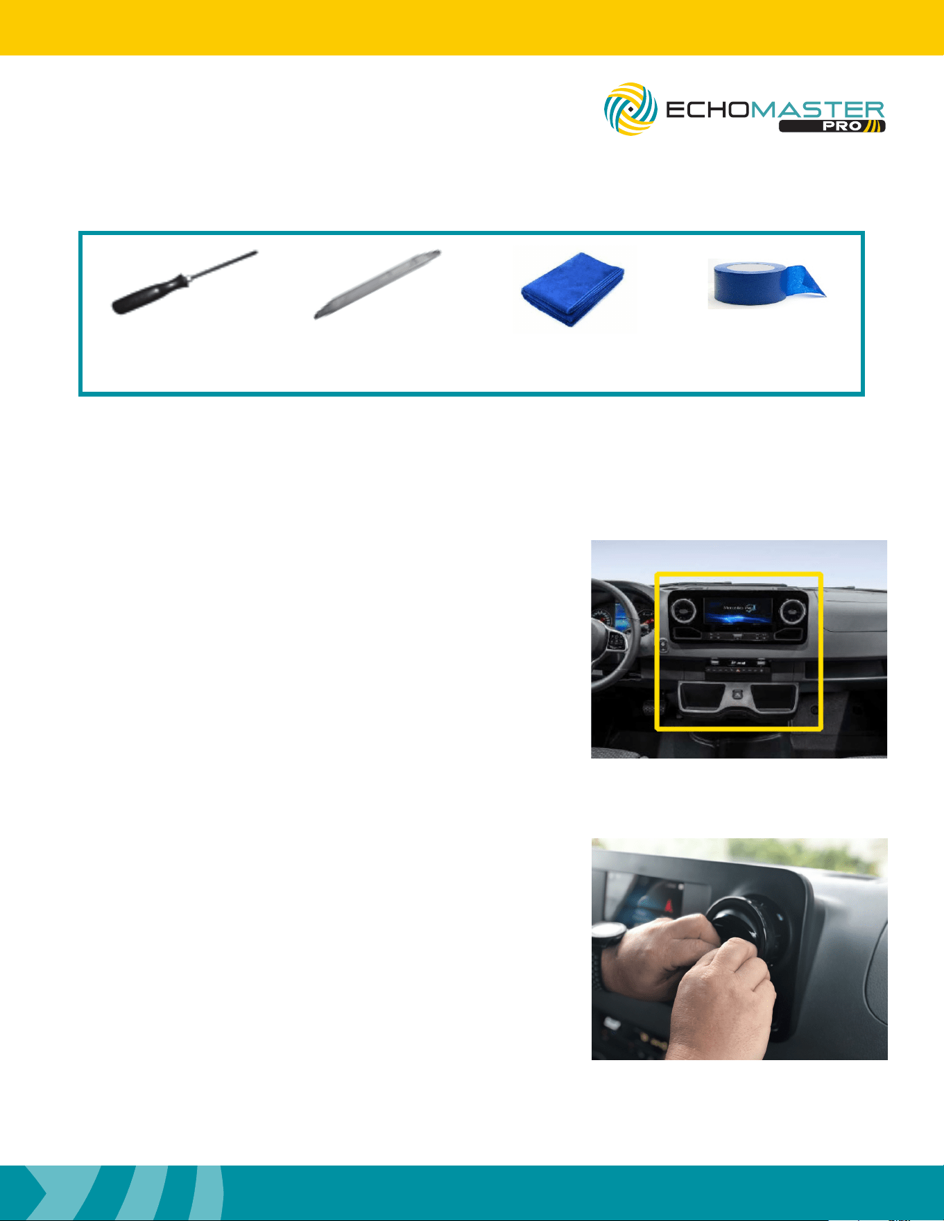
Carefully tape off the dash trim piece around the radio
display including the cup holders below the radio.
Dash Disassembly
Step 2
Carefully remove the HVAC vents from the dash by aiming
the vents all the way down and pulling on the HVAC vent
surrounds.
FCTP-MB2503
Sprinter Tow Package
Tools Required
T-20, T-30
Torx Drivers
Trim
Removal Tool
Towel Painters
Tape
6
Installation Guide
6
tel - 1-800-477-2267
email - [email protected]
Illustrations are typical and may not match exact vehicle detail
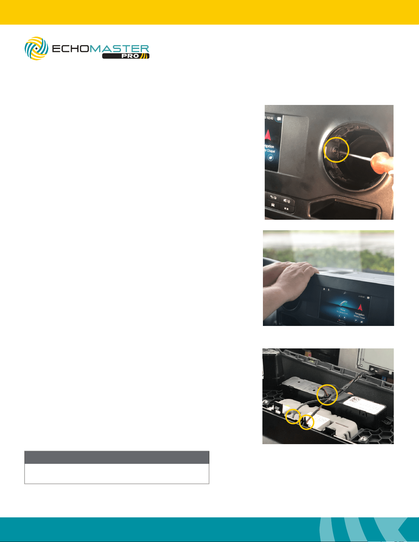
Step 3
Remove the two T20 Torx bolts, one behind each vent, that
were exposed by removing the vents.
Dash Disassembly (continued)
FCTP-MB2503
Sprinter Tow Package
Step 5
Remove the radio display by disconnecting the 3 connectors
and set it in a safe area to avoid damage.
Once the radio display is removed, place in safe area
to avoid damage.
NOTE
Step 4
Using both hands, pull at the upper corner of the dash
panel that houses the LCD screen from the dash.
7
Installation Guide
7
tel - 1-800-477-2267
email - [email protected]
Illustrations are typical and may not match exact vehicle detail
FCTP-MB2503
Sprinter Tow Package
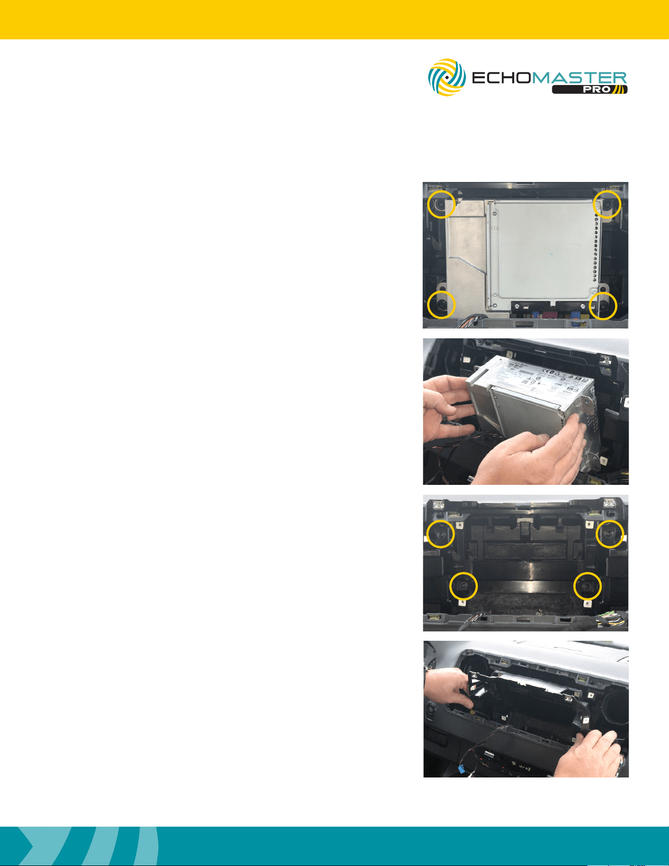
Step 6
Release the radio brain by removing the four T20 Torx bolts,
one at each corner, that were exposed by removing the dash
panel. Rest the radio brain on the lower dash.
Step 8
Remove the sub dash panel by tilting the top toward the rear
of the vehicle and lifting out of the dash.
Step 7
Remove the sub dash panel by removing the four T20 Torx
bolts, one at each corner, that were exposed by removing
the radio brain.
8
Installation Guide
8
tel - 1-800-477-2267
email - [email protected]
Illustrations are typical and may not match exact vehicle detail
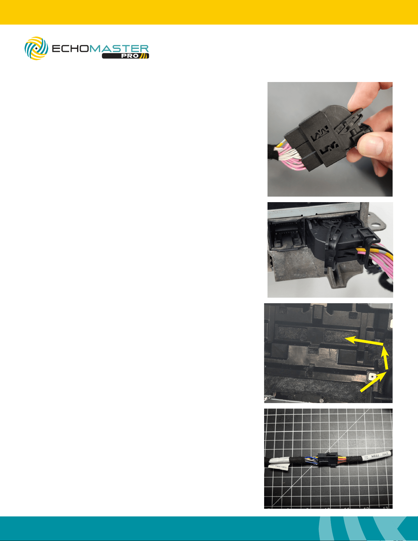
Step 1
Disconnect the 26pin Connector from the back side of the
radio.
Interface Connections
Step 2
Connect the NTG7 Power Cable’s T-harness section
to the vehicles 26pin connector and then to the radio’s
26pin connector.
FCTP-MB2503
Sprinter Tow Package
Step 3
Route the 10pin Molex connector from the NTG7 Power
Cable behind the plastic sub dash on the left side then
connect it to the mating 10pin Molex connector on the
harness labeled FC-MBS2-HAR.
9
Installation Guide
9
tel - 1-800-477-2267
email - [email protected]
Illustrations are typical and may not match exact vehicle detail
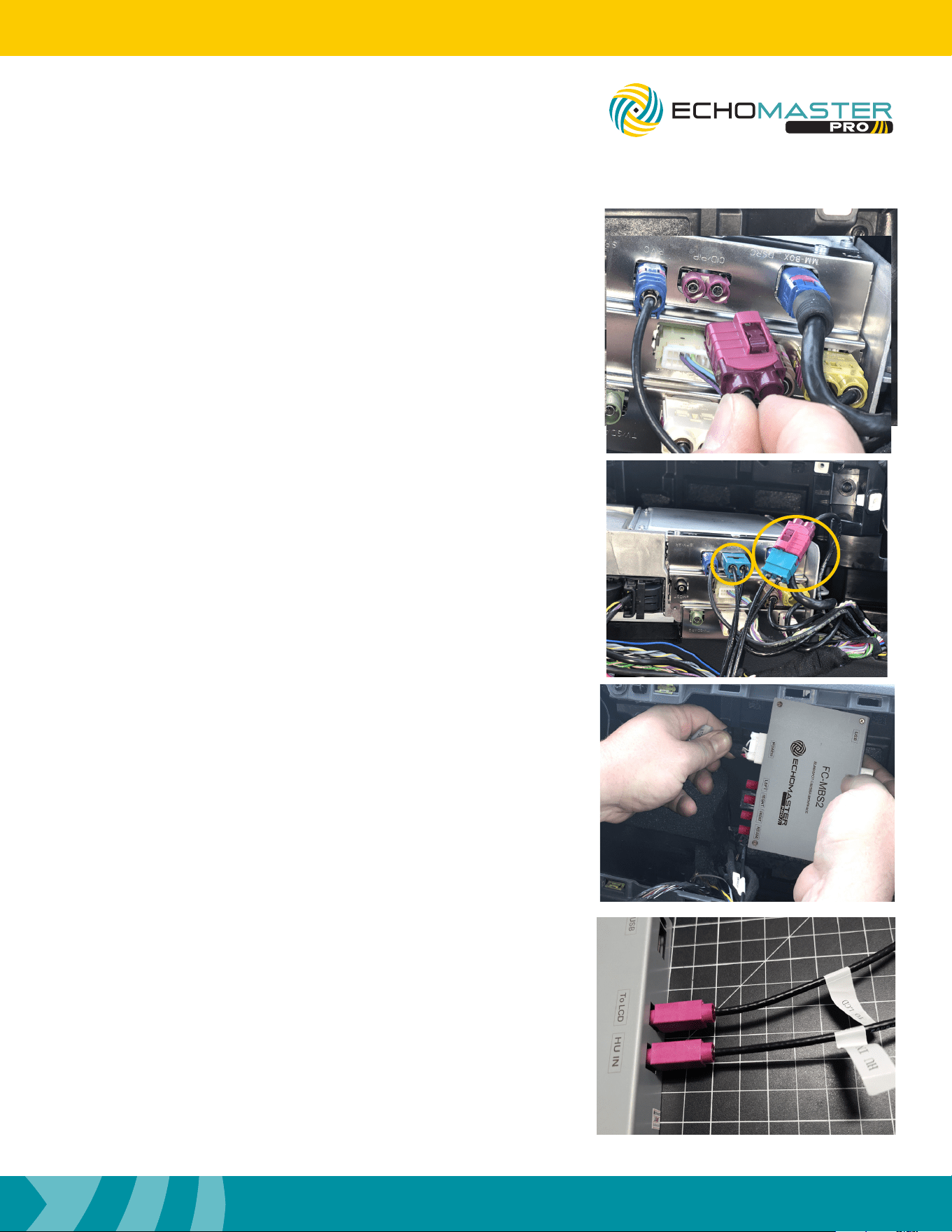
Step 5
Connect the Power/Camera harness and LVDS connectors
to the FC-MBS2 control module. Pay close attention to the
“HU IN” and “TO LCD” labels on the cables and make sure
they are connected correctly.
Step 4
Disconnect the LVDS cable from the radio brain, labeled
“CID/PIP”, and connect the EchoMaster LVDS cable inline
with the factory cable and then back into the radio.
FCTP-MB2503
Sprinter Tow Package
10
Installation Guide
10
tel - 1-800-477-2267
email - [email protected]
Illustrations are typical and may not match exact vehicle detail
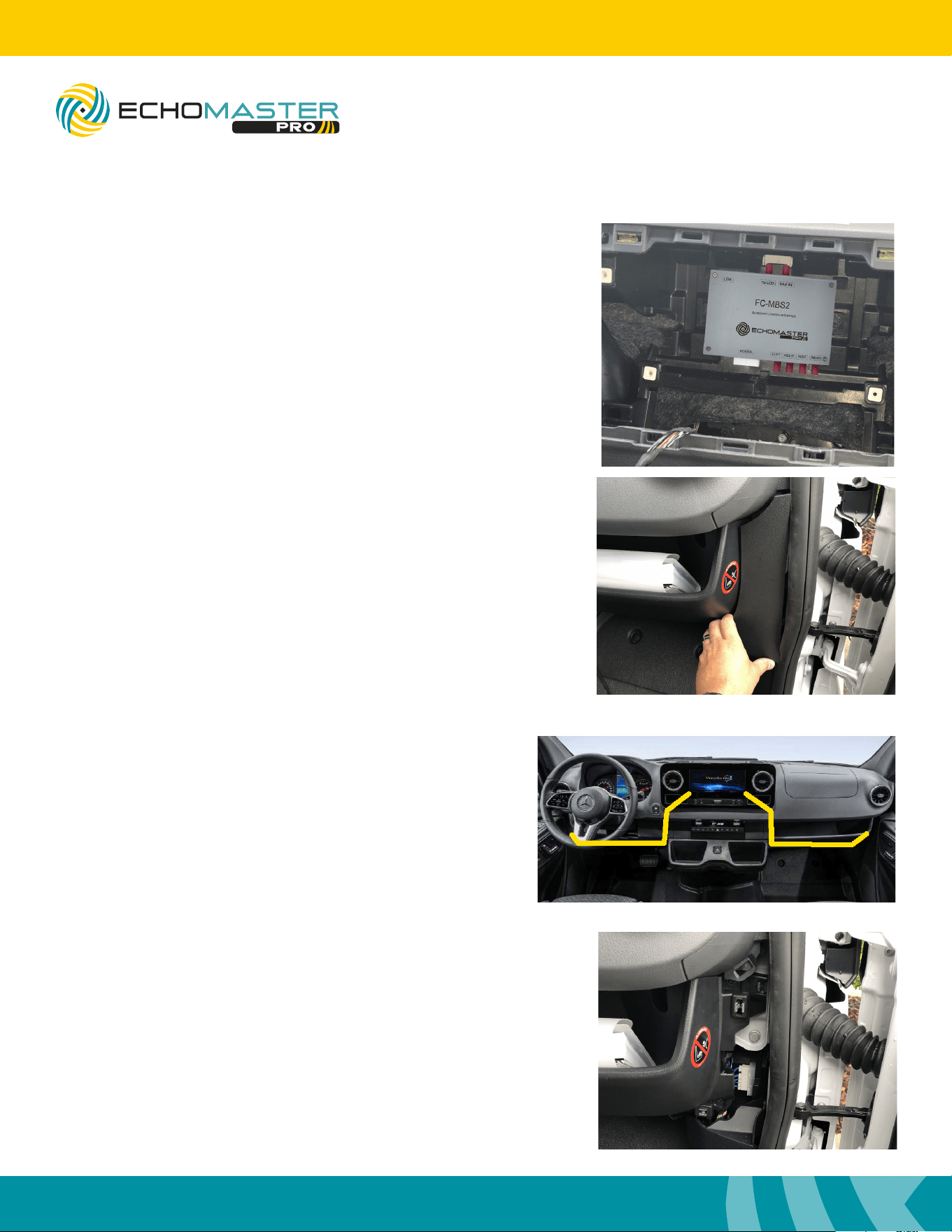
Step 6
Using a zip tie secure the module to the sub dash center
support.
Interface Connections (continued)
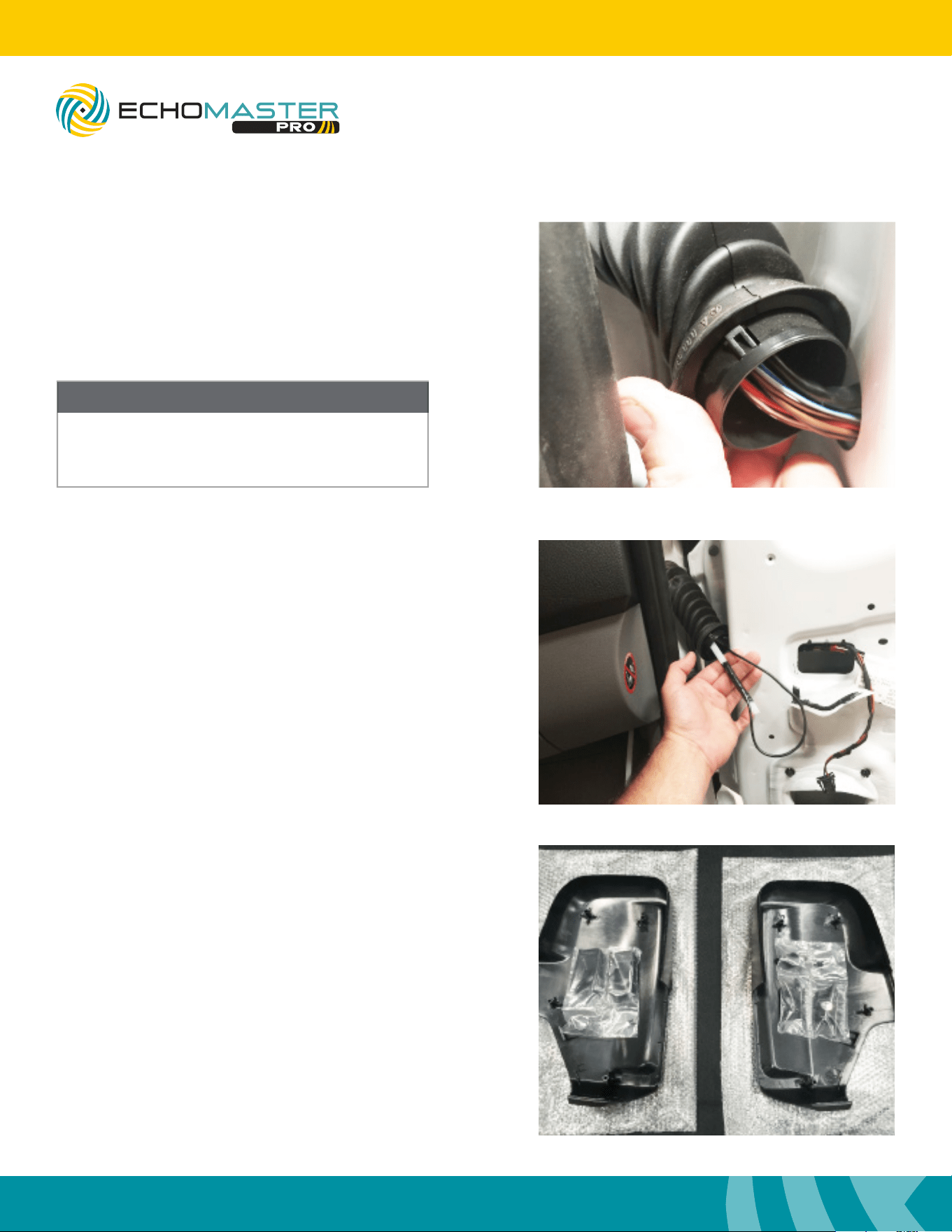
Step 7
Remove the access panels just below the dash by pulling
the door seal back and pulling the panels towards the
rear of the vehicle.
Step 8
Using a large cable tie or dash snake, route the
camera harnesses from behind the radio to where
you removed the access panel in step 8. Once the
camera extension cables are routed, connect the
radio side of the cable to the corresponding left /
right input on the modules camera harness.
Be sure when routing the cables, any and all moving
parts or sharp edges are avoided.
FCTP-MB2503
Sprinter Tow Package
11
Installation Guide
11
tel - 1-800-477-2267
email - [email protected]
Illustrations are typical and may not match exact vehicle detail
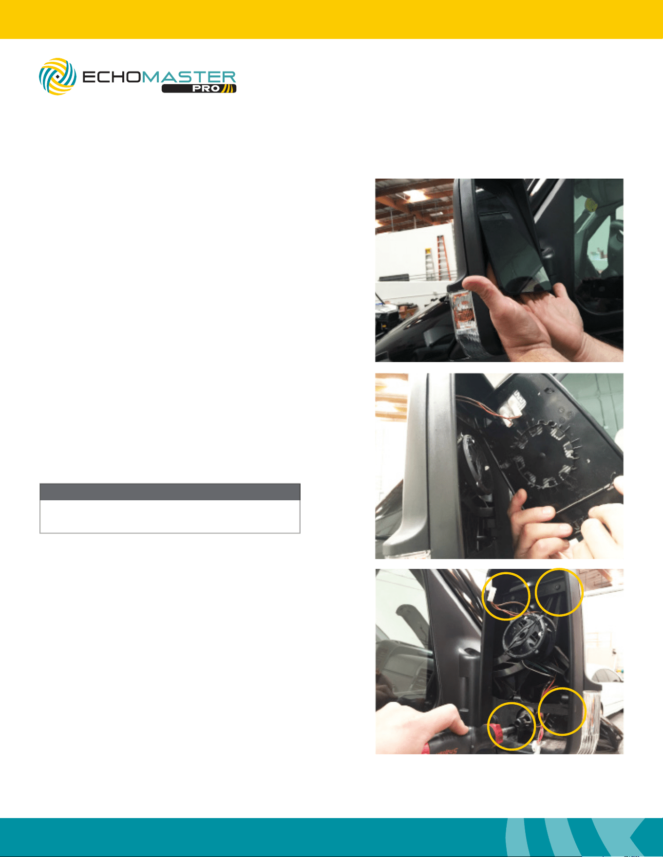
Mirror Disassembly
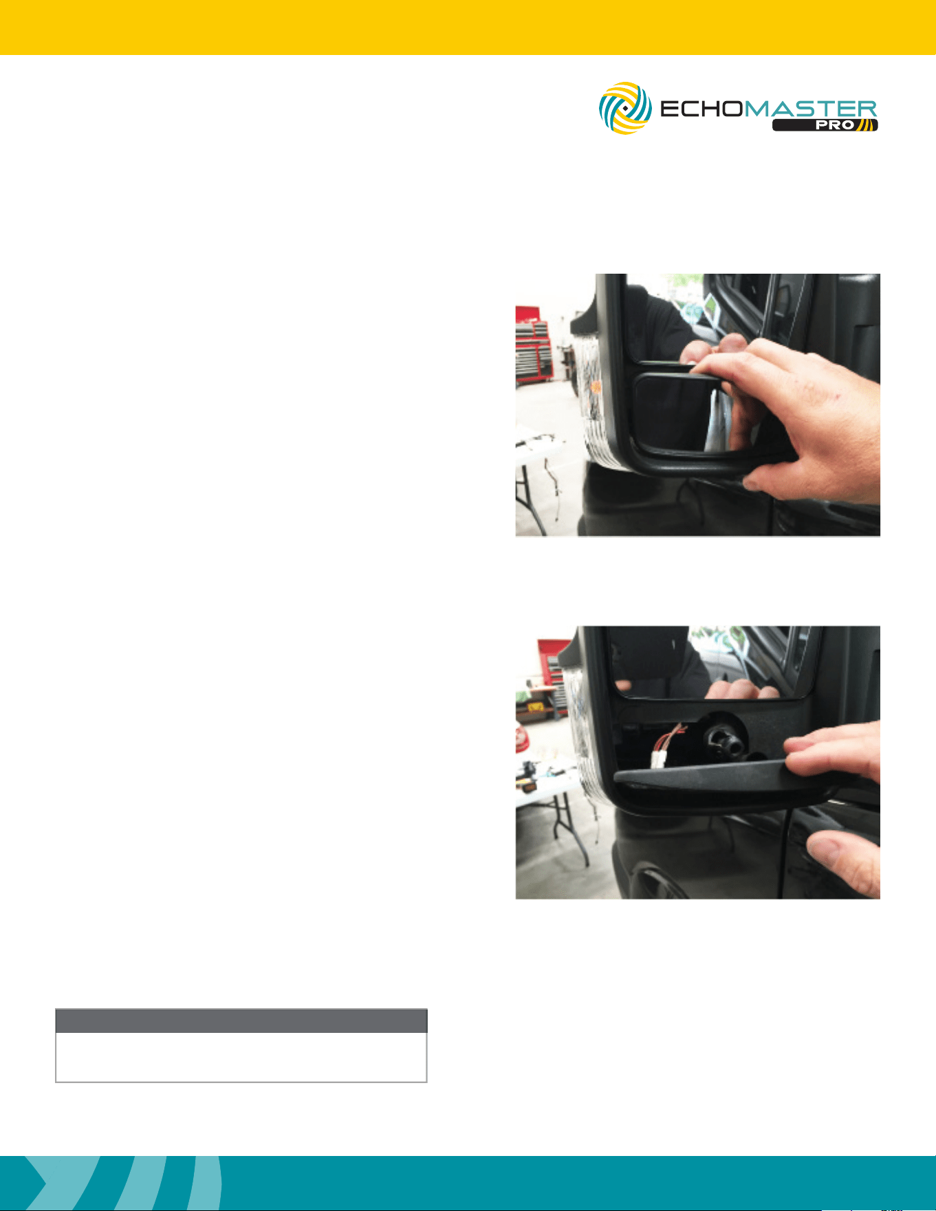
Step 1
Push the bottom of the top mirror glass in to gain
access to the lower mirror glass.
Using even pressure, pull the bottom mirror glass
off towards you. The mirror will pop off.
Step 2
Disconnect the defroster connector.
Not all models will have the defroster.
Once the mirror glass is removed, place in safe
place to avoid damage
NOTE
FCTP-MB2503
Sprinter Tow Package
12
Installation Guide
12
tel - 1-800-477-2267
email - [email protected]
Illustrations are typical and may not match exact vehicle detail
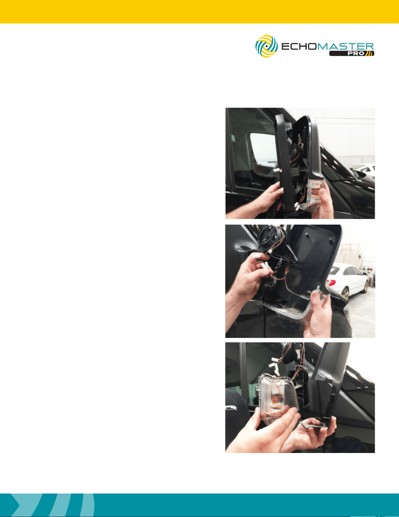
Step 3
Tilt the top mirror glass so you can place both hands up un-
der the glass to get to the center of the back of the glass.
Applying even pressure, pop the glass off.
Step 4
Disconnect the defroster connector.
Not all models will have the defroster.
Step 5
Remove the four Torx T20 screws around the mirror housing.
Mirror Disassembly (continued)
NOTE
Once the mirror glass is removed, place in safe
area to avoid damage
FCTP-MB2503
Sprinter Tow Package
13
Installation Guide
13
tel - 1-800-477-2267
email - [email protected]
Illustrations are typical and may not match exact vehicle detail
Step 6
Remove the outer trim ring.
Support the back cover while removing the outer trim ring.
Place in a safe area to avoid damage.
Step 7
Remove the back cover of the mirror housing.
Step 8
The turn signal indicator snaps off the back cover.
Place the back cover in a safe area to avoid damage.
FCTP-MB2503
Sprinter Tow Package
14
Installation Guide
14
tel - 1-800-477-2267
email - [email protected]
Illustrations are typical and may not match exact vehicle detail
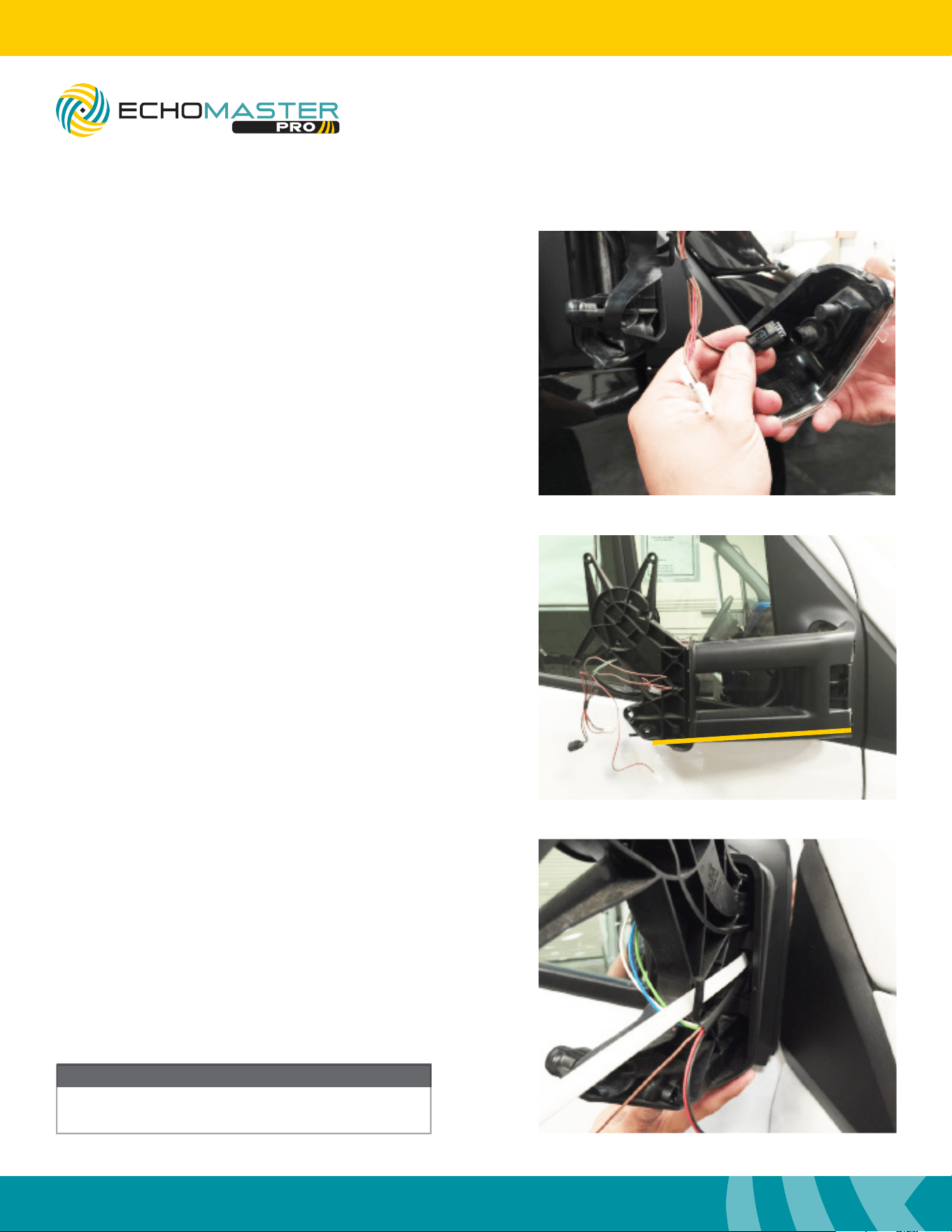
Step 9
Disconnect the turn signal indicator.
Place the turn signal indicator in a safe area
to avoid damage.
Cable Routing
Mirror Disassembly (continued)
NOTE
Removing the mirror assembly is not absolutely
necessary but makes the installation easier.
FCTP-MB2503
Sprinter Tow Package
Step 1
For the tow mirror, fold the arm in towards the door to
gain access to the inner hinge area. Feed a long wire tie
or similar sh tool through the lower outside portion of
the tow mirror arm. Tape the camera cable to the end of
the wire tie you are using to feed the wire through. It may
be necessary to split the plastic pieces at the bottom of
the arm to allow the connector to pass through.
Step 2
Feed a long wire tie or similar sh tool through the mirror
where the factory wires come through. Tape the camera
cable to the end of the wire tie you are using to feed the
wire through.
Non-Tow Mirror
Tow Mirror
15
Installation Guide
15
tel - 1-800-477-2267
email - [email protected]
Illustrations are typical and may not match exact vehicle detail
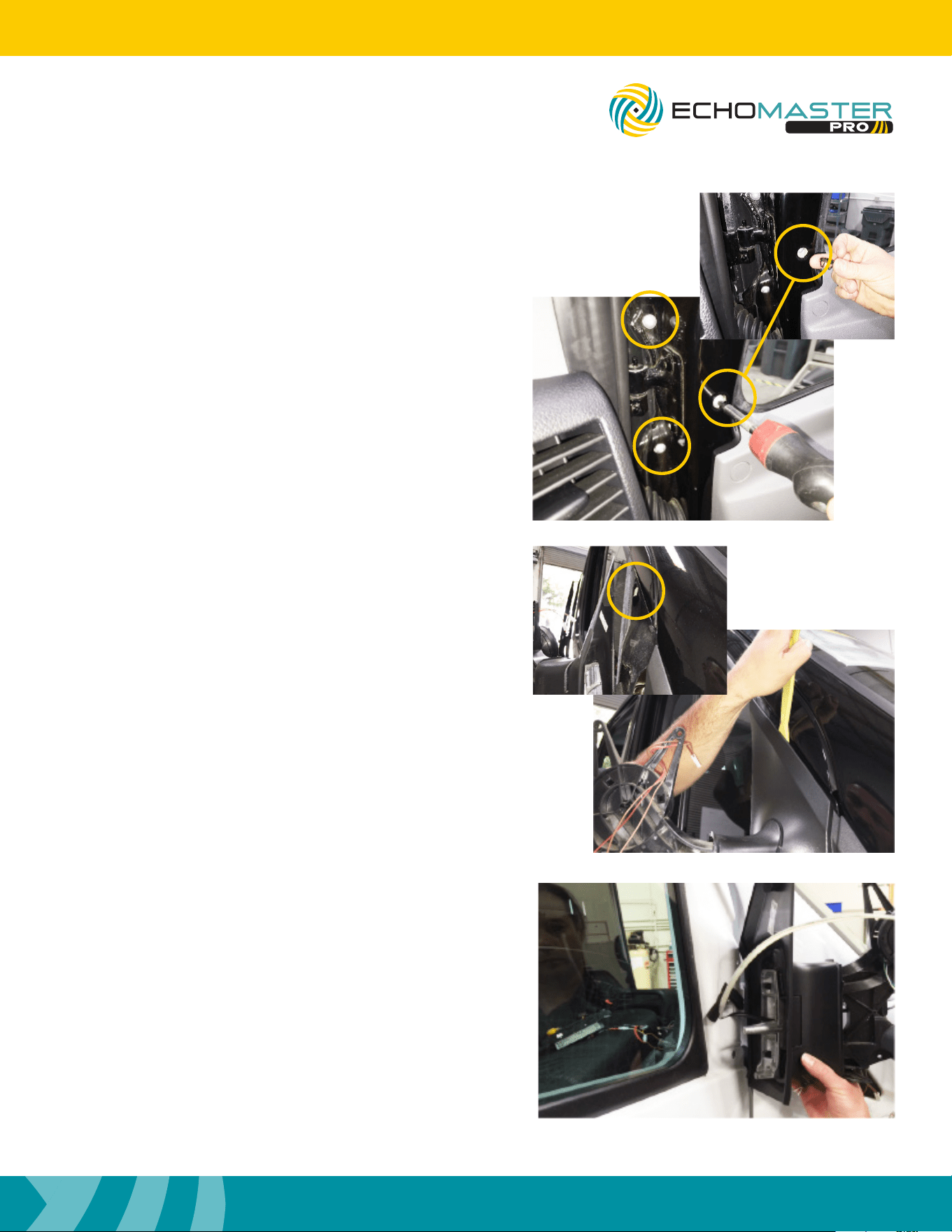
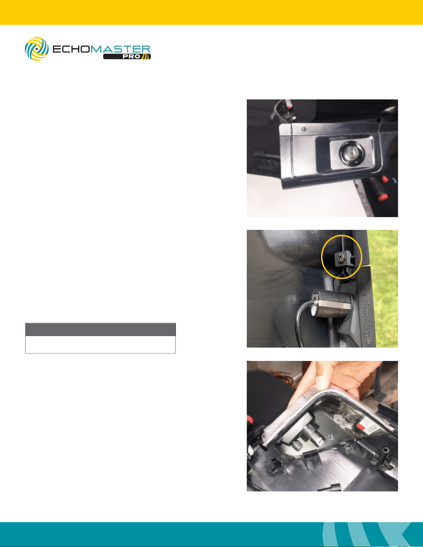
Step 3
Remove the three Torx T30 screws holding the
mirror to the door of the truck.
One of the Torx T30 screws has a small cap
covering it. Use something slim to pry the cover
off to access the screw.
The mirror arm will still be held on with a clip on
the outside.
Step 4
Using a nylon pry tool, insert it (approximately as
shown - above the hook) then pull it out and push
the mirror assembly up to disengage.
Step 5
Feed a long wire tie or similar sh tool through the door
to where the factory wires come through the boot.
FCTP-MB2503
Sprinter Tow Package
16
Installation Guide
16
tel - 1-800-477-2267
email - [email protected]
Illustrations are typical and may not match exact vehicle detail
Step 6
Unsnap the door boot on the door side, and feed the
wire tie through with the camera cable taped to the
end. It is not necessary to remove the boot from the
black snap ring.
Only the door side of the boot needs to be removed.
Step 7
Feed a long wire tie or dash snake tool through the boot
then into the vehicle as shown. Reach in behind the access
panel to guide the wire tie if needed.
The boot does not need to be removed from the vehicle
side.
Once inside the vehicle connect the camera cable to the
power supply and then to the camera extension cable
that was ran during step 8 on page 10. Secure the power
supply and any excess wire using a wire tie.
Cable Routing (continued)
NOTE
Once the cable is routed into the door jamb
reinstall the three Torx T30 screws that hold the
mirror frame on to the vehicle to avoid damage.
FCTP-MB2503
Sprinter Tow Package
Mirror Assembly
Step 1
With the cables routed, you can assemble the mirror caps
with the cameras.
17
Installation Guide
17
tel - 1-800-477-2267
email - [email protected]
Illustrations are typical and may not match exact vehicle detail
FCTP-MB2503
Sprinter Tow Package
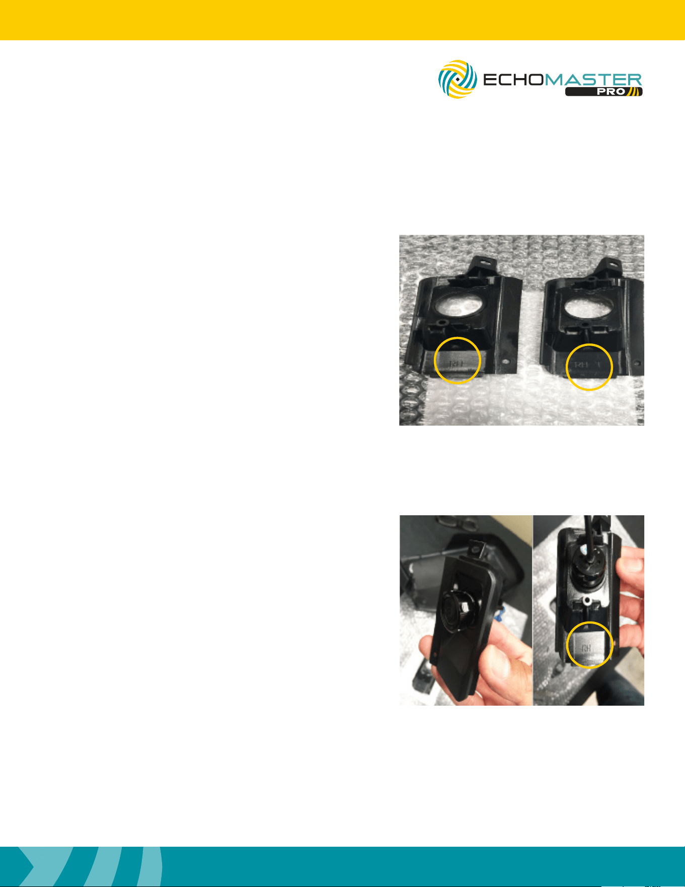
Step 2
There are two sets of camera inserts per side.
RH Right hand side
RH-T Right hand side towing
LH Left hand side
LH-T Left hand side towing
The towing inserts are for the mirrors that extend out
farther from the vehicle.
Step 3
Select the inserts you are going to be installing.
There is a at notch on the camera; this notch will perfectly
align the camera.
Mirror Assembly (continued)
18
Installation Guide
18
tel - 1-800-477-2267
email - [email protected]
Illustrations are typical and may not match exact vehicle detail
FCTP-MB2503
Sprinter Tow Package
Step 4
When installing the camera insert on to the mirror
caps, the locating tab will line up with a small hole
on the front of the camera insert.
Step 5
Once the camera insert is installed in place,
use a number 1 Phillips screwdriver to mount
the camera insert.
Step 6
Once the camera insert is installed, snap the turn
signal in place. Reinstall the mirror caps, in the
reverse order they were removed.
Make sure all connections in the mirror are fully
seated and secure when reinstalling everything.
NOTE
DO NOT OVER TIGHTEN
Mirror Assembly (continued)
19
Installation Guide
19
tel - 1-800-477-2267
email - [email protected]
Illustrations are typical and may not match exact vehicle detail
FCTP-MB2503
Sprinter Tow Package
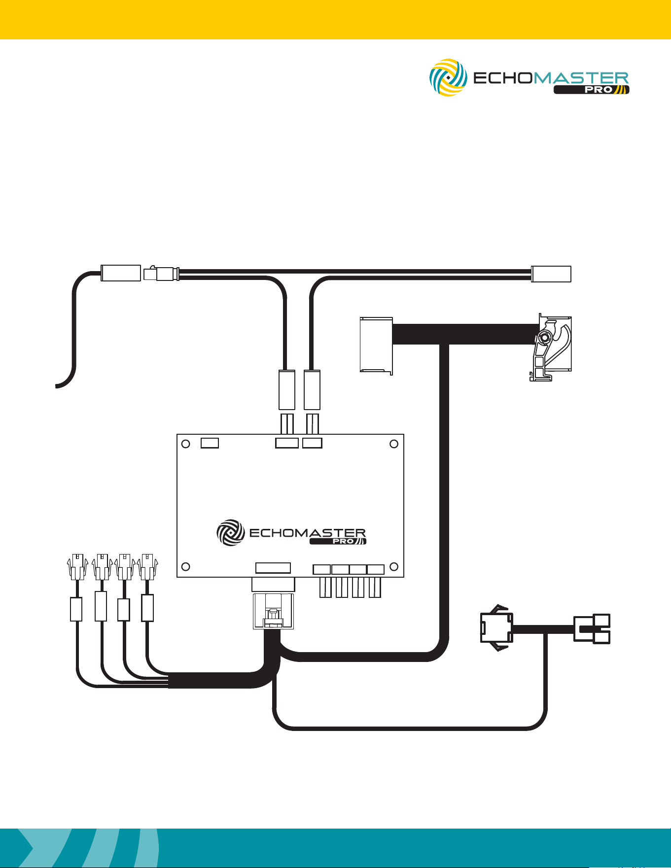
Wiring Diagram Overview
FRONT
LEFT
RIGHT
To Radio
To LCDUSB HU IN
POWER
REAR
To Screen
FC-MBS2
BLINDSPOT CAMERA INTERFACE
LEFT RIGHT FRONT REAR
To EchoMaster
Rear Sensor Kit

20
Installation Guide
20
tel - 1-800-477-2267
email - [email protected]
Illustrations are typical and may not match exact vehicle detail
FCTP-MB2503
Sprinter Tow Package
Testing
Reconnect the three connectors to the dash panel that were removed on page 6, step 5.
Reconnect the negative battery cable.
Turn the ignition switch to ON, when the display of the unit comes on and is done with the boot up sequence,
test the system for functionality.
Activate the right turn signal. Verify the right camera is displaying on the radio’s screen.
Activate the left turn signal. Verify the left camera is displaying on the radio’s screen.
Place your foot on the brake and place the vehicle in reverse. The rear camera will display on the screen.
Place the vehicle back in park to go to back to the main display.
It is also possible to cycle through the inputs / cameras using the Keypad Tester included in the box. When
using the keypad tester, the camera label (left, right, front, rear) will be overlaid in the top left corner of the
screen to help identify which camera is being displayed. To use, press and release the button, the rst camera
in the rotation will be displayed. Press and release the button again to change to the next camera. Once the
camera rotation has nished, pressing the button again will exit camera mode and return back to the main
display
Once proper operation has been conrmed, ensure all factory components are in working order (radios touch
screen, radio controls, etc.) Once proper operation has been conrmed it is now time to reassemble the
vehicle.

21
Installation Guide
21
tel - 1-800-477-2267
email - [email protected]
Illustrations are typical and may not match exact vehicle detail
FCTP-MB2503
Sprinter Tow Package
Notes:

AGREEMENT: End user agrees to use this product in compliance with the instructions and terms of use above and with
all State and Federal laws. EchoMaster provides instructions and safety warnings with respect to this product and
disclaims all liability for any use not in conformity with those instructions or other misuse of its product. If you do not agree,
please discontinue use immediately and contact EchoMaster. This product is intended for off-road use and passenger
use only.
email - [email protected]
tel - 1-800-477-2267
9620 Executive Center Drive N, Suite 200, St Petersburg, Florida 33702
EchoMaster is a Power Brand of Stinger.
EchoMaster.com
REV. 090825