

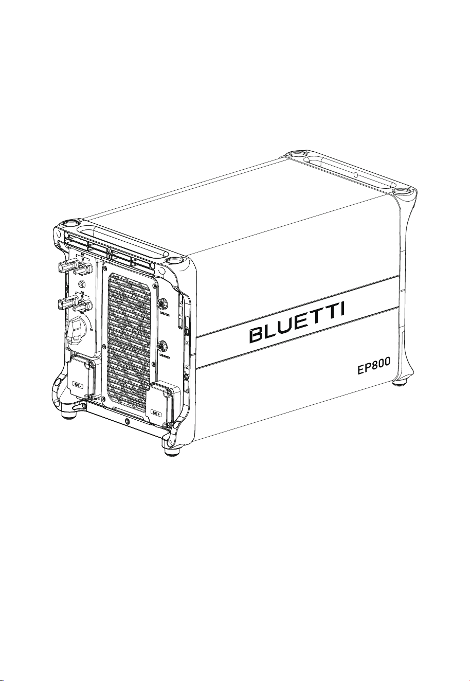
E
P800
Home Energy Storage System
User Manual V2.4
Please Read This Manual Before Use And Follow Its Guidance.
Keep This Manual For Future Reference.
Thank You!
Thank you for making BLUETTI a part of your family.
From the very beginning, BLUETTI has tried to stay true to a sustainable future
through green energy storage solutions while delivering an exceptional
eco-friendly experience for our homes and our world.
That's why BLUETTI makes its presence in 100+ countries and is trusted by
millions of customers across the globe.

Instruction
Copyright © ShenzhenPowerOakNewenerCo., Ltd. All rights reserved.
No part of this document may be reproduced or transmitted in any form or by any
means without the prior written consent of ShenzhenPowerOakNewenerCo.,
Ltd.
Notice
BLUETTI's products, services, and features are subject to the agreed-upon terms
and conditions during purchase. Please note that some products, services, or
features described in this manual may not be available under your purchase
contract. Unless otherwise specified in the contract, BLUETTI makes no repre-
sentations or warranties of any kind, express or implied, with respect to the
contents of this manual.
The contents of this manual are subject to change without notice. Please get
the latest version from: https://www.bluettipower.com/pages/user-guides
If you have any questions or concerns about this manual, please contact
BLUETTI support for further assistance.
ShenzhenPowerOakNewenerCo., Ltd.
F19, BLD No.1, Kaidaer, Tongsha RD No.168, Xili street, Nanshan, Shenzhen, China
Web: https://www.bluettipower.com
About the Manual
Purpose
This user manual describes the installation, electrical connection, commission-
ing, maintenance and troubleshooting of EP800 Home Energy Storage System
(hereinafter referred to as EP800). Please read and understand all instructions
in this manual before use.
Target Audience
This manual is intended for:
• Installation, operation, and maintenance technicians
• End-user
Symbol Conventions
This manual uses the following symbols to highlight important information:
Danger
Warning
Caution
Attention
Instruction
It indicates a hazardous situation which, if not avoided, will
result in death or serious injury.
It indicates a hazardous situation which, if not avoided, could
result in death or serious injury.
It indicates a hazardous situation which, if not avoided, could
result in minor or moderate injury.
It indicates a potentially hazardous situation which, if not
avoided, could cause substantial damage to property and the
environment.
It contains important additional information as well as useful
tips for safe, efficient and hassle-free operation of the EP800
energy system.

Safety Guideline
EP800 Home Energy Storage System
Introduction
Working mode
EP800 Home Energy Storage Inverter
Introduction
Inverter Overview
Interfaces
LED Indicator
Buzzer Alarm
Inverter Cables
B500 Battery
Introduction
Overview
Interfaces
LED Indicators
Battery Cables
IoT Controller
System Installation
Installation Procedure
Preparation
Installation Requirements
Stacking the Units
Install the IoT controller
Electrical Connection
System Check
System Maintenance
System Disposal
Specifications
Troubleshooting
FAQs (Frequently Asked Questions)
FCC Warning
Contents
1
2
2.1
2.2
3
3.1
3.2
3.3
3.4
3.5
3.6
4
4.1
4.2
4.3
4.4
4.5
5
6
6.1
6.2
6.3
6.4
6.5
6.6
7
8
9
10
11
12
13
06
18
18
19
23
23
23
24
27
27
28
29
29
29
30
31
31
32
35
35
36
43
45
47
49
61
63
64
65
68
73
78

JUST POWER ON06
1. Safety Guideline
1.1 Safety Instructions
Read this manual for instructions on the proper use and safety information for the unit.
Pay attentionto the "Instruction", "Caution", "Warning" and "Danger" symbols in this
manual, and follow theinstructions carefully to avoid injury or damage.
The safety instructions provided herein are for illustrative purposes that include but are not
limited to those listed in this manual. Actual operation shall comply with all applicable
safety standards. If you have any questions, feel free to contact BLUETTI support or your
local BLUETTI dealers.
To ensure a safe and reliable operation, it’s crucial to carefully observe and adhere to
the following conditions:
• Always operate or store the equipment in the conditions specified in this manual.
• The installation and ambient conditions must comply with the regulations in the
relevant international, national or regional standards.
• Avoid unauthorized disassembly, equipment replacement, or modification of
software codes.
BLUETTI shall not be liable for damages resulting from the following circumstances:
• Force majeure events such as earthquakes, fires, storms, floods, or mudslides.
• Damages caused by improper handling and installation that do not meet the
requirements outlined in the manual.
• Damages resulting from inadequate storage conditions as specified in the manual.
• Hardware or data damage caused by customer negligence, improper operation, or
intentional actions.
• System damage caused by third parties or customers.
• Adjustments, changes, or removal of labels in violation of this manual.
Attention
This product is not intended for use with devices that have
high-performance requirements for UPS (Uninterruptible Power
Supply), including but not limited to data servers, workstations,
medical equipment, and similar devices. Our company shall not be
liable for any data loss, equipment damage, or personal injury
resulting from the violation of this requirement.

JUST POWER ON 07
1.2 General Requirements
•
Do not install, use and maintain the equipment in adverse weather conditions
such as lightning, rain, snow and strong breezes (including but not limited to
handling and operating the equipment, plugging and unplugging signal connec-
tions to outdoor facilities, working at height, outdoor installations, etc.).
• Always turn off the power sourcebeforestartingany electrical work.
• Do not clean the equipment with water.
• Do not disassemble,modify, tamper with or repairthe equipment on your own.
• Regularly inspect the equipment and its accessories for damage or deterioration.
• Use a tester to check for the presence of dangerous voltage before touching any
conductor or terminal.
• If the equipment’s exterior sustains minor scratches during transportation or use,
be aware that these do not impact the equipment’s normal operation.
• If the equipment catches fire, your personal safety is paramount. If it's safe to do so,
promptly disconnect power at the main distribution box and use a carbon dioxide
(CO2), FM-200, or ABC dry powder fire extinguisher to suppress the fire.
• In case of fire, EVACUATE the building or affected area immediately. Activate the
closest FIRE ALARM system and CALL your local emergency phone number.
• Use genuine cables and accessories provided by BLUETTI.
• Keep the equipment away from heat sources or high temperatures, and do not
expose it to direct sunlight.
• Do not store the equipment with flammable or explosive materials.
• Make sure the area where you are using the equipment is well ventilated and spacious.
• Do not block or cover the vents of the equipment.
• Use the equipment for its intended purpose and avoid stacking objects on top of it
during storage or use.
• Do not move the equipment during operation as the vibrations and shocks
associated with movement may cause damage to the internal hardware.
Danger
Follow these guidelines for proper operation.

Instruction
JUST POWER ON08
1.4 Installation Safety
Danger
Avoid working with live electrical components.
Before installation, double check the equipment for any signs of
damage or defects to minimize potential risks.
Make sure that the equipment and all associated switches are in the
"OFF" position to prevent electric shock.
Do not touch any terminal while the equipment is running, as it may
pose a risk of electric shock.
1.3 Personnel Requirements
•
The installation, commissioning and maintenance should only be performed by
trained professionals who obtain an electrical certification, follow proper safety
precautions and operating practices.
• To operate BLUETTI equipment, professionals must possess the necessary
qualifications and electrical certifications required by local regulatory authorities.
The transportation, wiring and maintenance shall comply with all
applicable laws, regulations and standards.
User-provided materials and tools required shall meet the require-
ments specified in applicable laws, regulations and relevant
standards.
• In case of malfunction, turn off the equipment immediately and contact BLUETTI
support or your local BLUETTI dealers if this manual cannot adequately explain the
malfunction to you.
• Do not place the equipment on an unstable or inclined surface.
• Do not insert foreign objects into any port and vent of the equipment.
• Keep the system out of the reach of children and pets.
• Do not install the system in areas prone to water accumulation.
Comply with applicable laws and regulations.
•
•
•
•
•
•
JUST POWER ON 09
Warning
The installation should only be performed by qualified professionals
or trained personnel.
All cables should be securely connected and meet required
specifications.
Do not touch the equipment, as the shell may become hot and pose
a risk of burns when it’s running.
Attention
Handle the equipment and accessories with care during loading,
unloading and transportation.
1.4.1 General Requirements
•
Before starting any work, turn off and isolate all electricity to the property at the
main panel.
• Take measures to prevent the electricity from turning back on while working, such
as a safety tag and lockout.
• Test the circuit's voltage before proceeding to verify that the course is off.
• After installing the equipment, remove the idle package materials from the site
such as cartons, foam, plastic, nylon ties, etc.
• Keep people other than the installation technicians away from the energy storage
system.
• When handling equipment and accessories, pack them in their original packaging
or other materials to protect them from impact.
• Seal all the wiring ports with fireproof and water-proof materials to prevent
possible electric shock or other risks.
• It’s prohibited to alter, damage or cover the marking and nameplate of any part of
the system.
• Check and make sure all safe guards, including screws and waterproof rings, are in
place and properly tightened.
• Position the system on the flat surface and firmly secure it to a wall or other solid objects.
• Use a non-abrasive cloth to clean the equipment and accessories. Do not use water
or harsh chemicals.
• Do not make changes or modifications to the equipment’s structure, installation
sequence, etc.
•
•
•

JUST POWER ON10
1.5 Battery Safety
1.5.1 Statement
BLUETTI shall not be liable for equipment abnormality component damage,
personal injury property loss or other damage caused by the following reasons:
• Failure to promptly charge the battery after installation and system connection, leading
to over-discharge and subsequent damage.
• Inadequate maintenance as instructed in the user manual, includes irregular charging,
improper capacity expansion, or prolonged periods of incomplete charging and frequent
over-discharging of the battery. If you need expansion, please contact BLUETTI support
within 6 months of installation. Do not attempt this on your own.
• Failure to charge the battery as required during storage, resulting in capacity loss or
irreparable damage.
• Improper operation or connection errors causing battery short-circuits, damage, drops, or
leaks.
• Battery damage caused by operating conditions or external power parameters that do
not meet environmental requirements.
1.4.2 Anti-static Requirements
•
Wear or use personal protective equipment (PPE) or clothing that is appropriate for
the work; this may include items such as safety glasses or goggles, or a face shield
(with safety glasses or goggles), hearing protection, dust mask, gloves, anti-static
bracelet, safety boots or shoes, or rubber boots.
• If you use an anti-static bracelet for electrical connections, make sure the bracelet
is properly grounded.
1.4.3 Drilling Requirements
When drilling holes in the wall or on the ground, the following safety measures
should be considered.
• Wear goggles and protective gloves at all times.
• Shield and protect the equipment to prevent debris from falling into it and remove
all debris after drilling.
• Drill holes on the unit are forbidden, as this may damage the equipment's electro-
magnetic shielding performance. The metal shavings may cause short circuits on
the circuit board.

JUST POWER ON 11
1.5.3 General Requirements
•
Do not expose the battery to high temperatures or around heat sources, such as
sunlight, fire, transformers and heaters. If the battery overheats, it may cause a fire.
• To avoid leakage, overheating or fire, do not disassemble, modify or damage the
battery. For example, do not insert foreign objects into the battery or place the
battery in water or other liquids.
• If any part of the battery is immersed in water, do not touch the battery to avoid
electric shock. Please contact the battery recycling company for handling.
• Do not short-circuit the battery terminals. A short circuit can cause a fire.
• Never use damaged batteries or components. Improper use or misuse of
damaged batteries or components can damage your device or injure yourself as a
result of battery fluid leakage, fire, overheating, or explosion.
• Do not perform welding or grinding work around the battery to prevent fire
caused by sparks or arcs.
• Do not store damaged batteries near undamaged ones, as damaged batteries
may leak flammable liquid or gas. Only qualified professional or trained personnel
is allowed to approach damaged batteries.
• The fire hazard of lithium-ion battery energy storage system is high. Before
handling batteries, consider the following risks:
(a)Battery thermal runaway may produce flammable and harmful gases such as
CO and HF. Vapors from burning batteries may irritate eyes, skin and throat.
(b)The concentration of flammable gases from battery thermal runaway may lead
to deflagration and explosion.
• Users or third parties using the battery in ways not specified in the user manual, including
using batteries from other brands, using BLUETTI batteries with different rated capacities,
or mixing the specified batteries with the aforementioned types.
1.5.2 Installation Requirements
•
Do not use batteries with compromised packaging. Make sure the battery switch is
in the OFF position.
• Tighten the screws securely and conduct regular checks.
• Prevent the positive and negative terminals of the battery from touching each
other or any metal objects to avoid heat generation or electrolyte leakage.
• After installing the equipment, remove unused packing materials such as foam,
carton, plastic and excess cables from the equipment area.

JUST POWER ON12
Danger
In case of fire, power off the system if it is safe to do so.
Use carbon dioxide, FM-200, or ABC dry powder fire extinguisher.
Remind firefighters to avoid contact with components carrying
dangerous voltage to prevent the risk of electric shock.
Overheating may cause the battery to deform and leak corrosive
electrolytes or toxic gas. Keep away from batteries to avoid skin
irritation and chemical burns.
(c)The battery electrolyte is flammable, toxic and volatile.
• Avoid contact w
ith spilled liquid or gas if the battery leaks chemicals or odors. Do
not approach the battery and contact a professional for disposal. Professionals
must wear goggles, rubber gloves, gas masks and protective clothing.
• Electrolyte is corrosive and can cause irritation and chemical burns. If you come
into direct contact with battery electrolyte, do the following:
(a)Inhalation of Vapors: Evacuate contaminated area, get fresh air immediately,
and seek medical attention.
(b)Eye Contact: Immediately flush eyes with water for at least 15 minutes, do not
rub eyes, and seek medical attention immediately.
(c)Skin Contact: Immediately wash the infected area with soap and water and
seek medical attention immediately.
(d)Ingestion: Seek medical attention immediately.
• Use the battery within the temperature range specified in this manual.
• Do not expose the battery to humidity or corrosives, as this may cause the battery
to rust, corrode and leak chemicals.
• Do not turn the battery upside down or tilt it.
• Do not ignore warning signs on parts or products made by the manufacturer.
Fire Emergency Measures
•
•
•
•
JUST POWER ON 13
1.5.4 Battery Disposal
•
Safely and carefully disposeofused batteries by the provisions of local laws and
regulations. Avoid treating batteries as regular household waste, as improper
disposal can lead to environmental pollution.
• If you find a leaking or damaged battery pack, contact us immediately or an
authorized battery recycling partner for expert assistance.
• If the battery pack reaches the end of its lifespan, please contact the battery
recycling company for further assistance.
• To maintain battery integrity, do not expose used batteries to high temperatures or
direct sunlight.
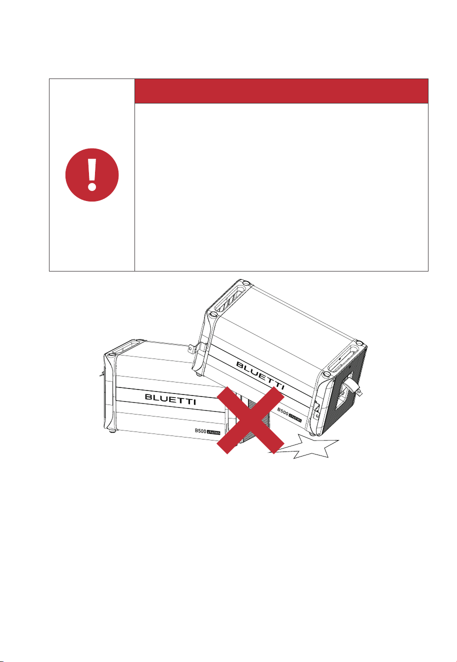
Danger
If the battery pack is dropped, violently impacted or tilted during
installation, internal damage may occur. So do not use such battery
packs to avoid safety risks such as battery leakage and electric shock.
If the dropped battery is not obviously deformed or damaged, and
there is no abnormal smell, smoke or fire, please contact a profes-
sional to transfer the battery to an open and safe place, and contact
BLUETTI support.
If the battery is obviously damaged or there is an abnormal smell,
smoke or fire, please evacuate immediately, and contact a profes-
sional or BLUETTI support. Professionals can use fire extinguishing
facilities to extinguish the fire under safety protection.
Battery Drop Emergency Measures
Fig. 1-1
•
•
•

JUST POWER ON14
1.6 Electrical Safety
1.6.1 General Requirements
•
Make sure that all electrical connections comply with your local electrical standards.
• User-prepared cables should adhere to local laws and regulations.
• When performing electrical operations, use insulated tools for safety.
• Wear anti-static gloves during work and avoid clothing that generates static electricity.
1.6.2 Grounding Requirements
•
Always make the ground connection first and disconnect it last when installing or
removing the equipment.
• Take care not to damage the grounding conductor.
• Before operating the equipment, always confirm that it is securely and reliably grounded.
1.6.3 Wiring Requirements
•
Keep cables at least 1.18in/30mm away from the heating devices or heat sources to
prevent damage caused by excessive heat.
• Group cables of the same type together to minimize electromagnetic interference.
Additionally, ensure that cables of different types should be laid at least 1.18in/30mm apart
without intertwining and crossing.
• Cables used in the PV grid-connected power generation system must be firmly connect-
ed, well insulated, and has proper specifications.
• Take necessary measures to protect cables when passing through pipes or holes.
• Safe Construction Practices:
(a)All cable installations should be carried out in environments above 0℃ to maintain
cable flexibility and integrity. Handle the cable with care, especially when working in low
temperature environments.
(b)If the cable has been stored below 0℃, allow it to acclimate to room temperature for a
minimum of 24 hours before installation.
• Protect used batteries from moisture and corrosive substances to avoid potential
hazards.

JUST POWER ON 15
Danger
1.7 Maintenance Requirements
The equipment generates high voltage during operation, which can
cause electric shock leading to severe injury, property damage, or
even death. Please strictly follow the safety instructions provided in
the user manual and adhere to relevant electrical safety codes.
To ensure your safety while maintaining the system, please follow the following steps:
Step1: Disconnect the power grid.
Step2: Disconnect the battery and solar systems.
Step3: Wait at least 30 minutes until the equipment is discharged.
• Follow the anti-static requirements to prevent electric shock and other potential
hazards.
• For any maintenance needs, please contact your local authorized service center.
• Place temporary warning signs or erect fences to prevent unauthorized access to
the maintenance site.
• To ensure personal safety and proper equipment usage, establish a reliable
grounding connection before use.
• Wear personal protective equipment (PPE) during operation. If there is a possibility
of personal injury or equipment damage, stop operation immediately, and take
appropriate protective measures.
• Use tools correctly to avoid injury or damage to equipment.
• Do not touch energized equipment.
• Do not clean the electrical components inside and outside the cabinet with water.
• Do not stand, lean on or sit on top of the equipment.
• Do not damage the equipment modules.
• When the battery fails, avoid touching the battery and be careful of high temperature.
• Do not disassemble or damage the battery. The released electrolyte is harmful to
your skin and eyes. Avoid contact with electrolyte.
• Batteries can cause electric shock and high short-circuit current. When using
batteries, please note the following:
(a)Remove any metal objects, such as watches and rings, from yourself.
(b)Use tools with insulated handles.
(c)Wear rubber gloves and boots.

JUST POWER ON16
1.8 Transportation Requirements
All components of the EP800 energy storage system leave the factory in optimum
electrical and mechanical state. It's necessary to use original or appropriate packaging to
ensure the product safety during transportation. When you receive the product, inspect for
any kind of damage and note the damage on the delivery receipt. The shipping company
will be responsible for any damage or loss of the product during transportation. If neces-
sary, please contact us for further assistance.
1.9 Storage Requirements
•
When not using the EP800 for extended periods of time, power it off and remove all
electrical connections.
• Charge the system to 40%-60% SoC before storage.
• In order to keep the battery healthy, fully charge and discharge the system every 3
months.
• Make sure the place where to store the system is well ventilated and spacious.
• Do not store the system in flammable or explosive environments.
• It is recommended to clean the surface frequently with a dry soft cloth.
• Keep the system out of the reach of children and pets.
• Do not stack anything on top of the equipment during storage.
• Avoid exposing the equipment to rain, humidity or direct sunlight.
• For details of storage temperature, please refer to Chapter 10. Specifications.
1.10 Handling Requirements
(d)Avoid the metal objects to short circuit battery terminals.
(e)Do not place tools or metal parts on top of the battery.
Disconnect the charging power source before connecting or disconnecting
battery terminals.
Table 1-1 Recommended Number of People Based on the Weight of Product
Weight
<18kg (39.7lbs)
18kg-32kg (39.7lbs-70.5lbs)
32kg-55kg (70.5lbs-121.3lbs)
>55kg (121.3lbs)
Number of people
1
2
3
4 or a cart
JUST POWER ON 17
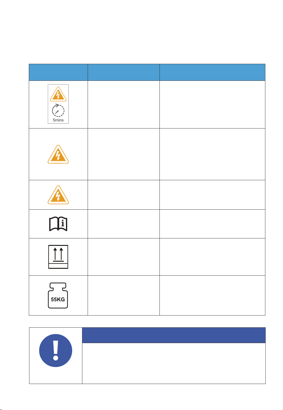
1.11 Label Description
Attention
The symbols on the box contain important information for safe
operation.
The nameplate on the side of the box contains important parameter
information related to the product.
Table 1-2 Labels and Description
Label Name Description
Discharge delay
Electrical shock
warning
There is still residual voltage after the
equipment is powered off. Please wait
at least 5 minutes until the equipment
is discharged.
The system generates high voltage
during operation.
The installation, commissioning, and
maintenance should only be
performed by qualified professionals
or trained personnel.
Warning
Be careful. Hazards may occur
during operation.
Read instruction
Please read the instruction
carefully before operating the
energy storage system.
This side up
It must be transported, handled and
stored in the correct orientation. The
arrow always faces upwards.
Weight
The inverter and battery packs are
quite heavy and need to be carried
by several people.
This Side Up
•
•
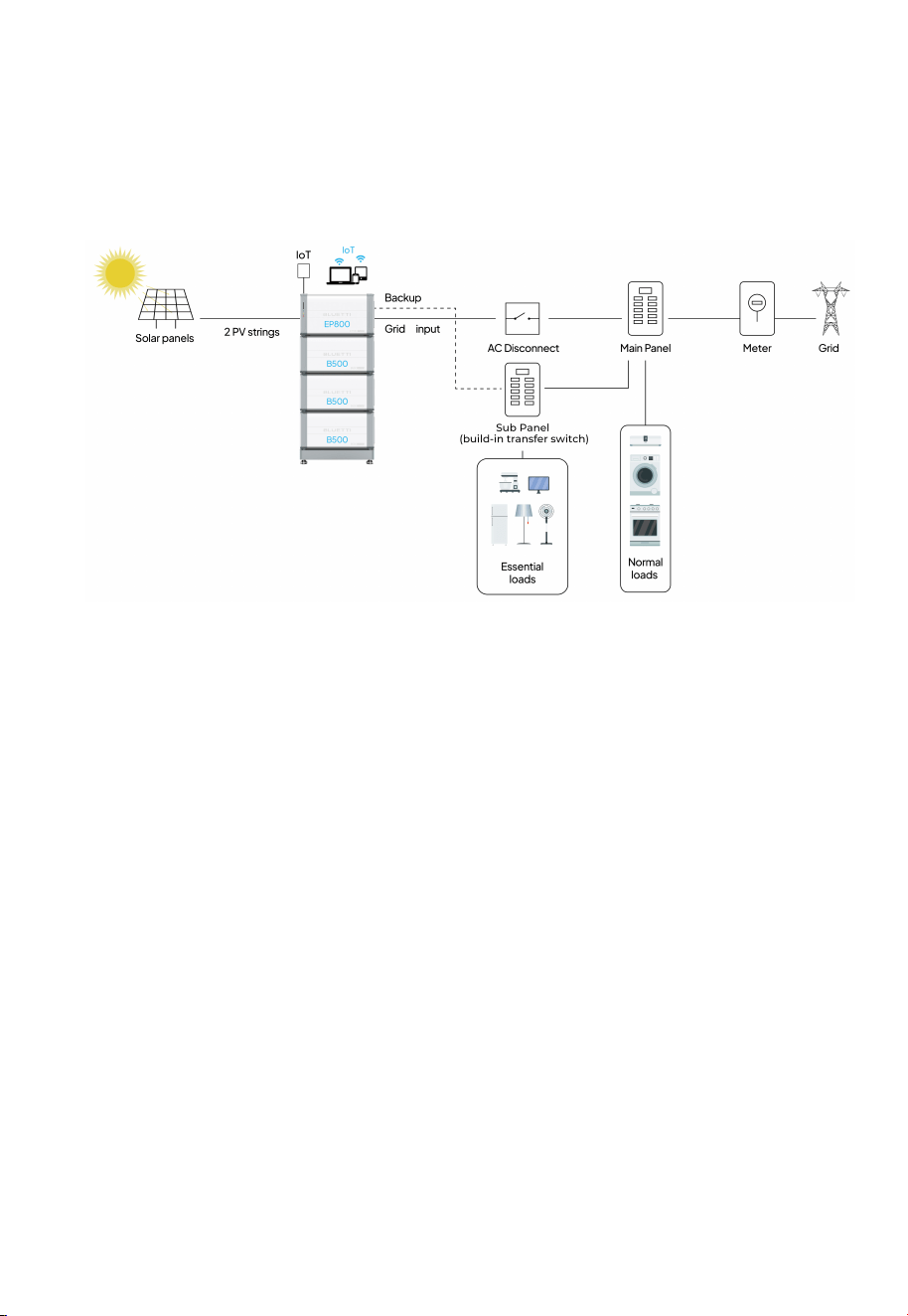
2. EP800 Home Energy Storage System
2.1 Introduction
EP800 is a Home energy storage power product that integrates PV application,
off-grid inverter, UPS function and LiFePO4 battery storage extension.
Note: This sketch only for reference , details according to the
needs of customer and must follow the NEC code.
JUST POWER ON18

2.2 Working mode
The EP800 offers three operating modes to accommodate various energy plans.
You can choose the one that best suits your home power supply configuration.
• Self-consumption
In this mode, the EP800 prioritizes the direct consumption of solar energy to meet
immediate household energy needs. Any surplus solar energy generated during the
day is intelligently stored in the battery for usage during peak hours or in the event
of a power outage. With such a strategy, the EP800 ensures an efficient and reliable
power supply, reducing reliance on the grid and promoting energy independence.
Table 2-1
Component Description
EP800
Inverter
Anenergy storage photovoltaic grid-con-
nected inverter to handle photovoltaic input,
grid-connected charging, and discharging.
Please refer to Chapter 3.
EP800 Home Energy Storage
Inverter for details.
Please refer to Chapter 4. B500
Battery for details.
Please refer to Chapter 5.
IoT Controller for details.
Please refer to EP800 Home
Energy Storage System BLUETTI
App User Manual for details.
Please purchase it
separately and contact
BLUETTI support before
making the purchase.
B500 Battery
LiFePO
4
battery pack, used to store
energy and power the EP800.
IoT Controller
A component to facilitate seamless near-end
communication (Bluetooth) or remote
communication (WiFi) with EP800 inverter.
BLUETTI App
An application to monitor and control the
EP800.
Rapid
Shutdown
A component to disconnect the DC input
from the solar system.
A component to disconnect the AC input
from the grid.
Sub Panel
A component that essential loads connect to.
Automatically switches to EP800 to power
essential loads during a power outage.
Manually switches to the grid for load power
in case of an EP800 malfunction.
Note
JUST POWER ON
19
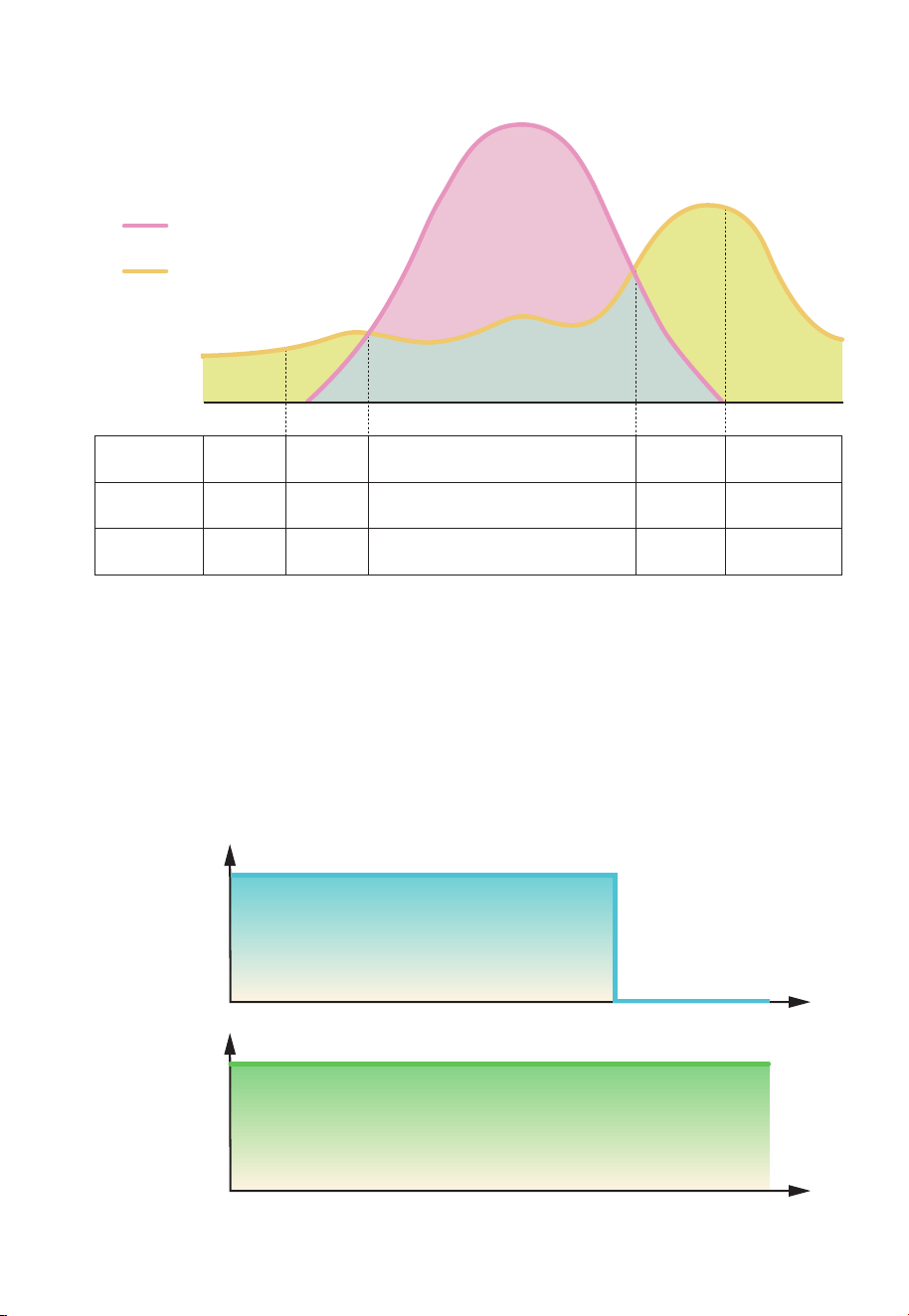
Input power
from grid
Time
Time
Backup side
output power
(W)
(W)
• Backup
In this mode, the EP800 acts as a reliable home backup power source that only
power from battery when the grid fails. It prioritizes charging its batteries from solar
energy over the grid, making it an eco-friendly and sustainable choice for your
home energy needs. With ample energy reserves, it provides a seamless power
supply, perfect for areas with unreliable grids.
Fig. 2-1
Fig. 2-2
EP800
Operation Status
Discharging
Midnight
Time
Morning Noon Afternoon Evening
DischargingDischarging Charging Discharging
Power Source
for Loads
EP800 EP800+Solar Solar EP800+Solar EP800
PV Generation
Used for
/ Loads Loads and Batteries Loads /
Household
runs on EP800
Household
runs on
EP800+Solar
Direct consumption
> Storage
Household
runs on solar
PV generation
Household consumption
Household
runs on
EP800+Solar
Household
runs on EP800
JUST POWER ON20
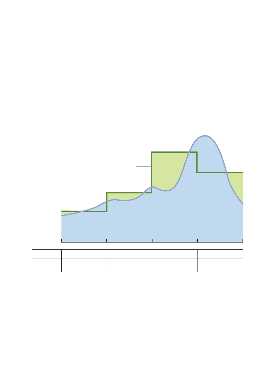
• Time of Use
In this mode, you can customize the charge and discharge periods as well as
charging power according to your specific requirements. During the charge period,
the EP800 will draw power from the grid, usually making use of off-peak tariff time
windows (TOU) when electricity rates are lower, to replenish its energy storage.
Moreover, you can set the battery State of Charge (SoC) limits to regulate the
amount of power that the EP800 draws from the grid, while reserving the remaining
capacity in the battery for solar energy supplement.
You can set this mode via the BLUETTI App. For details, please refer to EP800 Home
Energy Storage System BLUETTI App User Manual.
Fig. 2-3
Period
Power Source
for Loads
Charging
Grid
Discharging Discharging Discharging
EP800/EP800+PVEP800/EP800+PV EP800
Electricity Price
Home Consumption
0:00 6:00 12:00 18:00 24:00
JUST POWER ON
21

Fig. 2-4
JUST POWER ON22
• Custom Mode
In this mode, you can customize all of the above mode settings to your preference
on the BLUETTI App.
Note: Mode availability may vary by version.
EP800
Operation Status
Charging
2:00
Time
6:00 12:00 18:00 22:00
DischargingDischarging Discharging Discharging
Period Charging DischargingDischarging Standby Standby
PV Generation
Used for
/ Batteries Loads and Batteries Batteries /
Power Source
for Loads
Grid EP800+PV EP800 EP800+PV EP800
Household
runs on EP800
Household
runs on
EP800+Solar
Direct consumption
> Storage
Household
runs on solar
PV generation
Household consumption
Household
runs on
EP800+Solar
Household
runs on EP800
3. EP800 Home Energy Storage Inverter
Table 3-1
Left Right
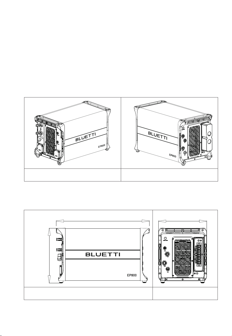
3.2.2 Dimensions
Table 3-2 (Unit: in/mm)
Front Right
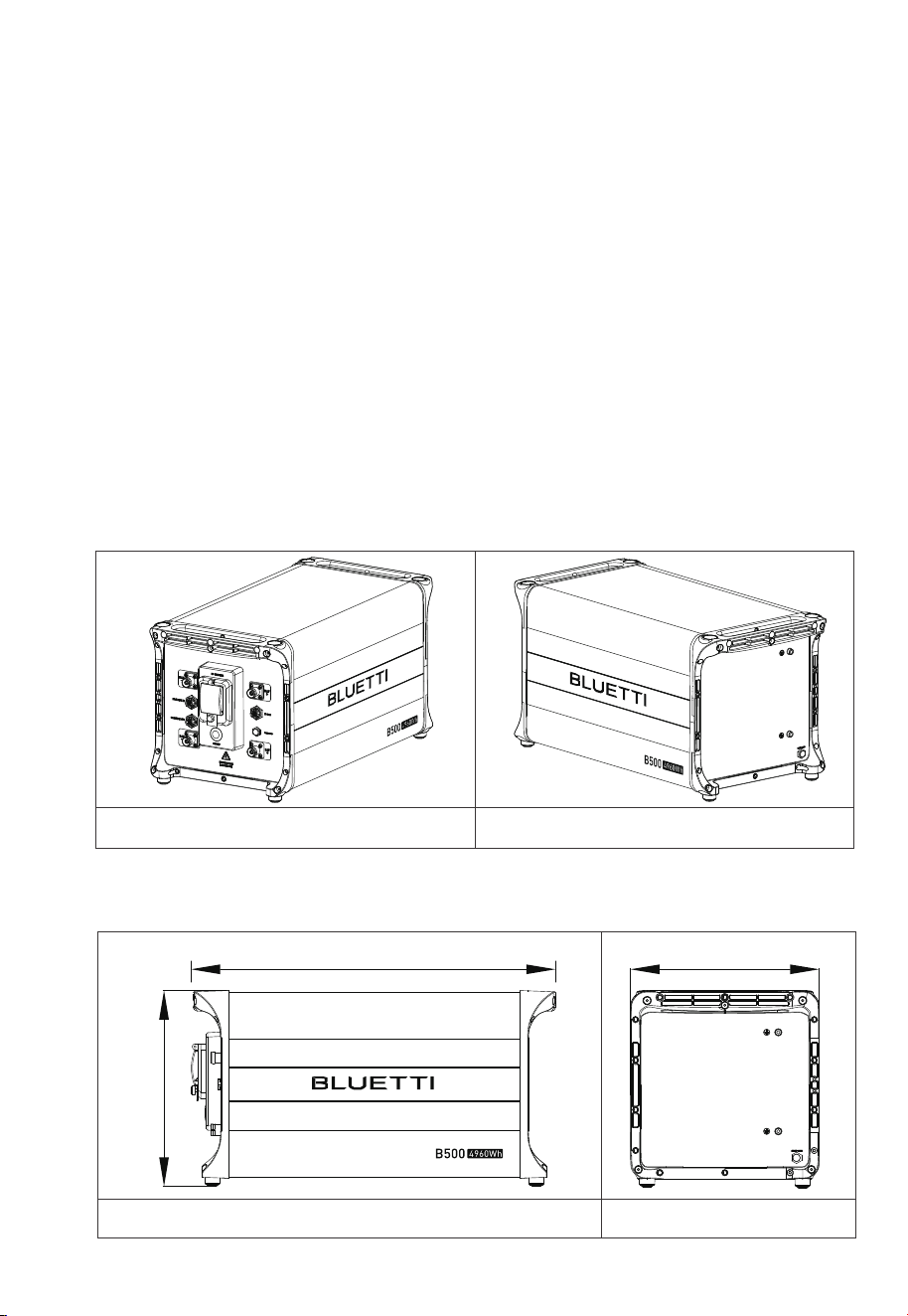
3.2 Inverter Overview
3.2.1 Appearance
14.567in(370mm)
25.039in(636mm)
12.795in(325mm)
JUST POWER ON
23
3.1 Introduction
EP800 inverter is an integrated split-phase photovoltaic energy storage inverter that
can handle photovoltaic (PV) input, grid-connected charging. It is an important part
of the home energy storage system.
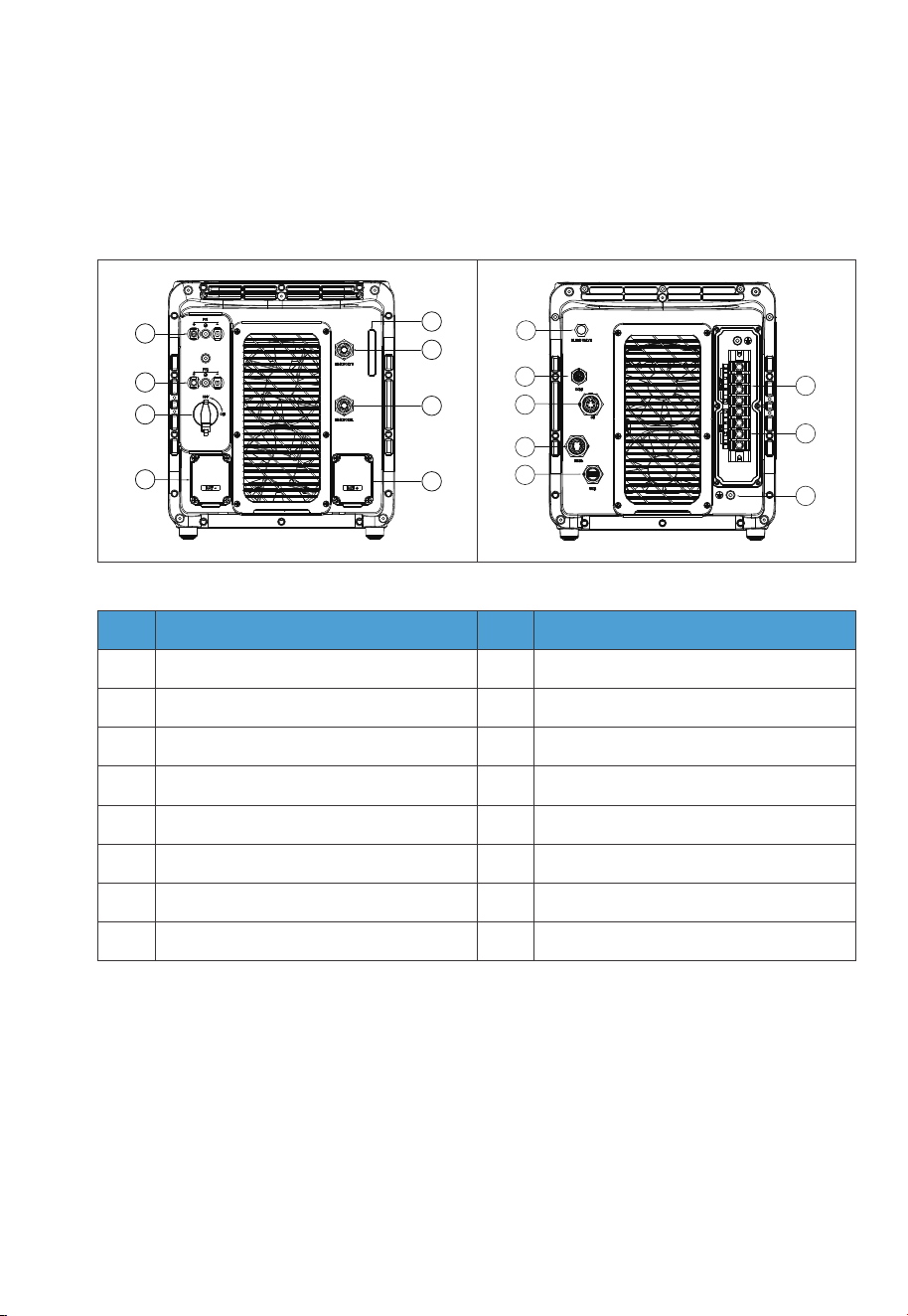
Table 3-3
Left
No.
1
2
3
4
5
6
7
8
PV1 Input
PV2 Input
DC Switch
BAT- Terminal
LED Indicator
LINK PORT1
LINK PORT2
BAT+ Terminal
BLEED VALVE
COM
CT
DRMs Port (Generator Input)
USB Port
BACKUP Terminal
GRID Terminal
GND Terminal (Grounding)
9
10
11
12
13
14
15
16
No.Name Name
Right
9
10
11
12
13
14
16
15
1
2
3
4
5
6
7
8
3.3 Interfaces
3.3.1 Interface Description
JUST POWER ON24
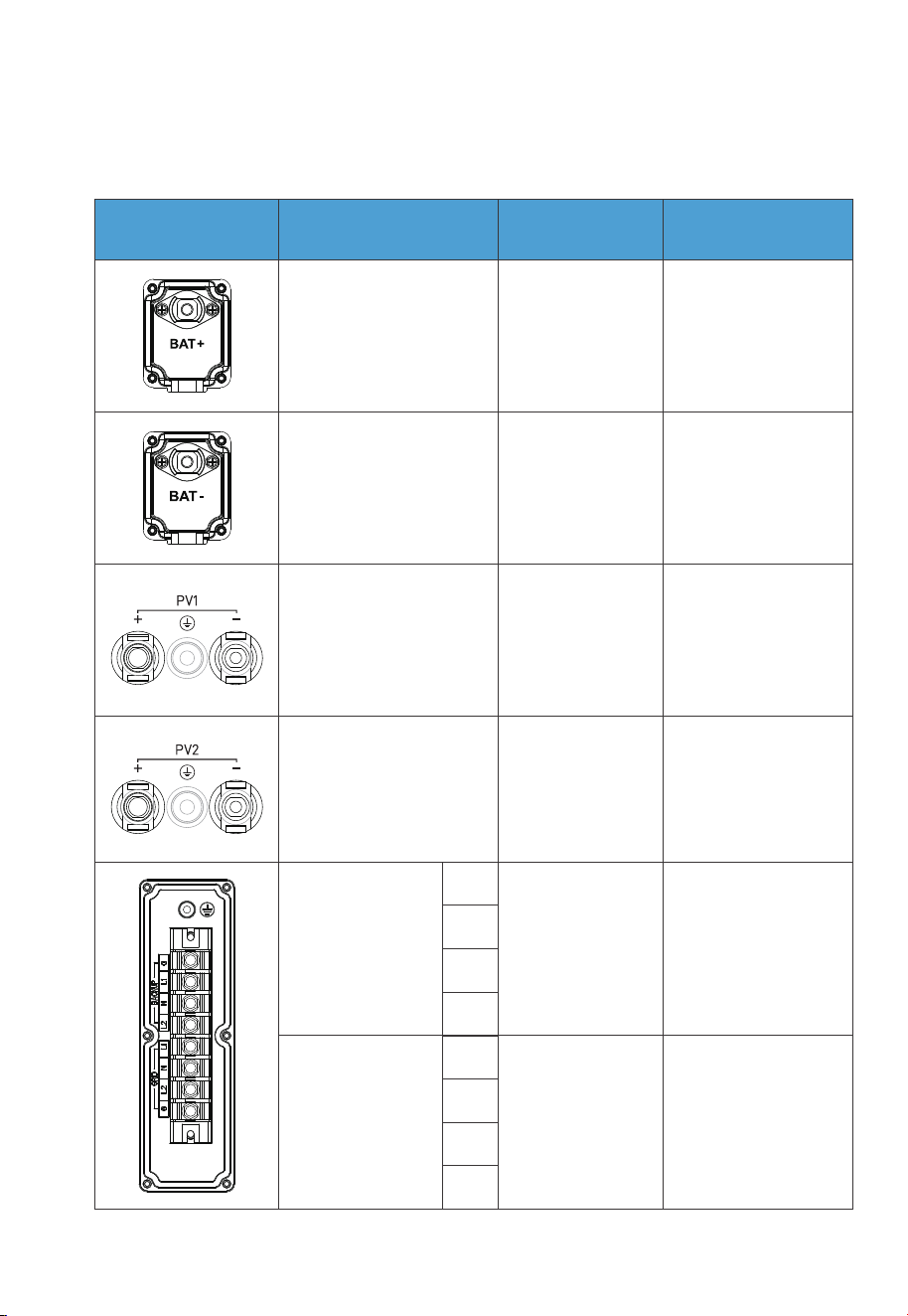
3.3.2 Wiring Interface Instructions
Table 3-4
Minimum wire size:
12AWG
Minimum wire size:
10AWG
Standard
accessories
BAT+: to the battery
BAT+ terminal
BAT-: to the
battery BAT- terminal
Standard
accessories
Outdoor multi-core
copper cable
Outdoor multi-core
copper cable
Minimum wire size:
6AWG
Minimum wire size:
6AWG
Outdoor multi-core
copper cable
Outdoor multi-core
copper cable
BACKUP
G
L1
N
L2
L1
N
L2
G
GRID
Terminal
Type of Cable
Required
Description
Cable specification
PV1+: to the positive
terminal of solar panel
PV1-: to the negative
terminal of solar panel
PV1 PE: PV1 grounding
PV2+: to the positive
terminal of solar panel
PV2-: to the negative
terminal of solar panel
PV2 PE: PV2 grounding
JUST POWER ON 25
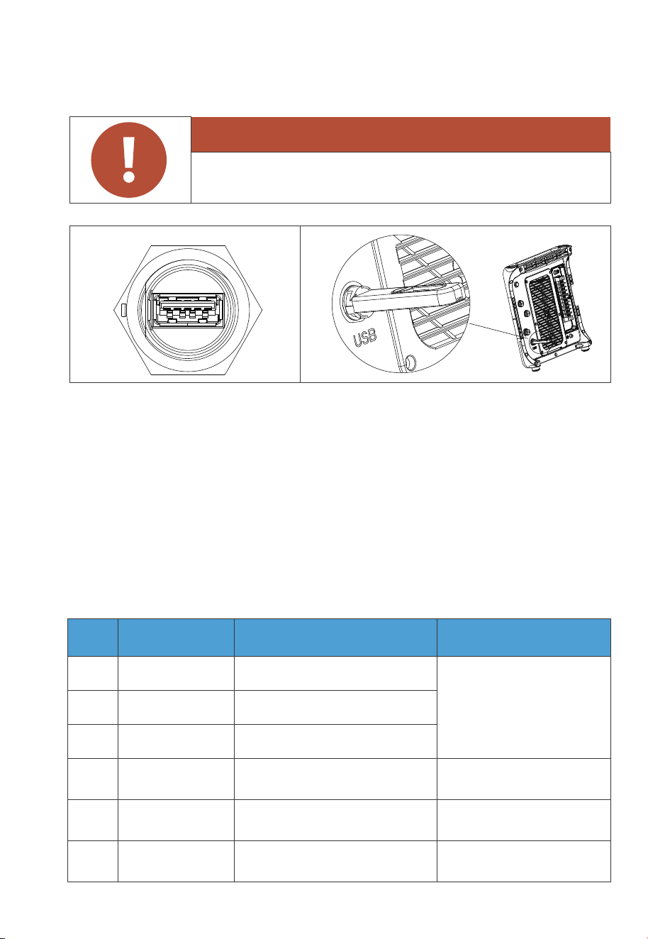
3.3.3 USB
3.3.4 DRMs Port
Fig. 3-1
The port is used for EP800 inverter firmware upgrade.
The USB drive should be formatted as FAT32 with no more than 32G in size.
The EP800 offers the flexibility to be upgraded for solar energy storage, allowing you
to harness more power form the sun. Additionally, it features a DRM interface
specifically designed to serve as a convenient ignition reserve port for generators,
ensuring a seamless integration of backup power solutions.
Table 3-5
PIN Category Definition Specifications
2
External DC input limit:
30VDC / 3A.
(For generator input)
Single-pole & double-throw
relay normally closed output
3
Single-pole & double-throw
relay normally open output
GEN NO
GEN NC
1
Single-pole & double-throw
relay common terminal
GEN COM
JUST POWER ON26
Warning
Only for USB drive access, not for USB charging.
6
B: RS485 differential signal -485-B3
5
A: RS485 differential signal +485-A3
4
Signal groundINS GND
Connect to meter A2
Connect to meter B2
/
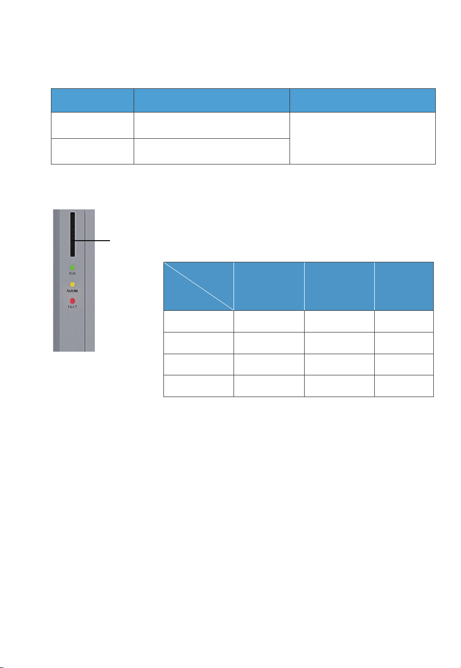
3.4 LED Indicators
3.5 Buzzer Alarm
When a fault occurs, the buzzer emits a series of 5 beeps. Each beep lasts for 2
seconds, with a 3-second interval between each beep.
Note: The buzzer alarm can be turned off in the BLUETTI App.
Fig. 3-2
3.3.5 LINK PORT 1 & LINK PORT 2
Table 3-6
Table 3-9
Interface Function Note
Refer to Fig. 6-8 for details.
Link Port 1
Link Port 2
Connect the IoT controller
Connect the battery pack
System
Status
Run ON OFF OFF
ON ON OFF
OFF OFF ON
OFF ON ON
Run +Alarm
Fault
Alarm and fault
Green Yellow Red
LED
Indicator
JUST POWER ON 27
3.6 Inverter Cables
Fault Code
B005.
B006.
B007.
B008.
B010.
B011.
B026.
B027.
B034.
Hardware BUS overvoltage
Hardware BUS2 overvoltage
Hardware Battery overvoltage
Hardware Inverter overcurrent
Hardware LLC1 current overcurrent input
Hardware LLC2 current overcurrent input
Hardware PV1 fault
Hardware PV2 fault
Hardware Overcurrent input
Please contact the BLUETTI support team.
Please contact the BLUETTI support team.
Please contact the BLUETTI support team.
TroubleshootingDescription
Picture Description Interface (connect to)
Red battery power cable (Positive)
Black battery power cable (Negative)
Generator communication cable
BAT+
BAT-
DRMs port
Turn off the inverter and wait 30
minutes to restart it. If the
symptom persists, please
contact the BLUETTI support.
Note: Please refer to Chapter 11. Troubleshooting for details.
Table 3-10 Fault Code
Table 3-11 Inverter Cables
JUST POWER ON28
12.795in(325mm)
13.307in(338mm)
25.039in(636mm)
Left Right
4. B500 Battery
4.1 Introduction
The B500 battery energy storage system is designed for residential and light
commercial use. Single B500 battery pack has a capacity of 4.96kWh. BLUETTI
EP800 supports 4 *B500 units for a whopping 19.84kWh.
The B500 comes with a reliable battery management system (BMS) with a
multi-stage architecture that provides real-time detection of the battery pack's
voltage, current and temperature, protecting the system from overvoltage, under-
voltage, overcurrent, overtemperature and undertemperature. At the same time,
the redundancy design provides unprecedented safety and stability for the B500
battery energy storage system.
4.2 Overview
4.2.1 Appearance
Table 4-1
4.2.2 Dimensions
Table 4-2 (Unit: in/mm)
Front Right
JUST POWER ON 29
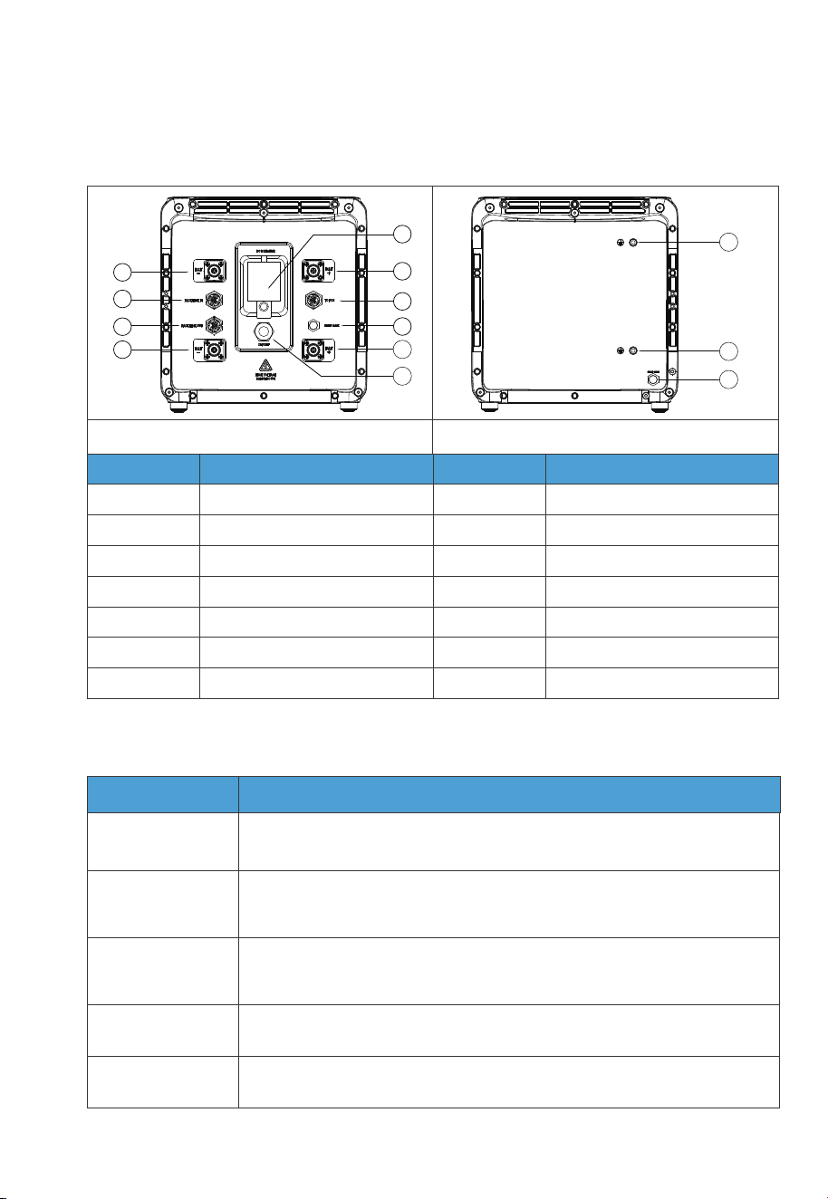
4.3.2 Wiring Interface Instructions
Interface
To Pcs
(Inverter signal port)
For communication between inverter and battery packs. Only the top
B500 needs to be connected to the LINK PORT 2 of the inverter.
Connect to the BAT+ terminal of another B500 or the inverter.
Connect to the BAT- terminal of another B500 or the inverter.
For communication between battery packs. Connect to the PACK LINK
OUT port of the upper battery when multiple B500s are stacked (except
for the top B500).
For communication between battery packs. Connect to the
PACK LINK IN port of the lower battery when multiple B500s are stacked
(except for the bottom B500).
PACK LINK IN
PACK LINK OUT
BAT+ terminal
BAT- terminal
Description
Table 4-4
1
2
3
4
5
6
7
8
9
10
11
12
13
Table 4-3
Left
No.
1
2
3
4
5
6
7
No.
8
9
10
11
12
13
BAT- terminal 1
Pack link-in
Pack link-out
BAT- terminal 2
Main switch
BAT+ terminal 1
To Pcs(Inverter signal port)
Bleed valve 1
BAT+ terminal 2
Power button
Grounding port 1
Grounding port 2
Bleed valve 2
Name Name
Right
4.3 Interfaces
4.3.1 Interface Description
JUST POWER ON30

4.4 LED Indicators
Light
OFF B500 is not started. Can operate the circuit breaker.
Can not operate the circuit breaker.
Can not operate the circuit breaker.
B500 is running.
B500 is shutting down.
B500 is not running.
ON
Flash at 0.5Hz
Flash at 1Hz
Description Note
If all indicators are flashing, the battery
module is temporarily unavailable and is
restoring, please wait patiently.
If it lasts for more than 1 hour, please
contact an authorized dealer or our
company.
If a single indicator flashes, the B500 is in
a fault condition. Please contact an
authorized dealer or our company.
Table 4-5
4.5 Battery Cables
Picture Description Interface (connect to)
Communication cable
Red battery expansion cable (Positive)
Black battery expansion cable (Negative)
Grounding cable
BAT+ terminal 2
BAT- terminal 2
Grounding port
Table 4-6 Battery Cables
LINK PORT 2 of
the inverter
JUST POWER ON 31
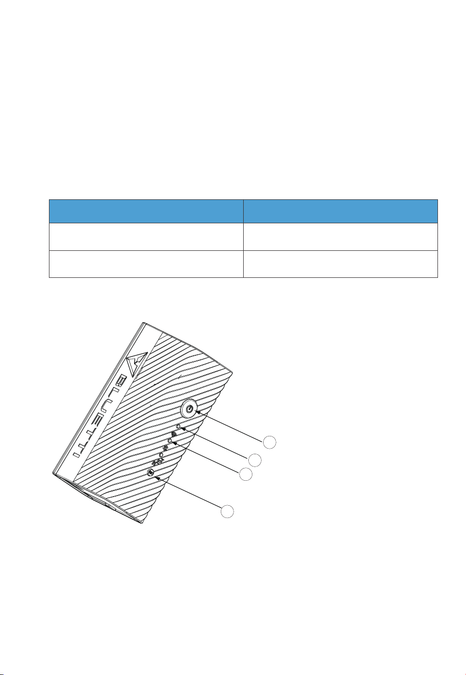
5. IoT Controller
5.1 Communication Principle
The IoT controller supports WiFi and Bluetooth dual-mode communication,
allowing connectivity between the EP800 and BLUETTI App. Everything about the
system, including power generation and consumption, alarms, and operating
status, can be uploaded to the BLUETTI server via the WiFi network. By registering
the EP800 with your BLUETTI App, you’re able to monitor and control this unparal-
leled power plant anytime and anywhere.
Table 5-1
Communication
WiFi
Bluetooth
Standard
Standard
Note
5.2 Overview
1.Menu Button.
To factory reset the controller,
press and hold this button for
about 5s till all LED indicators flash.
2. WiFi Indicator.
Flash till the controller
connected to WiFi.
3. Bluetooth Indicator.
Flash till the controller
connected to Bluetooth.
4.Reboot Button.
Press to reboot the controller.
1
2
3
4
JUST POWER ON32

5.3 Safety Instructions
•
The IoT controller is ONLY applicable to BLUETTI products only.
• Do not keep the controller near heat sources or in high temperatures.
• Do not store the controller with flammable liquids, gases, or explosive materials.
• The inspection, testing, and maintenance should be performed by qualified
personnel.
Warning
• Do not block or cover the openings of the controller.
Keep it out of the reach of children.
• Use dry powder fire extinguisher in case of fire.
5.4 Connection and Operations
Step1: Plug the IoT cable into EP800 Link Port 1.
Step2: Turn on EP800, and the IoT controller starts up automatically.
Step3: When an upgrade is needed, please follow the instructions provided in the
EP800 Home Energy Storage System BLUETTI App User Manual.
To register and log in, simply follow the steps below:
• Scan the QR code below to download the BLUETTI App, or search for “BLUETTI” in
the App Store/Google Play.
JUST POWER ON 33
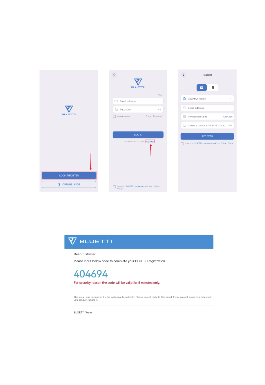
• Check your email for verification code from BLUETTI server, and fill in the code to
activate your BLUETTI account.
• The BLUETTI app connects to EP800 via Bluetooth or WiFi. Tap “LOGIN/REGISTER”
and “Sign up” to register your BLUETTI account. Fill in the necessary information to
continue.
JUST POWER ON34
JUST POWER ON 35
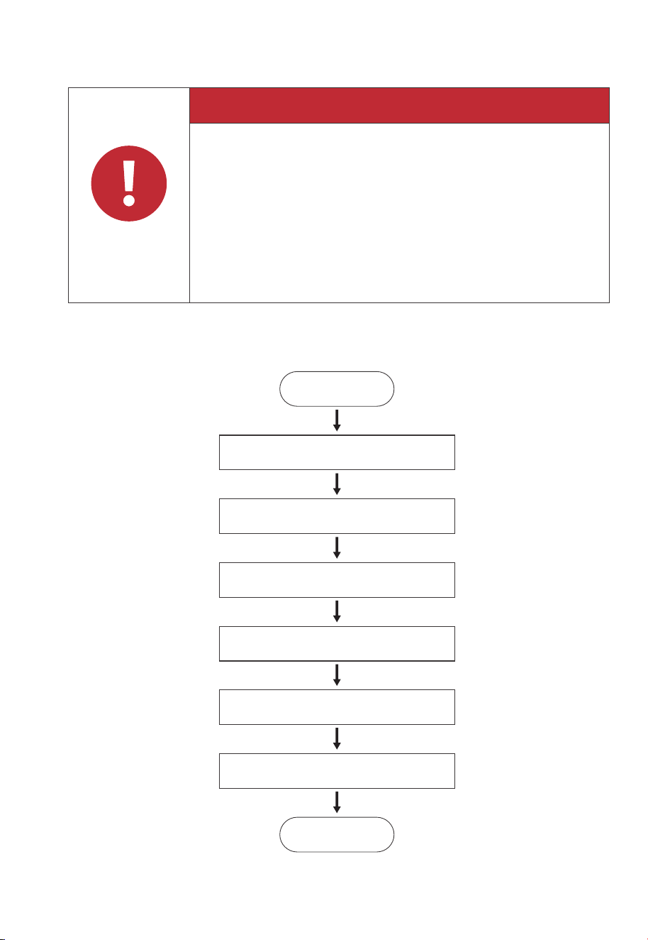
6. System Installation
6.1 Installation Procedure
Danger
When the EP800 is not activated, the grid side and off-grid side are
directly connected. Therefore, it is important not to touch any
exposed terminals to ensure safety.
When the grid side is powered on, the off-grid side will also be
energized with AC output. Please strictly adhere to safety operating
procedures to avoid electric shock.
Before installation, disconnect all circuit breakers for the battery pack,
solar system, and the main switch of the grid to ensure safe operations.
Required minimum space for the EP800 system installation is 23.15 m
3
.
Start
Preparation
Stacking the batteries
Installing the inverter
Installing the IoT controller
Electrical Connection
System Check
End
•
•
•
•
•
•
JUST POWER ON36
1 1
2 2
2
2
3
4
EP800 inverter
Bracket #1
Bracket #2
M5 hex nut
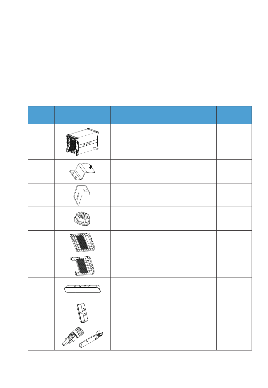
No. DescriptionPicture Qty.
1
1
5
6
Plastic cover (PV)
Plastic cover (AC, with label)
1
2
2
7
8
9
Cord organizer
AC cable protection case
Plastic housing (PV+ Input)
Metal core (PV+ Input)
6.2 Preparation
6.2.1 Check Packing List
Upon receiving the package, we kindly ask you to carefully inspect and verify the presence
of all components and accessories included.
EP800 Inverter Packing List
Table 6-1
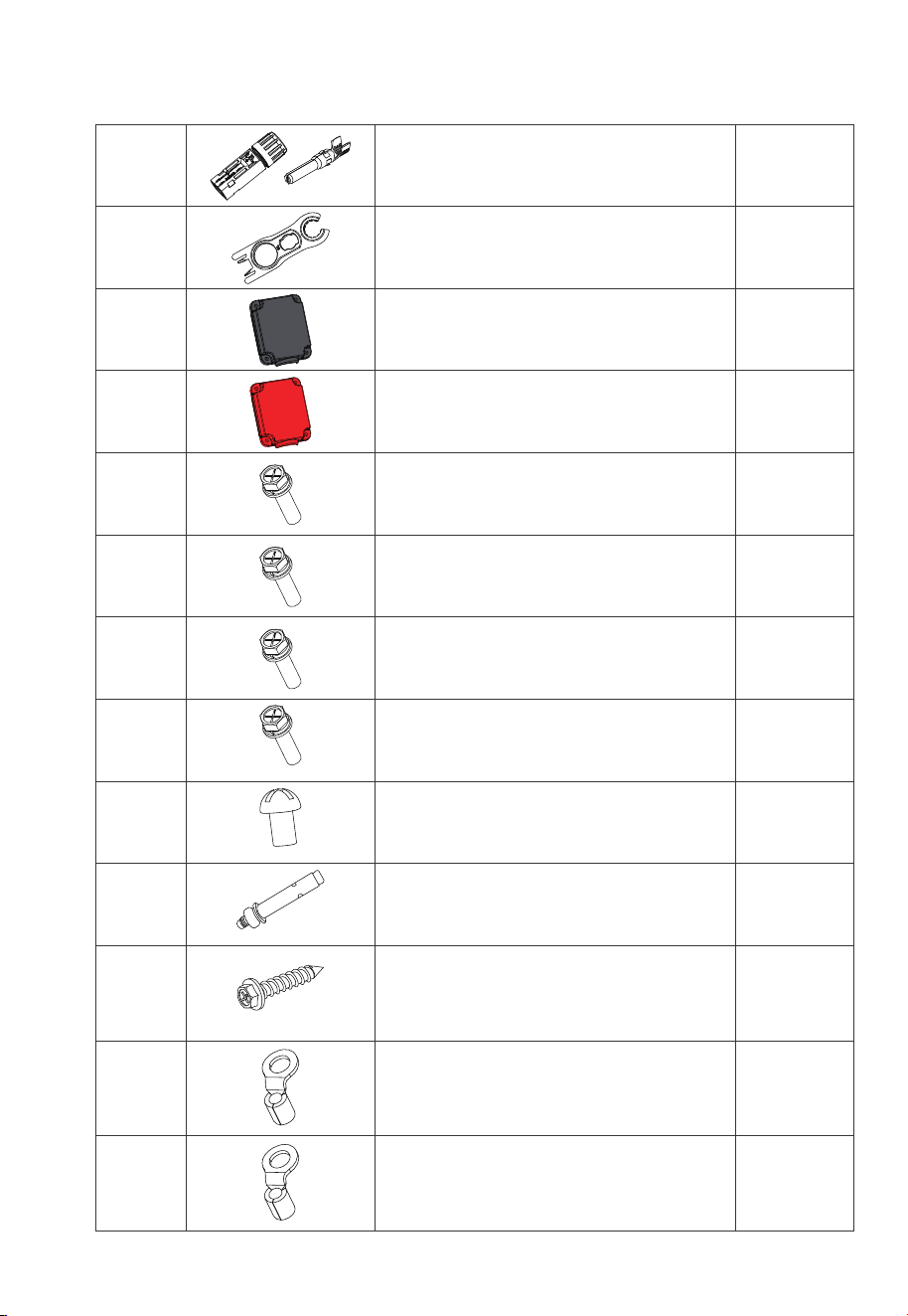
JUST POWER ON 37
210
Plastic housing (PV- Input)
Metal core (PV- Input)
11
12 1
2
Black protection cover (BAT- Input)
(Pre-installed on EP800 inverter)
MC4 wrench
6
2
2
2
10
16
17
18
19
M6*12 screw
(For bracket, pre-installed on EP800 inverter)
M5*10 screw
(4 for fixing device to the bracket,
2 for PV grounding)
M4*10 screw
(For exterior trim)
M8*60 expansion bolt
13 1
1414
Red protection cover (BAT+ Input)
(Pre-installed on EP800 inverter)
M4*12 screw (8 for BAT+/- protection cover,
6 for AC cable protection case,
pre-installed on EP800 inverter)
215
M8*12 screw
(For battery power cable)
7
3
20
21
RNB8-6S OT terminal (AC)
RNB3.5-5S OT terminal (PV Grounding)
22
Self-tapping screw, ST8×40
JUST POWER ON38
23
24
1
1
1
1
2
25
26
Black battery power cable (Negative)
Red battery power cable (Positive)
IoT Controller
Mounting bracket
(IoT controller)
Expansion wall plug
27
2
28
M3 tapping screw (KA3*25)
1
29
DRMs communication cable (4m / 13ft)
JUST POWER ON 39
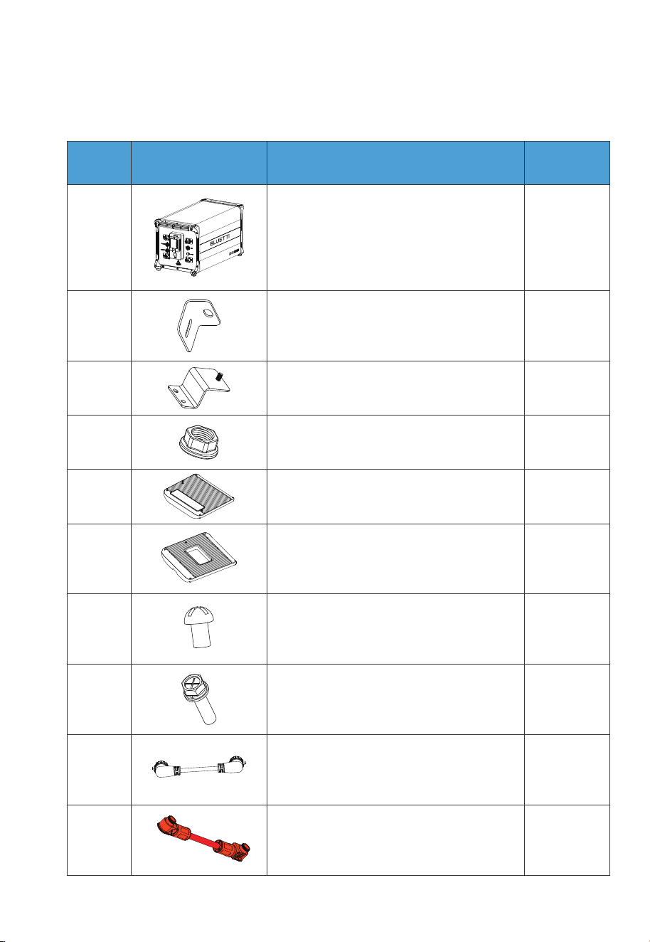
B500 Battery Packing List
1
2 2
1
23
B500 Battery Module
Bracket #1
Bracket #2
No. DescriptionPicture Qty.
24 M5 hex nut
15
Left cover
1
10
4
6
7
8
Right cover
M4*8 screw (for fastening covers)
M5*10 screw (for brackets)
1
1
9
10
Communication cable
Red battery expansion cable (Positive)
Table 6-2
JUST POWER ON40
6.2.2 Base Packing List
1
1
Base
No. DescriptionPicture Quantity
12
11
1Grounding cable
1Black battery expansion cable (Negative)
2
2
13
14
M8*60 expansion bolt (for brackets)
Self-tapping screw, ST8×40
2
1
15
16
M6*12 screw (Grounding cable)
Spare screw kit
Table 6-3 Base Packing List
JUST POWER ON 41
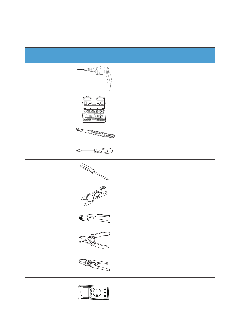
6.2.3 Required Tools
1
2
3
4
5
6
7
8
9
10
Electric drill
(0.197/0.315/0.394(in)
5/8/10(mm))
Socket wrench set
Torque wrench
Flat screwdriver
Cross screwdriver
(0.157in/4mm)
MC4 spanner
Cable cutter
Cable stripper
Cable Crimper
Multimeter
(DC voltage ≥
1000VDC)
No. DescriptionPicture
Table 6-4 Required Tools
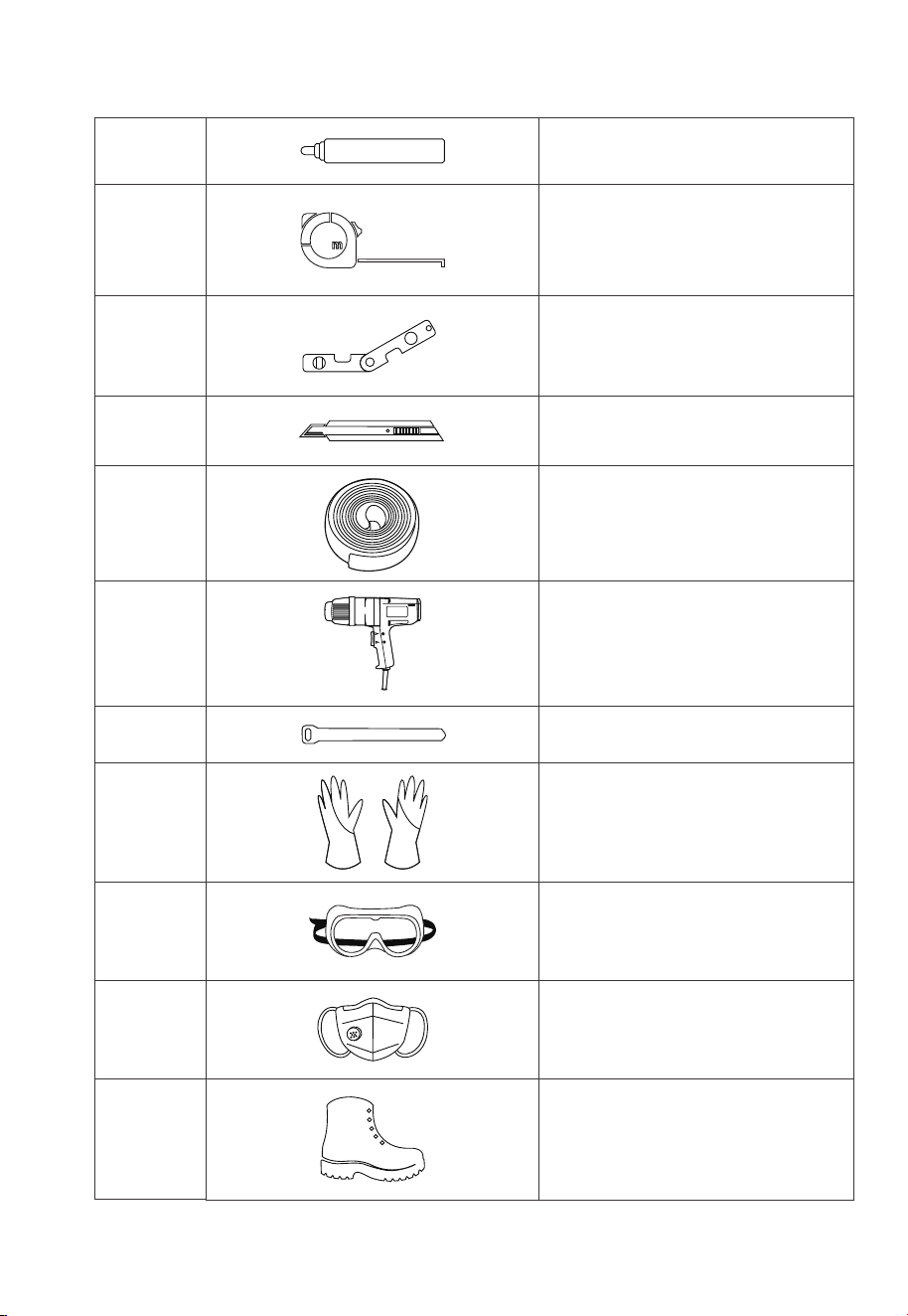
JUST POWER ON42
12
11
13
14
15
16
17
18
19
20
21
Measuring tape
Marker
Level ruler
Box cutter
Heat shrink tubing
Heat gun
Cable tie
Anti-static gloves
Protective goggle
Mask
Safety-toe shoes

JUST POWER ON 43
23
22
Vacuum cleaner
Allen driver
6.3 Installation Requirements
6.3.1 Environment Requirements
•
Install the EP800 in a well-ventilated and spacious area to ensure good heat
dissipation.
• The EP800 has an IP65 rating and can be installed indoors and outdoors. Please
note that if you place the system outside the house, use a cabinet to protect it from
direct sunlight, as this may cause a degradation in system performance.
• The enclosure and heat sink are very hot while the inverter is working, therefore do
NOT install the inverter in places where you might touch inadvertently.
• Keep the EP800 away from flammable liquids, gases, or explosive materials.
• Keep away from children and pets.
• Do not install the EP800 outdoors in salt-affected areas, as the accumulation of salt
may corrode the system. Salt-affected areas are those within 500 meters from the
coast or susceptible to sea breezes. Salt accumulation is influenced by seawater,
sea breeze, precipitation, air humidity, topography and forest cover of adjacent sea
areas.
• Do not install the system in low-lying areas where water tends to accumulate.
Otherwise, water may leak into the equipment and result in system failure.
• Ambient temperature range: -4°F-104°F / -20°C-+40°C
• Relative humidity: 5%~95% (non-condensing)
• Maximum height: 6561ft / 2000m.
JUST POWER ON44
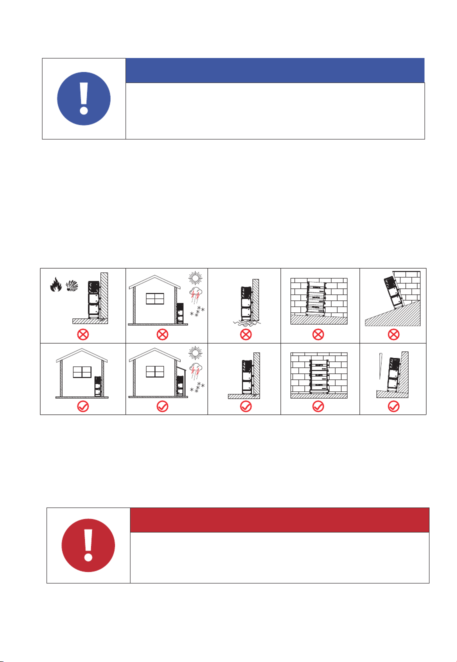
6.3.2 Location Requirements
•
The EP800 should be installed ona firm, flat, level base.
• Do not install the system on flammable materials.
• Consider the weight and placement of components to ensure adequate structural
support.
Attention
Danger
If the battery pack is dropped, violently impacted or tilted during
installation, it may result in internal damage. So do not use such battery
packs to avoid safety risks such as battery leakage and electric shock.
Fig. 6-2
Water
Fire or
Flammable
Material
Max. 5
o
6.3.3 Space Requirement
Danger
Make sure to check for any cables or pipes before drilling into the wall.
JUST POWER ON 45
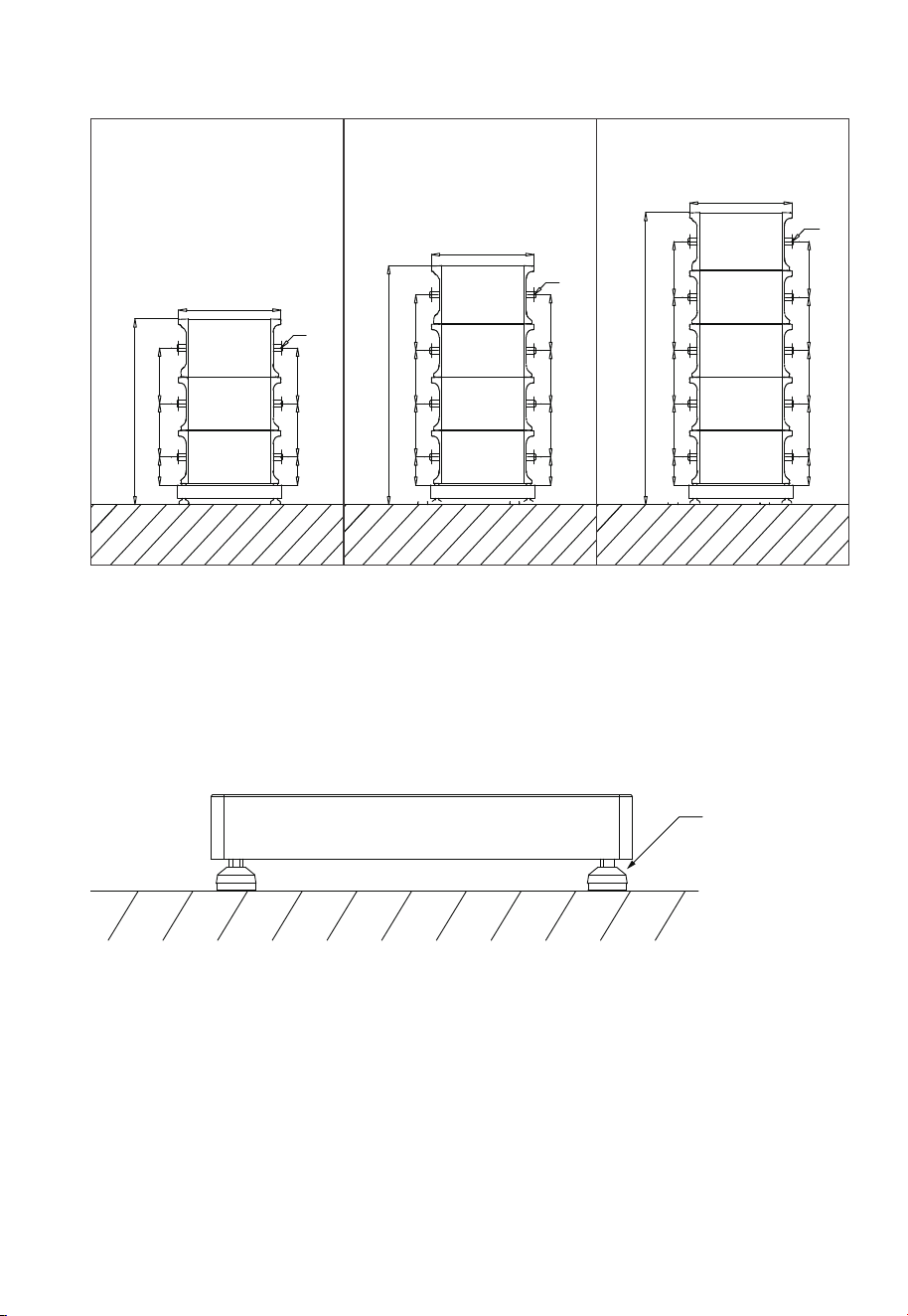
6.4 Stacking the Units
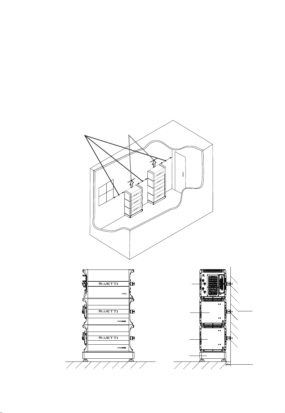
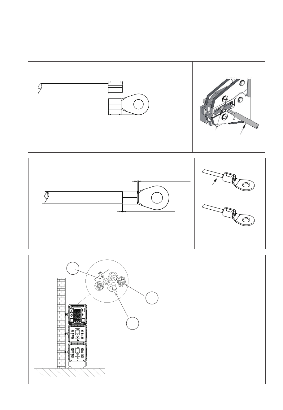
Step 1: Place the base on the ground and adjust the height of leveling feet so that
the base stands stably on the ground. Don’t forget to tighten the nuts to secure the
leveling feet.
Step 2: Mark the drilling positions with tape and marker. Drill holes with the M10
electric drill and insert M8 expansion bolts(Self-tapping screws for wooden walls).
Note: If you are working with a wooden wall, simply mark the positions and use M8
self-tapping screws to secure the unit directly onto the wall.
Step 3: Move the B500 battery pack to the base. Two people are required to transport
the B500. Align the bumps on the battery with the notches on the base to secure
the battery in place.
Fig. 6-3 (Unit: in)
Ground
The height of 4
leveling feet can
be adjusted.
Fig. 6-4
( 3 layers) ( 4 layers) ( 5 layers)
6.751 in
6.751 in
12.795 in
12.795 in 12.795 in
13.385 in
13.385 in
6.751 in 12.795 in 12.795 in 13.385 in
6.751 in 12.795 in 12.795 in 12.795 in 13.385 in
6.751 in 12.795 in 12.795 in 12.795 in 13.385 in
6.751 in
12.795 in 13.385 in
44.606 in
57.402 in
70.157 in
Ø0.315 in
Ø0.315 in
Ø0.315 in
24.724 in
24.724 in
24.724 in
JUST POWER ON46
Step 4: Fix 2 brackets #1 to two sides of B500 with 4 M5*10 screws. Put the bracket #2
through the compression rivet screw of bracket #1 and M8 expansion bolts. Secure
the connection with M8 and M5 nuts.
Step 5: Repeat Step3 and 4 to secure all battery packs.
Step 6: Follow the same steps to install the EP800 inverter on top.
Fig. 6-5
Ground
Wall
B500
Base
B500
EP800
55mm
2.15 in
40in
Door
Window
1 feet
Note: A set of EP800 energy storage system installation space needs to meet the
minimum 23.15m
3
.

JUST POWER ON 47
6.5 Install the IoT Controller
Danger
Make sure to check for any cables or pipes before drilling into the
wall.
To ensure a strong and uninterrupted wireless signal, it is recommended to install
the IoT controller in an open space, away from obstructions, and minimize the
distance between your home WiFi router and the IoT controller.
Avoid installing the IoT controller near steel-reinforced concrete or metal walls, as
these materials can interfere with WiFi and Bluetooth signals.
Step 1: Drill 2 pilot holes in the wall. Please refer to the drill position and hole size
shown in Fig. 6-6-1 and Figure 6-6-2. The depth of hole is 0.94in(24mm).
Step 2: Hammer the expansion wall plug in until it’s flush with the wall. See Fig. 6-6-3.
Step 3: Fix the mounting bracket onto the wall and use the cross screwdriver to
fasten 2 self-tapping screws into the wall plugs. See Fig. 6-6-4.
Step 4: Align the controller’s buckle over the U-slot and push the controller down-
wards until it snaps in place. See Fig. 6-6-5 and Fig. 6-6-6.
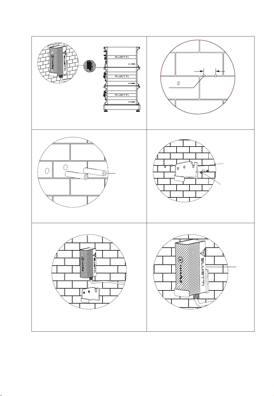
JUST POWER ON48
Fig. 6-6
Fig. 6-6-1 Fig. 6-6-2
Fig. 6-6-3 Fig. 6-6-4
Expansion
Wall Plug
Bracket
Self-tapping
Screw
0.94in (24mm)
2- 5.0
Fig. 6-6-5 Fig. 6-6-6
IOT
Controller
JUST POWER ON 49
6.6.2 Connection Procedure
6.6 Electrical Connection
6.6.1 Cables
Start End
Grounding Protection (PE)
Battery Power Cables
Communication Cables
PV Cables
GRID and BACKUP Cables
Table 6-5 Cables
Red battery power cable (Positive)
Black battery power cable (Negative)
Communication cable
Red battery expansion cable (Positive)
Black battery expansion cable (Negative)
Grounding cable
CablePicture
Fig. 6-7
JUST POWER ON50
Fig. 6-8
JUST POWER ON 51
6.6.3 Grounding Protection (PE)
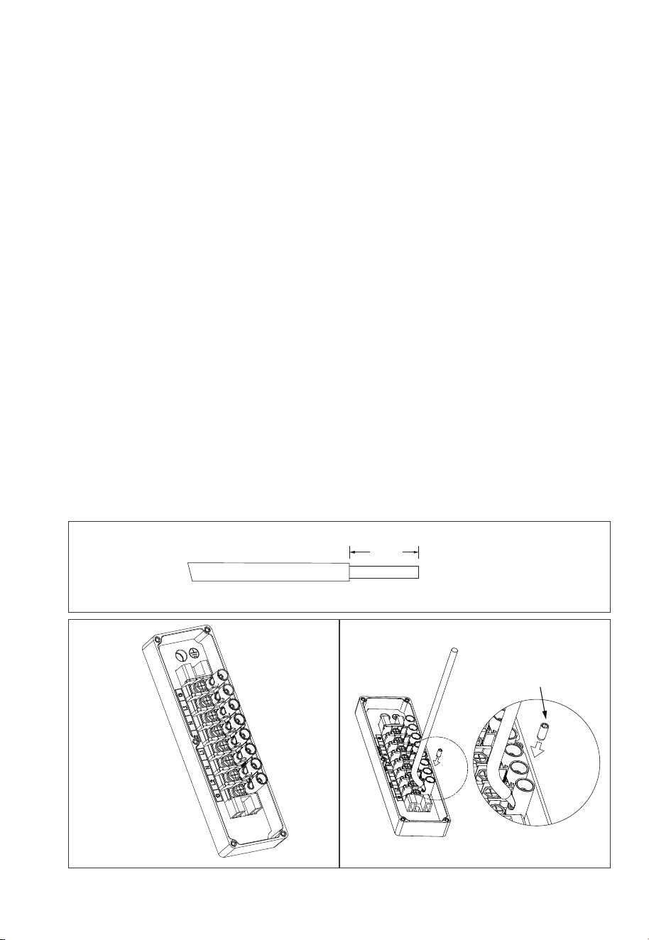
Step 1: It is recommended to use a 12AWG outdoor power cable and RNB3.5-5S OT
terminals. Strip the insulation layer of the ground cable with a cable stripper to a
proper length. See Fig. 6-9-1.
Step 2: Insert the exposed core wires into the OT terminal and crimp them with a
crimper, as shown in Fig. 6-9-2.
Step 3: Fix the OT terminal with M5 screws at the position shown in Fig. 6-9-3.
Recommended torque: 3N m (27 to 32 in-lbs).
Note: L3 is the length between the insulation of the cable and the crimped part. L4
is the length between the crimped part and core wires protruding from the
crimped part.
Danger
The positive and negative terminals of the PV (photovoltaic) system
inverter should not be grounded, as it may lead to inverter failure.
However, it is important to ground all non-current carrying metal parts,
including brackets, distribution boxes, inverter enclosures, battery pack
enclosures, and other relevant components.
B500
B500
6000W
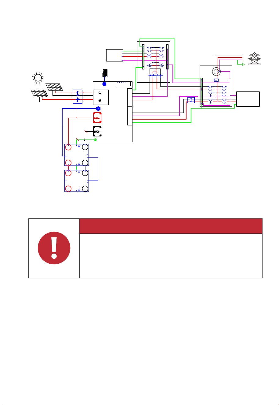
3000W
Solar panels
Solar panels
DRMs
2
1
3 4
2
1
3 4
meter
L1 L2
L1
L2
N
L1
L2
F1
F6
F2
F3
F4
F5
F7
F8
F9
L2
L1
L1
L2
BAT-
BAT-
BAT+
BAT+
BAT+
BAT+
BAT-
BAT-
TO PCS
PACK LINK IN
PACK LINK OUT
TO PCS
PACK LINK IN
PACK LINK OUT
1 2 3 4 5 6
L1
L2
N
GND
N
L2
L1
G
N
L2
L1
G
G
L2
L1
N
Standard
cable
Standard
cable
Earth
+
-
+
-
LINK PORT2
LINK PORT1
PV1
PV2
GRID
BACKUP
EP800
IOT BOX
G-N Link
G-Bar
N-Bar
1
2
3
4
Transfer
Switch
G-Bar
N-Bar
Essential
Load
Non-essential
Load
Main Panel
Sub Panel
QF1
QF2
L1
L2
N
12AWG
10AWG
10AWG
12AWG
Standard cable
Standard cable
JUST POWER ON52
L2 is L1+0.12in / 3mm longer than L1
6-9-1
L2=L1+0.12in / 3mm
L1
6-9-2 6-9-3
1
2
3
1 . M5×10 screws
2. OT terminal
3. PV grounding pole
L3≥0.08in / 2mm
L4≥0.04in / 1mm
Visible wire
Qualified
Wire even or bulge
up to 0.04in / 1mm
Figure 6-9-3 Grounding Connection
Terminal block
Wire
The cavity formed after crimping the conductor crimp strip shall wrap the core
wires completely. The core wires shall contact the terminal closely.
JUST POWER ON 53
1
2
4
3
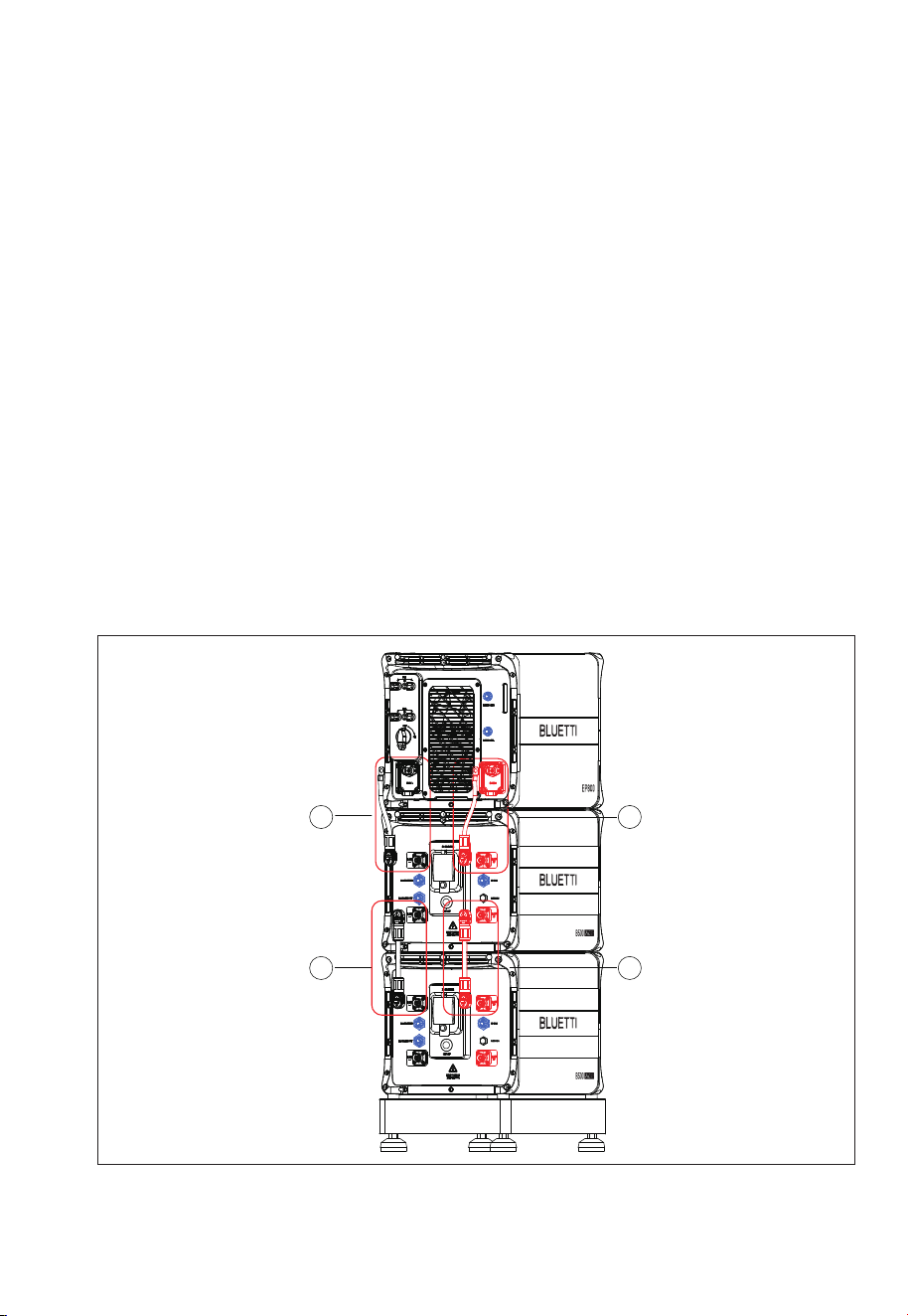
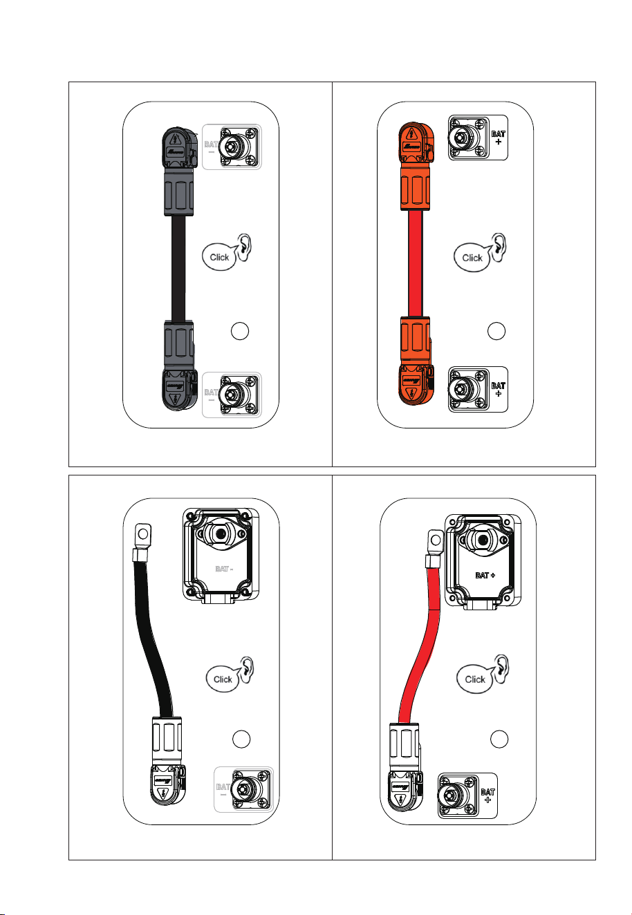
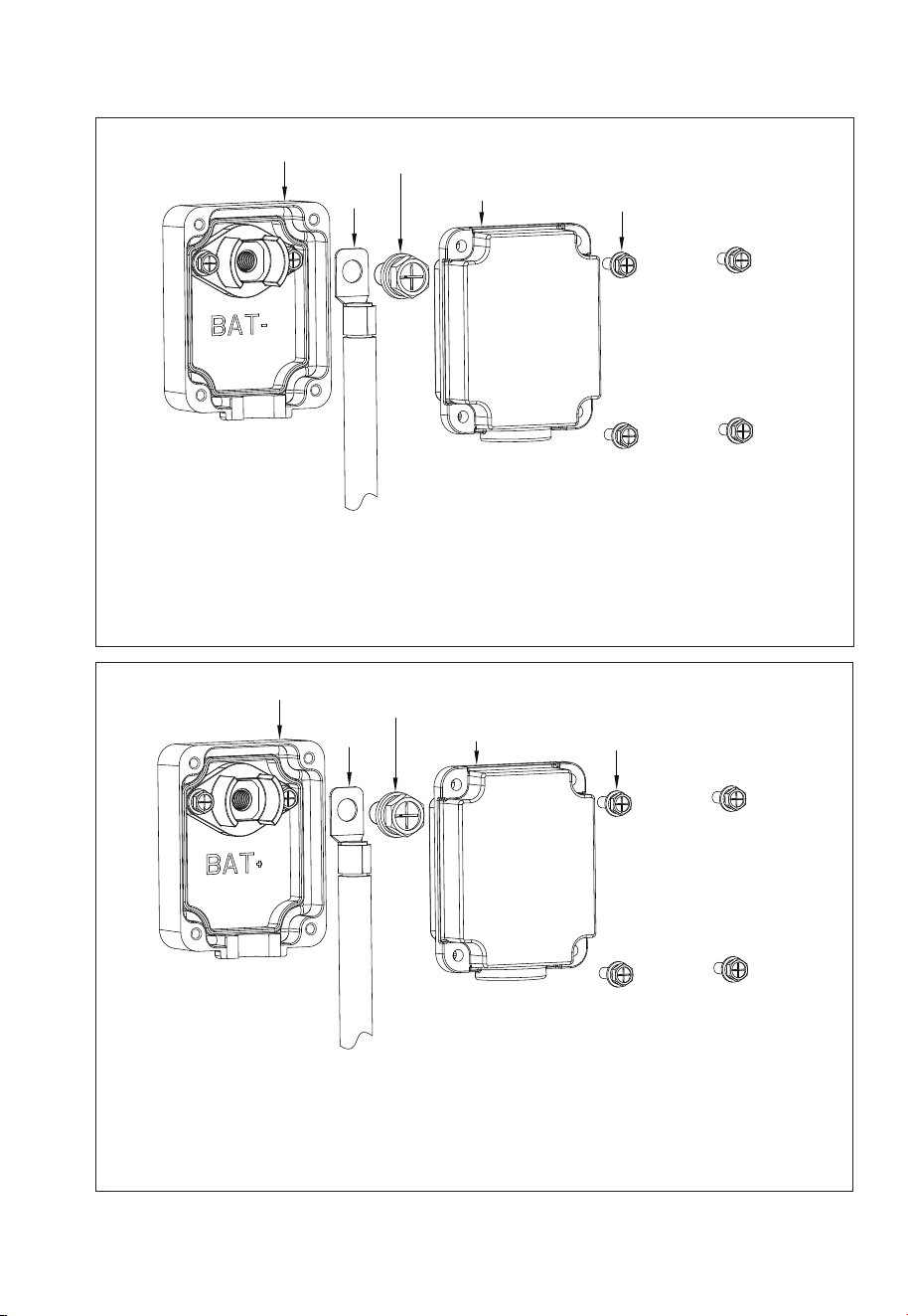
6.6.4 Battery Power Cable
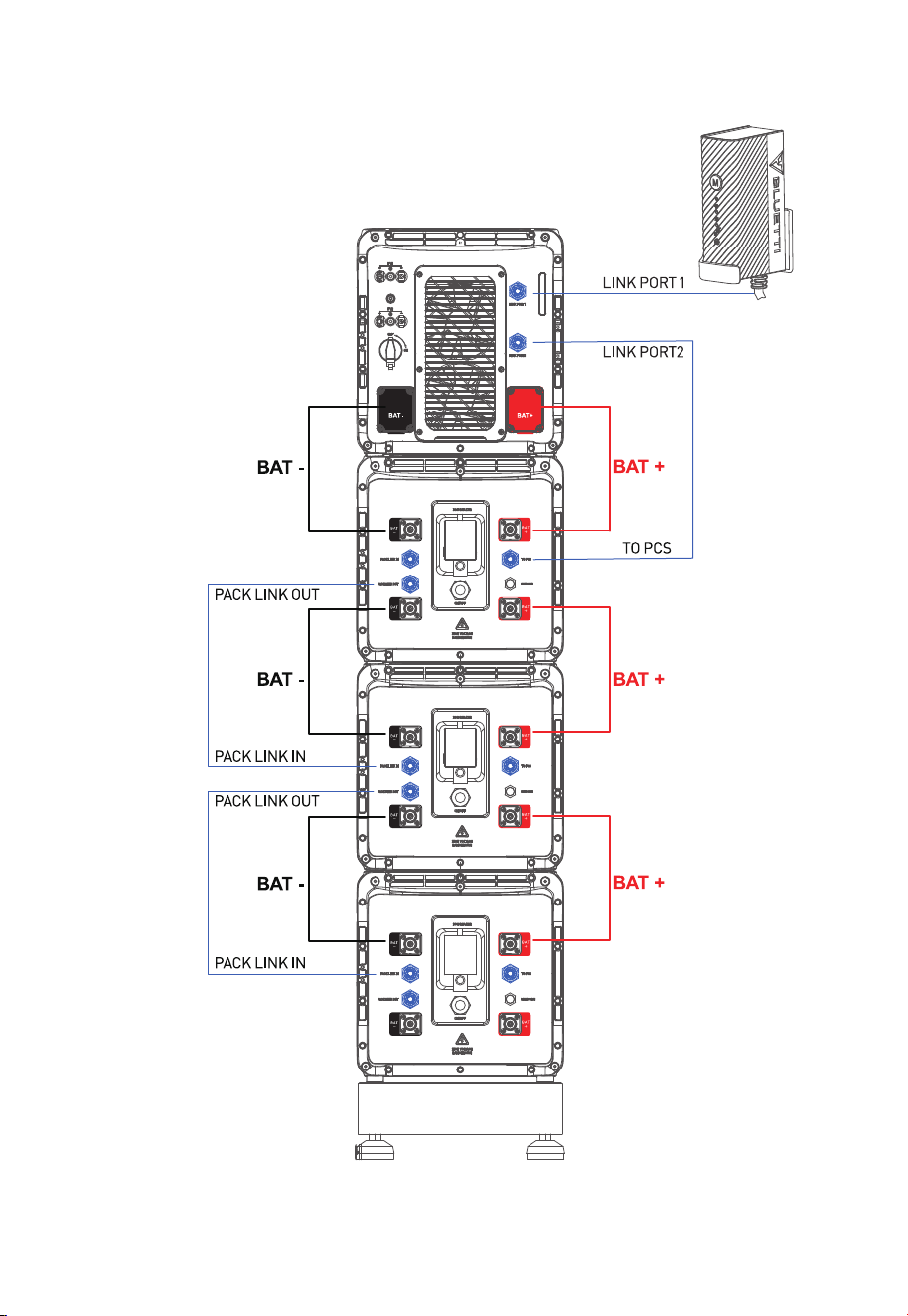
Step 1:Connect two B500 battery packs via the battery expansion cables - black
cable for negative terminals, red for positive terminals. See “①” “②” of Figure 6-10-1
and 6-10-2.
Step 2:Connect the top B500 to EP800 inverter via the battery power cables - black
cable for negative terminals, red for positive terminals. See “③” “④” of Figure 6-10-1
and 6-10-2.
• Fix the black battery power cable to the EP800 inverter BAT- terminal with M8
screws.
• Secure the black protection cover with M4 screws. See Figure 6-10-3.
• Connect the other end of the cable to the B500 BAT- terminal.
• Repeat to connect the red battery power cable. See Figure 6-10-4.
Recommended torque: Less than 6N m (53- to 58 in-lbs) for M8 screws, 1.2N m (11
to 16 in-lbs) for M4 screws.
Step 3:Check that the cables are properly connected.
Figure 6-10-1
JUST POWER ON54
1
2
Figure 6-10-2 Figure 6-10-2
3
4
Figure 6-10-2 Figure 6-10-2
JUST POWER ON 55
Max. Torque: 6N m (53- to 58 in-lbs)
Max. Torque:
1.2N m (11 to 16 in-lbs)
1. Inverter BAT+ terminal (Red)
2. Red battery power cable (BAT+)
3. M8*12 screws
4. Red protection cover (BAT+)
5. M4*12 screws
1
2
3
4
5
1
2
3
4
5
Max. Torque: 6N m (53- to 58 in-lbs)
Max. Torque:
1.2N m (11 to 16 in-lbs)
1. Inverter BAT- terminal (Black)
2. Black battery power cable (BAT-)
3. M8*12 screws
4. Black protection cover (BAT-)
5. M4*12 screws
Figure 6-10-3
Figure 6-10-4
JUST POWER ON56
1
2
3
IoT Controller
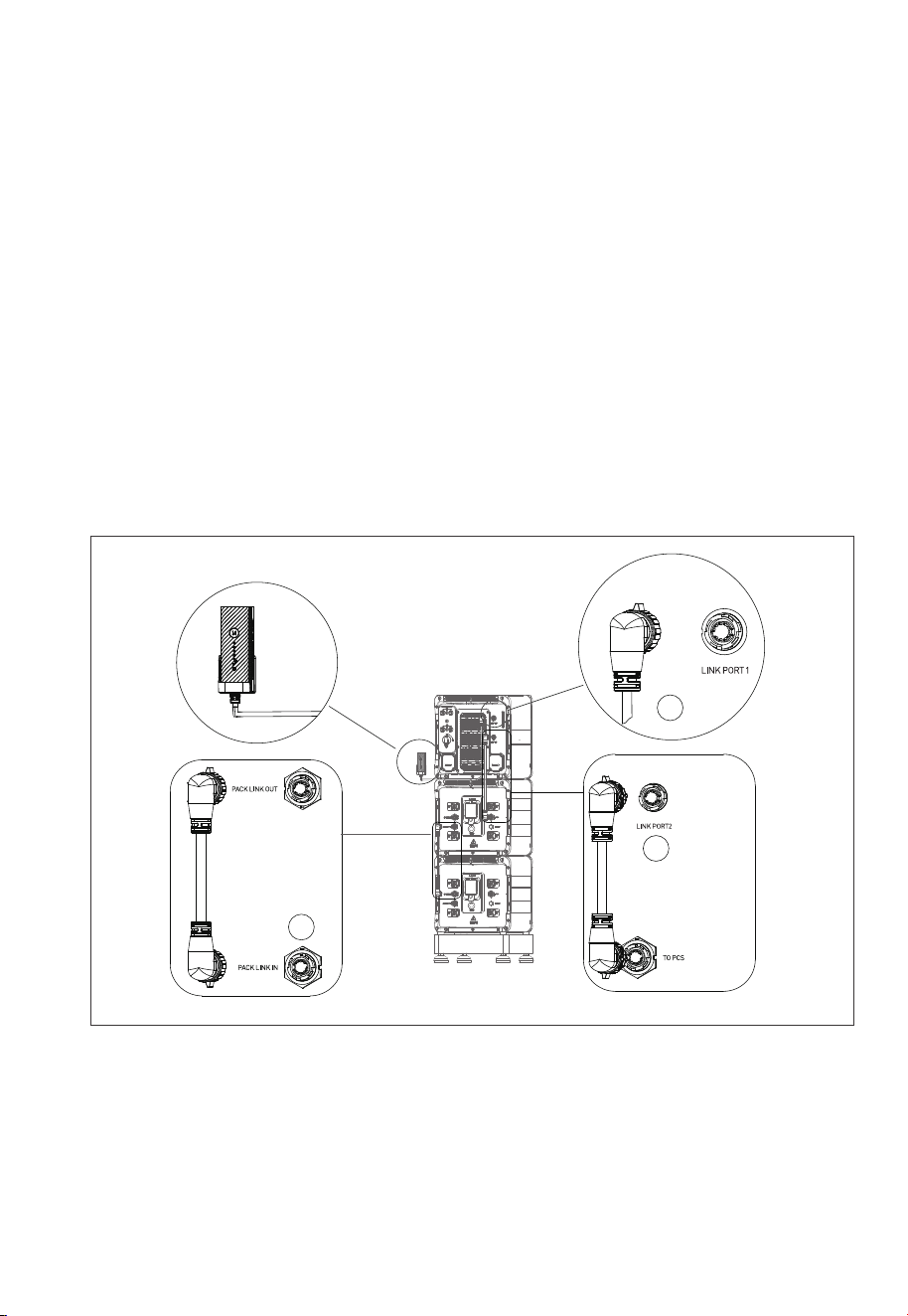
6.6.5 Communication Cable
Step1:
To achieve communication between two B500 battery packs, a communication
cable is required. Plug one end of the cable to the B500 Link-in port, and the other
to the upper B500’s Link-out port. See Fig. 6-11 “①”.
Step2:
For communication between the EP800 inverter and B500 battery packs, plug one
end of the communication cable to the top B500’s inverter signal port (To Pcs), and
the other to the Link Port 2 of the EP800 inverter. See Fig. 6-11 “②”.
Step3:
Connect the IoT controller to the EP800 inverter. See Fig. 6-11 “③”.
Note: For how to integrate multiple B500s to the EP800, please refer to Fig. 6-8.
Figure 6-11
JUST POWER ON 57
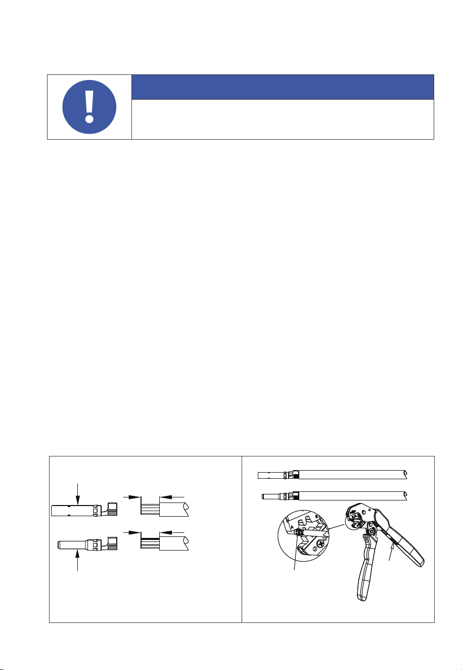
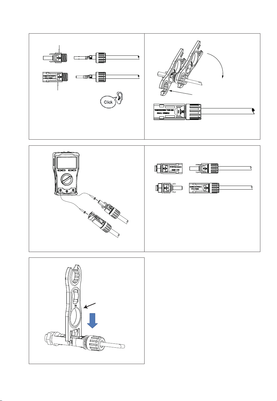
Step 1: It is recommended to use 12AWG outdoor power cable for PV1 and 10AWG
outdoor power cable for PV2. Disconnect the cable connector from the EP800
positive and negative connectors. (You’re strongly recommend to distinguish the
positive and negative connectors with different colors.)
Step 2: Use wire strippers to peel off the insulation layer of the positive and negative
power cables. For the specific stripping length, refer to Fig. 6-12-1.
Step 3: Insert the positive and negative power cables into the positive and negative
metal terminals separately. Crimp them tightly to ensure that the cable can not be
pulled out. See Fig. 6-12-2.
Step 4: Insert the crimped positive and negative power cables through the locking
nut and into the corresponding plastic housing until you hear a click, which
indicates that the metal core has been snapped into place, and then tighten the
locking nut. See Fig. 6-12-3 and Fig. 6-12-4.
Step 5: Use a multimeter to confirm the positive and negative poles. See Fig. 6-12-5.
The positive and negative connectors can then be inserted into the PV input of
EP800 inverter. See Fig. 6-12-6.
If you need to remove the PV positive and negative connectors from the inverter,
use a removal crimper to insert the bayonet as shown in Fig. 6-12-7, and press down
to remove the connectors.
6.6.6 PV Cables
Attention
Before removing the PV input positive and negative connectors,
make sure the DC switch on the inverter has been set to “OFF”.
Figure 6-12-1 Figure 6-12-2
1. Positive metal core
2. Negative metal core
0.276-0.354(in)
/7-9(mm)
0.276-0.354(in)
/7-9(mm)
2
1
Crimper
Press
JUST POWER ON58
1. Positive metal terminal
MC4 Wrench
2. Negative metal terminal
Remove the PV connector
1
2
Figure 6-12-5
Figure 6-12-7
Figure 6-12-6
Figure 6-12-3 Figure 6-12-4
JUST POWER ON 59
0.8in
M6 Screws Max.
Torque: 3.0N m
(26.55 in-lbs)
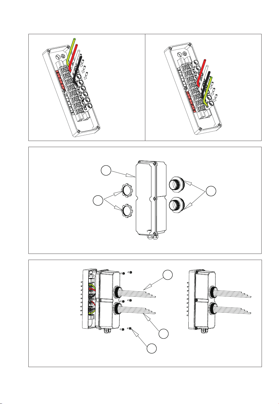
6.6.7 GRID and BACKUP Cables
Prerequisite: Prepare neutral, live, and grounding wires (recommended colors:
white, black, green; use 6AWG/6AWG outdoor power cables).
Step 1: Select the appropriate type and size of cables (see table 7-2). Strip the cables
with a length of 0.8 inches, as shown in Fig. 6-13-1.
Step 2: Install the terminal block onto the junction box's terminal strip, as shown in
Fig. 6-12-2.
Step 3: Connect the 6AWG BACKUP cable as labeled (G, L1, N, L2) in the BACKUP
section of the junction box. Secure it using a hex wrench, as shown in Fig. 6-13-3/6-13-4.
Step 4: Connect the 6AWG GRID cable as labeled (L1, N, L2, G) in the GRID section of
the junction box. Secure it with a hex wrench, as shown in Fig. 6-13-5.
Step 5: Attach the PG waterproof connector to the AC cable protection case. Tighten
the hexagon nut at the bottom of the connector with a socket tool, as shown in Fig.
6-13-6.
Step 6: Pass the DRMs cable through the PG conductor, as shown in Fig. 6-13-7.
Step 7: To complete the installation, pass the fitting through the waterproof hose
and insert the BACKUP and GRID cables into the hose. Tighten the fitting to the
protection case as shown in Fig. 6-13-8.
Figure 6-13-2
Figure 6-13-1
Figure 6-13-3
JUST POWER ON60
Figure 6-13-5Figure 6-13-4
Figure 6-13-6
Figure 6-13-7
Fig. 6-13 Load cable connection
AC cable protection case
Ύ W aterproof hose fitting
ΏWaterproof hose(3/4 inch)
BACKUP cables
ΎGRID cables
ΏM4*12 screws, Max. Torque: 1.2N m(10.62 in-lbs)
1
2
3
1
2
3
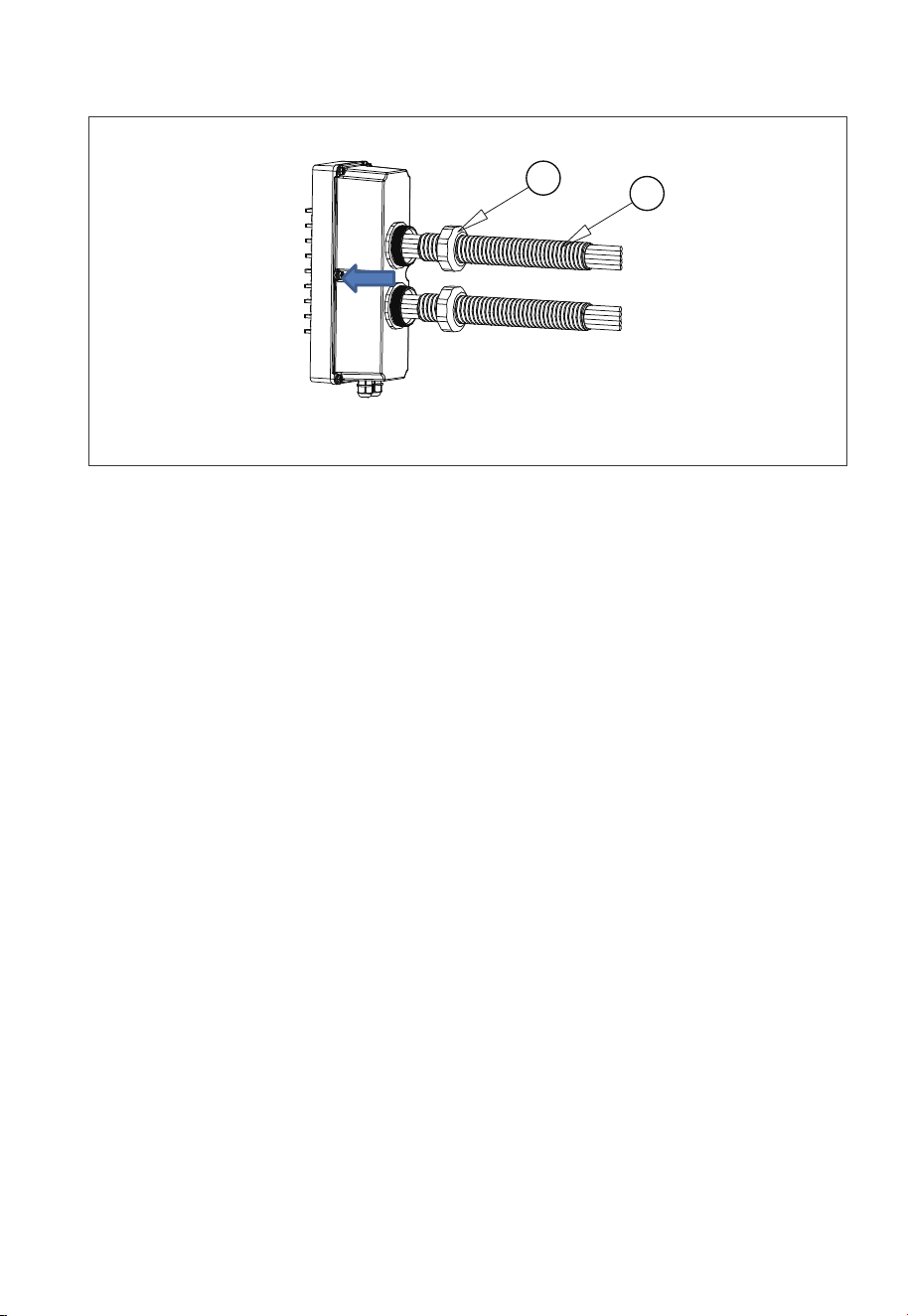
JUST POWER ON 61
Waterproof hose fitting
Ύ Waterproof hose
1
2
Figure 6-13-8
7.1 Preliminary Check
Check the followings before first use.
• Confirm that all components of the system are installed according to specific
requirements.
• Make sure the PV+ / PV- and BAT+ / BAT- cables are connected with correct polarity
and proper voltage.
• Switch off all AC and DC circuit breakers.
• Circuit breakers should be selected according to the requirements of this manual
and local regulations.
• Make sure grid and load cables are held firmly in place.
• All safety signs and warning labels shall be firmly attached and clearly visible when
needed.
7. System Check

JUST POWER ON62
7.2 Commissioning
Step 1: Switch on the DC circuit breakers on B500 battery packs. Press and hold the
power button on any B500 for 3 seconds, the button lights up green.
Step 2: Wait for about 40 seconds till the inverter indicator keeps steady green.
Step 3: Switch on the AC circuit breakers and rapid shut down switch connected to
the inverter GRID terminal.
Step 4: Switch on the DC power on EP800.
Step 5: Turn on “System Switch” in the BLUETTI App. For details, please refer to
BLUETTI App User Manual.
Step 6: Check the output voltage of BACKUP terminal.
Step 7: Switch on the AC circuit breakers connected to the inverter BACKUP
terminal.
Step 8: Check the EP800 system status through the App.
7.3 Decommissioning
Step 1: Turn off the “System Switch” on BLUETTI App.
Step 2: Switch off the AC circuit breakers connected to the inverter GRID and
BACKUP terminals.
Step 3: Switch off the DC power of the inverter.
Step 4: Press the circular power button on any B500, the button light flashes green.
Step 5: The indicator continues to flash.
Step 6: When the indicator is off, B500 battery packs turn off.
Step 7: Switch off main switches for all B500 and the EP800 powers off.
Warning
There is still residual voltage after the EP800 is powered off, which
may cause electric shock or burns. Please wait at least 30 minutes
before operating the system.
Warning

JUST POWER ON 63
8. System Maintenance
8.1 USB Firmware Upgrade
The EP800 inverter supports firmware upgrades via a USB drive to optimize its
performance and avoid failures caused by firmware errors.
Step 1: Connect the USB drive to a USB port on your computer.
Step 2: Download the upgrade file*, unzip and store it on the USB drive.
Step 3: Connect the USB drive to the USB port on EP800.
Step 4: Power on EP800.
Step 5: The firmware upgrade starts automatically once the upgrade files are
detected.
Step 6: The buzzer beeps after the firmware is updated successfully. Please unplug
the USB drive, or EP800 will report a USB Format Error.
Step 7: Pair EP800 with BLUETTI App, then you can check the current firmware
version. If any of the following occurs, please try the solutions provided. If the
symptom persists after 5 attempts, contact the BLUETTI support team.
* Please contact our company for further assistance.
8.2 OTA Firmware Upgrade
The EP800 also supports OTA firmware upgrade. For details, please refer to the
“Upgrade” section within the “Basic Settings” of the EP800 Home Energy Storage
System BLUETTI App User Manual.
Error Description
USB Upgrade Failed. Please contact the BLUETTI support team.
1.Make sure the USB is formatted as FAT32 with no
more than 32G in size.
2.Check if the upgrade files exist or expire. Please
download the latest upgrade files.
Please download the latest upgrade files. If the
symptom persists, contact the BLUETTI support team.
USB Format Error
Firmware version not
updating or abnormal.
Troubleshooting
Table 8-1

JUST POWER ON64
9. System Disposal
9.1 Remove the Inve
rter
When the inverter is no longer in use, it must be disposed of properly.
Step 1: Power off the system.
Step 2: Disassemble all electrical connections to the inverter, such as signal cable,
DC input cable, power cable, AC input cable, grounding cable, etc.
Step 3: Remove the inverter and related parts.
9.2 Recycle the Inverter and Battery Pack
When the battery pack reaches the end of its lifespan,itmust be safely and carefully
disposedofby the provisions of local laws andregulations.
Please contact our company for further assistance if the battery pack is
a.Leaked or damaged.
b.Severely degraded in performance.
c.To be replaced or not intended for further use.

JUST POWER ON 65
10. Specifications
Protection
Output overcurrent protection
Output short-circuit protection
Over temperature protection
Overload
100%-110% of rated power, 10min;
110%-150% of rated power, 10s.
Note
Off-grid Load Output
Item
Rated Output Power
Output Voltage
Output Current
Output Frequency
Inversion Efficiency
Output Voltage THD
Crest Factor (CF)
Maximum Number of Parallel Units
Description
7680W
120V / 240V
32A
60Hz
94% Max.
<3%
3:1
2
Pure resistive load
Grid Input
Item
Wiring
Rated Voltage
Voltage Range
Input Frequency Range
Maximum Input Apparent Power
Maximum Input Current
Maximum Input Power
Power Factor (PF)
Current Total Harmonic Distortion (THD)
On and Off-Grid Switching Time
Grid Charging Efficiency
Description Note
L1/L2/N/G
120VAC / 240VAC
110V-126V / 220V-252V
55Hz-65Hz
12000VA
50A
7680W
1.0
<3%
<20ms
94% Peak
Bypass + Grid Charging
Bypass + Grid Charging
Grid Charging
Grid Charging
10.1 AC Port

JUST POWER ON66
PV Input
Item
Maximum Input Power
Array In Series
Maximum Input Voltage
MPPT Voltage Range/Rated
Single MPPT Maximum Input Current
Single MPPT Maximum Short-circuit Current
MPPT Efficiency
PV Inversion Efficiency
Description Note
9000W
1/2
550V
150V-500V / 360V
12.5A / 25A
15A / 30A
99.9%
96.0% Peak
PV Input
10.2 DC Port
Reverse polarity protection
Insulation resistance
detection Arcing detection
Protection
Battery
Item
Battery Model
Number of Parallel Units
Charging Strategy
Description Note
B500
2-4
BMS Orders (CC / CV)
When there are only
two units connected,
the input power is lower.
9000W
Maximum Input Power
3000W+ 6000W
(With 2 battery packs:
Managed flexibly by BMS)
MPPT Channel 2

JUST POWER ON 67
AC (Grid-tied)
Item
Relative Humidity
Static Power
Standby Power
Operating Ambient Temperature Range
Noise Emission (dB)
Cooling
Ingress Protection (IP) Rating
Working Altitude
Net Weight
Communication
Warranty
Description Note
5%-95%
18W
35W
4°F to 104°F / -20°C to 40°C
≤50dB (A)
Forced air cooling
NEMA 4X / IP65
≤6561ft / 2000m
105lbs / 48kg
USB / WiFi / Bluetooth
10 years
General
25.0in × 12.8in × 14.6in
/ 636mm × 325mm × 370mm
Dimensions (L*W*H)

JUST POWER ON68
11. Troubleshooting
Error DescriptionNo. Troubleshooting
B001.
B002.
B003.
B004.
B005.
B006.
B007.
B008.
B009.
B010.
B011.
B012.
B013.
B014.
B015.
B016.
B017.
B018.
B019.
B020.
B021.
BUS Overvoltage
BUS2 Overvoltage
BUS Undervoltage
BUS2 Undervoltage
Hardware BUS Overvoltage
Hardware BUS2 Overvoltage
Hardware Battery Overvoltage
Hardware Inverter Overcurrent
Hardware Inverter2 Overcurrent
Hardware LLC1 Input Overcurrent
Hardware LLC2 Input Overcurrent
Reserved
Auxiliary Power Undervoltage
DC Component Exception
Relay Failure
PV Connection Error
PV1 Overcurrent
PV2 Overcurrent
PV1 Voltage High
PV2 Voltage High
1. Log in to the App and bind your EP800.
Connect to it via Bluetooth to check for
any firmware updates.
2. After successfully upgrading, restart
your EP800*. If the issue persists, please
contact BLUETTI support for assistance.
* See FAQ 1.
1. Log in to the App and bind your EP800. Connect to it
via Bluetooth to check for any firmware updates.
2. Make sure the input currents for PV1 and PV2 are
below 12.5A and 25A, respectively. You can monitor the
real-time current in the App.
3. Restart your EP800*. If the issue persists, please
contact BLUETTI support for assistance.
* See FAQ 1.
1. Immediately turn off the PV input switch. Check if the
total open circuit voltage is within 500V. If it exceeds
the limit, reduce the number of PV modules connect-
ed in series.
2. The inverter will automatically resume normal
operation after the necessary corrections.
3. Restart your EP800*. If the issue persists, please
contact BLUETTI support for assistance.
* See FAQ 1.
Reserved

JUST POWER ON 69
B022.
B023.
B024.
B025.
B026.
B027.
Reserved
PV1 ISO Failure
PV2 ISO Failure
Reserved
Hardware PV1 Failure
Hardware PV2 Failure
B031.
B032.
B033.
Restart your EP800*. If the issue persists, please
contact BLUETTI support for assistance.
* See FAQ 1.
1. Log in to the App and bind your EP800. Connect to it
via Bluetooth to check for any firmware updates.
2. Make sure the total open circuit voltage of your PV
modules doesn’t exceed 500V, and the operating
currents for PV1 and PV2 stays within 12.5A and 25A,
respectively. You can monitor the PV input in real time
in the App. If the voltage exceeds the limit, reduce the
number of PV modules connected in series.
3. The inverter will automatically resume normal
operation after the necessary corrections.
4. Restart your EP800*. If the issue persists, please
contact BLUETTI support for assistance.
* See FAQ 1.
1. When installing for the first time, make sure to
connect the mains' L1 and L2 phases correctly to the
GRID terminals of the EP800.
2. Switch on or off both two phases of the mains
simultaneously.
3. Restart your EP800*. If the issue persists, please
contact BLUETTI support for assistance.
* See FAQ 1.
1. Check if the EP800 inverter’s fan is spinning properly.
Log in to the App and bind your EP800. Connect to it
via Bluetooth to check for any firmware updates.
2. After successfully upgrading, restart your EP800*. If
the issue persists, please contact BLUETTI support for
assistance.
* See FAQ 1.
1. Check if the EP800 inverter’s fan is spinning properly.
Log in to the App and bind your EP800. Connect to it
via Bluetooth to check for any firmware updates.
2. After successfully upgrading, restart your EP800*. If
the issue persists, please contact BLUETTI support for
assistance.
* See FAQ 1.
1. Check if the EP800 inverter’s fan is spinning properly.
Log in to the App and bind your EP800. Connect to it
via Bluetooth to check for any firmware updates.
2. After successfully upgrading, restart your EP800*. If
the issue persists, please contact BLUETTI support for
assistance.
* See FAQ 1.
Reserved
Phase Sequence Error
Fan Failure
Zero Drift Abnormal
(Sampling zero abnormal)
Hardware Input Overcurrent
DC Input Voltage Low
DC Input Voltage High
B034.
B035.
B036.
DC Input Overcurrent
LLC Output Overvoltage
LLC2 Output Overvoltage
B037.
B038.
B039.
B028.-
B030.

JUST POWER ON70
B040.
B041.
B042.
B043.
B044.
B045.
B046.
B047.
B048.
B049.
B050.
B051.
B052.
B053.
B054.
B055.
B056.
B057.
B058.
B059.
Inverter Overload
L2 Inverter Overload
1. Disconnect the loads on the GRID terminals while
keeping the BACKUP operation normal. Check the
power and current of the two phases on the BACKUP
terminals. If they exceed the limits and trigger an alarm,
reduce the connected loads accordingly.
2. Restart your EP800*. If the issue persists, please
contact BLUETTI support for assistance.
* See FAQ 1.
1. Log in to the App and bind your EP800. Connect to it
via Bluetooth to check for any firmware updates.
2. After successfully upgrading, restart your EP800*. If
the issue persists, please contact BLUETTI support for
assistance.
* See FAQ 1.
1. Make sure the EP800 is placed in a well-ventilated
environment.
2. Allow the EP800 to cool down and then restart*. If the
issue persists, please contact BLUETTI support for
assistance.
* See FAQ 1.
1.Make sure all connection are secure.
2. Restart your EP800*. If the issue persists, please
contact BLUETTI support for assistance.
* See FAQ 1.
1.Make sure all connection are secure.
2. Restart your EP800*. If the issue persists, please
contact BLUETTI support for assistance.
* See FAQ 1.
1.Make sure all connection are secure.
2. Restart your EP800*. If the issue persists, please
contact BLUETTI support for assistance.
* See FAQ 1.
1. Make sure the EP800 is placed in a well-ventilated
environment.
2. Restart your device*. If the issue persists, please
contact BLUETTI support for assistance.
* See FAQ 1.
Reserved
L1 Inverter Output Failure
L2 Inverter Output Failure
L3 Inverter Output Failure
Overtemperature Protection
Communication Failure
Reserved
DSP Communication Interrupted
BMS Communication Interrupted
IoT Communication Interrupted
Zero Drift Abnormal-ARM
RTC Read and Write Abnormal
Inverter Leakage Current High
Temperature 1 Abnormal
Temperature 2 Abnormal
Temperature 3 Abnormal
Temperature 4 Abnormal
Operating Ambient
Environment Abnormal

JUST POWER ON 71
B060.
B061.
B062.
B065.
BMS Charge Protection
BMS Discharge Protection
BMS System Failure
Reserved
PV Input Voltage Too High
B066.
B067.
B068.
B069.
LLC Output Voltage Low
BUS Soft Start Abnormal
Parallel Configuration Error
Parallel Communication Loss
Reserved
B097.
B098.
B099.
B100.
B101.
B102.
Grid Voltage High
Grid Voltage Low
Grid Frequency High
Grid Frequency Low
Grid Oscillation
Grid Loss
1. Make sure the EP800 is placed in a well-ventilated
environment.
2. Restart your device*. If the issue persists, please
contact BLUETTI support for assistance.
* See FAQ 1.
1. Immediately turn off the PV input switch. Check if
the total open circuit voltage is within 500V. If it
exceeds the limit, reduce the number of PV modules
connected in series.
2. The inverter will automatically resume normal
operation after the necessary corrections.
3. Restart your EP800*. If the issue persists, please
contact BLUETTI support for assistance.
* See FAQ 1.
1. Log in to the App and bind your EP800. Connect to it
via Bluetooth to check for any firmware updates.
2. After successfully upgrading, restart your EP800*. If
the issue persists, please contact BLUETTI support for
assistance.
* See FAQ 1.
1. Log in to the App and bind your EP800. Connect to it
via Bluetooth to check for any firmware updates.
2. Inspect the parallel configuration parameters in the App.
3.Check if the system wiring is properly installed and
connected, especially the parallel communication cable.
4. Restart your EP800*. If the issue persists, please
contact BLUETTI support for assistance.
* See FAQ 1.
1. Check if the grid voltage and frequency are within the
normal range. If the issue occurs occasionally, it may be
due to abnormal working conditions of the grid. The
inverter will recover once the grid returns to normal.
2. If the issue happens frequently, consult your utility
company to confirm if the voltage and frequency are
within the normal range. If they are, and your
connections are secure, restart the EP800* and enable
the Grid Self-adaption Mode in Advanced Settings. If
the issue persists, please contact BLUETTI support for
assistance.
* See FAQ 1.
B063.-
B064.
B070-
B096

JUST POWER ON72
B103.
B104.
B129.
B134.
B135.
B137.
B138.
B136.
B141.
B142.
B143.
B146.
B147.
PV1 Voltage Low
PV2 Voltage Low
Reserved
Reserved
USB Format Error
USB Upgrade Abnormal
USB Communication Abnormal
USB No Upgrade File
Arcing Detection Abnormal
Reserved
Arcing Module Self-Test Failure
Arcing Module Communication Failure
Data Clearing in Progress
Reserved
Excessive Relay Switching Today
1. Make sure the total open circuit voltage is higher
than 200V. You can check this in the App. If it’s lower,
add more PV modules in series.
2. The inverter will automatically resume normal
operation after the necessary corrections.
3. It’s normal to receive this alarm when the sun is less
intense, especially in the morning and evening.
4. Restart your EP800*. If the issue persists, please
contact BLUETTI support for assistance.
* See FAQ 1.
1. Log in to the App and bind your EP800. Connect to it
via Bluetooth to check for any firmware updates.
2. After successfully upgrading, restart your device*. If
the issue persists, please contact BLUETTI support for
assistance.
* See FAQ 1.
1. Check if there are any available upgrade files. If
needed, contact BLUETTI support for assistance.
2. Make sure the USB is formatted as FAT32 and its
maximum memory is 32G.
3. Restart your EP800*. If the issue persists, please
contact BLUETTI support for assistance.
* See FAQ 1.
1. Log in to the App and bind your EP800. Connect to it
via Bluetooth to check for any firmware updates.
2. After successfully upgrading, restart your EP800*. If
the issue persists, please contact BLUETTI support for
assistance.
* See FAQ 1.
1. Log in to the App and bind your EP800. Connect to it
via Bluetooth to check for any firmware updates.
2. After successfully upgrading, restart your EP800*. If
the issue persists, please contact BLUETTI support for
assistance.
* See FAQ 1.
While the EP800 operates, it manages the system’s
built-in relays automatically. To prolong the system
lifespan, the system is programmed to track the
number of relay switches. When you receive this alert,
it means that the relay switches have reached the
maximum allowed for the current day or time period.
However, the count will reset automatically when a
new day (or time period) begins.
EEPROM Read and
Write Abnormal
Excessive Relay Switching
at this Moment
B105.-
B128.
B130-
B133.
B139-
B140.
B144-
B145.

JUST POWER ON 73
How to restart the EP800?
1. Switch off the system:
a.Open the App and turn off the System Switch.
b.Disconnect the PV and Grid switches.
c.If you need uninterrupted power for your BACKUP loads, turn the transfer
switch of the sub-panel to Grid.
d.Press and hold the power button on any B500 unit for about 3 seconds until
the button light starts flashing.
e.Wait for the green light on the EP800 inverter to turn off, indicating that the
entire system is now powered off.
f.Make sure to turn off all the power switch on the B500 units.
2. Restart:
a.Turn on all B500 unit’s power switch.
b.Press and hold the power button on any B500 unit for about 3 seconds until
the button light starts flashing.
c.When the EP800 light is on, the entire system is switched on.
d.In the App, turn on the System Switch.
e.Switch on the PV and Grid switches. Turn the transfer switch of the sub-panel
to Backup.
Why can’t I connect it via Bluetooth?
Please follow the steps below to troubleshoot the issue:
1. Check if the IoT controller is properly connected.
2. Make sure you've granted the App access to use Bluetooth.
3. Enable Bluetooth on your phone.
4. Grant the App access to your phone's location service.
If the issue persists, please contact BLUETTI support for further assistance.
Why can’t I connect it remotely via Cloud?
Please follow the steps below to troubleshoot the issue:
1. Check if the IoT controller is properly connected.
2. Configure a WiFi network for the EP800.
3. Make sure you've input correct WiFi password and match the specific
character requirements .
4. Check if the WiFi is operating within the 2.4GHz band. The EP800 supports
2.4GHz WiFi only.
If the issue persists, please contact BLUETTI support for further assistance.
12. FAQs (Frequently Asked Questions)
Q1:
A:
Q2:
A:
Q3:
A:

JUST POWER ON74
Why aren't the devices connected to the BACKUP side receiving any power?
Please follow these self-check steps first:
1. Make sure you have turned on the System Switch in the App.
2. If the B500 batteries have run out of power and both the PV and Grid
switches are off, the system automatically disables the power output to protect
the batteries.
If the issue persists, please contact BLUETTI support for further assistance.
How long does it take to start the entire system?
Typically, it takes a maximum of 3 minutes to start the system. However, the
duration may vary depending on how you initiate the system. If you encounter
any issues or have any questions about using the EP800, please feel free to
contact BLUETTI support.
Can I connect a 12kWp solar system to the EP800, even if it exceeds the PV
input power? Will the EP800 automatically adjust the PV input current?
Whether you can connect a 12kWp solar system to the EP800 depends on the
voltage of your solar setup. The EP800 can work with solar systems that have an
open-circuit voltage ranging from 150V to 500V. It's able to accommodate two
PV inputs, with a total power of 9,000W (3kW for PV1 and 6kW for PV2). The
EP800 can automatically adjust the input current to stay within these limits,
but it won't exceed 12.5A for PV1 and 25A for PV2.
Can it charge and discharge at the same time?
Yes. The EP800 supports pass-through charging.
Can my household appliances be powered by solar panels while they are
charging the battery?
Yes, in the "Self-consumption" mode, the EP800 prioritizes solar power for
running household appliances, and any extra energy is used to charge the
battery.
How does the EP800 power my household appliances? Does it use solar power
first and then switch to grid power when needed?
You can configure the EP800 to operate in "Self-consumption" mode. In this
mode, the EP800 prioritizes solar energy for running household appliances. If
there's not enough solar power available, the EP800 combines it with stored
energy from the battery to power your appliances. Only if there's still not
enough power, it will draw electricity from the grid to meet your demand.
Q4:
A:
Q5:
A:
Q6:
A:
Q7:
A:
Q8:
A:
Q9:
A:

JUST POWER ON 75
Why isn't my solar system able to charge the EP800?
Please follow these self-check steps:
1: Make sure the PV switch of the EP800 is in the "ON" position.
2: Check the connections of your solar panels and the PV input cables.
3: Check if there are any PV-related error messages in the App.
4: Make sure you've turned on the System Switch in the App.
If the issue persists, please contact BLUETTI support for further assistance.
How can I upgrade the EP800 firmware?
To upgrade the firmware of your EP800, follow these steps:
1.Log in to the App and bind your EP800.
2.Connect to the EP800 via Bluetooth.
3.In the App, navigate to the Firmware Upgrade section.
4.Select the option to upgrade the firmware
Without logging in and binding your EP800, you won't find the upgrade
option, even if connected to WiFi.
What if the B500 battery pack's circuit breaker automatically trips and cuts off
the power?
Please don't manually reset it, and contact BLUETTI support for assistance.
What should I do if the SoC readings seem to be inaccurate?
Please try these steps to address the issue:
1.Use the App to update to the latest software for the BMS.
2.Fully charge and discharge your EP800 twice.
This will help recalibrate the system and restore accurate SoC readings.
Why doesn't the App show the load power?
The App is designed to display the load power only when it exceeds 100W for
each phase.
If I set the SoC low value to 5%, will the EP800 shut down due to overnight
self-discharge?
No, the EP800 can automatically recharge from the grid and maintain a
minimum SoC of 4% to ensure the system doesn't shut down.
Q10:
A:
Q11:
A:
Q12:
A:
Q13:
A:
Q14:
A:
Q15:
A:

JUST POWER ON76
What should I keep in mind when setting the charging and discharging time?
When setting the charging and discharging time, it's important to note the
following:
1. Arrange the time periods in chronological order, starting with the earliest and
ending with the latest.
2. Avoid time periods that span into the next day.
Why does the solar panel stop working when the battery is full, even if there are
devices using power?
This is completely normal. If there are fluctuations in the power usage while the
solar panel is charging the battery, it can temporarily stop to prevent overcharg-
ing. As soon as the battery's power level decreases while running devices, the
solar panel will automatically start working again.
How can I share access to the EP800 with others?
If you want to invite other BLUETTI App users to control the EP800, please
follow the steps below:
1.Open the App and go to Settings.
2.Select the Share Device option and generate the QR code.
3.Have others scan the QR code using the BLUETTI App.
Please note that the QR code is valid for 10 minutes and you can share access
with up to 5 accounts simultaneously.
How can I set the EP800 as a backup power source?
The EP800 is designed to operate in Backup UPS mode by default, providing a
reliable home backup power source that kicks in only when the grid fails.
To activate this mode, access the Settings menu, navigate to Working Mode,
and select the Backup mode.
How can I optimize solar energy usage and achieve energy self-sufficiency?
You can enable the Self-consumption mode on the EP800. In this mode, the
EP800 prioritizes direct consumption of solar energy for immediate household
needs and stores excess energy in the battery for later use. With such a strategy,
the EP800 ensures an efficient and reliable power supply, reducing reliance on
the grid and promoting energy independence.
To enable this mode, access the Settings menu, navigate to Working Mode, and
select the Self-consumption mode.
Q16:
A:
Q17:
A:
Q18:
A:
Q19:
A:
Q20:
A:

JUST POWER ON 77
My utility provider offers a Time of Use (TOU) electricity tariff. How can I use the
EP800 to save on peak electricity costs?
You can configure the Time of Use mode to fit your specific needs. During the
charge period, the EP800 draws power from the grid, typically during off-peak
tariff hours when electricity rates are lower, to replenish its energy storage and
discharges during peak hours.
To set this mode, please follow the steps below:
1.Go to the Advanced Settings and turn on the Charge From Grid.
2.Go to the Settings menu, tap on Working Mode, and select Time of Use.
3.Tap on Manage Charge/Discharge Time and designate time periods with
lower electricity rates as Off-Peak and higher rate periods as Peak.
Note: A maximum of 6 time periods can be set, with the earliest as the first and
the latest as the last.
Can I power on the B500 unit separately by pressing its power button?
Yes, you can.
Can I charge the EP800 using a generator?
We recommend using a generator with a voltage greater than 240V and a
power greater than 5000W to charge the EP800.
Can I install the EP800 outdoors?
Absolutely, the EP800 is equipped with a NEMA 4X protection rating. However,
if you plan to install it in a location that is directly exposed to sunlight, it is
advisable to purchase a separate power shelter from BLUETTI's official website.
This will provide additional protection and ensure the EP800 operates safely,
reliably, and efficiently in all weather conditions.
Q21:
A:
Q22:
A:
Q23:
A:
Q24:
A:

JUST POWER ON78
This equipment has been tested and found to comply with the limits for a Class B
digital device, pursuant to part 15 of the FCC Rules. These limits are designed to
provide reasonable protection against harmful interference in a residential installa-
tion. This equipment generates, uses and can radiate radio frequency energy and, if
not installed and used in accordance with the instructions, may cause harmful
interference to radio communications. However, there is no guarantee that interfer-
ence will not occur in a particular installation. If this equipment does cause harmful
interference to radio or television reception, which can be determined by turning the
equipment off and on, the user is encouraged to try to correct the interference by
one or more of the following measures:
—Reorient or relocate the receiving antenna.
—Increase the separation between the equipment and receiver.
—Connect the equipment into an outlet on a circuit different from that to which the
receiver is connected.
—Consult the dealer or an experienced radio/TV technician for help.
FCC RF Exposure Warning Statement:
This equipment.complies with FCC radiation exposure limits set forth for an uncon-
trolled environment. This equipment shall be installed and operated with minimum
distance 20cm between the radiator & body
Please note that changes or modifications of this product is not expressly approved
by the party responsible for compliance could void the user's authority to operate
the equipment
13. FCC Warning

JUST POWER ON 79
IC
This device contains licence-exempt transmitter(s)/receiver(s) that comply with
Innovation, Science and Economic Development Canada’s licence-exempt RSS(s).
Operation is subject to the following two conditions:
(1) This device may not cause interference.
(2) This device must accept any interference, including interference that may cause
undesired operation of the device.
L’émetteur/récepteur exempt de licence contenu dans le présent appareil est
conforme aux CNR d’Innovation, Sciences et Développement économique Canada
applicables aux appareils radio exempts de licence. L’exploitation est autorisée aux
deux conditions suivantes :
(1) L' appareil ne doit pas produire de brouillage;
(2) L' appareil doit accepter tout brouillage radioélectrique subi, même si le brouil-
lage est susceptible d' en compromettre le fonctionnement.
Radio Frequency Exposure Statement for IC
This equipment complies with IC exposure limits set forth for an uncontrolled
environment. This equipment shall be installed and operated with minimum
distance 10cm between the radiator & body.
Cet équipement est conforme aux limites d'exposition IC définies pour un
environnement non contr?lé. Cet équipement doit être installé et utilisé avec une
distance minimale de 10cm entre le radiateur et la carrosserie.
CAN ICES-3 (B) / NMB-3 (B)
This Class B digital apparatus complies with Canadian ICES-003.
(Cet appareil numérique de la Classe B conforme à la norme NMB-003 du Canada).

@ BLUETTI Support
@ BLUETTI Official
@bluetti.inc@ bluetti_inc @bluetti_official [email protected]
For more information, please visit:
Customer Service
Tel: 800-200-2980 (Monday to Sunday 9:00-17:00)
Mail: sale@bluettipower.com (Pre-sales), service@bluettipower.com (After-sales)
Web: https//www.bluettipower.com
Add: 6185 S Valley View Blvd Ste D.Las Vegas,NV 89118.
P/N:17.0303.0586-03A3