

EP900
Energy Storage System
User Manual V2.3
Please Read This Manual Before Use And Follow Its Guidance.
Keep This Manual For Future Reference.


Thank You!
Thank you for making BLUETTI a part of your family.
From the very beginning, BLUETTI has tried to stay true to a sustainable future
through green energy storage solutions while delivering an exceptional
eco-friendly experience for our homes and our world.
That's why BLUETTI makes its presence in 100+ countries and is trusted by
millions of customers across the globe.
France
Germany
Netherlands

Copyright © 2024 ShenzhenPowerOakNewenerCo., Ltd. All rights reserved.
No part of this document may be reproduced or transmitted in any form or by any
means without the prior written consent of Shenzhen˜PowerOak˜Newener˜Co.,
Ltd.
Notice
BLUETTI's products, services, and features are subject to the agreed-upon terms
and conditions during purchase. Please note that some products, services, or
features described in this manual may not be available under your purchase
contract. Unless otherwise specified in the contract, BLUETTI makes no repre-
sentations or warranties of any kind, express or implied, with respect to the con-
tents of this manual.
The contents of this manual are subject to change without notice. Please get
the latest version from: https://www.bluettipower.com/pages/user-guides
If you have any questions or concerns about this manual, please contact
BLUETTI support for further assistance
Shenzhen˜PowerOak˜Newener˜Co., Ltd.
F19, BLD No.1, Kaidaer, Tongsha RD No.168, Xili street, Nanshan, Shenzhen, China
Web: https://www.bluettipower.com

About the Manual
Purpose
This user manual describes the installation, electrical connection, commission-
ing, maintenance and troubleshooting of EP900 Home Energy Storage System
(hereinafter referred to as EP900). Please read and understand all instructions
in this manual before use.
Target Audience
• Installation, operation, and maintenance technicians
• End-user
Symbol Conventions
This manual uses the following symbols to highlight important information:
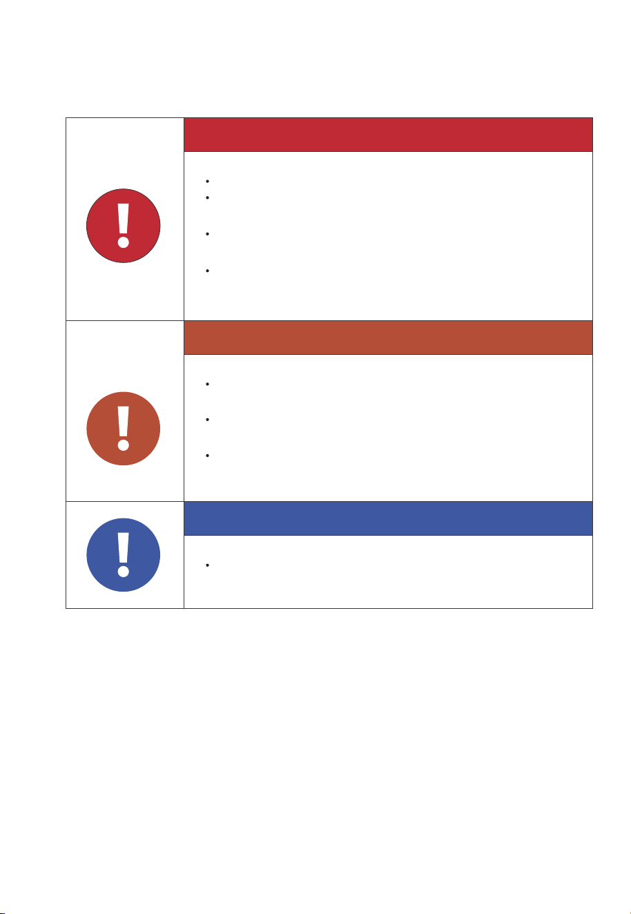
Danger
Warning
Caution
Attention
Instruction
It indicates a hazardous situation which, if not avoided, will result
in death or serious injury.
It indicates a hazardous situation which, if not avoided, could
result in death or serious injury.˜
It indicates a hazardous situation which, if not avoided, could
result in minor or moderate injury.
It indicates a potentially hazardous situation which, if not
avoided, could cause substantial damage to property and the
environment.
It contains important additional information as well as useful
tips for safe, efficient and hassle-free operation of the EP900
home energy storage system.

Safety Guideline
Safety Instructions
Installation Safety
Battery Safety
Electrical Safety
Maintenance Requirements
Transportation Requirements
Storage Requirements
Handling Requirements
Label Description
EP900 Home Energy Storage System
Introduction
Working Mode
EP900 Home Energy Storage Inverter
EP900 Inverter Overview
LED Indicators
Buzzer Alarm
Maintenance and Care
B500 Battery
Introduction
Overview
LED Indicators
Maintenance and Care
IoT Controller
Communication Principle
Overview
Installation
Safety Instructions
Connection and Operations
Contents
1
1.1
1.2
1.3
1.4
1.5
1.6
1.7
1.8
1.9
2
2.1
2.2
3
3.1
3.2
3.3
3.4
4
4.1
4.2
4.3
4.4
5
5.1
5.2
5.3
5.4
5.5
05
08
08
11
12
16
17
18
18
19
20
21
21
23
27
27
28
29
29
30
30
30
32
33
34
34
34
35
36
37
About the Manual

System Installation
EP900 Inverter Packing List
B500 Battery Packing List
Base Packing List
Installation Requirements
Prepare the Necessary Tools
Installation
EP900 Home ESS Electrical Connection
B500 Battery Wiring Interface Instructions
EP900 Inverter Wiring Interface Instructions
Battery Power Cable
Communication Cable
Grounding Protection (G)
PV Cable
GRID and BACKUP Cables
Battery Terminal
Other Ports
System Check
Preliminary Check
Power on
Firmware Upgrade
Power off
System Disposal
Remove the Inverter
Recycle the Inverter and Battery Pack
Troubleshooting
Specifications
Contents
6
6.1
6.2
6.3
6.4
6.5
6.6
7
7.1
7.2
7.3
7.4
7.5
7.6
7.7
7.8
7.9
8
8.1
8.2
8.3
8.4
9
9.1
9.2
10
11
39
39
42
44
44
48
50
50
51
54
55
57
58
60
63
66
68
74
74
74
74
75
76
76
76
77
81

1. Safety Guideline
1.1 Safety Instructions
1.1.1 Statement
Read this manual for instructions on the proper use and safety information for the
unit.
Pay attention˜to the "Instruction", “Attention”, "Caution", "Warning" and "Danger"
symbols in this˜manual, and follow the˜instructions carefully to avoid injury or
damage.
The safety instructions provided herein are for illustrative purposes that include but
are not limited to those listed in this manual. Actual operation shall comply with all
applicable safety standards. If you have any questions, feel free to contact BLUETTI
support or your local BLUETTI dealers.
To ensure a safe and reliable operation, it’s crucial to carefully observe and adhere
to the following conditions:
• Always operate or store the equipment in the conditions specified in this manual.
• The installation and ambient conditions must comply with the regulations in the
relevant international, national or regional standards.
• Avoid unauthorized disassembly, equipment replacement, or modification of
software codes.spacious.
BLUETTI shall not be liable for damages resulting from the following circumstances:
• Force majeure events such as earthquakes, fires, storms, floods, or mudslides.
• Improper handling and installation that do not meet the requirements outlined in
the manual.
• Inadequate storage conditions as specified in the manual.
• Hardware or data damage caused by customer negligence, improper operation, or
intentional actions.
• System damage caused by third parties or customers.
• Adjustments, changes, or removal of labels in violation of this manual.
08
JUST POWER ON

1.1.2 General Requirements
•
Do not install, use and maintain the equipment in adverse weather conditions
such as lightning, rain, snow and strong breezes (including but not limited to
handling and operating the equipment, plugging and unplugging signal connec-
tions to outdoor facilities, working at height, outdoor installations, etc.).
• Always turn off the power source˜before˜starting˜any electrical work.
• Do not clean the equipment with water.
• Do not disassemble,˜modify, tamper with or repair˜the equipment on your own.
• Regularly inspect the equipment and its accessories for damage or deterioration.
• Use a tester to check for the presence of dangerous voltage before touching any
conductor or terminal.
• If the equipment’s exterior sustains minor scratches during transportation or use,
be aware that these do not impact the equipment’s normal operation.
• If the equipment catches fire, your personal safety is paramount. If it's safe to do so,
promptly disconnect power at the main distribution box and use a carbon dioxide
(CO2), FM-200, or ABC dry powder fire extinguisher to suppress the fire.
• In case of fire, EVACUATE the building or affected area immediately. Activate the
closest FIRE ALARM system and CALL your local emergency phone number.
• Use genuine cables and accessories provided by BLUETTI.
• Keep the equipment away from heat sources or high temperatures, and do not
expose it to direct sunlight.
• Do not store the equipment with flammable or explosive materials.
Attention
•
This product is not intended for use with devices that have high-per-
formance requirements for UPS (Uninterruptible Power Supply),
including but not limited to data servers, workstations, medical
equipment, and similar devices. Our company shall not be liable for
any data loss, equipment damage, or personal injury resulting from
the violation of this requirement.
Follow these guidelines for proper operation
09
JUST POWER ON

• Make sure the area where you are using the equipment is well ventilated and
spacious.
• Do not block or cover the vents of the equipment.
• Use the equipment for its intended purpose and avoid stacking objects on top of it
during storage or use.
• Do not move the equipment during operation as the vibrations and shocks
associated with movement may cause damage to the internal hardware.
• In case of malfunction, turn off the equipment immediately and contact BLUETTI
support or your local BLUETTI dealers if this manual cannot adequately explain the
malfunction to you.
• Do not place the equipment on an unstable or inclined surface.
• Do not insert foreign objects into any port and vent of the equipment.
• Keep the system out of the reach of children and pets.
• Do not install the system in areas prone to water accumulation.
1.1.3 Personnel Requirements
•
The installation, commissioning and maintenance should only be performed by
trained professionals who obtain an electrical certification, follow proper safety
precautions and operating practices.
• To operate BLUETTI equipment, professionals must possess the necessary qualifi-
cations and electrical certifications required by local regulatory authorities.
Comply with applicable laws and regulations.
The transportation, wiring and maintenance shall comply with all
applicable laws, regulations and standards.
User-provided materials and tools required shall meet the require-
ments specified in applicable laws, regulations and relevant stan-
dards.
10
JUST POWER ON
1.2 Installation Safety
1.2.1 General Requirements
• Before starting any work, turn off and isolate all electricity to the property at the
main panel.
• Take measures to prevent the electricity from turning back on while working, such
as a safety tag and lockout.
• Test the circuit's voltage before proceeding to verify that the course is off.
• After installing the equipment, remove the idle package materials from the site
such as cartons, foam, plastic, nylon ties, etc.
• Keep people other than the installation technicians away from the energy storage
system.
Danger
Avoid working with live electrical components.
Before installation, double check the equipment for any signs of
damage or defects to minimize potential risks.
Make sure that the equipment and all associated switches are in
the "OFF" position to prevent electric shock.
Do not touch any terminal while the equipment is running, as it
may pose a risk of electric shock.
Warning
The installation should only be performed by qualified professionals
or trained personnel.
All cables should be securely connected and meet required
specifications.
Do not touch the equipment, as the shell may become hot and
pose a risk of burns when it’s running.
Notice
Handle the equipment and accessories with care during loading,
unloading and transportation.
11
JUST POWER ON

• When handling equipment and accessories, pack them in their original packaging
or other materials to protect them from impact.
• Seal all the wiring ports with fireproof and water-proof materials to prevent
possible electric shock or other risks.
• It’s prohibited to alter, damage or cover the marking and nameplate of any part of
the system.
• Check and make sure all safe guards, including screws and waterproof rings, are in
place and properly tightened.
• Position the system on the flat surface and firmly secure it to a wall or other solid
objects.
• Use a non-abrasive cloth to clean the equipment and accessories. Do not use water
or harsh chemicals.
• Do not make changes or modifications to the equipment’s structure, installation
sequence, etc.
1.2.2 Drilling Requirements
When drilling holes in the wall or on the ground, the following safety measures
should be considered.
• Wear goggles and protective gloves at all times.
• Shield and protect the equipment to prevent debris from falling into it and remove
all debris after drilling.
• Drill holes on the unit are forbidden, as this may damage the equipment's electro-
magnetic shielding performance. The metal shavings may cause short circuits on
the circuit board.
1.3 Battery Safety
1.3.1 Statement
BLUETTI shall not be liable for equipment abnormality component damage,
personal injury property loss or other damage caused by the following reasons:
• Failure to promptly charge the battery after installation and system connection,
leading to over-discharge and subsequent damage.
• Inadequate maintenance as instructed in the user manual, includes irregular
charging, improper capacity expansion, or prolonged periods of incomplete
12
JUST POWER ON

Danger
charging and frequent over-discharging of the battery. If you need expansion, please
contact BLUETTI support within 6 months of installation. Do not attempt this on
your own.
• Failure to charge the battery as required during storage, resulting in capacity loss
or irreparable damage.
• Improper operation or connection errors causing battery short-circuits, damage,
drops, or leaks.
• Users or third parties using the battery in ways not specified in the user manual,
including using batteries from other brands, using batteries with different rated
capacities, or mixing the specified batteries with the aforementioned types.
• Battery damage caused by operating conditions or external power parameters
that do not meet environmental requirements.
1.3.2 Installation Requirements
•
Do not use batteries with compromised packaging. Make sure the battery switch is
in the OFF position.
• Tighten the screws securely and conduct regular checks.
• Prevent the positive and negative terminals of the battery from touching each
other or any metal objects to avoid heat generation or electrolyte leakage.
• After installing the equipment, remove unused packing materials such as foam,
carton, plastic and excess cables from the equipment area.
1.3.3 General Requirements
•
Do not expose the battery to high temperatures or around heat sources, such as
sunlight, fire, transformers and heaters. If the battery overheats, it may cause a fire.
• To avoid leakage, overheating or fire, do not disassemble, modify or damage the
battery. For example, do not insert foreign objects into the battery or place the
battery in water or other liquids.
• If any part of the battery is immersed in water, do not touch the battery to avoid
electric shock. Please contact the battery recycling company for handling.
• Do not short-circuit the battery terminals. A short circuit can cause a fire.
• Never use damaged batteries or components. Improper use or misuse of damaged
13
JUST POWER ON

batteries or components can damage your device or injure yourself as a result of
battery fluid leakage, fire, overheating, or explosion.
• Do not perform welding or grinding work around the battery to prevent fire
caused by sparks or arcs.
• Do not store damaged batteries near undamaged ones, as damaged batteries may
leak flammable liquid or gas. Only qualified professional or trained personnel is
allowed to approach damaged batteries.
• The fire hazard of lithium-ion battery energy storage system is high. Before
handling batteries, consider the following risks:
(a) Battery thermal runaway may produce flammable and harmful gases such as
CO and HF. Vapors from burning batteries may irritate eyes, skin and throat.
(b) The concentration of flammable gases from battery thermal runaway may lead
to deflagration and explosion.
(c) The battery electrolyte is flammable, toxic and volatile.
• Avoid contact with spilled liquid or gas if the battery leaks chemicals or odors. Do
not approach the battery and contact a professional for disposal. Professionals
must wear goggles, rubber gloves, gas masks and protective clothing.
• Electrolyte is corrosive and can cause irritation and chemical burns. If you come
into direct contact with battery electrolyte, do the following:
(a) Inhalation of Vapors: Evacuate contaminated area, get fresh air immediately,
and seek medical attention.
(b) Eye Contact: Immediately flush eyes with water for at least 15 minutes, do not
rub eyes, and seek medical attention immediately.
(c) Skin Contact: Immediately wash the infected area with soap and water and seek
medical attention immediately.
(d) Ingestion: Seek medical attention immediately.
• Use the battery within the temperature range specified in this manual.
• Do not expose the battery to humidity or corrosives, as this may cause the battery
to rust, corrode and leak chemicals.
• Do not turn the battery upside down or tilt it.
• Do not ignore warning signs on parts or products made by the manufacturer.
14
JUST POWER ON
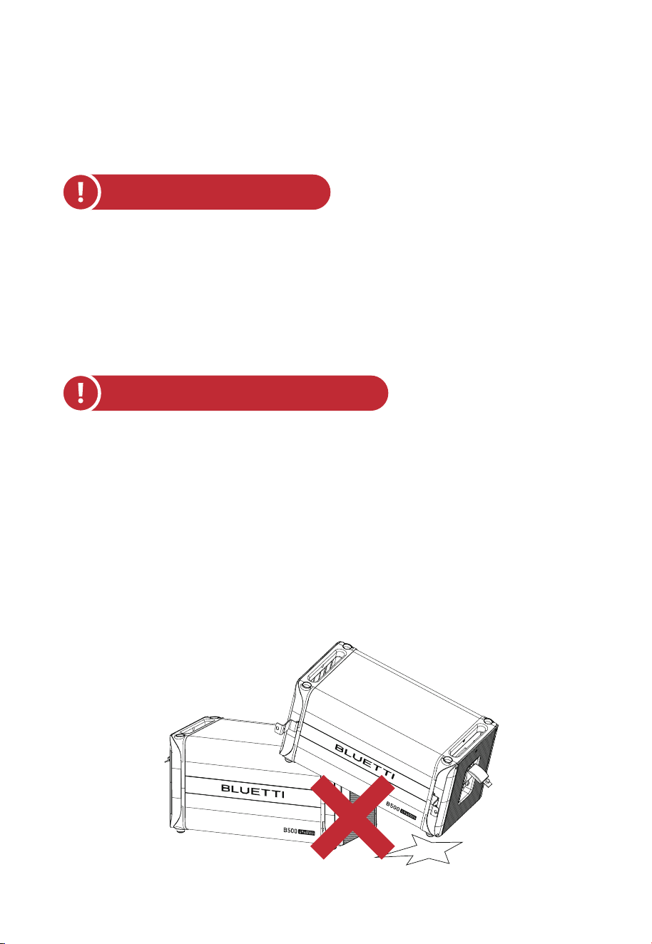
Fig. 1-1
Fire Emergency Measures:
Battery Drop Emergency Measures:
1.3.4 Other Requirements
•
In case of fire, power off the system if it is safe to do so.
• Use carbon dioxide, FM-200, or ABC dry powder fire extinguisher.
• Remind firefighters to avoid contact with components carrying dangerous voltage
to prevent the risk of electric shock.
• Overheating may cause the battery to deform and leak corrosive electrolytes or
toxic gas. Keep away from batteries to avoid skin irritation and chemical burns.
• If the battery pack is dropped, violently impacted or tilted during installation,
internal damage may occur. So do not use such battery packs to avoid safety risks
such as battery leakage and electric shock.
• If the dropped battery is not obviously deformed or damaged, and there is no
abnormal smell, smoke or fire, please contact a professional to transfer the battery
to an open and safe place, and contact BLUETTI support.
• If the battery is obviously damaged or there is an abnormal smell, smoke or fire,
please evacuate immediately, and contact a professional or BLUETTI support.
Professionals can use fire extinguishing facilities to extinguish the fire under safety
protection.
15
JUST POWER ON

1.3.5 Battery Disposal
•
Safely and carefully dispose˜of˜used batteries by the provisions of local laws and˜
regulations. Avoid treating batteries as regular household waste, as improper
disposal can lead to environmental pollution.
• If you find a leaking or damaged battery pack, contact us immediately or an
authorized battery recycling partner for expert assistance.
• If the battery pack reaches the end of its lifespan, please contact the battery
recycling company for further assistance.
• To maintain battery integrity, do not expose used batteries to high temperatures or
direct sunlight.
• Protect used batteries from moisture and corrosive substances to avoid potential
hazards.
1.4 Electrical Safety
1.4.1 General Requirements
•
Make sure that all electrical connections comply with your local electrical
standards.
• User-prepared cables should adhere to local laws and regulations.
• When performing electrical operations, use insulated tools for safety.
1.4.2 Grounding Requirements
•
Always make the ground connection first and disconnect it last when installing or
removing the equipment.
• Take care not to damage the grounding conductor.
• Before operating the equipment, always confirm that it is securely and reliably
grounded.
1.4.3 Wiring Requirements
•
Keep cables at least 1.18in (30mm) away from the heating devices or heat sources
to prevent damage caused by excessive heat.
• Group cables of the same type together to minimize electromagnetic interference.
Additionally, ensure that cables of different types should be laid at least 1.18in
(30mm) apart without intertwining and crossing.
16
JUST POWER ON

The equipment generates high voltage during operation, which
can cause electric shock leading to severe injury, property
damage, or even death. Please strictly follow the safety instruc-
tions provided in the user manual and adhere to relevant
electrical safety codes.
Warning
1.5 Maintenance Requirements
To ensure your safety while maintaining the system, please follow the following
steps:
Step1: Disconnect the power grid.
Step2: Disconnect the battery and solar systems.
Step3: Wait at least 30 minutes until the equipment is discharged.
• Follow the anti-static requirements to prevent electric shock and other potential
hazards.
• For any maintenance needs, please contact your local authorized service center.
• Place temporary warning signs or erect fences to prevent unauthorized access to
the maintenance site.
• To ensure personal safety and proper equipment usage, establish a reliable
grounding connection before use.
• Wear personal protective equipment (PPE) during operation. If there is a possibility
of personal injury or equipment damage, stop operation immediately, and take
appropriate protective measures.
• Cables used in the PV grid-connected power generation system must be firmly
connected, well insulated, and has proper specifications.
• Take necessary measures to protect cables when passing through pipes or holes.
• Safe Construction Practices:
(a) All cable installations should be carried out in environments above 0°C to
maintain cable flexibility and integrity. Handle the cable with care, especially
when working in low temperature environments.
(b) If the cable has been stored below 0°C, allow it to acclimate to room tempera-
ture for a minimum of 24 hours before installation.
17
JUST POWER ON

• Use tools correctly to avoid injury or damage to equipment.
• Do not touch energized equipment.
• Do not clean the electrical components inside and outside the cabinet with water.
• Do not stand, lean on or sit on top of the equipment.
• Do not damage the equipment modules.
• When the battery fails, avoid touching the battery and be careful of high tempera-
ture.
• Do not disassemble or damage the battery. The released electrolyte is harmful to
your skin and eyes. Avoid contact with electrolyte.
• Batteries can cause electric shock and high short-circuit current. When using
batteries, please note the following:
(a) Remove any metal objects, such as watches and rings, from yourself.
(b) Use tools with insulated handles.
(c) Wear rubber gloves and boots.
(d) Avoid the metal objects to short circuit battery terminals.
(e) Do not place tools or metal parts on top of the battery.
(f) Disconnect the charging power source before connecting or disconnecting
battery terminals.
1.6 Transportation Requirements
All components of the EP900 home energy storage system leave the factory in
optimum electrical and mechanical state. It's necessary to use original or appropri-
ate packaging to ensure the product safety during transportation. When you receive
the product, inspect for any kind of damage and note the damage on the delivery
receipt. The shipping company will be responsible for any damage or loss of the
product during transportation. If necessary, please contact us for further assistance.
1.7 Storage Requirements
•
When not using the EP900 for extended periods of time, power it off and remove
all electrical connections.
• Charge the system to 40%-60% SoC before storage.
• In order to keep the battery healthy, fully charge and discharge the system every 3
months.
18
JUST POWER ON

1.8 Handling Requirements
Weight
<18kg (39.7Ibs)
18kg-32kg (39.7lbs-70.5lbs)
32kg-55kg (70.5lbs-121.3lbs)
>55kg (121.3lbs)
Number of people
1
2
3
4 or a cart
Table 1-1 Recommended Number of People Based on the Weight of Product
• Make sure the place where to store the system is well ventilated and spacious.
• Do not store the system in flammable or explosive environments.
• It is recommended to clean the surface frequently with a dry soft cloth.
• Keep the system out of the reach of children and pets.
• Do not stack anything on top of the equipment during storage.
• Avoid exposing the equipment to rain, humidity or direct sunlight.
• For details of storage temperature, please refer to Chapter 11. Specifications.
19
JUST POWER ON
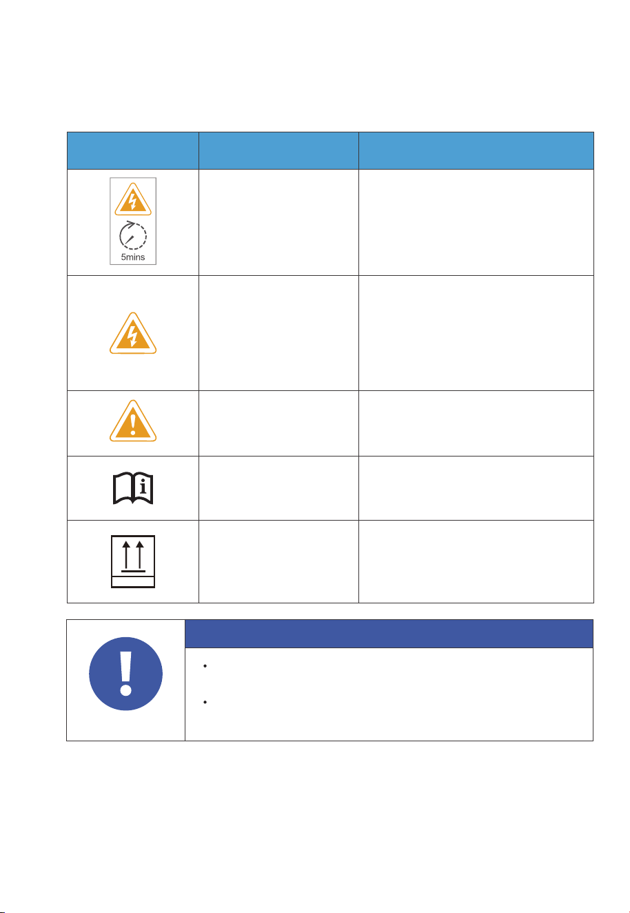
1.9 Label Description
Label Name Description
Discharge delay
Electrical shock
warning
There is still residual voltage after the
equipment is powered off. Please wait
at least 5 minutes until the equipment
is discharged.
The system generates high voltage
during operation.
The installation, commissioning, and
maintenance should only be
performed by qualified professionals
or trained personnel.
Warning
Be careful. Hazards may occur
during operation.
Read instruction
Please read the instruction
carefully before operating the
energy storage system.
This side up
It must be transported, handled and
stored in the correct orientation. The
arrow always faces upwards.
This Side Up
Table 1-2 Labels and Description
Attention
The symbols on the box contain important information for safe
operation.
The nameplate on the side of the box contains important parameter
information related to the product.
20
JUST POWER ON
2. EP900 Home Energy Storage System
2.1 Introduction
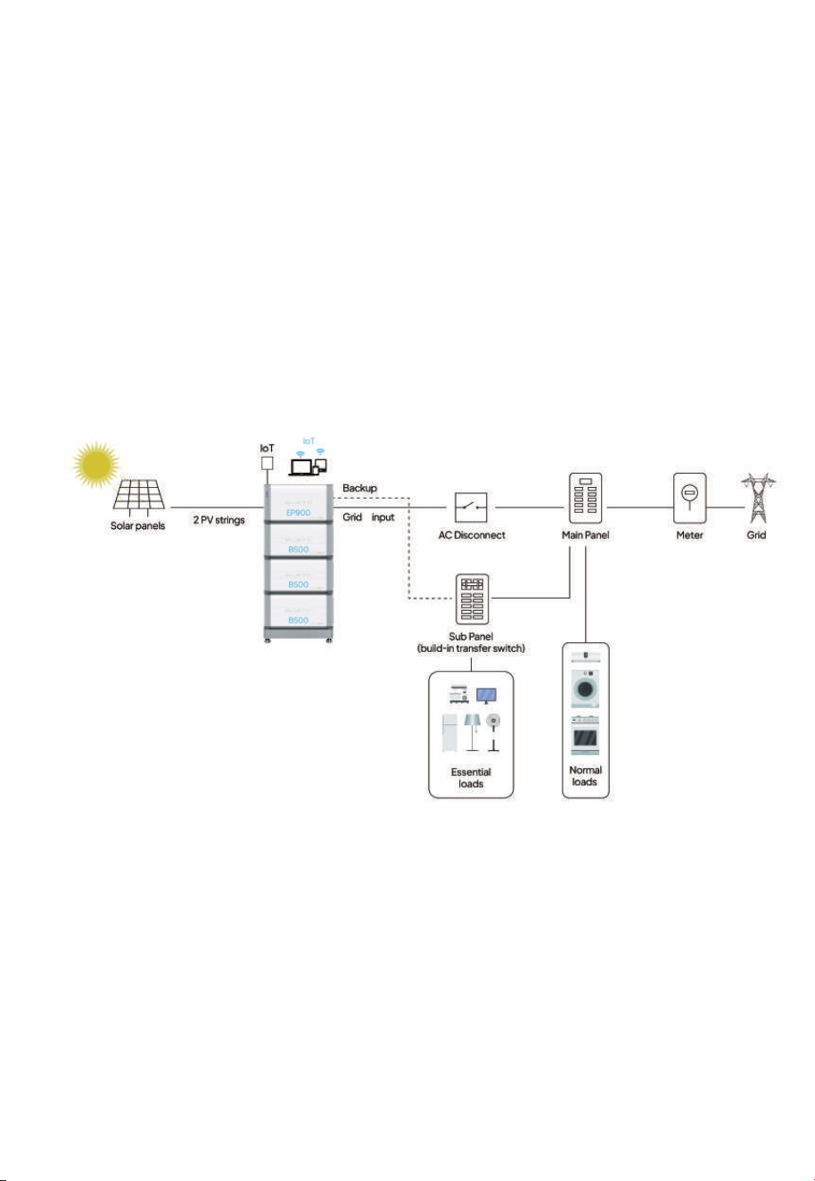
The EP900 energy storage system consists of a grid-tied inverter (EP900), battery
packs (B500), an IoT controller, and other accessories (current transformers, rapid
shutdown, safety switches, cables, etc.). It seamlessly integrates with solar panels
and home main panels to provide a complete home energy storage and grid-con-
nected solar power solution.
With smart power generation and uninterruptible power supply features, the
system is suitable for homes and regions with energy shortages or unstable power
supply. Monitor and control it with a dedicated app - experience easy and practical
power management.
21
JUST POWER ON

Fig. 2-1 EP900 Home ESS Diagram
Instruction
The introduction describes the general behavior of EP900 energy
storage system. The system operating mode can be adjusted on
the BLUETTI APP.
Item Description Note
EP900 Inverter
An energy storage photovoltaic
grid-connected inverter to handle
photovoltaic input, grid-connected
charging, and discharging.
Please refer to Chapter 3.
EP900 Home Energy
Storage Inverter for details.
B500 Battery
LiFePO4 battery pack to power the
EP900 system.
Please refer to Chapter 4.
B500 Battery for details.
IoT Controller
A component to monitor EP900
Home ESS operations.
Please refer to Chapter 5.
IoT Controller for details.
Grid Communication
Module
A component for utility companies to
collect real-time data from inverters
and regulate the power grid via WiFi. It
facilitates efficient energy intercon-
nection and maximizes benefits f rom
energy subsidy policies.
Connects to utility company
servers that comply with the
IEEE 2030.5 protocol,
offering plug-and-play,
remote scheduling, and
data monitoring features.
BLUETTI app
An application for seamless communi-
cation with the EP900 inverter,
supporting both near-end (Bluetooth)
or remote (WiFi) connectivity.
Please refer to EP900
Energy Storage System App
User Manual for details.
CT (Current
Transformers)
Components to contribute to
intelligent operation management
within the EP900 system.
Rapid Shutdown
A component to disconnect the DC
input from the solar system.
/
/
/
Safety Switch
A component to protect grid-connect-
ed circuits.
22
JUST POWER ON

2.2 Working Mode
The EP900 offers four operating modes to accommodate various energy plans. You
can choose the one that best suits your home power supply configuration.
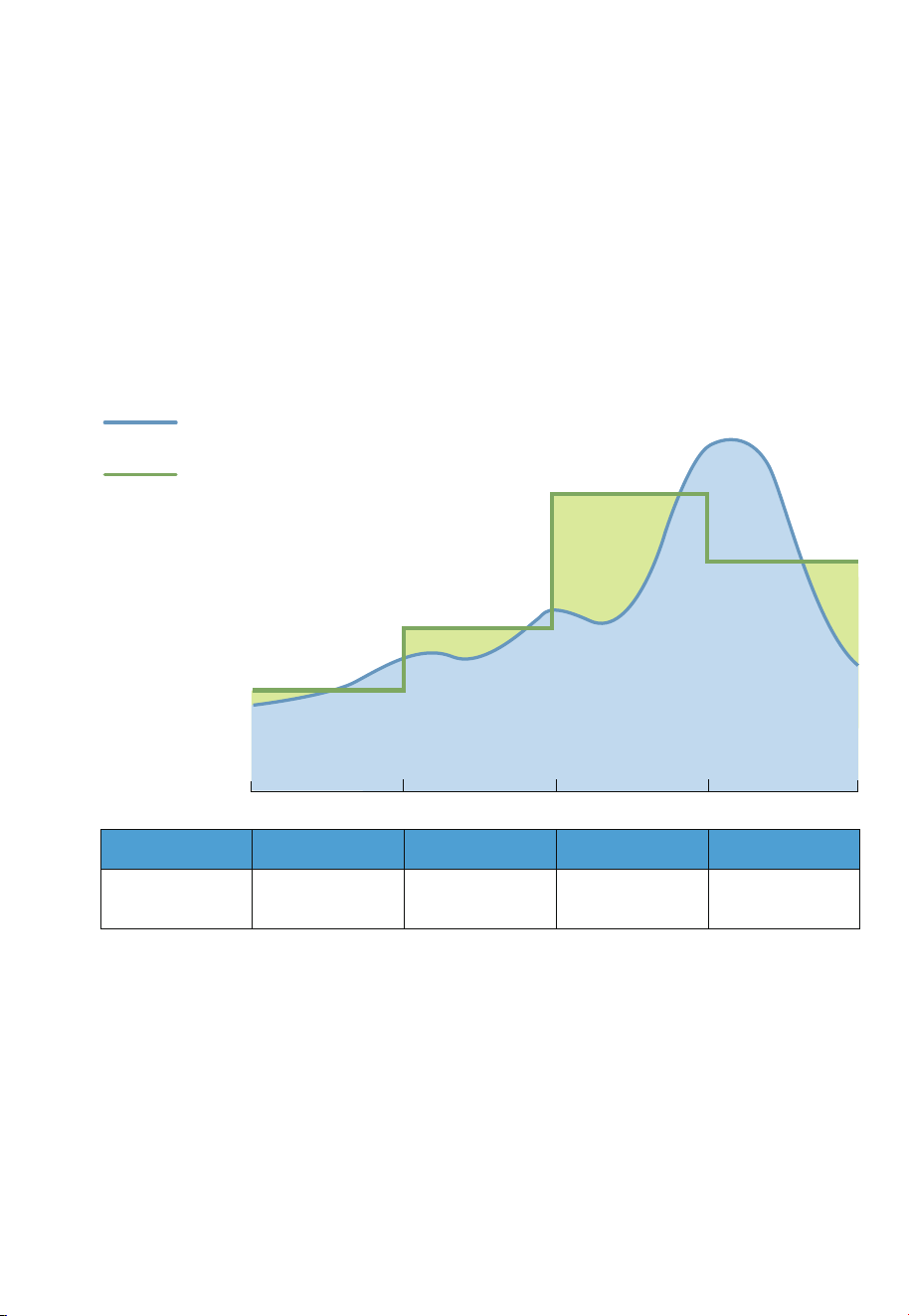
• Backup
In this mode, the EP900 acts as a reliable home backup power source that only
kicks in when the grid fails. It prioritizes charging its batteries from solar energy over
the grid, making it an eco-friendly and sustainable choice for your home energy
needs. With ample energy reserves, it provides a seamless power supply, perfect for
areas with unreliable grids.
Input power
from grid
Backup
output power
0
(W)
Time
0
(W)
Time
Fig. 2-2
23
JUST POWER ON
• Time of Use
In this mode, you can customize the charge and discharge periods as well as
charging power according to your specific requirements. During the charge period,
the EP900 will draw power from the grid, usually making use of off-peak tariff time
windows (TOU) when electricity rates are lower, to replenish its energy storage.
Moreover, you can set the battery State of Charge (SoC) limits to regulate the
amount of power that the EP900 draws from the grid, while reserving the remain-
ing capacity in the battery for solar energy supplement.
0:00
Electricity Price
6:00 12:00 18:00 24:00
Home Consumption
Period Charging Discharging Discharging Discharging
Power Source
for Loads
Grid
EP900 / EP900
+ Solar
EP900 / EP900
+ Solar
EP900
Fig. 2-3
24
JUST POWER ON

• Self-consumption
In this mode, the EP900 prioritizes the direct consumption of solar energy to meet
immediate household energy needs. Any surplus solar energy generated during the
day is intelligently stored in the battery for usage during peak hours or in the event
of a power outage. With such a strategy, the EP900 ensures an efficient and reliable
power supply, reducing reliance on the grid and promoting energy independence.
Fig. 2-4
EP900
Operation Status
Discharging
Midnight
Time
Morning Noon Afternoon Evening
DischargingDischarging Charging Discharging
Power Source
for Loads
EP900 EP900+Solar Solar EP900+Solar EP900
PV Generation
Used for
/ Loads Loads and Batteries Loads /
EP900
EP900
ESS+Solar
Direct consumption
>Storage
Household
runs on solar
Household
runs on
EP900+Solar
EP900 ESS+
Utility grid
PV generation
Household consumption
25
JUST POWER ON

• Custom
In this mode, you can customize all of the above mode settings to your preference.
Fig. 2-5
PV generation
Household consumption
EP900
Operation Status
Charging
2:00
Time
6:00 12:00 18:00 22:00
DischargingDischarging Discharging Discharging
Period
Charging DischargingDischarging Standby Standby
PV Generation
Used for
/ Batteries Loads and Batteries Batteries /
Power Source
for Loads
/ Grid EP900+Solar EP900+Solar EP900
Household
runs on EP900
EP900
ESS+ Solar
Direct consumption
> Storage
Household
runs on solar
Household
runs on
EP900+Solar
Household
runs on EP900
26
JUST POWER ON
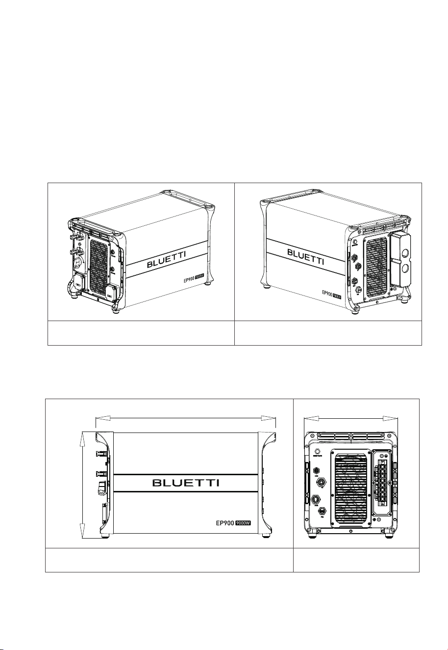
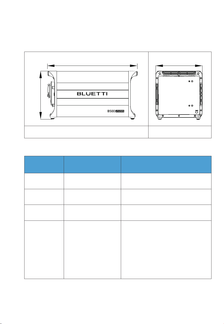
14.567in(370mm
25.039in(636mm)
12.795in(325mm)
3. EP900 Home Energy Storage Inverter
EP900 inverter is an˜energy storage photovoltaic grid-connected inverter that can
handle photovoltaic input, grid-connected charging, and discharging. It is an
important part of the home energy storage system.
Table 3-1
Left Right
Dimensions
Table 3-2 (Unit: in/mm)
Front Right
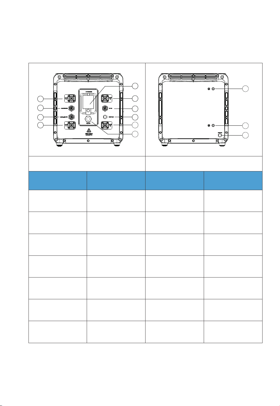
3.1 EP900 Inverter Overview
Appearance
27
JUST POWER ON
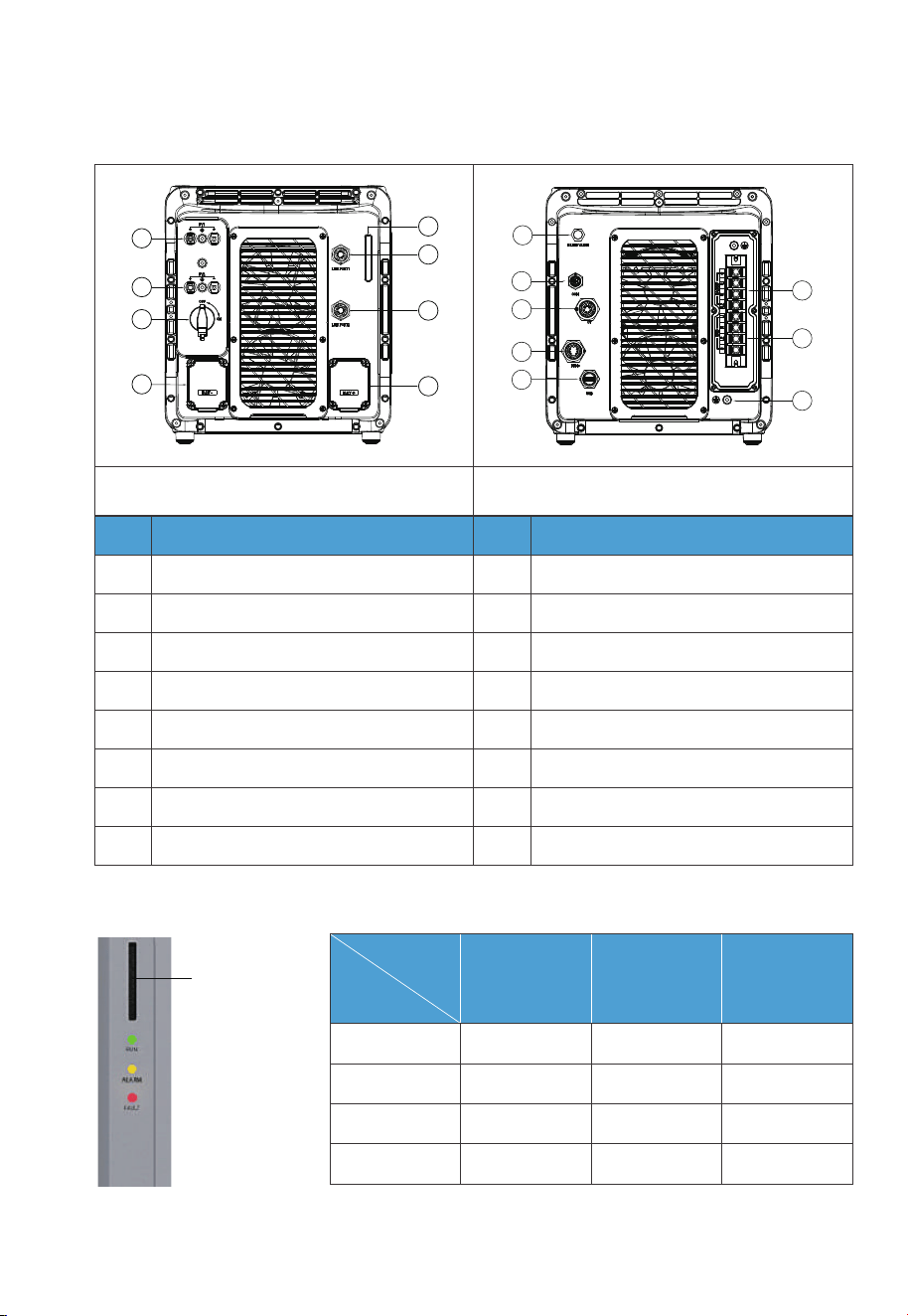
3.2 LED Indicator
Fig. 3-1 Table 3-4
Indicator
Interface
Table 3-3
Left
No.
1
2
3
4
5
6
7
8
PV1 Input(Max. 3000W)
PV2 Input (Max.6000W)
DC Switch
BAT- Terminal
LED Indicator
LINK PORT 1
LINK PORT 2
BAT+ Terminal
BLEED VALVE
COM Port (Grid Communication Module)
CT Port
DRMs Port (Generator + Meter)
USB Port
BACKUP Terminal
GRID Terminal
GND Terminal (Grounding)
9
10
11
12
13
14
15
16
No.Name Name
Right
9
10
11
12
13
14
16
15
1
2
3
4
5
6
7
8
System
Status
Run ON OFF OFF
ON ON OFF
OFF OFF ON
OFF ON ON
Run +Alarm
Fault
Alarm and fault
Green Yellow Red
LED
28
JUST POWER ON

Table 3-5 Fault Code
3.3 Buzzer Alarm
When a fault occurs, the buzzer emits a series of 10 beeps. Each time lasts for 5
seconds with a 1-second interval between each beep.
Note: The buzzer alarm can be turned off in the BLUETTI app.
3.4 Maintenance and Care
EP900 inverter requires regular maintenance:
• Inspect and clean the fan, fan guard, and heat sink if dust or blockages are present.
• Ensure that the fan operates without any abnormal noise.
• Check and tighten AC and DC cable connections annually using a torque wrench.
Description
Hardware BUS Overvoltage
Hardware BUS2 Overvoltage
Hardware Battery Overvoltage
Hardware Inverter Overcurrent
Hardware Inverter 2 Overcurrent
Hardware LLC1 Input Overcurrent
Hardware LLC2 Input Overcurrent
Hardware PV1 Failure
Hardware PV2 Failure
Hardware Input Overcurrent
Fault Code
B005
B006
B007
B008
B009
B010
B011
B026
B027
B034
29
JUST POWER ON
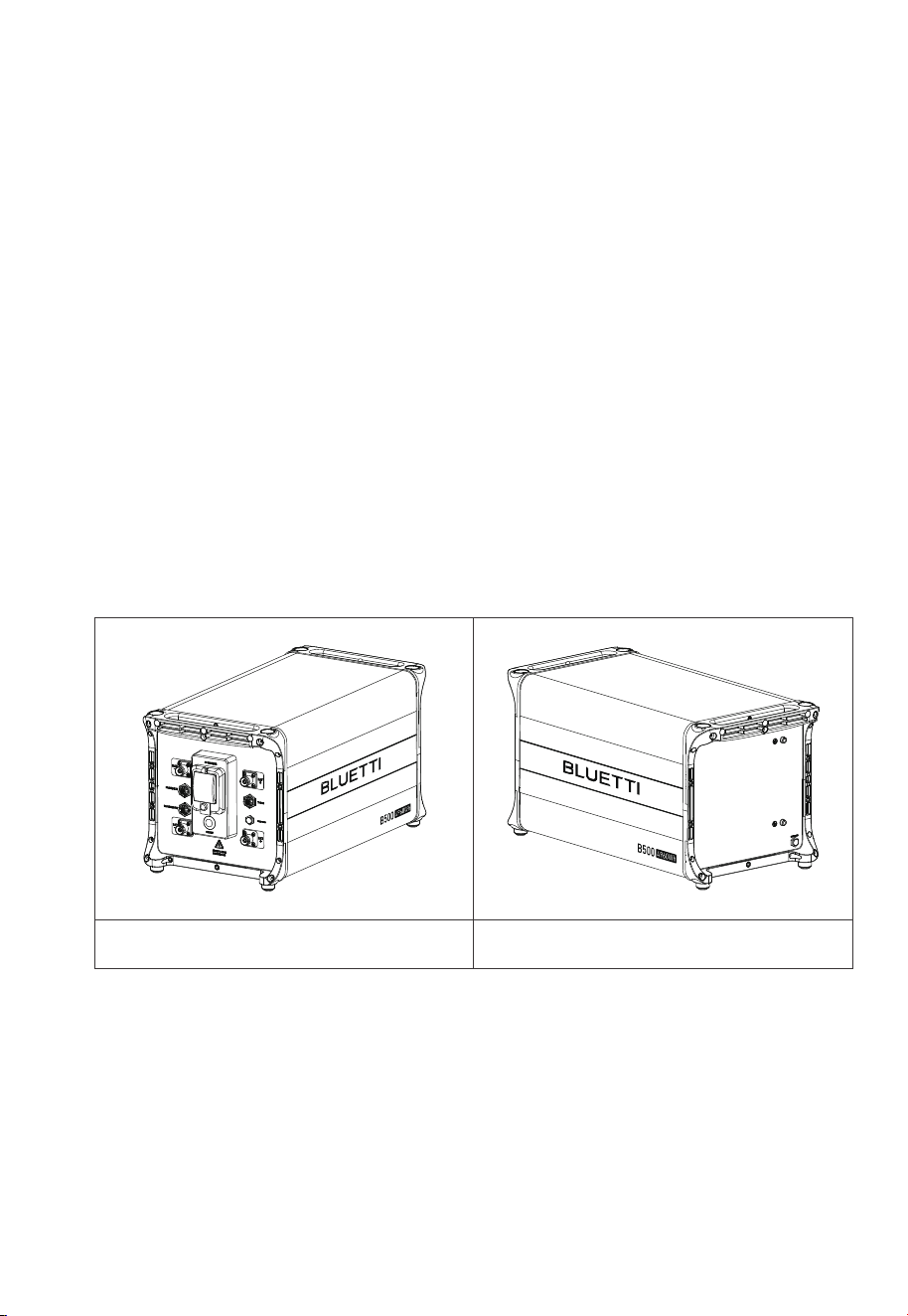
4. B500 Battery
4.1 Introduction
The B500 battery energy storage system is designed for residential and light
commercial use. Single B500 battery pack has a capacity of 4.96kWh. The EP900
supports 4 *B500 units for a whopping 19.84kWh, enough to power a house for
several days.
The B500 comes with a reliable battery management system (BMS) with a
multi-stage architecture that provides real-time detection of the battery pack's
voltage, current and temperature, protecting the system from overvoltage, under-
voltage, overcurrent, overtemperature and undertemperature. At the same time,
the redundancy design provides unprecedented safety and stability for the B500
battery energy storage system.
4.2 Overview
Appearance
Table 4-1
Left Right
30
JUST POWER ON
Interface
Table 4-2
Left
No.
1
2
3
4
5
6
7
8
9
10
11
12
13
BAT- Terminal 1
PACK LINK IN
PACK LINK OUT
BAT- Terminal 2
Main Switch
BAT+ Terminal 1
Bleed Valve 1
BAT+ Terminal 2
Power Button
Grounding Port 1
Grounding Port 2
Bleed Valve 2
Inverter Signal Port
(TO PCS)
No.Name Name
Right
1
2
3
4
5
6
7
8
9
10
11
12
13
31
JUST POWER ON
4.3 LED Indicators
Dimensions
Light
OFF B500 is not started. Can operate the circuit breaker.
Can not operate the circuit breaker.
Can not operate the circuit breaker.
B500 is running.
B500 is shutting down.
B500 is not running.
ON
Flash at 0.5Hz
Flash at 1Hz
Description Note
Table 4-3 (Unit: in/mm)
Front Right
If all indicators are flashing, the battery
module is temporarily unavailable and is
restoring, please wait patiently.
If it lasts for more than 1 hour, please
contact BLUETTI support or your local
BLUETTI dealers.
If a single indicator flashes, the B500 is in
a fault condition. Please contact
BLUETTI support or your local BLUETTI
dealers.
12.795in(325mm)
13.307in(338mm)
25.039in(636mm)
32
JUST POWER ON

4.4 Maintenance and Care
•
If indicator lights are off on parallel-connected battery packs, please contact
BLUETTI support or your local BLUETTI dealers.
• If there's an issue with the B500, please contact BLUETTI support or your local
BLUETTI dealers.
• If the B500 is temporarily unavailable and is recovering, please wait patiently. If it
lasts over 1 hour, please contact BLUETTI support or your local BLUETTI dealers.
• Do not operate the unit if the circuit breaker switches to “OFF” automatically
due to a system malfunction. Please contact BLUETTI support or your local
BLUETTI dealers for assistance.
• To avoid abnormal operation, do not disconnect the circuit breaker while the
B500 is in normal operation.
• Do not disassemble the metal enclosure of the B500 to prevent electric shock
and explosion.
• If any battery’s SoC drops to 1% without power input, turn off all battery main
switches to prevent overdischarge. Restart the system when charging from the
grid.
Note: SoC won’t drop to 1% when connected to the grid.
• Charge the unit immediately when the SoC drops to 5% and keep it at least at
5% for continuous operation.
• Before storing the unit, charge it to 40% to 60% SoC and cycle it fully at least
every 3 months to maintain battery health.
33
JUST POWER ON
5.1 Communication Principle
The IoT controller supports WiFi and Bluetooth communication, allowing users to
monitor the EP900’s operating status via the app. Everything about the system,
including power generation and consumption, and alarms, can be uploaded to the
BLUETTI server via the WiFi network. By registering the EP900 with your BLUETTI
account, you’re able to monitor and control this unparalleled power plant anytime
and anywhere.
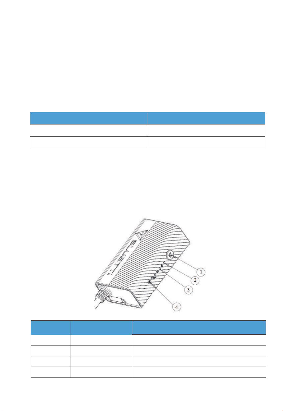
5.2 Overview
The IoT controller supports WiFi and Bluetooth communication, allowing users to
monitor the EP900’s operating status via the app. Everything about the system,
including power generation and consumption, and alarms, can be uploaded to the
BLUETTI server via the WiFi network. By registering the EP900 with your BLUETTI
account, you’re able to monitor and control this unparalleled power plant anytime
and anywhere.
5.IoT Controller
Note
Standard
Standard
Communication
WiFi
Bluetooth
No.
Menu Button
WiFi Indicator
Bluetooth Indicator
Reboot Button
1
2
3
4
/
Flash till the controller connected to WiFi.
Flash till the controller connected to Bluetooth.
/
Name
Description
34
JUST POWER ON
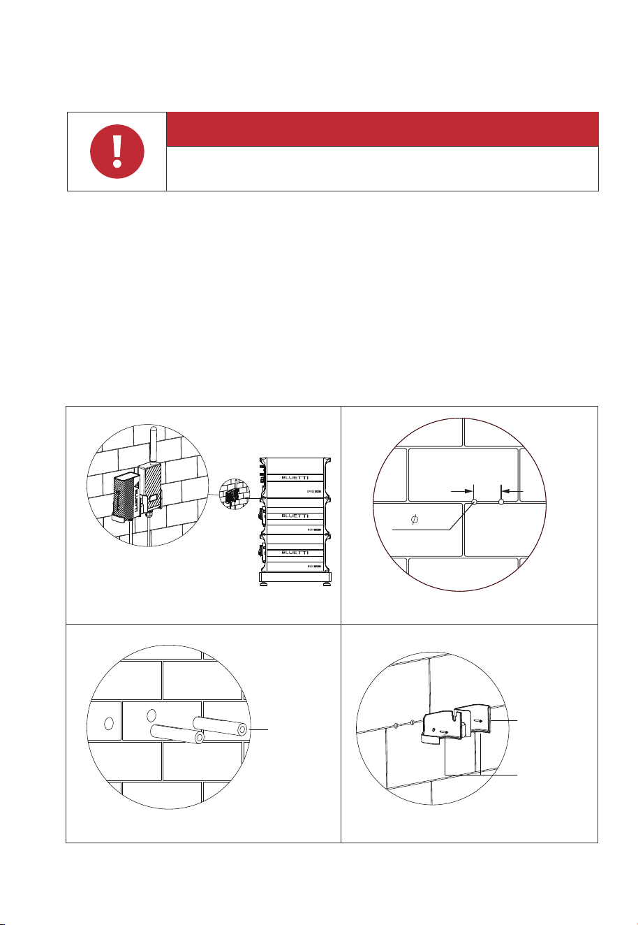
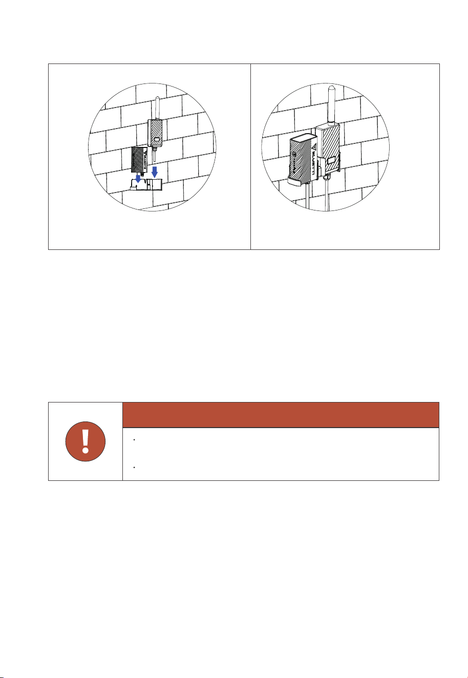
5.3 Installation
Step 1: Drill 2 pilot holes in the wall with an electric drill (0.197in / 5mm). Please refer
to the drill position and hole size shown in Fig. 5-2-1 and Fig. 5-2-2. The depth
of hole is 1.02in (26mm).
Step 2: Hammer the expansion wall plug in until it’s flush with the wall. See Fig.5-2-3.
Step 3: Fix the mounting bracket onto the wall and use the cross screwdriver to
fasten 2 self-tapping screws into the wall plugs. See Fig. 5-2-4.
Step 4: Align the controllers’ buckles over the U-slot and push the controllers
downwards until they snap in place. See Fig. 5-2-5 and Fig. 5-2-6.
Fig. 5-2-1 Fig. 5-2-2
Fig. 5-2-3 Fig. 5-2-4
Expansion
Wall Plug
IOT/WiFi
Bracket
Self-tapping
Screw
(2.84in)
72mm
2- 5.0
Danger
Make sure to check for any cables or pipes before drilling into the wall.
35
JUST POWER ON
5.4 Safety Instructions
•
The IoT controller is ONLY applicable to BLUETTI products.
• Do not keep the controller near heat sources or in high temperatures.
• Do not store the controller with flammable liquids, gases, or explosive materials.
• The inspection, testing, and maintenance should be performed by qualified
personnel.
IOT/WiFi
Controller
Fig. 5-2
Fig. 5-2-5 Fig. 5-6
Warning
Do not block or cover the openings of the controller. Keep it out of the
reach of children.
Use dry powder fire extinguisher in case of fire.
36
JUST POWER ON
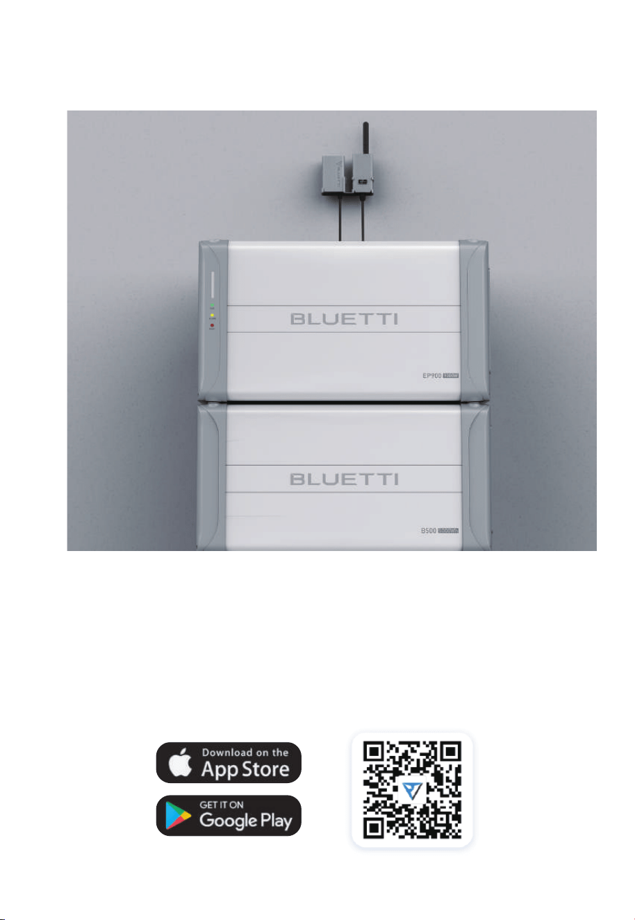
Fig. 5-3
5.5 Connection and Operations
Step 1: Plug the IoT cable into EP900 LINK PORT 1.
Step 2: Turn on EP900, and the IoT controller starts up automatically.
Step 3: Open the app to operate.
To register and log in, simply follow the steps below:
• Scan the QR code below to download the BLUETTI app, or search for “BLUETTI” in
the App Store / Google Play.
37
JUST POWER ON
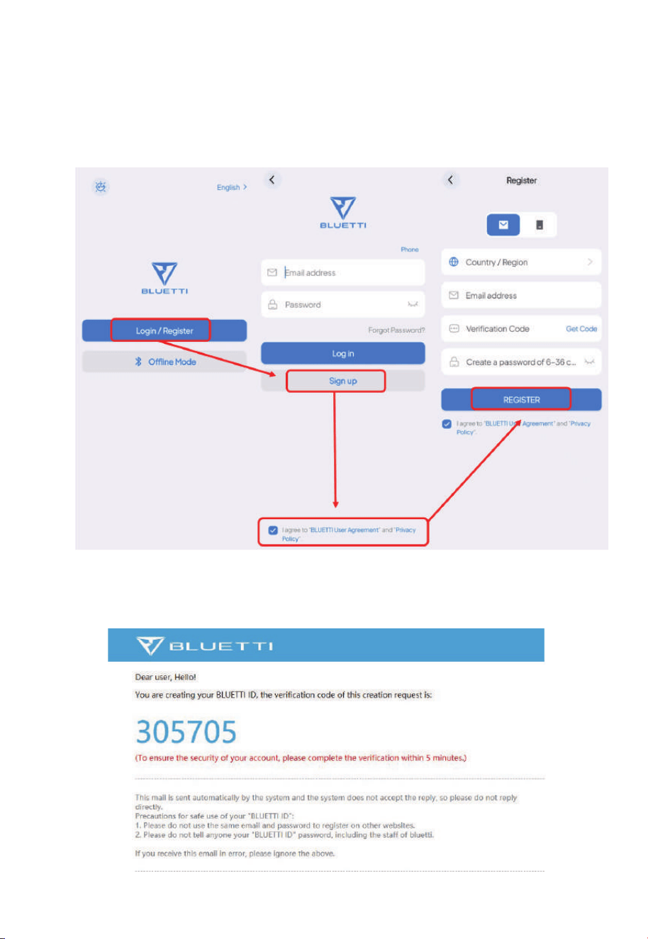
Fig. 5-4
Fig. 5-5
• The BLUETTI app connects to EP900 via Bluetooth or WiFi. Tap “Login / Register”
and “Sign up” to register your BLUETTI account. Fill in the necessary information to
continue.
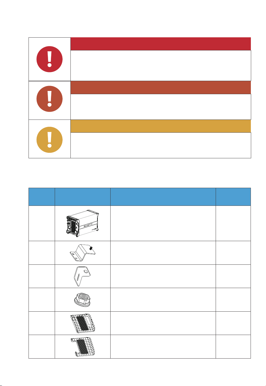
• Check your email for verification code from BLUETTI server, and fill in the code to
activate your BLUETTI account.
38
JUST POWER ON
6. System Installation
6.1 EP900 Inverter Packing List
Table 6-1
Attention
Instruction
Warning
Danger
Caution
Disconnect all electrical connections from the product.
Do not install the equipment below pipes, windows, or areas
prone to water leaks and accumulation.
Do not block ventilation openings or heat dissipation pathways
while operating to prevent overheating and fire risks.
Handle the equipment and accessories with care during
loading, unloading, and transportation.
1 1
2 2
2
2
3
4
EP900 Inverter
Bracket #1
Bracket #2
M5 hex nut
No. DescriptionPicture Qty.
1
1
5
6
Plastic cover (PV)
Plastic cover (AC, with label)
39
JUST POWER ON
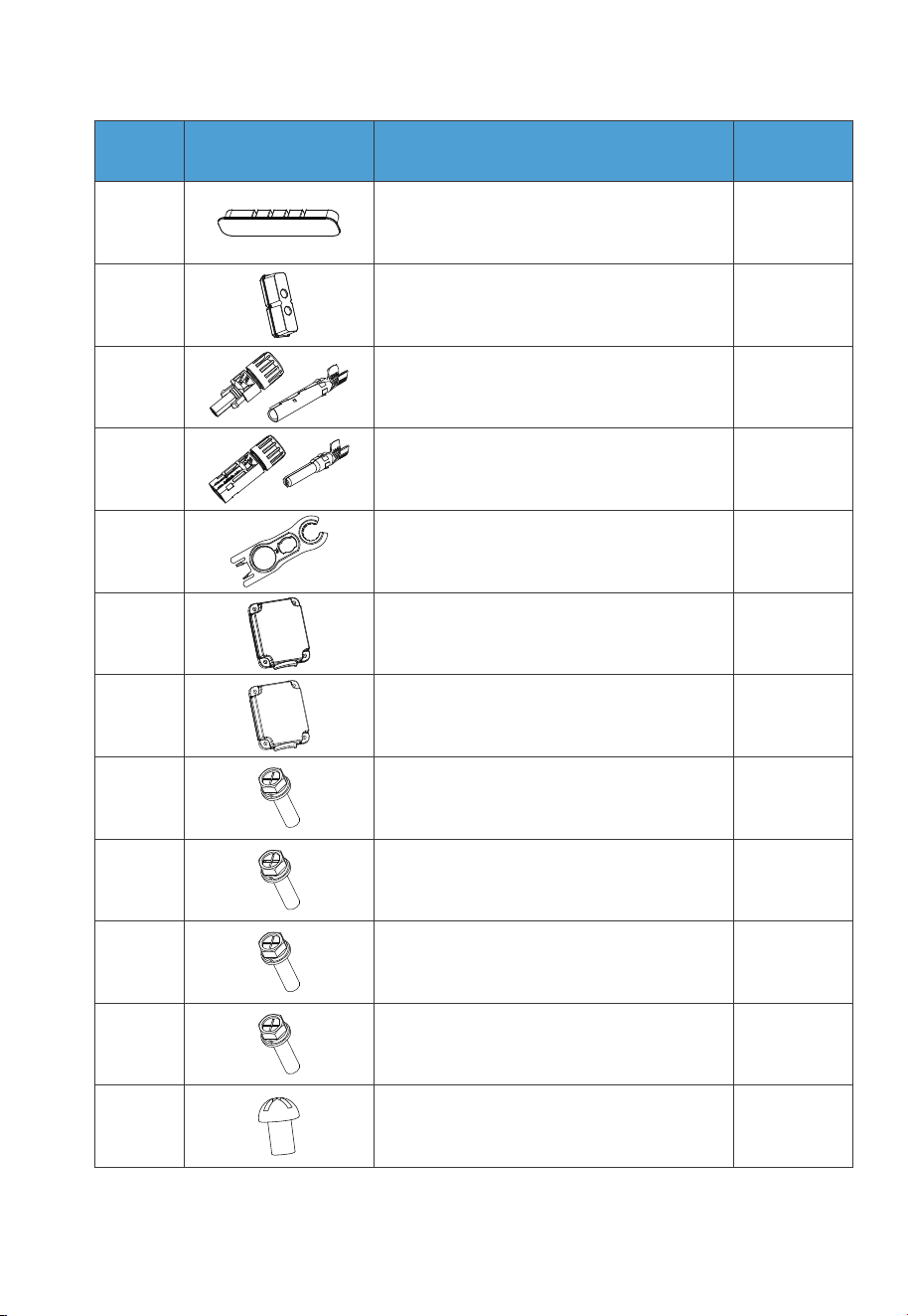
6
2
10
16
17
18
M6*12 screw
(For bracket)
M5*10 screw
(4 for fixing device to the bracket,
2 for PV grounding)
M4*10 screw
(For exterior trim)
1
2
2
2
7
8
9
10
Cord organizer
AC cable protection case
Plastic housing (PV+ Input)
Metal core (PV+ Input)
Plastic housing (PV- Input)
Metal core (PV- Input)
11
12
13
1
1
2
1414
Black protection cover (BAT- Input)
MC4 wrench
Red protection cover (BAT+ Input)
M4*12 screw (8 for BAT+/- protection cover,
6 for AC cable protection case)
215
M8*12 screw
(For battery power cable)
No. DescriptionPicture Qty.
40
JUST POWER ON
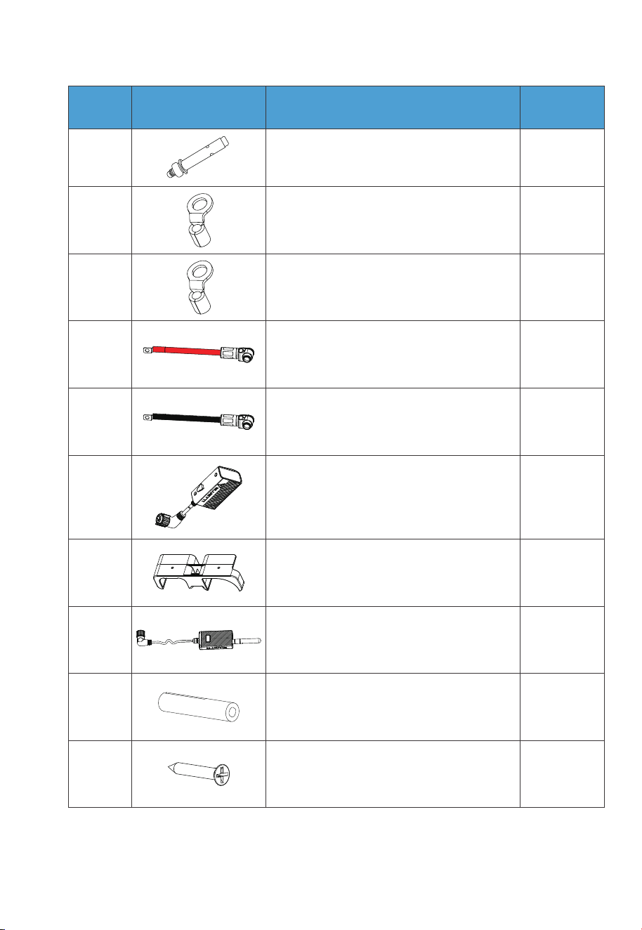
219
M8*60 expansion bolt
No. DescriptionPicture Qty.
9
3
20
21
RNB8-6 OT terminal (AC)
RNB3.5-5S OT terminal (PV Grounding)
22
23
24
1
1
1
1
1
25
26
Black battery power cable (Negative)
Red battery power cable (Positive)
IoT Controller
Mounting bracket
(grid / IoT controller)
Grid communication module
27 2
28
Expansion wall plug
2
M3 tapping screw (KA3*25)
41
JUST POWER ON
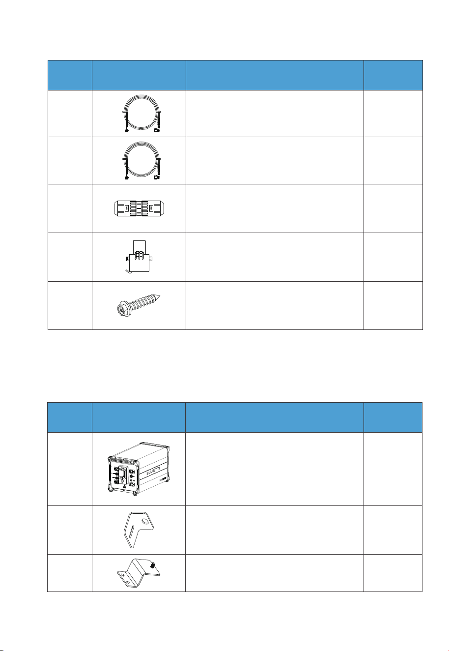
6.2 B500 Battery Packing List
Table 6-2
No. DescriptionPicture Qty.
29 1
130
CT communication cable (4m / 13ft)
DRMs + COM communication cable (4m / 13ft)
2
2
31
32
M20-6 PIN adapter
CT
233
Self-tapping screw, ST8×40
(for brackets)
1
2 2
1
23
B500 Battery Module
Bracket #1
Bracket #2
No. DescriptionPicture Qty.
42
JUST POWER ON
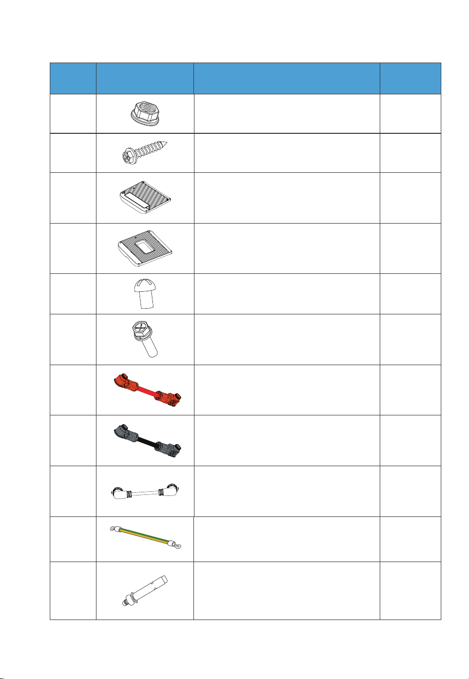
No. DescriptionPicture Qty.
24 M5 hex nut
25
Self-tapping screw, ST8×40
(for brackets)
1
1
4
10
1
6
7
8
9
10
Left cover
Right cover
M4*8 screw (for fastening covers)
M5*10 screw (for brackets)
Red battery expansion cable
(Positive)
111
Black battery expansion cable
(Negative)
12 1Communication cable
1
2
13
14
Grounding cable
M8*60 expansion bolt (for brackets)
43
JUST POWER ON
No. DescriptionPicture Qty.
2
1
15
16
M6*12 screw (Grounding cable)
Spare screw kit
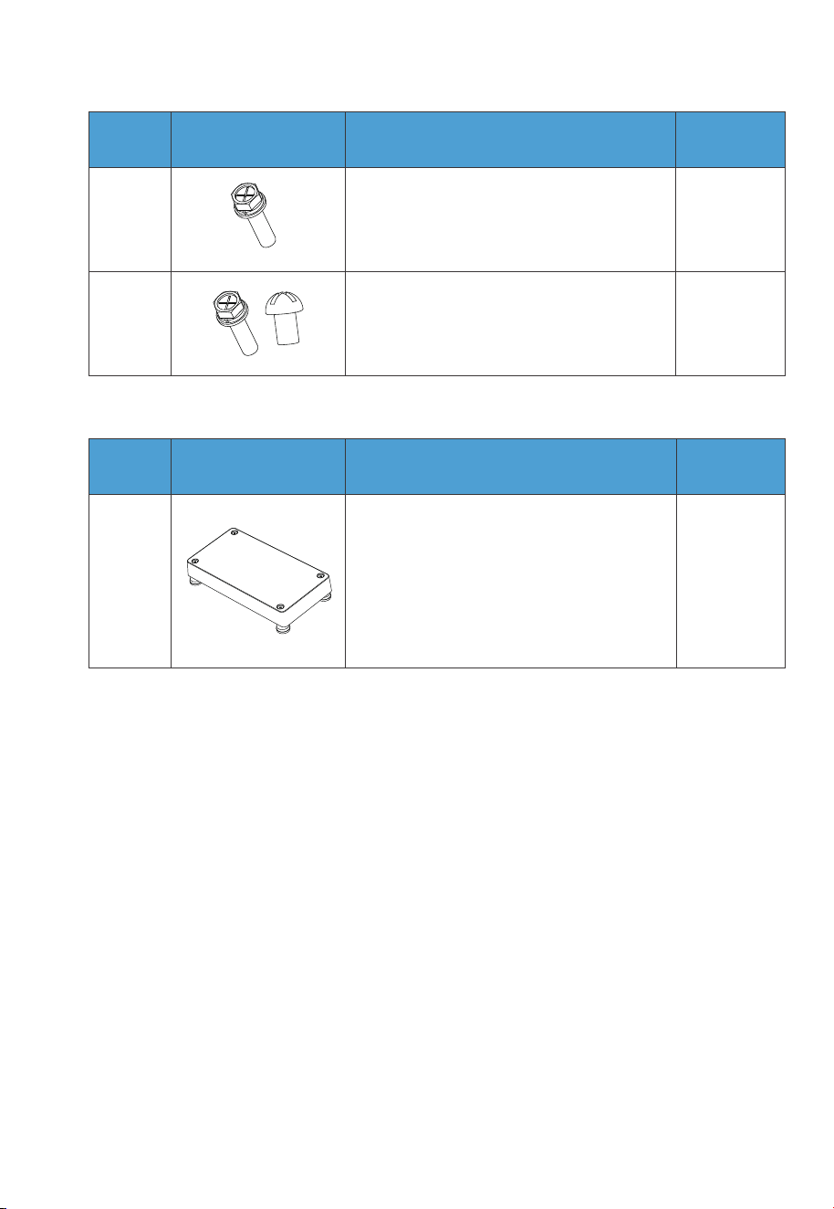
6.3 Base Packing List
6.4 Installation Requirements
6.4.1 Environment Requirements
•
Install the EP900 in a well-ventilated and spacious area to ensure good heat
dissipation.
• The EP900 inverter and the B500 battery both have a NEMA 4X rating and can be
installed indoors and outdoors. Please note that if you place the system outside the
house, use a shelter to protect it from direct sunlight, as this may cause a degrada-
tion in system performance.
• The enclosure and heat sink are very hot while the inverter is working, therefore do
NOT install the inverter in places where you might touch inadvertently.
• Keep the EP900 away from flammable liquids, gases, or explosive materials.
• Keep away from children and pets.
1
1
Base
No. DescriptionPicture Qty.
44
JUST POWER ON
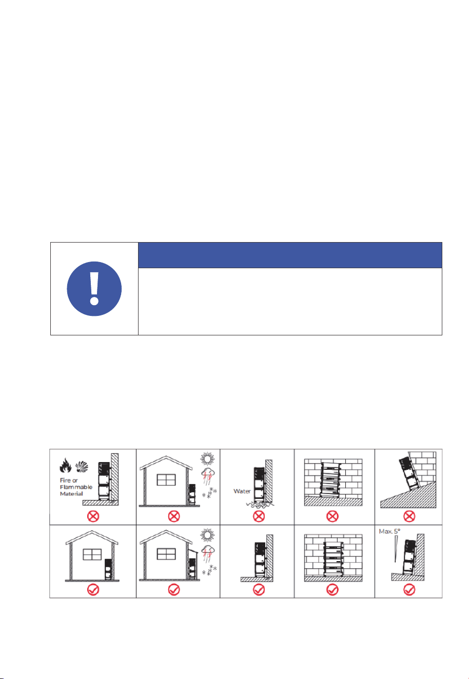
• Do not install the EP900 outdoors in salt-affected areas, as the accumulation of salt
may corrode the system. Salt-affected areas are those within 1640.42ft (500m) from
the coast or susceptible to sea breezes. Salt accumulation is influenced by seawa-
ter, sea breeze, precipitation, air humidity, topography and forest cover of adjacent
sea areas.
• Do not install the system in low-lying areas where water tends to accumulate.
Otherwise, water may leak into the equipment and result in system failure.
• Ambient temperature range: -4°F to 104°F / -20°C to 40°C.
• Relative humidity: 5%-95% (non-condensing).
• Maximum height: 6561.68ft / 2000m.
6.4.2 Location Requirements
•
The EP900 should be installed on˜a firm, flat, level base.
• Do not install the system on flammable materials.
• Consider the weight and placement of components to ensure adequate structural
support.
Attention
If the battery pack is dropped, violently impacted or tilted during
installation, it may result in internal damage. So do not use such battery
packs to avoid safety risks such as battery leakage and electric shock.
Fig. 6-1
45
JUST POWER ON
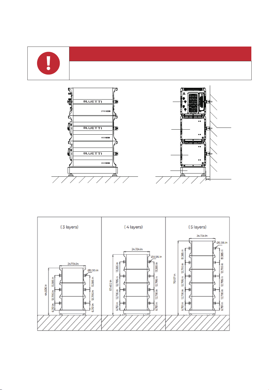
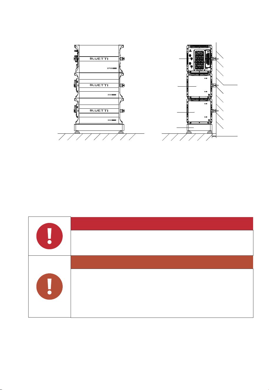
6.4.3 Space Requirement
Hole Positions
Note:
Stack up to 5 layers of equipment on the base, including the EP900 inverter.
Adjust one set of installation holes for each addition or removal of a battery pack.
Danger
Make sure to check for any cables or pipes before drilling into the wall.
Fig. 6-2
Fig. 6-3
Ground
Wall
B500
Base
B500
EP900
2.15 in/55mm
46
JUST POWER ON
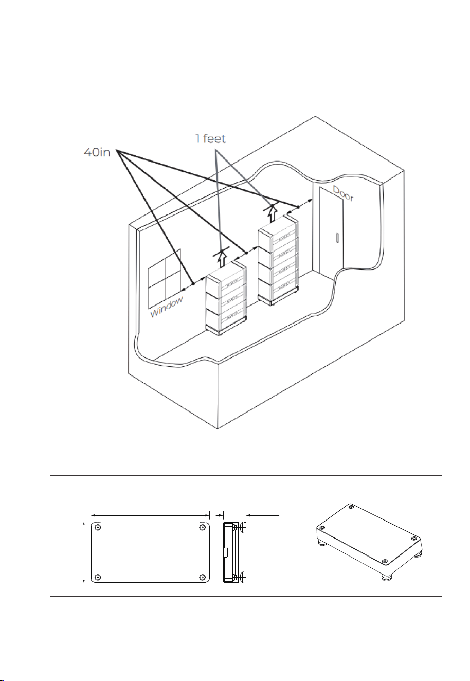
6.4.4 Base Dimensions
Layout Position
Note:
The EP900 Home ESS installation requires a minimum space of 23.15m3, as
shown in the specific space reference below.
Dimensions
Fig. 6-5
3D
25.04in
(636mm)
4.685in
(119mm)
12.6in
(320mm)
Fig. 6-4
47
JUST POWER ON
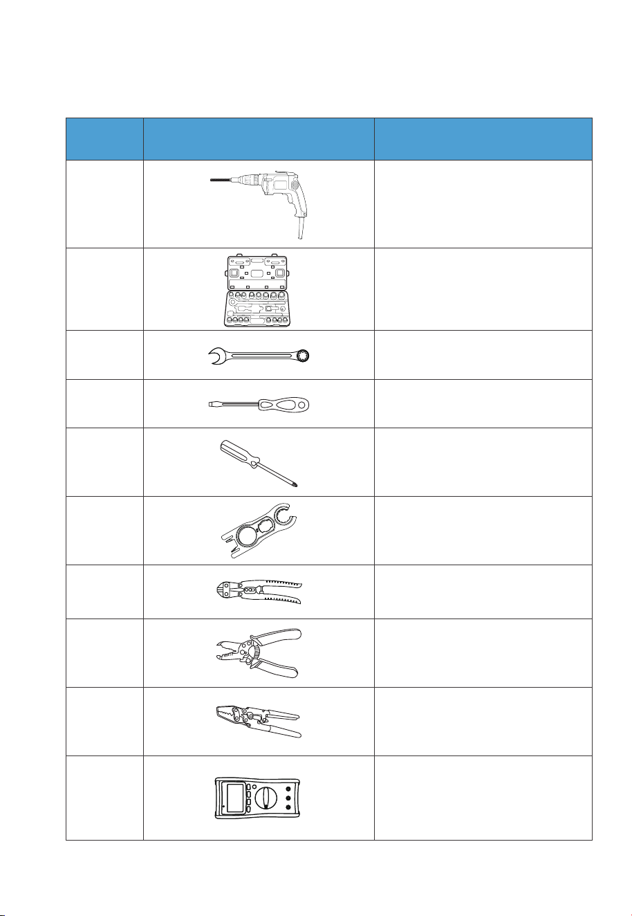
Table 6-4
6.5 Prepare the Necessary Tools
1
2
3
4
5
6
7
8
9
10
Electric drill
(0.197/0.315/0.394(in))
Socket wrench set
Wrench
Flat screwdriver
Cross screwdriver
(0.157in/4mm)
MC4 spanner
Cable cutter
Cable stripper
Cable Crimper
Multimeter
(DC voltage ˝
1000VDC)
No. DescriptionPicture
48
JUST POWER ON
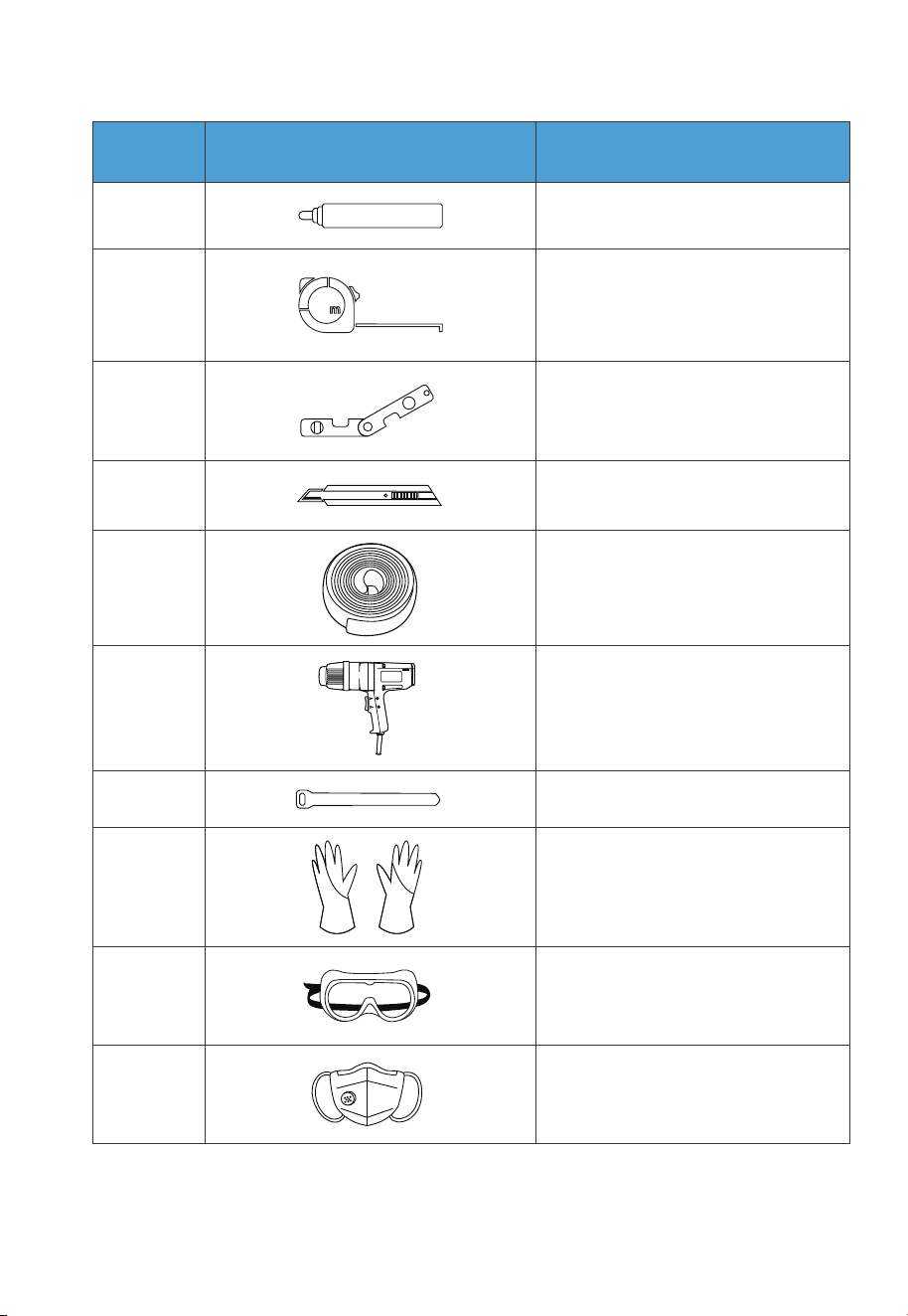
12
11
13
14
15
16
17
18
19
20
Measuring tape
Marker
Level ruler
Box cutter
Heat shrink tubing
Heat gun
Cable tie
Anti-static gloves
Protective goggle
Mask
No. DescriptionPicture
49
JUST POWER ON
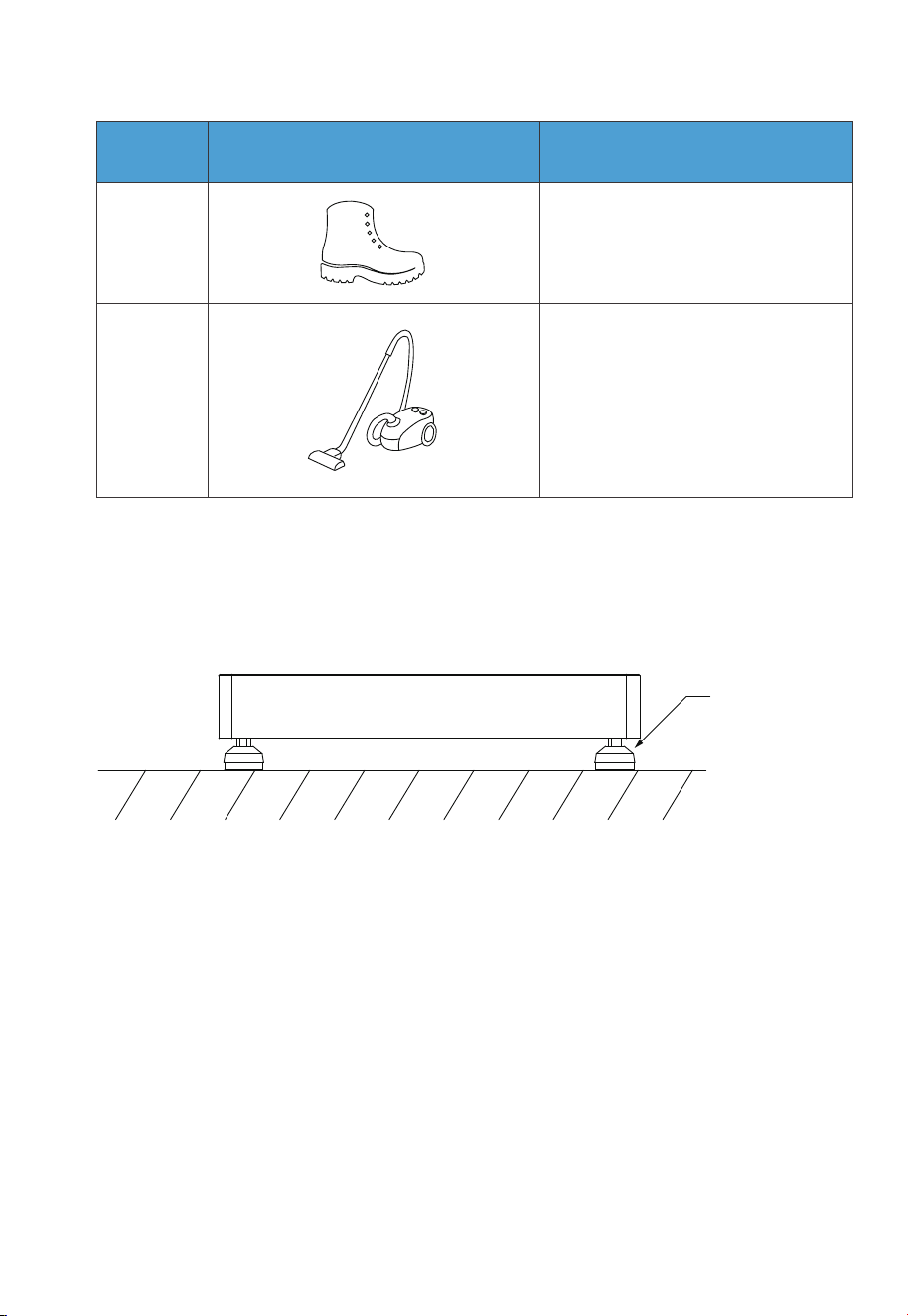
21
Safety-toe shoes
6.6 Installation
Step 1: Place the base on the ground and adjust the height of leveling feet so that
the base stands stably on the ground. Don’t forget to tighten the nuts to
secure the leveling feet.
Step 2: Mark the drilling positions with tape and marker. Drill holes with the electric
drill and insert M8 expansion bolts.
Step 3: Move the B500 battery pack to the base. Two people are required to transport
the B500. Align the bumps on the battery with the notches on the base to
secure the battery in place.
Step 4: Fix 2 brackets #1 to two sides of B500 with 4 M5*10 screws. Put the bracket #2
through the compression rivet screw of bracket #1 and M8 expansion bolts.
Secure the connection with M8 and M5 nuts.
Step 5: Repeat Step 3 and 4 to secure all battery packs.
Step 6: Follow the same steps to install the EP900 inverter on top.
Ground
The height of 4
leveling feet can
be adjusted.
Fig. 6-6
No. DescriptionPicture
22
Vacuum cleaner
50
JUST POWER ON
7. EP900 Home ESS Electrical Connection
Before installation or maintenance, make sure both AC and DC sides are powered
off. After disconnecting a grid-tied inverter, wait for 5 minutes to ensure complete
discharge, as failure to do so may pose safety risks.
Danger
Warning
Before connecting DC electrical components, ensure the DC
switch is turned off.
The installation should only be performed by authorized profes-
sionals.
All cables should be securely connected, have effective insulation,
and meet required specifications.
Incorrect wiring may cause damage to the system.
Fig. 6-7
Ground
Wall
B500
Base
B500
EP900
2.15 in/55mm
51
JUST POWER ON

7.1 B500 Battery Wiring Interface Instructions
Instruction
Ensure that the PV modules connected to the EP900 have an
open-circuit voltage not exceeding 550V and comply with the
IEC 61730A standard.
Attention
The installation and maintenance of the inverter should only be
performed by authorized professional.
When working with grid-tied inverters and batteries, wear rubber
gloves, safety glasses, safety boots, and other protective clothing.
Table 7-1 Current Parameters
Model
EP900 15A / 30A 12.5A / 25A
PV ISC (Absolute / Maximum) Max. Input Current
Interface
Inverter signal port
(PCS LINK)
Battery signal input port
(PACK LINK IN)
Battery signal output port
(PACK LINK OUT)
BAT+ terminal
BAT- terminal
For communication between inverter and battery packs. Only the
top B500 needs to be connected to the LINK PORT 2 of the inverter.
Description
Table 7-2
For communication between battery packs. Connect to the PACK
LINK OUT port of the upper battery when multiple B500s are
stacked (except for the top B500).
For communication between battery packs. Connect to the PACK
LINK IN port of the lower battery when multiple B500s are stacked
(except for the bottom B500).
Connect to the BAT+ terminal of another B500 or the inverter.
Connect to the BAT- terminal of another B500 or the inverter.
52
JUST POWER ON
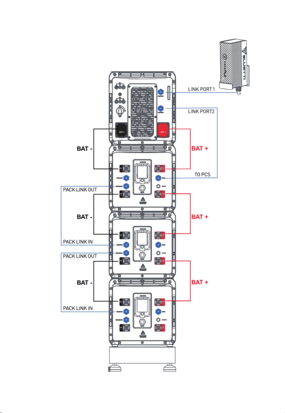
Fig. 6-5
53
JUST POWER ON
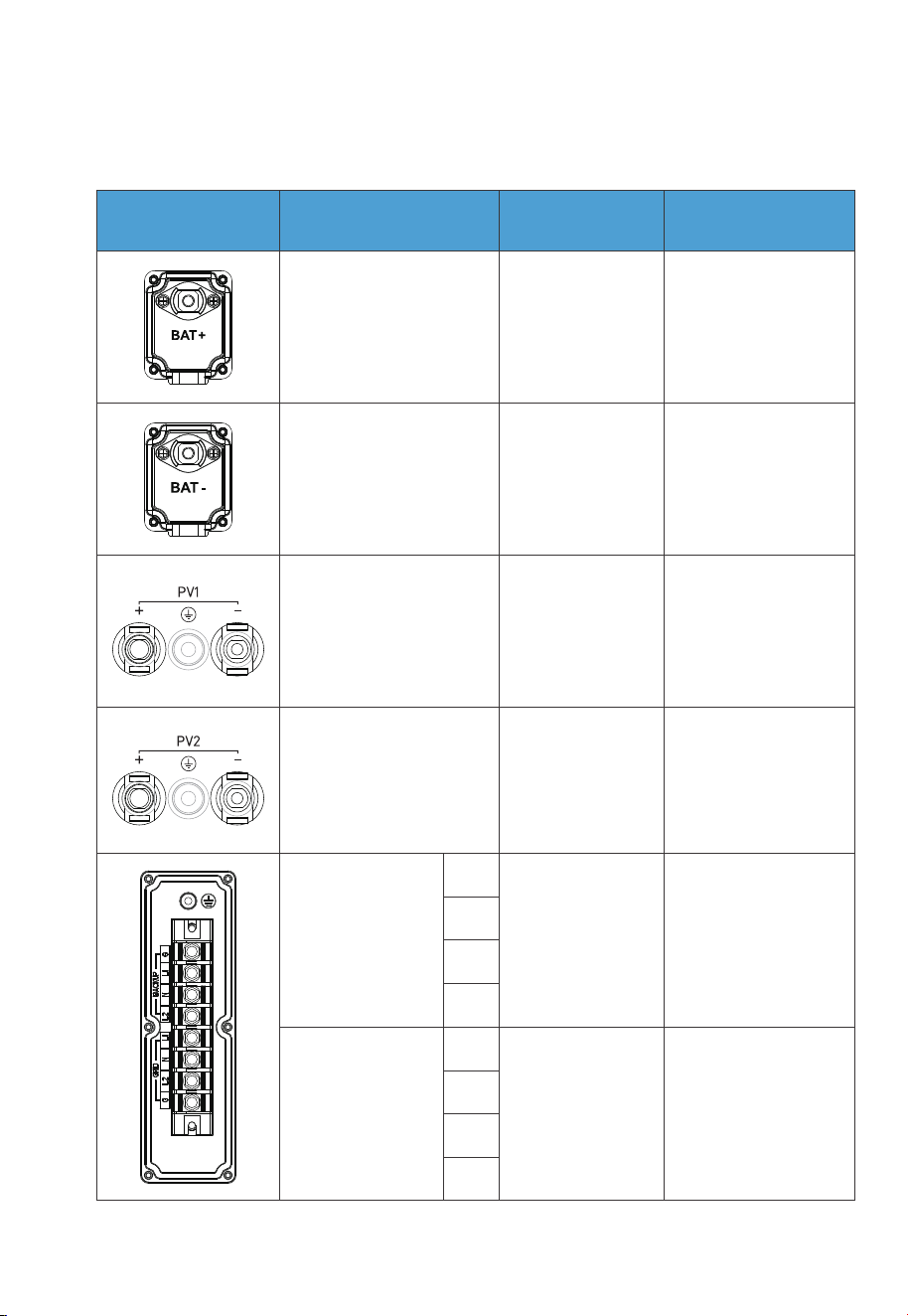
7.2 EP900 Inverter Wiring Interface Instructions
Table 7-3
Conductor cross-
sectional area: 12AWG
(3000W Max.)
Conductor cross-
sectional area: 10AWG
(6000W Max.)
Conductor cross-
sectional area: 6AWG
Conductor cross-
sectional area: 6AWG
Standard
accessories
BAT+: to the battery
BAT+ terminal
BAT-: to the battery
BAT- terminal
Standard
accessories
/
/
Outdoor multi-core
copper cable
Outdoor multi-core
copper cable
Outdoor
multi-core copper
core cable
Outdoor
multi-core copper
core cable
BACKUP
G
L1
N
L2
L1
N
L2
G
GRID
Interface Cable type
Description
Cable specification
PV1+: to the positive
terminal of solar panel
PV1-: to the negative
terminal of solar panel
PV1 G: PV1 grounding
PV2+: to the positive
terminal of solar panel
PV2-: to the negative
terminal of solar panel
PV2 G: PV2 grounding
54
JUST POWER ON
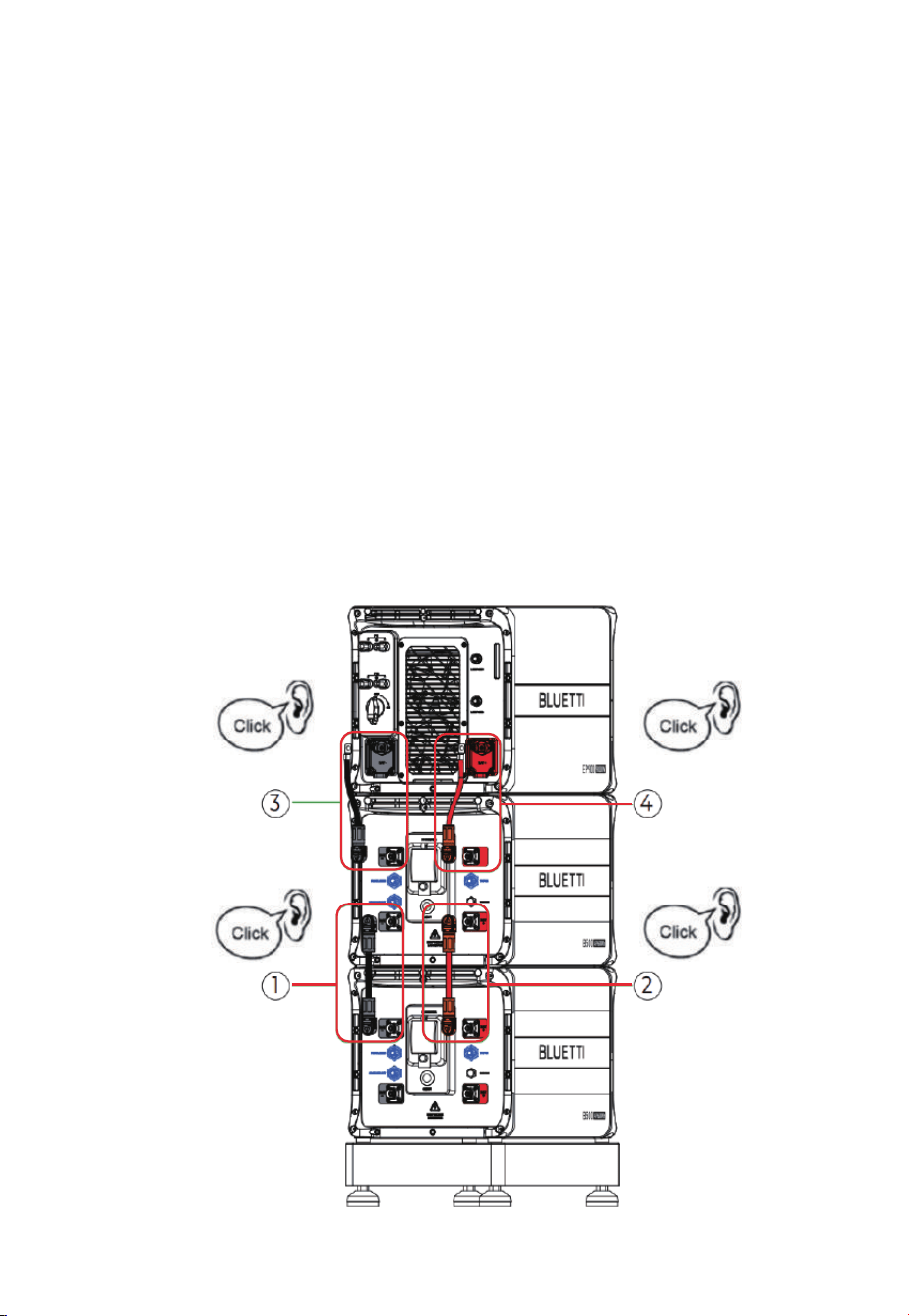
Step 1: Connect two B500 battery packs via the battery expansion cables - black
cable for negative terminals, red for positive terminals.
Step 2: Connect the top B500 to EP900 inverter via the battery power cables - black
cable for negative terminals, red for positive terminals.
• Fix the black battery power cable to the EP900 inverter BAT- terminal with M8 screws.
• Secure the black protection cover with M4 screws. See Fig. 7-2-2.
• Connect the other end of the cable to the B500 BAT- terminal.
• Repeat to connect the red battery power cable. See Fig. 7-2-3.
Recommended torque: Less than 6N m(53 to 58 in-lbs)for M8 screws
1.2N m(11 to 16 in-lbs) for M4 screws.
Step 3: Connect the top B500 to EP900 inverter via the battery power cables - black
cable for negative terminals, red for positive terminals.
7.3 Battery Power Cable
Fig. 7-2-1
55
JUST POWER ON
1
2
3
4
5
Max. Torque: 6N m (53- to 58 in-lbs)
Max. Torque:
1.2N m (11 to 16 in-lbs)
1. Inverter BAT- terminal (Black)
2. Black battery power cable (BAT-)
3. M8*12 screws
4. Black protection cover (BAT-)
5. M4*12 screws
Fig. 7-2-2
Fig. 7-2-3
Max. Torque:
1.2N m (11 to 16 in-lbs)
1. Inverter BAT+ terminal (Red)
2. Red battery power cable (BAT+)
3. M8*12 screws
4. Red protection cover (BAT+)
5. M4*12 screws
1
2
3
4
5
56
JUST POWER ON
Max. Torque: 6N m (53- to 58 in-lbs)
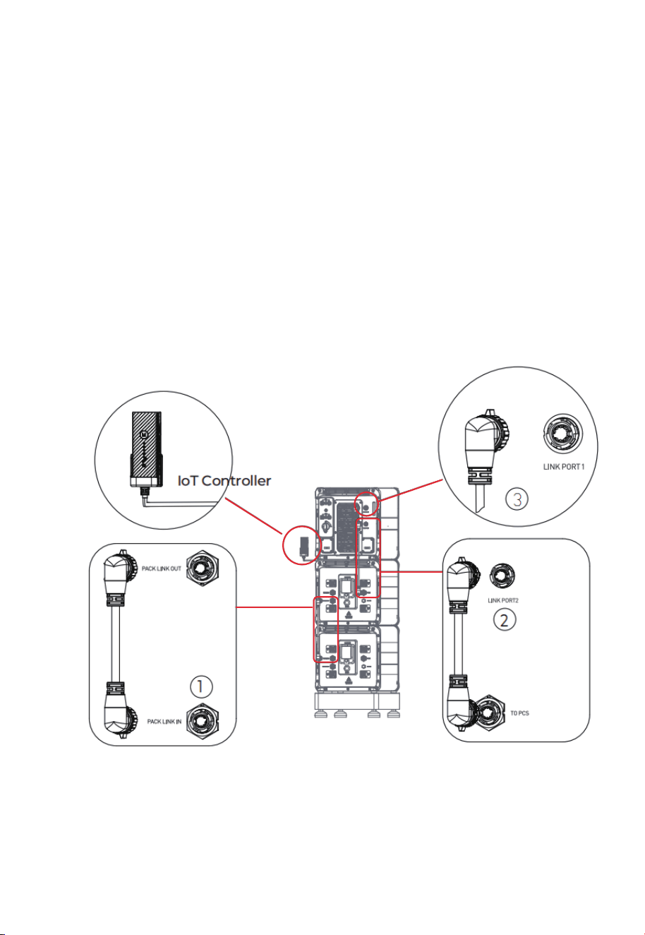
Step 1: To achieve communication between two B500 battery packs, a communica-
tion cable is required. Plug one end of the cable to the B500’s PACK LINK IN
port, and the other to the upper B500’s PACK LINK OUT port. See Fig. 7-3 ① .
Step 2: For communication between the EP900 inverter and B500 battery packs,
plug one end of the communication cable to the top B500’s inverter signal
port (TO PCS), and the other to the LINK PORT 2 of the EP900 inverter. See
Fig. 7-3 ② .
Step 3: Connect the IoT controller to the LINK PORT 1 of the EP900 inverter. See Fig.
7-3 ③ .
Note: For how to integrate multiple B500s to the EP900, please refer to Fig. 7-1.
7.4 Communication Cable
Fig. 7-3
57
JUST POWER ON
Danger
The positive and negative terminals of the PV (photovoltaic) system
inverter should not be grounded, as it may lead to inverter failure.
However, it is important to ground all non-current carrying metal
parts, including brackets, distribution boxes, inverter enclosures,
battery pack enclosures, and other relevant components.
7.5 Grounding Protection (G)
7.5.1 PV Grounding Protection
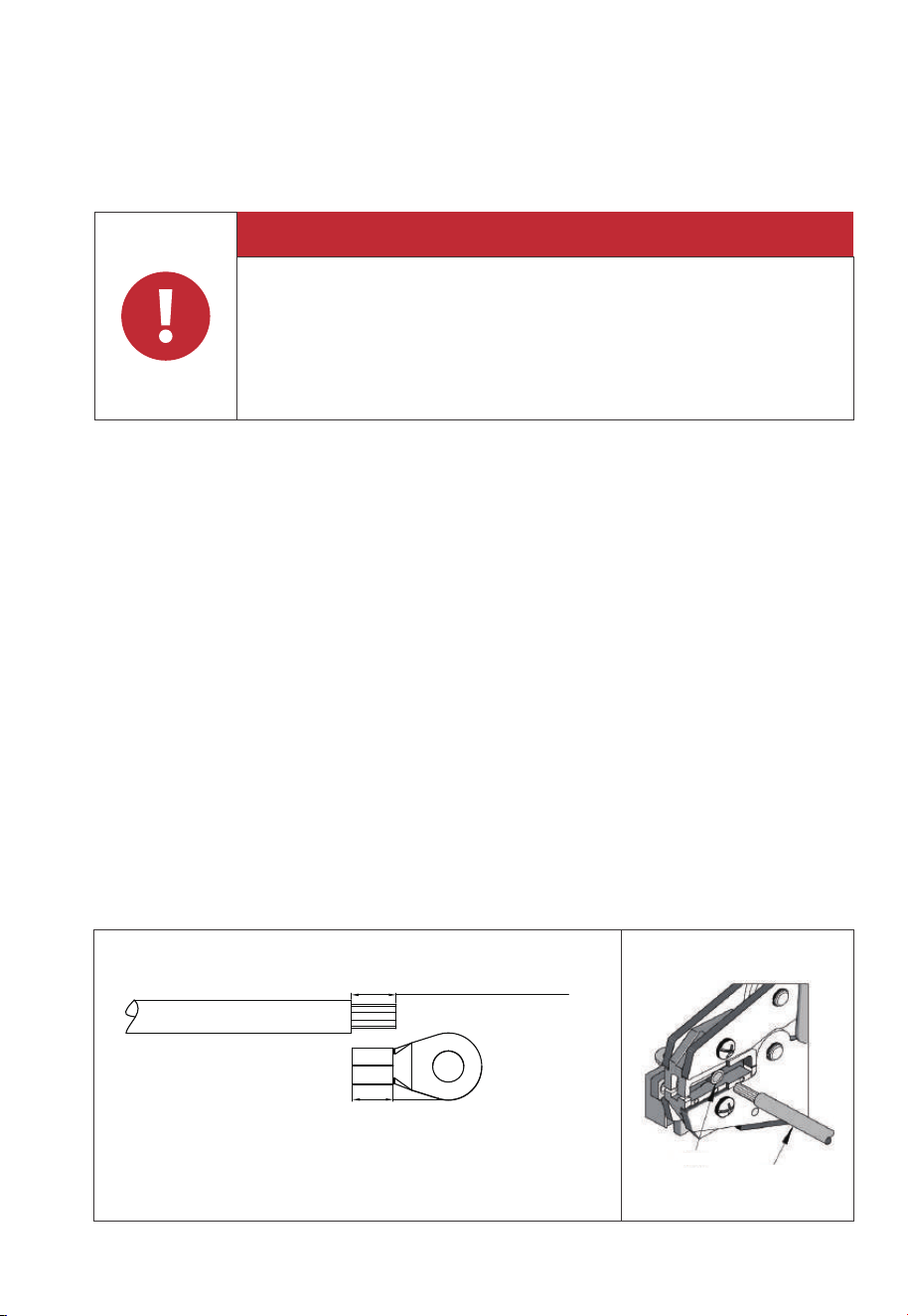
Prerequisite: Prepare the ground cable (recommended to use 12AWG outdoor
power cable and RNB3.5-5S OT terminals).
Step 1: Strip the insulation layer of the ground cable with a cable stripper to a proper
length. See Fig. 7-4-1.
Step 2: Insert the exposed core wires into the OT terminal and crimp them with a
crimper, as shown in Fig. 7-4-2.
Step 3: Fix the OT terminal with M5 screws at the position shown in Fig. 7-4-3.
Recommended tor
que: 3N m(26.55 in-lbs).
Note:
• L3 is the length between the insulation of the cable and the crimped part. L4 is the
length between the crimped part and core wires protruding from the crimped
part.
• The cavity formed after crimping the conductor crimp strip shall wrap the core
wires completely. The core wires shall contact the terminal closely.
L2 is 0.12in/3mm longer than L1
Fig. 7-4-1
L2=L1+0.12in / 3mm
L1
Terminal block
Wire
58
JUST POWER ON
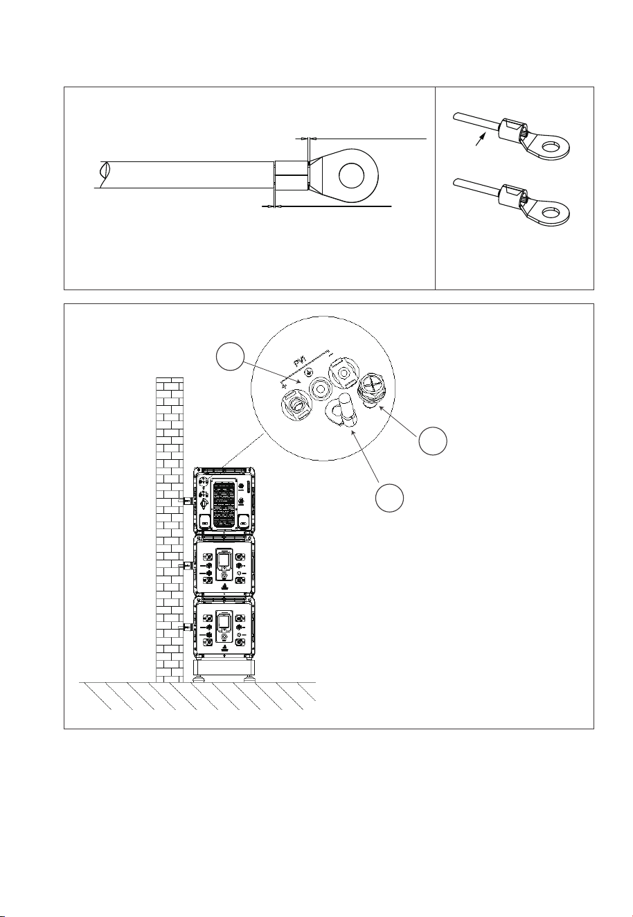
Fig. 7-4-2 Fig. 7-4-3
1
2
3
1 . M5×10 screws
2. OT terminal
3. PV grounding pole
L3˝0.08in / 2mm
L4˝0.04in / 1mm
Visible wire
Wire even or bulge up
to 0.04in / 1mm
Fig. 7-4-4
✔
59
JUST POWER ON
Attention
Before removing the PV input positive and negative connectors,
make sure the DC switch on the inverter has been set to “OFF”.
Danger
Do not connect two PV circuits in parallel. Ensure proper orienta-
tion of PV1 and PV2 cables.
7.5.2 Systems Grounding Protection
7.6 PV Cable
Step 1: It is recommended to use 12AWG and 10AWG outdoor power cables. Discon-
nect the cable connector from the EP900 positive and negative connectors.
(You’re strongly recommend to distinguish the positive and negative connec-
tors with different colors.)
60
JUST POWER ON
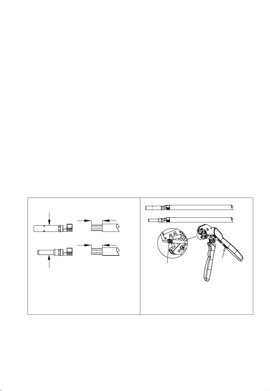
Step 2: Use wire strippers to peel off the insulation layer of the positive and negative
power cables. For the specific stripping length, refer to Fig. 7-5-1.
Step 3: Insert the positive and negative power cables into the positive and negative
metal terminals separately. Crimp them tightly to ensure that the cable can
not be pulled out. See Fig. 7-5-2.
Step 4: Insert the crimped positive and negative power cables through the locking
nut and into the corresponding plastic housing until you hear a click, which
indicates that the metal core has been snapped into place, and then tighten
the locking nut. See Fig. 7-5-3 and Fig. 7-5-4.
Step 5: Use a multimeter to confirm the positive and negative poles. See Fig. 7-5-5.
The positive and negative connectors can then be inserted into the PV input
of EP900 inverter. See Fig. 7-5-6.
If you need to remove the PV positive and negative connectors from the inverter,
use a removal crimper to insert the bayonet as shown in Fig. 7-5-7, and press down
to remove the connectors.
1 . Positive metal terminal
2. Negative metal terminal
0.276-0.354(in)/
7-9mm
0.276-0.354(in)/
7-9mm
2
1
Crimper
Press
Fig. 7-5-1 Fig. 7-5-2
61
JUST POWER ON
1. Positive metal terminal
MC4 Wrench
2. Negative metal terminal
Remove the PV connector
1
2
Fig. 7-5-5
Fig. 7-5-7
Fig. 7-5-6
Fig. 7-5-3 Fig. 7-5-4
62
JUST POWER ON

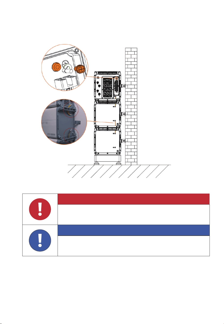
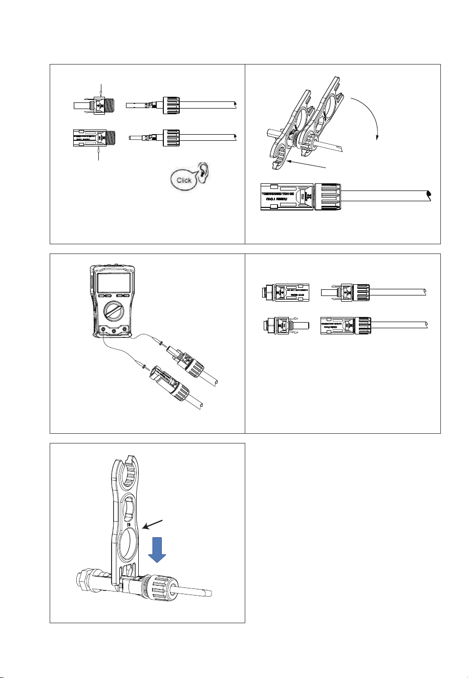
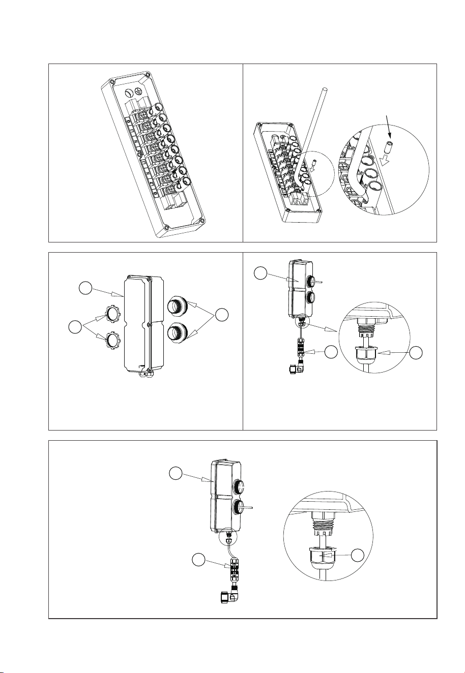
7.7 GRID and BACKUP Cables
Prerequisite: Prepare neutral, live, and grounding wires (recommended colors: white,
red ,black, green; use 6AWG outdoor power cables).
NOTE: Please connect the Ground cable first,before connect other cables !
Step 1: Select the appropriate type and size of cables (see table 7-2). Strip the cables
with a length of 0.8 inches, as shown in Fig. 7-6-1.
Step 2: When opening the junction box, inspect the terminal strip and connection
label as shown in Fig. 7-6-2.
Step 3: Connect the 6AWG BACKUP cable as labeled (G, L1, N, L2) in the BACKUP
section of the junction box. Secure it using an H3 hex screwdriver, as shown in
Fig. 7-6-3.
Step 4: Connect the 6AWG GRID cable as labeled (L1, N, L2, G) in the GRID section of
the junction box. Secure it using an H3 hex screwdriver, as shown in Fig. 7-6-3.
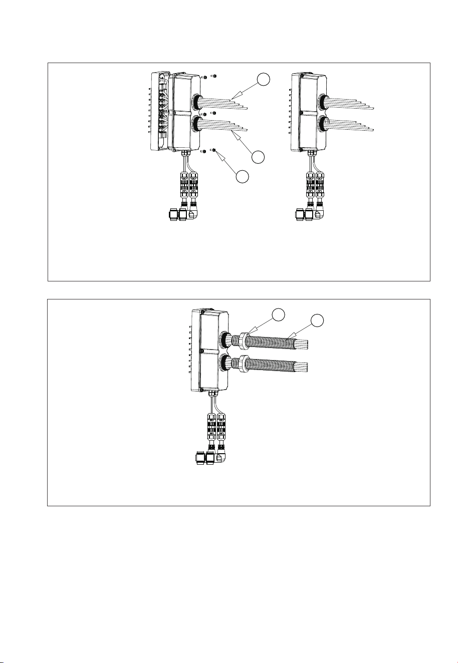
Step 5: Attach the PG waterproof connector to the AC cable protection case. Tighten
the hexagon nut at the bottom with a socket tool, as shown in Fig. 7-6-4.
Step 6: Thread the DRMs communication cable through a PG connector, emerging
from the upper hole of the case, as shown in Fig. 7-6-5.
Step 7: Thread the CT communication cable through a PG connector, emerging
from the lower hole of the case, as shown in Fig. 7-6-6.
Step 8: Pull out the BACKUP and GRID cables and securely fasten the protection
case to the junction box using M4*12 screws, as shown in Fig. 7-6-7.
Step 9: Slide the PG connector compression nut onto the hose and thread the
BACKUP and GRID cables through the hose. Tighten the nut to the protec-
tion case as shown in Fig.7-6-8.
0.8in
Fig. 7-6-1
63
JUST POWER ON
M
6 screws
(Tool: M3 hex screwdriver)
Max. Torque:3.0N m
(26.55 in-lbs)
Fig. 7-6-2 Fig. 7-6-3
1. A
C cable protection case
2. Hose connection nut
3. Waterproof conductor(3/4 inch)
1. AC cable protection case
2. Hose connection nut
3. CT communication cable
1. AC cable protection case
2. Hose connection nut
3. DRMs communication cable
1
1
3
2
3
1
2
3
2
Fig. 7-6-5Fig. 7-6-4
Fig. 7-6-6
64
JUST POWER ON
1. BACKUP cables & DRMs c
ommunication cable
2. GRID cables & CT communication cable
3. M4*12 screws, Max. Torque: 1.2N m(10.62 in-lbs)
1
2
3
Fig. 7-6-7
Fig. 7-6 Load Cable Connection
1. PG connector compression nut
2. Hose
1
2
Fig. 7-6-8
65
JUST POWER ON
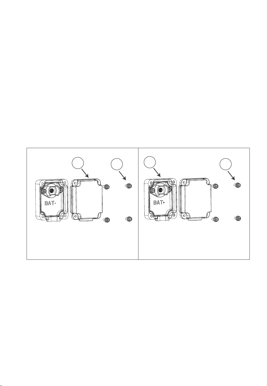
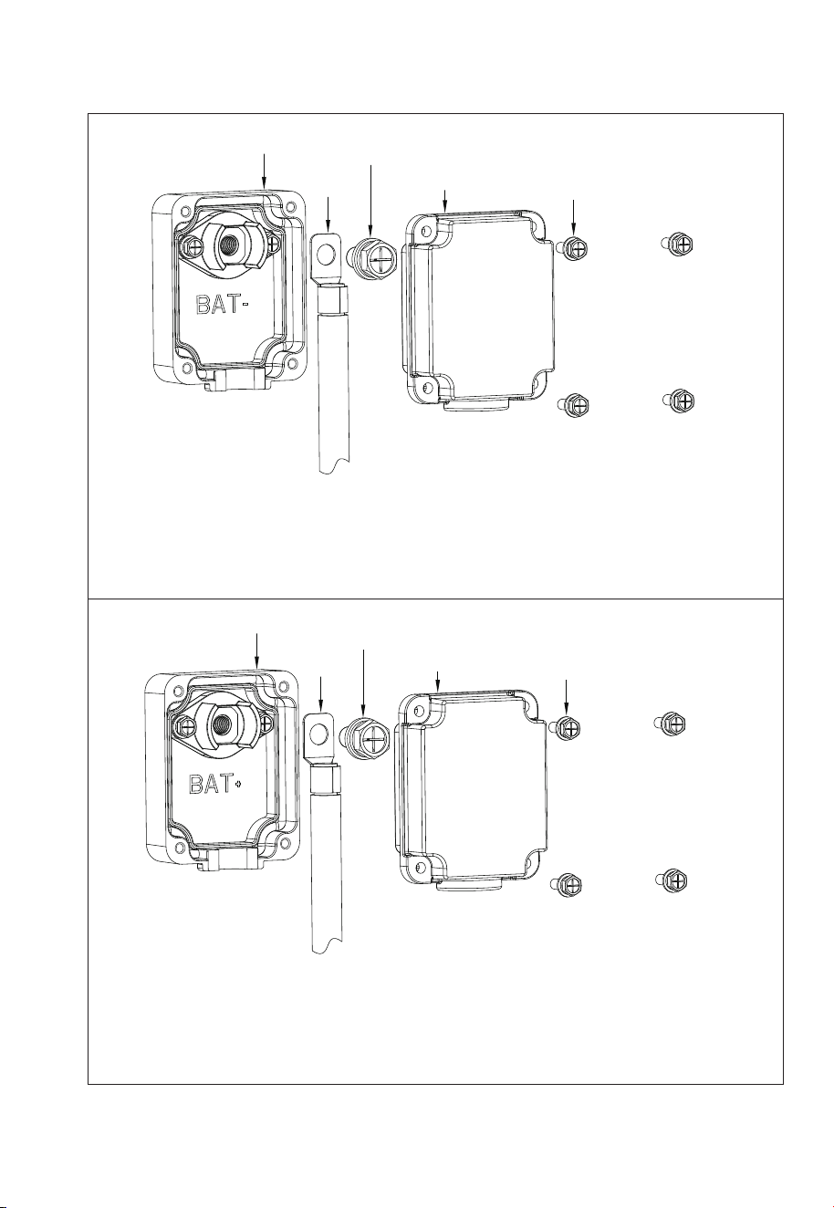
7.8 Battery Terminal
Step 1: Use a cross screwdriver to remove the positive and negative terminal protec-
tion covers of the battery, see Fig. 7-7-1 and Fig. 7-7-2.
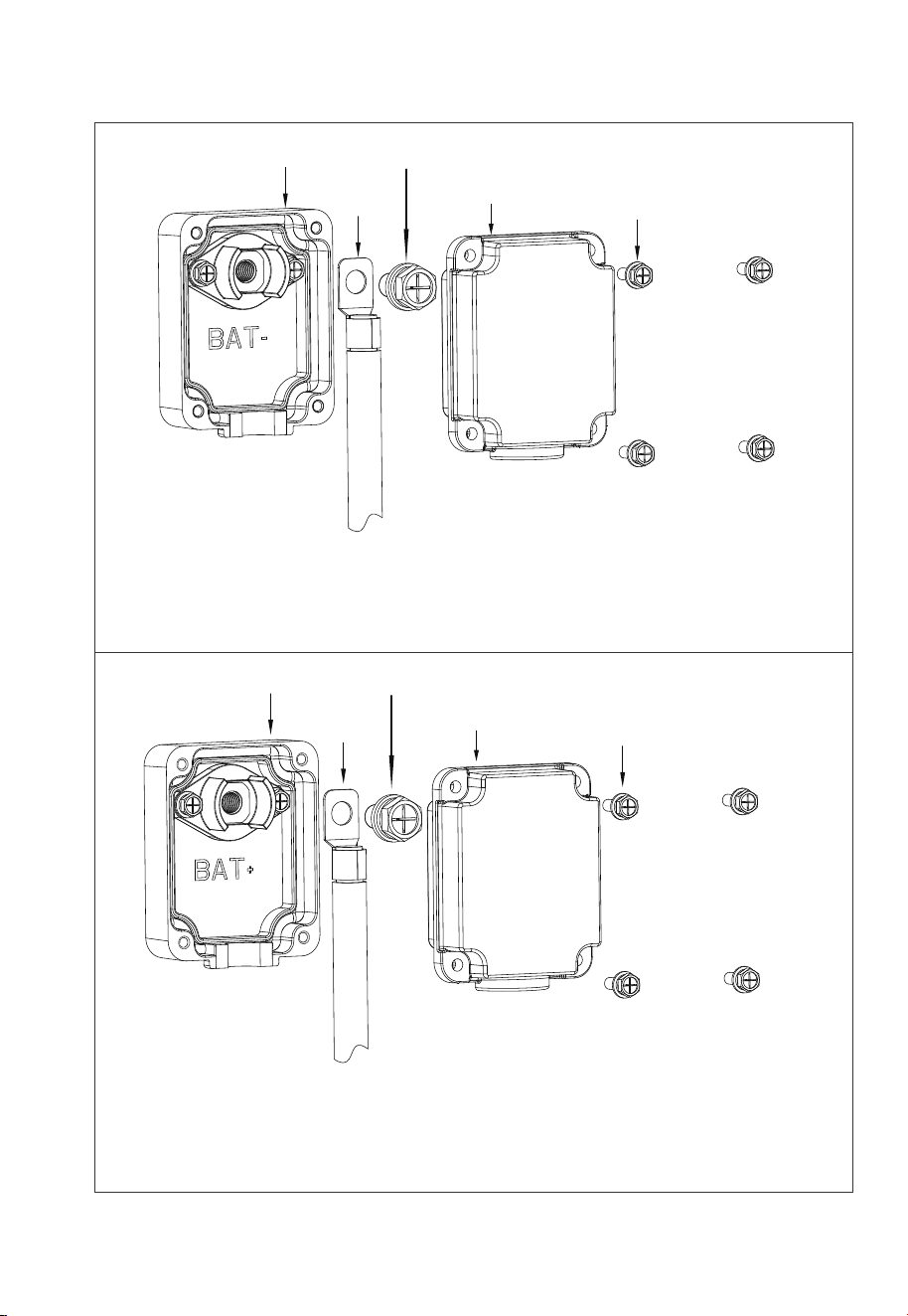
Step 2: Connect two B500 battery packs via the battery expansion cables - black
cable for negative terminals, red for positive terminals.
• Fix the black battery expansion cable to the B500’s BAT- terminal with M8 screws.
• Secure the black protection cover with M4 screws. See Figure 7-7-3.
• Repeat to connect the red battery expansion cable. See Figure 7-7-4.
Recommended tor
que: 6N m (53.10 in-lbs)for M8 screws
1.2N m(10.62in-lbs) for M4 screws.
Step 3: The battery packs are properly connected.
Fig. 7-7-1 Fig. 7-7-2
1. Black protection cover (BAT-)
2. M4*12 screws
1. Red protection cover (BAT+)
2. M4*12 screws
1
2
1
2
66
JUST POWER ON
1
2
3
4
5
Max. Torque: 6N m (53- to 58 in-lbs)
Max. Torque:
1.2N m (11 to 16 in-lbs)
1. Inverter BAT+ terminal (Red)
2.Red battery power cable (BAT+)
3.M8*12 screws
4.Red protection cover (BAT+)
5.M4*12 screws
1.Inverter BAT- terminal (Black)
2.Black battery power cable (BAT-)
3.M8*12 screws
4.Black protection cover (BAT-)
5.M4*12 screws
1
2
3
4
5
Max. Torque: 6N m (53- to 58 in-lbs)
Max. Torque:
1.2N m (11 to 16 in-lbs)
Figure 3-6 BAT+ and BAT- connection
Fig. 7-7-3
Fig. 7-7-4
67
JUST POWER ON
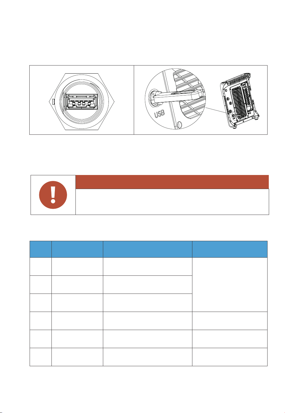
Operation by professional personnel. For USB drive access only,
not for USB charging.
7.9 Other Ports
7.9.1 USB
7.9.2 DRMs Port (Generator + Meter)
Fig. 7-8
The port is used for EP900 inverter firmware upgrade.
The USB drive should be formatted as FAT32 with no more than 32GB in size.
Note: Pin 4, 5, and 6 are for communication with the electric meter. Refer to the
meter’s user manual for wiring details..
Warning
Table 7-4
PIN Category Definition Specifications
6
B: RS485 differential signal -
485-B3 (Orange)
5
A: RS485 differential signal +
485-A3 (Yellow)
4
Signal ground
INS GND (White)
2
External DC input limit:
30VDC / 3A.
(For generator input)
Single-pole & double-throw
relay normally closed output
3
Single-pole & double-throw
relay normally open output
GEN NO (Green)
GEN NC (Black)
1
Connect to meter A2
Connect to meter B2
/
Single-pole & double-throw
relay common terminal
GEN
COM (Red)
68
JUST POWER ON

7.9.3 LINK PORT 1 & LINK PORT 2
Note: Refer to Section 5.3 for installation instructions of the grid communication
module and IoT controller.
Table 7-5
Interface Function Note
Refer to Fig. 7-2 for details.
Link Port 1
Link Port 2
Connect the IoT controller
Connect the battery pack
PIN Definition Function
485-A5
485-B5
INS_12V
INS_GND
A: RS485 differential signal +
B: RS485 differential signal -
WiFi power source
WiFi power source grounding
Connect to WiFi
Connect to WiFi
/
/
Table 7-6
7.9.4 Grid Communication Module
69
JUST POWER ON

Step1: Rotate the M20 6-pin connector cap counterclockwise and take it off.
Step2: Put the CT communication cable through the connector cap. Identify the
connector pins and connect the signal wires according to the table below.
Step3: Tighten the screws with a screwdriver.
Step 4: Make sure the cables are secured until they can’t be pulled out.
Step 5: Tighten the connector cap and nut clockwise.
7.9.5 CT Port
Table 7-7
PIN Definition Function Remarks
6
5
4
2
3
1
/
Connect to the
Phase L2 CT in the grid.
Connect to the
Phase L1 CT in the grid.
CT-L1+ (White)
CT-L1- (Black)
CT-L2+ (White)
CT-L2- (Black)
NC
NC
CT output positive terminal
CT output negative terminal
CT output positive terminal
CT output negative terminal
/
/
Pin
Wire
1
Red
2
Black
3
Green
4
White
5
N/A
70
JUST POWER ON
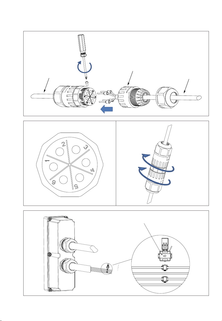
Fig. 7-9
CT cable
Tighten the screws
CT communication cable
Connector cap
The arrow points to the grid.
GRID-L1
GRID-N
GRID-L2
G
71
JUST POWER ON
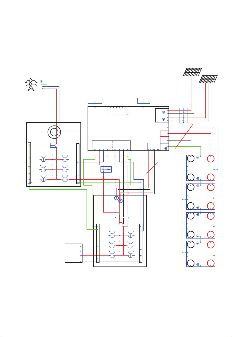
Follow the diagram below for the correct CT direction from the grid-tied inverter to
the grid.
Fig. 7-10 Partial bac
kup system
Main Panel
Load
G N
Sub Panel
Transfer
Switch
Standard cable
Standard cable
L1
L2
L2
L1
L1
L2
EP900
PV1
PV2
+
-
+
-
BAT+
BAT-
DRMs
1
2
3 4 5 6
CT
21
34 56
BACKUP
GRID
L1L2 NG
L1
L2
N G
6000W
3000W
B500
BAT- BAT+
BAT-
TO PCS
BAT+
PACK LINK OUT
PACK LINK IN
B500
BAT- BAT+
BAT-
TO PCS
BAT+
PACK LINK OUT
PACK LINK IN
B500
BAT- BAT+
BAT-
TO PCS
BAT+
PACK LINK OUT
PACK LINK IN
B500
BAT- BAT+
BAT-
TO PCS
BAT+
PACK LINK OUT
PACK LINK IN
IOT box
meter
G
N
L1 L2
L1
L2
N
L1
L2
F1
QF2
F6
QF1
CT2
CT 1
F2
F3
F4
F5
F7
F8
F9
2
1
4
3
1 2
3 4
1 2
3 4
WIFI box
L1
L2
N
GND
LINK PORT1
LINK PORT2
COM
12AWG
10AWG
10AWG
12AWG
PV1
PV2
6AWG6AWG
L1
N
L2
Grid
72
JUST POWER ON
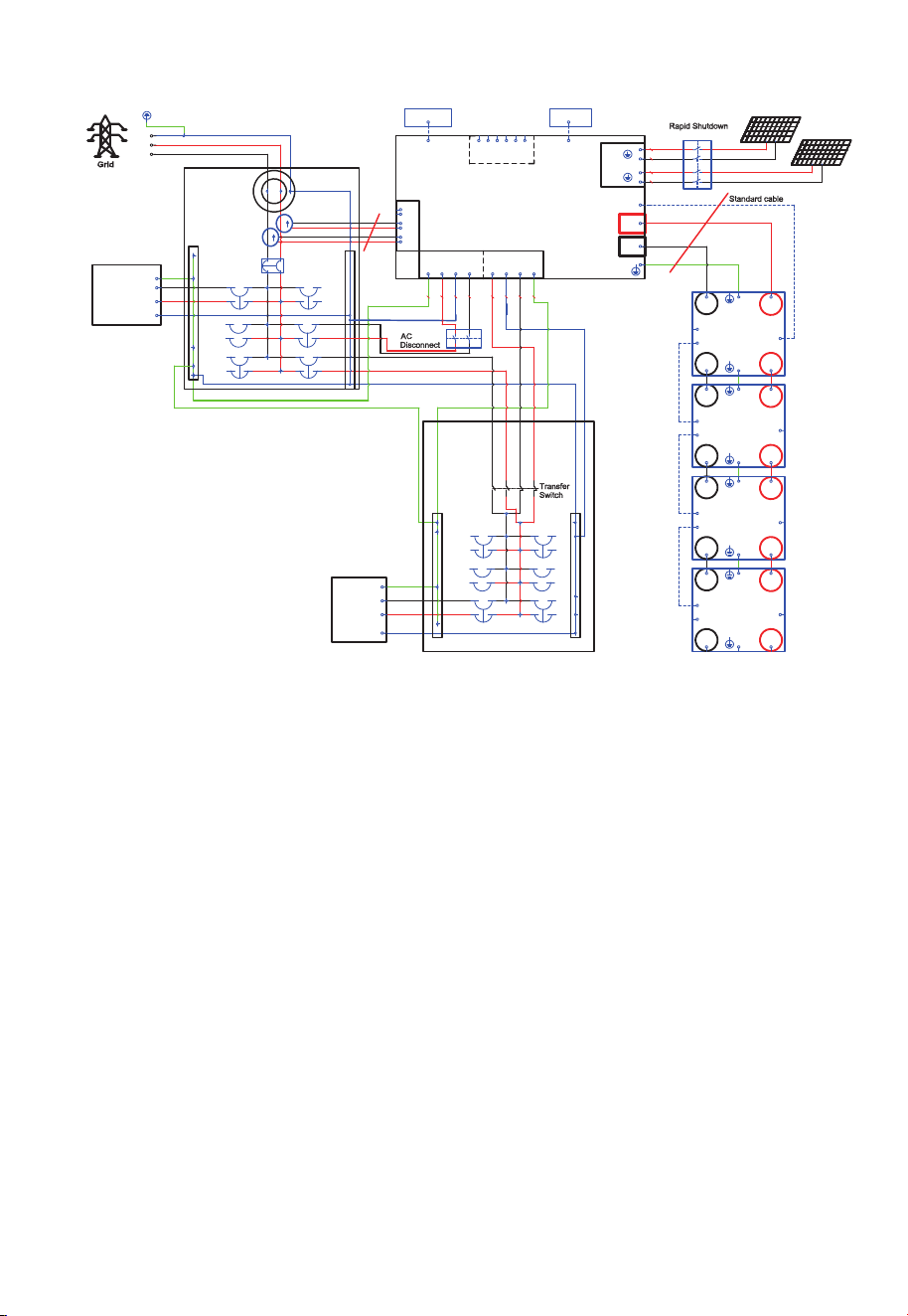
Fig. 7-11 Self-Consu
mption and Partial backup system
GND
N
L1 L2
meter
QF1
Main Panel
G N
L1
L2
L2
L1
EP900
PV1
PV2
DRMs
6000W
B500
BAT- BAT+
BAT-
TO PCS
BAT+
PACK LINK OUT
PACK LINK IN
B500
BAT- BAT+
BAT-
TO PCS
BAT+
PACK LINK OUT
PACK LINK IN
B500
BAT- BAT+
BAT-
TO PCS
BAT+
PACK LINK OUT
PACK LINK IN
B500
BAT- BAT+
BAT-
TO PCS
BAT+
PACK LINK OUT
PACK LINK IN
WIFI box
IOT box
F1
2
1
4
3
CT1
CT2
L1
L2
L1
L2
QF2
Load
L1
L2
N
GND
High
power
Load
BACKUP
GRID
CT
2
1
3
4
5
6
L1
L2
NG L1L2 N G
F2
F3
F4
F5
F6
F7
F9
3000W
1 2
3 4
1 2
3 4
+
-
+
-
BAT+
BAT-
1
2 3 4
5
6
LINK PORT1
LINK PORT2
COM
12AWG
10AWG
10AWG
12AWG
6AWG6AWG6AWG6AWG
L1
L2
N
GND
L1
N
L2
6AWG6AWG
6AWG
6AWG
N
PV1
PV2
standard
cable
Sub Panel
73
JUST POWER ON

8.1 Preliminary Check
Check the followings before first use.
• Confirm that all components of the system are installed according to specific
requirements.
• Make sure the Ground, PV+ / PV- and BAT+ / BAT- cables are connected with
correct polarity and proper voltage.
• Switch off all AC and DC circuit breakers.
• Circuit breakers should be selected according to the requirements of this manual
and local regulations.
• Make sure grid and load cables are held firmly in place.˜
• All safety signs and warning labels shall be firmly attached and clearly visible when
needed.
8
.2 Power on
Step 1: Switch on the DC circuit breakers on B500 battery packs.
Press and hold the power button of any battery pack for 3 seconds
and the green indicator on the button lights up
Step 2: Wait for 40 seconds until the green indicator of the inverter is always on.
Step 3: Switch on the AC circuit breakers connected to the EP900 grid port
Step 4: Switch on the DC switch on EP900.
Step 5: Power on the system via the BLUETTl app. For details, please refer to
App manual.You can check the EP900 system status through the app.
Step 6: Check the voltage of BACKUP port
Step 7: Switch on the AC circuit breakers connected to the EP900 load port.
8.3 Firmware Upgrade
8.3.1 USB Upgrade
Step 1: Connect the USB drive to a USB port on your computer.˜
Step 2: Download the upgrade file*, unzip and store it on the USB drive.
Step 3: Connect the USB drive to the USB port on EP900.
Step 4: Power on EP900.
Step 5: The firmware upgrade starts automatically once the upgrade files are
detected.
8. System Check
74
JUST POWER ON

Table 8-1
There is still residual voltage after the EP900 is powered off, which
may cause electric shock or burns. Please wait at least 30 minutes
before operating the system.
Warning
Step 6: The buzzer beeps after the firmware is updated successfully. Please unplug
the USB drive, or EP900 will report a USB Format Error.
Step 7: Pair EP900 with BLUETTI app, then you can check the firmware version in
System information>>Firmware version. If any of the following occurs, please
try the solutions provided. If the symptom persists after 5 attempts, contact
BLUETTI support.
* Please contact BLUETTI support for further assistance.
8.3.2 OTA Upgrade
The EP900 Home ESS also supports OTA firmware upgrade. For details, please refer
to “Firmware Upgrade” in the EP900 Energy Storage System BLUETTI App User
Manual.
8.4 Power off
Step 1: Turn off the System Switch on BLUETTI APP.
Step 2: Switch off the AC circuit breakers connected to the inverter GRID and
BACKUP terminals.
Error Description
USB Upgrade Failed.
USB Format Error
Firmware version not
updating or abnormal.
Please contact BLUETTI support.
Solution
1. Make sure the USB is formatted as FAT32 with no
more than 32GB in size.
2. Check if the upgrade files exist or expire. Please
download the latest upgrade files.
Please download the latest upgrade files. If the
symptom persists, contact BLUETTI support.
75
JUST POWER ON

9.1 Remove the Inverter
When the inverter is no longer in use, it must be disposed of properly.
Step 1: Power off the system.
Step 2: Please turn off the Breaker of the entire EP900 energy storage system first.
Disconnect all electrical connections to the inverter, such as signal cable, DC input
cable, power cable, AC output cable, grounding cable, etc.
Step 3: Remove the inverter and related parts.
9.2 Recycle the Inverter and Battery Pack
When the battery pack reaches the end of its lifespan,˜it˜must be safely and carefully
disposed˜of˜by the provisions of local laws and˜regulations.
Please contact our company for further assistance if the battery pack is
a.Leaked or damaged.
b.Out of warranty or severely degraded in performance.
c.To be replaced or not intended for further use.
9. System Disposal
Step 3: Switch off the inverter PV breaker.
Step 4: Press the power button on any B500 till the indicator on the button flashes
green.
Step 5: The indicator continues to flash.
Step 6: When the indicator is off, B500 battery packs turn off.
Step 7: Switch off main switches for all B500s and the system powers off.
76
JUST POWER ON

10. Troubleshooting
Table 10-1
Error DescriptionNo. Solution
B001
B002
B003
B004
B005
B006
B007
B008
B009
B010
B011
B012
B013
B014
B015
B016
B017
B018
B019
B020
B021
B022
BUS Overvoltage
BUS2 Overvoltage
BUS Undervoltage
BUS2 Undervoltage
Hardware BUS Overvoltage
Hardware BUS2 Overvoltage
Hardware Battery Overvoltage
Hardware Inverter Overcurrent
Hardware Inverter2 Overcurrent
Hardware LLC1 Input Overcurrent
Hardware LLC2 Input Overcurrent
/
Auxiliary Power Undervoltage
DC Component Exception
Relay Failure
PV Connection Error
PV1 Overcurrent
PV2 Overcurrent
/
PV1 Voltage High
PV2 Voltage High
/
Turn off the inverter and wait 30 minutes
to restart it. If the symptom persists,
please contact BLUETTI support.
Turn off the inverter and wait 30 minutes
to restart it. If the symptom persists,
please contact BLUETTI support.
Check if the total voltage of solar panels
exceeds the limit. Reduce the number of
solar panels, and the inverter resumes
operation after calibration.
Check the insulation resistor between solar
array and grounding for a short circuit.
PV1 ISO FailureB023
B024
-B025
/ /
/
/
/
77
JUST POWER ON

Error DescriptionNo. Solution
B026
B027
B034
B035
B040
B041
B042
B043
B044
B045
B046
Turn off the inverter and wait 30 minutes
to restart it. If the symptom persists, please
contact BLUETTI support.
Hardware PV1 Failure
Hardware PV2 Failure
/
/
/
/
/
/
/
/
/
Hardware Input Overcurrent
DC Input Voltage Low
B050
B051
BMS Communication Interrupted
IoT Communication Interrupted
Inverter Overload
L2 Inverter Overload
/
L1 Inverter Output Failure
L2 Inverter Output Failure
/
/
B032 Fan Failure
B033
Zero Drift Abnormal
(Sampling zero abnormal)
Turn off the inverter and wait 30 minutes
to restart it. If the symptom persists, please
contact BLUETTI support.
B047 Communication Failure
Turn off the inverter and wait 30 minutes
to restart it. If the symptom persists, please
contact BLUETTI support.
Check that the external communication
terminals are connected correctly and restart
the device. If the symptom persists, please
contact BLUETTI support.
B049 DSP Communication Interrupted
Check if the grid connection meets the
installation requirements.
Phase Sequence ErrorB031
Check if the DC voltage is inconsistent with
the battery specifications.
DC Input Voltage High
/ /
/
B036
B048 /
Check if the inverter fan operates well.
Check if the DC voltage is too low.
Check if the inverter is overloaded.
B028-
B030
B037-
B039
78
JUST POWER ON

Error DescriptionNo. Solution
/
/
/
/
/
/
Please make sure use the system within specific
temperature range. Restart the inverter. If the
symptom persists, please contact BLUETTI
support.
Check the PV setup for proper working
condition. Solar panels may get a low voltage
under improper working conditions.
If it occurs occasionally, the grid may go
through abnormal working conditions. The
inverter recovers after the grid resumes.
If it occurs many times, check if the grid voltage
and frequency support the inverter input
specifications. Check the inverter AC circuit
breaker and connections.
If the voltage and frequency are beyond the
range, please contact BLUETTI support.
Check the details on BLUETTI app.
B054
B055
B056
B057
B058
B059
B060
B061
B062
B097
B098
B099
B100
B101
B102
B103
B104
B105
B106
B107
B108
B109
/
Operating Ambient Environment
Temperature 1 Abnormal
Temperature 2 Abnormal
Temperature 3 Abnormal
Temperature 4 Abnormal
BMS Charge Protection
BMS Discharge Protection
BMS System Failure
/
Grid Voltage High
Grid Voltage Low
Grid Frequency High
Grid Frequency Low
/
Grid Loss
PV1 Voltage Low
PV2 Voltage Low
/
/
DSP_Debug CAN Communication Failure
DSP_Debug RS485 Communication Failure
Grid-tied reconnection abnormal
B063-
B096
B052
B053
Zero Drift Abnormal-ARM
RTC Read and Write Abnormal
Turn off the inverter and wait 30 minutes to
restart it. If the symptom persists, please
contact BLUETTI support.
79
JUST POWER ON

Error DescriptionNo. Solution
/
//
Please reconfigure the settings on
BLUETTI app. If the symptom persists,
please contact BLUETTI support.
B129
EEPROM Read and
Write Anomaly
Reserved
B130-
B133
B110-
B128
The USB is formatted as FAT32 with no more than
32GB in size. Check if the upgrade files exist or
expire.
Turn on the inverter again. If the symptom
persists, please contact BLUETTI support.
B134 USB Format Error
Check that the CT connection direction and phase
sequence are correct. If the symptom persists,
please contact BLUETTI support.
B139 CT Connection Direction Error
Turn on the inverter again. If the symptom persists,
please contact BLUETTI support.
B141 Arc pulling module self-test failure
Turn on the inverter again. If the symptom persists,
please contact BLUETTI support.
Turn on the inverter again. If the symptom persists,
please contact BLUETTI support.
Turn on the inverter again. If the symptom persists,
please contact BLUETTI support.
B142
Arcing Module
Communication Failure
Check whether the meter is powered and whether
the communication cable between the meter and
the EP900 energy storage system is connected
normally. If the problem persists, please contact
technical support.
B140 Meter communication Failure
B135
B136
B137
B138
B143
B144
B145
B150
B151
B146-
B149
USB Upgrade Abnormal
Arcing Detection Abnormal
USB Communication Abnormal
USB No Upgrade File
Data Clearing
WiFi Module Communication Loss
WiFi Module Network Configuration Failure
/
Battery Charging Prohibited
Battery Discharging Prohibited
80
JUST POWER ON

11. Specifications
Table 11-1
AC (Grid-tied)
Item
Wiring
Rated Voltage
Voltage Range
Rated Output Current
Input Frequency
Input Frequency Range
Description Note
L1/L2/N/G
120VAC / 240VAC
105V-132V / 211V-264V
37.5A rms
60Hz
55Hz-65Hz
Protection
Anti-islanding protection
Output overcurrent protection
Short-circuit protection
Bypass + Grid Charging
If only two B500 units
are connected, the max.
output is 7600W
Grid - Battery - Grid
PV connected to the
battery side, no residue
current detection.
Max. Input Current
<3%
<10ms
>85% (AC / AC)
/
/
/
/
/
/
/
/
/
Bypass + Grid Charging
If only two B500 units
are connected, the max.
input is 6000W.
Max. Input Apparent Power 13920VA
9000W
58A
Power Factor (PF)
0.9 leading - 0.9
lagging adjustable
Current THD (Rated Power)
On and Off-Grid Switching Time
Round-trip Efficiency
Rated Output Power (240V)
81
JUST POWER ON

Note
Note
AC (Off-Grid)
Item
Output Voltage
Output Frequency
Inversion Efficiency
Output Voltage THD
Description
120V/240V
60Hz
94.4% Peak
<3%
Item Description
Protection
Reverse polarity protection
Insulation resistance detection
Arcing detection
PV Input
Max. Input Power
MPPT Channel
Array in Series
Max. Input Voltage
MPPT Voltage Range / Rated
Single MPPT Max. Input Current
Single MPPT Max. Short-circuit Current
MPPT Efficiency
PV Inversion Efficiency
9000W
2
1 / 2
550V
150V-500V / 360V
12.5A / 25A
15A / 30A
99.9%
96.0% Peak
/
/
/
/
/
/
If only two B500 units
are connected, the max.
output is 7600W.
/
/
/
/
/
/
/
Protection
Output overcurrent protection
Short-circuit protection
Over temperature protection
Overload
13500VA (10s),
9900VA (10min)
Purely resistive load
3000W + 6000W
3000W + 6000W
9000WRated Output Power
82
JUST POWER ON

General
Item
Relative Humidity
Static Power
Standby Power
Operating Temperature
Noise
Cooling
Protection Grade
Working Altitude
Dimensions (L × W × H)
Net Weight
Communication
Warranty
Description
5%-95%
18W
36W
-4°F to 122°F / -20°C to 50°C
˙50dB (A)
Forced air cooling
NEMA 4X
<6561.68ft / 2000m
25.0 × 12.8 × 14.6in / 636 × 325 × 370mm
92.59lbs / 48kg
USB / WiFi / Bluetooth
10 years
System
Inverter
UL9540
UL1741
Item Description
Compliance and Certification
Emissions
Transient Protection
Others
FCC Part 15 Class B
IEEE C62.41 Class B
IEEE1547, IEEE2030.5
California Rule 21
Grid Connections
NEMA 4X, CEC Efficiency,
California Proposition65
83

Table 11-2
Rated Capacity 4960Wh
Charging: 0.5C / 3.6V / 0.05C
(77°F / 25°C)
Discharging: 0.5C / 2.5V
(77°F / 25°C)
90% DoD
Charging: 0.5C (77°F / 25°C)
Discharging: 0.5C (77°F / 25°C)
The continuous input current is
affected by temperature and SoC.
The continuous output current is
affected by temperature and SoC.
4464WhUsable Capacity
Battery
Item
Battery Type
Battery Voltage
LiFePO4
99.2V
/
3.2V×31
Parameter Note
Cell Overvoltage Protection
Cell Undervoltage Protection
Max. Input Voltage
Min. Output Voltage
3.5V×31
2.8V×31
3.7V
2.5V
108.5V
86.8V
/
/
25A
50A
Short-circuit Protection
Discharging Overtemperature Protection
Discharging Overtemperature Recovery
Discharging Low Temperature Protection
Discharging Low Temperature Recovery
Charging Overtemperature Protection
Charging Overtemperature Recovery
Yes
141.8°F / 61°C
127.4°F / 53°C
-7.6°F / -22°C
-0.4°F / -18°C
132.8°F / 56°C
116.6°F / 47°C
/
/
/
/
/
/
/
Max. Input Current
Max. Output Current
84
JUST POWER ON

Note
Charging Low Temperature Protection
Charging Low Temperature Recovery
Charging Strategy
30.2°F / -1°C
33.8°F / 1°C
BMS Orders
/
/
/
/
/
/
/
/
/
/
/
/
General
Item
Noise
Charging
Charging
Discharging
Working
Temperature
The inverter connects
to the grid
Working Humidity
Working Altitude
Cooling
Protection Grade
Installation
Net Weight
Number of Battery in Parallel
The system output
decreases when only
two B500 units are
connected.
Storage Temperature
Description
<25dB
32 °F to 104 °F / 0 °C to 40 °C
-4 °F to 104 °F / -20 °C to 40 °C
-4 °F to 104 °F / -20 °C to 40 °C
5%-95%, relative humidity
˙2000m / 6561.68ft
Forced air cooling
IP65
Up to 4 batteries stacked on the ground.
127.86lbs / 58kg
Up to 4 batteries supported.
-4 °F to 104 °F / -20 °C to 40 °C /
At least one charge cycle per month.
32 °F to 95 °F / 0 °C to 35 °C /
At least one charge cycle every six months.
UL9540, IEC62619, UL1973,
UL9540A, UN38.3,
IEC60529, IEC60730-1, FCC Part 15 Class B
Compliance
* Please contact us for more details.
CC/CV
85
JUST POWER ON

@ BLUETTI Support
@ BLUETTI Official
@bluetti.inc@ bluetti_inc @bluetti_official [email protected]
For more information, please visit:
Customer Service
Tel: 800-200-2980 (Monday to Sunday 9:00-17:00)
Mail: sale@bluettipower.com (Pre-sales), service@bluettipower.com (After-sales)
Web: https//www.bluettipower.com
Add: 6185 S Valley View Blvd Ste D.Las Vegas,NV 89118.
P/N:17.0303.0482-04A4