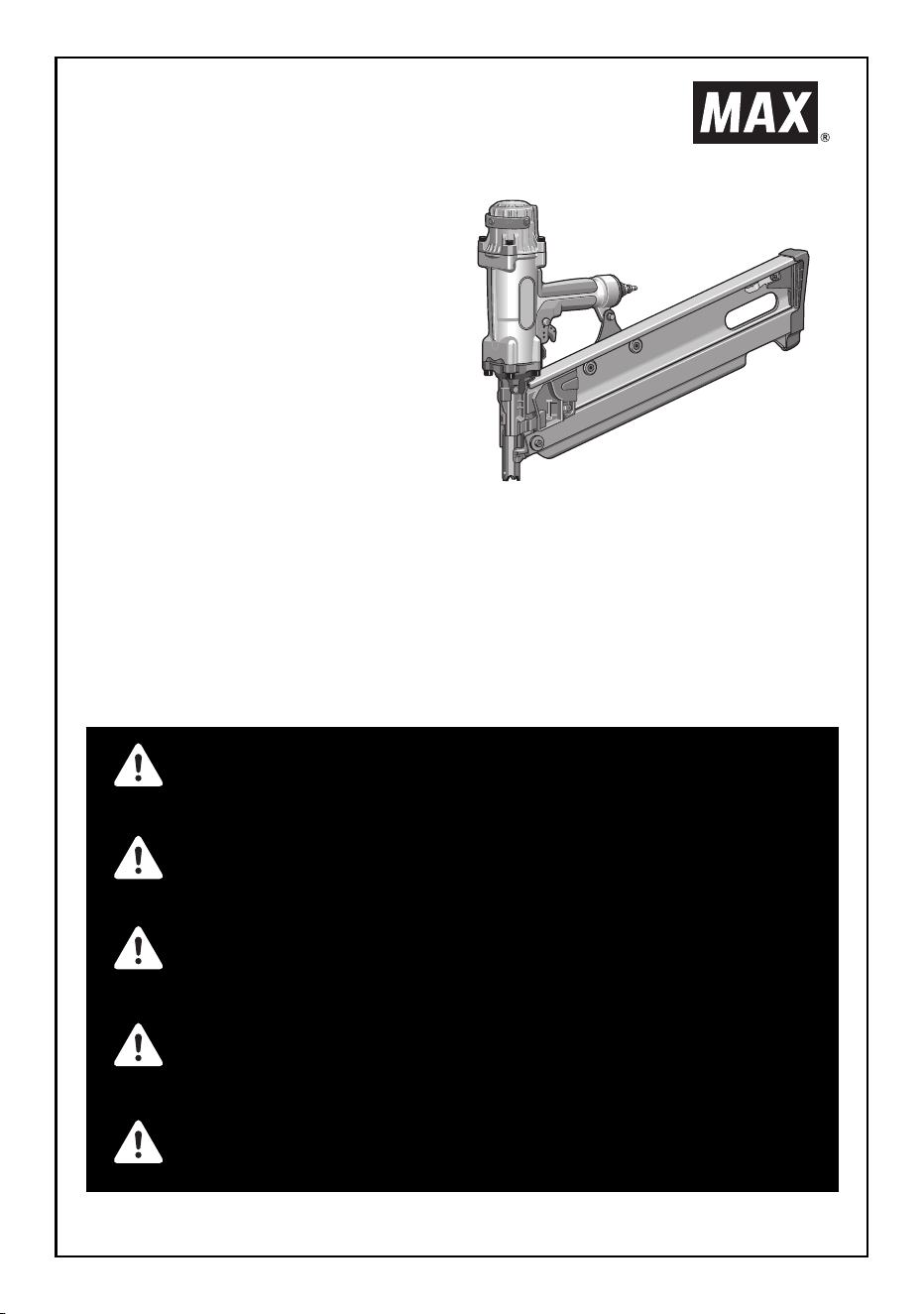
HS130(CE)
OPERATING and MAINTENANCE MANUAL
BETRIEBSANLEITUNG
MANUEL D'UTILISATION et D'ENTRETIEN
MANUALE DI FUNZIONAMENTO E MANUTENZIONE
MANUAL DE FUNCIONAMIENTO Y MANTENIMIENTO
HIGH PRESSURE FRAMING TOOL
HOCHDRUCK-STREIFENNAGLER
OUTIL D'ENCADREMENT À HAUTE PRESSION
ATTREZZO PER INCORNICIATURA AD ALTA
PRESSIONE
HERRAMIENTA DE ENMARCADO DE ALTA
PRESION
BEFORE USING THIS TOOL, STUDY THIS MANUAL TO ENSURE SAFETY WARNING
AND INSTRUCTIONS.
KEEP THESE INSTRUCTIONS WITH THE TOOL FOR FUTURE REFERENCE.
LESEN SIE VOR INBETRIEBNAHME DES GERÄTES DIE GEBRAUCHS- UND SICHER-
HEITSHINWEISE.BITTE BEWAHREN SIE DIE GEBRAUCHS- UND SICHERHEITSHIN-
WEISE AUF, DAMIT SIE AUCH SPÄTER EINGESEHEN WERDEN KÖNNEN.
AVANT D’UTILISER CET OUTIL, LIRE CE MANUEL ET LES CONSIGNES DE SECURITE
AFIN DE GARANTIR UN FONCTIONNEMENT SUR.
CONSERVER CE MANUEL EN LIEU SUR AVEC L’OUTIL AFIN DE POUVOIR LE
CONSULTER ULTERIEUREMENT.
PRIMA DI USARE QUESTA MACCHINA, STUDIARE IL MANUALE PER PRENDERE ATTO
DEGLI AVVERTIMENTI E DELLE ISTRUZIONIPER LA SICUREZZA.
TENERE QUESTE ISTRUZIONI INSIEME ALLO STRUMENTO PER CONSULTAZIONI FU-
TURE.
PARA EVITAR GRAVES DAÑOS PERSONALES O EN LA PROPIEDAD.
ANTES DE EMPLEAR LA HERRAMIENTA, LEER CON ADVERTENCIA Y COMPRENDER
LOS SIGUIENTES INSTRUCCIONES DE SEGURIDAD.
WARNING
WARNUNG
AVERTISSEMENT
ATTENZIONE
ADVERTENCIA

2
INDEX INHALTSVERZEICHNIS INDEX INDICE INDICE
ENGLISH Page 3 to 14
DEUTSCH Page 15 to 26
FRANÇAIS Page 27 to 38
ITALIANO Page 39 to 50
ESPAÑOL Page 51 to 62
PORTUGUÊS Consulte o CD-ROM ou o sítio web.
NEDERLANDS Raadpleeg de cd-rom of de website.
SVENSKA Se cd-skivan eller webbplatsen.
NORSK Referer til CD-ROMen eller til Web-sidene.
FINNISH Katso lisätietoja CD-ROM-levyltä tai verkkosivuilta.
DANSK Se cd-rom'en eller webstedet.
POLSKI
Więcej informacji na płycie CD-ROM lub stronie internetowej.
ΕΛΛΗΝΙΚΑ Ανατρέξτε στο CD-ROM ή στην τοποθεσία Web.
TÜRKÇE CD-ROM veya Web sitesine bakınız.
РУССКИЙ См. на компакт-диске или на веб-сайте.
DEFINITIONS OF SIGNAL WORDS
WARNING: Indicates a potentially hazardous situation which, if not avoided, could result in death or
serious injury.
CAUTION: Indicates a potentially hazardous situation which, if not avoided, may result in minor or
moderate injury.
NOTE: Emphasizes essential information.
DEFINITIONEN DER HINWEISBEZEICHNUNGEN
WARNUNG Zeigt eine eventuell gefährliche Situation an, die den Tod oder schwere Verletzungen zur
Folge haben könnte, wenn sie nicht vermieden wird.
VORSICHT! Zeigt eine eventuell gefährliche Situation an, die leichte oder mittelschwere Verletzungen
zur Folge haben könnte, wenn sie nicht vermieden wird.
HINWEIS: Hebt wichtige Informationen hervor.
DÉFINITIONS DES DIFFÉRENTS DEGRÉS D
AVERTISSEMENT Indique une situation éventuellement dangereuse qui, si elle n’est pas contournée, pour-
rait provoquer la mort ou des blessure sérieuses.
ATTENTION Indique une situation éventuellement dangereuse qui, si elle n’est pas contournée, pour-
rait provoquer des blessures légères à moyennement sérieuses.
REMARQUE Souligne des informations importantes.
DEFINIZIONE DELLE INDICAZIONI DI AVVERTIMENTO
ATTENZIONE: Indica l’eventualità che possa verificarsi una situazione pericolosa, la quale se non viene
evitata, può risultare letale o provocare gravi lesioni.
AVVERTENZA: Indica l’eventualità che possa verificarsi una situazione pericolosa, la quale se non viene
evitata, può provocare lesioni di lieve o media entità.
NOTA: Evidenzia informazioni importanti.
DEFINICIÓN DE LAS INDICACIONES DE ADVERTENCIA
ADVERTENCIA Indica una situación potencialmente peligrosa que podría causar la muerte o graves le-
siones si no se evita.
PRECAUCIÓN Indica una situación potencialmente peligrosa que podría causar lesiones menos graves
o leves si no se evita.
NOTA: Resalta informaciones importantes.
3
INDEX
1. SAFETY INSTRUCTIONS ..................................................3
2. SPECIFICATIONS AND TECHNICAL DATA ....................7
3. AIR SUPPLY AND CONNECTIONS ..................................8
4. INSTRUCTIONS FOR OPERATION ..................................9
5. MAINTENANCE................................................................14
6. STORAGE ........................................................................14
7. TROUBLE SHOOTING/REPAIRS....................................14
1. SAFETY INSTRUCTIONS
PRECAUTIONS ON USING THE TOOL
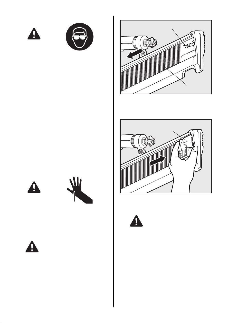
1. WEAR SAFETY GLASSES OR GOGGLES
Danger to the eyes always exists due to the
possibility of dust being blown up by the ex-
hausted air or of a fastener flying up due to
the improper handling of the tool. For these
reasons, safety glasses or goggles shall al-
ways be worn when operating the tool.
The employer and/or user must ensure that
proper eye protection is worn. Eye protection
equipment must conform to the require-
ments of Council Directive 89/686/EEC of 21
DEC. 1989 (the American National Stand-
ards Institute, ANSI Z87.1) and provide both
frontal and side protection.
The employer is responsible to enforce the
use of eye protection equipment by the tool
ENGLISH
OPERATING and MAINTENANCE MANUAL
BEFORE USING THIS TOOL, STUDY THIS MANUAL TO ENSURE SAFETY WARNING AND IN-
STRUCTIONS.
KEEP THESE INSTRUCTIONS WITH THE TOOL FOR FUTURE REFERENCE.
WARNING
TO AVOID SEVERE PERSONAL INJURY
OR PROPERTY DAMAGE
BEFORE USING THE TOOL, READ CARE-
FULLY AND UNDERSTAND THE FOLLOW-
ING "SAFETY INSTRUCTIONS". FAILURE
TO FOLLOW WARNINGS COULD RESULT
IN DEATH OR SERIOUS INJURY.
WARNING
4
operator and all other personnel in the work
area.
NOTE: Non-side shielded spectacles and
face shields alone do not provide adequate
protection.
2. EAR PROTECTION MAY BE REQUIRED
IN SOME ENVIRONMENTS
As the working condition may include expo-
sure to high noise levels which can lead to
hearing damage, the employer and user
should ensure that any necessary hearing
protection is provided and used by the oper-
ator and others in the work area.
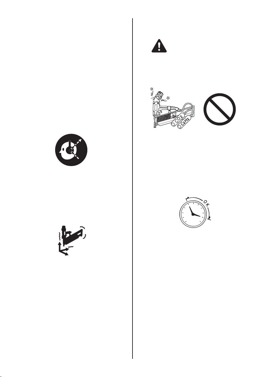
3. WHEN USING THE TOOL, BE SURE TO
USE A SPECIAL AIR COMPRESSOR AND
AIR HOSE
In order to improve its performance, it has
set its working pressure higher than the con-
ventional nailers. To use the tool, you always
need the special air compressor and air
hose. Use of combusible pressure gas (for
example, oxygen, acetylene, etc.) causes
abnormal combustion, possibly resulting in
explosion. Use only the special air compres-
sor and air hose.
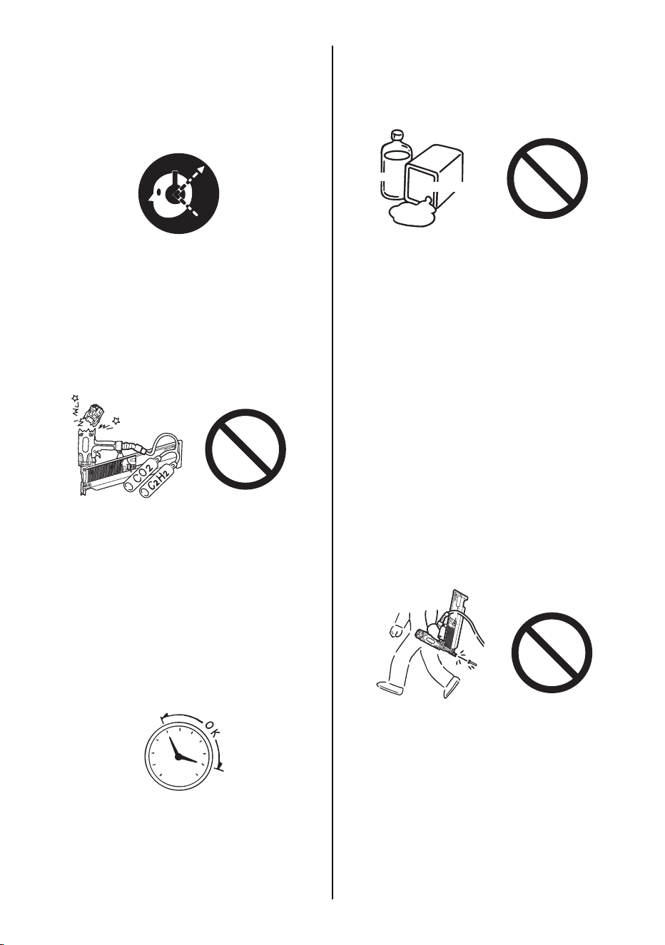
4. OPERATE WITHIN THE PROPER AIR
PRESSURE RANGE
The tool is designed to operate within an air
pressure range of 17 to 23 bar (250 to 320
p.s.i.).
The pressure should be adjusted to the type
of the work being fastened. The tool shall
never be operated when the operating pres-
sure exceeds 23 bar (320 p.s.i.).
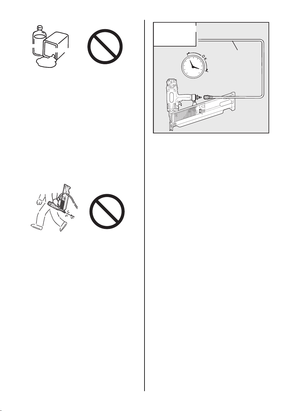
5. DO NOT OPERATE THE TOOL NEAR A
FLAMMABLE SUBSTANCE
Never operate the tool near a flammable
substance (e.g., thinner, gasoline, etc.). Vol-
atile fumes from these substances could be
drawn into the compressor and compressed
together with the air and this could result in
an explosion.
6. NEVER USE THE TOOL IN AN EXPLO-
SIVE ATMOSPHERE
Sparks from the tool may ignite atmospheric
gases, dust or other combustible materials.
7. DO NOT USE A WRONG FITTINGS
The connector on the tool must not hold
pressure when air supply is disconnected. If
a wrong fitting is used, the tool can remain
charged with air after disconnecting and thus
will be able to drive a fastener even after the
air line is disconnected, possibly causing in-
jury.
8. DISCONNECT THE AIR SUPPLY AND
EMPTY THE MAGAZINE WHEN THE
TOOL IS NOT IN USE
Always disconnect the air supply from the
tool and empty the magazine when operation
has been completed or suspended, when un-
attended, moving to a different work area, ad-
justing, disassembling, or repairing the tool,
and when clearing a jammed fastener.
17 bar
250 psi
23 bar
320 psi
Thinner
Gasoline
5
9. INSPECT SCREW TIGHTNESS
Loose or improperly installed screws or bolts
cause accidents and tool damage when the
tool is put into operation. Inspect to confirm
that all screws and bolts are tight and prop-
erly installed prior to operating the tool.
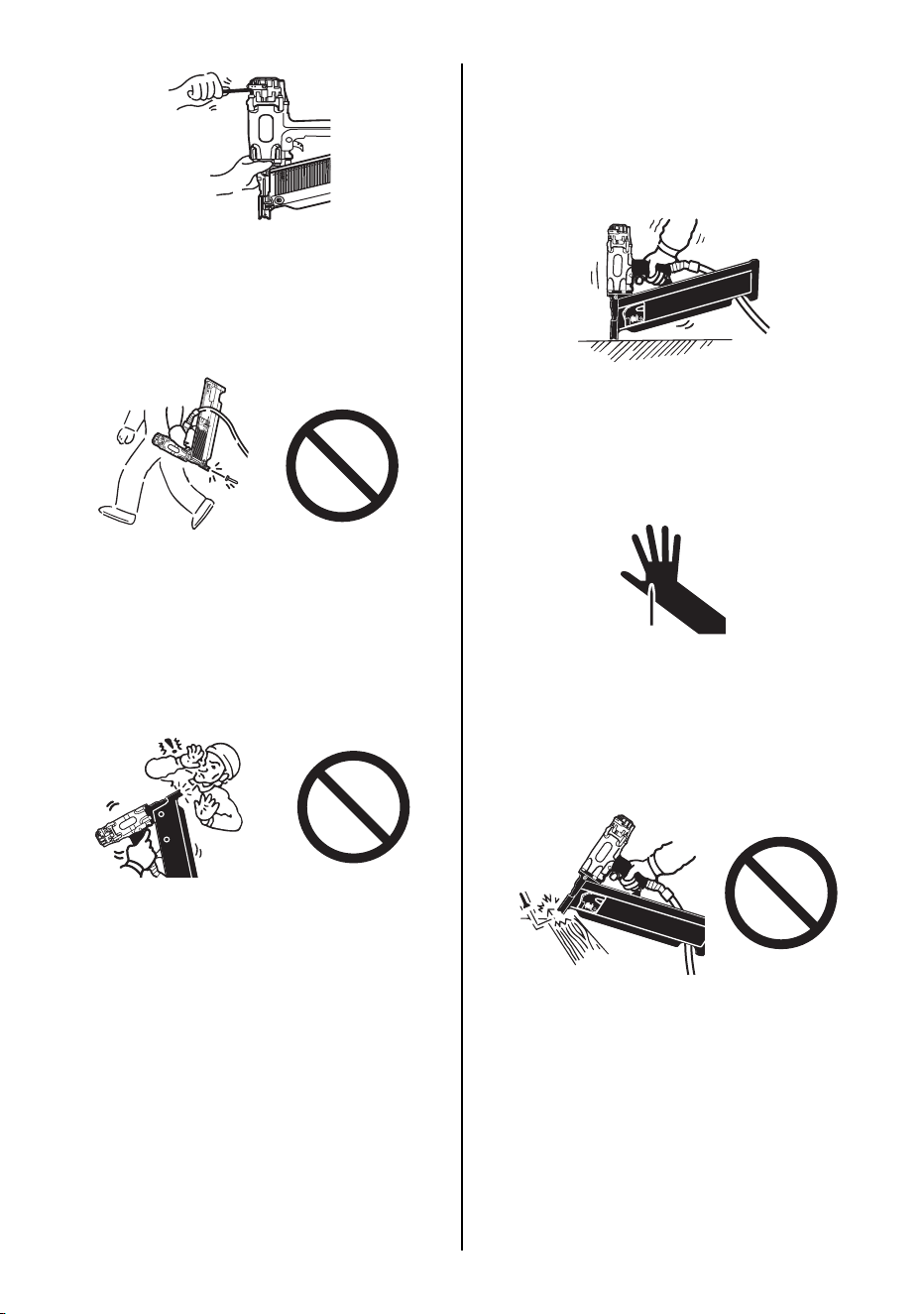
10. DO NOT TOUCH THE TRIGGER UNLESS
YOU INTEND TO DRIVE A FASTENER
Whenever the air supply is connected to the
tool, never touch the trigger unless you in-
tend to drive a fastener into the work. It is
dangerous to walk around carrying the tool
with the trigger pulled, and this and similar
actions should be avoided.
11. NEVER POINT THE DISCHARGE OUTLET
TOWARD YOURSELF AND OTHER PER-
SONNEL
If the discharge outlet is pointed toward peo-
ple, serious accidents may be caused when
misfiring. Be sure the discharge outlet is not
pointed toward people when connecting and
disconnecting the hose, loading and unload-
ing the fasteners or similar operations.
12. USE SPECIFIED FASTENERS
(SEE PAGE 7)
The use of fasteners other than specified
fasteners will cause the tool malfunction. Be
sure to use only specified fasteners when
operating the tool.
13. PLACE THE DISCHARGE OUTLET ON
THE WORK SURFACE PROPERLY
Failure to place the discharge outlet of the
nose in a proper manner can result in a fas-
tener flying up and is extremely dangerous.
14. KEEP HANDS AND BODY AWAY FROM
THE DISCHARGE OUTLET
When loading and using the tool, never
place a hand or any part of body in fastener
discharge area of the tool. It is very danger-
ous to hit the hands or body by mistake.
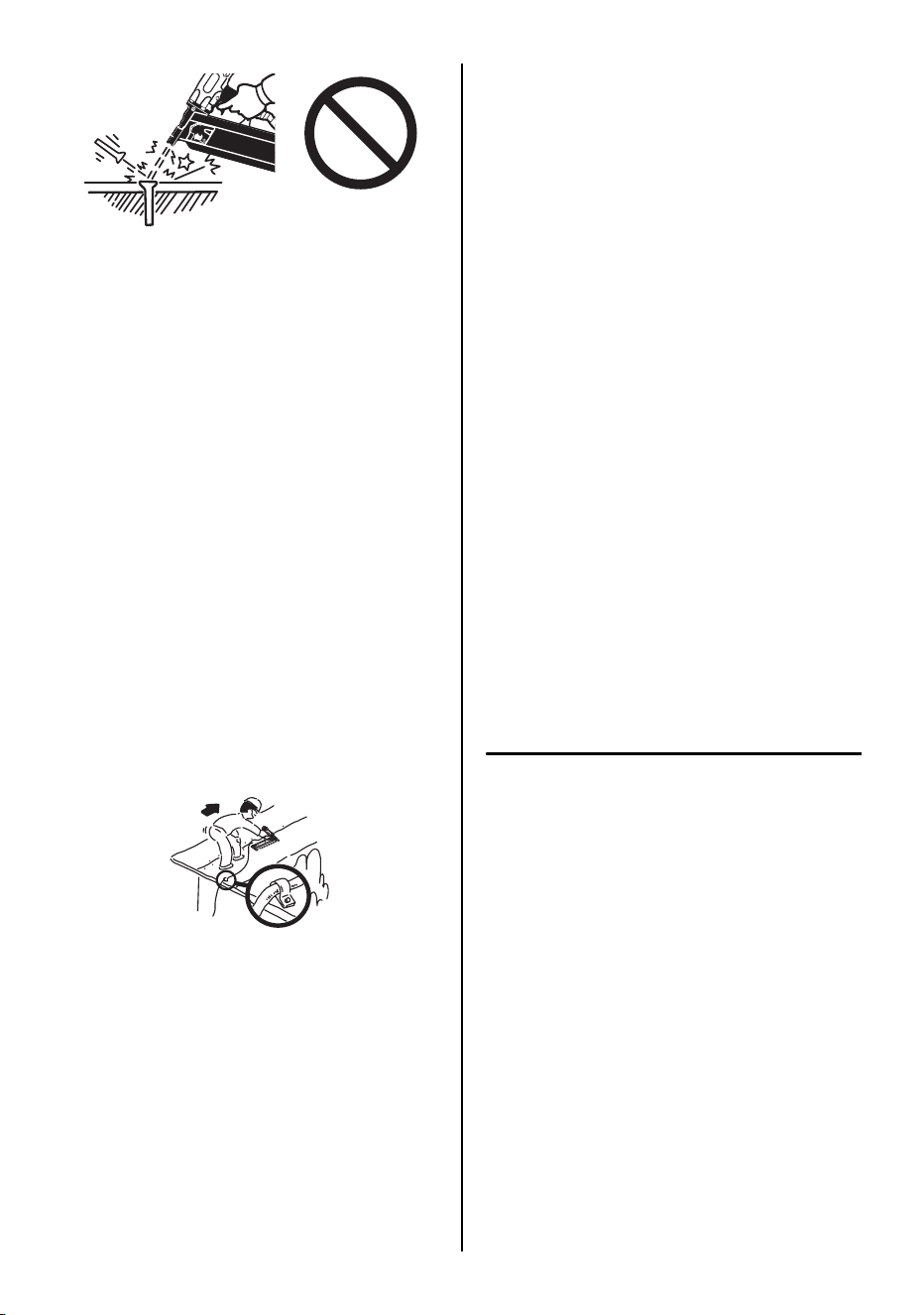
15. DO NOT DRIVE FASTENERS CLOSE TO
THE EDGE AND CORNER OF THE WORK
AND THIN MATERIAL
The workpiece is likely to split and the fas-
tener could fly free and hit someone.
6
16. DO NOT DRIVE FASTENERS ON TOP OF
OTHER FASTENERS
Driving fasteners on the top of other fasten-
ers may cause deflection fasteners which
could cause injury.
17. REMOVING THE FASTENERS AFTER
COMPLETING OPERATION
If fasteners are left in the magazine after the
completion of operation, there is the danger
of a serious accident occurring prior to the
resumption of operation, should the tool be
handled carelessly, or when connecting the
air fitting. For this reason, always remove all
fasteners remaining in the magazine after
completion of the operation.
18. CHECK OPERATION OF THE CONTACT
TRIP MECHANISM FREQUENTLY IN
CASE OF USING A CONTACT TRIP TYPE
TOOL
Do not use the tool if the trip is not working
correctly as accidental driving of a fastener
may result. Do not interfere with the proper
operation of the contact trip mechanism.
19. WHEN USING THE TOOL OUTSIDE OR
ELEVATED PLACE
When fastening roofs or similar slanted sur-
face, start fastening at the lower part and
gradually work your way up. Fastening back-
ward is dangerous as you may lose your foot
place.
Secure the hose at a point close to the area
you are going to drive fasteners. Accidents
may be caused due to the hose being pulled
inadvertently or getting caught.
20. NEVER USE THE TOOL IF ANY PORTION
OF THE TOOL CONTROLS (e.g., TRIG-
GER, CONTACT ARM) IS INOPERABLE,
DISCONNECTED, ALTERED OR NOT
WOKING PROPERLY
21. NEVER ACTUATE THE TOOL INTO FREE
SPACE
This will avoid any hazard caused by free fly-
ing fasteners and excessive strain of the
tool.
22. ALWAYS ASSUME THAT THE TOOL
CONTAINS FASTENERS
23. RESPECT THE TOOL AS A WORKING IM-
PLEMENT
24. NO HORSEPLAY
25. NEVER LOAD THE TOOL WITH FASTEN-
ERS WHEN ANY ONE OF THE OPERAT-
ING CONTROLS (e.g., TRIGGER,
CONTACT ARM) IS ACTIVATED
26. WEAR THE GLOVES DEPENDING ON
THE WORKING CONDITION
27. WHEN DISPOSING THE MACHINE OR ITS
PARTS, FOLLOW THE RELEVANT NA-
TIONAL RULES
OBSERVE THE FOLLOWING GENER-
AL CAUTION IN ADDITION TO THE
OTHER WARNINGS CONTAINED IN
THIS MANUAL
• Do not use the tool as a hammer.
• Always carry the tool by the grip, never car-
ry the tool by the air hose.
• The tool must be used only for the purpose
it was designed.
• Never remove, tamper with the operating
controls (e.g., TRIGGER, CONTACT ARM)
• Keep the tool in a dry place out of reach of
children when not in use.
• Do not use the tool without Safety Warning
label.
• Do not modify the tool from original design
or function without approval by MAX CO.,
LTD.
7
2. SPECIFICATIONS AND TECHNICAL DATA
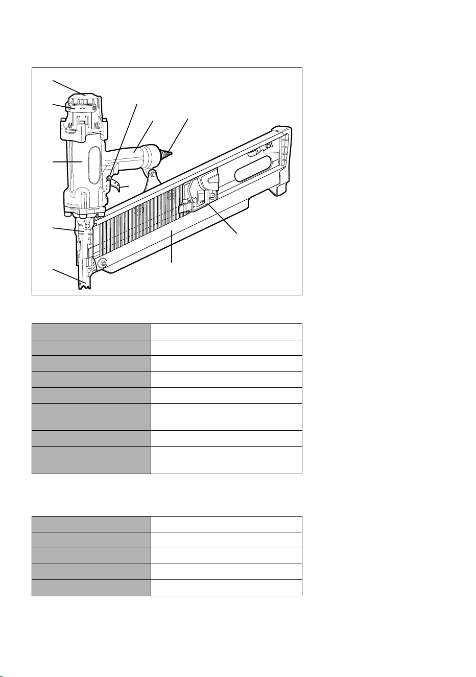
1. NAME OF PARTS
2. TOOL SPECIFICATIONS
* The compact design of the tool allows you to use in the narrow space.
3. FASTENER SPECIFICATIONS
1 Frame
2 Cylinder Cap
3 Contact Arm
4 Nose
5 Magazine
6 Trigger
7 Grip
8 Exhaust Cover
9 Pusher
0 Plug
a Trigger Lock Dial
PRODUCT NO. HS130
HEIGHT 426 mm (16-3/4")
WIDTH (Frame) 85 mm (3-3/8")
LENGTH 571 mm (22-1/2")
WEIGHT 4.3 kg (9.5 lbs.)
RECOMMENDED
OPERATING PRESSURE
17 to 23 bar (250 to 320 p.s.i.)
LOADING CAPACITY 60 Nails
AIR CONSUMPTION 5.4 l at 23 bar (320 p.s.i.)
operating pressure
PRODUCT NO. HS130
NAIL LENGTH 90 to 130 mm (3-1/2" to 5-1/8")
SHANK DIAMETER φ3.1 to φ4.2 mm (.122" to.165")
SHANK TYPE Smooth, Ring, Screw
HEAD DIAMETER φ7.0 to φ8.5 mm (.276" to .335")
1
4
3
8
2
ջ
9
7
0
5
6
8
RECOMMENDED OPERATING PRES-
SURE:
17 to 23 bar (250 to 320 p.s.i.). Select the oper-
ating air pressure within this range for best fas-
tener performance.
DO NOT EXCEED 23 bar (320 p.s.i.).
4. TECHNICAL DATA
1 NOISE
A-weighted single-event sound power level
------ LWA, 1s, d 101.5 dB
A-weighted single-event emission sound
pressure level at work station
------- LpA, 1s, d 92.0 dB
These values are determined and docu-
mented in accordance to EN12549 : 1999.
EAR PROTECTION MAY BE REQUIRED IN
SOME ENVIRONMENTS
As the working condition may include exposure to
high noise levels which can lead to hearing dam-
age, the employer and user should ensure that
any necessary hearing protection is provided and
used by the operator and others in the work area.
2 VIBRATION
Vibration characteristic value = 6.6 m/s
2
These values are determined and document-
ed in accordance to ISO 8662-11.
This value is a tool-related characteristic val-
ue and does not represent the influence to the
hand-arm-system when using the tool. An in-
fluence to the hand-arm-system when using
the tool will, for example, depend on the grip-
ping force, the contact pressure force, the
working direction, the adjustment of mains
supply, the workpiece, the workpiece support.
5. APPLICATIONS
∗ Roof, Floor and Wall framing
∗ Truss framing
3. AIR SUPPLY AND CON-
NECTIONS
Read section titled "SAFETY IN-
STRUCTIONS".
DO NOT USE ANY POWER SOURCE EXCEPT
AN AIR COMPRESSOR
The tool is designed to operate on compressed
air. Do not operate the tool on any other combus-
tible gases (e.g., oxygen, acetylene, etc.) since
there is the danger of an explosion. For this rea-
son, absolutely do not use anything other than
an air compressor to operate the tool.
OPERATE WITHIN THE PROPER AIR PRES-
SURE RANGE
The tool is designed to operate within an air
pressure range of 17 to 23 bar (250 to 320 p.s.i.).
The pressure should be adjusted to the type of
the work being fastened. The tool shall never be
operated when the operating pressure exceeds
23 bar (320 p.s.i.).
WARNING
17 bar
250 psi
23 bar
320 psi
9
DO NOT OPERATE THE TOOL NEAR A FLAM-
MABLE SUBSTANCE
Never operate the tool near a flammable sub-
stance (e.g., thinner, gasoline, etc.). Volatile
fumes from these substances could be drawn
into the compressor and compressed together
with the air and this could result in an explosion.
DO NOT USE A WRONG FITTINGS
The connector on the tool must not hold pressure
when air supply is disconnected. If a wrong fitting
is used, the tool can remain charged with air after
disconnecting and thus will be able to drive a fas-
tener even after the air line is disconnected, pos-
sibly causing injury.
DISCONNECT THE AIR SUPPLY AND EMPTY
THE MAGAZINE WHEN THE TOOL IS NOT IN
USE
Always disconnect the air supply from the tool
and empty the magazine when operation has
been completed or suspended, when unattend-
ed, moving to a different work area, adjusting,
disassembling, or repairing the tool, and when
clearing a jammed fastener.
WHEN USING THE TOOL, BE SURE TO USE A
SPECIAL AIR COMPRESSOR AND AIR HOSE.
In order to improve its performance, it has set its
working pressure higher than the conventional
nailers. To use the tool, you always need the
special air compressor and air hose (MAX Pow-
erLite Compressor and MAX PowerLite Hose).
Use of high-pressure gas (for example, oxygen,
acetylene, etc.) causes abnormal combustion,
possibly resulting in explosion. Use only the spe-
cial air compressor and air hose.
NOTE:
Frequent, but not excessive, lubrication is re-
quired for the best performance. Oil added thru
the air line connection will lubricate the internal
parts.
4. INSTRUCTIONS FOR OP-
ERATION
READ SECTION TITLED "SAFETY IN-
STRUCTIONS".
1. BEFORE OPERATION
Check the following prior operation.
1 Wear Safety Glasses or Goggles.
2 Do not connect the air supply.
3 Inspect screw tightness.
4 Check operation of the contact arm & trigger
if moving smoothly.
5 Connect the air supply.
6 Check the air-leakage. (The Tool must not
have the air-leakage.)
7 Hold the Tool with finger-off the trigger, then
push the contact arm against the work-piece.
(The tool must not operate.)
8 Hold the Tool with contact arm free from
work-piece and pull the trigger. (The Tool
must not operate.)
9 Disconnect the air supply.
Thinner
Gasoline
17 bar
250 psi
23 bar
320 psi
[AIR COMPRESSOR / AIR HOSE]
Air hose
Used at 17 to 23 bar
(250 to 320 p.s.i.)
Air compressor
10
2. OPERATION
Wear safety glasses or goggles. Danger to the
eyes always exists due to the possibility of dust
being blown up by the exhausted air or of a fas-
tener flying up due to the improper handling of
the tool. For these reasons, safety glasses or
goggles shall always be worn when operating
the tool.
The employer and/or user must ensure that
proper eye protection is worn. Eye protection
equipment must conform to the requirements of
Council Directive 89/686/EEC of 21 DEC. 1989
(the American National Standards Institute,
ANSI Z87.1) and provide both frontal and side
protection.
The employer is responsible to enforce the use
of eye protection equipment by the tool operator
and all other personnel in the work area.
NOTE:
Non-side shielded spectacles and face
shields alone do not provide adequate protection.
Keep hands and body away from the discharge
outlet when driving the fasteners because of
dangerous of hitting the hands or body by mis-
take.
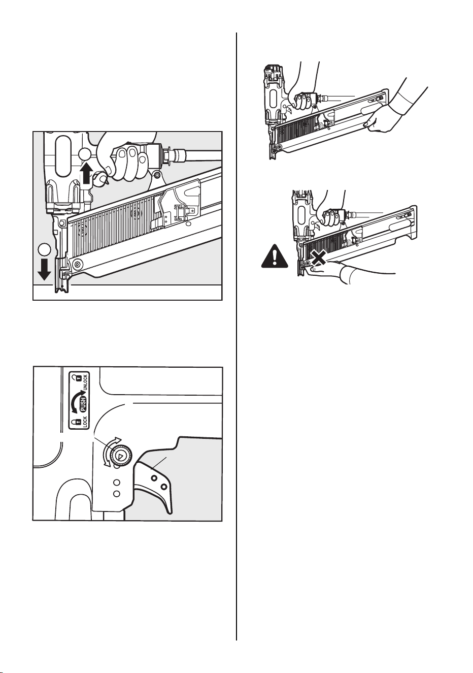
NAIL LOADING
•
When loading the nails, be sure to release
the finger from the Trigger.
•
Do not press the Contact Arm against the
object.
PROCEDURE
1 Load the nails into the slot in the rear of the
Magazine until they go over the Nail Stopper.
2 Pull the Pusher as far as the rear end of the
magazine and release it gently.
Abrupt release of the Pusher causes jamming
of nails or dry-firing.
TEST OPERATION
1 Adjust the air pressure at 17 bar (250 p.s.i.)
and connect the air supply.
2 Without touching the trigger, depress the
contact arm against the work-piece.
Pull the trigger. (The tool must fire the fas-
tener.)
3 With the tool off the work-piece, pull the trig-
ger.
WARNING
WARNING
WARNING
Nail Stopper
Nails
Pusher
CAUTION
11
Then depress the contact arm against the
work-piece. (The tool must fire the fastener.)
4 Adjust the air pressure as much as the low-
est possible according the length of fastener
and the hardness of work-piece.
MODEL IDENTIFICATION
SEQUENTIAL TRIP
The Sequential Trip requires the operator to hold
the tool against the work before pulling the trig-
ger. This makes accurate fastener placement
easier, for instance on framing, toe nailing and
crating applications. The Sequential Trip allows
exact fastener location without the possibility of
driving a second fastener on recoil, as described
under "Contact Trip".
The Sequential Trip Tool has a positive safety
advantage because it will not accidentally drive a
fastener if the tool is contacted against the work-
or anything else-while the operator is holding the
trigger pulled.
SEQUENTIAL TRIP
Identified by ORANGE TRIGGER.
12
DRIVING FASTENERS
SINGLE FIRE OPERATION
(SEQUENTIAL TRIP)
For single fire operation, depress the contact
arm against the work surface and pull the trigger.
Tool can not fire a second fastener until the trig-
ger is released and tool can cycle.
PROCEDURE
1 Depress the contact arm.
2 Pull the trigger.
TRIGGER LOCK MECHANISM
The tool is equipped with a trigger lock mecha-
nism. Push and rotate the trigger LOCK to the
trigger UNLOCK position before driving nails.
DRIVING FASTENERS
When using the tool with both hands;
Hold the rear of the magazine to use.
Do not hold the front of the magazine because
your hand may be injured by nails.
1
2
Trigger lock dial
(UNLOCK)
(LOCK)
Trigger
WARNING
13
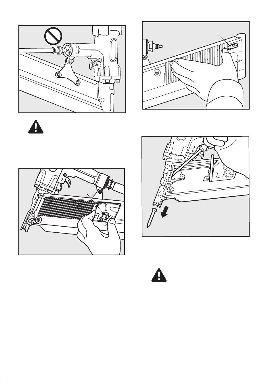
REMOVING JAMMED NAILS
ALWAYS disconnect air supply before remov-
ing jammed nails.
PROCEDURE
1 Push the Pusher Lever and release the strip
nails from the Pusher.
2 Push the Nail Stopper, and remove the strip
nails from inside of the Magazine.
3 Pull and stayed the Pusher with hand.
4 Remove the jammed nail from the Nose us-
ing a punch or a slotted screw driver.
When removing the jammed nail, wear the
gloves.
Do not remove the jammed nail with your bare
hands.
WARNING
Pusher Lever
Nail Stopper
WARNING
14
5. MAINTENANCE
1 ABOUT PRODUCTION YEAR
This product bears production number at the
lower part of the grip of the main body. The
two digits of the number from left indicates
the production year.
2 DO NOT FIRE THE NAILER WHEN IT IS
EMPTY
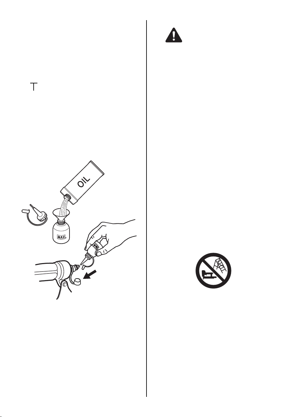
3 USE RECOMMENDED OIL
The velocite or turbine oil should be used to
lubricate the tool. Upon completion of opera-
tions, place 5 or 6 drops of oil into the air plug
inlet with the jet oiler. (Recommended Oil :
ISO VG32)
4 INSPECT AND MAINTAIN DAILY OR BE-
FORE OPERATION
Disconnect air supply and empty the maga-
zine when inspecting or maintaining the tool.
(1) Tighten all screws
(2) Keep contact arm moving smoothly
6. STORAGE
1 When not in use for an extended period, ap-
ply a thin coat of the lubricant to the steel
parts to avoid rust.
2 Do not store the tool in a cold weather envi-
ronment. Keep the tool in a warm area.
3 When not in use, the tool should be stored in
a warm and dry place. Keep out of reach of
children.
4 All quality tools will eventually require servic-
ing or replacement of parts because of wear
from the normal use.
7. TROUBLE SHOOTING/RE-
PAIRS
The troubleshooting and/or repairs shall be car-
ried out only by the MAX CO., LTD. authorised
distributors or by other specialists.
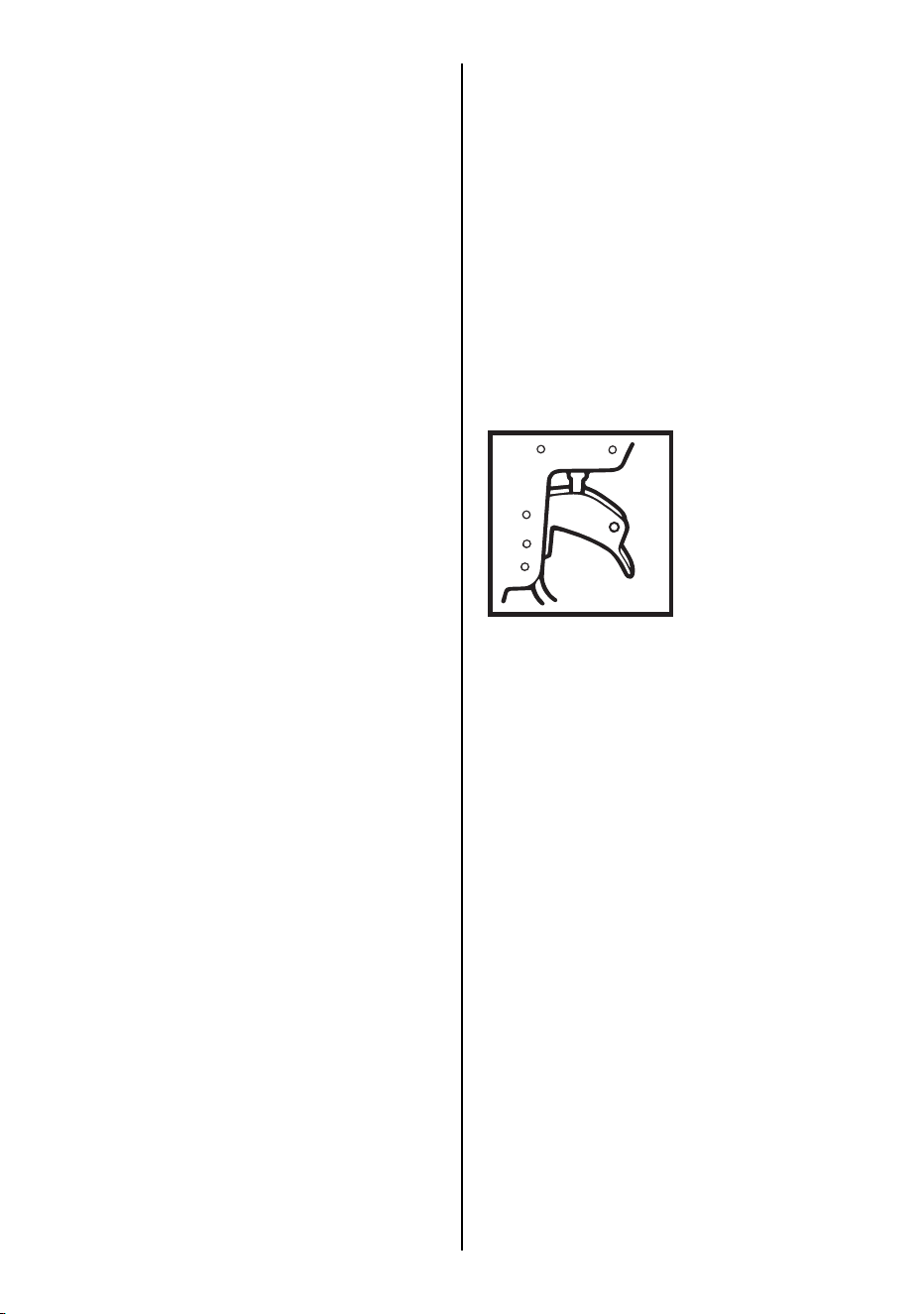
Supplement to the operating instruction
According to the European Norm EN 792-13 the
regulation is valid from 01.01.2001 that all fas-
tener driving tools with contact actuation must be
marked with the symbol "Do not use on scaffold-
ings, ladders" and they shall not be used for spe-
cific application for example:
∗ when changing one driving location to another
involves the use of scaffoldings, stairs, ladders
or ladder alike constructions e.g. roof laths,
∗ closing boxes or crates,
∗ fitting transportation safety systems e.g. on ve-
hicles and wagons.
(Example)
0 8 8 2 6 0 3 5 D
Year 2008
WARNING