
Induction
Cooktop System
Installation
Manual

2 | Tulip Cooking Induction Cooktop System Installation Manual
Before installing and using your Tulip Cooking induction
cooktop, read this manual carefully for your own safety and
to prevent damage to the cooktop unit and/or your kitchen.
IMPORTANT: This unit is for residential use only.
Installation and connection must be done by a
licensed technician. The manufacturer will not be held
responsible for any damage caused by errors in installation
or connection.
The unit must be installed in a suitable countertop material.
In order to accommodate service for your Tulip Cooking
induction cooktop, the area above the cooktop (e.g., upper
cabinets) and below (e.g., base cabinet and drawers) must
remain freely accessible in accordance with the full width
and depth of the cooktop unit. The cooktop must be
removable from both underneath and in front.
Table of Contents
Unit Dimensions 3
Multizone Installation Requirements 4
Connection of Cooking Zones 5
Configuring the Cooktop Unit 6
Electrical Connection Requirements 7
Connecting the Cooktop Unit 7
Tulip Cooking Induction Cooktop System Installation Manual | 3
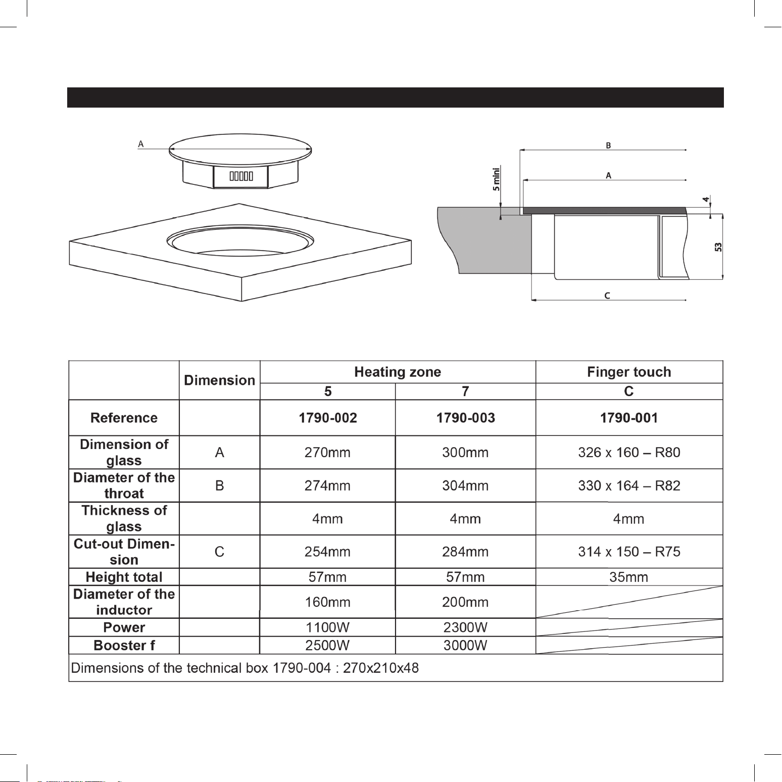
Unit Dimensions
4 | Tulip Cooking Induction Cooktop System Installation Manual
Multizone Installation Requirements
IMPORTANT: Installation and connection must be done
by a licensed technician. The technician must follow local
codes and regulations for installation and safety.
Prior to installation, unpack all of the materials, and remove
all labels and self-adhesives from the ceramic glass.
Do not modify the unit, as this will void the product warranty.
Neither the cooking zones nor the control panel should be used
as a support surface or a worktop.
The unit must be grounded and connected to conform
to local code.
Do not use an extension cable when connecting the unit.
The unit must not be installed above a dishwasher or a tumble-
dryer, as the steam may damage the electronic components.
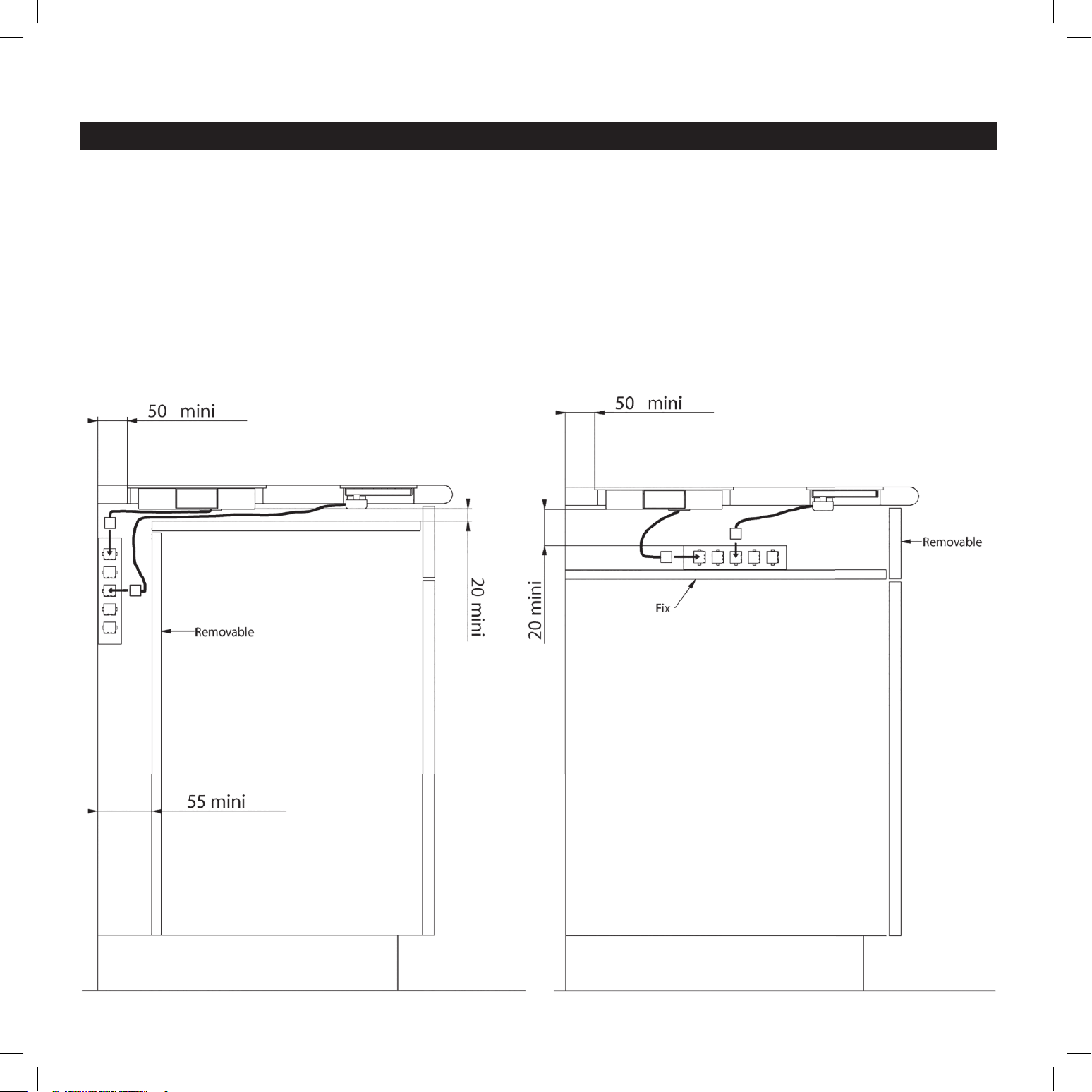
IMPORTANT: A gap of at least 20mm must be established in
front of the cooling fan’s air inlet, as the cooling system requires
airfl ow for ventilation. (See diagram below.)
Tulip Cooking Induction Cooktop System Installation Manual | 5
Multizone Installation Requirements (continued)
Tulip Cooking induction cooktops are classifi ed as “Y” class for
heat protection. The countertop surface, the countertop edges,
the laminate coatings, and the glue used to affi x the cooktop
must be able to withstand temperatures of up to 212˚F (100˚C).
It is acceptable to install the cooktop unit in a countertop that
is positioned lengthwise against a wall. It is also acceptable
to have a tall appliance or wall positioned next to one of the
countertop’s short sides; however, on the opposite side, no
appliance or wall may stand higher than the countertop.
In all cases, the cooktop must be installed with a minimum
distance of 2” (50mm) from all sides of the unit to any wall or
appliance. See diagram on page 4.
To protect the edges of the countertop cut-outs, your
countertop fabricator must seal the countertop once it is cut.
Care must be taken when applying the adhesive joint supplied
with the unit to prevent any leakage into the countertop. This
gasket ensures a correct seal when used in conjunction with a
smooth countertop surface.
A hood should be installed in conjunction with the cooktop.
Please check with your local municipality for proper codes
and regulations.
After installation, the connection cords should be free from
obstruction, with no mechanical constraint or twisting.
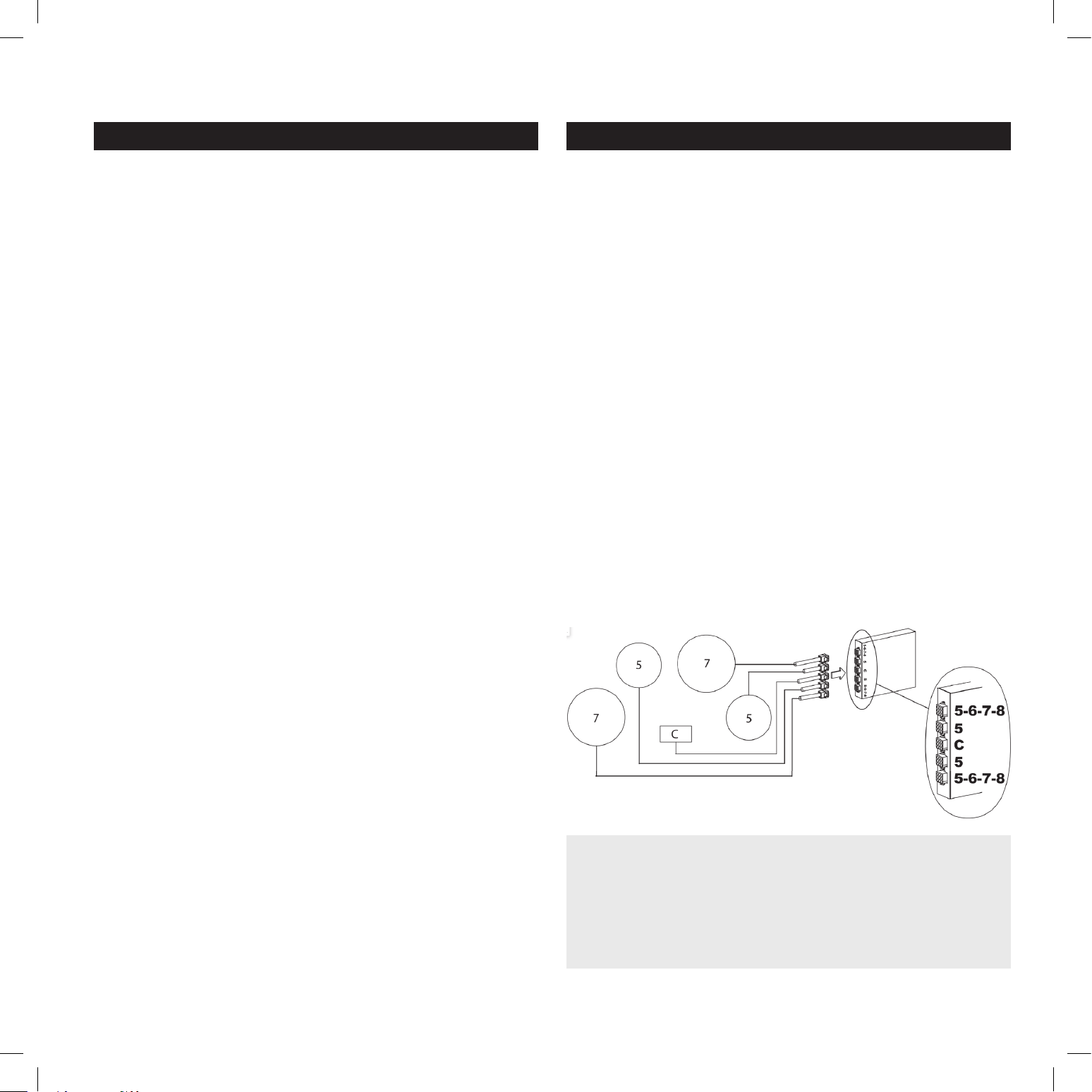
Connection of Cooking Zones
IMPORTANT: Connection to the electrical network should
be done by a licensed electrician.
The connectors for the cooking zones are identifi ed by stickers
with classifi cations from 5 to 8:
5 – Heating Zone 1100 W / Glass diameter 270mm
7 – Heating Zone 2300 W / Glass diameter 300mm
The touchpad electronic control panel is identifi ed by “C” on the
connector.
On the technical box, near the female connectors, are the labels
5-6-7-8-C.
Connect the touchpad electronic control panel to the “C” port
on the technical box.
Connect each heating zone to its corresponding numbered
port on the technical box. For easiest connection, start with
the highest numbered heating zone, and continue in reverse
numeric order to the lowest number.
Example:
IMPORTANT: Do not lengthen or shorten the wire
for any cooking zone, as this will void the product
warranty. Tulip Cooking will not be held responsible
for any damage, malfunction, or hazard caused by
a wiring change done by the customer.
6 | Tulip Cooking Induction Cooktop System Installation Manual
Confi guring the Cooktop Unit
IMPORTANT: Before starting the confi guration process,
ensure there are no pots sitting on the cooktop.
Please note that during the confi guration process, the control
panel will be completely dark (unlit). A fl ashlight may be
required for clear viewing of panel information.
Step 1: Prepare the unit for confi guration.
a. Select and set aside a pot with a ferromagnetic bottom and
a minimum diameter of 6.3” (16cm). Be sure to fi ll the pot
partially with water; it is a safety hazard to heat an empty pot.
b. Disconnect the unit from the electrical supply by removing
the fuse or turning off the circuit breaker.
c. Reconnect to the electrical supply.
d. Start the confi guration procedure within 2 minutes after
reconnecting the unit.
e. Do not use the on/off button [ O/I ] on the control panel
during the confi guration process.
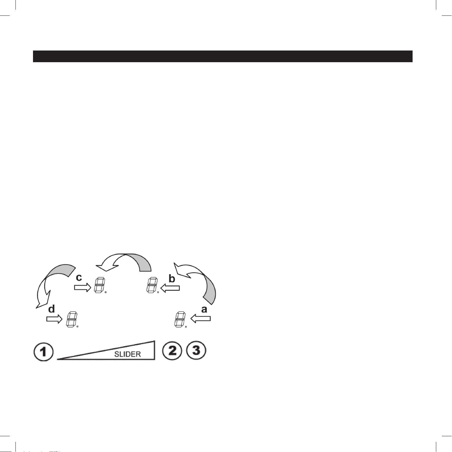
Step 2: Cancel the default confi guration.
a. Press and hold button 2. The symbol [ – ] will appear on
each display.
b. With your other hand, press quickly and successively (less
than 2 seconds) on each [ – ] display. Begin at the front right
and continue counterclockwise, as shown in the diagram
below left (a > b > c > d). If you hear a double “beep” sound,
an error has occurred and you must start the process again
from the beginning. (See Step 1.)
c. Remove your fi ngers from the touch control, then press and
hold button 1 for a few seconds, until blinking [ E ] symbols
appear.
d. Wait until [ E ] symbols stop blinking. After few seconds, the
[ E ] symbol changes to [ C ], which means the existing setup
has been cancelled.
Step 3: Create a new setup.
a. Select a cooking zone by pressing the corresponding
[ C ] display.
b. Place a pot on the zone to be set; the pot must be fi lled partially
with water, and must have a ferromagnetic bottom and a
minimum diameter of 6.3” (16cm). Be sure to use the same pot
for the entire process, moving it from zone to zone. Never place
several pots together on the zones during the setup process.
c. Wait until the [ C ] display changes to [ – ]. The selected
cooking zone is now confi gured.
d. Follow the same procedure for each cooking zone using
the [ C ] displays.
e. Once all the displays have turned off , all cooking zones have
been confi gured.
If you see an error symbol [ E4 ], reconfi gure the control unit.
If the error symbol persists, please contact Tulip Cooking at
www.tulipcooking.com/service.
Tulip Cooking Induction Cooktop System Installation Manual | 7
Electrical Connection Requirements
IMPORTANT: Connection to the electrical network should
be done only by a licensed electrician.
Protection for parts under tension must be ensured after
installation.
Connection instructions are found on the stickers placed on the
unit casing near the connection box.
Connection to the main must be made using a grounded plug
or via an omnipolar circuit breaking device with a contact
opening of at least 0.12” (3mm).
The electrical circuit must be separated from the network by
adapted devices, e.g., circuit breakers, fuses, or contactors.
Connecting the Cooktop Unit
For the various types of connections, use the brass bridges
found in the box next to the terminal.
CAUTION: Always connect
to a grounded wire.
Refer to the connection specifications at the top right of this page.
This device is intended for a supply of 230 V ~ 60Hz.
The connection box is located underneath the unit casing at
the rear. To open the cover, use a medium standard screwdriver.
Place it in the slots and open the cover.
Country: USA, Canada
Mains: 230V~1P+N 60Hz
Connection: 1 Phase + N
Cable Diameter: 3 x 2.5mm
2
Cable: H 05 VV - F / H 05 RR - F
Protection caliber: 30 A
IMPORTANT: Do not extend or shorten any wire for the cooking
zones (5/6/7/8); see page 5 for details. Only the wire for the
control panel (C) may be extended. For more information,
please contact Tulip Cooking.
Monophase 230V~1P+N: Place the first bridge between
terminal 1 and 2, and the second between 3 and 4. Attach the
ground to the Earth terminal (globe symbol), the neutral N to
terminal 3 or 4, and the Phase L to either terminal 1 or 2.
CAUTION: Be sure that cables are properly
engaged and tightened. Tulip Cooking will
not be held responsible for any damage,
malfunction, or hazard resulting from incorrect
connection or which could arise from the use of a unit
that has not been grounded properly or has been
equipped with a faulty ground connection.

USA
Tulip Cooking
209 River Road Extension
Cos Cob, CT 06807
203-900-1124
Canada
Better Distribution
111 Oakdale Road
North York, ON M3N 1W2
905-264-9414
www.tulipcooking.com