®®
Visit our website at: https://www.harborfreight.com
email our technical support at: [email protected]
9 GALLON
WHEELBARROW AIR
COMPRESSOR
Owner’s Manual & Safety Instructions
Save This Manual Keep this manual for the safety warnings and precautions, assembly,
operating, inspection, maintenance and cleaning procedures. Write the product’s Date Code in the back of
the manual (or month and year of purchase if product has no number). Keep this manual and the receipt in
a safe and dry place for future reference. 25d
When unpacking, make sure that the product is intact
and undamaged. If any parts are missing or broken,
please call 1‑800‑444‑3353 as soon as possible.
Copyright
©
2024 by Harbor Freight Tools
®
. All rights reserved.
No portion of this manual or any artwork contained herein may be reproduced in
any shape or form without the express written consent of Harbor Freight Tools.
Diagrams within this manual may not be drawn proportionally. Due to continuing
improvements, actual product may differ slightly from the product described herein.
Tools required for assembly and service may not be included.
read this material before using this product.
Failure to do so can result in serious injury.
SaVe tHiS ManUal.
HIGH PERFORMANCE
SERIES
AIR COMPRESSOR
Using an engine indoors
can Kill yOU in MinUteS.
engine exhaust contains carbon monoxide.
this is a poison you cannot see or smell.
neVer use inside
a home or garage,
eVen iF doors and
windows are open.
Only use OUtSiDe
and far away from
windows, doors,
and vents.
Page 2 For technical questions, please call 1-800-444-3353. Item 70734
SaFety OperatiOn MaintenanceinStallatiOn
table of contents
Safety ........................................................................2
Installation .................................................................2
Specifications ............................................................7
Operation .................................................................. 10
Maintenance .............................................................14
Parts List and Diagram .............................................18
Warranty ...................................................................20
WarninG SyMBOlS anD DeFinitiOnS
This is the safety alert symbol. It is used to alert you to potential
personal injury hazards. Obey all safety messages that
follow this symbol to avoid possible injury or death.
Indicates a hazardous situation which, if not avoided,
will result in death or serious injury.
Indicates a hazardous situation which, if not avoided,
could result in death or serious injury.
Indicates a hazardous situation which, if not avoided,
could result in minor or moderate injury.
Addresses practices not related to personal injury.
®®

Page 3For technical questions, please call 1-800-444-3353.Item 70734
SaFetyOperatiOnMaintenance inStallatiOn
iMpOrtant SaFety inFOrMatiOn
General Safety Warnings
WarninG read all safety warnings and instructions.
Failure to follow the warnings and instructions may result in electric shock, fire and/or serious injury.
Save all warnings and instructions for future reference.
The warnings, precautions, and instructions discussed in this instruction manual cannot cover all possible
conditions and situations that may occur. It must be understood by the operator that common sense
and caution are factors which cannot be built into this product, but must be supplied by the operator.
Set Up precautions
1. Keep work area clean and well lit.
Cluttered or dark areas invite accidents.
2. Do not operate the compressor
in explosive atmospheres, such
as in the presence of flammable
liquids, gases or dust. Gasoline‑powered
engines may ignite the dust or fumes.
3. Keep children and bystanders away
from an operating compressor.
4. Gasoline fuel and fumes are flammable, and
potentially explosive. Use proper fuel storage
and handling procedures. Do not store fuel
or other flammable materials nearby.
5. Have multiple ABC class fire extinguishers nearby.
6. Operation of this equipment may create sparks
that can start fires around dry vegetation. A spark
arrestor may be required. The operator should
contact local fire agencies for laws or regulations
relating to fire prevention requirements.
7. Set up and use only on a flat, level,
well‑ventilated surface.
8. Use only lubricants and fuel recommended
in the engine manual or in the
Specifications chart of this manual.
9. Wear ANSI‑approved safety glasses, hearing
protection, and NIOSH‑approved dust mask/
respirator under a full face shield along
with steel‑toed work boots during use.
10. Do not overreach. Keep proper footing and
balance at all times. This enables better control
of the equipment in unexpected situations.
11. Dress properly. Do not wear loose clothing or
jewelry. Keep hair, clothing and gloves away
from moving parts. Loose clothes, jewelry or
long hair can be caught in moving parts.
engine precautions
Follow engine precautions and instructions in the included engine instruction manual.
personal Safety
1. Stay alert, watch what you are doing and
use common sense when operating this
compressor. Do not use this compressor
while you are tired or under the influence
of drugs, alcohol or medication. A moment
of inattention while operating a compressor
may result in serious personal injury.
2. Use personal protective equipment.
always wear anSi-approved eye
protection during setup and use.
3. prevent unintentional starting.
ensure the switch is in the off-position
before moving the compressor.
Page 4 For technical questions, please call 1-800-444-3353. Item 70734
SaFety OperatiOn MaintenanceinStallatiOn
Operating precautions
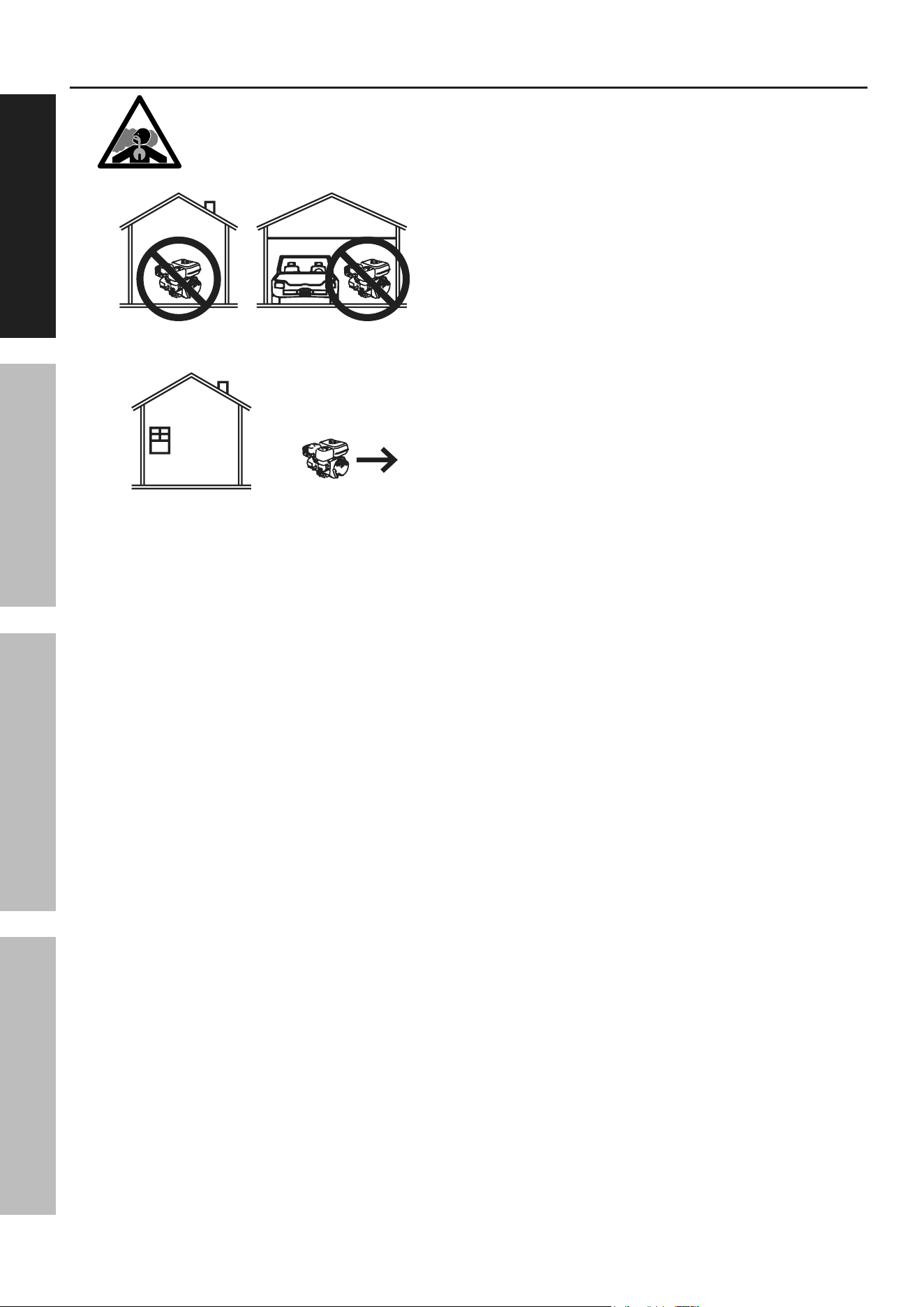
1. carBOn MOnOXiDe HaZarD
Using an engine indoors can Kill
yOU in MinUteS.
Engine exhaust contains carbon
monoxide. This is a poison you cannot see or smell.
NEVER use inside a home or garage, EVEN IF
doors and windows are open.
Only use OUTSIDE and far away from windows,
doors, and vents.
2. Keep children away from the equipment,
especially while it is operating.
3. Fire Hazard! Do not fill gas tank while Compressor
engine is running. Do not operate if gasoline has
been spilled. Clean spilled gasoline before starting
engine. Do not operate near pilot light or open flame.
4. Do not touch Compressor engine during
use. Let engine cool down after use.
a. Do not use the compressor if the switch
does not turn it on and off. Any compressor
that cannot be controlled with the switch
is dangerous and must be repaired.
b. Store an idle compressor out of the reach
of children and do not allow persons
unfamiliar with the compressor or these
instructions to operate it. A compressor is
dangerous in the hands of untrained users.
5. Never store fuel or other flammable
materials near the Compressor engine.
6. Only use a suitable means of transport and
lifting devices with sufficient weight bearing
capacity when transporting the Compressor.
7. Secure the Compressor on transport vehicles to
prevent the tool from rolling, slipping, and tilting.
8. Use only accessories that are recommended
by Harbor Freight Tools for your model.
Accessories that may be suitable for one
piece of equipment may become hazardous
when used on another piece of equipment.
9. Parts, especially exhaust system components,
get very hot during use. Stay clear of hot parts.
10. Do not cover the engine or
equipment during operation.
11. Maintain the compressor. Keep the compressor
clean for better and safer performance. Follow
instructions for lubricating and changing
accessories. Keep dry, clean and free from
oil and grease. check for misalignment or
binding of moving parts, breakage of parts
and any other condition that may affect the
compressor’s operation. if damaged, have the
compressor repaired before use. Many accidents
are caused by a poorly maintained compressor.
12. Use the compressor in accordance with these
instructions, taking into account the working
conditions and the work to be performed. Use of
the compressor for operations different from those
intended could result in a hazardous situation.
13. Do not operate the equipment with known
leaks in the engine’s fuel system.
14. When spills of fuel or oil occur, they must be
cleaned up immediately. Dispose of fluids and
cleaning materials as per any local, state, or
federal codes and regulations. Store oil rags in
a bottom‑ventilated, covered, metal container.
15. Keep hands and feet away from moving parts. Do
not reach over or across equipment while operating.
16. Before use, check for misalignment or binding
of moving parts, breakage of parts, and any
other condition that may affect the equipment’s
operation. if damaged, have the equipment
serviced before using. Many accidents are
caused by poorly maintained equipment.
17. Use the correct equipment for the application.
Do not modify the equipment and do not use the
equipment for a purpose for which it is not intended.

Page 5For technical questions, please call 1-800-444-3353.Item 70734
SaFetyOperatiOnMaintenance inStallatiOn
Service precautions
Have your compressor serviced by a qualified repair person using only identical
replacement parts. this will ensure that the safety of the compressor is maintained.
1. Before service, maintenance, or cleaning:
a. turn the engine switch to its “OFF” position.
b. allow the engine to completely cool.
c. then, remove the spark plug
cap from the spark plug.
2. Keep all safety guards in place and in
proper working order. Safety guards include
muffler, air cleaner, mechanical guards,
and heat shields, among other guards.
3. Do not alter or adjust any part of the
equipment or its engine that is sealed by the
manufacturer or distributor. Only a qualified
service technician may adjust parts that may
increase or decrease governed engine speed.
4. Wear ANSI‑approved safety goggles,
heavy‑duty work gloves, and dust
mask/respirator during service.
5. Maintain labels and nameplates on
the equipment. These carry important
information. If unreadable or missing, contact
Harbor Freight Tools for a replacement.
6. Store equipment out of the reach of children.
7. Follow scheduled engine and
equipment maintenance.
air compressor Safety Warnings
1. risk of fire or explosion - do not spray
flammable liquid in a confined area or towards a
hot surface. Spray area must be well-ventilated.
Do not smoke while spraying or spray where
spark or flame is present. arcing parts - keep
compressor at least 20 feet away from explosive
vapors, such as when spraying with a spray gun.
2. risk of bursting - do not adjust regulator higher
than marked maximum pressure of attachment.
3. risk of injury - do not direct air
stream at people or animals.
4. Do not use to supply breathing air.
5. Keep compressor well-ventilated.
Do not cover compressor during use.
6. add correct amount of compressor oil before
first use and every use. Operating with the
incorrect amount of oil causes permanent
damage and voids warranty. to prevent
damage, do not use with overfilled or low oil.
7. Drain Tank daily and after use.
Internal corrosion causes tank failure and explosion.
8. Do not remove the valve cover or
adjust internal components.
9. Compressor head gets hot during operation.
Do not touch it or allow children nearby
during or immediately following operation.
10. Do not use the air hose to move the compressor.
11. Release the pressure in the
storage tank before moving.
12. The use of accessories or attachments not
recommended by the manufacturer may
result in a risk of injury to persons.
13. All air line components, including hoses, pipe,
connectors, filters, etc., must be rated for a minimum
working pressure of 175 PSI, or 150% of the
maximum system pressure, whichever is greater.
14. Industrial applications must follow OSHA guidelines.
15. Maintain labels and nameplates on the
compressor. These carry important safety
information. If unreadable or missing, contact
Harbor Freight Tools for a replacement.
16. This product is not a toy.
Keep it out of reach of children.
17. Operate unit on level surface. Check oil level
daily and fill to marked level if needed.
18. People with pacemakers should consult their
physician(s) before use. Electromagnetic
fields in close proximity to heart pacemaker
could cause pacemaker interference or
pacemaker failure. Caution is necessary when
near the engine’s magneto or recoil starter.
SaVe tHeSe inStrUctiOnS.

Page 6 For technical questions, please call 1-800-444-3353. Item 70734
SaFety OperatiOn MaintenanceinStallatiOn
Symbol Definitions
pSi
Pounds per square inch of pressure
cFM
Cubic Feet per Minute flow
ScFM
Cubic Feet per Minute flow
at standard conditions
npt
National pipe thread, tapered
npS
National pipe thread, straight
rpM
Revolutions Per Minute
Hp
Horsepower
WARNING marking concerning Risk
of Eye Injury. Wear ANSI‑approved
safety goggles with side shields.
WARNING marking concerning
Risk of Respiratory Injury.
Operate engine OUTSIDE and far
away from windows, doors, and vents.
WARNING marking concerning
Risk of Explosion.
®®
Page 7For technical questions, please call 1-800-444-3353.Item 70734
SaFetyOperatiOnMaintenance inStallatiOn
Specifications
Pump Single stage, V‑style
Air Outlet Size (2) 1/4" NPT
Air Pressure
Shut‑off 135 PSI
Restart 105 PSI
Air Tank Capacity 9 Gallons
Air Flow Capacity
10 CFM @ 90 PSI
11 CFM @ 40 PSI
Pump Oil Capacity 34.5 oz. (1 L)
Oil Type
SAE 30W synthetic non‑detergent (recommended), or
SAE 30W non‑detergent (acceptable) Air Compressor Oil
Required Rotation
viewed from PTO
(power takeoff ‑ the output shaft)
Counterclockwise
Required Engine Idle Speed 2210 RPM
Note: Engine specifications are found in the engine manual supplied with this equipment.
®®
Page 8 For technical questions, please call 1-800-444-3353. Item 70734
SaFety OperatiOn MaintenanceinStallatiOn
installation
read the entire iMpOrtant SaFety inFOrMatiOn section at the beginning of this
manual including all text under subheadings therein before set up or use of this product.
The emission control system for this Compressor’s Engine is warranted for standards set by the
U.S. Environmental Protection Agency. For warranty information, refer to the engine manual.
note: For additional information regarding the parts listed in the following pages,
refer to the Assembly Diagram near the end of this manual.
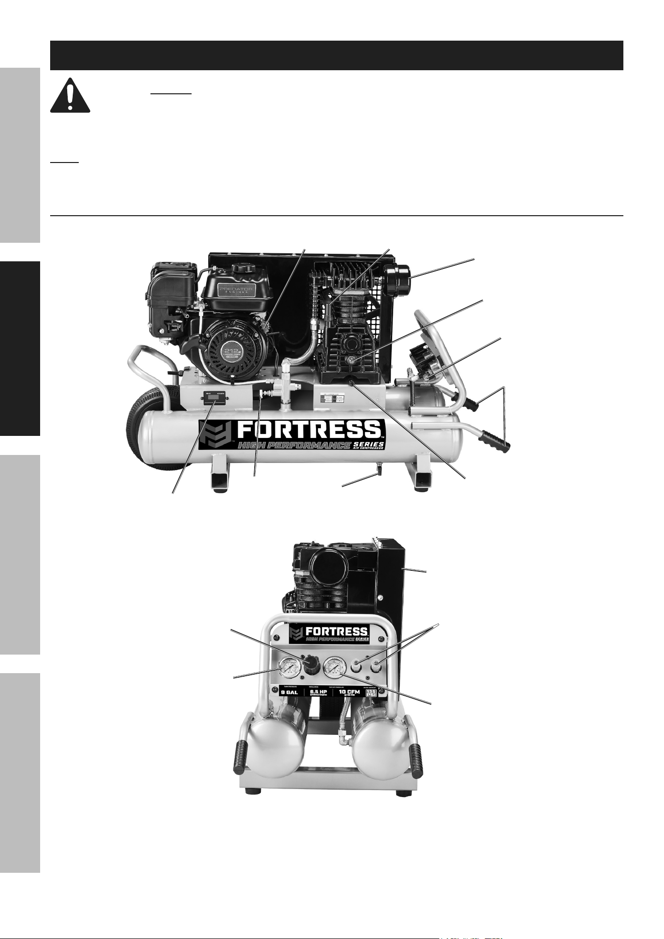
Functions
Oil Fill
Breather
engine
Switch
air Outlets
Oil Sight
Glass
Oil Drain
plug
air Filter
Belt Guard
Handles
pilot
Valve
Safety
Valve
Hour
Meter
Drain
Valve x2
Outlet
pressure
Gauge
tank
pressure
Gauge
regulator
The emission control system for this Compressor’s Engine is warranted for standards set
by the U.S. Environmental Protection Agency and by the California Air Resources Board
(also known as CARB). For warranty information, refer to the engine manual.
Page 9For technical questions, please call 1-800-444-3353.Item 70734
SaFetyOperatiOnMaintenance inStallatiOn
Belt Guard ‑ Encloses the pulleys and drive belts.
Protects the user from the moving parts and allows
the pulley to direct cooling air to the Air Pump.
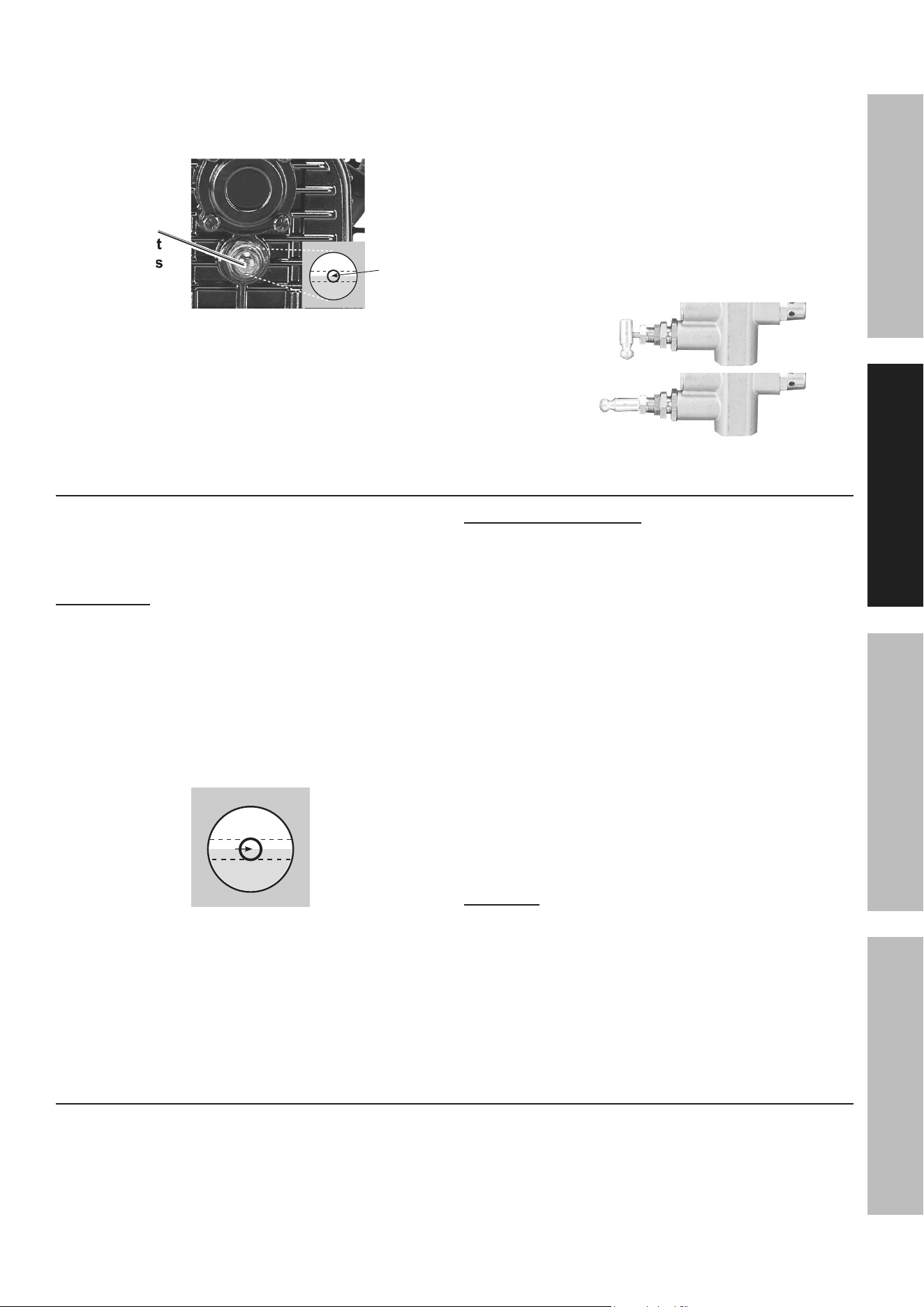
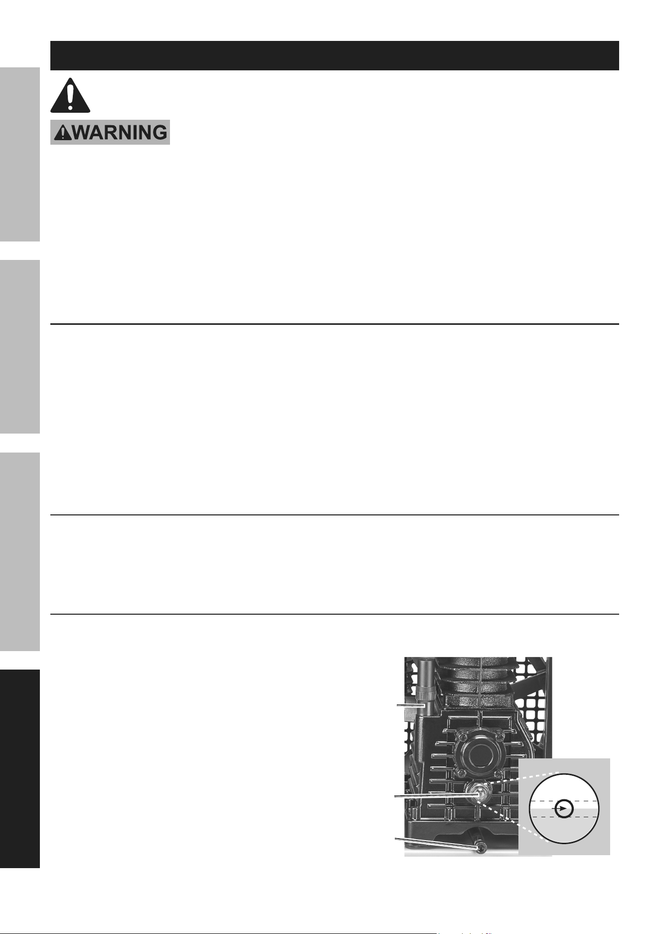
Oil Sight Glass - Shows proper level of the oil.
Oil level should be at center of Sight Glass.
Oil
Sight
Glass
Sight
Glass
Oil leVel
OVerFill
lOW
Full
Drain Valves - Allows moisture to be
removed from tanks to prevent corrosion.
Safety Valve - Automatically releases air
if Air Tank pressure exceeds the preset
maximum. In an emergency, the ring can
be pulled to relieve tank air pressure.
air tanks - Air pressurized by the
Pump is stored for use.
tank pressure Gauge - Displays
the air pressure in the tanks.
Outlet pressure Gauge - Displays
the air pressure going to tool.
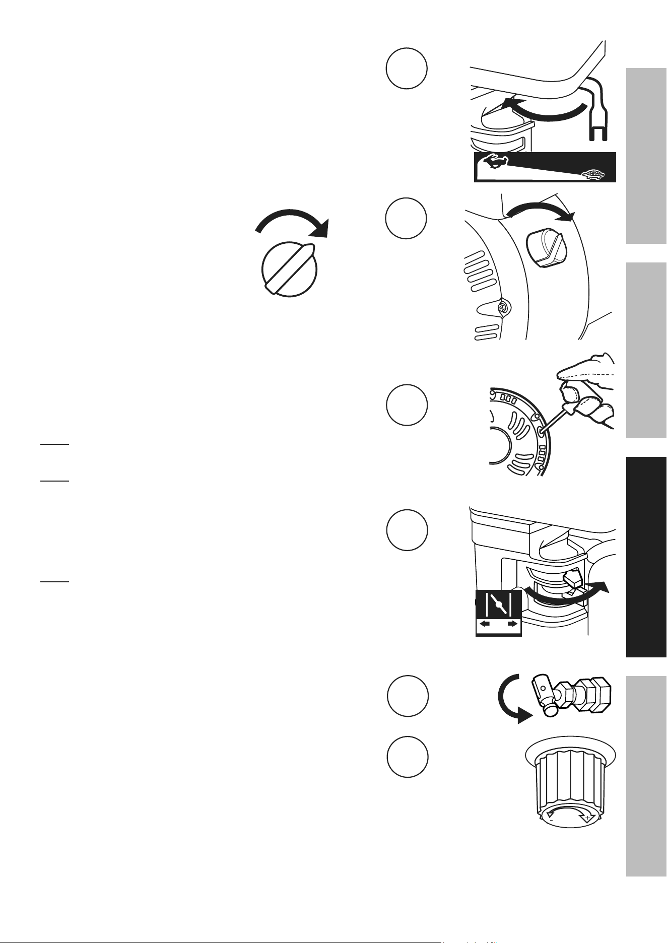
pilot Valve - Open the Pilot Valve before
starting the engine. It relieves resistance on
the engine to make starting possible. Rotate the
pin so it is horizontal to open it. Once the
engine is running, close the Pilot Valve so
the Compressor can build up pressure.
Open
pilot Valve
closed
pilot Valve
checking the Oil
1. Check the oil level before operation.
Fill the Pump Crankcase with
SAE 30W, non‑detergent,
Air Compressor Oil (sold separately).
iMpOrtant: running the air compressor
with no oil or low oil will cause damage to
the equipment and void the warranty.
2. The oil level should be at the center of the “full” level
on the Oil Sight Glass, as shown in the illustration.
Add oil as needed to maintain this level.
Do not let the oil level go below the center dot
(LOW as shown below) and do not overfill
the oil so that it is above the center dot
(OVERFILL as shown below).
OVerFill
lOW
FUll
3. To add oil:
a. Remove the Oil Fill Breather.
b. Using a funnel to avoid spills, pour enough
oil into the Pump Crankcase to reach
the “full” level in the Oil Sight Glass.
c. Replace the Oil Fill Breather.
cold Weather Operation
Premium quality 30‑weight, non‑detergent air
compressor oil (sold separately) is recommended
for use with this compressor. Start compressor in
heated area if outdoor temperatures drop below
32° F. If this is not practical, drain out the old
pump oil and use SAE 10W Non‑detergent Air
Compressor Oil in the pump crankcase instead
whenever the compressor’s temperature will fall
below 40°. Do not use multi‑viscosity oil (such
as 10W‑30), they leave carbon deposits on pump
components and lead to accelerated failure. Heavy
operation may require heavier viscosity oil.
4. If uncertain which oil to use for this compressor,
call Harbor Freight Tools customer service
at 1‑800‑444‑3353 for assistance.
5. change the compressor oil after the first
hour of use to remove any debris, as
described in Changing Oil on page 14.
caUtiOn! tO preVent inJUry FrOM BUrnS:
Do not add or change the oil while
the compressor is in operation.
allow the compressor to cool before replacing oil.
Breaking in the compressor
1. Turn Engine off.
2. Open Pilot Valve.
3. Check all fluid levels in engine and pump.
4. Start engine following the General
Operating Instructions.
5. Close Pilot Valve.
6. Let the unit run for 30 minutes.
7. Turn Engine OFF.
Page 10 For technical questions, please call 1-800-444-3353. Item 70734
SaFety OperatiOn MaintenanceinStallatiOn
Operating instructions
read the entire iMpOrtant SaFety inFOrMatiOn section at the beginning of this
manual including all text under subheadings therein before set up or use of this product.
Using the compressor
Inspect Compressor, engine, pump and equipment looking for damaged, loose, and missing parts
before set up and starting. If any problems are found, do not use equipment until fixed properly.
note: At the beginning of the day’s first use of the Air Compressor, check for air leaks by applying soapy water to
connections while the Air Compressor is pumping and after pressure cut‑out. Look for air bubbles. If air bubbles
are present at connections, tighten connections. Do not use the air compressor unless all connections are air tight.
The extra air leaking out will cause the compressor to operate too often, increasing wear on the compressor.
Before starting the compressor:
a. Follow the Set Up instructions in the equipment manual to prepare the equipment.
b. Follow the Set Up instructions in the engine manual to prepare the engine.
c. inspect all components of the setup. Make sure all nuts and bolts are tight.
d. Fill the engine with the proper amount and type of both fuel and oil.
e. Fill the compressor pump with compressor oil following
the Maintenance instructions in this manual.
f. replace the plug on the crankcase with the Oil Fill Breather.
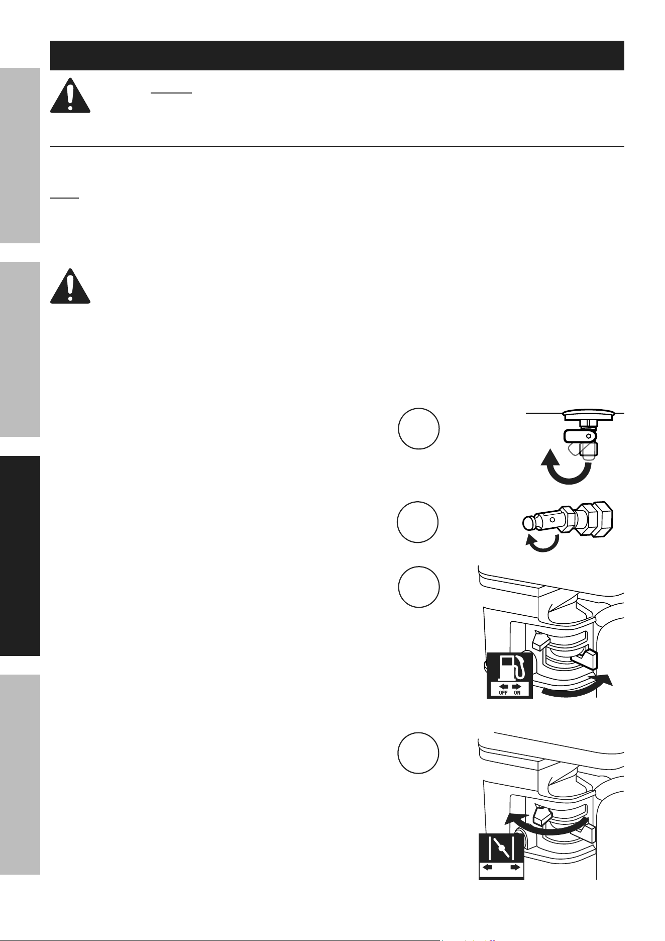
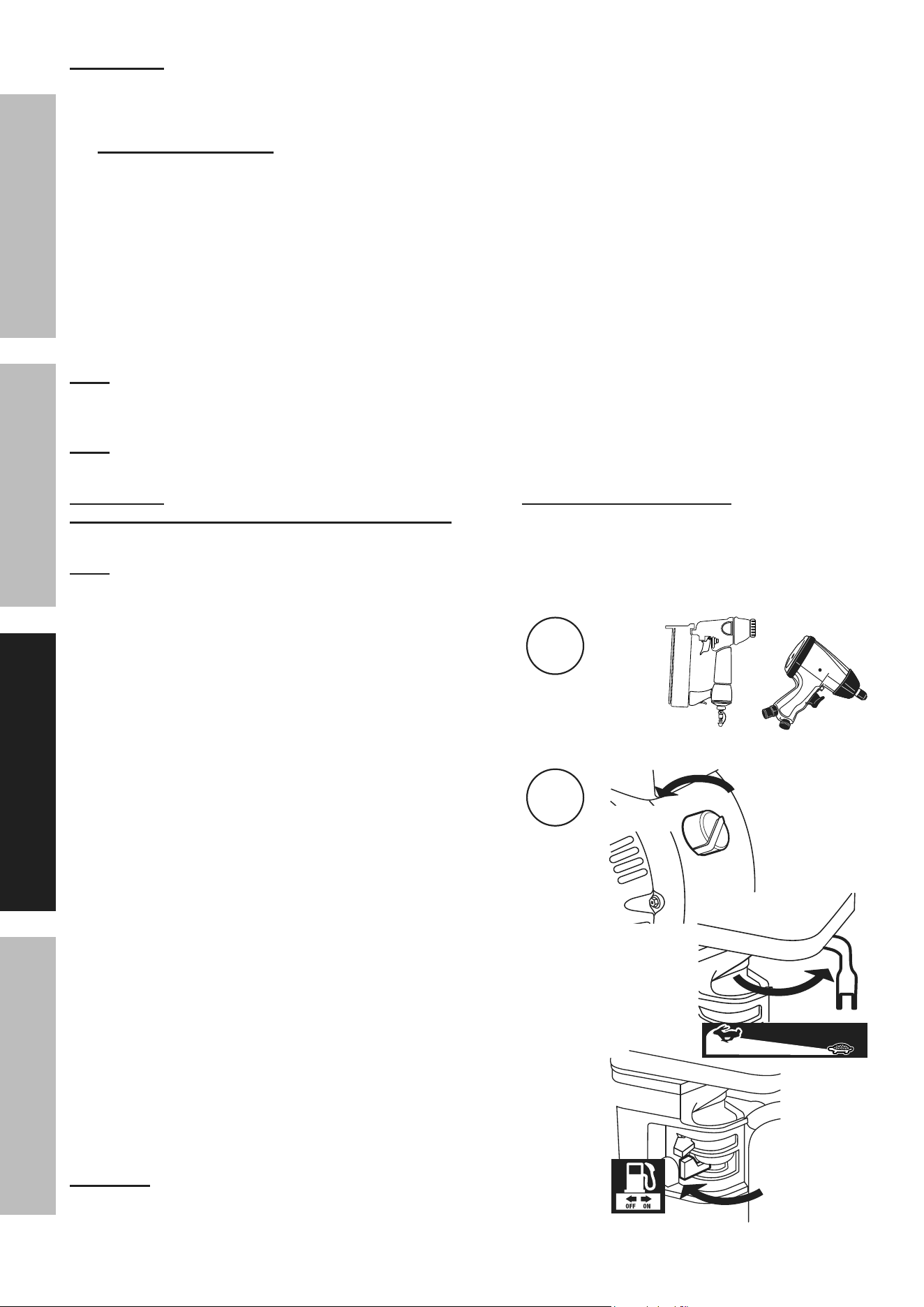
to Start and Use the compressor
1. Close both Drain Valves.
2. Open the Pilot Valve by rotating it to horizontal position.
3. Move the Fuel Valve to the ON position.
4. To start a cold engine, move the Choke Lever to
START (choked) position.
To restart a warm engine, leave the
Choke Lever in the RUN position.
1
2
3
4
Start rUn
Page 11For technical questions, please call 1-800-444-3353.Item 70734
SaFetyOperatiOnMaintenance inStallatiOn
5. Slide the Throttle / Speed Control Lever to 1/3
away from the SLOW position (the “turtle”).
6. Turn the Engine Switch ON.
7. Grip the Starter Handle of the Engine loosely and pull
it slowly several times to allow the gasoline to flow into
the Engine’s carburetor. Then pull the Starter Handle
gently until resistance is felt. Allow Cable to retract fully
and then pull it quickly. Repeat until the engine starts.
note: Do not let the Starter Handle snap back against the
engine. Hold it as it recoils so it doesn’t hit the engine.
note: If engine does not start, check engine oil. Engine
will not start with low or no engine oil.
8. Allow the Engine to run for several
seconds. Then, if the Choke Lever is in the
START (choked) position, move the Choke
Lever very slowly to the RUN position.
note: Moving the Choke Lever too fast could kill the engine.
9. Close the Pilot Valve by rotating it to vertical position.
10. When the Gas Engine is running, the compressor
Pump starts compressing air into the Air Tank.
Adjust the Pressure Regulator so that the air output
is enough to properly power the tool, but the output
will not exceed the tool’s maximum air pressure at
any time. Turn the knob clockwise to increase the
pressure and counterclockwise to decrease pressure.
Adjust the pressure gradually, while checking
the air output gauge to set the pressure.
5
On
OFF
O
i
On
6
7
8
Start rUn
9
10
Page 12 For technical questions, please call 1-800-444-3353. Item 70734
SaFety OperatiOn MaintenanceinStallatiOn
iMpOrtant: Allow the engine to run for five minutes with no load
after each start‑up so that the engine can stabilize.
11. Adjust the Throttle / Speed Control Lever as needed.
12. engine Break-in period:
a. Breaking‑in the engine will help to ensure proper equipment and engine operation.
b. The operational break‑in period will last about 3 hours of use. During this period:
• Do not apply a heavy load to the equipment.
• Do not operate the engine at its maximum speed.
c. The maintenance break‑in period will last about 20 hours of use. After this period:
• Change the engine oil.
Under normal operating conditions subsequent maintenance follows the schedule
explained in the MAINTENANCE AND SERVICING section.
note: When maximum tank pressure is reached, the compressor automatically disengages, and the engine
RPM drops down to idle speed. The engine remains at idle until Air Tank pressure falls to a preset level.
The Gas Engine will then accelerate and air pressure once again begins to build up in the Air Tank.
note: As long as the engine is running, the operation of the Air Compressor
is automatic, controlled by an internal pressure switch.
iMpOrtant: The internal pressure switch is not user adjustable; do not make changes to the
air pressure settings of the internal pressure switch. Any change to the automatic pressure
levels may cause excess pressure to accumulate, causing a hazardous situation.
note: Depressurization - If it is necessary to quickly depressurize the Compressor, turn OFF the engine.
Then, pull on the ring on the tank Safety Valve to release stored air pressure.
13. Use the air tool as needed.
14. To stop the engine in an emergency,
turn the Engine Switch off.
Under normal conditions, use the following procedure:
a. Slide the Throttle / Speed Control
Lever to SLOW (the “turtle”).
b. Turn the Engine Switch off.
c. Close the Fuel Valve.
WarninG! tO preVent SeriOUS inJUry: the fuel valve must be
closed before moving the engine to prevent fuel leakage and fire.
13
14
O
i
OFF

Page 13For technical questions, please call 1-800-444-3353.Item 70734
SaFetyOperatiOnMaintenance inStallatiOn
15. Bleed air from the tool, then disconnect the tool.
16. Drain Air Tanks according to Draining
Moisture from the Tanks on page 15.
17. Clean, then store the Air Compressor indoors.
emergency Depressurization
If it is necessary to quickly depressurize the Compressor, turn the Engine Switch OFF.
Then pull the ring on the Safety Valve to quickly release stored air pressure.
15
®®
Page 14 For technical questions, please call 1-800-444-3353. Item 70734
SaFety OperatiOn MaintenanceinStallatiOn
Maintenance and Servicing
procedures not specifically explained in this manual must
be performed only by a qualified technician.
tO preVent SeriOUS inJUry FrOM acciDental OperatiOn:
turn the engine Switch of the equipment to its “OFF” position, release tank air
pressure, wait for the engine to cool, and disconnect the spark plug cap before
performing any inspection, maintenance, or cleaning procedures.
tO preVent SeriOUS inJUry FrOM cOMpreSSOr FailUre:
Do not use damaged equipment. if abnormal noise or vibration occurs,
have the problem corrected before further use.
caUtiOn! tO preVent inJUry FrOM BUrnS: Do not add or change the oil while the
compressor is in operation. allow the compressor to cool before replacing oil.
cleaning, Maintenance, and lubrication
1. BeFOre eacH USe, inspect the general
condition of the air compressor. Check for:
• loose hardware,
• misalignment or binding of moving parts,
• damaged belts,
• cracked or broken parts,
• damaged electrical wiring, and
• any other condition that may
affect its safe operation.
2. aFter USe, wipe external surfaces of
the compressor with a clean cloth.
compressor pump Oil Maintenance
Check oil periodically for clarity. Replace oil if it appears milky or if debris is present, or
every 6 months, or 100 hours of runtime, whichever comes first. In harsh environments
such as high heat or high humidity, replace the oil more frequently.
change compressor oil after first twenty hours of use to remove any debris.
changing Oil
caUtiOn! tO preVent inJUry FrOM BUrnS: Do not add or change the oil while the
compressor is in operation. allow the compressor to cool before replacing oil.
1. Place a container under Oil Drain Plug.
2. Remove Oil Fill Breather to allow
air flow into the Pump.
3. Remove Oil Drain Plug, allowing the
oil to drain into the container.
4. When the oil is completely drained from
the Pump, replace Oil Drain Plug.
5. Fill the Pump with new compressor oil to
the FULL level on Oil Sight Glass.
6. Replace and tighten Oil Fill Breather.
7. Discard old oil according to local,
state and federal regulations.
OVerFill
lOW
FUll
OIL LEVEL
Oil Sight
Glass
Oil Drain
plug
Oil Fill
Breather
Page 15For technical questions, please call 1-800-444-3353.Item 70734
SaFetyOperatiOnMaintenance inStallatiOn
Draining Moisture from the tanks
A Drain Valve is located under each Tank.
They must be used daily to release all trapped
air and moisture from the Tanks. Doing this will
eliminate condensation and prevent tank corrosion.
1. Turn Engine Switch off.
2. Place a collection pan under each Drain Valve.
3. Open both Drain Valves.
4. When all the pressure and moisture is released,
close both Drain Valves.
air Filter Maintenance
Check the Air Filter weekly to see if it needs cleaning or
replacement. If working in dirty environments, you may
need to replace filter more often. To replace Air Filter:
1. Remove Cover and Filter. Check
Filter for accumulated dirt.
2. cleaning:
• For paper filter elements:
To prevent injury from dust and debris,
wear ANSI‑approved safety goggles,
NIOSH‑approved dust mask/respirator,
and heavy‑duty work gloves. In a
well‑ventilated area away from bystanders,
use pressurized air (no more than 15 PSI) to
blow dust out of the air filter. If this does not
get the filter clean, replace it.
• For foam filter elements:
Wash the element in warm water and
mild detergent several times. Rinse.
Squeeze out excess water and allow it to dry
completely. Soak the filter in lightweight oil
briefly, then squeeze out the excess oil.
3. Replace the cleaned Filter and Cover.
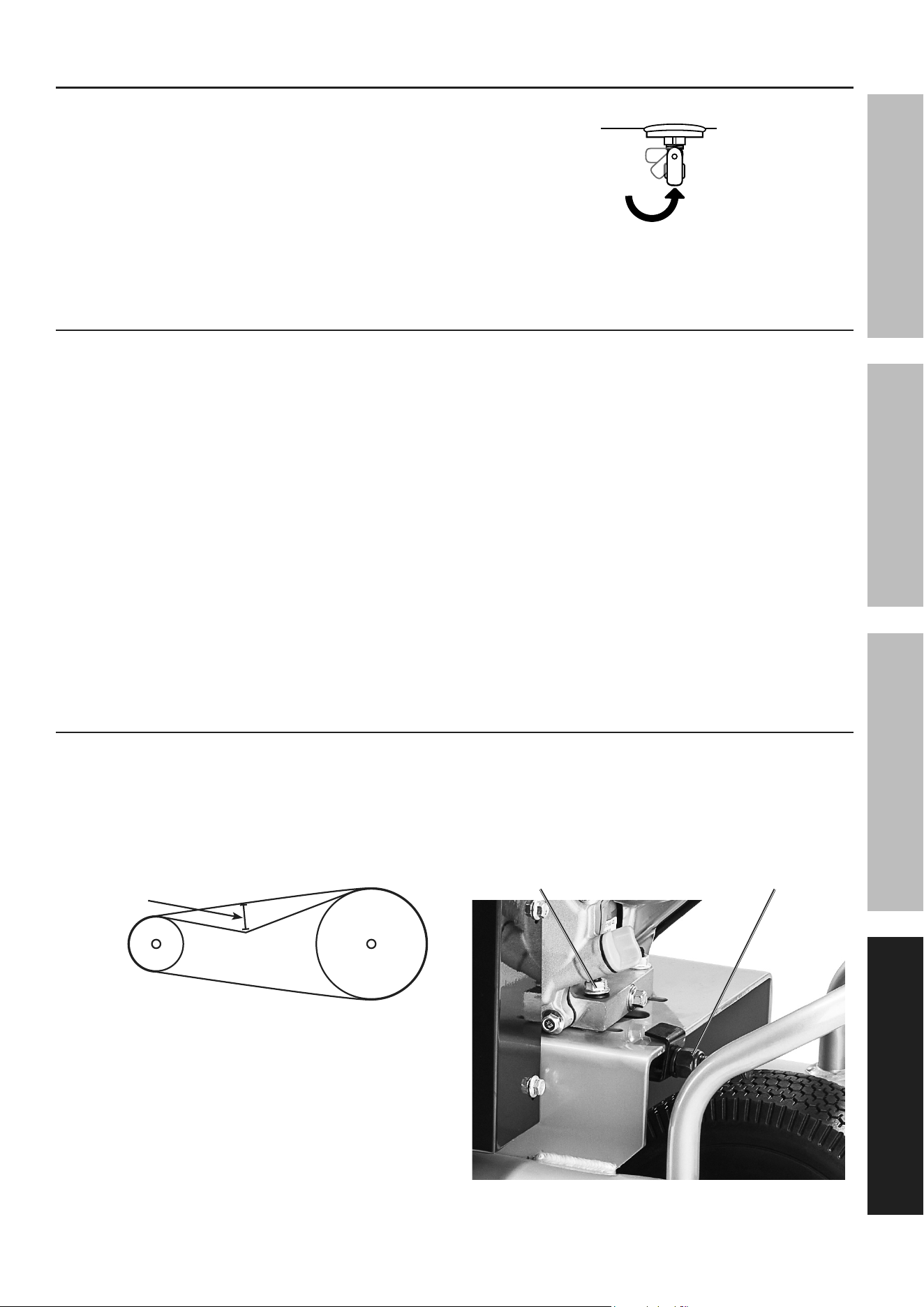
adjusting Belt tension
1. Remove Belt Guard and set it aside.
2. Press on the center of the longest span on each belt
with moderate finger pressure (4‑4.5 lb.).
Then measure the deflection distance,
the distance that the belt moved.
The belt should deflect anywhere from 1/2" to 1".
Deflection
Distance
3. if belt deflects too much, tighten belt by loosening
the four Engine Mount Bolts and turning the
Adjustment Bolt clockwise to shift engine away
from other pulley. Retighten Engine Mount
Bolts and retest tension. If belt is too long to be
properly tensioned, belt must be replaced.
4. if belt deflects too little, loosen belt by loosening
the four Engine Mount Bolts and turning the
Adjustment Bolt counterclockwise to shift the
engine toward the other pulley. Retighten
Engine Mount Bolts and retest tension.
engine
Mount Bolt
adjustment
Bolt
5. Replace Belt Guard before use.

Page 16 For technical questions, please call 1-800-444-3353. Item 70734
SaFety OperatiOn MaintenanceinStallatiOn
Maintenance Schedule
Following are general guidelines for
maintenance checks of the Air Compressor.
note: The environment in which the compressor
is used, and the frequency of use will affect how
often you will need to check the Air Compressor
components and perform maintenance procedures.
Daily:
a. Check oil level.
b. Check for oil leaks.
c. Make sure all nuts and bolts are tight.
d. Drain moisture from air tanks.
e. Check for abnormal noise or vibration.
f. Check for air leaks.
*
g. Inspect belts.
h. Wipe off any oil or dirt from the compressor.
**
Weekly:
a. Inspect Air Filter.
b. Inspect Oil Fill Breather.
Monthly:
a. Inspect Pressure Relief Valve.
b. Inspect vibration isolation pads (if installed).
* To check for air leaks, apply soapy water to joints while
the Air Compressor is pressurized. Look for air bubbles.
** To clean the compressor surface, wipe with
a damp cloth, using a mild detergent or mild solvent.
Page 17For technical questions, please call 1-800-444-3353.Item 70734
SaFetyOperatiOnMaintenance inStallatiOn
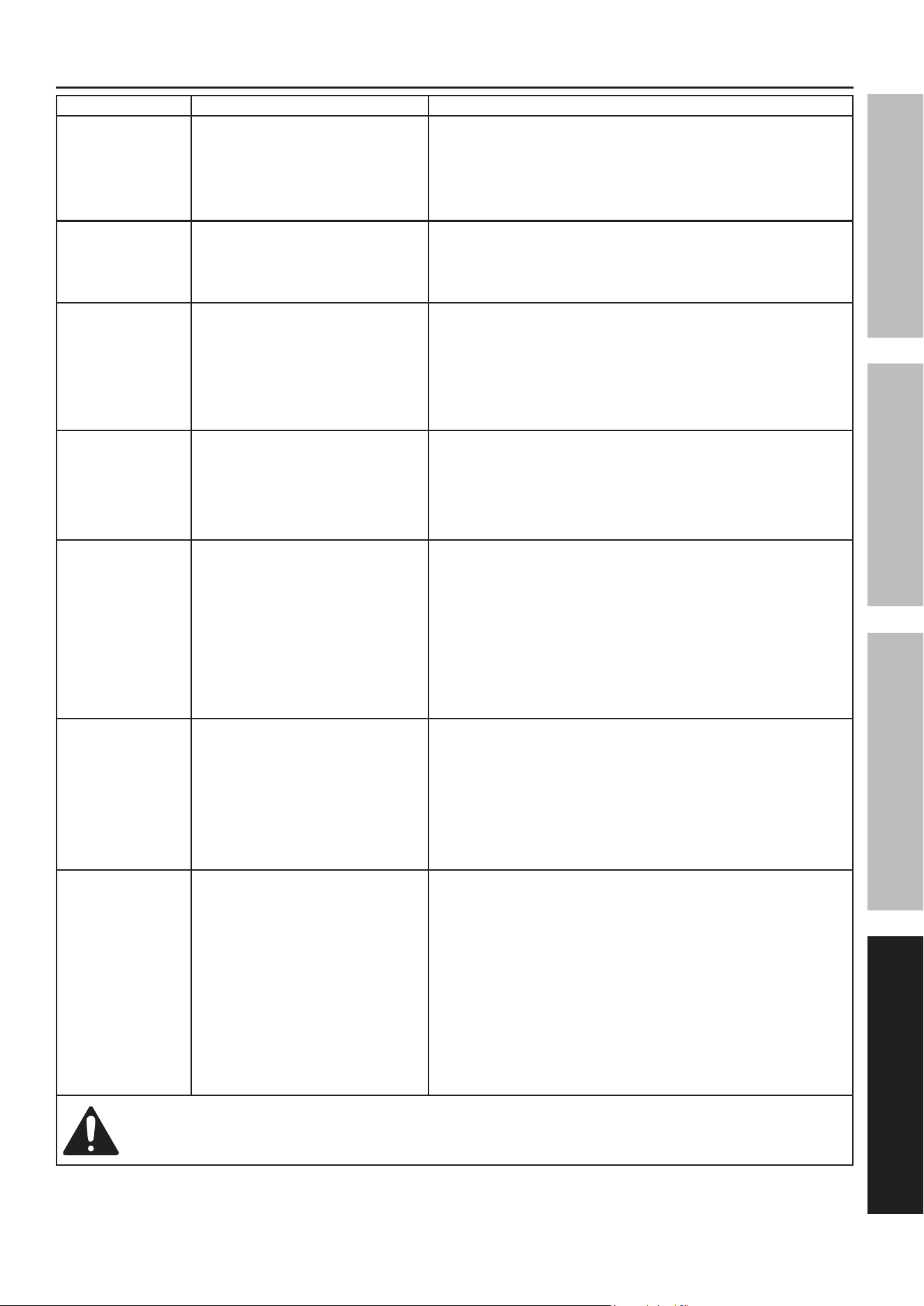
troubleshooting
problem possible causes likely Solutions
Engine will
not start
(Note: See engine
manual for engine
specific issues.)
COMPRESSOR SPECIFIC:
1. Pilot Valve closed.
2. Engine Switch in
″OFF″ position.
COMPRESSOR SPECIFIC:
1. Open pilot valve before start procedure,
close after unit is running.
2. Turn engine to ″ON″ position.
Compressor
overheats
1. Incorrect lubrication or
not enough lubrication.
2. Worn parts.
1. Lubricate using recommended oil or
grease according to directions.
2. Have qualified technician inspect internal
mechanism and replace parts as needed.
Severe air
leakage
1. Poor air outlet seal.
2. Loose cylinder/cylinder head.
3. Damaged valve or housing.
4. Dirty, worn or damaged valve.
1. Tighten or re‑attach using thread seal tape.
2. Tighten cylinder/cylinder head assembly.
If cylinder/cylinder head cannot tighten properly,
internal parts may be misaligned.
3. Replace damaged components.
4. Clean or replace valve assembly.
Unit stalls
1. Low engine idle.
2. Severely clogged air filter.
3. Improper lubrication.
4. Defective pilot/unloader valve.
1. Qualified technician should increase idle to
2,000±100 RPM by adjusting pressure switch.
2. Replace air filter.
3. Check for proper oil level.
4. Replace pilot valve.
Excessive noise
1. Loose drive pulley or flywheel.
2. Misaligned pulleys.
3. Lack of oil in crankcase.
4. Worn connecting rod.
5. Worn wrist pin bushing.
6. Worn bearings.
7. Loose belts.
1. Loose pulleys are a common cause of
“knocking”. Tighten appropriate bolts.
2. Align pulleys with straightedge and secure in place.
3. Check for proper oil level.
4. Replace connecting rod.
5. Remove piston assembly and replace necessary parts.
6. Replace bearings and oil.
7. Check for proper belt tension.
Oil in the
discharge air
1. Wrong type of oil or
low‑quality oil.
2. Overheating.
3. Restricted intake air.
4. Worn piston rings.
5. Excessive moisture
in the tanks.
1. Change oil. Check oil recommendations under
Maintenance section of this manual.
2. See above Excessive Noise section.
3. Clean or replace air filter.
4. Replace piston rings.
5. Drain moisture from the tanks daily.
Low discharge
pressure
1. Air leaks.
2. Leaking valves.
3. Restricted air intake.
4. Blown gaskets.
5. Slipping belt.
1. Listen for escaping air. Apply soap solution
to all fittings and connections. Bubbles will
appear at points of leakage. Tighten or
replace leaking fittings or connections.
2. Remove head and inspect for valve breakage,
weak valves, scored valve plate, etc. Replace
defective parts and reassemble. Replace head
gasket each time the head is removed.
3. Clean or replace air filter element.
4. Replace if gaskets proven faulty on inspection.
5. Tighten Belt (See Maintenance.)
Follow all safety precautions whenever diagnosing or servicing the equipment or engine.
Page 18 For technical questions, please call 1-800-444-3353. Item 70734
SaFety OperatiOn MaintenanceinStallatiOn
parts list and Diagram
pleaSe reaD tHe FOllOWinG careFUlly
THE MANUFACTURER AND/OR DISTRIBUTOR HAS PROVIDED THE PARTS LIST AND ASSEMBLY DIAGRAM
IN THIS MANUAL AS A REFERENCE TOOL ONLY. NEITHER THE MANUFACTURER OR DISTRIBUTOR
MAKES ANY REPRESENTATION OR WARRANTY OF ANY KIND TO THE BUYER THAT HE OR SHE IS
QUALIFIED TO MAKE ANY REPAIRS TO THE PRODUCT, OR THAT HE OR SHE IS QUALIFIED TO REPLACE
ANY PARTS OF THE PRODUCT. IN FACT, THE MANUFACTURER AND/OR DISTRIBUTOR EXPRESSLY
STATES THAT ALL REPAIRS AND PARTS REPLACEMENTS SHOULD BE UNDERTAKEN BY CERTIFIED AND
LICENSED TECHNICIANS, AND NOT BY THE BUYER. THE BUYER ASSUMES ALL RISK AND LIABILITY
ARISING OUT OF HIS OR HER REPAIRS TO THE ORIGINAL PRODUCT OR REPLACEMENT PARTS
THERETO, OR ARISING OUT OF HIS OR HER INSTALLATION OF REPLACEMENT PARTS THERETO.
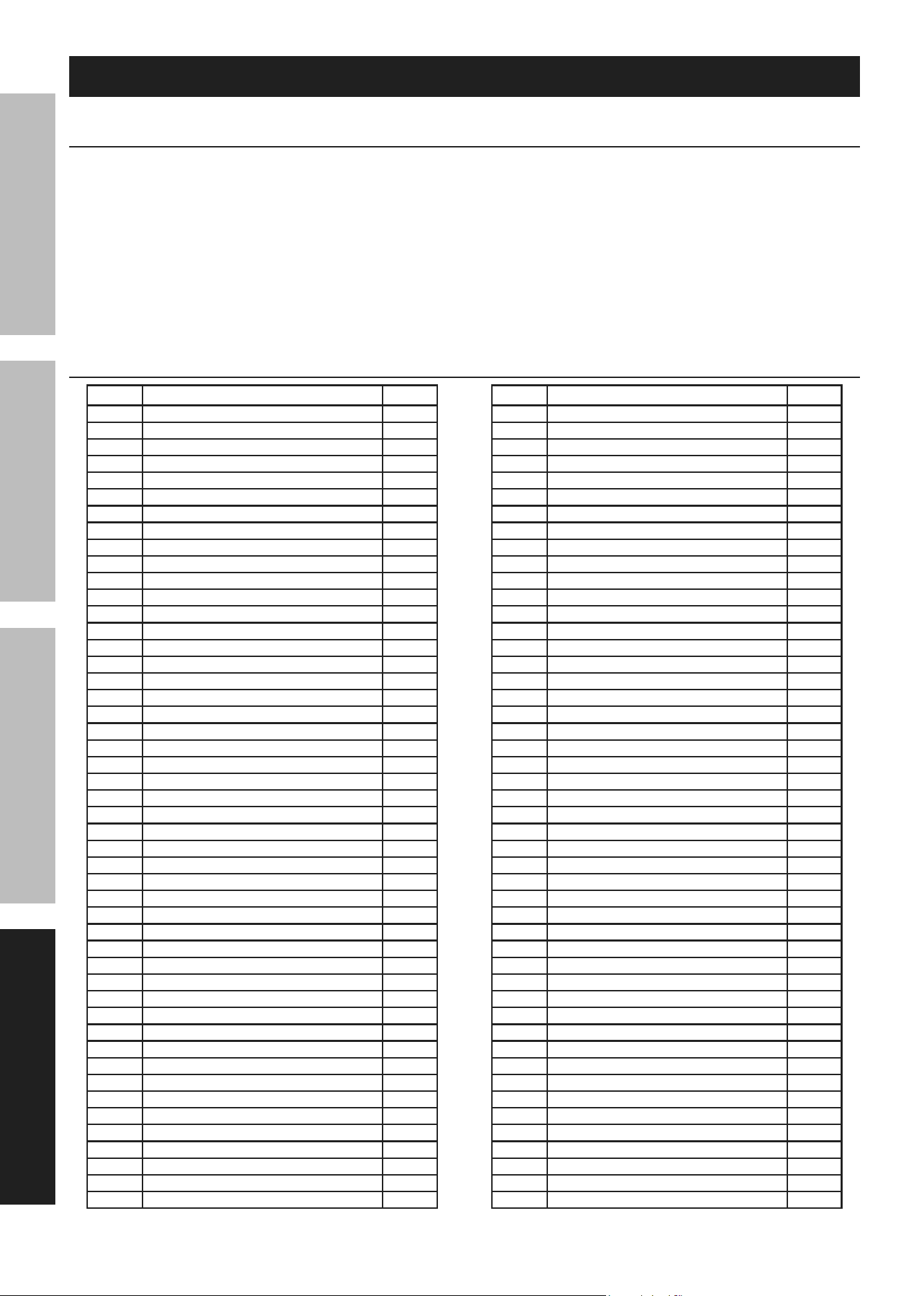
parts list
part Description Qty
1 Tank 1
2 Hour Meter 1
3 Flat Washer 2
4 Socket Cap Screw 2
5 Cotter Pin 2
6 Axle 1
7 10″ Wheel 1
8 Adjustment Bolt 1
9 Adjustment Bracket 1
10 Snap Bushing 1
11 M6 Socket Bolt 12
12 Oil Drain Plug 1
13 O‑Ring 1
14 Baseplate 1
15 Baseplate Seal 1
16 Oil Sight Glass Seal 1
17 Oil Sight Glass 1
18 Back Cover Gasket 1
19 Back Cover 1
20 Flat Washer 4
21 M6 Hex Bolt 4
22 Pilot Valve 1
23 Connector 1
24 Control Tube 1
25 Elbow Connector 1
26 Exhaust Pipe 1
27 M10 Engine Mount Bolt 4
28 O‑Ring 1
29 Oil Fill Breather 1
30 Connecting Rod 2
31 Piston 2
32 Piston Pin 2
33 Pin Clip 4
34 Oil Ring 2
35 Compressing Ring 4
36 M8 Socket Bolt 6
37 Cylinder Gasket 1
38 Cylinder 1
39 Valve Plate Gasket 1
40 Valve Plate 2
41 Copper Gasket 1
42 Head Cover Gasket 1
43 Air Filter 1
44 Head Cover 1
45 Flat Washer 6
46 Spring Washer 6
47 M8 Socket Bolt 6
48 After‑cooler Gasket 1
part Description Qty
49 Exhaust Connector 1
50 After‑cooler 1
51 M8 Socket Bolt 2
52 Elbow Connector 1
53 Throttle Control Valve 1
54 Steel Wire 1
55 Engine 1
56 Flat Washer 4
57 M8 Hex Bolt 4
58 Pulley 1
59 Key 1
60 Nut 4
61 Cover Screw 7
62 Belt Guard Cover 1
63 Flywheel Bolt 1
64 Flywheel Flat Washer 1
65 V‑Belt 1
66 Flywheel 1
67 M6 Socket Bolt 7
68 Flat Washer 7
69 Belt Guard 1
70 Cushion 1
71 M8 Socket Bolt 2
72 Flat Washer 2
73 Support Bracket 2
74 M6 Socket Bolt 4
75 Flat Washer 4
76 Front Cover 1
77 Front Cover Gasket 1
78 Oil Seal 1
79 Ball Bearing 6205 1
80 Crankshaft 1
81 Ball Bearing 6205 1
82 Crankcase 1
83 Flat Washer 4
84 Nut 4
85 Regulator Knob 1
86 Torx Screw 8
87 Control Panel 1
88 Air Outlet 2
89 Outlet Pressure Gauge 1
90 Tank Pressure Gauge 1
91 Elbow Connector 1
92 Connecting Pipe 1
93 Safety Valve 1
94 Regulator 1
95 Elbow Connector 1
96 Handle 2
Page 19For technical questions, please call 1-800-444-3353.Item 70734
SaFetyOperatiOnMaintenance inStallatiOn
part Description Qty
97 Drain Valve 2
98 Nut 4
99 Foot 4
part Description Qty
100 Flat Washer 4
101 M8 Hex Bolt 4
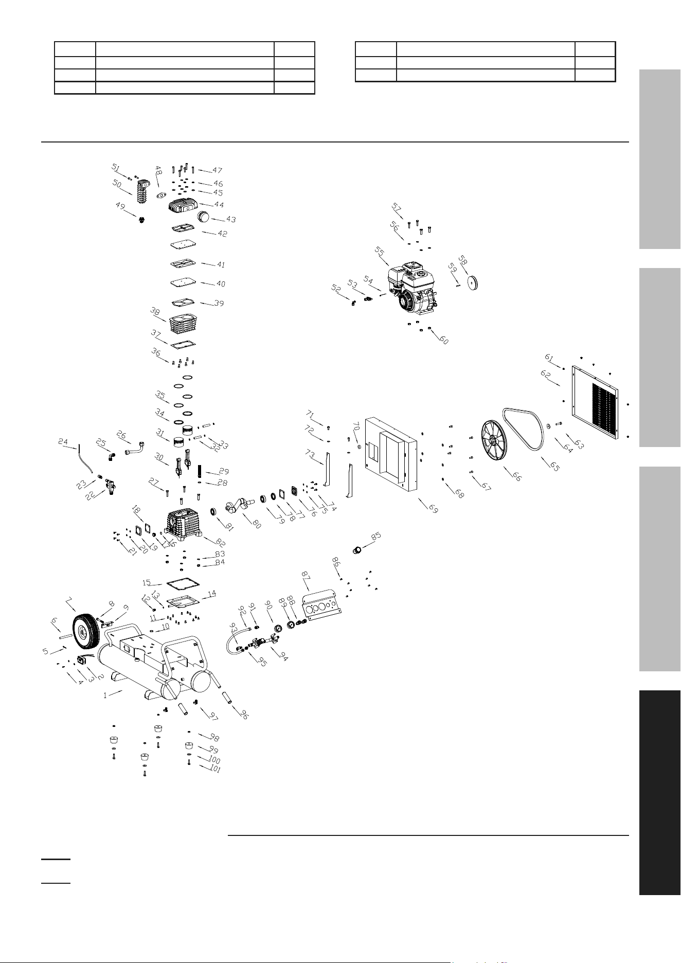
assembly Diagram
record product’s Date code Here:
note: if product has no date code, record month and year of purchase instead.
note: Some parts are listed and shown for illustration purposes only, and are not
available individually as replacement parts. Reference UPC 193175510303.

26677 agoura road • calabasas, ca 91302 • 1-800-444-3353
®®
limited 90 Day Warranty
Harbor Freight Tools Co. makes every effort to assure that its products meet high quality and durability standards,
and warrants to the original purchaser that this product is free from defects in materials and workmanship for the
period of 90 days from the date of purchase. This warranty does not apply to damage due directly or indirectly,
to misuse, abuse, negligence or accidents, repairs or alterations outside our facilities, criminal activity, improper
installation, normal wear and tear, or to lack of maintenance. We shall in no event be liable for death, injuries
to persons or property, or for incidental, contingent, special or consequential damages arising from the use of
our product. Some states do not allow the exclusion or limitation of incidental or consequential damages, so
the above limitation of exclusion may not apply to you. THIS WARRANTY IS EXPRESSLY IN LIEU OF ALL
OTHER WARRANTIES, EXPRESS OR IMPLIED, INCLUDING THE WARRANTIES OF MERCHANTABILITY
AND FITNESS, EXCEPT FOR THE EMISSIONS CONTROL SYSTEM WARRANTY BELOW.
To take advantage of this warranty, the product or part must be returned to us with transportation charges prepaid.
Proof of purchase date and an explanation of the complaint must accompany the merchandise. If our
inspection verifies the defect, we will either repair or replace the product at our election or we may elect to
refund the purchase price if we cannot readily and quickly provide you with a replacement. We will return
repaired products at our expense, but if we determine there is no defect, or that the defect resulted from
causes not within the scope of our warranty, then you must bear the cost of returning the product.
This warranty gives you specific legal rights and you may also have other rights which vary
from state to state. HFT also warrants that the emissions control system on your engine is
designed, built, and equipped so that it conforms to the United States Environmental Protection
Agency’s (EPA) emissions requirements in effect at the time of manufacture.
