24708
EN
Original Instructions
Version 1
April 2024
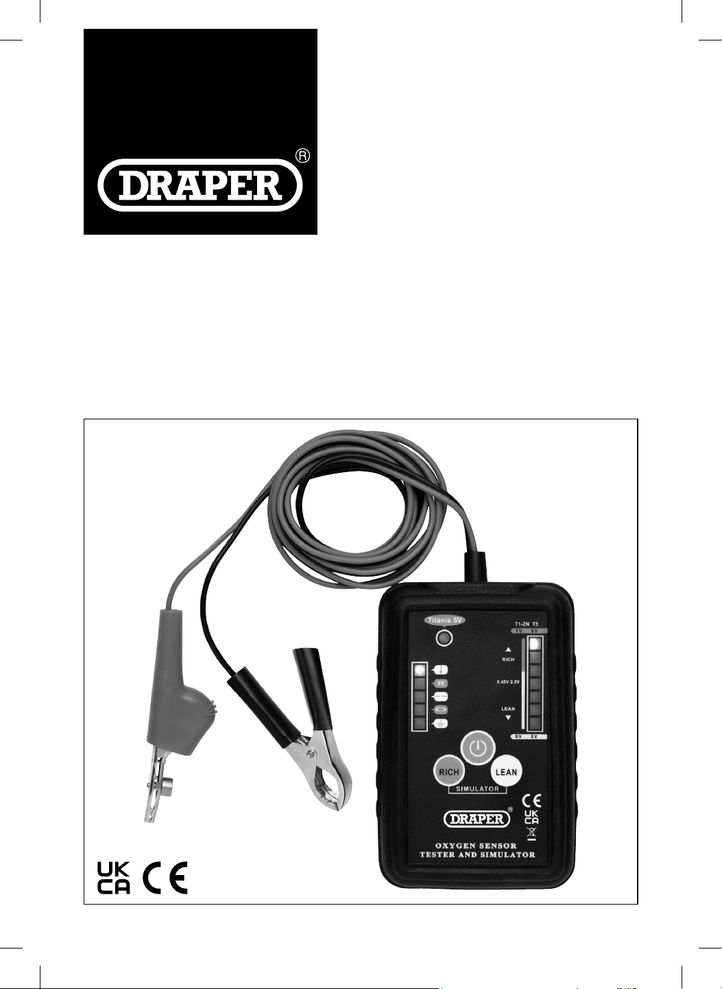
12V
LAMBDA TEST
& SIMULATOR

User Manual for: Lambda Test & Simulator
Stock No: 24708
Part No: ETOT
Read this manual in full before using this product and
retain it for future use. Always use the latest version of
the manual.
Please visit drapertools.com/manuals for the
latest version.
1.
– 2 –
EN
2. Product Introduction
2.1 Intended Use
This 12V oxygen sensor tester and simulator is designed
for testing Zirconia & Titania lambda/oxygen sensors.
Suitable for testing 1 to 4 wire lambda/oxygen sensors
(heated and unheated) and to simulates rich/lean mixture
to monitor ECU response. A wire piercing clamp is
included for the positive lead for swift connection
checking & conrming the wire identity.
Any other application beyond the conditions established
for use will be considered misuse. Draper Tools accepts
no responsibility for improper use of this product.
2.2 Specication
Stock No. 24708
Part No. ETOT
Power Supply: 12V DC
Zirconia: 1V
Titania: 1V & 5V
Fuel Type: Petrol & Diesel
Net Weight: 311g
Tester Dimensions (L X W X H): 140 X 90 X 35mm
Tester Battery: 9V (not supplied)
Positive Lead Length: 2m
Negative Lead Length: 2m
3. Health and Safety Information
– 3 –
EN
4. Symbols
Important: Read all the Health and Safety instructions before attempting to operate, maintain or repair this product.
Failure to follow these instructions may result in injury or damage to the user, the product or the vehicle.
WARNING!
• ALWAYS follow the instructions and procedures listed
in the vehicle’s service manual before using this
device.
• Keep the tester in good working order and condition.
• DO NOT operate the tester with damaged leads or it
has been dropped, get it checked by a qualied
service representative.
• ALWAYS use in a well-ventilated room and avoid
breathing in the exhaust emission and vapour.
• ALWAYS wear eye protection and appropriate
protective clothing.
• This tester should only be used by qualied personnel.
• Switch o the power before disconnecting any wires.
• To avoid electric shocks, DO NOT touch conductors
with your bare hands.
• DO NOT touch any high temperature parts and do not
touch any rotating or moving parts.
CAUTION! To avoid injury or damage to the
device or wires, connect the tester to the vehicle
before turning the engine on.
Read the instruction manual
Warning!
Do not incinerate or throw onto re
Wear face mask and safety glasses
Keep out of the reach of children
WEEE –
Waste Electrical & Electronic Equipment
Do not dispose of Waste Electrical & Electronic Equipment
in with domestic rubbish
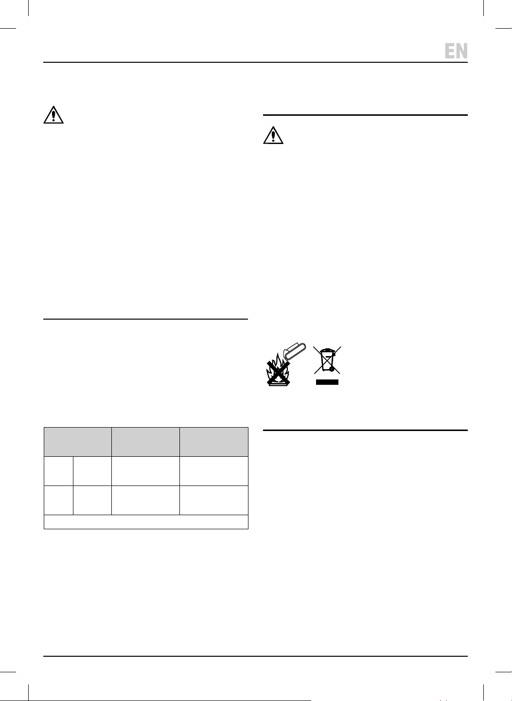
Do not incinerate or throw onto re
WEEE –
Waste Electrical & Electronic Equipment
Do not dispose of Waste Electrical & Electronic Equipment
in with domestic rubbish
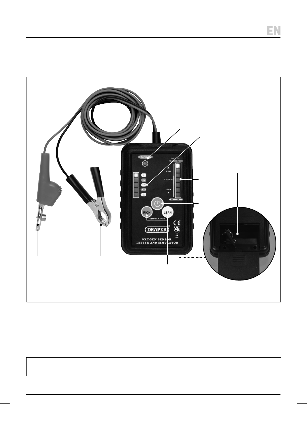
5. Identication
– 4 –
EN
(1) Ground clip (black)
(2) Wire piercing clip (red)
(3) 5V sensor indicator light
(4) Wire indicator lights
(5) Signal Rich/Lean indicator light
(6) Power button
(7) Lean button
(8) Rich button
(9) Battery compartment
(10) Tester protective cover
Please visit drapertools.com for our full range of accessories and consumables.
Carefully remove the product from the packaging and
examine it for any signs of damage that may have
occurred during shipment. If any part is damaged or
missing, do not attempt to use the product.
Please contact the Draper Helpline; contact details can
be found at the back of this manual.
(2)
(3)
(4)
(6)
(5)
(8) (7)
(10)
(9)
(1)
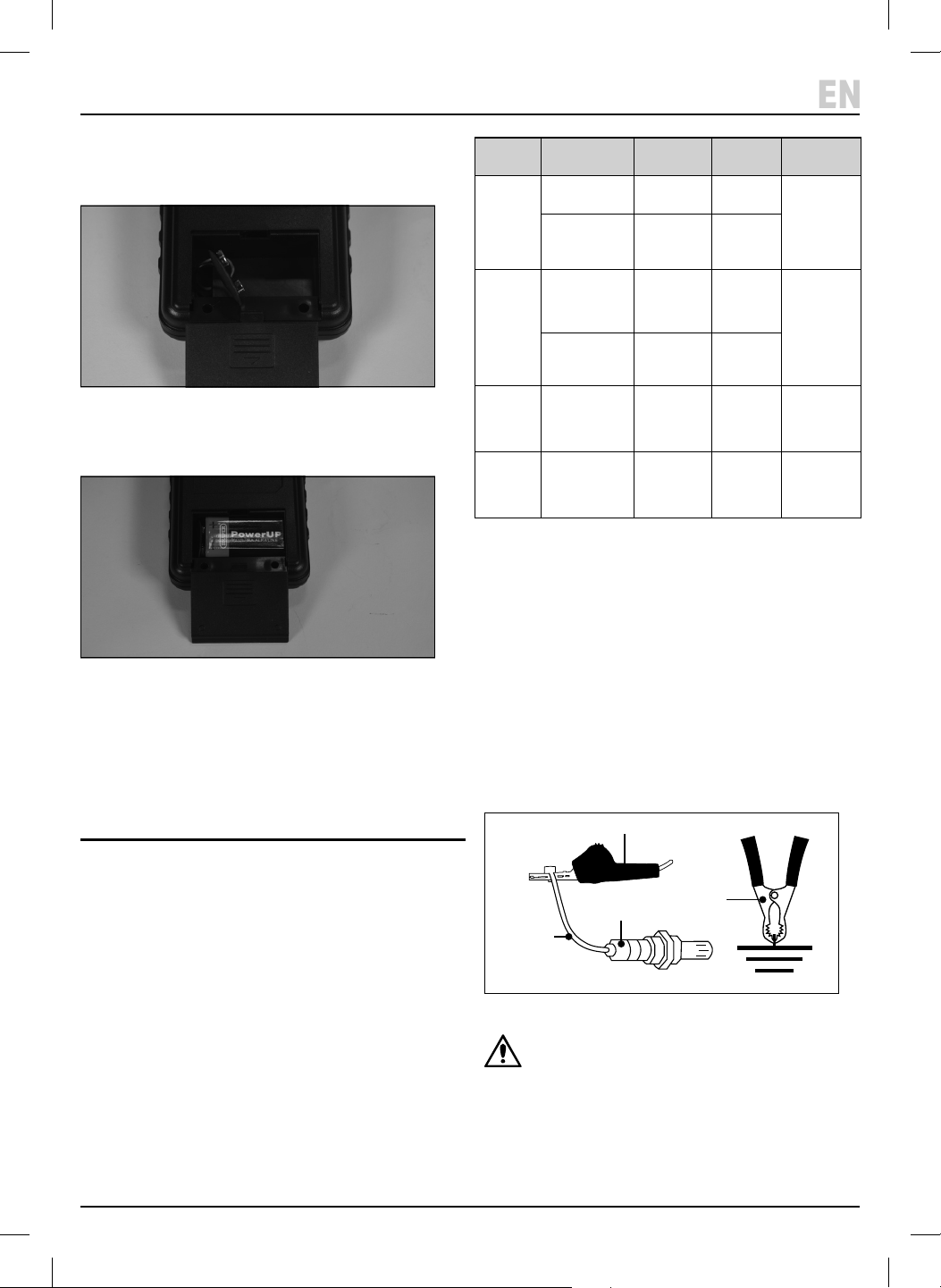
6. Battery Installation
7. Before Operation
– 5 –
EN
1. To t or replace the battery, remove the protective
cover (10) from the tester and unclip the battery
compartment cover (9).
1 Fig.
2. Fit 1 X 9V battery – ensuring that the battery is tted
in the correct +/- orientation.
2 Fig.
3. Clip the cover back on and replace the protective
cover.
• Note: The low battery indicator will light up when the
battery needs changing.
7.1 Before Connecting the sensor
Important: Before operating this product, read and
understand all the safety instructions listed in this
manual.
Important: Before connecting the tester ensure the
engine is o and the exhaust system has cooled down.
• The oxygen sensor can test and simulate popular
oxygen sensors. Select the correct sensor type to be
tested.
1. When the ‘POWER’ button (6) is pressed on the tester will
default to 1V Zirconia an 1V Titanium oxygen sensor.
2. To switch to the 5V Titanium oxygen sensor press and
hold the ‘RICH’ button (8), then press the ‘POWER’
button. The ‘5V Sensor indicator light’ will come on.
7.2 Connecting the Oxygen Sensor
1. Connect the red clip (2) to the signal wire.
2. Then connect the black clip (1) to ground or the
negative terminal of the vehicle’s battery.
3. The ‘Signal Indicators’ (5) and the ‘Wire indicators’
will light up to indicate the type of fuel mixture and
type of connected wire.
3 Fig.
CAUTION: there is no standard colour for oxygen
sensor wires, refer to the manufacturer’s service
manual for guidance.
Sensor
type
Version Working
Temperature
Output
Voltage
If working
correctly
Zirconia
(Zirconium
Dioxide)
Without heater
(single wire)
315 - 425°C 0.45V
Signal
indicator
ows from low
to high 8
times within
10 seconds.
With heater
(2 – 4 wires)
315 - 425°C 0.45V
Titanium
(Titanium
Dioxide)
With heater
(2 – 4 wires)
1V Power supply
426 - 500°C
0.1 – 1V
Best 0.5V
Signal
indicator
ows from low
to high 8
times within
10 seconds.
With heater
(2 – 4 wires)
5V Power supply
426 - 500°C
5V – 0V
Best 2.5V
Wide Band
Single Cell
Disconnect
signal wire from
vehicle. Heater
wire connected
As Titanium As Titanium As Titanium
Wide Band
Dual Cell
Two Zirconia cells
– one oxygen
sensor and one
oxygen pump.
N/A 0.45V
Steady signal
near 0.45V
(2)
Signal wire
Oxygen sensor
Ground
(1)
7. Before Operation 8. Testing Oxygen Sensor
– 6 –
EN
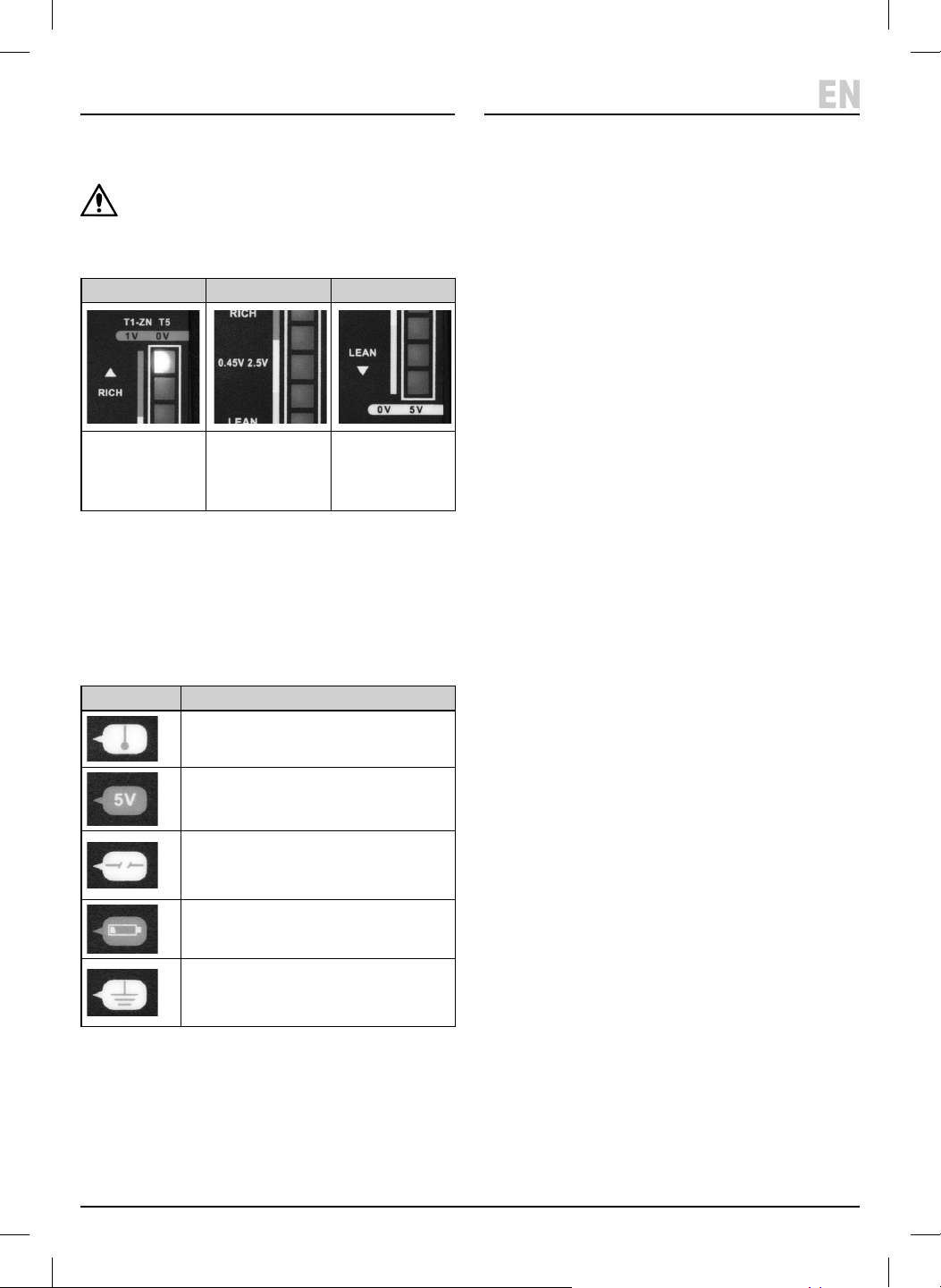
7.3 Signal Indicator Lights (5)
CAUTION: If only the top two indicator lights are
ashing with 1V Zirconia and 1V Titanium mode
the connected sensor is 5V Titanium. Switch o
and change to 5V Titanium mode (Refer to 7.1).
7.4 Identifying The Oxygen Senor Wires
When the tester is connected to the sensor wires the
lights (4) will indicate the type of connected wire (for
most vehicles the engine will need to be started to obtain
the correct reading).
Important: Before testing refer to Section 7. Before
Operation.
8.1 Tester connected to the
Oxygen Sensor
1. Run the engine between 1500 – 2000rpm for three
minutes to ensure the engine and oxygen sensor are
working at the normal operating temperature.
2. If the tester is connected to a good oxygen sensor the
‘Signal Indicators’ (5) will ow up and down. Ignore
the ‘Wire Indicators’ when the ‘Signal Indicators are
moving.
8.2 Testing the Oxygen Sensor for
Pre-Catalytic Converter vehicles
(Flowing fast)
1. The ‘Signal Indicators’ (5) will ow from lean to rich
repeatedly when connected to a normal oxygen
sensor. The indicator ow will repeat continuously for
at least 8 times within 10 seconds.
2. If there is an error with the oxygen sensor the
indicator lights will not move.
8.3 Testing the Oxygen Sensor for
Pre-Catalytic Converter vehicles
(owing slow)
NOTE: Ensure the oxygen sensor is working correctly
before testing on post-catalytic converters.
• The signal will be stable if testing a good oxygen
sensor.
• For 1V Zirconia and 1V Titanium the indicator should
be close to 0.45V during testing.
• For 5V Titanium the indicator should be about 2.5V.
• If the indicator lights are owing the circuit may be
damaged.
Rich Fuel/Air Mix Best Fuel/Air Mix Lean Fuel/Air Mix
Exhaust gases too low.
Engine has more power
but combustion not
completed.
Fuel wasted.
Correct mix. Exhaust gases too high.
Combustion not stable,
Temperature increases
and speed decreases.
Wire Indicator Wire Type
Power wire for heater
ECU 5V power wire for 5V Titanium
Oxygen Sensor
Open circuit
Wire is damaged or not properly
connected
Low battery power
Ground wire
Wire is connected to ground or short
with ground.
8.4 Testing the Oxygen Sensor O Vehicle
(Zirconia Type Only)
CAUTION! The temperature will be high when
carrying out this test. To avoid a hazard or
personal injury use insulated tools and wear
appropriate protective clothing including a face
mask and gloves.
1. Remove the oxygen sensor from the vehicle.
2. Connect the tester to the sensor.
3. Apply the ame from a propane torch to the sensor.
The rst or second indicator light should light up to
0.8V or greater as the sensor is heated. If not, the
sensor may be damaged.
4. Turn o the propane torch and the sensor will detect
the oxygen in the air and the indicator light should
drop to 0.2V or lower.
9. Oxygen Sensor Simulation
• The simulation introduces dierent mixture signals to
the system and by observing the response of the
vehicle it is possible to determine potential problems.
• NOTE: To prevent damage to the engine and
converter, the simulating signal will only last for
4 seconds. The signal can be switched between ‘RICH’
and ‘LEAN’ at any time by pressing the simulator
buttons.
10. Maintenance, Storage and
Disposal
WARNING! Do not attempt to repair or service
this product. Any servicing or repairs must be
carried out by a qualied person.
• Wipe the case with a damp cloth and a mild detergent.
DO NOT use solvents or abrasives to clean the tester.
• Remove the battery if stored for a long period of time.
• DO NOT store in a place of high temperature or
humidity.
At the end of its working life, dispose of the product
responsibly and in line with local regulations. Recycle
where possible.
• DO NOT dispose of this product with domestic waste;
most local authorities provide appropriate recycling
facilities.
• DO NOT burn or mutilate batteries; this may release
toxic or corrosive substances.
9. Warranty
24 months
Visit drapertools.com/warranty for full details.
8. Testing Oxygen Sensor
– 7 –
EN
Mode 1V Zirconia & 1V
Titanium Preset
Mode
5V Titanium
Press & Hold ‘Rich’
when switching on
‘LEAN’
button
Engine
rotation
increases
Simulates the ‘lean’
fuel/air mixture
signal
Simulates the ‘lean’
fuel/air mixture
signal
‘RICH’
button
Engine
rotation
decreases
Simulates the ‘rich’
fuel/air mixture
signal.
Simulates the ‘rich’
fuel/air mixture
signal.
Refer to 7.3 Signal Indicator Lights for more information.

© Published by Draper Tools Limited© Published by Draper Tools Limited
Delta International
Delta International BV
Oude Graaf 8
6002 NL
Weert
Netherlands
Contact Details
Draper Tools
Draper Tools Limited
Hursley Road
Chandler’s Ford
Eastleigh
Hampshire
SO53 1YF
UK
Website: drapertools.com
Email: [email protected]
Product Helpline: +44 (0) 23 8049 4344
Telephone Sales Desk: +44 (0) 23 8049 4333
General Enquiries: +44 (0) 23 8026 6355
General Fax: +44 (0) 23 8026 0784
Please contact the Draper Tools Product Helpline for repair and servicing enquiries.