1
For Your Safety
AN ODORANT IS ADDED TO THE GAS USED
BY THIS WATER HEATER.
• Safety Instructions
• Installation
• Operation
October 2016
DO NOT RETURN THIS UNIT TO THE STORE. To obtain technical, warranty, or service assistance during or after the
installation of this water heater, visit our website at:
http:// www.AOSmithAtLowes.com or call toll free 1-877-817-6750
— Do not store or use gasoline or other
flammable vapors and liquids in the
vicinity of this or any other appliance.
— WHAT TO DO IF YOU SMELL GAS
• Do not try to light any appliance.
• Do not touch any electrical switch;
do not use any phone in your
building.
• Immediately call your gas supplier
from a neighbor’s phone. Follow
the gas supplier’s instructions.
• If you cannot reach your gas
supplier, call the fire department.
— Installation and service must be
performed by a qualified installer,
service agency or the gas supplier.
WARNING: If the information in these
instructions is not followed exactly, a fire
or explosion may result causing property
damage, personal injury or death.
RESIDENTIAL DIRECT VENT GAS WATER HEATERS
Installation Instructions and Use & Care Guide
INSTALLER:
• AFFIX THESE INSTRUCTIONS TO OR ADJACENT TO
THE WATER HEATER.
OWNER:
• RETAIN THESE INSTRUCTIONS AND WARRANTY FOR
FUTURE REFERENCE. RETAIN THE ORIGINAL RECEIPT
AS PROOF OF PURCHASE.
WARNING: Gas leaks can not always be detected by
smell.
Gas suppliers recommend that you use a gas detector
approved by UL or CSA.
For more information, contact your gas supplier.
If a gas leak is detected, follow the “WHAT TO DO IF YOU
SMELL GAS” instructions.
• Care and Maintenance
• Troubleshooting
• Parts List
LOW LEAD
C
O
NTENT
• SHIPPED SET FOR NATURAL GAS AND CONVERTIBLE
TO L.P. (PROPANE) GAS. ALL PARTS INCLUDED.
• FOR POTABLE WATER HEATING ONLY. NOT SUITABLE
FOR SPACE HEATING.
• FOR DIRECT VENT INSTALLATION IN A MANUFACTURED
HOME (MOBILE HOME) ONLY.
• FOR USE ONLY WITH VENTING SYSTEMS SUPPLIED
WITH THE WATER HEATER, WHETHER A NEW
INSTALLATION OR A REPLACEMENT INSTALLATION.
2000536053 (VER 00) 100277328 (REV A)
2
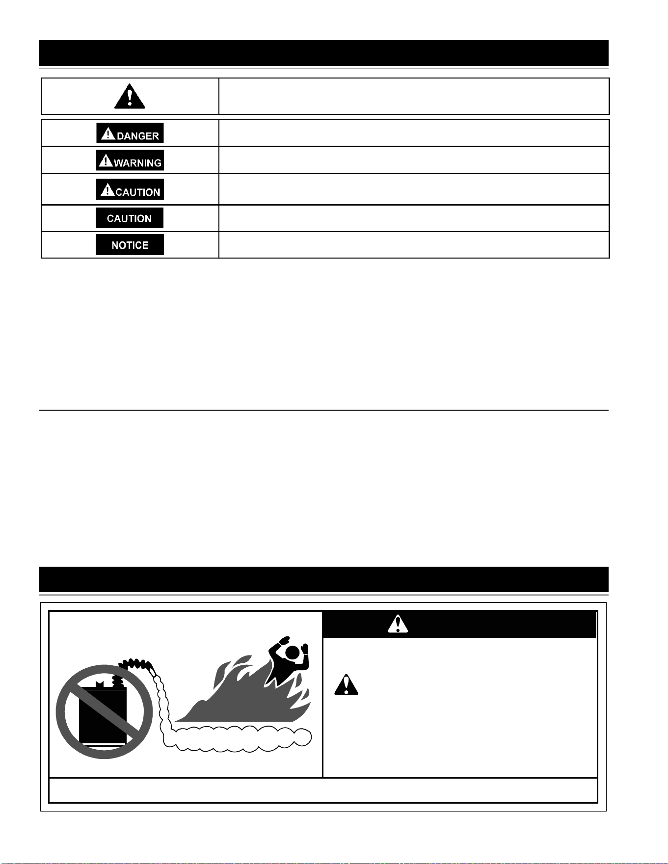
Flammable Vapors
FLAMMABLES
FIRE AND EXPLOSION HAZARD
Can result in serious injury or death
Do not store or use gasoline or other
flammable vapors and liquids in the vicinity of this
or any other appliance. Storage of or use of
gasoline or other flammable vapors or liquids in the
vicinity of this or any other appliance can result in
serious injury or death.
Read and follow water heater warnings and instructions.
WARNING
Your safety and the safety of others is extremely important in the installation, use and servicing of this water heater.
Many safety-related messages and instructions have been provided in this manual and on your own water heater to warn you and others of
a potential injury hazard. Read and obey all safety messages and instructions throughout this manual. It is very important that the meaning
of each safety message is understood by you and others who install, use or service this water heater.
All safety messages will generally tell you about the type of hazard, what can happen if you do not follow the safety message and
how to avoid the risk of injury.
This product is certifi ed to comply with a maximum weighted average of 0.25% lead content as required in some areas.
IMPORTANT DEFINITIONS
• Qualifi ed Technician: A qualifi ed technician must have ability equivalent to a licensed tradesman in the fi elds of plumbing, air supply,
venting, and gas supply, including a thorough understanding of the requirements of the National Fuel Gas Code as it relates to the
installation of gas fi red water heaters. The qualifi ed technician must also be familiar with the design features and use of fl ammable vapor
ignition resistant water heaters, and have a thorough understanding of this instruction manual.
• Service Agency: A service agency also must have ability equivalent to a licensed tradesman in the fi elds of plumbing, air supply, venting
and gas supply, including a thorough understanding of the requirements of the National Fuel Gas Code as it relates to the installation of
gas fi red water heaters. The service agency must also have a thorough understanding of this instruction manual, and be able to perform
repairs strictly in accordance with the service guidelines provided by the manufacturer.
• Gas Supplier: The natural gas or propane utility or service who supplies gas for utilization by the gas burning appliances within this
application. The gas supplier typically has responsibility for the inspection and code approval of gas piping up to and including the natural
gas meter or propane storage tank of a building. Many gas suppliers also offer service and inspection of appliances within the building.
This is the safety alert symbol. It is used to alert you to potential personal injury hazards.
Obey all safety messages that follow this symbol to avoid possible injury or death.
DANGER indicates an imminently hazardous situation which, if not avoided, will
result in death or injury.
WARNING indicates a potentially hazardous situation which, if not avoided, could result
in death or injury.
CAUTION indicates a potentially hazardous situation which, if not avoided, could result
in minor or moderate injury.
CAUTION used without the safety alert symbol indicates a potentially hazardous
situation which, if not avoided, could result in property damage.
NOTICE Indicates information considering important but not hazard related.
SAFE INSTALLATION, USE AND SERVICE
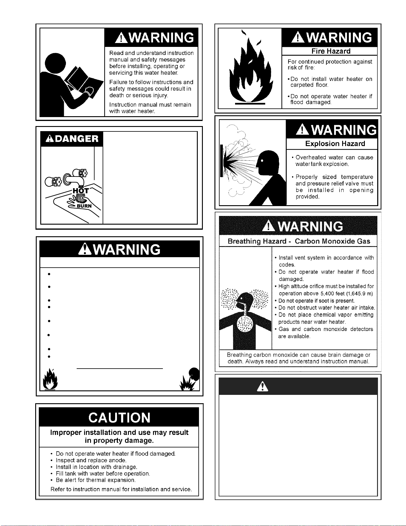
3
Fire or Explosion Hazard
Do not store or use gasoline or other flammable vapors and
liquids in the vicinity of this or any other appliance.
Read instruction manual before
installing, using or servicing
water heater.
Avoid all ignition sources if you smell Natural or LP gas.
Do not expose water heater control to excessive gas
pressure.
Use only gas shown on rating plate unless the water heater
has been properly converted.
Maintain required clearances to combustibles.
Keep ignition sources away from faucets after extended
period of non-use.
Follow conversion instructions listed in manual when
converting to opposite gas.
Do not store or use gasoline or other flammable vapors and
liquids in the vicinity of the water heater air intake.
Water temperature over 125°F
(52°C) can cause servere burns
instantly resulting in severe injury or
death.
Children, the elderly, and the
physically or mentally disabled are at
highest risk for scald injury.
Feel water before bathing or
showering.
Temperature limiting valves are
available.
Read instruction manual for safe
temperature setting.
DANGER
Do not use this water heater with any gas other than the
one listed on the rating plate unless the water heater has
been properly converted.
Refer to the “Gas Conversion” section of this manual to
convert from one gas to another. Failure to use the
correct gas can cause problems which can result in
death, serious bodily injury or property damage. If you
have any questions or doubts, consult your gas supplier
or gas utility company. Water heaters using bottled
propane or liquefied petroleum gas (LPG) are different
from natural gas models. A natural gas water heater will
not function safely on bottled propane or liquefied
petroleum gas (LPG) and a propane gas water heater will
not function safely on natural gas.

4
SAFE INSTALLATION, USE AND SERVICE..................................2
GENERAL SAFETY.....................................................................2-3
TABLE OF CONTENTS ..................................................................4
INTRODUCTION ............................................................................4
Preparing for the New Installation .............................................4
TYPICAL INSTALLATION ............................................................5-6
LOCATING THE NEW WATER HEATER .......................................7
Facts to Consider About Location ..........................................7-8
Insulation Blankets ....................................................................9
INSTALLING THE NEW WATER HEATER ...............................9-20
Water Heater Installation ......................................................9-10
Securing Water Heater to Floor and Wall ................................10
Roof Jack Installation .........................................................11-12
Manufactured Home installed Over Basement or
Crawlspace-Air Intake Through an Outside wall ................12-13
Cutting Opening Through an Outside Wall and
Collar Installation ................................................................13
Cementing PVC, ABS or CPVC Pipe and Fittings ..............13-14
Water Piping ............................................................................14
T & P Valve and Pipe Insulation .........................................14-15
Water Piping Pressure Test .....................................................15
Temperature Pressure Relief Valve ....................................15-16
Filling the Water Heater ...........................................................16
Gas Requirements ..................................................................17
Gas Piping ...............................................................................17
Gas Pressure/Gas Pressure Testing .......................................17
LP Gas Only ............................................................................18
Sediment Traps .......................................................................18
Installation Requirements for Massachusetts ..........................20
INSTALLATION CHECKLIST .......................................................21
GAS CONVERSION ................................................................21-22
LIGHTING INSTRUCTIONS .........................................................23
TEMPERATURE REGULATION ..................................................24
FOR YOUR INFORMATION ....................................................25-26
Start Up Conditions ............................................................25-26
Condensate ........................................................................25
Smoke/Odor .......................................................................25
Thermal Expansion ............................................................25
Strange Sounds ..................................................................25
Operational Conditions ............................................................25
Smelly Water ......................................................................25
“Air” in Hot Water Faucets ..................................................26
Safety Shut Off System ......................................................26
MAINTENANCE OF YOUR WATER HEATER ........................27-31
LEAKAGE CHECKPOINTS ..........................................................32
TROUBLESHOOTING GUIDELINES ......................................33-34
PILOT LIGHT TROUBLESHOOTING CHART .............................35
REPAIR PARTS LIST ...................................................................36
NOTES ....................................................................................37-39
WARRANTY ............................................................................Insert
Thank You for purchasing this water heater. Properly installed and
maintained, it should give you years of trouble free service.
Abbreviations Found In This Instruction Manual:
• CSA - Canadian Standards Association
• ANSI - American National Standards Institute
• NFPA - National Fire Protection Association
• ASME - American Society of Mechanical Engineers
This gas-fired water heater is design certified by CSA
INTERNATIONAL under American National Standard/CSA Standard
for Gas Water Heaters (ANSI Z21.10.1 • CSA 4.1 - current edition).
IMPORTANT: This water heater is shipped from the factory as a
natural gas unit. However, it may be converted to use LP gas. See
the Gas Conversion section for more information.
PREPARING FOR THE INSTALLATION
1. Read the General Safety section (pages 2 & 3) of this manual fi rst and
then the entire manual carefully. If you don’t follow the safety rules,
the water heater will not operate properly. It could cause DEATH,
SERIOUS BODILY INJURY AND/OR PROPERTY DAMAGE.
This manual contains instructions for the installation, operation,
and maintenance of the gas-fi red water heater. It also contains
warnings throughout the manual that you must read and be
aware of. All warnings and all instructions are essential to the
proper operation of the water heater and your safety. Since we
cannot put everything on the fi rst few pages, READ THE ENTIRE
MANUAL BEFORE ATTEMPTING TO INSTALL OR OPERATE
THE WATER HEATER.
2. Instructions to Manufactured Home Manufacturers:
The installation must conform with the Manufactured Home
Construction and Safety Standards Title 24 CFR, Part 3280.
Instruction for replacement installation:
The installation must conform with these instructions and the local
code authority having jurisdiction. In the absence of local codes,
installations shall comply with the National Fuel Gas Code ANSI
Z223.1/NFPA 54. This publication is available from the Canadian
Standards Association, 8501 East Pleasant Valley Rd., Cleveland
Ohio 44131, or The National Fire Protection Association,
1 Batterymarch Park, Quincy, MA 02269.
3. If after reading this manual you have any questions or do not
understand any portion of the instructions, call the local gas utility
or the manufacturer whose name appears on the rating plate.
4. Carefully plan the place where you are going to put the water
heater. Correct combustion, vent action, and vent pipe installation
are very important in preventing death from possible carbon
monoxide poisoning and fi res. See Figures 1 and 2.
Examine the location to ensure the water heater complies with
the “Locating the New Water Heater” section in this manual.
5. For California installation this water heater must be braced,
anchored, or strapped to avoid falling or moving during an
earthquake. See instructions for correct installation procedures.
Instructions may be obtained from California’s Offi ce of the
State Architect, 1102 Q Street, Suite 5100, Sacramento, CA
95811. Instructions can also be downloaded to your computer
at www.dsa.dgs.ca.gov/Pubs.
6. Massachusetts Code requires this water heater to be installed in
accordance with Massachusetts 248-CMR 2.00: State Plumbing
Code and 248-CMR 5.00.
7. Complies with SCAQMD rule #1121 and Districts having equivalent
NOx requirements.
8. Service to the water heater should only be performed by a qualifi ed
technician. Examples of a qualifi ed technician include: licensed
plumbers, authorized gas company personnel, and authorized
service personnel.
INTRODUCTION
TABLE OF CONTENTS
5
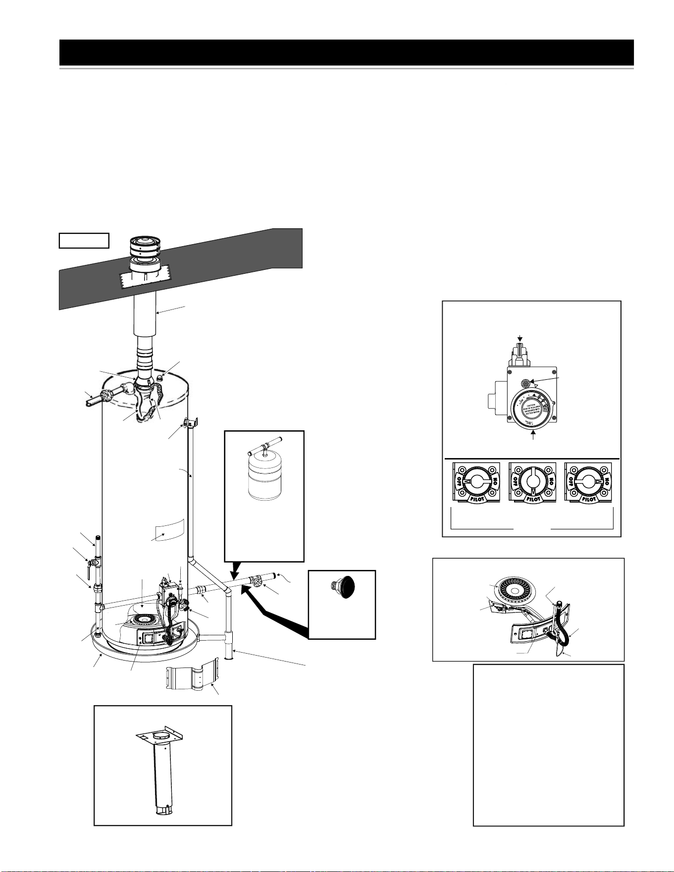
TYPICAL INSTALLATION
A
B
Q
O
C
X
D
DISCHARGE PIPE
(DO NOT CAP
OR PLUG.)
E
F
G
P
S
L
K
M
U
R
H
V
T
I
J
W
A Flue Reducer
B Anode
C Hot Water Outlet
D Insulation
E Gas Supply Piping
F Manual Gas Shut-off Valve
G Ground Joint Union
H Sediment Trap
I Inner Door
Y
GET TO KNOW YOUR WATER HEATER - GAS MODELS
J Outer Door
K Union
L Inlet Water Shut-off Valve
M Cold Water Inlet
N Inlet Dip Tube (Not Shown)
O Temperature-Pressure Relief Valve
P Rating Plate
Q Flue Baffle
S Drain Valve
T Manifold/Burner Assembly
U Flue
V Metal Drain Pan
W Piezo Igniter (bottom, Left-hand
Side of Gas Control Valve/Thermostat)
X Roof Jack *
Air Duct Assembly **
R Gas Control Valve/Thermostat
(T) MANIFOLD/BURNER ASSEMBLY
MANIFOLD
TUBE
IGNITER WIRE
MAIN BURNER
PILOT TUBE
THERMOCOUPLE
MANIFOLD DOOR
INSTALL THERMAL
EXPANSION TANK
IF WATER HEATER
IS INSTALLED IN
A CLOSED WATER
SYSTEM*
VACUUM RELIEF
VALVE*
INSTALL PER
LOCAL CODES
•
INSTALL IN ACCORDANCE
WITH LOCAL CODES.
•
SEDIMENT TRAP AS REQUIRED
BY LOCAL CODES.
• SECURE WATER HEATER TO
FLOOR AND WALL AS DESCRIBED
IN THIS MANUAL.
•
INSTALLATION SHOULD COMPLY
WITH THE INSTRUCTIONS IN THIS
MANUAL.
•
ALL PIPING MATERIALS TO BE
SUPPLIED BY CUSTOMERS.
DRAIN LINE MUST PASS
THROUGH THE STRUCTURAL
FLOOR AND DISCHARGE
EXTERNAL TO THE BUILDING.
IN COLD CLIMATES, IT IS
RECOMMENDED THAT THE
DRAIN LINE BE TERMINATED
AT AN ADEQUATE DRAIN
INSIDE THE BUILDING.
* CERTIFIED ROOF JACK FROM THE MANUFACTURER
MUST BE ORDERED SEPARATELY ACCORDING TO
LENGTH NEEDED. SEE ROOF JACK INSTALLATION
SECTION IN THIS MANUAL FOR INSTRUCTIONS AND
PART NUMBERS.
**AIR DUCT ASSEMBLY IS FURNISHED WITH THE WATER
HEATER. ANY ADDITIONAL PLUMBING AND VENTING
MATERIALS ARE NOT FURNISHED
PILOT
(Y) AIR DUCT ASSEMBLY*
GAS CONTROL KNOB
WATER TEMPERATURE DIAL
(ADJUSTING DIAL)
TOP VIEW
“OFF”
POSITION
“PILOT”
POSITION
“ON”
POSITION
(R) GAS CONTROL VALVE/
THERMOSTAT: WHITE-RODGERS
CONVERSION
FITTING
FIGURE 1.
Figure 1.
6
This appliance has been design certifi ed as complying with American
National Standard/CSA Standard ANSI Z21.10.1 • CSA 4. 1 for water
heaters and is considered suitable for:
Water (Potable) Heating: All models are considered suitable for water
(potable) heating, but not suitable for space heating applications.
HOTTER WATER CAN SCALD:
Water heaters are intended to produce hot water. Water heated to
a temperature which will satisfy clothes washing, dish washing, and
other sanitizing needs can scald and permanently injure you upon
contact. Some people are more likely to be permanently injured by
hot water than others. These include the elderly, children, the infi rm,
or physically/mentally handicapped. If anyone using hot water in your
home fi ts into one of these groups or if there is a local code or state
law requiring a certain temperature water at the hot water tap, then
you must take special precautions. In addition to using the lowest
possible temperature setting that satisfi es your hot water needs,
a means such as a *mixing valve should be used at the hot water
taps used by these people or at the water heater. Mixing valves are
available at plumbing supply or hardware stores. Consult a Qualifi ed
Installer or Service Agency. Follow mixing valve manufacturer’s
instructions for installation of the valves. Before changing the factory
setting on the thermostat, read the “Temperature Regulation” section
in this manual. See Figure 32.
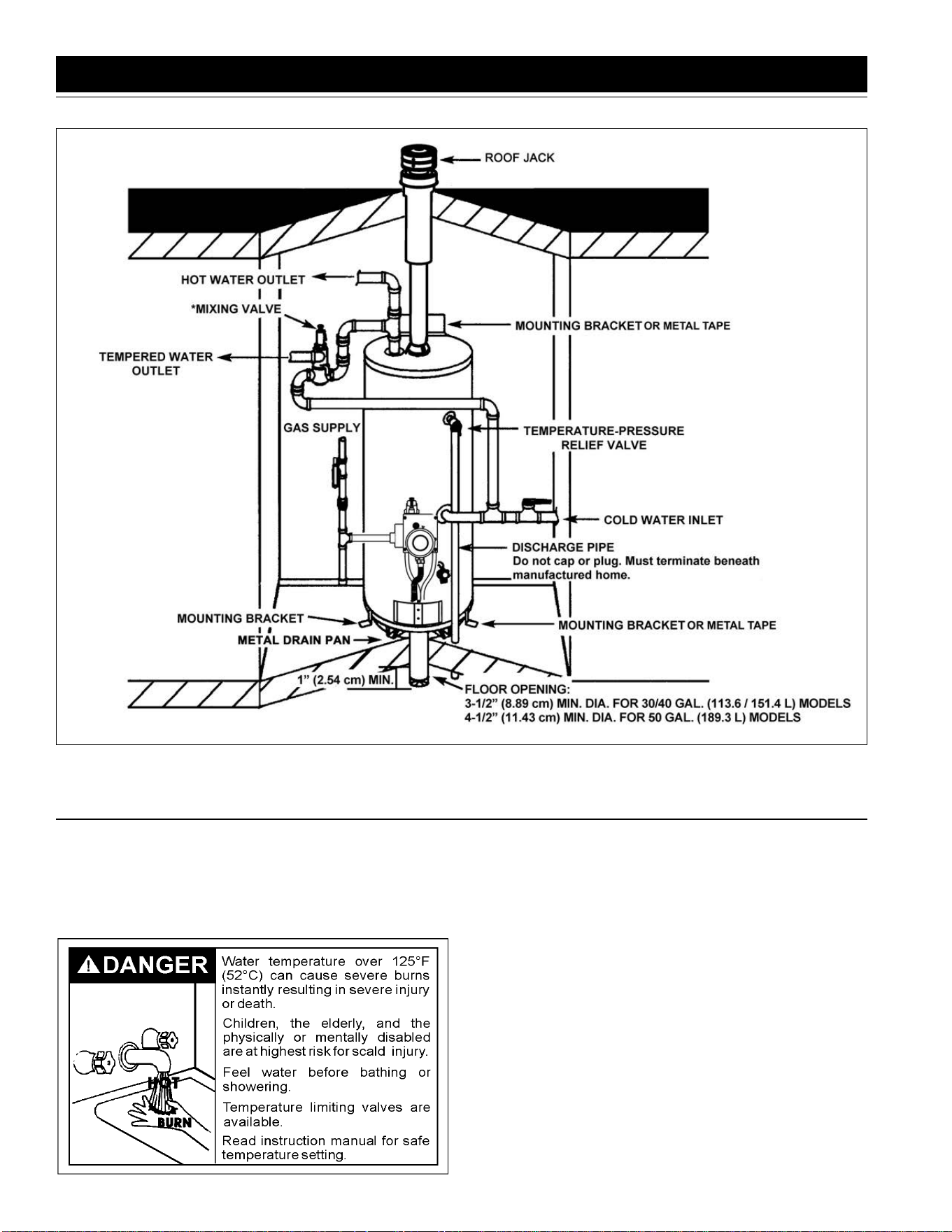
TYPICAL INSTALLATION
Figure 2.
* MIXING VALVE USAGE
7
FACTS TO CONSIDER ABOUT THE LOCATION
Whether replacing an old water heater or putting the water heater
in a new location, the following critical points must be observed.
This manufactured home gas-fi red water heater is for use in a
manufactured home. You should carefully choose an indoor location
for the new water heater, because the placement is a very important
consideration for the safety of your occupants in the building and
for the most economical use of the appliance. This water heater
is for use only in a manufactured home and not intended for
outdoor installation.
This water heater has been designed and certifi ed as a direct vent
(sealed combustion) unit and no draft diverter is to be used.
Minimum clearances between the water heater and combustible
surfaces are stated on the label adjacent to the gas control
valve/thermostat. The water heater is certified for installation
on a combustible floor. Minimum vent clearances: 6” (15.2 cm).
Provide 24” (61 cm) front clearance for servicing and adequate
clearance between the jacket top and ceiling for servicing the fl ue area.
Roof jack: surface of outer pipe has a minimum clearance of 0” (0 cm).
The combustion and ventilation air fl ow must not be obstructed.
Combustion air shall not be supplied from occupied spaces. Instead,
combustion air must be supplied from outside the manufactured
home by way of the furnished air intake duct assembly. The air
intake duct assembly is 3” (7.62 cm) in diameter for 30 and 40 Gallon
models or 4” (10.2 cm) in diameter for 50 Gallon models.
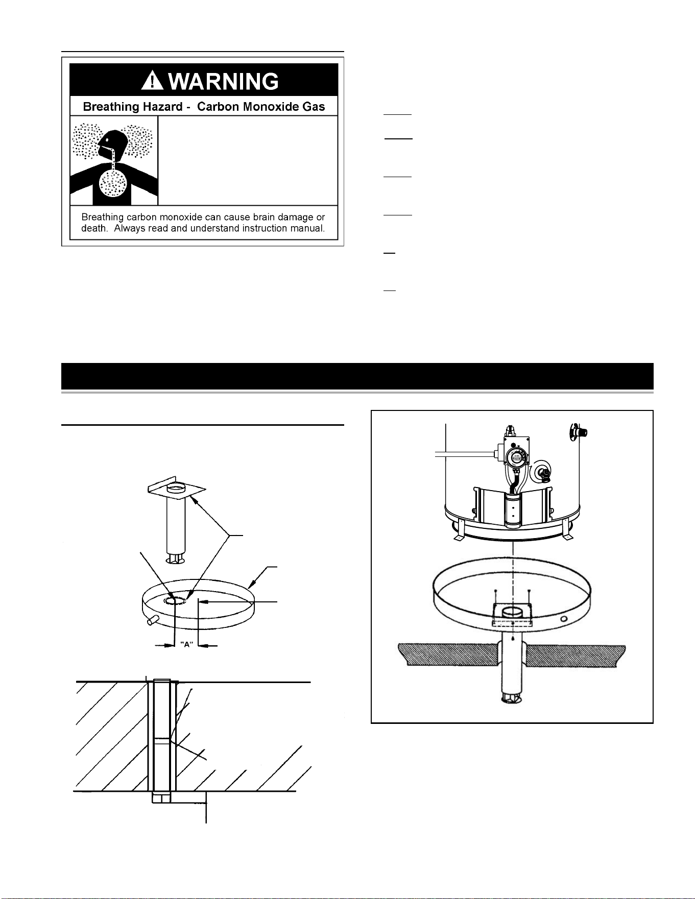
A 3-1/2” (8.89 cm) diameter fl oor opening beneath the water heater
is required to accommodate the air intake duct assembly for 30
and 40 Gallon models. A 4-1/2” (11.43 cm) diameter fl oor opening
is required beneath the water heater for 50 Gallon models. The
weight of the water heater itself seals the water heater to the air
intake duct assembly.
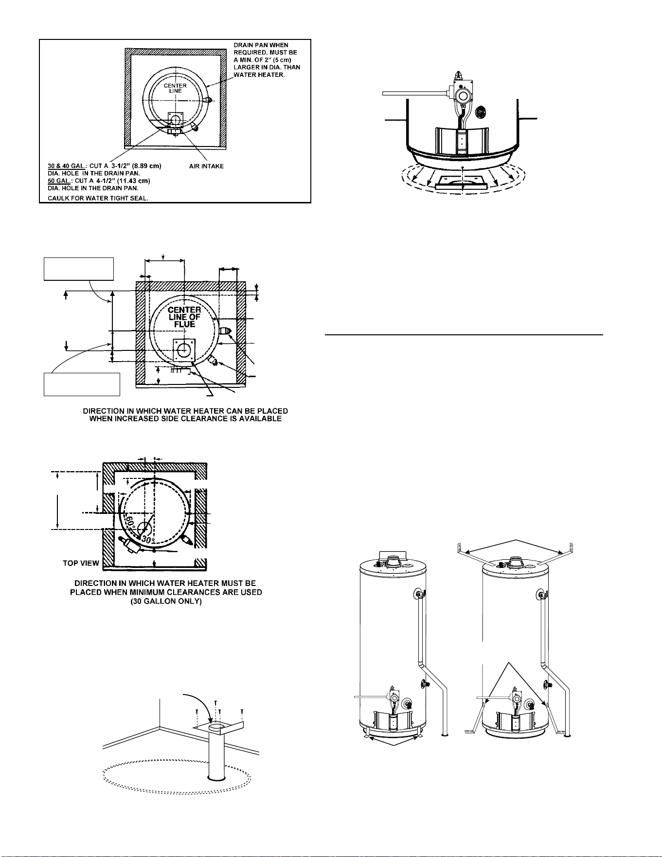
When a manufactured home is skirted, an air intake opening with
a minimum free area of 32 square inches (206.45 cm²) must be
provided in the skirt. If the opening is covered by louvers or screen,
the total free area must be 32 square inches (206.45 cm²). Other gas
fi red appliance in the home will require additional free air openings;
consult these manufacturers for correct sizing. See Figure 3.
FIGURE 3.
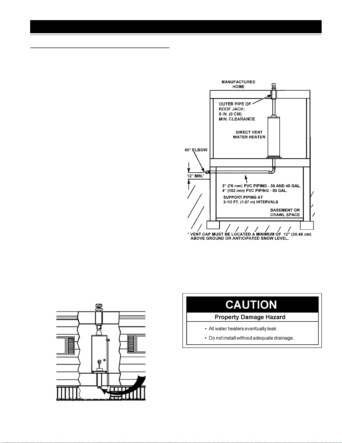
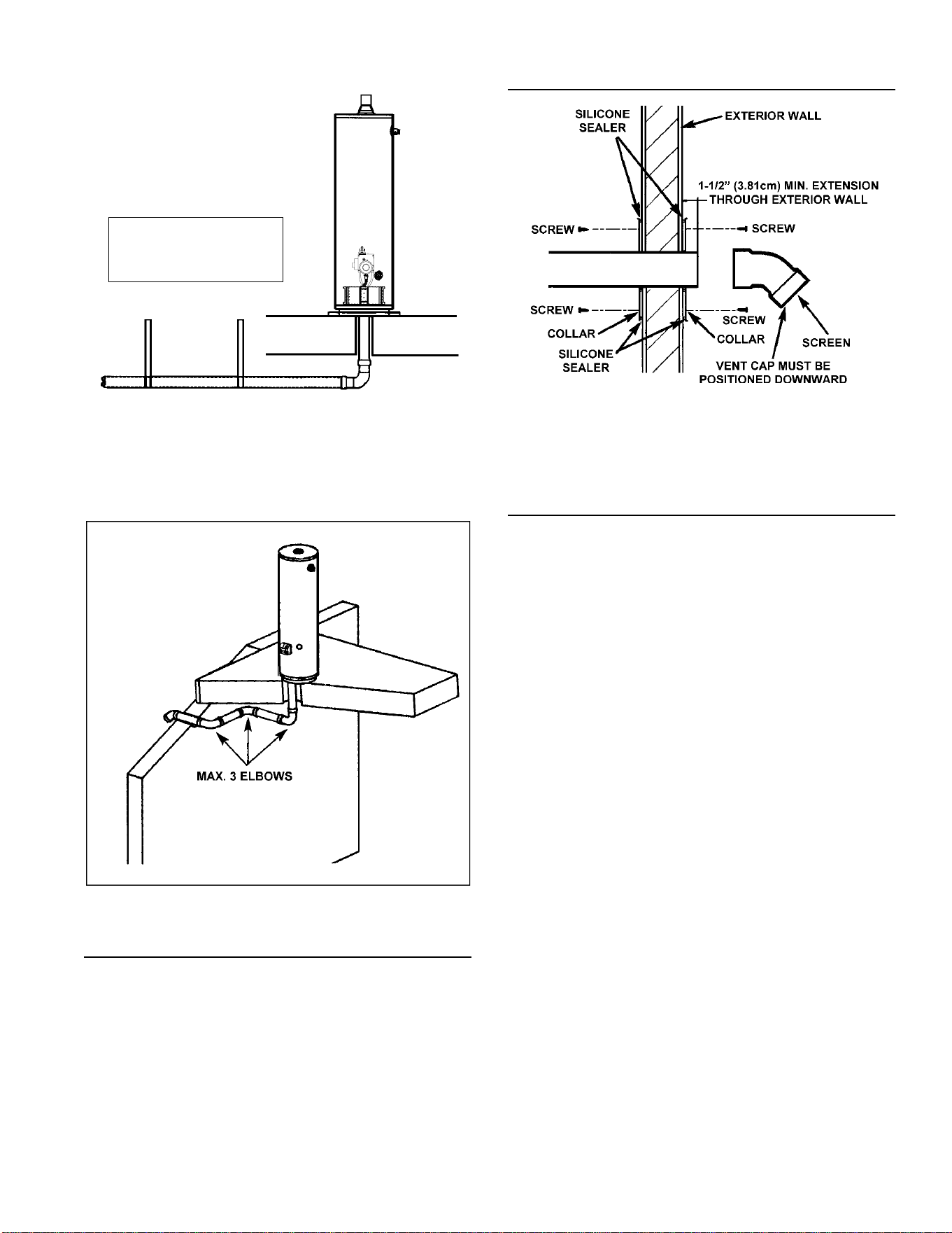
If the manufactured home is installed over a basement or crawlspace,
combustion air must be supplied from outside the manufactured
LOCATING THE NEW WATER HEATER
home. The combustion air intake piping can be 3” (76 mm) PVC for
30 and 40 gallon models and 4” (102 mm) PVC for 50 Gallon models.
The air intake piping cannot exceed the lengths shown in Table 1 (page
12), including vertical and horizontal runs, or have more than 3 elbows.
All horizontal runs require adequate support at 3-1/2 foot (106.68 cm)
intervals. See Figure 4.
FIGURE 4.
The water heater should be secured to the fl oor and to the wall of the
enclosure with the mounting brackets provided. For bracket location,
refer to Securing Water Heater to Floor and Wall.
Installation of the water heater must be accomplished in such a
manner that if the tank or any connections should leak, the fl ow
will not cause damage to the structure. For this reason, it is not
advisable to install the water heater in an attic or upper fl oor. When
such locations cannot be avoided, a suitable metal drain pan should
be installed under the water heater. Metal drain pans are available at
your local hardware store. Such a drain pan must have a minimum
length and width of at least 2 inches (51 mm) greater than the water
heater dimensions and must be piped to an adequate drain. The pan
must not restrict combustion air fl ow. When a drain pan is required,
see installation instructions on page 9.
Water heater life depends upon water quality, water pressure and
8
the environment in which the water heater is installed. Water heaters
are sometimes installed in locations where leakage may result in
property damage, even with the use of a metal drain pan piped to a
drain. However, unanticipated damage can be reduced or prevented
by a leak detector or water shut-off device used in conjunction with
a piped drain pan. These devices are available from some plumbing
supply wholesalers and retailers, and detect and react to leakage
in various ways:
• Sensors mounted in the drain pan that trigger an alarm or turn off
the incoming water to the water heater when leakage is detected.
• Sensors mounted in the drain pan that turn off the water supply
to the entire home when water is detected in the drain pan.
• Water supply shut-off devices that activate based on the water
pressure differential between the cold water and hot water pipes
connected to the water heater.
• Devices that will turn off the gas supply to a gas water heater
while at the same time shutting off its water supply.
INSTALLATIONS IN AREAS WHERE FLAMMABLE LIQUIDS
(VAPORS) ARE LIKELY TO BE PRESENT OR STORED
(GARAGES, STORAGE AND UTILITY AREAS, ETC.): Flammable
liquids (such as gasoline, solvents, propane [LP or butane, etc.] and
other substances such as adhesives, etc.) emit fl ammable vapors
which can be ignited by a gas water heater’s pilot light or main burner.
The resulting fl ashback and fi re can cause death or serious burns
to anyone in the area, as well as property damage. Gasoline and
other fl ammable substances should never be stored or used in the
same room or area containing a gas water heater or other open
fl ame or spark producing appliance. Additionally, do not store or use
gasoline or other fl ammable vapors and liquids in the vicinity of the
water heater air intake. NOTE: Flammable vapors may be drawn
by air currents from other areas of the structure to the appliance.
Also, the water heater must be located and/or protected so it is not
subject to physical damage by a moving vehicle.
This water heater must not be installed directly on carpeting.
Carpeting must be protected by metal or wood panel beneath the
appliance extending beyond the full width and depth of the appliance
by at least 3 inches (76.2 mm) in any direction, or if the appliance is
installed in an alcove or closet, the entire fl oor must be covered by
the panel. Failure to heed this warning may result in a fi re hazard.
IMPORTANT: Keep combustibles such as boxes, magazines,
clothes, etc., away from the water heater area.
A gas water heater cannot operate properly without the correct
amount of air for combustion. Provide ventilation and combustion
air by means of an air intake duct assembly as stated in “Water
Heater Installation”. Never obstruct the fl ow of ventilation air. If you
have any doubts or questions at all, call your gas supplier. Failure
to provide the proper amount of combustion air can result in a fi re or
explosion and cause death, serious bodily injury, or property damage.
If this water heater will be used in beauty shops, barber shops,
cleaning establishments, or self-service laundries with dry cleaning
equipment, it is imperative that the water heater or water heaters
be installed so that combustion and ventilation air be taken from
outside these areas.
Propellants of aerosol sprays and volatile compounds, (cleaners,
chlorine based chemicals, refrigerants, etc.) in addition to being
highly fl ammable in many cases, will also change to corrosive
hydrochloric acid when exposed to the combustion products of
the water heater. The results can be hazardous and also cause
product failure.
9
• Do not obstruct water heater air
intake with insulating blanket.
• Gas and carbon monoxide detec-
tors are available.
• Install water heater in accordance
with the instruction manual.
INSULATION BLANKETS
Insulation blankets are available to the general public for external
use on gas water heaters but are not necessary with these products.
The purpose of an insulation blanket is to reduce the standby heat
loss encountered with storage tank heaters. Your water heater
meets or exceeds the National Appliance Energy Conversation Act
standards with respect to insulation and standby loss requirements,
making an insulation blanket unnecessary.
Should you choose to apply an insulation blanket to this heater, you
should follow these instructions (For identifi cation of components
mentioned below, see Figure 1). Failure to follow these instructions
can restrict the air fl ow required for proper combustion, potentially
resulting in fi re, asphyxiation, serious personal injury or death.
• Do not apply insulation to the top of the water heater, as this will
interfere with safe operation of the draft hood.
• Do not cover the outer door, the gas control valve/thermostat or
the temperature & pressure relief valve.
• Do not allow insulation to come within 2” (50.8 mm) of the fl oor to
prevent blockage of combustion air fl ow to the burner.
• Do not cover the instruction manual. Keep it on the side of the
water heater or nearby for future reference.
• Do obtain new warning and instruction labels from the manufacturer
for placement on the blanket directly over the existing labels.
• Do inspect the insulation blanket frequently to make certain it
does not sag, thereby obstructing combustion air fl ow.
INSTALLING THE NEW WATER HEATER
WATER HEATER INSTALLATION
1. To locate the position of the 3-1/2” (8.9 cm) or 4-1/2” (11.4 cm)
hole to be cut in the fl oor, see Figures 5 and 6.
METAL
DRAIN
PAN
“A” = 4-3/8” (11.11 cm) 30 GAL.
“A” = 5-3/8” (13.65 cm) 40 GAL.
“A” = 5-3/8” (13.65 cm) 50 GAL.
CENTERLINE
OF WATER
HEATER
3-1/2” (8.89cm) DIA. HOLE
(30 & 40 GALLON)
4-1/2” (11.43cm) DIA. HOLE
(50 GALLON)
APPLY 4” (10.2 cm) OR
5” (12.7 cm) CIRCLE OF
SILICONE AROUND THE
BOTTOM OF PLATE
FOR PROPER WATER
TIGHT SEALING
AFTER ADJUSTING LENGTH OF DUCT
ASSEMBLY AS SHOWN ABOVE, CAULK
ALL AROUND PIPING WITH RTV SILICON
SEALANT FOR AIR TIGHT SEAL BEFORE
INSTALLING IN FLOOR CAVITY.
ALTERNATIVE: USE 2” (5 cm) WIDE BAND
OF .002 ALUMINUM TAPE.
SCREWS (2)
2-1/2” (6.35 cm) MIN.
BOTTOM OF FLOOR
FIGURE 5.
FIGURE 6.
2. If you have found that the water heater is being installed in an
area which, if the water heater was to leak, would cause damage
and have elected to install a metal drain pan, refer to Figures 7, 8
and 9 on page 10. If you are not installing a drain pan, go directly
to the next step.
NOTE: Clearances from combustible or non combustible surface to
jacket will change template dimensions.
10
FIGURE 7.
4” (10.16 cm) MIN. - 30 GAL.
0” MIN. - 40 & 50 GAL.
0” MIN.
BASE DIAMETER
14” (35.56 cm) 30 GAL.
16” (40.64 cm) 40 GAL.
16” (40.64 cm) 50 GAL.
JACKET DIAMETER
18” (45.72 cm) 30 GAL.
20” (50.8 cm) 40 GAL.
22” (55.88 cm) 50 GAL.
30 GAL. T&P LOC.
40 & 50 GAL.
T&P LOC.
GAS CONTROL VALVE /
THERMOSTAT
AIR INTAKE
4” (10.2 cm) MIN.
2-1/2” (6.35cm)
4-13/32” (11.2 cm) - 30 GAL.
5-13/32” (13.7 cm) - 40 GAL.
5-13/32” (13.7 cm) - 50 GAL.
30 GALLON:
13-13/32” (34 cm) MIN.
40 GALLON:
15-13/32” (39.1 cm) MIN.
50 GALLON:
16-13/32” (41.7 cm) MIN.
9” (22.86 cm) MIN. - 30 GAL.
10” (25.4 cm) MIN. - 40 GAL.
11” (27.9 cm) MIN. - 50 GAL.
0” MIN.
9” (22.86 cm) MIN. - 30 GAL.
10” (25.4 cm) MIN. - 40 GAL.
11” (27.9 cm) MIN. - 50 GAL.
FIGURE 8.
2-7/32”
(5.59 cm)
GAS CONTROL VALVE / THERMOSTAT
4”
(10.16 cm)
BASE DIA. - 14”
(35.56 cm)
JACKET DIA. - 18”
(45.72 cm)
12-13/16”
(32.54 cm)
9”
(22.86 cm)
0” MIN.
0” MIN.
0” MIN.
3-13/16”
(9.68 cm)
FIGURE 9.
3. Insert the duct assembly as shown in Figure 10 with lip facing
forward, and using only nails, secure the duct assembly to the
fl oor.
FRONT
APPLY 4” (10.16 cm) OR 5” (12.7 cm)
CIRCLE OF SILICONE AROUND OPENING
FOR AIR TIGHT SEAL.
FIGURE 10.
4. Set the water heater in place against the lip of the duct assembly
as shown in Figure 11.
FIGURE 11.
5. Secure the water heater to the duct assembly using the screw
provided.
NOTE: See pages 12 and 13 for installing an air intake through
an outside wall when the manufactured home is located over a
basement or crawl space.
SECURING WATER HEATER TO FLOOR AND WALL
(USE METHOD A OR B)
The water heater must be secured to the fl oor and to the wall of the
enclosure.
METHOD A: use the three mounting brackets and screws packaged
in the carton with the water heater. The two small brackets are used to
attach the water heater to the fl oor and the one large bracket is used
to secure the top of the water heater to the wall.
METHOD B: use metal tape also called “plumbers tape” to secure the
water heater to the enclosure. See the fi gure below as reference for
attaching the tape.
Because of installation variances, these brackets can be located at
any points around the circumference of the jacket. When the bracket
locations are determined, use a 1/8 inch SAE drill bit to set a pattern.
Drill only through the outer jacket of the water heater. Then using the
screws provided, secure the bracket to the water heater, fl oor and
wall. See Figure 12.
ONE LARGE MOUNTING
BRACKET AT TOP
TWO SMALL MOUNTING
BRACKETS AT BOTTOM
TWO STRAPS OF METAL
TAPE AT THE TOP
TWO STRAPS OF METAL
TAPE AT THE BOTTOM
METHOD A METHOD B
FIGURE 12.
11
ROOF JACK INSTALLATION
ROOF JACK KIT MODELS VENT KIT- 12 INCH (9002964005), VENT KIT - 32 INCH (9002965005),
VENT KIT - 60 INCH (9002966005) AND VENT KIT - 95 INCH (9002967005)
VENT KIT / 95” (241.3 cm)
VENT KIT / 60”
(152.4 cm)
VENT KIT / 32” (81.28 cm)
VENT KIT / 12” (30.48 cm)
95” (241.3 cm) MAX.
36” (91.4 cm) MIN.
60” (152.4 cm) MAX.
32” (81.28 cm) MIN.
32” (81.28 cm) MAX.
18” (45.72 cm) MIN.
12” (30.48 cm) MAX.
2” (5 cm) MIN. 2” (5 cm) MIN. 2” (5 cm) MIN. 2” (5 cm) MIN.
136” (345.44 cm) MAX.
55” (139.7 cm) MIN.
100” (254 cm) MAX.
40” (101.6 cm) MIN.
72” (182.88 cm) MAX.
25” (63.5 cm) MIN.
52” (132.08 cm) MAX.
18” (45.72 cm) MIN.
23” (58.42 cm) MAX.
ROOF JACK: SURFACE OF OUTER PIPE
HAS A MINIMUM CLEARANCE OF 0” (0 CM).
INLET VENT: SURFACE OF PIPE HAS MINIMUM CLEARANCE OF 0” (0 CM)
FIGURE 13.
A certifi ed roof jack (vent kit) from the manufacturer must be
installed with the water heaters covered by this manual. Roof jack
kits are ordered separately. See Figure 13 to determine which roof
jack is needed for the installation.
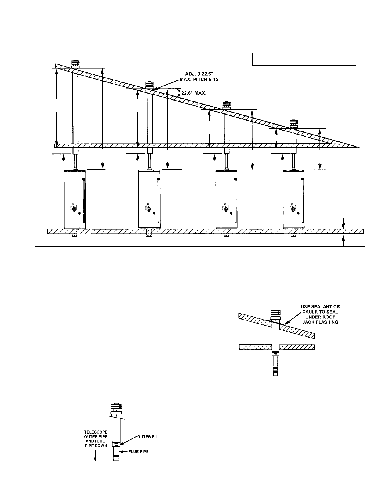
NOTE: An optional Roof jack Extension Pipe (9002588005) is required
when the roof pitch is 5-1/2” (14 cm) or greater, or where local codes
require the roof jack cap (outlet) to terminate above the peak of the roof.
IMPORTANT: DO NOT common vent this water heater with any other
appliance.
1. Cut a 5-1/2” (14 cm) diameter hole through the roof and ceiling
directly in line with the fl ue connection on top of the water heater.
For a sloped roof, the roof hole may have to be enlarged to allow
the roof jack to be installed vertically.
2. Telescope down the fl ue pipe in the roof jack assembly to a length
that will project at least 6” (15.24 cm) below the fi nished ceiling
before installing the roof jack assembly.
NOTE: Flue pipe joints have silicone seals that must remain in place.
A soapy water solution sprayed around the seal area will enable the
fl ue pipe and outer pipe below to telescope more freely.
3. Telescope down the outer pipe of the roof jack assembly to a length
that will project at least 2” (5 cm) below the fi nished ceiling before
installing the roof jack assembly. See Figure 14.
FIGURE 14.
4. Ease the roof jack assembly through the roof and ceiling openings. The
roof jack fl ashing tilts up to 22.6° degrees for use on a sloping roof.
5. Use sealant or caulk on the roof to seal under fl ashing of the roof
jack assembly. Use roof nails or screws on wood construction or
sheet metal screws on metal roofs (nails and screws not provided).
See Figure 15.
FIGURE 15.
Continued on the next page.
12
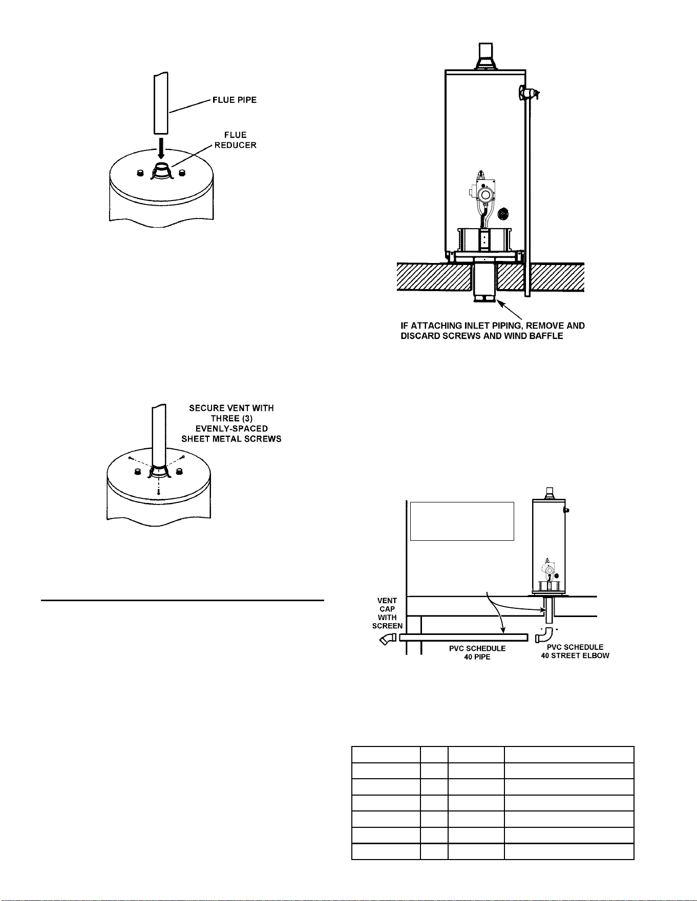
6. Extend the fl ue pipe downward until it is close to the fl ue reducer.
See Figure 16.
FIGURE 16.
7. Fit the bottom opening of the pipe over the top opening of the
fl ue reducer. See Figure 17. Ensure that there is no gap and
that the seal is complete.
8. Secure the fl ue pipe to the reducer with three (3) evenly-spaced
sheet metal screws (Figure 17). Do not leave any open holes
in the fl ue reducer or fl ue pipe.
NOTE: All joints for vent piping between roof jack and water
heater are sealed from the manufacturer. No additional sealing
of vent pipe is necessary.
FIGURE 17.
MANUFACTURED HOME INSTALLED OVER
BASEMENT OR CRAWL SPACE -
AIR INTAKE THROUGH AN OUTSIDE WALL
ALL 30 AND 40 GALLON MODELS
3” (76 mm) PVC Schedule 40 intake air vent piping:
Optional Kit No. 9002986005 contains a 3” (76 mm) PVC Schedule
40-45° vent cap with screen and two 3” (76 mm) wall collars.
ALL 50 GALLON MODELS
4” (102 mm) PVC Schedule 40 intake air vent piping:
Optional Kit no. 9002987005 contains a 4” (102 mm) PVC Schedule
40-45° vent cap with screen and two 4” (102 mm) wall collars.
ALL MODELS
1. PVC, ABS or CPVC Schedule 40 piping and fittings are
acceptable materials for the air intake vent system.
2. The intake air vent system must terminate horizontally to the outdoors.
3. Remove the screws which attach the wind baffl e to the existing
metal air intake vent pipe underneath the home. Discard the wind
baffl e and screws. See Figure 18.
FIGURE 18.
4. Attach a 3” (76 mm) or 4” (102 mm) PVC street elbow to the metal
air intake vent using 3 sheet metal screws. Continue PVC piping
to outside wall and terminate with vent cap and screen. See
Figure 19 and Table 1.
3” (76 mm) size - 30 and 40 gallon models.
4” (102 mm) size - 50 gallon models.
See pages 13 and 14 for cementing instructions
SEE MAXIMUM
COMBINED
LENGTHS IN
TABLE 1.
SLOPE INLET PIPING
DOWNWARD TOWARD
VENT CAP TO PREVENT
CONDENSATION BUILDUP.
FIGURE 19.
NOTE: Vent cap must be located a minimum of 12” (30.48 cm) above
the ground or anticipated snow level.
TABLE 1: AIR INTAKE VENT PIPING REQUIREMENTS
Water Heater Gas
Vent
Dia.
Do Not Exceed:
30 Gallon NAT 3” (76mm) 17 ft. (5.18 m) length; 3 elbows
30 Gallon LP 3” (76mm) 12 ft. (3.66 m) length; 3 elbows
40 Gallon NAT 3” (76mm) 30 ft. (9.1 m) length; 3 elbows
40 Gallon LP 3” (76mm) 20 ft. (6.1 m) length; 3 elbows
50 Gallon NAT 4” (102mm) 30 ft. (9.1 m) length; 3 elbows
50 Gallon LP 4” (102mm) 30 ft. (9.1 m) length; 3 elbows
13
5. Vertical and horizontal runs must be securely supported at 3-1/2
foot (1.06 m) intervals. See Figure 20.
SLOPE INLET PIPING
DOWNWARD TOWARD
VENT CAP TO PREVENT
CONDENSATION BUILDUP.
FIGURE 20.
6. The intake air vent piping can be installed with no more than 3
elbows. See Figure 21.
FIGURE 21.
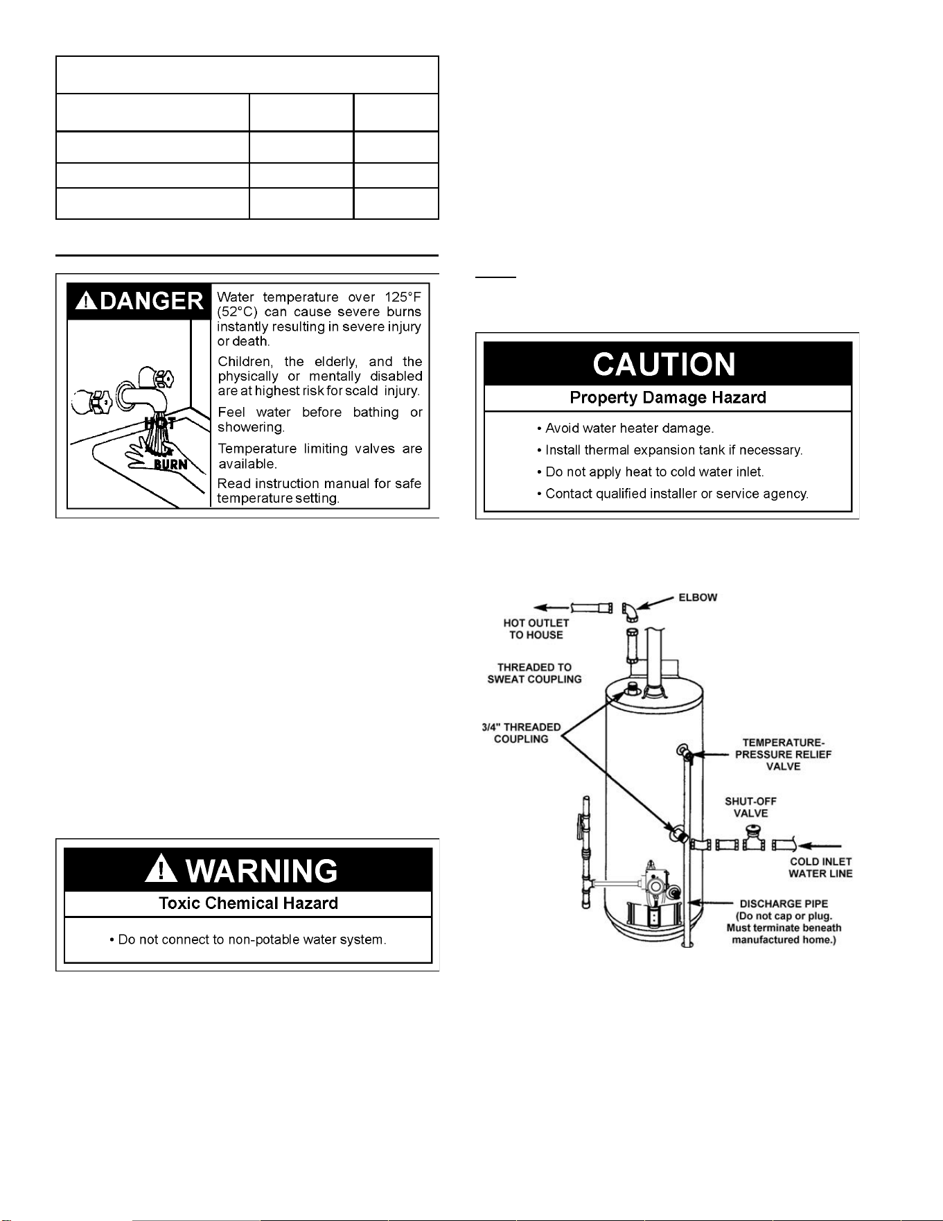
CUTTING OPENING THROUGH AN OUTSIDE WALL
AND COLLAR INSTALLATION
Determine the location for the opening in the wall. For a 30 or 40
gallon model, cut a 3-3/4” (9.5 cm) hole through the outside wall. For
a 50 Gallon model, cut a 4-3/4” (12 cm) hole through the outside wall.
The 3” (76 mm) or 4” (102 mm) PVC, ABS or CPVC Schedule 40
vent pipe can be run from the water heater through the wall or from
the wall to the water heater, whichever is most convenient. The vent
pipe must extend a minimum of 1-1/2” (3.81 cm) through the exterior
wall. Note that the inside collar must be slipped over the vent piping
before locating the pipe through the wall. Before securing the inside
and outside collars to the wall, use a silicone sealer between pipe
and opening to ensure a water and air tight seal. See Figure 22.
INSTALLATION SHOWING USE
OF PVC, ABS OR CPVC PIPE
FIGURE 22.
NOTE: Wall collars are for aesthetic purposes and are not required
for the heater to operate.
CEMENTING PVC, ABS OR CPVC PIPE AND FITTINGS
Read and observe all safety information printed on primer, cleaner,
and cement containers.
Primer, cleaner, and cements are extremely fl ammable. They are
harmful or fatal if swallowed. The vapors are harmful. They may
irritate eyes and skin and can be absorbed through the skin.
Always store primer, cleaner, and cements in cool, dry, well ventilated
places. Keep containers closed. Use them in well ventilated areas.
Wear impervious clothing while handling. Do not smoke, eat, or drink
while handling. Wash thoroughly after handling and before eating.
Wear eye protection when handling. If swallowed, drink water, do
not induce vomiting, and call a physician or poison control center
immediately. If inhaled, get fresh air and seek medical attention if ill
feelings persist. In case of eye and skin contact, immediately fl ush
with plenty of water for 15 minutes and seek medical attention if
irritation persists. KEEP OUT OF REACH OF CHILDREN.
All primers, cleaners, and cements must meet all local codes and
applicable standards of the American Society For Testing Materials
Standards.
Before using primers, cleaners and cements, stir or shake, making sure
contents are liquid. Do not use if found to be lumpy or jelly-like.
1. Cut pipe ends squarely removing all burrs and dirt.
2. Dry fi t pipe and fi ttings to be connected for proper fi t.
3. Clean pipe and fi tting with primer/cleaner.
4. Apply a thin coat of cement to fi tting, avoiding puddling inside.
5. Apply a liberal coat of cement to pipe, leaving no voids.
6. QUICKLY assemble parts while cement is fl uid! If you wait too
long, recoat pipes.
7. Push pipe completely into socket of fi tting, turning as it goes until
it bottoms.
8. Hold pipe and fi tting together for 30 seconds. Then carefully clean
off excess with a cloth. Allow connections a suffi cient time to cure
before disturbing.
9. Remember that vent pipes must be adequately and securely
supported.
14
TABLE 2: APPROX. SETTING TIME FOR 2-1/2” (63.5mm)
TO 4” (102mm) PIPE JOINTS
MOVEMENT
OF JOINT
COMPLETE
SET
90°F (32.2°C) TO 150°F (65.6°C) 3/4HR. 8 HRS.
50°F (10°C) TO 90°F (32.2°C) 1 HR. 15 HRS.
0°F (-17.77°C) TO 50°F (10°C) 1-1/3 HR. 18 HRS.
WATER PIPING
HOTTER WATER CAN SCALD:
Water heaters are intended to produce hot water. Water heated to
a temperature which will satisfy space heating, clothes washing,
dish washing, cleaning and other sanitizing needs can scald and
permanently injure you upon contact. Some people are more likely
to be permanently injured by hot water than others. These include
the elderly, children, the infi rm, or physically/mentally handicapped.
If anyone using hot water in your home fi ts into one of these groups
or if there is a local code or state law requiring a certain temperature
water at the hot water tap, then you must take special precautions. In
addition to using the lowest possible temperature setting that satisfi es
your hot water needs, a means such as a mixing valve should be used
at the hot water taps used by these people or at the water heater.
See Figure 2. Valves for reducing point of use temperature by mixing
cold and hot water are also available. Consult a Qualifi ed Installer or
Service Agency. Follow manufacturer’s instructions for installation
of the valves. Before changing the factory setting on the thermostat,
read the “Temperature Regulation” section in this manual.
This water heater shall not be connected to any heating systems or
component(s) used with a non-potable water heating appliance.
Toxic chemicals, such as those used for boiler treatment shall not
be introduced into this system.
As water is heated, it expands (thermal expansion). In a closed
system, the volume of water will grow. As the volume of water grows,
there will be a corresponding increase in water pressure due to
thermal expansion. Thermal expansion can cause premature tank
failure (leakage). This type of failure is not covered under the limited
warranty. Thermal expansion can also cause intermittent temperature-
pressure relief valve operation: water discharged from the valve due
to excessive pressure build up. The temperature-pressure relief valve
is not intended for the constant relief of thermal expansion. This
condition is not covered under the limited warranty.
A properly-sized thermal expansion tank should be installed on all
closed systems to control the harmful effects of thermal expansion.
Contact a plumbing service agency or your retail supplier regarding
the installation of a thermal expansion tank.
Also, the water supply pressure should not exceed 80 PSI (551.58 kPa).
If this occurs, a pressure reducing valve with a bypass should be installed
in the cold water inlet line. This should be placed on the supply to the entire
house in order to maintain equal hot and cold water pressures.
NOTE: To protect against untimely corrosion of hot and cold
water fi ttings, it is strongly recommended that dielectric unions
or couplings be installed on this water heater when connected
to copper pipe.
Figure 23 shows the typical attachment of the water piping to the
water heater. The water heater is equipped with 3/4 inch NPT water
connections.
FIGURE 23.
15
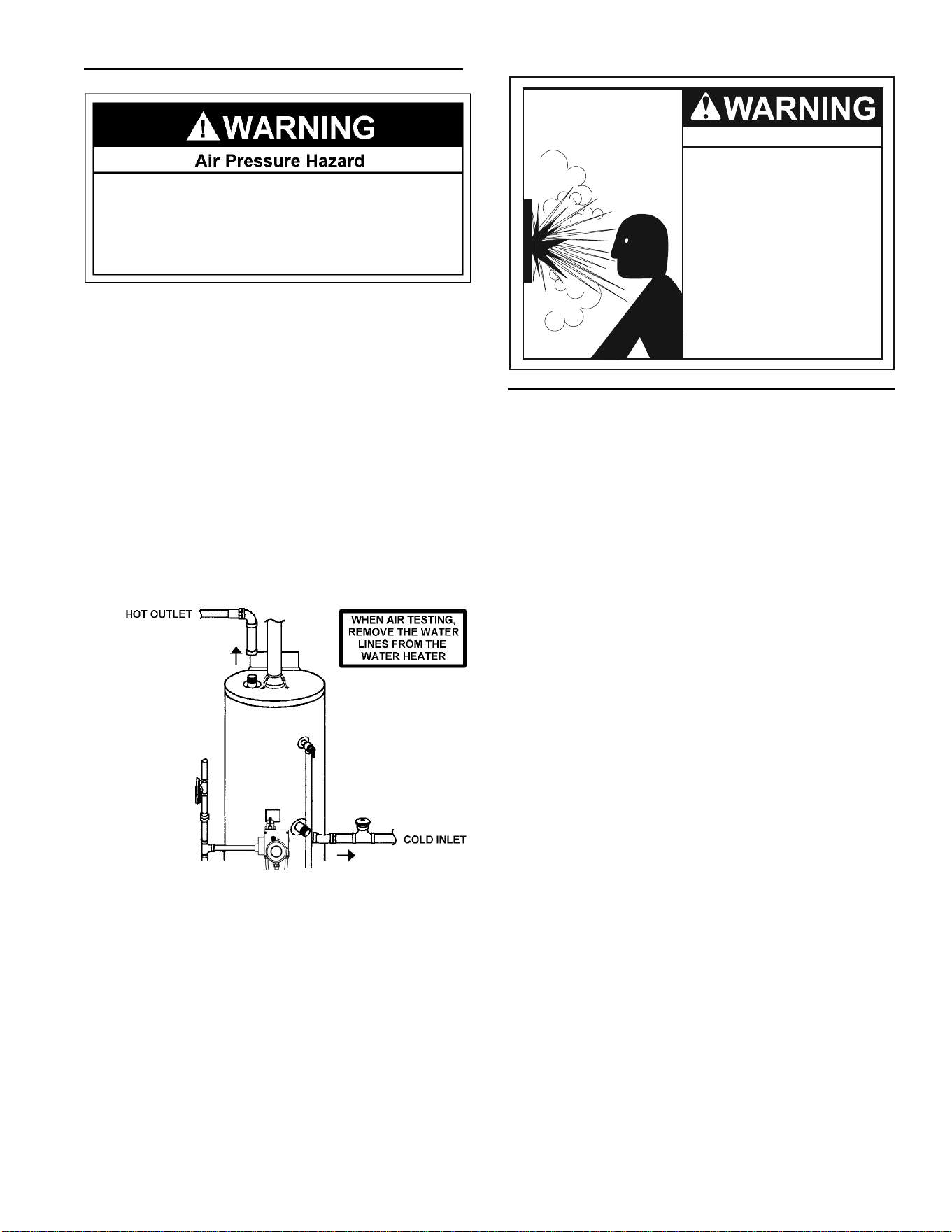
WATER PIPING PRESSURE TEST
,IZDWHUSLSLQJV\VWHPLVWREHDLUSUHVVXUHWHVWHGWKHZDWHU
KHDWHUPXVWEHGLVFRQQHFWHGIURPWKHZDWHUSLSLQJV\VWHP
)DLOXUH WR GLVFRQQHFW WKH ZDWHU KHDWHU GXULQJ DLU SUHVVXUH
WHVWLQJRIWKHZDWHUV\VWHPFRXOGUHVXOWLQ'($7+
6(5,286%2',/<,1-85<253523(57<'$0$*(
This section is only for the manufacturer installing the water heater
when the installation is to comply with H.U.D. standards.
When testing the waterways, H.U.D. standards state:
“Water Distribution System: All water piping in the water distribution
system shall be subjected to a pressure test. The test shall be made
by subjecting the system to air or water at 100 psi (689.48 kPa) for
15 minutes without loss of pressure. When air pressure is used,
the water heater shall not be connected during the test.”
NOTE: If water piping system is to be air pressure tested, the water
heater must be disconnected from the water piping system. Failure
to disconnect the water heater during air pressure testing of water
piping system could result IN DEATH, SERIOUS BODILY INJURY,
OR PROPERTY DAMAGE.
FIGURE 24.
TEMPERATURE-PRESSURE RELIEF VALVE
Explosion Hazard
Temperature-pressure relief
valve must comply with ANSI
Z21.22-CSA 4.4 and ASME code.
Properly sized temperature-
pressure relief valve must be
installed in opening provided.
Do not plug, block, or cap the
discharge line.
Failure to follow this warning
can result in excessive tank
pressure, serious injury or
death.
This heater is provided with a properly certified combination
temperature - pressure relief valve by the manufacturer.
The valve is certifi ed by a nationally recognized testing laboratory
that maintains periodic inspection of production of listed equipment
of materials as meeting the requirements for Relief Valves and
Automatic Gas Shut-off Devices for Hot Water Supply Systems, ANSI
Z21.22 • CSA 4.4, and the code requirements of ASME.
If replaced, the valve must meet the requirements of local codes, but
not less than a combination temperature and pressure relief valve
certifi ed as indicated in the above paragraph.
The valve must be marked with a maximum set pressure not to
exceed the marked hydrostatic working pressure of the water heater
(150 psi = 1,035 kPa) and a discharge capacity not less than the
water heater input rate as shown on the model rating plate.
For safe operation of the water heater, the relief valve must not be
removed from its designated opening nor plugged.
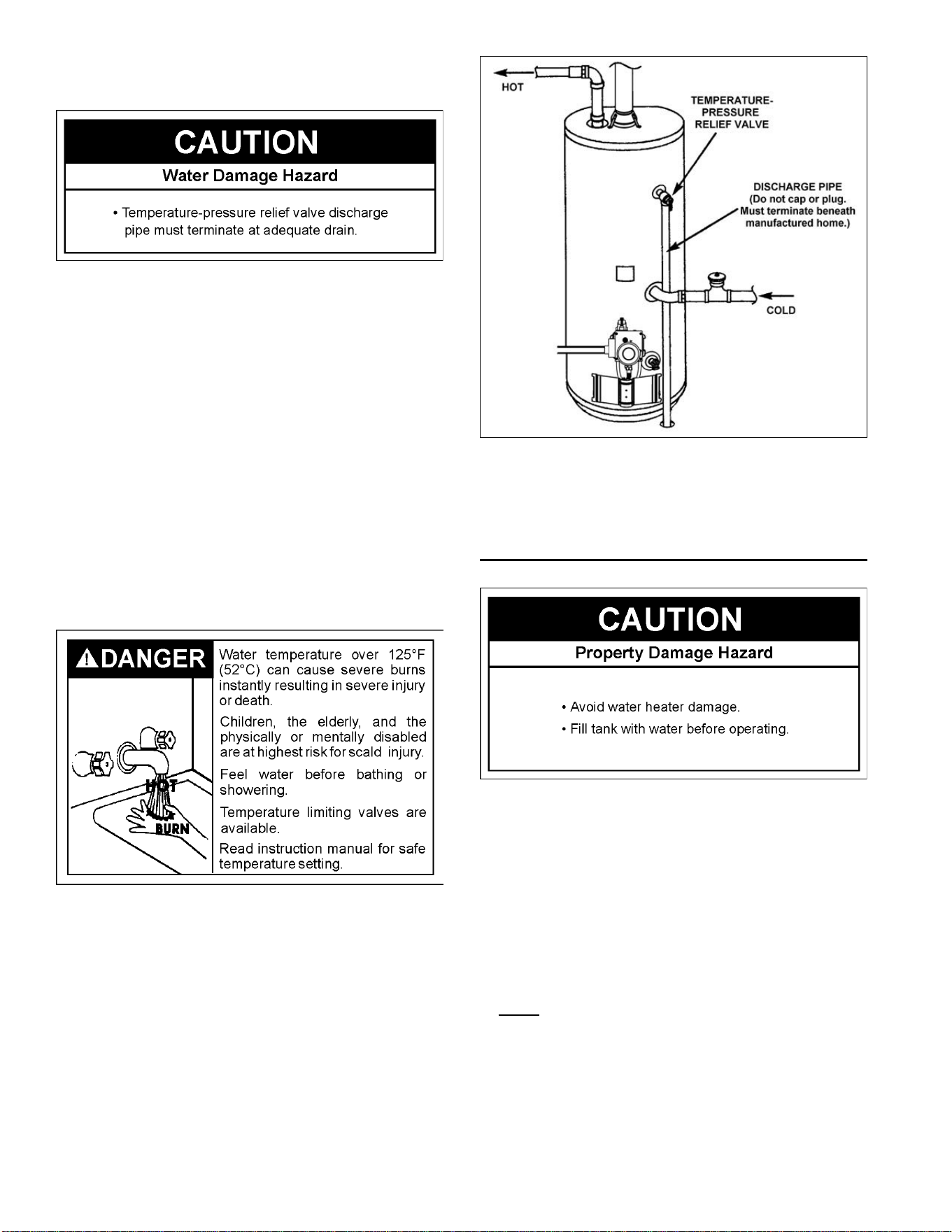
The temperature-pressure relief valve must be installed directly into
the fi tting of the water heater designed for the relief valve. Position
the valve downward and provide tubing so that any discharge will exit
only at any distance below the structural fl oor. Be certain that no
contact is made with any live electrical part. The discharge opening
must not be blocked or reduced in size under any circumstances.
Excessive length, over 30 feet (9.14 m), or use of more than four
elbows can cause restriction and reduce the discharge capacity of
the valve. See Figure 25.
No valve or other obstruction is to be placed between the relief valve
and the tank. To prevent bodily injury, hazard to life, or property
damage, the relief valve must be allowed to discharge water in
quantities should circumstances demand. If the discharge pipe is
not connected to a drain or other suitable means, the water fl ow may
cause property damage.
16
The Discharge Pipe:
• Shall not be smaller in size than the outlet pipe size of the valve, or
have any reducing couplings or other restrictions.
• Shall not be plugged or blocked.
• Shall be of material listed for hot water distribution.
• Shall be installed so as to allow complete drainage of both the
temperature-pressure relief valve, and the discharge pipe.
• Shall pass through the structural fl oor and terminate external to the
building. In cold climates, it is recommended that the discharge
pipe be terminated at an adequate drain inside the building.
• Shall not have any valve between the relief valve and tank.
The temperature-pressure relief valve must be manually operated
at least once a year. Caution should be taken to ensure that (1) no
one is in front of or around the outlet of the temperature-pressure
relief valve discharge line, and (2) the water manually discharged
will not cause any bodily injury or property damage because the
water may be extremely hot.
If after manually operating the valve, it fails to completely reset and
continues to release water, immediately close the cold water inlet
to the water heater, follow the draining instructions, and replace the
temperature-pressure relief valve with a new one.
FIGURE 25.
FILLING THE WATER HEATER
Never use this water heater unless it is completely full of water.
To prevent damage to the tank, the tank must be fi lled with water.
Water must fl ow from the hot water faucet before turning “ON” gas
to the water heater.
To fi ll the water heater with water:
1. Close the water heater drain valve by turning the handle to the
right (clockwise). The drain valve is on the lower front of the water
heater.
2. Open the cold water supply valve to the water heater.
NOTE: The cold water supply valve must be left open when
the water heater is in use.
3. To ensure complete fi lling of the tank, allow air to exit by opening
the nearest hot water faucet. Allow water to run until a constant
fl ow is obtained. This will let air out of the water heater and the
piping.
4. Check all water piping and connections for leaks. Repair as
needed.
17
Explosion Hazard
• Use a new CSA approved gas supply line.
• Install a shut-off valve.
• Do not connect a natural gas water heater to an
L.P. gas supply.
• Do not connect an L.P. gas water heater to a
natural gas supply.
• Failure to follow these instructions can result in
death, explosion, or carbon monoxide poisoning.
WARNING
GAS REQUIREMENTS
IMPORTANT: Read the rating plate to be sure the water heater is made
for the type of gas you will be using in your home. This information
will be found on the rating plate located near the gas control valve/
thermostat. If the information does not agree with the type of gas
available, do not install or light. Call your dealer.
NOTE: An odorant is added by the gas supplier to the gas used by
this water heater. This odorant may fade over an extended period of
time. Do not depend upon this odorant as an indication of leaking gas.
GAS PIPING
The gas piping must be installed according to all local and state
codes or, in the absence of local and state codes, the “National Fuel
Gas Code”, ANSI Z223.1 (NFPA 54)-current edition. Manufactured
home manufacturers must conform with “The Manufactured Home
Construction and Safety Standard, Title 24 CFR, Part 3280”.
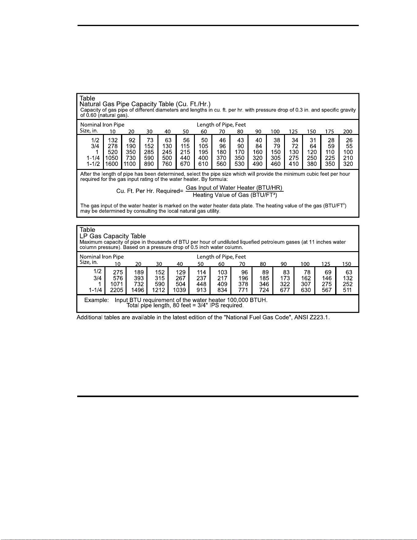
Tables 3 and 4 on page 19 provide a sizing reference for commonly
used gas pipe materials. Consult the “National Fuel Gas Code” for
the recommended gas pipe size of other materials.
NOTE: Use pipe joint compound or Tefl on
®
tape marked as be-
ing resistant to the action of petroleum [Propane (L.P.)] gases.
Refer to Figure 27 as you review the following items:
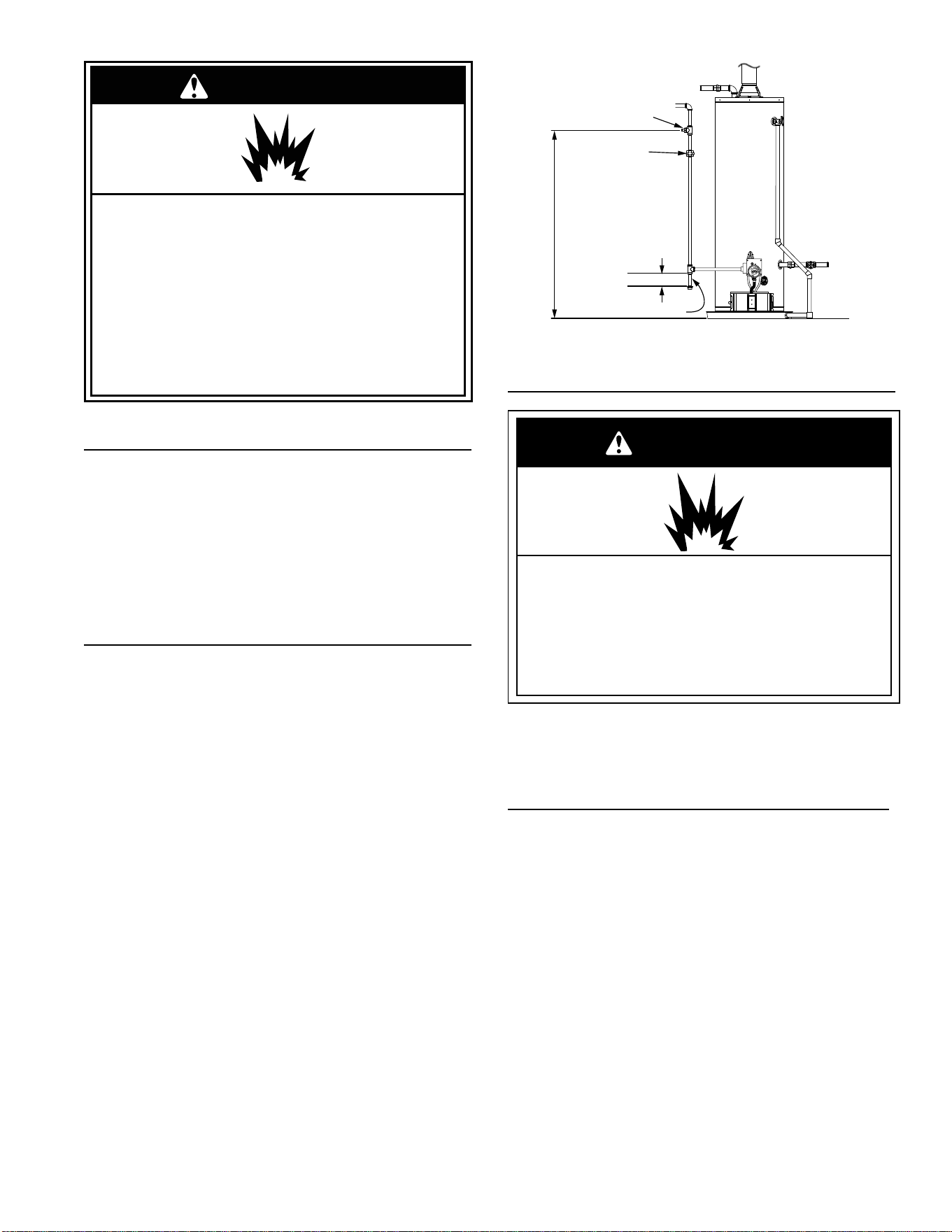
1. Install a readily accessible manual shut-off valve in the gas
supply line as recommended by the local utility. Know the
location of this valve and how to turn off the gas to this unit.
2. Install a sediment trap (if not already incorporated as part of
the water heater) as shown. The sediment trap must be no
less than three inches long for the accumulation of dirt, foreign
material, and water droplets. See also Sediment Traps.
3. Install a ground joint union between the gas control valve/
thermostat and the manual shut-off valve. This is to allow easy
removal of the gas control valve/ thermostat.
4. Turn the gas supply on and check for leaks. Test all connections
by brushing on an approved noncorrosive leak-detection
solution. Bubbles will show a leak. Correct any leak found.
Tefl on
®
is a registered trademark of E. I. du Pont de Nemours and Company.
CHECK WITH
LOCAL UTILITY
FOR MINIMUM HEIGHT
3” (7.62cm) MINIMUM
SEDIMENT TRAP
GROUND
JOINT
UNION
MANUAL GAS
SHUT-OFF VALVE
FIGURE 27.
GAS PRESSURE
WARNING
Explosion Hazard
• Gas leaks can not always be detected by smell.
• Gas suppliers recommend that you use a gas
detector approved by UL or CSA.
• For more information, contact your gas supplier.
• If a gas leak is detected, follow the “What to do if you
smell gas” instructions on the cover of this manual.
IMPORTANT: The gas supply pressure must not exceed the maxi-
mum supply pressure as stated on the water heater’s rating plate.
The minimum supply pressure is for the purpose of input adjustment.
GAS PRESSURE TESTING
IMPORTANT: This water heater and its gas connection must be leak
tested before placing the appliance in operation.
• If the code requires the gas lines to be tested at a pressure
exceeding 14” W.C. (3.5 kPa), the water heater and its manual
shut-off valve must be disconnected from the gas supply piping
system and the line capped.
• If the gas lines are to be tested at a pressure less than 14” W.C.
(3.5 kPa), the water heater must be isolated from the gas supply
piping system by closing its manual shut-off valve.
U.L. recognized fuel gas and carbon monoxide (CO) detectors are
recommended in all applications and should be installed using the
manufacturer’s instructions and local codes, rules and regulations.
NOTE: Air may be present in the gas lines and could prevent the pilot
from lighting on initial start-up. The gas lines should be purged of air
by a qualifi ed technician after installation of the gas piping system.
While purging the gas piping system of air, ensure that the fuel is not
spilled in the area of the water heater installation, or any source of
ignition. If the fuel is spilled while purging the piping system of air
follow the “WHAT TO DO IF YOU SMELL GAS” instructions on the
cover of this manual.
18
LP GAS ONLY
Liquefi ed petroleum gas is over 50% heavier than air and in the
occurrence of a leak in the system, the gas will settle at fl oor level.
Basements, crawl spaces, skirted areas under mobile homes (even
when ventilated), closets and areas below ground level will serve
as pockets for the accumulation of gas. Before lighting an L.P. gas
water heater, smell all around the appliance at fl oor level. If you smell
gas, follow the instructions as given in the warning on the front page.
When your L.P. tank runs out of fuel, turn off the gas at all gas
appliances including pilot lights. After the tank is refi lled, all appliances
must be re-lit according to their manufacturer’s instructions.
WARNING
Explosion Hazard
Have a qualified technician make sure that the L.P.
gas operating pressure does not exceed 13” water
column (3.237 kilopascals).
Failure to do so can result in death, explosion, or fire.
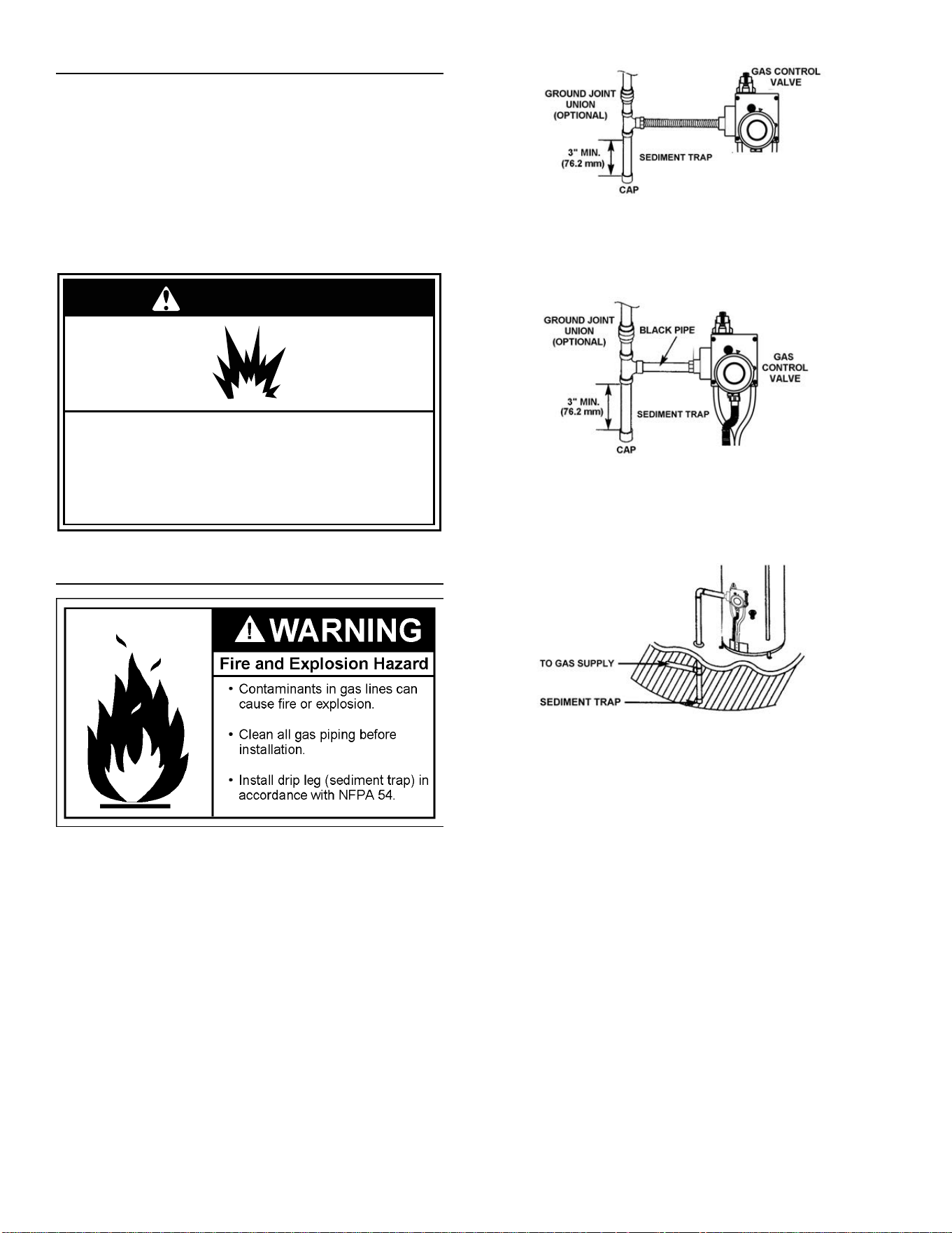
Sediment Traps
A sediment trap shall be installed as close to the inlet of the water
heater as practical at the time of water heater installation. The sediment
trap shall be either a tee fi tting with a capped nipple in the bottom
outlet or other device recognized as an effective sediment trap. If a
tee fi tting is used, it shall be installed in conformance with one of the
methods of installation shown in Figures 28, 29, and 30.
FIGURE 27. GAS PIPING WITH FLEXIBLE CONNECTOR
FIGURE 28. GAS PIPING WITH ALL
BLACK IRON PIPE TO GAS CONTROL VALVE/THERMOSTAT
FIGURE 29. ALTERNATIVE SEDIMENT TRAP LOCATION
Contaminants in the gas lines may cause improper operation of
the gas control valve/thermostat that may result in fi re or explosion.
Before attaching the gas line be sure that all gas pipe is clean on the
inside. To trap any dirt or foreign material in the gas supply line, a
sediment trap (sometimes called a drip leg) must be incorporated in
the piping. The sediment trap must be readily accessible. Install in
accordance with the “Gas Piping” section. Refer to the current edition
of the National Fuel Gas Code, ANSI Z223.1/NFPA 54.
19
4
3

20
INSTALLATION REQUIREMENTS FOR THE
COMMONWEALTH OF MASSACHUSETTS
For all side wall terminated, horizontally vented power vent, direct vent, and power direct vent gas fueled water heaters installed
in every dwelling, building or structure used in whole or in part for residential purposes, including those owned or operated by
the Commonwealth and where the side wall exhaust vent termination is less than seven (7) feet above ¿ nished grade in the
area of the venting, including but not limited to decks and porches, the following requirements shall be satis¿ ed:
INSTALLATION OF CARBON MONOXIDE DETECTORS At the time of installation of the side wall horizontal vented gas
fueled equipment, the installing plumber or gas¿ tter shall observe that a hard wired carbon monoxide detector with an alarm
and battery back-up is installed on the À oor level where the gas equipment is to be installed. In addition, the installing plumber
or gas¿ tter shall observe that a battery operated or hard wired carbon monoxide detector with an alarm is installed on each
additional level of the dwelling, building or structure served by the sidewall horizontal vented gas fueled equipment. It shall
be the responsibility of the property owner to secure the services of quali¿ ed licensed professionals for the installation of hard
wired carbon monoxide detectors.
In the event that the side wall horizontally vented gas fueled equipment is installed in a crawl space or an attic, the hard wired
carbon monoxide detector with alarm and battery back-up may be installed on the next adjacent À oor level.
In the event that the requirements of this subdivision can not be met at the time of completion of installation, the owner shall
have a period of thirty (30) days to comply with the above requirements provided that during said thirty (30) day period, a bat-
tery operated carbon monoxide detector with an alarm shall be installed.
APPROVED CARBON MONOXIDE DETECTORS Each carbon monoxide detector as required in accordance with the above
provisions shall comply with NFPA 720 and be ANSI/UL 2034 listed and CSA certi¿ ed.
SIGNAGE A metal or plastic identi¿ cation plate shall be permanently mounted to the exterior of the building at a minimum height
of eight (8) feet above grade directly in line with the exhaust vent terminal for the horizontally vented gas fueled heating appli-
ance or equipment. The sign shall read, in print size no less than one-half (1/2) inch in size, “GAS VENT DIRECTLY BELOW.
KEEP CLEAR OF ALL OBSTRUCTIONS.”
INSPECTION The state or local gas inspector of the side wall horizontally vented gas fueled equipment shall not approve the
installation unless, upon inspection, the inspector observes carbon monoxide detectors and signage installed in accordance
with the provisions of 248 CMR 5.08(2)(a) 1 through 4.
EXEMPTIONS: The following equipment is exempt from 248 CMR 5.08(2)(a)1 through 4:
1. The equipment listed in Chapter 10 entitled “Equipment Not Required To Be Vented” in the most current edition of NFPA 54
as adopted by the Board; and
2. Product Approved side wall horizontally vented gas fueled equipment installed in a room or structure separate from the
dwelling, building, or structure used in whole or in part for residential purposes.
MANUFACTURER REQUIREMENTS - GAS EQUIPMENT VENTING SYSTEM PROVIDED When the manufacturer of Product
Approved side wall horizontally vented gas equipment provides a venting system design or venting system components with
the equipment, the instructions provided by the manufacturer for installation of the equipment and the venting system shall
include:
1. Detailed instructions for the installation of the venting system design or the venting system components; and
2. A complete parts list for the venting system design or venting system.
MANUFACTURER REQUIREMENTS - GAS EQUIPMENT VENTING SYSTEM NOT PROVIDED When the manufacturer of
a Product Approved side wall horizontally vented gas fueled equipment does not provide the parts for venting the À ue gases,
but identi¿ es “special venting systems,” the following requirements shall be satis¿ ed by the manufacturer:
1. The referenced “special venting system” instructions shall be included with the appliance or equipment installation
instructions; and
2. The “special venting systems” shall be Product Approved by the Board, and the instructions for that system shall include a
parts list and detailed installation instructions.
A copy of all installation instructions for all Product Approved side wall horizontally vented gas fueled equipment, all venting
instructions, all parts lists for venting instructions, and/or all venting design instructions shall remain with the appliance or
equipment at the completion of the installation.
21
GAS CONVERSION
WATER HEATER LOCATION
Water heater location is important and can affect system
performance. Please check the following:
□ Installation area free of corrosive elements and flammable
materials.
□ Centrally located with the water piping system (For new
installations). Located as close to the gas piping and vent pipe
system as possible.
□ Located indoors and in a vertical position. Protected from
freezing temperatures.
□ Proper clearances from combustible surfaces
maintained and not installed directly on a carpeted floor.
□ Provisions made to protect the area from water damage. Metal
drain pan installed and piped to an adequate drain or external
to the building.
□ Sufficient room to service the water heater. See the “Facts to
Consider About the Location” section of this manual.
□ Water heater not located near an air moving device.
□ Water heater securely anchored.
GAS SUPPLY AND PIPING
□ Gas supply is the same type as listed on the water heater rating
plate.
□ Gas line equipped with shut-off valve, union, and sediment trap.
□ Approved pipe joint compound used.
□ Adequate pipe size and of approved material.
□ Chloride-free soap and water solution or other approved
means used to check all connections and fittings for possible
gas leaks.
COMBUSTION AIR SUPPLY / VENT PIPE SYSTEM
□ Sufficient fresh air supply provided from outdoors as described
in this manual, free of corrosive elements and flammable
vapors.
□ All venting installed according to applicable codes and
manufacturers’ instructions.
□ Vent pipe and fittings of approved material; approved roof jack.
□ 12” (30.48 cm) Min. above grade/snow level.
WATER SYSTEM PIPING
□ Temperature and pressure relief valve properly installed with
a discharge line. (Discharge line must be run to an adequate
drain or external to the building and protected from freezing.)
□ All piping properly installed and free of leaks.
□ Heater completely filled with water.
□ Closed system pressure build-up precautions installed (i.e.,
thermal expansion tank).
□ Mixing valve installed per manufacturer’s instructions.
INSTALLATION CHECKLIST
This gas water heater was manufactured to voluntary safety standards to reduce the likelihood of a fl ammable vapor ignition incident. The
new technology used in meeting these standards makes this product more sensitive to installation errors. Please review the following checklist
and make any required installation upgrades or changes.
Questions? Contact Residential Technical Assistance.
This water heater is originally shipped for use with Natural
Gas but can be converted to LP (Propane) Gas by following
the instructions outlined below. To convert this water heater,
you must change both the conversion fitting in the gas control
valve/thermostat AND manifold/burner assembly (supplied).
Both the gas valve and the manifold burner assembly must
be correct for the type of gas used. If you are unsure about
converting this water heater to use a different type of gas,
contact a qualified person such as a plumber or your gas
supplier.
1. Contact your gas company to determine the type of gas
supplied to your home.
2. Check the setting of the conversion fitting in the gas
control valve.
3. Check the label on the manifold burner assembly door.
4. Make sure both the conversion fitting and the manifold
burner assembly (see door label) are for the type of gas
supplied to your home.
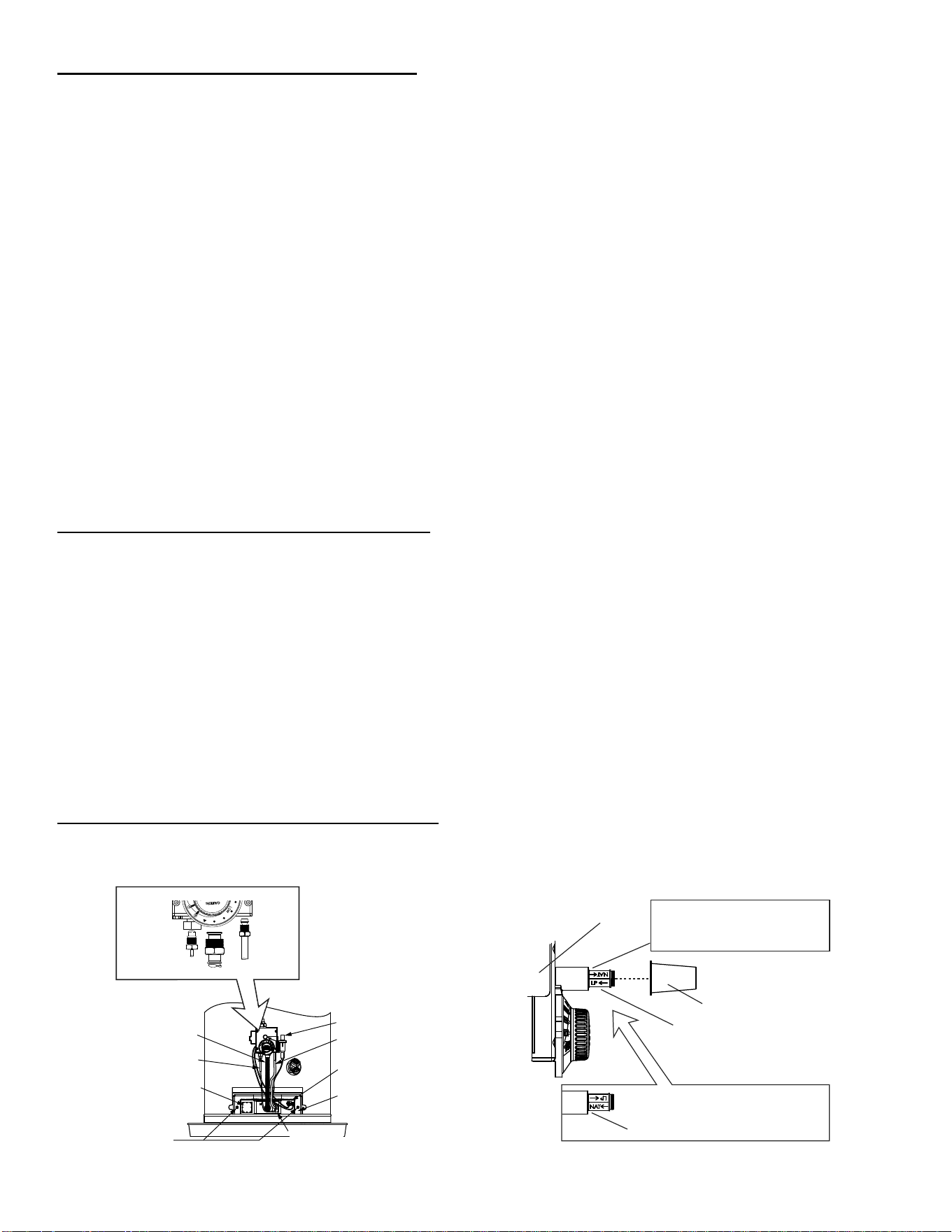
5. If you are converting this water heater from Natural to LP
or from LP to Natural, follow these steps and instructions:
• Remove manifold/burner assembly (instructions below).
• Convert the gas control valve/thermostat to same type of
gas (instructions on page 22).
• Install the replacement manifold/burner assembly (for
conversion; instructions on page 22).
• Place sticker next to data plate showing the type of gas
this water heater has been converted to use.
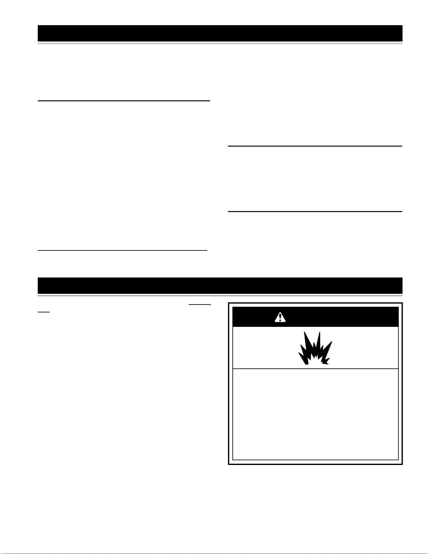
WARNING
Explosion Hazard
Tighten both manifold door screws securely.
Remove any fiberglass between gasket and combustion
chamber.
Replace viewport if glass is missing or damaged.
Replace manifold component block if missing or removed.
Replace door gasket if damaged.
'RQRWFRQQHFWDQ/3JDVZDWHUKHDWHUWRDQDWXUDOJDV
supply.
'RQRWFRQQHFWDQDWXUDOJDVZDWHUKHDWHUWRDQ/3JDV
supply.
Failure to follow these instructions can result in death,
explosion, or fire.
22
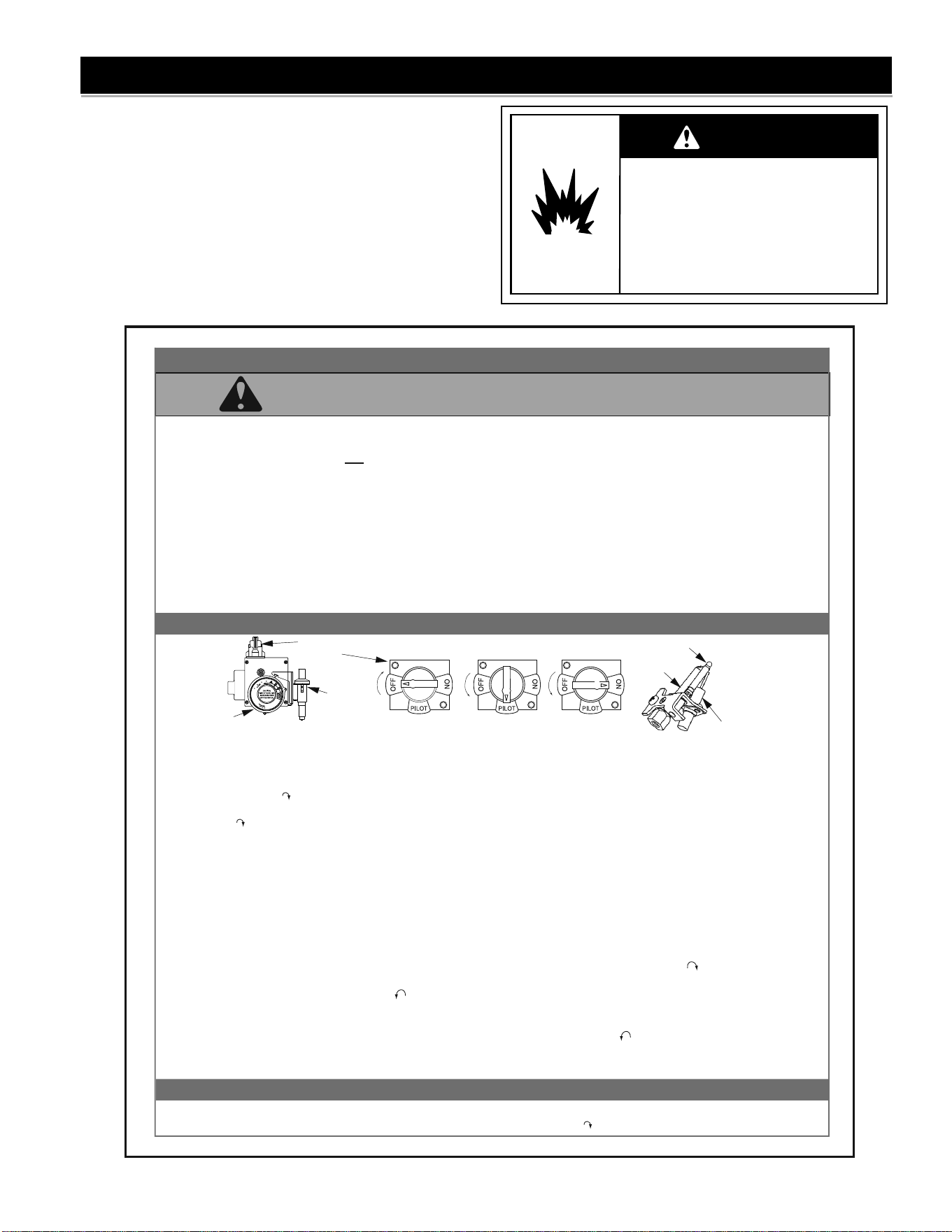
A. Remove the Manifold/Burner Assembly
1. Turn off the gas supply to the water heater at the manual gas
shut-off valve (Figure 26). This valve is typically located be-
side the water heater. Note the position of the shut-off valve
in the open/on position, then proceed to turn it off.
2. On the lower front of the water heater, locate the gas control
valve/thermostat (Figure 30). Before per forming any mainte-
nance, it is important to turn the temperature dial on the gas
control valve/thermostat to its lowest setting.
3. On top of the gas control valve/thermostat, turn the gas
control knob to the “OFF” position.
4. Remove the outer door.
5. Remove the two screws securing the manifold/burner as-
sembly to the combustion chamber (Figure 30).
6. Disconnect the following items from the gas control valve/
thermostat: thermocouple, pilot tube, and manifold tube
(each has right-hand threads). See Figure 30.
7. Disconnect the igniter wire from the piezo igniter button. See
Figure 30.
8. Grasp the manifold tube and push down slightly to free the
manifold, pilot tube, and thermocouple.
9. Carefully remove the manifold/burner assembly from the
burner compartment.
NOTICE: Be sure not to damage internal parts
B. Convert the Gas Control Valve/Thermostat
1. Remove the cap (shown in Figure 31), then remove the con-
version fitting by turning it counter-clockwise with an adjust-
able wrench.
2. Thread the opposite end of the conversion fitting into the
opening by turning it clockwise, then tighten it hand tight.
A. If you are converting the unit to use LP gas (propane),
verify that the “LP” arrow on the fitting is pointing toward
the gas control valve/thermostat. The red band on the
fitting should touch the metal boss. See Figure 31.
B. If you are converting the unit to use natural gas, verify
that the “NAT” arrow on the fitting is pointing toward the
gas control valve/thermostat. The blue band on the
fitting should touch the metal boss. See Figure 31.
3. Replace the cap.
C. Install the Conversion Manifold/Burner Assembly
1. Check the door gasket for damage or imbedded debris prior to
installation. See Figure 42.
2. Inspect the view port for damage and replace as required.
3. Insert the replacement manifold/burner assembly into the
burner compartment, making sure that the tip of the manifold
tube engages in the slot of the bracket inside the combustion
chamber. See Figure 43.
4. Inspect the door gasket and make sure there is no fiberglass
insulation between the gasket and the combustion chamber.
5. Replace the two screws which secure the manifold/burner
assembly door to the combustion chamber and tighten se-
curely. Once the manifold/burner assembly door is tightened,
visually inspect the door gasket between the manifold/burner
assembly door and the combustion chamber for spaces or
gaps that would prevent a seal.
WARNING! Do not operate the water heater if the door gas-
ket does not create a seal between the manifold door and the
combustion chamber. Failure to observe this warning could
lead to personal injury or death.
6. Reconnect the manifold tube, pilot tube, and thermocouple
to the gas control valve/thermostat. See Figure 30. Do not
cross-thread or apply any thread sealant to these fittings.
The thermocouple nut should be started and turned all the
way in by hand. Tighten an additional quarter turn with a
7/16” open-end wrench.
NOTICE: If you were supplied with a new ferrule nut in a
parts kit, follow these steps to connect the pilot tube:
A.) Install the ferrule nut into the gas valve at the pilot tube
location, hand tight only. B.) Insert the pilot tube into the fer-
rule nut until the tube bottoms out, then tighten the nut with
a 7/16” wrench until the crimp connection seals to the pilot
tube. C.) Continue to tighten until the nut is tight in the gas
valve.
7. Reconnect the igniter wire.
8. Turn gas supply on and refer to the Lighting Instructions.
9. With the burner lit, check the gas control valve/ thermostat
supply line, manifold component block, manifold tube, and
pilot tube connections for leaks. Check for leaks by brush-
ing on an approved non-corrosive leak detection solution.
Bubbles forming indicate a leak. Correct any leak found.
WARNING! All leaks must be fixed immediately. Failure to
do so could lead to personal injury or death.
10. Verify proper operation; replace outer door.
11. Place the conversion label next to the rating plate. (The
conversion label shows the type of gas that your water heater
has been converted to use.)
THERMOCOUPLE
MANIFOLD TUBE
PILOT
TUBE
WITH
FERRULE
NUT
GAS CONTROL VALVE / THERMOSTAT
MANIFOLD
SCREWS (2)
MANIFOLD
TUBE
THERMOCOUPLE
VIEW PORT
TWO PIECE
WIRE CONNECTOR
MANIFOLD
DOOR
THERMAL
SWITCH
PILOT
TUBE
PIEZO
IGNITER
BUTTON
GAS CONTROL VALVE/
THERMOSTAT
CONVERSION FITTING
CAP
LP GAS:
“LP” ARROW POINTS TOWARD THE
GAS CONTROL VALVE/ THERMOSTAT.
RED BAND TOUCHES METAL BOSS.
NATURAL GAS:
“NAT” ARROW POINTS TOWARD THE GAS
CONTROL VALVE/ THERMOSTAT.
BLUE BAND TOUCHES METAL BOSS.
FIGURE 30.
FIGURE 31.
23
LIGHTING INSTRUCTIONS
WARNING
Explosion Hazard
Replace view port if glass is missing
or damaged.
Failure to do so can result in death,
explosion or fire.
Read and understand these directions thoroughly before attempt-
ing to light or re-light the pilot. Make sure that the view port (sight
glass) is not missing or damaged. (See Figure 40.) Make sure the
tank is completely fi lled with water before lighting the pilot. Check
the rating plate near the gas control valve/thermostat for the correct
gas. Do not use this water heater with any gas other than the one
listed on the rating plate unless the water heater has been properly
converted. Refer to the “Gas Conversion” section of this manual. If
you have any questions or doubts, consult your gas supplier or gas
utility company.
FOR YOUR SAFETY READ BEFORE LIGHTING
WARNING: If you do not follow these instructions exactly, a fire or explosion may result
causing property damage, personal injury or loss of life.
LIGHTING INSTRUCTIONS
TO TURN OFF GAS TO APPLIANCE
BEFORE LIGHTING: ENTIRE SYSTEM MUST BE FILLED WITH WATER AND AIR PURGED FROM ALL LINES
A. This appliance has a pilot which is lit by a piezo-electric
spark gas ignition system. Do not open the inner door
of the appliance and try to light the pilot by hand.
B. BEFORE LIGHTING smell all around the appliance
area for gas. Be sure to smell next to the floor because
some gas is heavier than air and will settle on the floor.
WHAT TO DO IF YOU SMELL GAS
• Do not try to light any appliance.
• Do not touch any electric switch; do not use any
phone in your building.
• Immediately call your gas supplier from a neighbor's
phone. Follow the gas supplier's instructions.
• If you cannot reach your gas supplier, call the fire
department.
C.Use only your hand to push in or turn the gas control
knob. Never use tools. If the knob will not push in or turn
by hand, do not try to repair it, call a qualified service
technician. Force or attempted repair may result in a fire
or explosion.
D. Do not use this appliance if any part has been
underwater. Immediately contact a qualified installer or
service agency to replace a flooded water heater. Do not
attempt to repair the unit! It must be replaced!
1. STOP! Read the safety information above on this label.
2. Set thermostat to lowest setting by turning thermostat
dial fully clockwise .
3. Push the gas control knob down slightly and turn
clockwise to "OFF". SEE FIGURE 'A'. NOTE: Knob
cannot be turned from "PILOT" to "OFF" unless knob is
pushed down slightly. Do not force.
4. Remove the outer burner door located below the gas
control.
5. Wait five (5) minutes to clear out any gas. If you then
smell gas, STOP! Follow "B" in the safety information
above on this label. If you don't smell gas, go to next
step.
6. This unit is equipped with a push button pilot ignitor,
which is used to light the pilot. Locate the ignitor on the
gas control.
7. Turn gas control knob counterclockwise to "PILOT".
SEE FIGURE 'B'.
8. The pilot is located on the left side of the burner. It can
be located by looking through the glass view port while
pressing the piezo ignitor button several times. Look
for a spark at the pilot location, Figure "D".
9. Once the pilot has been found, push the gas knob all
the way down. Immediately press and release the pilot
ignitor button continuously up to (10) times. If the pilot
will not light, repeat steps (3) through (9).
10. Continue to hold the gas control knob down for about
one (1) minute after the pilot is lit. Release the gas
control knob and it will pop back up. Pilot should
remain lit. If it goes out, repeat step (9). It may take
several minutes for air to clear the lines before the pilot
will light.
• If knob does not pop up when released, stop and
immediately call your service technician or gas
supplier.
• If the pilot will not stay lit after several tries, turn the
gas control knob clockwise to 'OFF' and call your
service technician or gas supplier. SEE FIGURE 'A'.
11. Once the pilot flame is established replace the outer
burner door.
12. At arm's length away, turn gas control knob
counterclockwise to 'ON'. SEE FIGURE 'C'.
13. Set thermostat to desired setting.
FIGURE "D"
THERMOCOUPLE
PILOT
ELECTRODE
TOP KNOB
"ON" POSITION
FIGURE 'C'
"PILOT" POSITION
FIGURE 'B'
"OFF" POSITION
FIGURE 'A'
GAS CONTROL
KNOB
THERMOSTAT
DIAL
GAS CONTROL
PIEZO
IGNITOR
1. Turn the thermostat dial to lowest setting (PILOT
LIGHTING).
2. Push gas control knob down slightly and turn
clock-wise to 'OFF'. Do not force. SEE FIGURE 'A'.
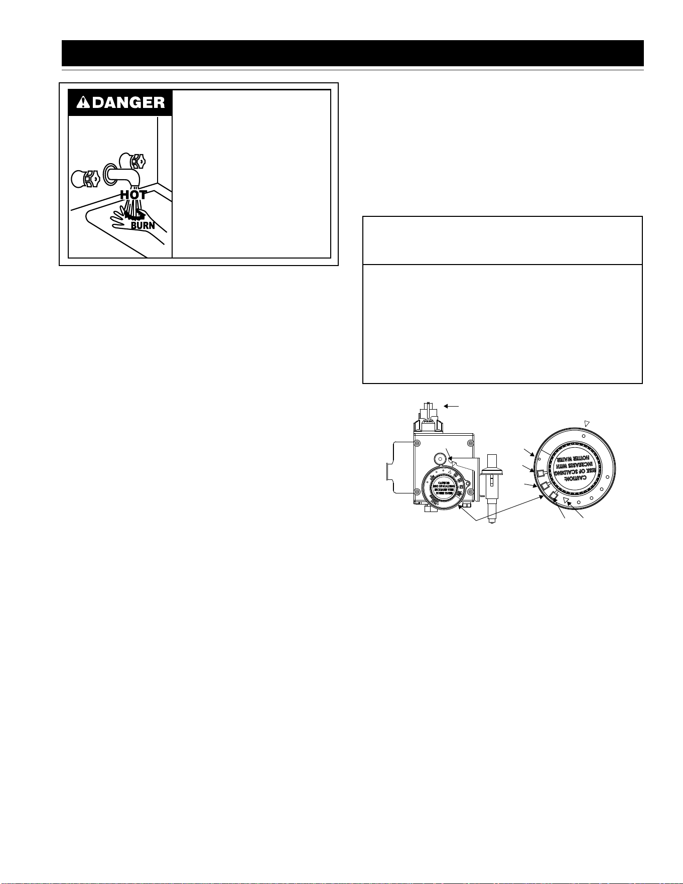
24
TEMPERATURE REGULATION
Water temperature over 125°F (52°C)
can cause servere burns instantly
resulting in severe injury or death.
Children, the elderly, and the
physically or mentally disabled are at
highest risk for scald injury.
Feel water before bathing or
showering.
Temperature limiting valves are
available.
Read instruction manual for safe
temperature setting.
Due to the nature of the typical gas water heater, the water
temperature in certain situations may vary up to 30°F
(16.7 °C) higher or lower at the point of use such as, bathtubs,
showers, sink, etc.
HOTTER WATER CAN SCALD: Water heaters are intended to
produce hot water. Water heated to a temperature which will
satisfy clothes washing, dish washing, and other sanitizing needs
can scald and permanently injure you upon contact. Some people
are more likely to be permanently injured by hot water than others.
These include the elderly, children, the infirm, or physically/mentally
handicapped. If anyone using hot water in your home fits into one of
these groups or if there is a local code or state law requiring a certain
temperature water at the hot water tap, then you must take special
precautions. In addition to using the lowest possible temperature
setting that satisfies your hot water needs, a means such as a mixing
valve should be used at the hot water taps used by these people
or at the water heater. Mixing valves are available at plumbing
supply or hardware stores. See Figure 2. Follow manufacturer’s
instructions for installation of the valves. Before changing the factory
setting on the thermostat, see Figure 32. Using the lowest hot water
temperature that meets your needs will also provide the most energy
efficient operation of the water heater.
Never allow small children to use a hot water tap, or to draw their own
bath water. Never leave a child or handicapped person unattended
in a bathtub or shower.
NOTE: A water temperature range of 120°F-140°F (49°C-60°C) is
recommended by most dishwasher manufacturers.
The thermostat is adjusted to the pilot position when it is shipped
from the factory. Water temperature can be regulated by moving
the temperature dial to the preferred setting. The preferred starting
point is 120°F at the “HOT” setting. Align the knob with the desired
water temperature as shown in Figure 34. There is a hot water scald
potential if the thermostat is set too high.
NOTE:
• If the knob is set to a higher temperature setting than 120°F
(48.9°C), a mixing valve should be installed to limit the temperature
of the water to 120°F (48.9°C) at the fixtures.
• Temperatures shown on the gas control valve/thermostat are
approximates. The actual temperature of the heated water may
vary.
IMPORTANT: Adjusting the thermostat past the 120°F (48.9°C)
mark on the temperature dial will increase the risk of scald injury.
Hot water can produce first degree burns within:
Water
Temperature
°F (°C)
Time for 1st
Degree Burn
(Less Severe Burns)
Time for
Permanent Burns
2nd & 3rd Degree
(Most Severe Burns)
110 (43)
116 (47)
116 (47)
122 (50)
131 (55)
140 (60)
149 (65)
154 (68)
(normal shower temp.)
(pain threshold)
35 minutes
1 minute
5 seconds
2 seconds
1 second
Instantaneous
45 minutes
5 minutes
25 seconds
5 seconds
2 seconds
1 second
(U.S. Government Memorandum, C.P.S.C., Peter L. Armstrong, Sept. 15,1978)
INDEX BAR
155°F
GAS CONTROL KNOB
(OFF-PILOT-ON)
150°F
140°F
130°F
120°F
TEMPERATURE DIAL
TEMPERATURES SHOWN ARE APPROXIMATES AND MAY VARY
PILOT
LIGHTING
LOW
A
B
C
VERY
HOT
FIGURE 32.
Should overheating occur or the gas supply fail to shut off, turn off the
manual gas control valve to the appliance.
NOTE: During low demand periods when hot water is not being
used, a lower thermostat setting will reduce energy losses and may
satisfy your normal hot water needs. If hot water use is expected to
be more than normal, a higher thermostat setting may be required to
meet the increased demand. When leaving your home for extended
periods (vacations, etc.) turn the temperature dial to its lowest setting.
This will maintain the water at low temperatures with minimum energy
losses and prevent the tank from freezing during cold weather.
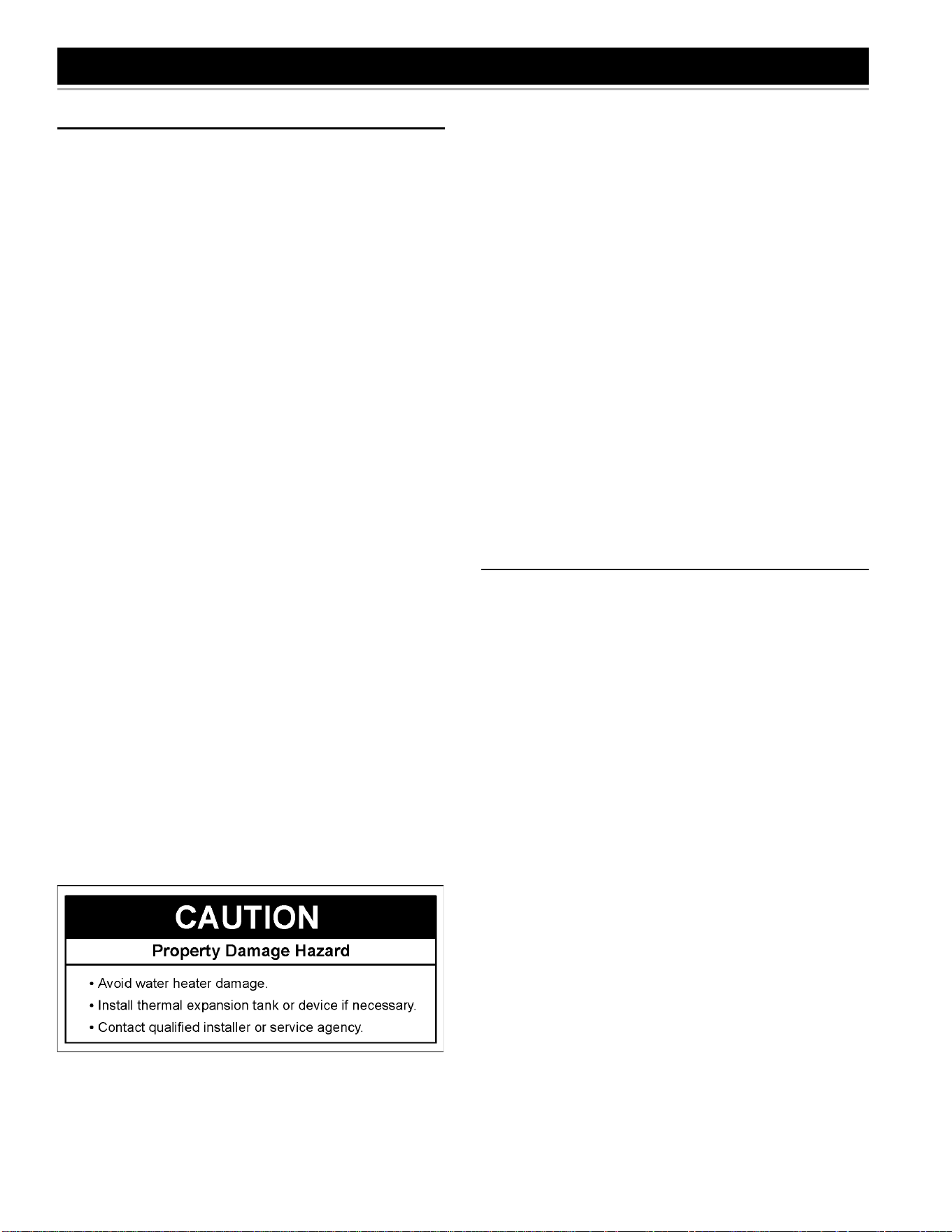
25
FOR YOUR INFORMATION
START UP CONDITIONS
CONDENSATE
Whenever the water heater is fi lled with cold water, some condensate
will form while the burner is on. A water heater may appear to be
leaking when in fact the water is condensation. This usually happens
when:
a. A new water heater is fi lled with cold water for the fi rst time.
b. Burning gas produces water vapor in water heaters, particularly
high effi ciency models where fl ue temperatures are lower.
c. Large amounts of hot water are used in a short time and the refi ll
water in the tank is very cold.
Moisture from the products of combustion condense on the cooler
tank surfaces and form drops of water which may fall onto the burner
or other hot surfaces to produce a “sizzling” or “frying” noise.
Excessive condensation can cause pilot outage due to water running
down the fl ue tube onto the main burner and putting out the pilot.
Because of the suddenness and amount of water, condensation water
may be diagnosed as a “tank leak”. After the water in the tank warms
up (about 1-2 hours), the condition should disappear.
Do not assume the water heater is leaking until there has been enough
time for the water in the tank to warm up.
An undersized water heater will cause more condensation. The water
heater must be sized properly to meet the family’s demands for hot
water including dishwashers, washing machines and shower heads.
Excessive condensation may be noticed during the winter and early
spring months when incoming water temperatures are at their lowest.
Good venting is essential for a gas fi red water heater to operate
properly as well as to carry away products of combustion and water
vapor.
SMOKE / ODOR
It is not uncommon to experience a small amount of smoke and odor
during the initial start-up. This is due to burning off of oil from metal
parts, and will disappear in a short while.
THERMAL EXPANSION
As water is heated, it expands (thermal expansion). In a closed
system, the volume of water will grow. As the volume of water grows,
there will be a corresponding increase in water pressure due to
thermal expansion. Thermal expansion can cause premature tank
failure (leakage). This type of failure is not covered under the limited
warranty. Thermal expansion can also cause intermittent temperature-
pressure relief valve operation: water discharged from the valve due to
excessive pressure build up. The temperature-pressure relief valve is
not intended for the constant relief of thermal expansion. This condition
is not covered under the limited warranty.
A properly-sized thermal expansion tank should be installed on all
closed systems to control the harmful effects of thermal expansion.
Contact a plumbing service agency or your retail supplier regarding
the installation of a thermal expansion tank.
STRANGE SOUNDS
Possible noises due to expansion and contraction of some metal parts
during periods of heat-up and cool-down do not necessarily represent
harmful or dangerous conditions.
Condensation causes sizzling and popping within the burner area
during heating and cooling periods and should be considered normal.
See “Condensate” in this section.
OPERATIONAL CONDITIONS
SMELLY WATER
In each water heater there is installed at least one anode rod (see
parts section) for corrosion protection of the tank. Certain water
conditions will cause a reaction between this rod and the water. The
most common complaint associated with the anode rod is one of a
“rotten egg smell” in the hot water. This odor is derived from hydrogen
sulfi de gas dissolved in the water. The smell is the result of four factors
which must all be present for the odor to develop:
a. A concentration of sulfate in the supply water.
b. Little or no dissolved oxygen in the water.
c. A sulfate reducing bacteria which has accumulated within the water
heater (this harmless bacteria is nontoxic to humans).
d. An excess of active hydrogen in the tank. This is caused by the
corrosion protective action of the anode.
Smelly water may be eliminated or reduced in some water heater
models by replacing the anode(s) with one of less active material, and
then chlorinating the water heater tank and all hot water lines. Contact
the local water heater supplier or service agency for further information
concerning an Anode Replacement Kit and this chlorination treatment.
If the smelly water persists after the anode replacement and
chlorination treatment, we can only suggest that chlorination or
aeration of the water supply be considered to eliminate the water
problem.
Do not remove the anode leaving the tank unprotected. By doing
so, all warranty on the water heater tank is voided.
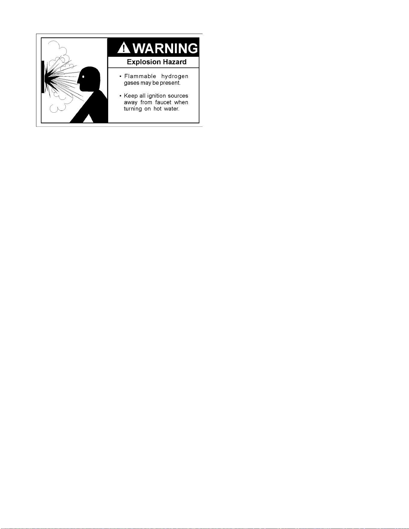
26
“AIR” IN HOT WATER FAUCETS
HYDROGEN GAS: Hydrogen gas can be produced in a hot water
system that has not been used for a long period of time (generally
two weeks or more). Hydrogen gas is extremely fl ammable and
explosive. To prevent the possibility of injury under these conditions,
we recommend the hot water faucet, located farthest away, be
opened for several minutes before any electrical appliances which are
connected to the hot water system are used (such as a dishwasher
or washing machine). If hydrogen gas is present, there will probably
be an unusual sound similar to air escaping through the pipe as the
hot water faucet is opened. There must be no smoking or open fl ame
near the faucet at the time it is open.
SAFETY SHUT OFF SYSTEM
This water heater is designed to automatically shut off in the event
of the following:
1. When the pilot flame is extinguished for any reason.
A thermocouple is used to determine if a pilot fl ame is present
and will shut off the gas supply to the main burner and pilot if
the fl ame is absent.
2. When the water temperature in the tank exceeds 189°F (87°C).
The gas control valve\thermostat includes a temperature
limiting ECO (Energy Cut Off) system that activates when
excessive water temperatures are present. If this occurs, the
system cannot be reset. The gas control valve/thermostat
must be replaced.
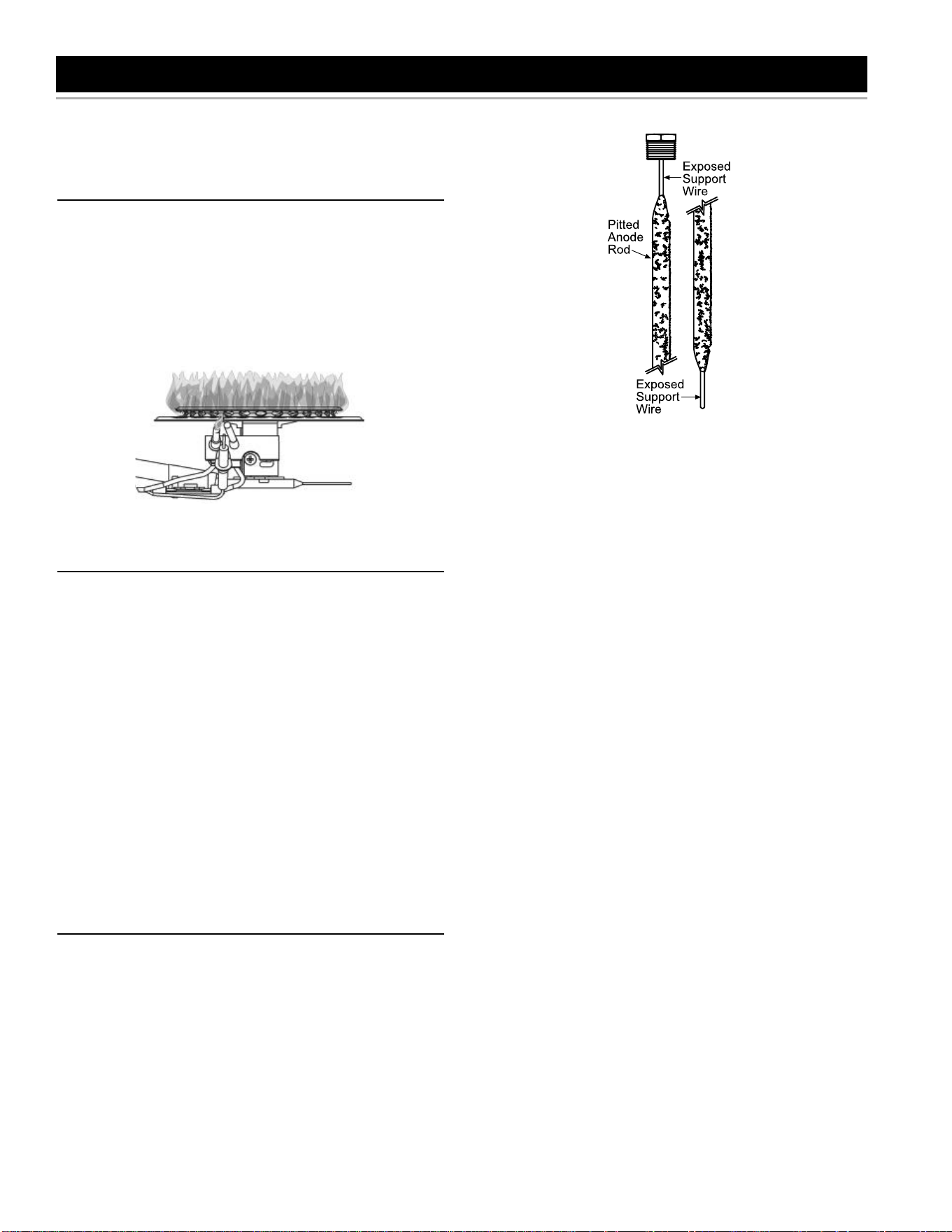
27
MAINTENANCE OF YOUR WATER HEATER
IMPORTANT: If you do not have the skills and training to perform a
maintenance procedure, do not attempt it. Get help from a qualifi ed
technician.
BURNER FLAME INSPECTION
Inspect the burner fl ames through the viewport and compare them to
the drawing in Figure 36. A properly operating burner should produce
a soft blue fl ame. Blue tips with yellow inner cones are satisfactory.
The tips of the fl ame may have a slight yellow tint. The fl ame should
not be all yellow or have a sharp blue-orange color. Contaminated air
may cause an orange colored fl ame. Contact a qualifi ed technician
if the fl ame is not satisfactory.
FIGURE 33.
R O U T I N E P R E V E N T I V E M A I N T E N A N C E
At least annually, a visual inspection should be made of the venting
and air supply system, piping systems, main burner, and pilot burner.
Check the water heater for the following:
• Obstructions, damage, or deterioration in the venting system.
Make sure the ventilation and combustion air supplies are not
obstructed.
• Soot and/or carbon on the main burner and pilot burner.
Contact a qualified technician.
• Leaking or damaged water and gas piping.
• Presence of flammable or corrosive materials in the installation
area.
• Presence of combustible materials near the water heater.
• After servicing this water heater, check to make sure that it is
working properly.
IMPORTANT: If you lack the necessary skills required to properly
perform this visual inspection, you should not proceed, but get help
from a qualifi ed technician.
A N O D E R O D I N S P E C T I O N
Each water heater contains at least one anode rod, which will slowly
deplete (due to electrolysis) prolonging the life of the water heater
by protecting the glass-lined tank from corrosion. Adverse water
quality, hotter water temperatures, high hot water usage, and water
softening methods can increase the rate of anode rod depletion. Once
the anode rod is depleted, the tank will start to corrode, eventually
developing a leak.
Anode Rod Depletion
FIGURE 34.
Certain water conditions will cause a reaction between the anode
rod and the water. The most common complaint associated with
the anode rod is a “rotten egg smell” produced from the presence
of hydrogen sulfi de gas dissolved in the water. IMPORTANT: Do not
remove this rod permanently as it will void any warranties. A special
anode rod may be available if water odor or discoloration occurs.
NOTE: This rod may reduce but not eliminate water odor problems.
The water supply system may require special fi ltration equipment
from a water conditioning company to successfully eliminate all water
odor problems.
Artifi cially softened water is exceedingly corrosive because the process
substitutes sodium ions for magnesium and calcium ions. The use
of a water softener may decrease the life of the water heater tank.
The anode rod should be inspected after a maximum of three years
and annually thereafter until the condition of the anode rod dictates
its replacement. NOTE: Artifi cially softened water requires the anode
rod to be inspected annually. The following are typical (but not all)
signs of a depleted anode rod:
• The majority of the rods diameter is less than 3/8” (9.5 mm).
• Signifi cant sections of the support wire (approx. 1/3 or more of the
anode rod’s length) are visible.
If the anode rod show signs of either or both it should be replaced.
NOTE: Whether re-installing or replacing the anode rod, check for
any leaks and immediately correct if found. In replacing the anode:
1. Turn off gas supply to the water heater.
2. Shut off the water supply and open a nearby hot water faucet to
depressurize the water tank.
3. Drain approximately 5 gallons (18.9 liters) of water from tank. (Refer
to “Draining and Flushing” for proper procedures.) Close drain valve.
4. Remove old anode rod.
5. Use Tefl on
®
tape or approved pipe sealant on threads and install
new anode rod.
6. Turn on water supply and open a nearby hot water faucet to purge
air from water system. Check for any leaks and immediately
correct any if found.
7. Restart the water heater as directed in this manual.
See the Repair Parts illustration for anode rod location.
Tefl on
®
is a registered trademark of E. I. du Pont de Nemours and Company.
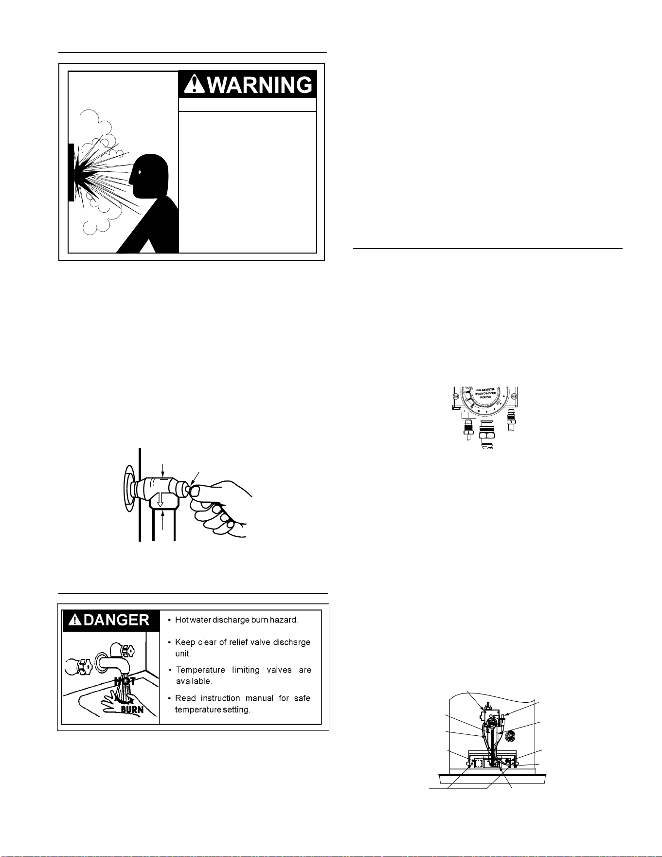
28
TEMPERATURE-PRESSURE RELIEF VALVE OPERATION
Explosion Hazard
7HPSHUDWXUHSUHVVXUHUHOLHI
YDOYHPXVWFRPSO\ZLWK$16,
=&6$DQG$60(
FRGH
3URSHUO\VL]HGWHPSHUDWXUH
SUHVVXUHUHOLHIYDOYHPXVWEH
LQVWDOOHGLQRSHQLQJSURYLGHG
&DQUHVXOWLQRYHUKHDWLQJ
DQGH[FHVVLYHWDQNSUHVVXUH
&DQFDXVHVHULRXVLQMXU\RU
GHDWK
Manually operate the temperature and pressure relief valve at least
once a year to make sure it is working properly. To prevent water
damage, the valve must be properly connected to a discharge line
that passes through the structural fl oor and terminates external to
the building. In cold climates, it is recommended that the discharge
line be terminated at an adequate drain inside the building. See
Figure 1. Standing clear of the outlet (discharged water may be
hot), slowly lift and release the lever handle on the temperature and
pressure relief valve to allow the valve to operate freely and return
to its closed position. See Figure 35. If the valve fails to completely
reset and continues to release water, immediately close the manual
gas shut-off valve and the cold water inlet valve and call a qualifi ed
technician. Do not plug the temperature-pressure relief valve or
discharge line.
TEMPERATURE AND PRESSURE
RELIEF VALVE
DISCHARGE LINE TO DRAIN
MANUAL RELIEF
VALVE
FIGURE 35.
Draining and Flushing
It is recommended that the tank be drained and flushed
every 6 months to remove sediment which may build up during
operation. The water heater should be drained if being shut down
during freezing temperatures. To drain the tank, perform the following
steps:
1. Turn off the gas to the water heater at the manual gas shut-off
valve.
2. Open a nearby hot water faucet until the water is no longer hot.
3. Close the cold water inlet valve.
4. Connect a hose to the drain valve and terminate it to an adequate
drain or external to the building.
5. Open the water heater drain valve and allow all of the water to
drain from the tank. Flush the tank with water as needed to remove
sediment.
6. Close the drain valve, refi ll the tank, and restart the heater as
directed in this manual. If the water heater is going to be shut
down for an extended period, the drain valve should be left open.
IMPORTANT: Condensation may occur when refi lling the tank and
should not be confused with a tank leak.
REMOVING THE MANIFOLD/BURNER ASSEMBLY
1. Turn the gas control/temperature knob to the “OFF” position
(Figure 35).
2. Before performing any maintenance, it is important to turn off
the gas supply to the water heater at the manual gas shut-off
valve. This valve is typically located beside the water heater.
Note the position of the shut-off valve in the open/on position,
then proceed to turn it off (Figure 27).
3. With the unit shut-off, allow sufficient time for the water heater to
cool before performing any maintenance.
THERMOCOUPLE
MANIFOLD TUBE
PILOT
TUBE
WITH
FERRULE
NUT
GAS CONTROL VALVE / THERMOSTAT
FIGURE 36.
4. Remove the outer door.
5. Disconnect the following from the gas control valve/thermostat:
pilot tube (7/16” SAE wrench), igniter wire (from the igniter lead
wire), and manifold tube (3/4” SAE wrench). See Figure 36.
6. Disconnect the white and red wires from the gas control valve/
thermostat (Figure 39). Use needle nose pliers to grip the
connector(s). IMPORTANT: Grip the connector carefully to
prevent damage. Do not grip or pull the wires themselves.
7. Grasp the manifold tube and push down slightly to free the
manifold tube and pilot tube.
8. Remove the screws (1/4” SAE nut driver) securing the manifold/
burner assembly to the combustion chamber. See Figure 37.
9. Carefully remove the manifold/burner assembly from the
combustion chamber. BE SURE NOT TO DAMAGE ANY
INTERNAL PARTS.
MANIFOLD
SCREWS (2)
TWO PIECE
WIRE CONNECTOR
MANIFOLD
DOOR
THERMAL
SWITCH
PILOT
TUBE
PIEZO
IGNITER
BUTTON
GAS CONTROL VALVE/
THERMOSTAT
MANIFOLD
TUBE
THERMOCOUPLE
VIEW PORT
FIGURE 37.
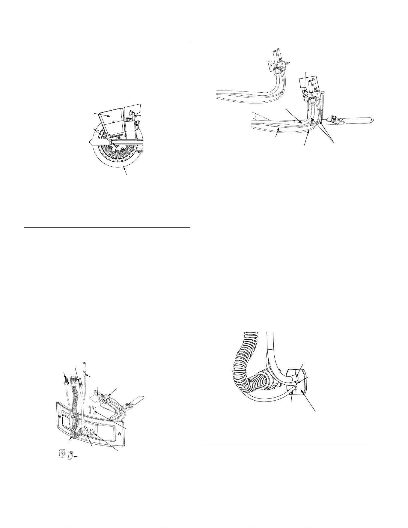
29
REMOVING THE BURNER FROM THE
MANIFOLD/BURNER ASSEMBLY
1. Take off the burner by removing the two (2) screws located
underneath the burner.
2. Check the burner to see if it is dirty or clogged. The burner
may be cleaned with soap and hot water (Figure 41).
BURNER
(BOTTOM VIEW)
SCREWS
PILOT ASSEMBLY
(BOTTOM VIEW)
NOTE: SCOOP NOT PRESENT
ON SOME MODELS
FIGURE 38.
REPLACING THE PILOT/ THERMOCOUPLE
ASSEMBLY
1. Remove the manifold door assembly as described in “Removing
the Manifold/Burner Assembly” section.
2. Remove the burner to access the pilot/thermocouple assembly.
Remove and keep the screws securing the burner to the
manifold (Figure 41). IMPORTANT: DO NOT remove the orifice.
3. Remove the screw securing the pilot/thermocouple assembly to
the pilot bracket and keep for reuse later (Figure 42).
4. Lift the retainer clip straight up from the back of the manifold
component block (using a fl at-blade screwdriver), then remove
the manifold component block from the manifold door (Figure 42).
IMPORTANT: Be careful not to bend or alter the position of the
pilot tube. It will be used as a bending template for the new pilot
assembly. Note the placement/order of the wires in the manifold
component block.
5. Lift the pilot/thermocouple assembly (including the igniter wire)
from the manifold assembly.
OTHER FITTINGS
NOT SHOWN
FOR CLARITY
IGNITER WIRE
THERMOCOUPLE
TWO PIECE
WIRE CONNECTOR
RETAINER
CLIP
PILOT TUBE
PILOT BRACKET
PILOT
MANIFOLD TUBE
MANIFOLD/BURNER
DOOR OPENING
FERRULE NUT
FIGURE 39.
6. Read this step carefully before proceeding. Using the old pilot/
pilot tube assembly as a guide, bend the new pilot tube to match
the old one. Make only the bends closest to the pilot before going
to the next step.
FIRST BEND(S)
OTHER FITTINGS
NOT SHOWN
FOR CLARITY
PILOT TUBE
THERMOCOUPLE
IGNITER WIRE
SCREW
OLD PILOT ASSEMBLY
FIGURE 40.
7. Route the new pilot tube and wires through the opening in the
manifold door. See Figure 41.
8. Using the pilot screw removed earlier, attach the new pilot/
thermocouple assembly. Reattach the burner to the manifold
using the screws removed earlier. NOTE: If the burner has a
scoop, make sure that the scoop is oriented to the pilot side of
the manifold tube (Figure 41).
9. Reinstall the manifold component block in the manifold door.
Ensure that the pilot tube and wires are positioned as shown in
Figure 44.
10. Carefully bend the new pilot tube to match the bend of the
manifold tube. NOTE: When bending, DO NOT crimp or crease
the pilot tube.
11. Before you proceed to the next step, install the new brass ferrule
nut in the gas control valve/thermostat’s pilot tube opening, HAND
TIGHT ONLY.
12. Install the manifold/burner assembly. Refer to the “Replacing
the Manifold/Burner Assembly” section for instructions.
TWO PIECE WIRE CONNECTOR
PILOT TUBE
IGNITER WIRE
THERMOCOUPLE
FIGURE 41.
C L E A N I N G T H E C O M B U S T I O N C H A M B E R
1. Follow procedure outlined in “Removing the Manifold/Burner
Assembly”.
2. Use a vacuum cleaner/shop vac to remove all loose debris in
the combustion chamber (Figure 45).
3. Reassemble following the procedure under “Replacing the
Manifold/Burner Assembly.”
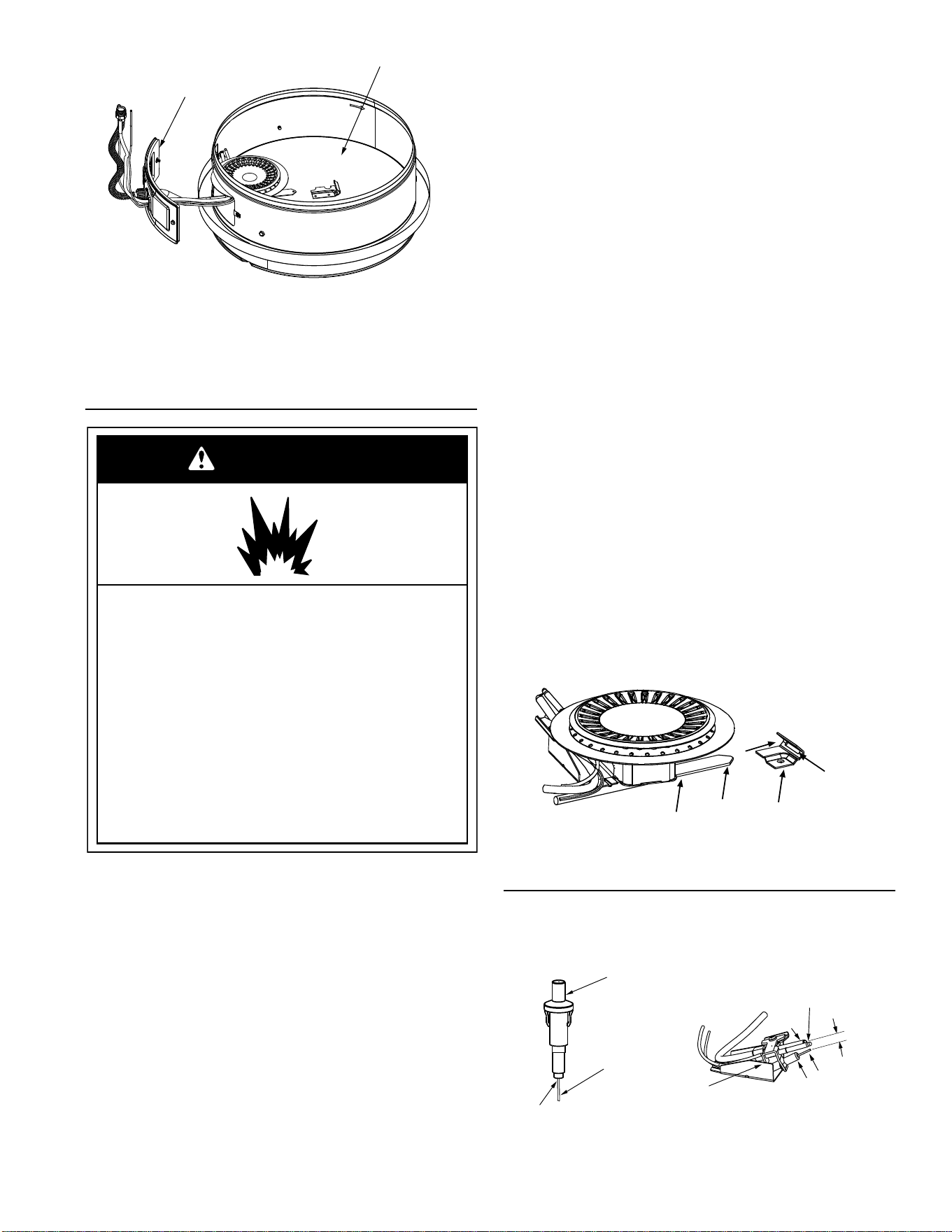
30
DOOR GASKET
COMBUSTION CHAMBER
FOR CLARITY, THE INLET AIR OPENING IS NOT SHOWN.
FIGURE 42.
REPLACING THE MANIFOLD/BURNER ASSEMBLY
WARNING
Explosion Hazard
Tighten both manifold door screws securely.
Remove any fiberglass between gasket and
combustion chamber.
Replace viewport if glass is missing or damaged.
removed.
Replace door gasket if damaged.
Failure to follow these instructions can result in
death, explosion, or fire.
Replace manifold component block if missing or
1. Check the door gasket for damage or imbedded debris prior to
installation (Figure 45).
2. Inspect the viewport for damage and replace as required
(Figure 40).
3. Insert the new manifold/burner assembly into the burner
compartment, making sure that the tab of the manifold tube
engages the slot of the bracket inside the combustion chamber
(Figure 46).
4. Inspect the door gasket and make sure there is no
fiberglass insulation between the gasket and the
combustion chamber (Figure 45).
5. Tighten the two screws that secure the manifold/burner
assembly to the combustion chamber. (Use a 1/4” SAE nut
driver.) There should be no space between the gasket part of
the manifold door and combustion chamber.
IMPORTANT: Do not operate the water heater if the door
gasket does not create a seal between the manifold door and
the combustion chamber.
6. Reconnect the manifold tube (3/4” SAE wrench) and pilot
tube (7/16” SAE wrench) to the gas control valve/thermostat
(Figure 39). Do not cross-thread or apply any thread sealant
to the fittings.
IMPORTANT: If you were supplied with a new ferrule
nut in a parts kit, follow these steps to connect the
pilot tube:
1.) Install the ferrule nut into the gas valve at the pilot tube
location, hand tight only. 2.) Insert the pilot tube into the ferrule
nut until the tube bottoms out, then tighten the nut with a 7/16”
SAE wrench until the crimp connection seals to the pilot tube.
3.) Continue to tighten until the nut is tight in the gas valve.
7. Connect the white and red wires to the gas control valve/
thermostat as shown in Figure 39.
8. Reconnect the igniter wire (Figure 39).
9. Turn on the gas supply to the water heater at the manual gas
shut-off valve (Figure 27).
10. Follow the lighting instructions on the front of the water heater.
With the main burner lit, check for leaks at the manifold and
pilot connections by brushing on an approved noncorrosive leak
detection solution. If such a solution is not available, use a mixture
of hand dish washing soap and water (one part soap to 15 parts
water) or children’s soap bubble solution. Bubbles forming indicate
a leak. Correct any leak found.
11. Verify proper operation, then replace the outer door.
MANIFOLD TUBE
TIP
BRACKET
SLOT
CLOSE-UP INSIDE VIEW OF
THE COMBUSTION CHAMBER.
FIGURE 43.
PIEZOELECTRIC IGNITER SYSTEM
The piezoelectric igniter system consists of the igniter button,
electrode, and wire. The pilot is ignited by an electric spark
generated when the igniter button is pressed. See Figure 44.
SNAP-ON CONNECTOR
IGNITER
BUTTON
WIRE
TO
ELECTRODE
THERMOCOUPLE
PILOT
PILOT
BRACKET
ELECTRODE
TIP
.125” *
* NOTE: SPARK GAP DISTANCE MEASURED FROM ELECTRODE TIP TO PILOT.
FIGURE 44.

31
TESTING THE IGNITER SYSTEM
Turn off the gas to the water heater at the manual gas shut-off valve.
Watch the electrode tip while activating the igniter. A visible spark
should jump from the electrode. To avoid shock, do not touch the burner
or any metal part on the pilot or pilot assembly. If no spark is visible,
check the wire connections and make sure the electrode is not broken.
Replace the igniter if defective. Dirt and rust on the pilot or electrode
tip can prevent the igniter spark. Wipe clean with a damp cloth and
dry completely. Rust can be removed from the electrode tip and metal
surfaces by lightly sanding with an emery cloth or fi ne grit sandpaper.
REMOVING AND REPLACING THE
G A S C O N T R O L VA LV E / T H E R M O S TAT
IMPORTANT: This gas control valve/thermostat is shipped from the
factory as a natural gas unit. However, it may be converted to use LP
gas. Before installing this gas control valve/ thermostat, make sure
that it is confi gured for the type of gas that you are using. Refer to the
“Gas Conversion” section.
Removing the Gas Control Valve/Thermostat:
1. Turn the gas control/temperature knob to the “OFF” position
(Figure 34).
2. Turn off the gas at the manual shut-off valve on the gas supply
pipe (Figure 27).
3. Drain the water heater. Refer to the section of “Draining and
Flushing” and follow the procedure.
4. Disconnect the igniter wire from the igniter lead wire. Use
needle nose pliers to disconnect the red (+) and white (-)
thermocouple wires. Disconnect the pilot tube (7/16” SAE
wrench) and manifold tube (3/4” SAE wrench) at the gas control
valve/thermostat. See Figure 36.
5. Refer to “Gas Piping” (Figure 27) and disconnect the ground
joint union in the gas piping. Disconnect the remaining pipe
from the gas control valve/thermostat.
6. To remove the gas control valve/thermostat, thread
a 4” (10.16 cm) section of gas pipe into the inlet and use it to turn
the gas control valve/thermostat (counterclockwise.) Do not use
a pipe wrench or equivalent to grip body. Damage may result,
causing leaks. Do not insert any sharp objects into the inlet or
outlet connections. Damage to the gas control valve/thermostat
may result.
Replacing the Gas Control Valve/Thermostat:
To replace the gas control valve/thermostat, reassemble in reverse
order. When replacing the gas control valve/thermostat, thread a 4”
(10.16 cm) section of gas pipe into the inlet and use it to turn the gas
control valve/thermostat (clockwise). DO NOT OVER TIGHTEN;
damage may result.
• Be sure to use approved Teflon
®
tape or pipe joint
compound on the gas piping connections and fitting on the
back of the gas control valve that screws into the tank.
• Be sure to remove the pilot ferrule nut from the new gas control
valve/thermostat.
• Turn the main gas supply on and check the gas supply
connections for leaks. Correct any leak found. Next, light
the pilot and main burner, then check the manifold tube and
pilot tube connections for leaks. Correct any leak found. Use
an approved noncorrosive leak detection solution. If such a
solution is not available, use a mixture of hand dish washing
soap and water (one part soap to 15 parts water) or children’s
soap bubble solution. Bubbles forming indicate a leak.
• Be sure tank is completely filled with water before lighting and
activating the water heater. Follow the “Lighting Instructions” on
the front of the water heater.
• If additional information is required, contact Residential
Technical Assistance.
TEFLON
®
is a registered trademark of E.I. Du Pont De
Nemours and Company.
SERVICE CHECKLIST
1. Manifold gasket properly sealed.
2. Viewport not damaged or cracked.
3. Manifold component block properly installed.
4. No leaks at pilot and manifold connection.
5. Manifold door screws securely tightened.
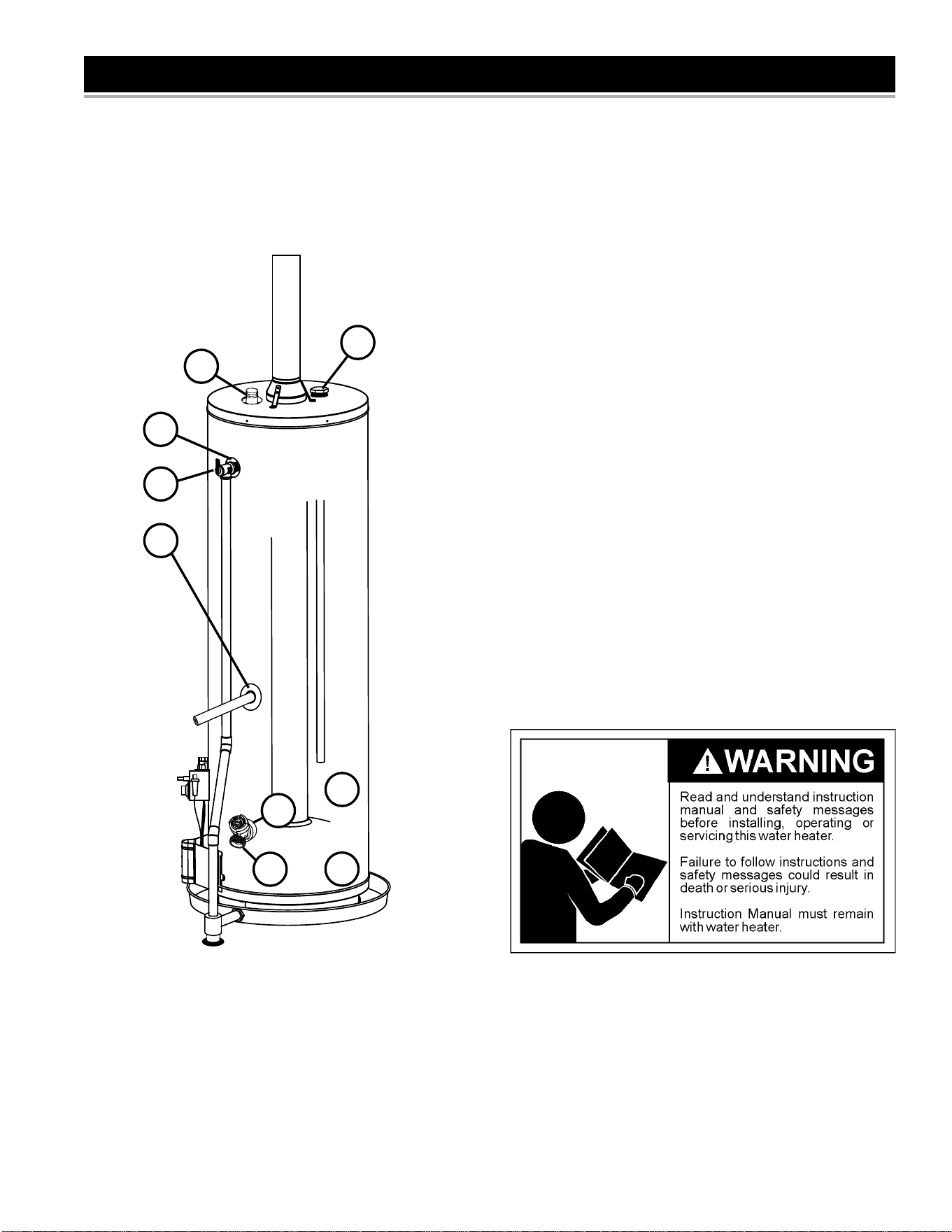
32
LEAKAGE CHECKPOINTS
A
B
A
C
D
E
F
G
H
FIGURE 45.
Use this guide to check a “Leaking” water heater. Many suspected
“Leakers” are not leaking tanks. Often the source of the water can
be found and corrected.
If you are not thoroughly familiar with gas codes, your water heater,
and safety practices, contact your gas supplier or qualifi ed installer to
check the water heater.
Read this manual fi rst. Then before checking the water heater make
sure the gas supply has been turned “OFF”, and never turn the gas
“ON” before the tank is completely full of water.
A. *Condensation may be seen on pipes in humid weather or pipe
connections may be leaking. NOTE: The location of the hot water
outlet has been modifi ed for clarity.
B. *The anode rod fi tting may be leaking. NOTE: The location of the
anode has been modifi ed for clarity.
C. Small amounts of water from temperature-pressure relief valve
may be due to thermal expansion or high water pressure in your
area.
D. *The temperature-pressure relief valve may be leaking at the
tank fi tting.
E. Water from a drain valve may be due to the valve being slightly
opened.
F. *The drain valve may be leaking at the tank fi tting.
G. Combustion products contain water vapor which can condense
on the cooler surfaces of the tank. Droplets form and drip onto
the burner or run on the fl oor. This is common at the time of
start-up after installation and when incoming water is cold.
H. Water in the water heater bottom or on the fl oor may be from
condensation, loose connections, or the relief valve. DO NOT
replace the water heater until a full inspection of all possible
water sources is made and necessary corrective steps taken.
Leakage from other appliances, water lines, or ground seepage
should also be checked.
* To check where threaded portion enters tank, insert cotton
swab between jacket opening and fi tting. If cotton is wet, follow
“Draining and Flushing” instructions in this manual and then
remove fi tting. Put pipe dope or Tefl on
®
tape on the threads and
replace. Then follow “Filling the Water Heater” instructions in
the “Installing the New Water Heater” section.
Tefl on
®
is a registered trademark of E. I. du Pont de Nemours and Company.

33
TROUBLESHOOTING GUIDELINES
PROBLEM POSSIBLE CAUSE(S) CORRECTIVE ACTION
BURNER WILL NOT IGNITE 1. Pilot not lit
2. Thermostat set too low
3. No gas
4. Dirt in the gas lines
5. Pilot line clogged
6. Main burner line clogged
7. Non-functioning thermocouple
8. Non-functioning thermostat
9. Heater installed in a confined area
1. Light pilot
2. Turn temp. dial to desired temperature
3. Check with gas utility company
4. Notify utility-install trap in gas line
5. Clean, locate source and correct
6. Clean, locate source and correct
7. Replace thermocouple
8. Replace thermostat
9. Provide fresh air ventilation
SMELLY WATER 1. Sulfides in the water 1. Replace the anode with a special anode
BURNER FLAME YELLOW-
LAZY
1. Insufficient secondary air
2. Low gas pressure
3. Water heater flue or vent system
blocked
4. Main burner line clogged
5. Heater installed in a confined area
6. Obstruction in main burner orifice
7. Incorrect gas conversion (if unit was
converted to use a different type of gas)
1. Provide ventilation to water heater
2. Check with gas utility company
3. Clean, locate source and correct
4. Clean, locate source and correct
5. Proper fresh air ventilation
6. Clean or replace orifice
7. Contact a qualified technician.
PILOT WILL NOT LIGHT OR
REMAIN LIT
1. Non-functioning igniter
2. The thermal switch tripped
3. Wire lead connection at thermal switch
loose
4. Thermocouple connection loose
5. Air in gas line
6. Low gas pressure
7. No gas
8. Dirt in gas lines
9. Cold drafts
10. Thermostat ECO switch open
11. Pilot line or orifice clogged
12. Non-functioning thermocouple
13. Air for combustion obstructed
14. Flammable vapors incident, FVIR
function actuated
15. Base-ring filter obstructed
1. Replace igniter pilot assembly
2. See Pilot Light Troubleshooting Flowchart section
3. Remove and reconnect the wire leads at
thermal switch, confirm connections are tight
and not loose
4. Finger tighten; then 1/4 turn with wrench
5. Bleed the air from the gas line
6. Check with gas utility company
7. Check with gas utility company
8. Notify utility-install dirt trap in gas line
9. Locate source and correct
10. Replace thermostat
11. Clean, locate source and correct
12. Replace thermocouple
13. See maintenance section for inspection and
cleaning of flame arrester
14. Replace water heater, eliminate flammable vapors
source. Contact Residential Technical Assistance.
15. Inspect and clean base-ring filter. See “External
Inspection & Cleaning of the Base-Ring Filter.”
HIGH OPERATION COSTS 1. Thermostat set too high
2. Sediment or lime in tank
3. Water heater too small for job
4. Wrong piping connections
5. Leaking faucets
6. Gas leaks
7. Wasted hot water
8. Long runs of exposed piping
9. Hot water piping in exposed wall
1. Set temperature dial to lower setting
2. Drain/flush-provide water treatment if needed
3. Install adequate heater
4. Correct piping-dip tube must be in cold inlet
5. Repair faucets
6. Check with utility-repair at once
7. Advise customer
8. Insulate piping
9. Insulate piping
INSUFFICIENT HOT WATER 1. Thermostat set too low
2. Sediment or lime in tank
3. Water heater too small
4. Wrong piping connections
5. Leaking faucets
6. Wasted hot water
7. Long runs of exposed piping
8. Hot water piping in outside wall
9. Low gas pressure
10. Incorrect gas conversion (if unit was
converted to use a different type of gas)
1. Turn temperature dial to desired setting
2. Drain/flush-provide water treatment if needed
3. Install adequate heater
4. Correct piping-dip tube must be in cold inlet
5 Repair faucets
6. Advise customer
7. Insulate piping
8. Insulate piping
9. Check with gas utility company
10. Contact a qualified technician.
SLOW HOT WATER
RECOVERY
1. Insufficient secondary air
2. Water heater flue or vent system
blocked
3. Low gas pressure
4. Improper calibration
5. Thermostat set too low
6. Water heater too small
7. Wrong piping connections
8. Wasted hot water
9. Incorrect gas conversion (if unit was
converted to use a different type of gas)
1. Provide ventilation to water heater. Check flue
way, flue baffle, and burner
2. Clean flue, locate source and correct
3. Check with gas utility company
4. Replace thermostat
5. Turn temperature dial to desired setting
6. Install adequate heater
7. Correct piping-dip tube must be in cold inlet
8. Advise customer
9. Contact a qualified technician.
34
PROBLEM POSSIBLE CAUSE(S) CORRECTIVE ACTION
DRIP FROM RELIEF VALVE 1. Excessive water pressure
2. Heater stacking
3. Closed water system
1. Use a pressure reducing valve and relief valve
2. Lower the thermostat setting
3. See “Closed System/Thermal Expansion”
THERMOSTAT FAILS TO
SHUT-OFF
1. Thermostat not functioning properly
2. Improper calibration
1. Replace thermostat
2. Replace thermostat
COMBUSTION ODORS 1. Insufficient secondary air
2. Water heater flue or vent system
blocked
3. Heater installed in a confined area
1. Provide ventilation to water heater. Check flue
way, flue baffle, and burner
2. Clean, locate source and correct
3. Provide fresh air ventilation
SMOKING AND CARBON
FORMATION (SOOTING)
1. Insufficient secondary air
2. Low gas pressure
3. Water heater flue or vent system
blocked
4. Thermostat not functioning properly
5. Heater installed in a confined area
6. Burner flame yellow-lazy
7. Incorrect gas conversion (if unit was
converted to use a different type of gas)
1. Provide ventilation to water heater. Check flue
way, flue baffle, burner
2. Check with gas utility company
3. Clean, locate source and correct
4. Replace thermostat
5. Provide fresh air ventilation
6. See “Burner Flame Yellow-Lazy”
7. Contact a qualified technician.
CONDENSATION 1. Temperature setting too low 1. Increase the temperature setting. Refer to the
“Condensation” sub-section in “Operational
Conditions.”
BURNER FLAME FLOATS
AND LIFTS OFF PORTS
1. Orifice too large
2. High gas pressure
3. Water heater flue or vent system
blocked
4. Cold drafts
5. Incorrect gas conversion (if unit was
converted to use a different type of gas)
1. Replace with correct orifice
2. Check with gas utility company
3. Clean flue and burner-locate source and correct
4. Locate source and correct
5. Contact a qualified technician.
BURNER FLAME TOO HIGH 1. Orifice too large
2. Incorrect gas conversion (if unit was
converted to use a different type of gas)
1. Replace with correct orifice
2. Contact a qualified technician.
FLAME BURNS AT ORIFICE 1. Thermostat not functioning properly
2. Low gas pressure
3. Incorrect gas conversion (if unit was
converted to use a different type of gas)
1. Replace thermostat
2. Check with gas utility company
3. Contact a qualified technician.
PILOT FLAME
TOO SMALL
1. Pilot line or orifice clogged
2. Low gas pressure
1. Clean, locate source and correct
2. Check with gas utility company
TROUBLESHOOTING GUIDELINES
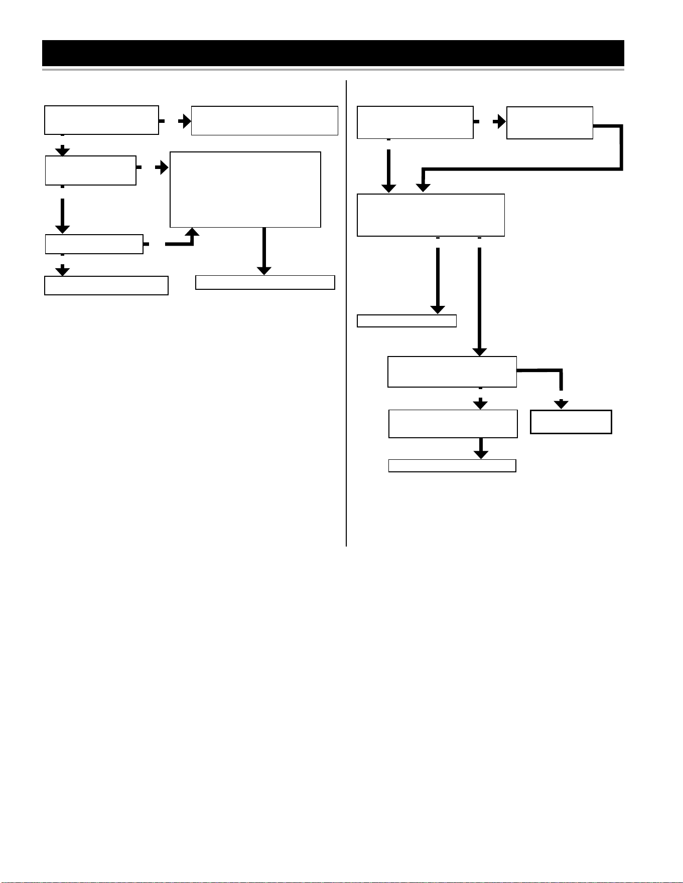
35
PILOT LIGHT TROUBLESHOOTING CHART
Have you bled all the air
from the pilot tube and
gas supply line?
NO
While repeatedly depressing the igniter
button, push in and hold the gas control/
temperature knob until the pilot is lit and
maintains a stable flame (status light will
blink). It may take up to 90 seconds of
pilot operation before status light blinks.
Once status light blinks, release the gas
control/temperature knob.
Section A: Pilot light will not light (new installation).
Is the manual gas shut-off valve,
located in the supply line to the
water heater, in the on position?
NO
YES
Turn the manual gas shut-off valve to
the on position and follow the lighting
instructions on the front of the water heater.
Is the igniter producing a
spark?
YES
NO
Follow the “Testing the Igniter
System” section in this manual.
YES
Set thermostat to desired temperature.
Section B: Pilot light repeatedly goes out.
Check the air intake for blockage.
Is the air intake clear of
obstructions ?
Clear the obstruction.
NO
YES
Does the diagnostic status light on the
gas control valve/thermostat give
a two flash error code?
Attempt to return the heater to service.
Does the pilot remain lit?
YES
Set to desired temperature.
NO
YES
Refer to the “Replacing the Pilot/Ther-
mopile Assembly” instructions in the
manual.
Reassemble and restore to service.
Contact Residential
Technical Assistance.
NO
NOTE: If you are still experiencing difficulties after following
the steps in sections A and B, please contact Residential
Technical Assistance.
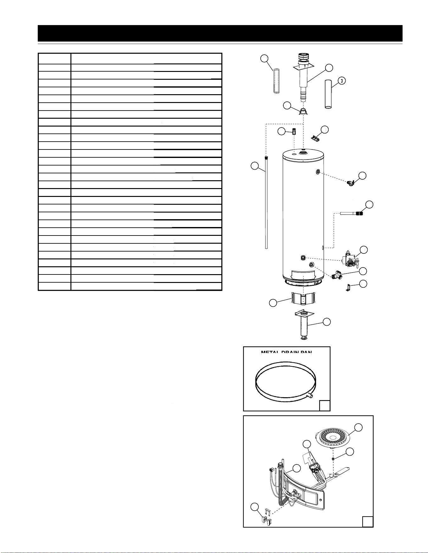
36
REPAIR PARTS LIST
MANIFOLD/BURNER ASSEMBLY
14
METAL DRAIN PAN
Key No. Part Description
1 10” Extension Pipe (Optional)
2 Air Duct Assembly (14.5” to 24” [36.8cm to 61cm] Long)
3 Angle Bracket
4 Angle Bracket (2 Required)
5 Anode Rod
6 Burner
7 Burner Orifi ce (Natural Gas)
7 Burner Orifi ce (Propane [L.P.] Gas)
8 Drain Valve
9 Gas Control Valve / Thermostat
10 Inlet Tube
11 Inner Door Gasket
12 Manifold Component Block w/ Clip
13 Manifold/Burner Assembly (Natural Gas)
13 Manifold/Burner Assembly (Propane [L.P.] Gas)
14 Metal Drain Pan
15 Nipple w/Heat Traps
#16 Optional 3” (76mm) Outside Wall Intake Air Vent Kit 9002986
#16 Optional 4” (102mm) Outside Wall Intake Air Vent Kit 9002987
17 Outer Door
18 Pilot Assembly with Tubing and Fittings
*19 Pipe Insulation
20 Roof Jack 12” / 30.48 cm (9002964005)
20 Roof Jack 32” / 81.28 cm (9002965005)
20 Roof Jack 60” / 152.4 cm (9002966005)
20 Roof Jack 95” / 241.3 cm (9002967005)
21 Flue Reducer
*22 T & P Insulation
23 Temperature-Pressure Relief Valve (T & P Valve)
* These parts available at most hardware stores.
# Not Shown.
Now that you have purchased this water heater, should a need ever exist
for repair parts or service, simply contact the company it was purchased
from or direct from the manufacturer listed on the rating plate on the
water heater.
Be sure to provide all pertinent facts when you call or visit.
Selling prices will be furnished on request or parts will be shipped
at prevailing prices and you will be billed accordingly.
The model number of your Gas Water Heater will be found on the rating
plate located above the gas control valve/thermostat.
WHEN ORDERING REPAIR PARTS, ALWAYS GIVE THE FOLLOWING
INFORMATION:
• MODEL NUMBER
• TYPE GAS (NATURAL OR PROPANE (L.P.)
• SERIAL NUMBER
• PART DESCRIPTION
THIS IS A REPAIR PARTS LIST, NOT A PACKING LIST.
1
19
20
15
3
5
23
22
10
9
8
4
2
17
21
1
4
METAL DRAIN PAN
MET
AL
DRA
IN
PAN
[36.8cm to 61cm] Lon
g)
G
a
s)
C
lip
u
ral
G
as)
p
ane [L.P.]
G
as
)
Intake Air Vent Kit 9002986
l
l Intake Air Vent Kit 900298
7
Fittin
g
s
9
64005
)
9
65005
)
9
66005
)
9
6700
5)
a
lv
e (
T
&
P Val
ve)
e
stores
.
e
r, should a need ever exist
c
ompan
y
it was purchased
o
n the ratin
g
plate on the
u call or visit.
t
or parts will be shipped
a
ccordin
g
l
y.
r
will be
f
ound on the ratin
g
r
mostat.
1
19
2
0
15
3
5
23
22
10
9
8
4
2
17
21
13
18
6
7
11
12

37
NOTES

38
NOTES

39
NOTES

40
Copyright © 2016 State Industries, Inc. All Rights Reserved.
