RESIDENTIAL GAS WATER HEATERS
Installation Instruction and Use & Care Guide
February, 2023
KEEP THIS MANUAL IN THE POCKET ON HEATER FOR FUTURE REFERENCE
WHENEVER MAINTENANCE ADJUSTMENT OR SERVICE IS REQUIRED.
POWER VENTED GAS MODELS
WITH HOT SURFACE IGNITION
NOT FOR USE IN MANUFACTURED (MOBILE) HOMES
• For Your Safety •
AN ODORANT IS ADDED TO THE GAS USED
BY THIS WATER HEATER.
DO NOT RETURN THIS UNIT TO THE STORE. To obtain technical, warranty, or service assistance during or after the installation
of this water heater, visit our website at: http:// www.AOSmithAtLowes.com or call toll free 1-877-817-6750.
100366722_2000622622_REV.A

TABLE OF CONTENTS
TABLE OF CONTENTS 2
SAFE INSTALLATION, USE AND SERVICE 3
GENERAL SAFETY 4
INTRODUCTION 6
QualiedInstallerOrServiceAgency ............ 6
PreparingForTheInstallation.................. 6
INSTALLATION REQUIREMENTS FOR THE
COMMONWEALTH OF MASSACHUSETTS 7
TYPICAL INSTALLATION 9
GetToKnowYourWaterHeater-GasModels
(ListReferencingFigures1-7).................. 9
ReplacementPartsAndDelimingProducts ...... 10
ComboHeatingInletAndOutletSideTaps ....... 10
WaterPiping-MixingValveUsage ..............11
MixingValves
WaterHeaterOperation ..................... 12
ElectricalRequirements&WiringDiagram ....... 13
SAFETYLOCKOUTS 14
HighLimitControls(EnergyCutO)............ 14
Thermostat/WaterTemperature
BlowerHighLimitSwitch
BlowerAirPressureSwitch ................... 14
FlammableVaporSensor .................... 14
LOCATINGTHENEWWATERHEATER 15
FactsToConsiderAboutTheLocation .......... 15
StorageOfFlammableLiquids ................ 15
Clearancestocombustibles
Floorswithcarpeting
Clearanceforservicing
InsulationBlankets ......................... 17
AirRequirements .......................... 17
UnconnedSpace.......................... 17
UnusuallyTightConstruction ................. 17
ConnedSpace............................ 17
DirectVentAppliances ...................... 18
ExhaustFans ............................. 18
FreshAirOpeningsForConnedSpaces........ 18
ChemicalVaporCorrosion ................... 19
INSTALLINGTHENEWWATERHEATER 20
WaterPiping .............................. 20
SpaceHeatingAndPotableWaterSystems...... 20
ComboHeating ............................ 21
SystemRequirements
Installation
ClosedWaterSystems ...................... 22
ThermalExpansion ......................... 22
Temperature-PressureReliefValve............. 23
T&Pvalvedischargepiperequirements:
Temperature-PressureReliefValveand
PipeInsulation
HighAltitudeInstallation ..................... 24
GasPiping................................ 24
SedimentTraps/DirtLeg ..................... 25
FillingTheWaterHeater ..................... 26
Venting .................................. 26
TerminationClearancesSidewallPowerVent..... 27
BlowerAssemblyInstallation.................. 28
InstallationOfVentSystem ................... 28
PlanningTheVentSystem ................... 28
HighAmbientTemperatureInstallations ......... 28
PolypropyleneVentSystems ................. 29
Condensate............................... 29
ExhaustVenting ........................... 30
ImportantNotesandWarnings
Ventingterminationsandsizing
Ventscreeninstallation
CalculatingEquivalentFeet
Ventinginstructions
Ventpipeconnectiontoblower
Dierentcouplinginstallationsaccording
toventsizes
BlowerExhaustDirection .................... 35
VentPipePreparation ....................... 35
InstallationChecklist ........................ 38
LIGHTING INSTRUCTIONS 39
OPERATING THE TEMPERATURE
CONTROLSYSTEM 40
GasControlValve/Thermostat ................ 41
FOR YOUR INFORMATION 42
StartUpConditions ......................... 42
Condensate
Thermalexpansion
Closedwatersystems
Smoke/odor
Strangesounds
OperationalConditions ...................... 42
Smellywater
“Air”InHot-WaterFaucets ................... 43
PERIODIC MAINTENANCE 44
GeneralUpkeep ........................... 44
VentingSystemInspection ................... 44
BlowerMaintenance ........................ 44
CleaningTheBlower. ....................... 44
BurnerOperationAndInspection .............. 45
CombustionChamberAndBurnerCleaning ...... 46
Housekeeping ............................. 46
AnodeRodInspection....................... 46
AnodeRod ............................... 46
RemovingAnodeRod:
InstallingAnodeRod:
Temperature-PressureReliefValveTest ......... 47
DrainingAndFlushing ....................... 48
Todrainthewaterheaterstoragetank:
Toushthewaterheaterstoragetank:
LEAKAGECHECKPOINTS 49
Service .................................. 49
REFERENCEPARTSLISTING 50
TROUBLESHOOTINGGUIDELINES 52
ResettingTheHeaterControl ................. 54
Lockouts ................................. 54
SoftLockout
HardLockout
IgnitionStateAndTiming .................... 55
SystemStatusAndErrorCodes ............... 55
LIMITEDWARRANTY 58
2
Your safety and the safety of others is extremely important in the installation, use and servicing of this water heater.
Many safety-related messages and instructions have been provided in this manual and on your own water heater to warn you and
others of a potential injury hazard. Read and obey all safety messages and instructions throughout this manual. It is very important
that the meaning of each safety message is understood by you and others who install, use or service this water heater.
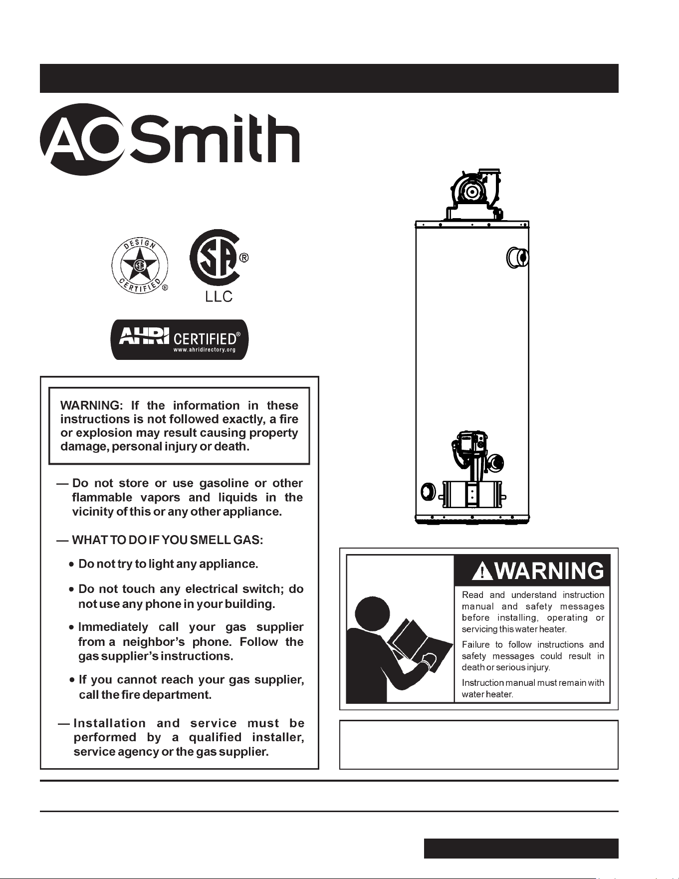
This is the safety alert symbol. It is used to alert you
to potential personal injury hazards. Obey all safety
messages that follow this symbol to avoid possible
injury or death.
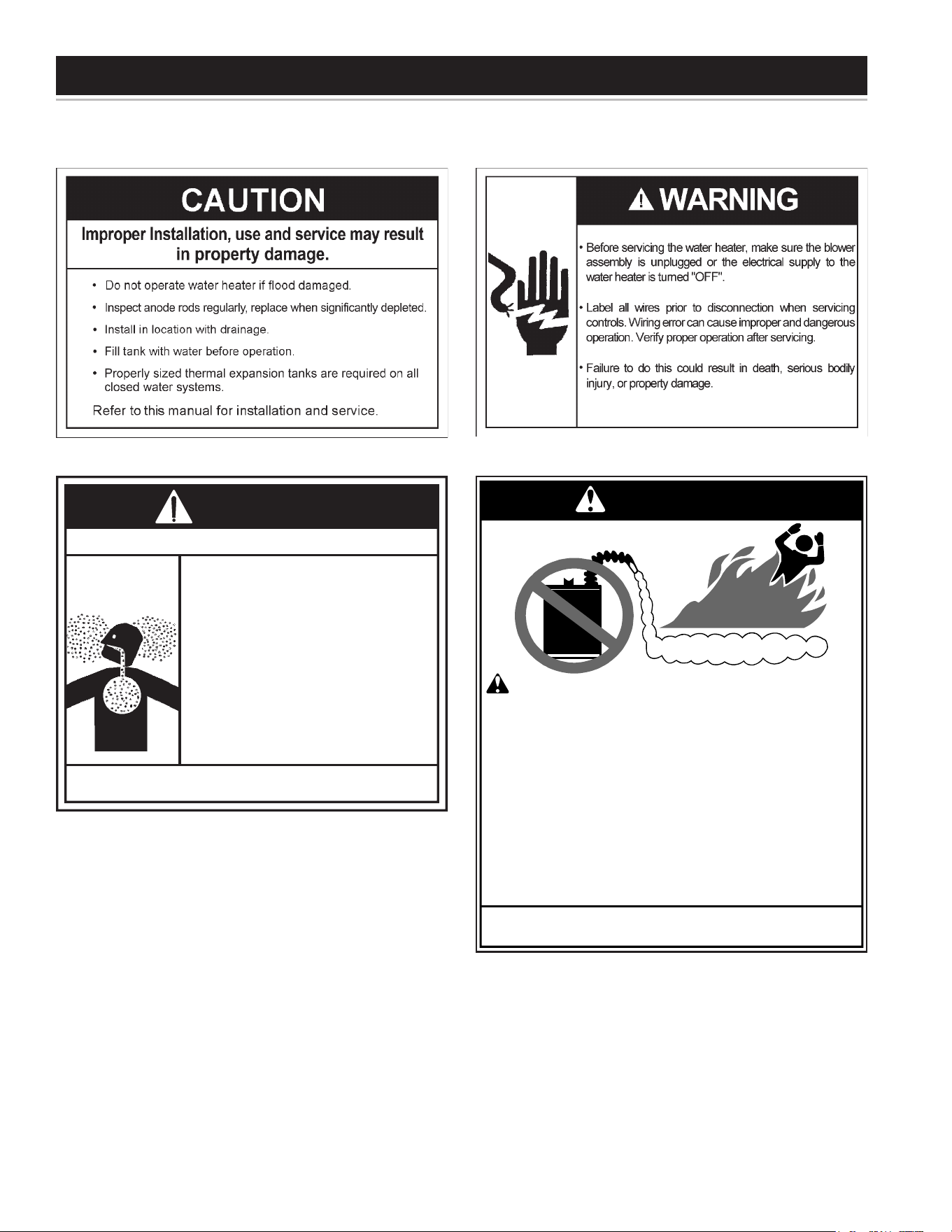
CAUTION used without the safety alert
symbol indicates a potentially hazardous
situation which, if not avoided, could
result in property damage
CAUTION indicates a potentially hazardous
situation which, if not avoided, could
result in minor or moderate injury.
WARNING indicates a potentially
hazardous situation which, if not avoided,
could result in death or injury.
DANGER indicates an imminently
hazardous situation which, if not avoided,
will result in death or injury.
CAUTION
WARNING
CAUTION
DANGER
All safety messages will generally tell you about the type of hazard, what can happen if you do not follow the safety message
and how to avoid the risk of injury.
The California Safe Drinking Water and Toxic Enforcement Act requires the Governor of California to publish a list of substances
known to the State of California to cause cancer, birth defects or other reproductive harm and requires businesses to warn
of potential exposure to such substances.
This product contains a chemical known to the State of California to cause cancer, birth defects or other reproductive harm.
This appliance can cause low level exposure to some of the substances listed in the Act.
IMPORTANT DEFINITIONS
Qualied Installer:Aqualiedinstallermusthaveabilityequivalenttoalicensedtradesmanintheeldsofplumbing,
airsupply,ventingandgassupply,includingathoroughunderstandingoftherequirementsoftheNationalFuelGas
Codeasitrelatestothe installation of gasredwaterheaters.Thequaliedinstallermustalso be familiar withthe
designfeaturesanduseofammablevaporignitionresistantwaterheatersandhaveathoroughunderstandingofthis
InstallationandOperatingmanual.
Service Agency:Aserviceagencyalsomusthaveabilityequivalenttoalicensedtradesmanintheeldsofplumbing,air
supply,ventingandgassupply,includingathoroughunderstandingoftherequirementsoftheNationalFuelGasCode
asitrelatestotheinstallationofgasredwaterheaters.Theserviceagencymustalsohaveathoroughunderstanding
ofthisInstallationandOperatingmanual,andbeabletoperformrepairsstrictlyinaccordancewiththeserviceguidelines
providedbythemanufacturer.
Gas Supplier:TheNaturalGasorPropaneUtilityorservicewhosuppliesgasforutilizationbythegasburningappliances
withinthisapplication.Thegassuppliertypicallyhasresponsibilityfortheinspectionandcodeapprovalofgaspiping
uptoandincludingtheNaturalGasmeterorPropanestoragetankofabuilding.Manygassuppliersalsooerservice
andinspectionofapplianceswithinthebuilding.
SAFE INSTALLATION, USE AND SERVICE
3
GENERAL SAFETY
4
GENERAL SAFETY
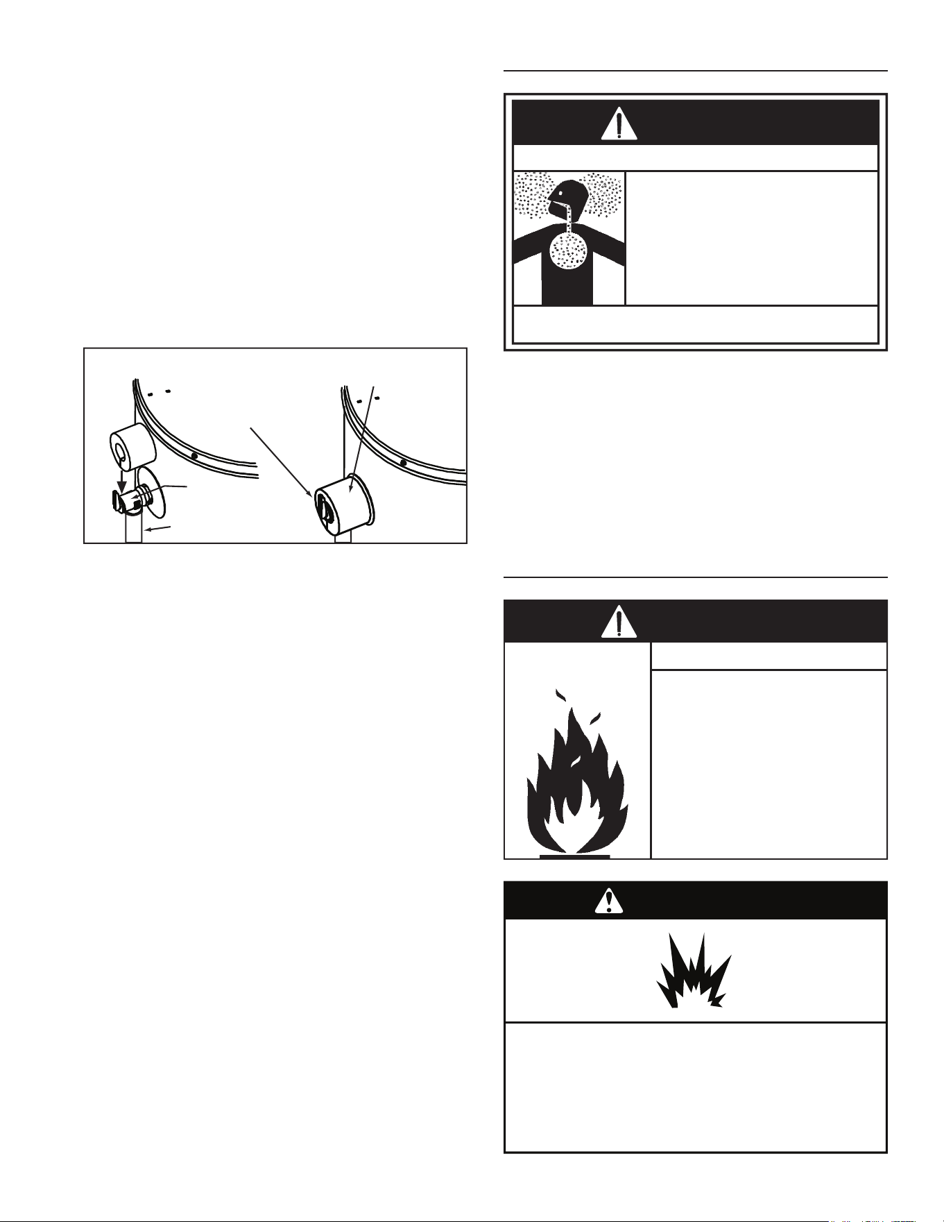
Installation: Do not install the water heater where flammable
products will be stored or used.
Vapors from flammable
liquids may explode and
catch fire causing death or
severe burns.
Do not use or store
flammable products such as
gasoline, solvents or adhe-
sives in the same room or
area near the water heater.
Keep flammable products:
1. far away from heater,
2. in approved containers,
3. tightly closed and
4. out of children's reach.
Water heater has a main
burner and hot surface igniter.
The hot surface igniter:
1. can be triggered at any
time and
2. the hot surface will ignite
flammable vapors.
Vapors:
1. cannot be seen,
2. are heavier than air,
3. go a long way on the floor
and
4. can be carried from other
rooms to the the
electodes by air currents.
Flammable Vapors
FLAMMBLE
DANGER
Breathing carbon monoxide can cause brain damage or death.
Always read and understand instruction manual.
• Install vent system in accordance with codes.
• Do not operate water heater if flood damaged.
• For operation above 10,100’, a high altitude
orifice must be installed.
• Do not operate if soot buildup is present.
• Do not obstruct water heater air intake with
insulating jacket.
• Do not obstruct blower air intake.
• Do not place chemical vapor emitting products
near water heater.
• Gas and carbon monoxide detectors are
available.
• No vent damper installation is compatible with
this power vented water heater.
Breathing Hazard - Carbon Monoxide Gas
WARNING
5

Thank You for purchasing this water heater. Properly
installedandmaintained,itshouldgiveyouyearsoftrouble
freeservice.
Abbreviations found in this Installation and Operating
manual:
• CSA-CanadianStandardsAssociation
• ANSI-AmericanNationalStandardsInstitute
• NFPA-NationalFireProtectionAssociation
• ASME-AmericanSocietyofMechanicalEngineers
• UL-UnderwritersLaboratoriesInc.
• AHRI -Air Conditioning, Heating and Refrigeration
Institute.
This gas-red water heater is design certied by CSA
International, under Water Heater Standard ANSI
Z21.10.1 • CSA 4.1(currentedition).
QUALIFIED INSTALLER OR SERVICE AGENCY
Installationandserviceofthiswaterheaterrequiresability
equivalentto thatof a QualiedAgency (asdened by
ANSIbelow)intheeldinvolved.Installationskillssuch
asplumbing,airsupply,venting,gassupplyandelectrical
supplyarerequiredinadditiontoelectricaltestingskills
whenperformingservice.
ANSI Z223.1 2006 Sec. 3.3.83:“QualiedAgency”-“Any
individual, rm, corporation or company that either in
personorthrougharepresentativeisengagedinandis
responsiblefor(a)theinstallation,testingorreplacement
ofgaspiping or(b)theconnection,installation,testing,
repair or servicing of appliances and equipment; that
is experienced in such work; that is familiar with all
precautionsrequiredand thathascompliedwithallthe
requirementsoftheauthorityhavingjurisdiction.”
Ifyouarenotqualied(asdenedbyANSIabove)and
licensed or certified as required by authority having
jurisdiction to perform a given task, do not attempt to
performanyoftheproceduresdescribedinthismanual.
If you do not understand the instructions given in this
manualdonotattempttoperformanyproceduresoutlined
inthismanual.
PREPARING FOR THE INSTALLATION
1. Readthe“GeneralSafetyInformation”sectionofthis
manualrstandthenentiremanualcarefully.Ifyou
don’t follow safety rules, the water heater will not
operateproperly.ItcouldcauseDEATH,SERIOUS
BODILY INJURYAND/OR PROPERTY DAMAGE.
This manual contains instructions for installation,
operation, and maintenance of the gas-red water
heater. It also contains warnings throughout the
manual that you must read and be aware of.All
warnings and instructions are essential to proper
operationofthewaterheaterandyoursafety.Since
we cannot put everything on the rst few pages,
READ ENTIRE MANUAL BEFORE ATTEMPTING
TO INSTALL OR OPERATE THE WATER HEATER.
2. Theinstallationmustconformwiththeseinstructions
andlocalcodeauthorityhavingjurisdiction.Inabsence
oflocalcodes,installationmustcomplywithcurrent
editionsoftheNationalFuelGasCode,ANSIZ223.1/
NFPA54andNationalElectricalCode,NFPA70.All
documentsareavailablefrom:
CSAInternational,
8501EastPleasantValleyRoad,
Cleveland,Ohio,UnitedStates
44131-5575.
NFPAdocumentsarealsoavailablefrom:
NationalFireProtectionAssociation,
1BatterymarchPark,
Quincy,MA02269.
3. Thewaterheater,wheninstalled,mustbeelectrically
groundedinaccordancewiththelocalcodesorinthe
absenceoflocalcodes:theNationalElectricalCode
(NFPA70).
4. Ifafterreadingthismanualyouhaveanyquestionsor
donotunderstandanyportionoftheinstructions,call
thelocalgasutilityorthemanufacturerwhosename
appearsontheratingplate.
5. Carefullyplantheplacewhereyouaregoingtoput
thewaterheater.Correctcombustion,ventaction,and
ventpipeinstallationareveryimportantinpreventing
deathfrompossiblecarbonmonoxidepoisoningand
res(seeFigure14&Figure15).Examinethelocation
toensurethewaterheatercomplieswiththe“Locating
theNewWaterHeater”sectioninthismanual.
6. ForinstallationinCalifornia,thiswaterheatermust
bebraced,anchored,orstrappedtoavoidfallingor
moving during an earthquake. See instructions for
correctinstallation procedures.Instructions maybe
obtainedfrom:
CaliforniaOceoftheStateArchitect,
400PStreet,
Sacramento,CA95814.
7. MassachusettsCoderequiresthiswaterheatertobe
installedInaccordancewithMassachusetts248-CMR
2.00:StatePlumbingCodeand248-CMR5.00.
8. Complies with California Health and Safety code
116875 (known asAB-1953) and with weighted
averagemaximumof0.25%lead.
INTRODUCTION
6

COMMONWEALTH OF MASSACHUSETTS
Forallsidewallterminated,horizontallyventedpowervent,directventandpowerdirectventgasfueledwaterheaters
installedineverydwelling,buildingorstructureusedinwholeorinpartforresidentialpurposes,includingthoseowned
oroperatedbytheCommonwealthandwherethesidewallexhaustventterminationislessthanseven(7)feetabove
nishedgradeintheareaoftheventing,includingbutnotlimitedtodecksandporches,thefollowingrequirementsshall
besatised:
INSTALLATION OF CARBON MONOXIDE DETECTORS
Atthetimeofinstallationofthesidewallhorizontalventedgasfueledequipment,theinstallingplumberorgasttershall
observethatahardwiredcarbonmonoxidedetectorwithanalarmandbatteryback-upisinstalledontheoorlevelwhere
thegasequipmentistobeinstalled.Inaddition,theinstallingplumberorgasttershallobservethatabatteryoperated
orhardwiredcarbonmonoxidedetectorwithanalarmisinstalledoneachadditionallevelofthedwelling,buildingor
structureservedbythesidewallhorizontalventedgasfueledequipment.Itshallbetheresponsibilityofthepropertyowner
tosecuretheservicesofqualiedlicensedprofessionalsfortheinstallationofhardwiredcarbonmonoxidedetectors.
Intheeventthatthesidewallhorizontallyventedgasfueledequipmentisinstalledinacrawlspaceoranattic,thehard
wiredcarbonmonoxidedetectorwithalarmandbatteryback-upmaybeinstalledonthenextadjacentoorlevel.
Intheeventthattherequirementsofthissubdivisioncannotbemetatthetimeofcompletionofinstallation,theowner
shallhaveaperiodofthirty(30)daystocomplywiththeaboverequirementsprovidedthatduringsaidthirty(30)day
period,abatteryoperatedcarbonmonoxidedetectorwithanalarmshallbeinstalled.
APPROVED CARBON MONOXIDE DETECTORS
EachcarbonmonoxidedetectorasrequiredinaccordancewiththeaboveprovisionsshallcomplywithNFPA720and
beANSI/UL2034listedandCSAcertied.
SIGNAGE
Ametalorplasticidenticationplateshallbepermanentlymountedtotheexteriorofthebuildingataminimumheight
ofeight(8)feetabovegradedirectlyinlinewiththeexhaustventterminalforthehorizontallyventedgasfueledheating
applianceorequipment.Thesignshallread,inprintsizenolessthanone-half(1/2)inchinsize,“GASVENTDIRECTLY
BELOW.KEEPCLEAROFALLOBSTRUCTIONS.”
INSPECTION
Thestateorlocalgasinspectorofthesidewallhorizontallyventedgasfueledequipmentshallnotapprovetheinstallation
unless,uponinspection,theinspectorobservescarbonmonoxidedetectorsandsignageinstalledinaccordancewith
theprovisionsof248CMR5.08(2)(a)1through4.
EXEMPTIONS
Thefollowingequipmentisexemptfrom248CMR5.08(2)(a)1through4:
1. TheequipmentlistedinChapter10entitled“EquipmentNotRequiredToBeVented”inthemostcurrenteditionof
NFPA54asadoptedbytheBoard;and
2. ProductApprovedsidewallhorizontallyventedgasfueledequipmentinstalledinaroomorstructureseparatefrom
thedwelling,building,orstructureusedinwholeorinpartforresidentialpurposes.
MANUFACTURERREQUIREMENTS-GASEQUIPMENTVENTINGSYSTEMPROVIDED
WhenthemanufacturerofProductApprovedsidewallhorizontallyventedgasequipmentprovidesaventingsystem
designorventingsystemcomponentswiththeequipment,theinstructionsprovidedbythemanufacturerforinstallation
oftheequipmentandtheventingsystemshallinclude:
1. Detailedinstructionsfortheinstallationoftheventingsystemdesignortheventingsystemcomponents;and
2. Acompletepartslistfortheventingsystemdesignorventingsystem.
MANUFACTURERREQUIREMENTS-GASEQUIPMENTVENTINGSYSTEMNOTPROVIDED
WhenthemanufacturerofProductApprovedsidewallhorizontallyventedgasfueledequipmentdoesnotprovidethe
partsforventingtheuegases,butidenties“specialventingsystems,”thefollowingrequirementsshallbesatisedby
themanufacturer:
1. Thereferenced“specialventingsystem”instructionsshallbeincludedwiththeapplianceorequipmentinstallation
instructions;and
2. The“specialventingsystems”shallbeProductApprovedbytheBoard,andtheinstructionsforthatsystemshall
includeapartslistanddetailedinstallationinstructions.
AcopyofallinstallationinstructionsforallProductApprovedsidewallhorizontallyventedgasfueledequipment,all
ventinginstructions,allpartslistsforventinginstructions,and/orallventingdesigninstructionsshallremainwiththe
applianceorequipmentatthecompletionoftheinstallation.
INSTALLATION REQUIREMENTS FOR THE COMMONWEALTH OF MASSACHUSETTS
7
IN
REMOVE A
MUST BE VERTICAL TO
IR BUBBLES
E
OUT
AIR
HANDLER
TO
AIR
HANDLER
SHUT-OFF
VALVE
*
EXPANSION TANK
VACUUM
RELIEF
VALVE
COLD WATER INLET
VA
FLOW CONTROL
LV
PUMP
*
SHUT-OFF
CHECK VALVE
†
(1/8” HOLE
DRILLED IN CLAPPER)
VALVE
CHECK
VALVE
†
TEMP/
PRESSURE
RELIEF
VALVE
TEMPERED WATER
TO FIXTURES
(MUST MEET TEMPS LISTED
IN MASS. CODE 248 CMR
†
)
MIXING VALVE
(MUST BE INSTALLED BELOW
TOP OF WATER HEATER
AS PER MANUFACTURER’S
RECOMMENDATIONS)
UNION
UNION
HOT
WATER
OUT
*
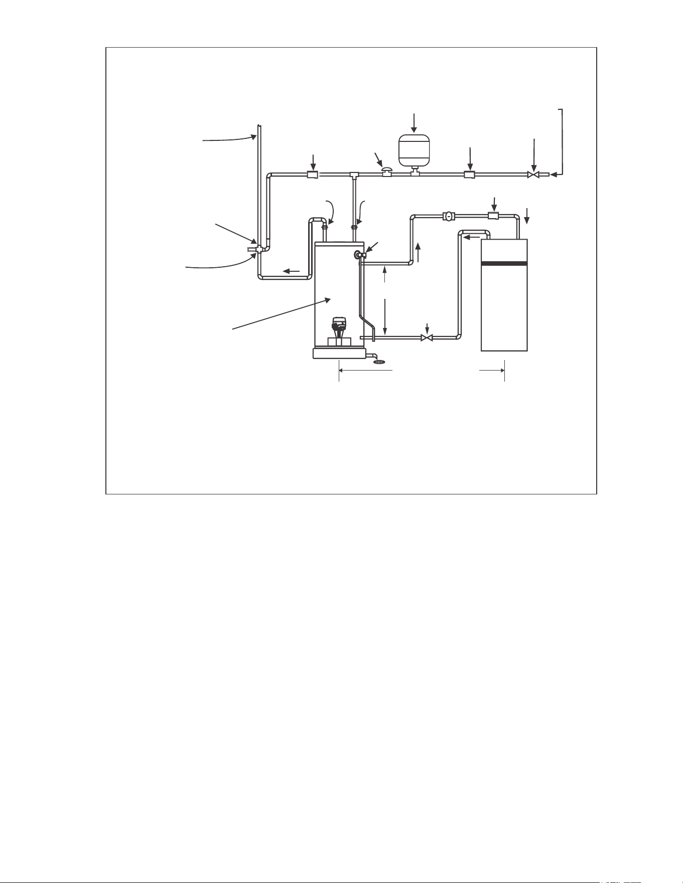
MASSACHUSETTS INSTALLATION REQUIREMENTS:
1.) CONNECT ELECTRONICALLY-CONTROLLED TIMER TO AN ALL-BRONZE PUMP. PUMP MUST ACTIVATE EVERY 6 HOURS
FOR 60 SECONDS. TURN PUMP TIMER OFF BEFORE CLOSING PIPING LOOP SHUT-OFF VALVE.
2.) ALL WATER PIPING MUST BE INSTALLED AND INSULATED IN ACCORDANCE WITH MASSACHUSETTS CODE (248 CMR
& 780 CMR).
3.) PIPING LOOP BETWEEN WATER HEATER AND AIR HANDLER MUST BE INSTALLED IN COMPLIANCE WITH 248 CMR.
† REQUIRED FOR MASSACHUSETTS.
‡ PIPING FROM THE TOP OF THE WATER HEATER WITH TEES IS ACCEPTABLE.
WATER HEATER ACCEPTED
BY THE BOARD FOR
INSTALLATION IN
MASSACHUSETTS.
†
TYPICAL MIXING VALVE INSTALLATION
COMBINATION SPACE HEATING / POTABLE WATER HEATING SYSTEM
SEE
NOTE ‡
100’-0” MAXIMUM DISTANCE
FROM WATER HEATER
TO FAN COIL AND BACK
(DEVELOPED LENGTH) NOT
INCLUDING COIL IN HEATING UNIT.
†
Some water heater models are equipped with inlet/outlet
connectionsforusewithspaceheatingapplications.Ifthis
waterheateristobeusedtosupplybothspaceheatingand
domestic potable (drinking) water, the instructions listed
belowmustbefollowed.
• This water heater is suitable for combination water
(potable)heatingandspaceheatingapplicationonly.
• Be sure to follow the manual(s) shipped with the air
handlersystem.
• Thiswaterheaterisnottobeusedasareplacementfor
anexistingboilerinstallation.
• Do not use with piping that has been treated with
chromates, boiler seal or other chemicals and do not
addanychemicalstothewaterheaterpiping.
• Ifthespaceheatingsystemrequireswatertemperatures
inexcessof120°F,installaThermostaticMixingValve
inthedomestic(potable)hotwatersupplyateachpoint-
of-usetolimittheriskofscaldinjury.Installthemixing
valveperthemanufacturersinstructions.
• Pumps,valves,piping,andfittingsmustbecompatible
withpotablewater.
• A properly installed flow control valve is required to
preventthermosiphoning.Thermosiphoningistheresult
of a continuous flow of water through the air handler
circuitduringtheoffcycle.
• Thedomestichotwaterlinefromthewaterheatershould
beverticalpastanymixingvalveorsupplylinetothe
air handler to remove air bubbles from the system.
Otherwise, these bubbles will be trapped in the air
handlerheatexchangercoil,reducingefficiency.
• Do not connect the water heater to any system or
components previously used with non-potable water
heatingapplianceswhenusedtosupplypotablewater.
Solar Installation
If this water heater is used as a solar storage heater
or as a backup for the solar system, the water supply
temperaturestothewaterheatertankmaybeinexcessof
120°F.AThermostaticMixingValveorothertemperature
limitingvalvemustbeinstalledinthewatersupplylineto
limitthesupplytemperatureto120°F.
NOTICE:Solarwaterheatingsystemscanoftensupply
waterwithtemperaturesexceeding180°Fandmayresult
inwaterheatermalfunction.
8
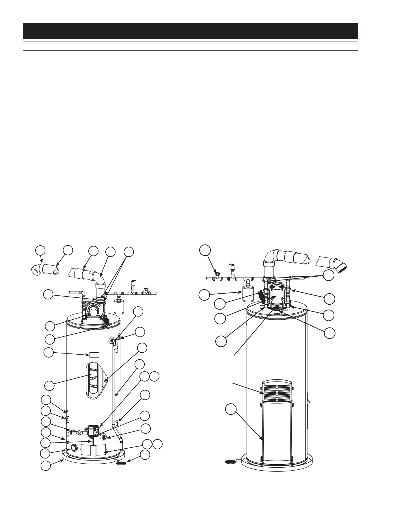
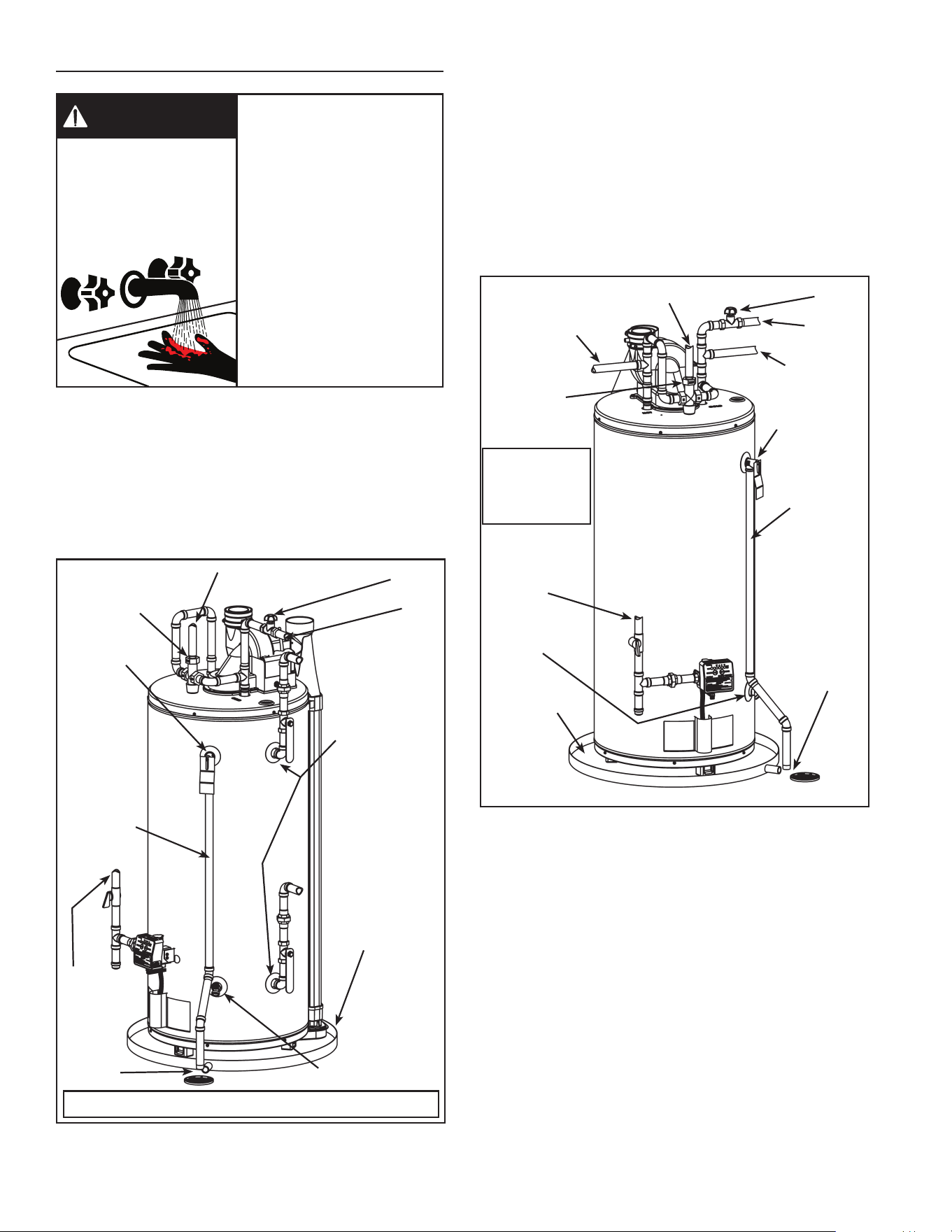
GET TO KNOW YOUR WATER HEATER - GAS MODELS (list referencing Figures 1-7)
TYPICAL INSTALLATION
1. VentTerminationElbowwithRodent
Screen
2. *VentPipe
3. *VentPipeCoupling(ifrequired)
4. *VentPipeElbow(longradius)
5. BlowerHighLimitSwitch(see
Figure6)
6. T&PValve
7. Cold-WaterInletNipple/Diptube
8. BaeAssembly
9. *DischargePipe
10.GasControlValve/Thermostat
(Honeywell/Resideo)
11.GasValveElectronicControl
ModuleAndCover(Honeywell/
Resideo)
12.DrainValve
13.OuterGasDoor
14.ManifoldDoorAssembly(behind
outerdoor)(seeFigure3&
Figure4)
15.*FloorDrain
16.*MetalDrainPan
17.FlammableVaporSensor(under
cover)(seeFigure5)
18.**ComboHeatingSystemReturn
Inlet(Optional)
19.AirInletSnorkel
20.**ComboHeatingSystemSupply
Outlet(Optional)
21.BlowerwithPowerCord(seealso
Figure6)
22.AirSwitch(insidebox)(see
Figure6)
23.JunctionBox(seeFigure6)
24.JunctionBoxCover(seeFigure6)
25.AirTubing(seeFigure6)
26.RubberCoupling(seealsoFigure
6)
27.GearClamp(seealsoFigure6)
28.FlueCollector
29.Hot-WaterOutletNipple
30.Anode(undercap)
31.***ControlHarness
32.FlexibleManifoldTube(see
Figure3&Figure4)
33.Viewport(seeFigure3&Figure4)
34.FlameSensorRod(seeFigure3&
Figure4)
35.GasOrice(seeFigure3&
Figure4)
36.SheetMetalBurner(seeFigure3&
Figure4)
37.GasManifold(seeFigure3&
Figure4)
38.Hot-SurfaceIgniter(seeFigure3&
Figure4)
39.ManifoldDoorGasket(seeFigure3
&Figure4)
40.ManifoldDoor(seeFigure3&
Figure4)
41.TwoPieceGrommetWithClip(see
Figure3&Figure4)
42.*InletWaterShut-oValve
43.*GasSupply*
44.*MainManualGasShut-oValve
45.*GroundJointUnion(gas
connection)
46.*SedimentTrap/DirtLeg
47.*Union(waterconnection)
48.RatingPlate
49.*ThermalExpansionTank(required
forallclosedsystems)
*,**,***,****seenotesonfollowing
page
FrontView RearView
Figure 1. Figure 2.
1
6
9
10
31
13
16
17
20
18
2
3
4
21
27
21
8
7
14
11
15
26
43
44
45
46
32
48
12
19
28
29
7
30
Combustion
AirInlets
27
42
47
47
49
Blower
DilutionAir
Inlets
9
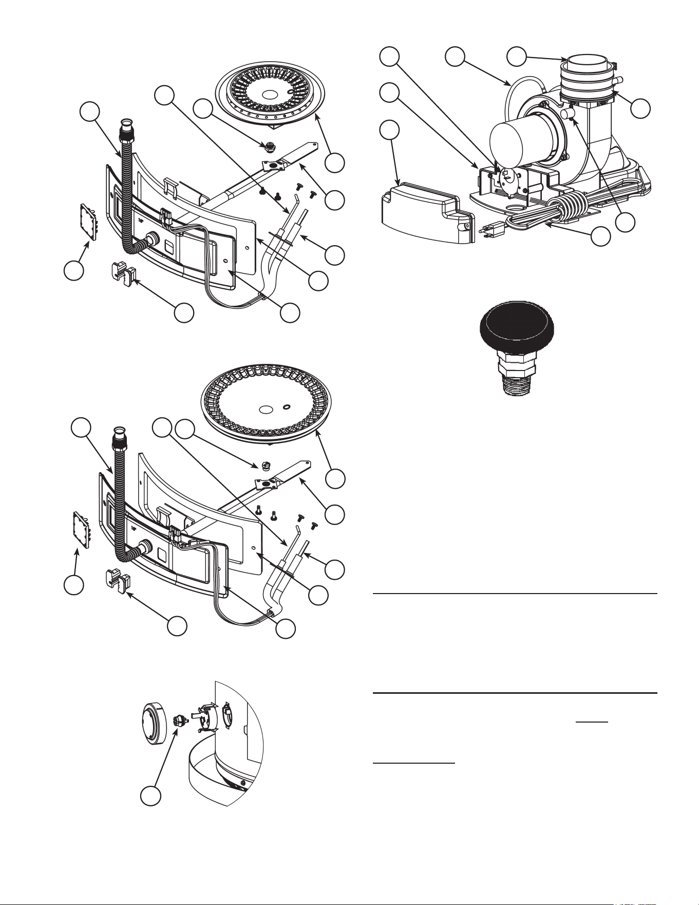
32
34
36
33
38
39
37
35
40
41
NaturalgasandPropanemain
burnerwithigniterassemblyfor
40kto50kBtu/hrmodels
Figure 3.
32 34
36
33
38
39
37
35
40
41
NaturalgasandPropane
mainburnerwithigniter
assemblyfor60kto75k
Btu/hrmodels
Figure 4.
17
Figure 5.
25
23
24
22
5
26
27
21
Figure 6.
Vacuumreliefvalve
installperlocal
codes(notsupplied
withheater).
Figure 7.
Notes:
* Itemsnotsuppliedwiththewaterheater.
** Thesiderecirculationloopconnectionsmaynotbe
usedastheprimarywaterinletandoutletconnections.
See “Combo Heating InletAnd Outlet Side Taps”
below.
*** Cautionharnesshas120VACInoperation.
****See“PlanningTheVentSystem”,“Condensate”and
“BlowerAssemblyInstallation”formoreinformation.
REPLACEMENT PARTS AND DELIMING PRODUCTS
Replacement parts and recommended delimer may be
orderedthroughauthorizedservicersordistributors.When
orderingparts,providecompletemodelandserialnumbers
(see rating plate), quantity and name of part desired.
Standardhardwareitemsmaybepurchasedlocally.
COMBO HEATING INLET AND OUTLET SIDE TAPS
Models equipped with Combo Heating capabilities are
shippedwiththetwosideplumbingtapsOPEN(items18
and20inFigure1andseealsoFigure8).Iftheheateris
tobeoperatedwithoutusingthesidetaps,theseopenings
must be closedwiththetwopipeplugssuppliedwiththe
heaters.
10
WATER PIPING - MIXING VALVE USAGE
Mixing Valves
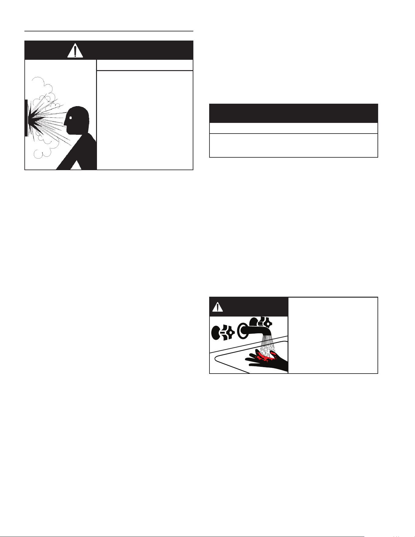
Water temperature over
125°F can cause severe
burns instantly resulting in
severe injury or death.
Children, the elderly and the
disabled and are at highest
risk of scald injury.
Feel water before bathing or
showering.
Temperature limiting devices
such as mixing must be
installed when required by
codes and to ensure safe
temperatures at fixtures.
BURN
HOT
HOT
DANGER
Water heated to a temperature which satises space
heating, clothes washing, dish washing, and other
sanitizingneedscanscaldandcausepermanentinjury
uponcontact.Shortrepeatedheatingcyclescausedby
smallhot-waterusescancauseatemperatureincreaseof
thehotwaterby30F°higherthantheheater’stemperature
settings. If you choose a higher temperature setting,
ThermostaticMixingValveslocatedateachpoint-of-use
areparticularlyimportanttohelpavoidscalding.
MIXING VALVE
SHUT-OFF
VALVE
SUGGESTED PIPING
ARRANGEMENT FOR
TOP CONNECTIONS
COLD-WATER
INLET
TEMPERED
POTABLE WATER
DISCHARGE
PIPE (DO NOT
CAPORPLUG)
GAS
SUPPLY
TEMPERATURE-
PRESSURE
RELIEF VALVE
DRAIN
VALVE
METAL DRAIN
PAN1.75”
MAX. DEPTH.
ATLEAST2”
GREATER THAN
THE DIAMETER
OF THE WATER
HEATER.
6”MAX.
AIR GAP*
CERTAIN
MODELS ARE
EQUIPPED WITH
SIDE PLUMBING
CONNECTIONS
FOR SPACE
HEATING. THE HOT
AND COLD FITTING
ASSEMBLIES
(PART#9001262)
CAN BE ORDERED
THROUGH THE
MANUFACTURER
*NOTE:THE
T&PVALVE
DISCHARGE
PIPE MUST
BE PIPED
DIRECTLY TO
THE DRAIN
OR EXTERNAL
TO THE
BUILDING
MASSACHUSETTS:INSTALLAVACUUMRELIEFINCOLDWATERLINE
PERSECTION19MGL142.
Figure 8.
his appliance has been design certied as complying
withAmericanNationalStandard/CSAStandardforwater
heatersandcertainmodelswithsideplumbingconnections
areconsideredsuitableforWater(Potable)Heatingand
SpaceHeating.Note:Donotuseinspaceheatingonly
applications.
Thewatersupplypressureshouldnotexceed80psi.Ifthis
occurs,apressurereducingvalvewithabypassshouldbe
installedinthecoldwaterinletline.Thisshouldbeplaced
onthesupplytotheentirehouseinordertomaintainequal
hotandcoldwaterpressures.
MIXING VALVE
SHUT-OFF
VALVE
SUGGESTED PIPING
ARRANGEMENT FOR
TOP CONNECTIONS
COLD-WATER
INLET
TEMPERED
POTABLE WATER
DISCHARGE
PIPE (DO NOT
CAPORPLUG)
GAS
SUPPLY
TEMPERATURE-
PRESSURE
RELIEF VALVE
DRAIN
VALVE
METAL DRAIN
PAN1.75”MAX.
DEPTH. AT
LEAST
2”GREATER
THAN THE
DIAMETER OF
THE WATER
HEATER.
6”MAX.
AIR GAP*
*NOTE:THE
T&PVALVE
DISCHARGE PIPE
MUST BE PIPED
DIRECTLY TO
THE DRAIN OR
EXTERNAL TO
THE BUILDING
MASSACHUSETTS:
INSTALL A VACUUM
RELIEF IN COLD
WATER LINE PER
SECTION19MGL
142.
NON-TEMPERED
WATER SUPPLY
NON-TEMPERED
WATER RETURN
Figure 9.
11
Somepeoplearemorelikelytobepermanentlyinjured
by hot water than others. These include the elderly,
children,theinrmandthephysically/mentallydisabled.
Table 1 (published by U.S. Government Memorandum,
1978) shows the approximate time-to-burn relationship
fornormaladultskin.Ifanyoneusinghotwaterprovided
bythewaterheaterbeinginstalledtsintooneofthese
groupsorifthereisalocalcodeorstatelawrequiringa
certainwatertemperatureatthepointofuse,thenspecial
precautionsmustbetaken.
Water
Temperature
°F
Time for 1st
Degree Burns
(Less Severe Burns)
Time for Permanent
Burns 2nd & 3rd
Degree (Most
Severe Burns)
110 (normalshowertemp.)
116 (painthreshold)
116 35minutes 45minutes
122 1minute 5minutes
131 5seconds 25seconds
140 2seconds 5seconds
149 1second 2seconds
154 instantaneous 1seconds
(U.S.GovernmentMemorandum,C.P.S.C.,PeterL.Armstrong,
Sept.15,1978)
Table 1.
In addition to using lowest possible temperature
setting that satises demand of application, to reduce
the risk of scalding, install Thermostatic Mixing Valve
(temperaturelimitingvalves)ateachpoint-of-use.These
valvesautomaticallymixhotandcoldwater to limitthe
temperatureatthetap.
ThermostaticMixingValvesareavailablefromyourlocal
plumbingsupplier.ConsultaQualiedInstallerorService
Agency.Followmixingvalvemanufacturer’sinstructions
forinstallationofthevalves.Beforechangingthefactory
setting on the thermostat, read the “Operating The
TemperatureControlSystem”sectioninthismanual.
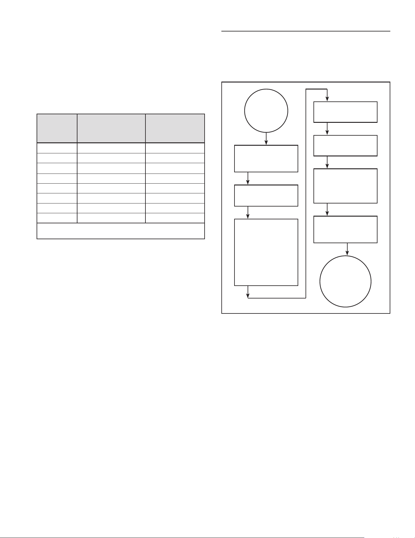
WATER HEATER OPERATION
Figure10showsthewaterheater’ssequenceofoperation
whenacallforheatisinitiated.Theignitioncontrolmodule
willattempttolighttheburnerthreetimes.Iftheignition
controldoesnotdetectignitionitwillenterlockoutmode
andashthecorrespondingerrorcode.
HEATER CONTROL
CHECKSTOENSURE
BLOWER PRESSURE
SWITCH IS OPEN
BLOWER IS
ENERGIZED
CONTROLCHECKS
TO ENSURE PRES-
SURE SWITCH CLOSES
INDICATING BLOWER
IS OPERATING AND
THERE ARE NO
VENTINGBLOCKAGES
(INLETOROUTLET)
IGNITERISENERGIZED
AND MAIN GAS VALVE
IS OPENED
MAIN BURNER COMES
ON AND THE FLAME IS
SENSED BY CONTROL
MAIN BURNER CONTIN-
UES TILL THE WATER
INTHETANKREACHES
THERMOSTAT SETTING
MAIN BURNER SHUTS
OFF. BLOWER
CONTINUES FOR A
POST PURGE TIME
HEATER
THERMOSTAT
CALLS FOR
HEAT
HEATER
REMAINS ON
STANDBY UNTIL
NEXT CALL FOR
HEAT
Figure 10.
12
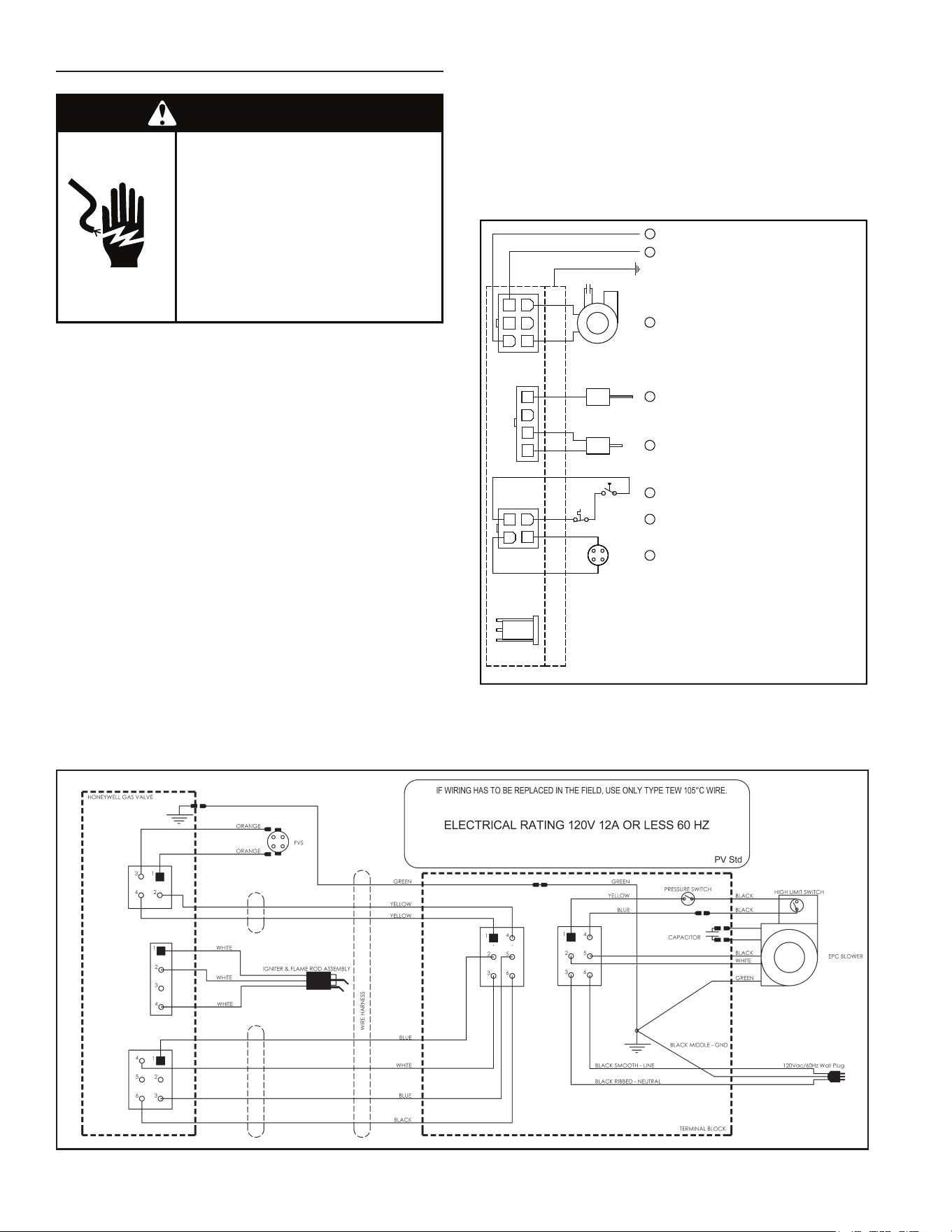
Figure 12.
ELECTRICAL REQUIREMENTS & WIRING DIAGRAM
Failure to do so can result in
death or electrical shock.
Replace all parts and panels
before operating.
Disconnect power before
servicing.
Electric Shock Hazard
WARNING
Beforeplugginginthewaterheater,alwaysmakesure:
• The voltage and frequency correspond to that
speciedonthewaterheaterwiringdiagram.
• Theelectricaloutlethastheproperoverloadfuseor
breakerprotection.
1. The unit must be connected to a dedicated power
supply.
2. The unit must be connected to a 120VAC power
supply.
3. Thewaterheatermustbeproperlygrounded.
4. Thiswaterheaterisapolaritysensitiveapplianceand
willnotoperateifthepowersupplypolarityisreversed.
Note:Alwaysreferencethewiringdiagramforthecorrect
electricalconnections.
Aftermakingallelectricalconnections,completelyllthe
tankwithwaterandcheckallconnectionsforleaks.Open
thenearesthot-waterfaucetandletitrunfor3minutesto
purgethewaterlinesofairandsedimentandtoensure
completellingofthetank.Theelectricalpowermaythen
beturnedon.Verifyproperoperationafterservicing.See
also“InstallationChecklist”.
CAUTION
LABEL ALL WIRES PRIOR TO DISCONNECTION WHEN
SERVICING CONTROLS. WIRING ERRORS CAN
CAUSE IMPROPER AND DANGEROUS OPERATION.
VERIFY PROPER OPERATION AFTER SERVICING.
POWER VENT WIRING SCHEMATIC.
NOTE: REFER TO THE “INSTALLATION CHECKLIST”
BEFORE OPERATING THIS HEATER.
N
1
2
3
HOT SURFACE IGNITER
HIGH LIMIT SWITCH
CAPACITOR
L1
EARTH GND
PRESSURE SWITCH
BLOWER
4
5
6
4
3
2
1
2
1
3
4
FLAME SENSOR
FLAMMABLE VAPOUR SENSOR
P1
P2
P3
4
6
1
5
3
2
7
Circled numbers indicate
sequence of operation.
P4
1
Figure 11.
13
Thiswaterheaterhasseverallockoutfeaturesdesigned
topreventtheheaterfromoperatinginunsafeconditions.
HIGH LIMIT CONTROLS (Energy Cut O)
Thermostat/Water Temperature
Thisfeatureisapartofthegascontrolvalve/thermostat
(see Figure 1, item 10) and limits the maximum water
temperature.Intheeventofthewateroverheating,this
safetyfeatureshutsothefuelsupplytotheburner.
Blower High Limit Switch
Thisdeviceislocatedontheblower(seeFigure6,item
5) and limits the maximum temperature of the blower.
If the blower temperature rises above the temperature
setting,theswitchopenscausingtheheatertoshutdown.
The switch will auto reset once the temperature drops
suciently.
BLOWER AIR PRESSURE SWITCH
Thisdevice,locatedinthejunctionbox,monitorstheair
pressureproduced bythe blower. In theevent thatthe
exhaustventingbecomesblockedorsucientlyrestricted,
theswitchwillshuttheheaterdown(seeFigure6,item22).
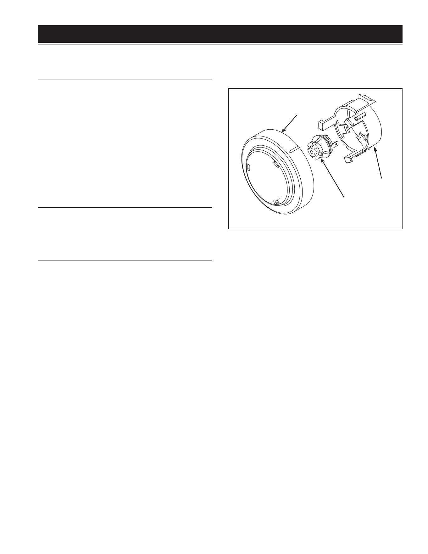
FLAMMABLE VAPOR SENSOR
When using a gas red water heater there is a risk of
ammablevaporsenteringthecombustionchamber,being
ignitedbytheburnerameandcausingaashback.In
ordertodetectsuchammablevaporsbeforetheyenter
thecombustionchamber, thiswaterheaterisequipped
witha ammable vaporsensor (FVS).Itis achemical-
absorption based sensor that is connected to the gas
control/thermostat (see Figure 13). When exposed to
ammable vapors it will trigger the control to stop the
owofgasandentertheFVSlockoutstate.Whileinthe
FVSlockout statethe LEDon the control will ash the
gaslockoutcode.(Refertothe“SystemStatusAndError
Codes”sectionofthismanualforanexplanationofthe
codes applicable to the control installed on your water
heater.)Ifthiserroroccurs,checkaroundthewaterheater
forsourcesofchemicalcontaminationsuchas:ammable
vaporsincludinggasvapors,solvents,paintandthinners
aswellassourcesofwateranddetergents.
Note:Resetting the heater will reset the FVIRcircuit if
allsourcesofcontaminationhavebeenremovedandthe
sensorclears.Ifallsourcesofcontaminationhavebeen
removedandthesystemwillnotreset,thesensorwillneed
tobereplaced(see“ResettingtheHeaterControl”).
If there is a problem with the wiring of the ammable
vaporsensorortheammablevaporinterface,theLED
willashthefailurestatuscode(see“SystemStatusAnd
ErrorCodes”).
MOUNTING
BRACKET
FLAMMABLE
VAPOR SENSOR
(PULLTOREMOVE)
COVER*
*ROTATELEFT(CCW)
TO REMOVE
Figure 13.
SAFETY LOCKOUTS
14
FACTS TO CONSIDER ABOUT THE LOCATION
Carefully choose an indoor location for the new water
heater because the placement is a very important
considerationforthesafetyoftheoccupantsinthebuilding
andforthemosteconomicaluseoftheappliance.This
waterheaterisnotforuseinmanufactured(mobile)homes
oroutdoorinstallation.
Whetherreplacinganoldwaterheaterorputtingthewater
heaterinanewlocation,thefollowingcriticalpointsmust
beobserved:
1. Select a location indoors as close as practical to
the vent termination or location to which the water
heaterventpipingisgoingtobeconnected,andas
centralizedwiththewaterpipingsystemaspossible.
2. Selectedlocationmustprovideadequateclearances
forservicingandproperoperationofthewaterheater.
3. Ensure the area hasa continuous supplyof air for
combustion,dilutionandventilation.
4. Avoidlocationsthatcouldcausethewaterheaterto
freezefromoutsideair.
5. Selectedlocationmustprovideaccesstoaproperly
groundedelectricalbranchcircuit.Adedicatedcircuit
ispreferred.DonotuseaGFIoutlet.
6. Avoidlocationsthatexposethewaterheatertodirect
sunlight.
7. Keep combustibles such as boxes, magazines,
clothes,etc.,awayfromthewaterheaterarea.
Important:Donotuseanextensioncordtoconnectthe
waterheatertoanelectricaloutlet.
Important:thisheaterhasspecialventingrequirements
wheninstalledinareaswheretheambienttemperatures
exceed 110°F (see “High Ambient Temperature
Installations”).
• All water heaters eventually leak.
• Do not install without adequate drainage.
Property Damage Hazard
CAUTION
Installationofthewaterheatermustbeaccomplishedin
suchamannerthatifthetankoranyconnectionsshould
leak, the ow of water will not cause damage to the
structure.Forthisreasonitisnotadvisabletoinstallthe
waterheaterinanatticorupperoor.Inallcases,ametal
drainpanshouldbeinstalledunderthewaterheater.Metal
drainpansareavailableatyourlocalhardwarestore.Such
ametaldrainpanmusthaveaclearanceofatleast1”
greaterthananypointonthewaterheater’souterjacket
andmustbepipedtoanadequatedrain.Thepanmust
haveamaximumdepthof1.75”.
Water heater life depends upon water quality, water
pressureandtheenvironmentinwhichthewaterheater
is installed. Water heaters are sometimes installed in
locationswhereleakagemayresultinpropertydamage,
evenwiththeuseofametaldrainpanpipedtoadrain.
However, unanticipated damage can be reduced or
preventedbyaleakdetectororwatershut-odeviceused
inconjunctionwithapipedmetaldrainpan.Thesedevices
are available from some plumbing supply wholesalers
andretailers,anddetectandreacttoleakageinvarious
ways:
• Sensorsmountedinthemetaldrainpanthattriggeran
alarmorturnotheincomingwatertothewaterheater
whenleakageisdetected.
• Sensorsmountedinthemetaldrainpanthatturno
thewatersupplytotheentirebuildingwhenwateris
detectedinthemetaldrainpan.
• Watersupplyshut-odevicesthatactivatebasedon
thewaterpressuredierentialbetweenthecold-water
andhot-waterpipesconnectedtothewaterheater.
• Devicesthatwillturnothegassupplytoagaswater
heater while at the same time shutting o its water
supply.
STORAGE OF FLAMMABLE LIQUIDS
Flammableliquids(suchasgasoline,solvents,propane
(LP or butane, etc.) and other substances (such as
adhesives,paints,etc.)emitammablevaporswhichcan
beignitedbyagaswaterheater’shotsurfaceigniter(HSI)
ormainburner.Theresultingashbackandrecancause
deathorseriousburnstoanyoneinthearea.
ThiswaterheaterisequippedwithaFV(FlammableVapor)
sensorfordetectingthepresenceofammablevapors.
Whenthesensordetectsthosevapors,theunitwillshut
downandnotoperate.Shouldthishappen,pleaserefer
tothe“TroubleshootingGuidelines”sectionofthismanual.
Even though this water heater is a ammable vapors
ignitionresistant(FVIR)waterheaterandisdesignedto
reducethechancesofammablevaporsbeingignited,
gasolineandotherammablesubstancesshouldnever
bestoredorusedinthesamevicinityorareacontaininga
gaswaterheaterorotheropenameorsparkproducing
appliance. Examples of such locations are garages,
storageandutilityareas.
Thewaterheatermustbelocatedand/orprotectedsoitis
notsubjecttophysicaldamagebyamovingvehicle.
LOCATING THE NEW WATER HEATER
15
Read instruction manual before
installing, using or servicing
water heater.
• Do not store or use gasoline or other flammable vapors and
liquids in the vicinity of this or any other appliance.
• Avoid all ignition sources if you smell gas.
• Do not expose water heater control to excessive gas
pressure.
• Use only gas shown on rating plate.
• Maintain required clearances to combustibles.
• Keep ignition sources away from faucets after extended
period of non-use.
Fire or Explosion Hazard
WARNING
323546-000
1. Turn the thermostat counter-clockwise to the lowest setting.
2. Set the gas control switch to the “OFF” position.
3. Turn off electrical power to the appliance if service is to be performed.
TO TURN OFF GAS TO APPLIANCE
1. STOP! Read the safety
information above on this
label.
2. Turn off all electric power to the
appliance.
3. Turn the thermostat
counter-clockwise to the
lowest setting.
4. Set the switch on the control to
the “OFF” position.
5. Do not attempt to light manually.
6. Wait five (5) minutes to clear out
any gas. If you then smell gas, STOP!
Follow “B” in the safety information above on
this label. If you don't smell gas, go the next
step.
7. Turn on all electric power to
the appliance.
8. Set the switch on the control
to the “ON” position.
9. Turn thermostat to desired
setting.
DANGER Hotter water
increases the risk of
scald injury. Consult the
instruction manual before
changing temperature.
10. If the appliance will not operate, follow the
instructions “To Turn Off Gas To Appliance”
and call your service technician or gas
supplier.
OPERATING INSTRUCTIONS
DANGER
A. This appliance does not have a pilot. It is
equipped with an ignition device which
automatically lights the burner. Do NOT try
to light the burner by hand.
B. BEFORE OPERATING smell all around the
appliance area for gas. Be sure to smell next
to the floor because some gas is heavier
than air and will settle on the floor.
WHAT TO DO IF YOU SMELL GAS:
• Do not try to light any appliance.
• Do not touch any electric switch; Do not use
any phone in your building.
• Immediately call your gas supplier from a
neighbor's phone. Follow the gas suppliers
instructions.
• If you cannot reach your gas supplier, call the
fire department.
C. Use only your hand to turn the gas control
buttons. Never use tools. If the control
buttons will not turn, don't try to repair them,
call a qualified service technician. Force or
attempted repair may result in a fire or
explosion.
D. Do not use this appliance if any part has
been under water. Immediately contact a
qualified installer or service agency to
replace a flooded water heater. Do not
attempt to repair the unit. It must be
replaced!
BEFORE OPERATING: ENTIRE SYSTEM MUST BE FILLED WITH WATER AND AIR PURGED FROM ALL LINES.
FLAMMABLEFLAMMABLE
WARNING: If you do not follow these instructions exactly, a fire
or explosion may result causing property damage, personal
injury or loss of life.
FOR YOUR SAFETY READ BEFORE LIGHTING
Read and follow water heater warnings and instructions in furnished manual.
If manual is missing, you may obtain one free of charge by calling 1-800-821-2017.
Si Ud. no puede ni leer ni entender el inglés y si necesita manuales, etiquetas
o rótulos en español, Ud. los puede obtener si al llama 1-800-821-2017.
WARNING / ADVERTENCIA
HOT
BURN
Water temperature over 125°F can
cause severe burns instantly or
death from scalds.
Children, disabled and elderly are
at highest risk of being scalded.
See instruction manual before
setting temperature at water heater.
Feel water before bathing or
showering.
Temperature limiting valves are
available, see manual.
DANGER
Do not store or use gasoline or other flammable vapors and
liquids in the vicinity of this or any other appliance. Storage or
use of gasoline or other flammable vapors or liquids in the
vicinity of this or any other appliance can result in serious injury
or death.
Can result in serious injury or death
FIRE AND EXPLOSION HAZARD
Flammable Vapors
FLAMMABLES
WARNING
For continued protection against
risk of fire:
• Do not install water heater on
carpeted floor.
• Do not operate water heater if
flood damaged.
Fire Hazard
WARNING
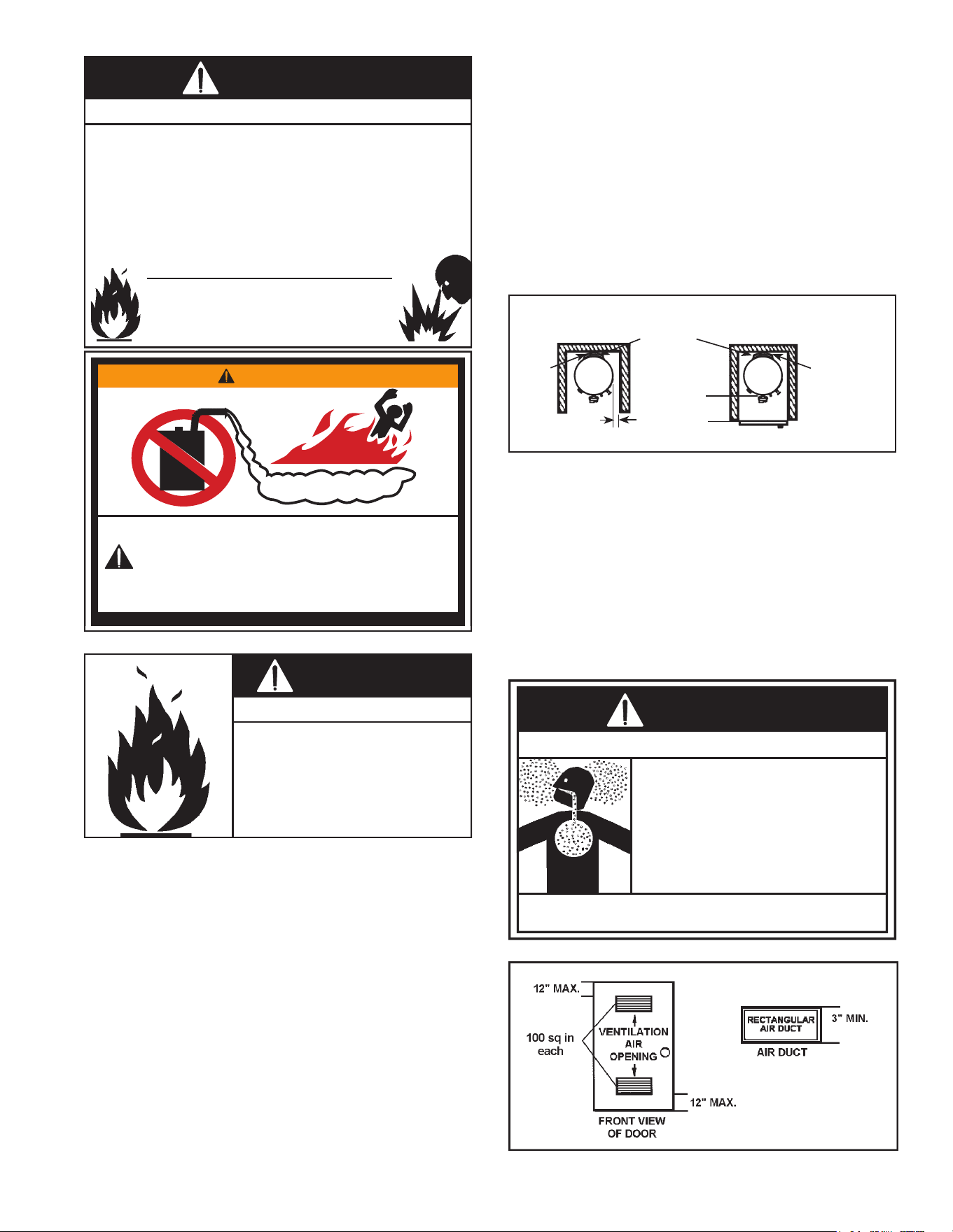
Clearances to combustibles
Minimum clearances between water heater and
combustiblesare0”atthesidesandrear,5.5”fromthe
frontand12”fromtop(standardclearance.)Ifclearances
statedontheheaterdierfromstandardclearances,install
waterheateraccordingtoclearancesstatedontheheater
(seeFigure14).
Floors with carpeting
This water heater must not be installed directly on
carpeting. Carpeting must be protected by a metal or
wood panel beneath the appliance extending beyond
thefullwidthanddepthoftheappliancebyatleast3”in
everydirection,oriftheapplianceisinstalledinanalcove
orcloset,theentireoormustbecoveredbythepanel.
Failuretoheedthiswarningmayresultinarehazard.
Clearance for servicing
Adequate clearance of 24” for servicing this appliance
shouldbeconsideredbeforeinstallation,suchaschanging
theanodes,etc.
Aminimumclearanceof5.5”mustbeallowedforaccess
toreplaceablepartssuchasthermostats,drainvalveand
reliefvalve.
Wheninstallingtheheater,considerationmustbegivento
properlocation.Locationselectedshouldbeascloseto
thewallaspracticableandascentralizedwiththewater
pipingsystemaspossible.
TOP VIEW
OF CLOSET
WITHOUT DOOR
AIR INTAKE*
TOP VIEW OF
CLOSET WITH
DOOR
0” MIN.
0” MIN. 0” MIN.
5.5” MIN.
* DO NOT BLOCK THE AIR INTAKES AT THE BACK OF THE WATER HEATER.
Figure 14.
Agaswaterheatercannotoperateproperlywithoutthe
correctamountofairforcombustionandventilation.Do
notinstallinaconnedareasuchasaclosetunlessyou
provide air as shown below and described in the “Air
Requirements”section(seeFigure15).Neverobstructthe
owofventilationairfordilutionandcombustion.Ifyou
haveanydoubtsorquestionsatall,callyourgassupplier.
Failureto provide theproper amount ofcombustion air
canresultinareorexplosionandcausedeath,serious
bodilyinjury,orpropertydamage.
Breathing carbon monoxide can cause brain damage or death.
Always read and understand instruction manual.
• Install water heater in accordance with the
instruction manual and NFPA54.
• To avoid injury, combustion and ventilation air
must be taken from outdoors.
• Do not place chemical vapor emitting products
near water heater.
Breathing Hazard - Carbon Monoxide Gas
WARNING
Figure 15.
16
Ifthiswaterheaterwillbeusedinbeautyshops,barber
shops,cleaningestablishments,orself-servicelaundries
withdrycleaningequipment,itisimperativethatthewater
heaterorwaterheatersbeinstalledsothatcombustion
andventilationairbetakenfromoutsidetheseareas.
Propellants of aerosol sprays and volatile compounds,
(cleaners,chlorinebasedchemicals,refrigerants,etc.)in
additiontobeinghighlyammableinmanycases,willalso
reacttoformcorrosivehydrochloricacidwhenexposedto
thecombustionproductsofthewaterheater.Theresults
canbehazardous,andalsocauseproductfailure.
INSULATION BLANKETS
Insulationblanketsareavailabletothegeneralpublicfor
externaluseongaswaterheatersbutarenotnecessary
withtheseproducts.Thepurposeofaninsulationblanketis
toreducestandbyheatlossencounteredwithstoragetank
heaters.Yourwaterheatermeetsorexceedsthecurrent
standards with respect to insulation and standby loss
requirements,makinganinsulationblanketunnecessary.
Should you choose to apply an insulation blanket to
this heater, you should follow these instructions (For
identicationofcomponentsmentionedbelow,seeFigure
1thruFigure7).Failuretofollowtheseinstructionswill
restrictthe air ow required forproper combustionand
dilution,potentiallyresultinginre,asphyxiation,serious
personalinjuryordeath.
• Donotapplyinsulationtothetopofthewaterheater,
asthiswillinterferewithsafeoperationoftheblower
assembly.
• Donotcovertheouterdoor,thermostatorT&Prelief
valve,FVsensor,orAirIntakeSnorkel.
• Donotcoverthe“InstallationAndOperatingmanual”.
Keepitonthesideofthewaterheaterornearbyfor
futurereference.
• Doobtainnewwarningandinstructionlabelsfromthe
manufacturerforplacementontheblanketdirectlyover
theexistinglabels.
• Doinspecttheinsulationblanketfrequentlytomake
certainitdoesnotsag,therebyobstructingcombustion
airow.
Breathing carbon monoxide can cause brain damage or death.
Always read and understand instruction manual.
• Do not obstruct water heater air intake(s) with
insulating jacket.
• Gas and carbcn monoxide detectors are available.
• Install water heater in accordance with the
instruction manual and NFPA54.
Breathing Hazard - Carbon Monoxide Gas
WARNING
AIR REQUIREMENTS
For safe operation an adequate supply of fresh,
uncontaminatedairforcombustion,dilutionandventilation
mustbeprovided.
Note:Contaminatedordustyairmaycausebuild-upon
theblowerwheelresultinginnuisanceshutdowns.
An insucient supply of air can cause recirculation of
combustionproductsresultingincontaminationthatmay
behazardoustolife.Suchaconditionoftenwillresultin
ayellow,luminousburnerame,causingsootingofthe
combustionchamber,burnersanduetubesandcreates
ariskofasphyxiation.
Donotinstallthewaterheaterinaconnedspaceunless
an adequate supply of air for combustion, dilution and
ventilationisbroughtintothatspaceusingthemethods
describedinthe“ConnedSpace”sectionthatfollows.
Never obstruct the ow of dilution/ventilation air. If you
haveanydoubtsorquestionsatall,callyourgassupplier.
Failuretoprovidetheproperamountsofaircanresultin
areorexplosionandcausepropertydamage,serious
bodily injury or death. The combustion and dilution air
inletsareshowninFigure2.
Important: Power Vented water heaters require air for
combustionanddilutionairfortheblower.
UNCONFINED SPACE
AnUnconnedSpaceisonewhosevolumeisnotlessthan
50cubicfeetper1,000Btu/hrofthetotalinputratingofall
appliancesinstalledinthespace.Roomscommunicating
directly with the space in which the appliances are
installed,throughopeningsnotfurnishedwithdoors,are
consideredapartoftheunconnedspace.
Makeup air requirements for the operation of exhaust
fans, kitchen ventilation systems, clothes dryers and
replacesshouldalsobeconsideredindeterminingthe
adequacyofaspacetoprovidecombustion,ventilation
anddilutionair.
UNUSUALLY TIGHT CONSTRUCTION
In unconned spaces in buildings, inltration may be
adequate toprovide air for combustion, ventilation and
dilutionofuegases.However,inbuildingsofunusually
tight construction (e.g., weather stripping, heavily
insulated,caulked,vaporbarrier,etc.)additionalairmust
beprovidedusingthemethodsdescribedinthe“Conned
Space”sectionthatfollows.
CONFINED SPACE
AConnedSpaceisonewhosevolumeislessthan50
cubicfeetper1,000Btu/hrofthetotalinputratingofall
appliancesinstalledinthespace.
Openings must be installed to provide fresh air for
combustion,ventilationanddilutioninconnedspaces.
Therequiredsizefortheopeningsisdependentonthe
methodusedtoprovidefreshairtotheconnedspace
17
andthetotalBtu/hrinputratingofallappliancesinstalled
inthespace.
DIRECT VENT APPLIANCES
OtherappliancesinstalledinaDirectVentconguration
that derive all air for combustion from the outdoor
atmosphere through sealed intake air piping are not
factored in the total appliance input Btu/hr calculations
usedto determine the size of openings providing fresh
airintoconnedspaces.
EXHAUST FANS
Whereexhaustfansareinstalled,additionalairshouldbe
providedtoreplacetheexhaustedair.Whenanexhaust
fan is installed in the same space with a water heater,
sucientopeningstoprovidefreshairmustbeprovided
that accommodate the requirements for all appliances
inthe roomand the exhaust fan. Undersized openings
will cause air to be drawn into the room through the
water heater’s vent system causing poor combustion.
Sooting,seriousdamagetothewaterheaterandtherisk
ofreorexplosionmayresult.Itcanalsocreateariskof
asphyxiation.
FRESH AIR OPENINGS FOR CONFINED SPACES
Thefollowinginstructionsshouldbeusedtocalculatethe
size,numberandplacementofopeningsprovidingfreshair
forcombustion,ventilationanddilutioninconnedspaces.
Theillustrationsshowninthissectionofthemanualare
a reference for the openings that provide fresh air into
connedspacesonly.Donotrefertotheseillustrations
for the purpose of vent installation. See “Installation of
Vent System” section for complete venting installation
instructions.
Chemicalvaporcorrosionoftheue,blowerassemblyand
ventsystemmayoccuriftheairsupplycontainscertain
chemicalvapors.Spraycanpropellants,cleaningsolvents,
refrigeratorandairconditionerrefrigerants,swimmingpool
chemicals,calciumandsodiumchloride(watersoftener
salt), waxes, bleach and process chemicals are typical
compoundswhicharepotentiallycorrosive.
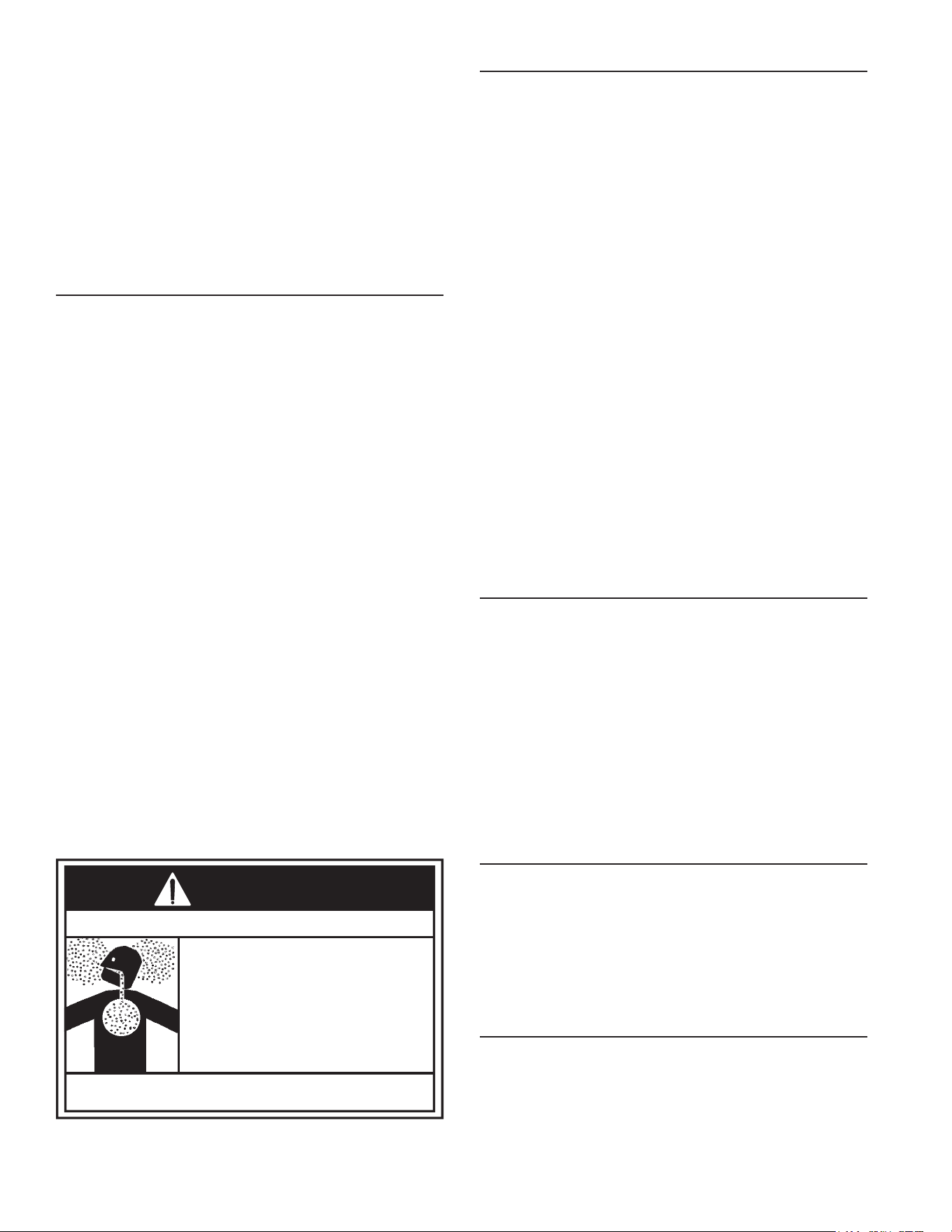
A.ALLAIRFROMINSIDEBUILDINGS:(SeeFigure16)
The confined space shall be provided with two
permanentopenings communicatingdirectly withan
additional room(s) of sucient volume so that the
combinedvolumeofallspacesmeetsthecriteriaforan
unconnedspace.Thetotalinputofallgasutilization
equipment installed in the combined space shall be
consideredinmakingthisdetermination.Eachopening
shallhaveaminimumfreeareaofonesquareinchper
1,000Btu/hrofthetotalinputratingofallgasutilization
equipmentintheconnedspace,butnotlessthan100
square inches.One opening shall commence within
12”ofthetopandonecommencingwithin12”ofthe
bottomoftheenclosures.
Figure 16.
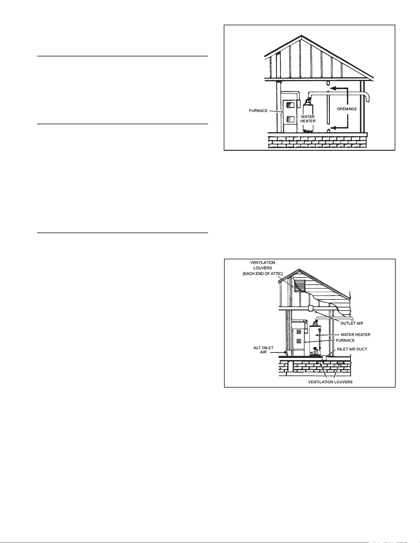
B.ALLAIR FROM OUTDOORS: (See Figure 17 thru
Figure19)
The confined space shall be provided with two
permanentopenings,onecommencingwithin12”ofthe
topandonecommencingwithin12“fromthebottom
of the enclosure. The openings shall communicate
directly,orbyducts,withtheoutdoorsorspaces(crawl
orattic)thatfreelycommunicatewiththeoutdoors.
1. When directly communicating with the outdoors,
eachopeningshallhaveaminimumfreeareaof1
squareinchper4,000Btu/hroftotalinputratingof
allequipmentintheenclosure(seeFigure17).
Figure 17.
2. When communicating with the outdoors through
verticalducts,eachopeningshallhaveaminimum
freeareaof1squareinchper4,000Btu/hroftotal
inputratingofallequipmentintheenclosure(see
Figure18).
3. When communicating with the outdoors through
horizontal ducts, each opening shall have a
minimumfreeareaof1squareinchper2,000Btu/hr
oftotalinputratingofallequipmentintheenclosure
(seeFigure19).
18
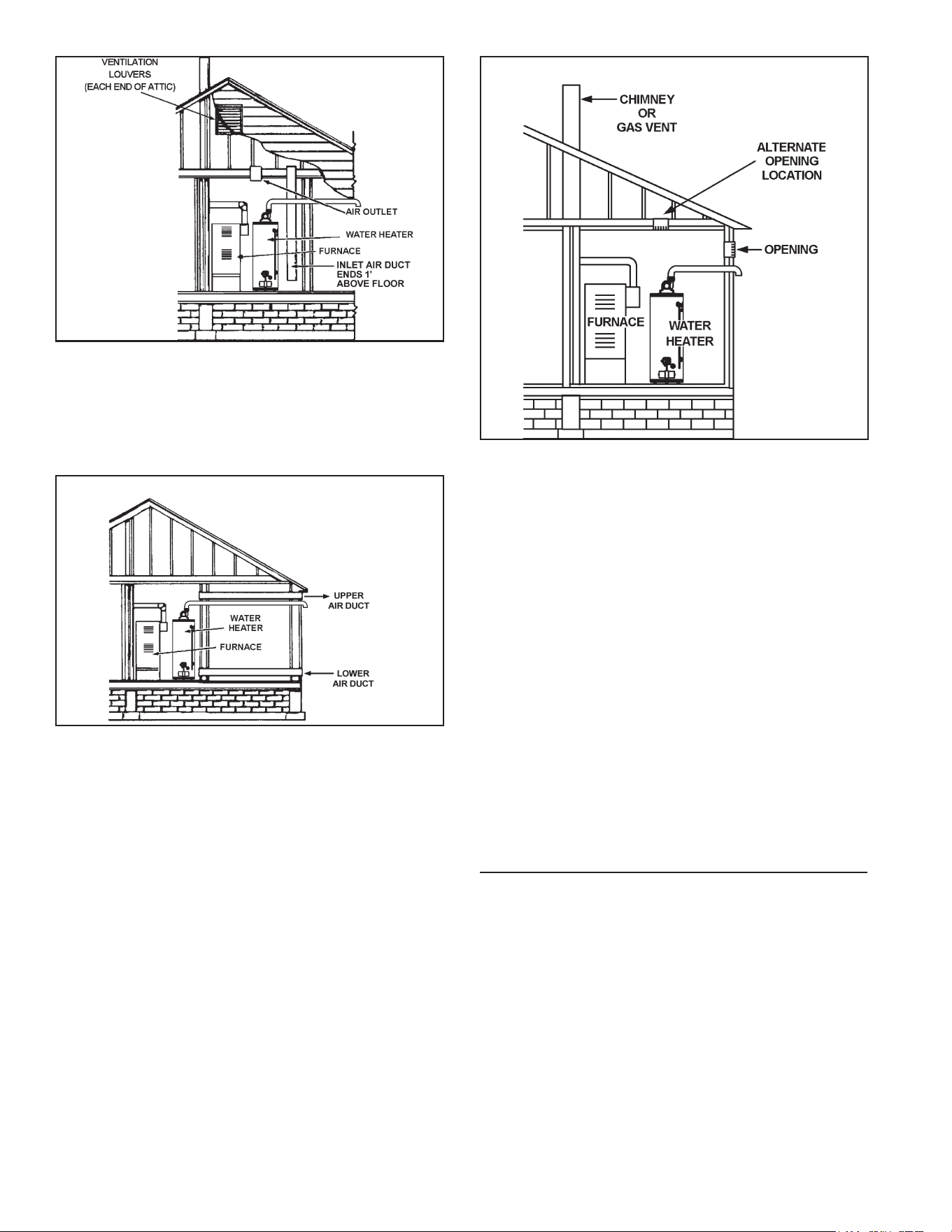
Figure 18.
4. When ducts are used, they shall be of the same
cross-sectionalareaasthefreeareaoftheopenings
to which they connect. The minimum short side
dimensionofrectangularairductsshallnotbeless
than3”(seeFigure19).
Figure 19.
5. Alternatively a single permanent opening may
be used when communicating directly with the
outdoors,orwithspacesthatfreelycommunicate
with the outdoors. The opening shall have a
minimumfreeareaof1squareinchper3,000Btu/
hroftotalinputratingofallequipmentinenclosure
(seeFigure20).
Figure 20.
6. Louvers and Grilles: In calculating free area,
considerationshallbegiventotheblockingeect
oflouvers,grillesorscreensprotectingopenings.
Screensusedshallnotbesmallerthan1/4”mesh.
Ifthefreeareathroughadesignoflouverorgrille
isknown,itshouldbeusedincalculatingthesize
openingrequiredtoprovidethefreeareaspecied.
Ifthedesignandfreeareaisnotknown,itmaybe
assumedthatwoodlouverswillbe20-25percent
free area and metal louvers and grilles will have
60-75percentfreearea.Louversandgrillesshall
bexedintheopenpositionorinterlockedwiththe
equipmentso thattheyare openedautomatically
duringequipmentoperation.
7. Special Conditions Created by Mechanical
ExhaustingorFireplaces:operationofexhaustfans,
ventilationsystems,clothesdryersorreplacesmay
createconditionsrequiringspecialattentiontoavoid
unsatisfactoryoperationofinstalledgasutilization
equipment.
CHEMICAL VAPOR CORROSION
CORROSION OF THE FLUEWAYS AND VENT SYSTEM
MAY OCCUR IF AIR FOR COMBUSTION CONTAINS
CERTAIN CHEMICAL VAPORS. SUCH CORROSION
MAYRESULTINFAILUREANDRISKOFASPHYXIATION.
Spraycanpropellants,cleaningsolvents,refrigeratorand
air conditioning refrigerants, swimming pool chemicals,
calciumandsodiumchloride(watersoftenersalt),waxes,
and process chemicals are typical compounds which
are potentially corrosive. Do not store products of this
sortneartheheater.Alsoairwhichisbroughtincontact
withtheheatershouldnotcontainanyofthechemicals.
If necessary, uncontaminated air should be obtained
fromremoteoroutsidesources.TheLimitedWarrantyis
voidedwhenfailureofwaterheaterisduetoacorrosive
atmosphere.See“LimitedWarranty”forcompleteterms
andconditions.
19
WATER PIPING
To reduce the risk of unusually hot water reaching
the xtures in the house, install Thermostatic Mixing
Valves at each point-of-use.
Water temperature over
125°F can cause severe
burns instantly resulting in
severe injury or death.
Children, the elderly and the
disabled and are at highest
risk of scald injury.
Feel water before bathing or
showering.
Temperature limiting devices
such as mixing must be
installed when required by
codes and to ensure safe
temperatures at fixtures.
BURN
HOT
HOT
DANGER
Thewatersupplypressureshouldnotexceed80psi.Ifthis
occurs,apressurereducingvalvewithabypassshouldbe
installedinthecoldwaterinletline.Thisshouldbeplaced
onthesupplytotheentirehouseinordertomaintainequal
hotandcoldwaterpressures.
HOTWATERCANSCALD:
Water heaters are intended to produce hot water.
Waterheatedtoatemperaturewhichwillsatisfyspace
heating, clothes washing, dish washing, cleaning and
othersanitizingneedscanscaldandpermanentlyinjure
you upon contact. Some people are more likely to be
permanently injured by hot water than others. These
include the elderly, children, the inrm, or physically/
mentally handicapped. If anyone using hot water ts
into one of these groups or if there is a local code or
statelawrequiringcertaintemperaturewateratthehot-
water tap, then you must take special precautions. In
additiontousinglowestpossibletemperaturesettingthat
satises that satses demand of application, to reduce
the risk of scalding, install Thermostatic Mixing Valves
(temperaturelimitingvalves)ateachpoint-of-use.These
valvesautomaticallymixhotandcoldwater to limitthe
temperatureatthetap.
SPACE HEATING AND POTABLE WATER SYSTEMS
This appliance has been design certied as complying
withAmericanNationalStandard/CSAStandardforwater
heatersandareconsideredsuitableforWater(Potable)
HeatingandSpaceHeating.Note:Waterheatersused
incombinationwater/spaceheatingshallnotbeusedin
spaceheatingonlyapplications.
Toxic Chemical Hazard
WARNING
• Do not connect to non-potable water system.
Consult a Qualied Installer or ServiceAgency. Follow
manufacturer’s instructions for installation of valves.
Beforechangingthefactorysettingonthermostat,read
“OperatingTheTemperatureControlSystem”sectionin
thismanual.
• This water heater should not be connected to any
heatingsystemsorcomponentspreviouslyusedwith
anon-potablewaterheatingappliance.
• Allpipingcomponentsconnectedtothisunitforspace
heating applications should be suitable for use with
potablewater.
• Toxicchemicals,suchasthoseusedforboilertreatment
shallnotbeintroducedintothepotablewaterusedfor
spaceheating.
• Ifthespaceheatingsystemrequireswatertemperatures
inexcessof120°F,installaThermostaticMixingValve
in the domestic (potable) hot water supply at each
point-of-usetolimittheriskofscaldinjury.
Note: Water piping and vent piping occupy the space
abovethewaterheater.Planthewaterpipingtoensure
itdoesnotcauseinterferencewiththeventpiping(see
“PlanningtheVentSystem”).
If this water heater is to be used to supply both space
heatingandpotablewater, theinstructionslistedbelow
mustbefollowed:
• Besuretofollowthemanual(s)shipped with the air
handlerorothertypeheatingsystem.
• Thiswaterheaterisnottobeusedasareplacement
foranexistingboilerinstallation.
• Do not use with piping that has been treated with
chromates,boilersealorotherchemicalsanddonot
addanychemicalstothewaterheaterpiping.
• Ifthespaceheatingsystemrequireswatertemperatures
inexcessof120°F,amixingvalvemustbeinstalled,
perthemanufacturer’sinstructions,inthepotablehot-
watersupplytolimittheriskofscaldinjury.
• Pumps,valves,pipingandttingsmustbecompatible
withpotablewater.
• A properly installed ow control valve is required to
prevent thermosiphoning. Thermosiphoning is the
result of a continuous ow of water through the air
handlercircuitduringtheocycle.Weeping(blowo)
ofthetemperature-pressurereliefvalve(T&P)orhigher
thannormalwatertemperaturesaretherstsignsof
thermosiphoning.
• The hot-water line from the water heater should be
vertical past any mixing valve or supply line to the
heatingsystemtoremoveairbubblesfromthesystem.
INSTALLING THE NEW WATER HEATER
20
• Do not connect the water heater to any system or
componentspreviously usedwith non-potablewater
heatingapplianceswhenusedtosupplypotablewater.
COMBO HEATING
Thissectionservesasaguidefortheinstallationanduse
of “Combo” heating systems utilizing a domestic water
heaterthathasbeenspecicallyapprovedforsuchuse.
Itiswrittenforthoseknowledgeableintherequiredtrades
andprofessionalsinvolvedinthedesignandinstallation
ofComboHeatingSystems.
Itistheresponsibilityoftheinstaller/designertofollowall
applicablecodestoensuretheeectivenessandsafety
oftheinstallation.
System Requirements
Thefollowingrequirementsmustbemetfortheinstallation
ofComboHeatingSystems:
1. Allcomponentsusedforthedistributionofwaterin
theheatingloopmustbesuitableforpotablewater.
These include all piping, ttings,solder and uxes,
pumpsforcirculationofwater,valves,etc.
2. Thewaterheatermustnotbeconnectedtoahydronic
heatingsystemthathasbeenusedpreviously.
3. No boiler treatment chemicals of any kind shall be
introducedintothesystem.
4. The Combo System components must be selected
andsizedtomeetandmaintainthetotalcalculated
demands for both domestic service hot water
and space heating requirement. The sizing and
installation must be performed in accordance with
good engineering practice such as “ASHRAE
Handbooks”, HRAI’s Unied Combo Guidelines,
“Hydronics Institute Manuals”, ANSI Z223.1, CSA
F280, National/Provincial Building Codes, ANSI
and/orcodeshavingjurisdiction.
5. Theairhandler(fancoil)and/orthecirculatingpump
inabaseboardhydronicloopwillrequireadedicated
120Vcircuit.Thismustbeprovidedandidentiedfor
thispurpose.
6. Allpipingbetweenthewaterheaterandtheairhandler
or hydronic baseboard loop must be adequately
insulatedtoreduceheatloss.
7. Ifthelocaljurisdictionrequiresaback-owpreventer
inthecoldwaterline,anexpansiontankofadequate
sizemustbeinstalled.
8. “Combo” Heating Systems require higher water
temperatures than other applications. When the
systemisused to supplywaterfor Combo Heating
applications,ameans,suchasmixingvalve,mustbe
installedtotemperthewaterinordertoreducescald
hazardpotential(seeFigure21&Figure22).
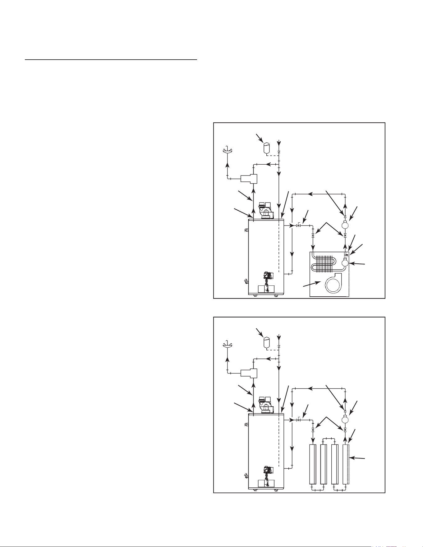
Installation
Theheatingmodemaybeoneofthefollowingoptions:
A. Afancoil/airhandler(Figure21).
B. Ahydronicbaseboard(nnedtube)loop/Inoorheating
(Figure22).
Thefollowingisalistofrequirementsfortheinstallation
ofoptionAorB.
1. Install shut-o valves and unions so that the water
heatercanbeisolatedfromtheheatingmoduleshould
servicing of the water heater become necessary.
2. Installadrainvalveatthelowestpointoftheheating
loopsothatwatercanbedrainedfromtheheating
modulewithoutaectingthewaterheater.
3. Iftheairhandlerdoesnothaveaventingmeansat
the highest point of the piping arrangement, install
an air bleed at the highest point of the plumbing
arrangement.
WATER
HEATER
8 in TO
12 in MAX.
HOT
OUTLET
EXPANSION TANK
(OPTIONAL)
MIXING
VALVE
COLD INLET
CHECK VALVE (IF USED
REQUIRES EXPANSION TANK)
COLD SUPPLY
HOSE BIB
(OPTIONAL)
FLOW
CONTROL
SUPPLY
RETURN
CHECK
VALVE
EXTERNAL
CIRCULATOR
AIR
HANDLER
HOT WATER
TO HOUSE
FIXTURE
C
H
M
INTERNAL
CIRCULATOR
DRAIN/
PURGE
VALVE
(seealso
Massachusetts
coderequirements
onpg8)
Figure 21.
(seealso
Massachusetts
coderequirements
onpg8)
WATER
HEATER
8 in TO
12 in MAX.
HOT
OUTLET
EXPANSION TANK
(OPTIONAL)
MIXING
VALVE
COLD INLET
CHECK VALVE (IF USED
REQUIRES EXPANSION TANK)
COLD SUPPLY
HOSE BIB
(OPTIONAL)
FLOW
CONTROL
SUPPLY
RETURN
CHECK
VALVE
EXTERNAL
CIRCULATOR
HOT WATER
TO HOUSE
FIXTURE
C
H
M
HYDRONIC
BASEBOARDS
(SERIES
CONNECTED
SHOWN)
Figure 22.
21
CLOSED WATER SYSTEMS
Watersupplysystemsmay,becauseofcoderequirements
orsuchconditionsashighlinepressure,amongothers,
haveinstalleddevicessuchaspressure-reducingvalves,
check valves, and back ow preventers. Devices such
asthesecausethewatersystemtobeaclosedsystem.
THERMAL EXPANSION
Aswaterisheated,itexpands(thermalexpansion).Ina
closedsystem,thevolumeofwaterwillincrease.Asthe
volumeofwaterincreases,therewillbeacorresponding
increase in water pressure due to thermal expansion.
Thermal expansion can cause premature tank failure
(leakage).This type of failureis notcovered under the
limited warranty. Thermal expansion can also cause
intermittenttemperature-pressurereliefvalveoperation:
waterdischargedfromthevalveduetoexcessivepressure
build up. The temperature-pressure relief valve is not
intendedfortheconstantreliefofthermalexpansion.This
conditionisnotcoveredunderthelimitedwarranty.
A properly-sized thermal expansion tank should be
installed on all closed systems to control the harmful
eectsofthermalexpansion.Contactaplumbingservice
agencyoryourretailsupplierregardingtheinstallationof
athermalexpansiontank.
Note:Toprotectagainstuntimelycorrosionofhotandcold
waterttings,itisrecommendedthatdi-electricunionsor
couplingsbeinstalledonthiswaterheaterwhenconnected
tocopperpipe.
• Avoid water heater damage.
• Install thermal expansion tank if necessary.
• Do not apply heat to cold water inlet.
• Contact qualified installer or service agency.
Property Damage Hazard
CAUTION
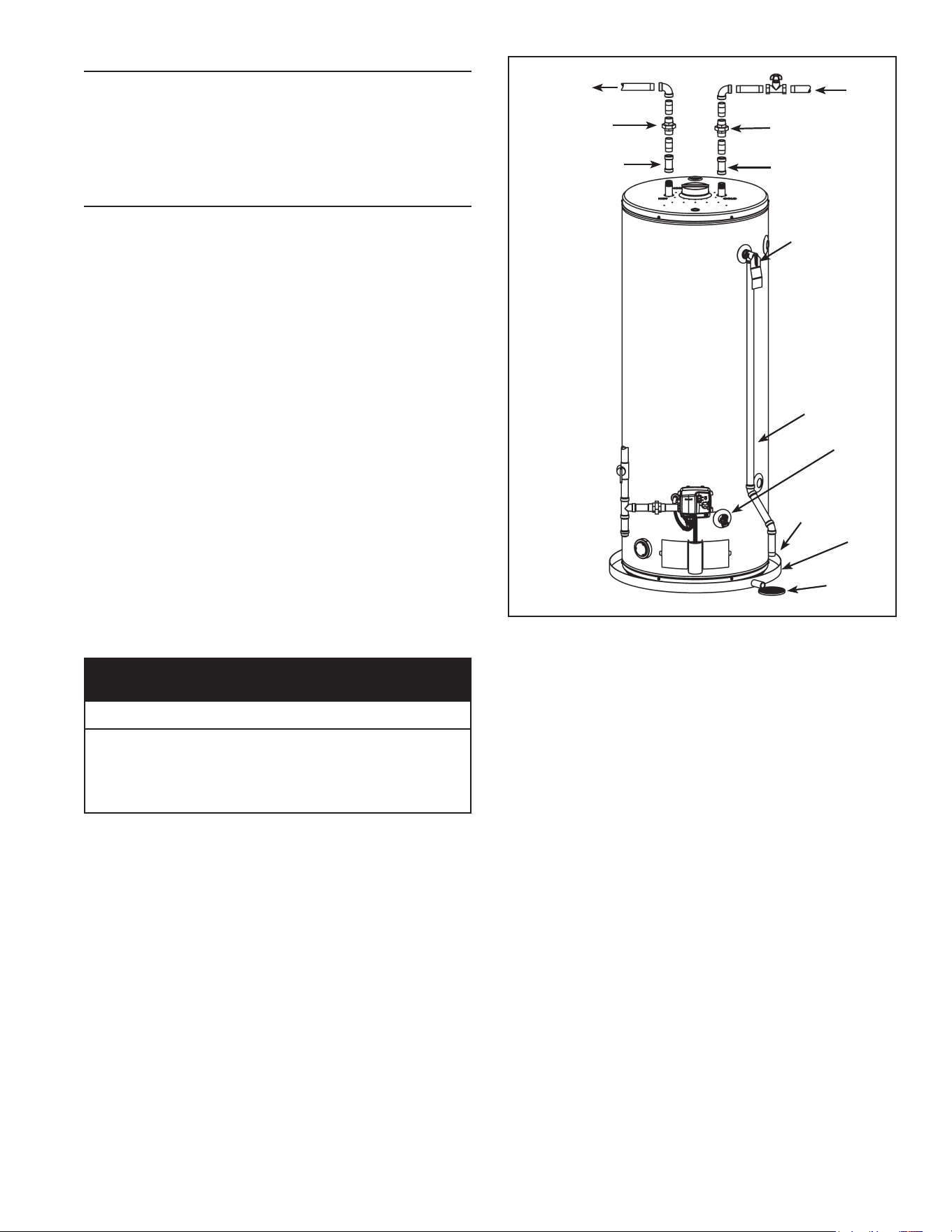
METAL
DRAIN
PAN
FLOOR
DRAIN
HOT-WATER
OUTLET
COLD-
WATER
INLET
UNION
UNION
3/4”SWEAT
FITTING
3/4”SWEAT
FITTING
TEMPERATURE-
PRESSURE
RELIEF VALVE
DISCHARGE PIPE
(DO NOT CAP
ORPLUG)
6”MAX.
AIR GAP
DRAIN
VALVE
SHUT-OFFVALVE
SOME
COMPONENTS
NOT SHOWN
FOR CLARITY.
Figure 23.
Figure21showstypicalattachmentofwaterpipingtothe
waterheater.Thewaterheaterisequippedwith3/4”NPT
waterconnections.
Note: If using copper tubing, solder tubing to an
adapterbeforeattachingtheadaptertothewaterheater
connections.Donotsolderthewaterlinesdirectlytothe
waterheaterconnections-itwillharmthediptubeand
heattrapsanddamagethetank.
22
TEMPERATURE-PRESSURE RELIEF VALVE
• Temperature-pressure relief
valve must comply with ANSI
Z21.22-CSA4.4 and ASME
code.
• Properly sized temperature-
pressure relief valve must be
installed in opening provided.
• Do not plug, block, or cap the
discharge line.
• Failure to follow this warning
can result in excessive tank
pressure, serious injury or
death.
Explosion Hazard
WARNING
Thiswaterheaterisprovidedwithaproperlyrated/sized
and certied combination Temperature-Pressure Relief
Valve (T&P valve) by the manufacturer. The valve is
certied by a nationally recognized testing laboratory
thatmaintainsperiodicinspectionofproductionoflisted
equipmentofmaterialsasmeetingtherequirementsfor
Relief Valves for Hot Water Supply Systems, ANSI
Z21.22-CSA 4.4,andthecoderequirementsofASME.
Ifreplaced,thenewT&Pvalvemustmeettherequirements
oflocalcodes,butnotlessthanacombinationtemperature-
pressurereliefvalverated/sizedandcertiedasindicated
intheaboveparagraph.Thenewvalvemustbemarked
withamaximumsetpressurenottoexceedthemarked
hydrostaticworkingpressureofthewaterheater(150psi)
andadischargecapacitynotlessthanthewaterheater
Btu/hrinputrateasshownonthewaterheater’smodel
ratingplate.
Forsafeoperationofthewaterheater,thetemperature-
pressure relief valve must not be removed from its
designatedopeningnorplugged.TheT&Pvalvemustbe
installeddirectlyintothettingofthewaterheaterdesigned
for the relief valve. Install discharge piping so that any
dischargewillexitthepipewithin6”aboveanadequate
oordrain,orexternaltothebuilding.Incoldclimatesitis
recommendedthatitbeterminatedatanadequatedrain
insidethebuilding.Becertainthatnocontactismadewith
anyliveelectricalpart.
Thedischargeopeningmustnotbeblockedorreducedin
sizeunderanycircumstances.Excessivelength(over30
feet),oruseofmorethanfourelbowscancauserestriction
andreducethedischargecapacityofthevalve.
Novalveorotherobstructionistobeplacedbetweenthe
T&Pvalveandthetank.Donotconnectdischargepiping
directlyto thedrain unlessa maximum of 6” air gap is
provided.Topreventbodilyinjury,hazardtolife,orproperty
damage, the relief valve must be allowed to discharge
water in adequate quantities should circumstances
demand.Ifthedischargepipeisnotconnectedtoadrain
orothersuitablemeans,thewaterowmaycauseproperty
damage.
• Temperature-pressure relief valve discharge pipe
must terminate at an adequate drain.
Water Damage Hazard
CAUTION
T&P valve discharge pipe requirements:
• Shallnotbesmallerinsizethantheoutletpipesize
ofthevalve,orhaveanyreducingcouplingsorother
restrictions.
• Shallnotbepluggedorblocked.
• Shallnotbeexposedtofreezingtemperatures.
• Shallbeofmateriallistedforhotwaterdistribution.
• Shall be installed so as to allow complete drainage
ofboththetemperature-pressurereliefvalveandthe
dischargepipe.
• Mustterminateamaximumofsixinchesaboveaoor
drainorexternaltothebuilding.Incoldclimates,itis
recommendedthatthedischargepipebeterminated
atanadequatedraininsidethebuilding
• Shallnothaveanyvalveorotherobstructionbetween
thereliefvalveandthedrain.
• Burn hazard.
• Hot water discharge.
• Keep clear of
temperature-pressure
relief valve discharge.
BURN
HOT
HOT
DANGER
TheT&Pvalvemustbemanuallyoperatedatleastonce
ayear.Cautionshouldbetakentoensure(1)nooneis
infrontoforaroundtheoutletofthedischargeline,and
(2) the water manually discharged will not cause any
bodilyinjuryorpropertydamagebecausethewatermay
beextremelyhot.Ifaftermanuallyoperatingthevalve,it
failstocompletelyresetandcontinuestoreleasewater,
immediatelyclosethecold-waterinlettothewaterheater,
followthedraininginstructionsinthismanual,andreplace
thetemperature-pressurereliefvalvewithaproperlyrated/
sizednewone.
23
Note:Thepurposeofatemperature-pressurereliefvalve
is to prevent excessive temperatures and pressures in
thestoragetank.TheT&Pvalveisnotintendedforthe
constant relief of thermal expansion.A properly sized
thermal expansion tank must be installedon all closed
systemstocontrolthermalexpansion,see“ClosedWater
Systems”and“ThermalExpansion”section.
Temperature-Pressure Relief Valve and Pipe
Insulation
TheT&Pvalveinstalledonthiswaterheateriscoveredby
insulationtominimizeheatloss.Theinsulationhasahole
onthebottomsidetoaccommodatethevalveoutletand
allowforthepipingconnection.Donotrestricttheoutlet
openingoftheT&Pvalve.
T&P Relief Valve
T&P Relief Valve
Drain Line
Manual Relief Lever
T&P Relief Valve Insulation
(Outlet opening on underside)
Figure 24.
Locatethetemperatureandpressurereliefvalveonthe
water heater (also known as a T&P relief valve). See
Figure24.
1. Locate the slit running the length of the T&P relief
valveinsulation.
2. SpreadtheslitopenandttheinsulationovertheT&P
reliefvalve.SeeFigure24.Applygentlepressureto
theinsulationtoensurethatitisfullyseatedontheT&P
ReliefValve.Onceseated,securetheinsulationwith
ducttape,electricaltape,orequivalent.IMPORTANT:
Theinsulationandtapemustnotblockthedischarge
openingorhinderaccesstothemanualrelieflever
(Figure24).Ensureadischargepipeisinstalledinto
theT&Pvalvedischargeopeningpertheinstructions
inthismanual.
3. Locatethehotwater(outlet)&coldwater(inlet)pipes
tothewaterheater.
4. Locatetheslitrunningthelengthofasectionofpipe
insulation.
5. Spreadtheslitopenandsliptheinsulationoverthe
coldwater(inlet)pipe.Applygentlepressure along
the lengthof the insulation to ensure that it is fully
seatedaroundthepipe.Also,ensurethatthebase
oftheinsulationisushwiththewaterheater.Once
seated,securetheinsulationwithducttape,electrical
tape,orequivalent.
6. Repeatsteps5and6forthehotwater(outlet)pipe.
7. Addadditionalsectionsofpipeinsulationasneeded.
HIGH ALTITUDE INSTALLATION
Breathing carbon monoxide can cause brain damage or death.
Always read and understand instruction manual.
• For operation above 10,100 ft.
(3,079 metres) a high altitude
orifice must be installed.
• Contact a qualified installer or
service agency.
Breathing Hazard - Carbon Monoxide Gas
WARNING
Thisheaterisapprovedforoperationupto10,100feet
withoutalteration.
Failure to replace standard orice with a high altitude
orice when installed above 10,100 feet could result
in improper and inecient operation of the appliance,
producingcarbonmonoxidegasinexcessofsafelimits,
which could result in serious injury or death. Contact
yourgassupplierforanyspecicchangeswhichmaybe
requiredinyourarea.
GAS PIPING
• Do not use water heater with
any gas other than the gas
shown on the rating plate.
• Excessive pressure to gas
control valve can cause serious
injury or death.
• Turn off gas lines during
installation.
• Contact qualified installer or
service agency.
Fire and Explosion Hazard
WARNING
Explosion Hazard
Have a qualified technician make sure that the L.P.
gas operating pressure does not exceed 13" water
column.
Failure to do so can result in death, explosion, or
fire.
WARNING
24
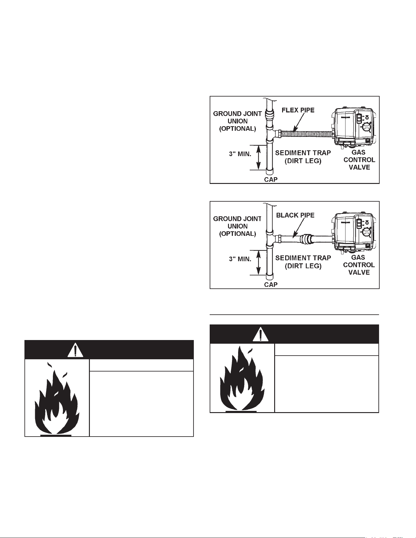
Makesure thegas supplied is the same type listed on
themodelratingplate.Theinletgaspressuremustnot
exceed14inchw.c.fornaturalgasandpropanegas.The
minimuminletgaspressureshownontheratingplateis
thatwhichwillpermitringatratedinput.
Allgaspipingmustcomplywithlocalcodesandordinances
orwiththeNational Fuel Gas Code (ANSI Z223.1/ NFPA-
54).Copperorbrasstubingandttings(excepttinlined
coppertubing)shouldnotbeused.
If the gas control valve/thermostat is subjected to
pressures exceeding 1/2 psi, the damage to the gas
controlvalve/thermostatcouldresultinareorexplosion
fromleakinggas.
Ifthemaingaslineshut-oservingallgasappliancesis
used,alsoturn“OFF”thegasateachappliance.Leave
all gas appliances shut “OFF” until the water heater
installationiscomplete.
Agaslineofsucientsizemustberuntothewaterheater.
ConsultthecurrenteditionofNational Fuel Gas Code
(ANSI Z223.1/NFPA 54)andyourgassupplierconcerning
pipesize.
Theremustbe:
• Areadilyaccessiblemanualshut-ovalveinthegas
supplylineservingthewaterheater,and
• Asedimenttrap(dirtleg)aheadofgascontrolvalve/
thermostattohelppreventdirtandforeignmaterials
fromenteringthegascontrolvalve/thermostat.
• Aexiblegasconnectororagroundjointunionbetween
theshut-ovalveandgascontrolvalve/thermostatto
permitservicingoftheunit.
Besuretocheckallthegaspipingforleaksbeforelighting
thewaterheater.Useasoapywatersolution,notamatch
or open ame. Repair and retest as required. When
nished,rinseosoapysolutionandwipedry.
• Use joint compound or tape
compatible with propane.
• Leak test before operating
heater.
• Disconnect gas piping and
shut-off valve before pressure
testing system.
Fire and Explosion Hazard
WARNING
UsepipejointcompoundorTeontapemarkedasbeing
resistanttotheactionofgases.
Theapplianceanditsgasconnectionmustbeleaktested
beforeplacingtheapplianceinoperation.
Theapplianceanditsindividualshut-ovalveshouldbe
disconnectedfromthegassupplypipingsystemduring
anypressuretestingofthatsystemattestpressuresin
excessof1/2psi.Itshouldbeisolatedfromthegassupply
piping system by closing its individual manual shut-o
valveduringanypressuretestingofthegassupplypiping
systemattestpressuresequaltoorlessthan1/2psi.
Connectinggaspipingtothegascontrolvalve/thermostat
of water heater can be accomplished by either of two
methodsshowninFigure25&Figure26.
Figure 25.
Figure 26.
SEDIMENT TRAPS/DIRT LEG
• Contaminants in gas lines can
cause fire or explosion.
• Clean all gas piping before
installation.
• Install sediment trap in accor-
dance with NFPA54.
Fire and Explosion Hazard
WARNING
Asedimenttrapshouldbeinstalledasclosetotheinletof
thewaterheateraspracticalatthetimeofwaterheater
installation.Thesedimenttrapshouldbeeitherateetting
withacappednippleinthebottomoutletorotherdevice
recognizedasaneectivesedimenttrap.Ifateettingis
used,itshouldbeinstalledinconformancewithoneofthe
methodsofinstallationshowninFigure25&Figure26.
Contaminants in the gas lines may cause improper
operation of the gas control valve/thermostat that may
resultinreorexplosion.Beforeattachingthegaslinebe
surethatallgaspipeiscleanontheinside.Totrapany
dirtorforeignmaterialinthegassupplyline,asediment
25
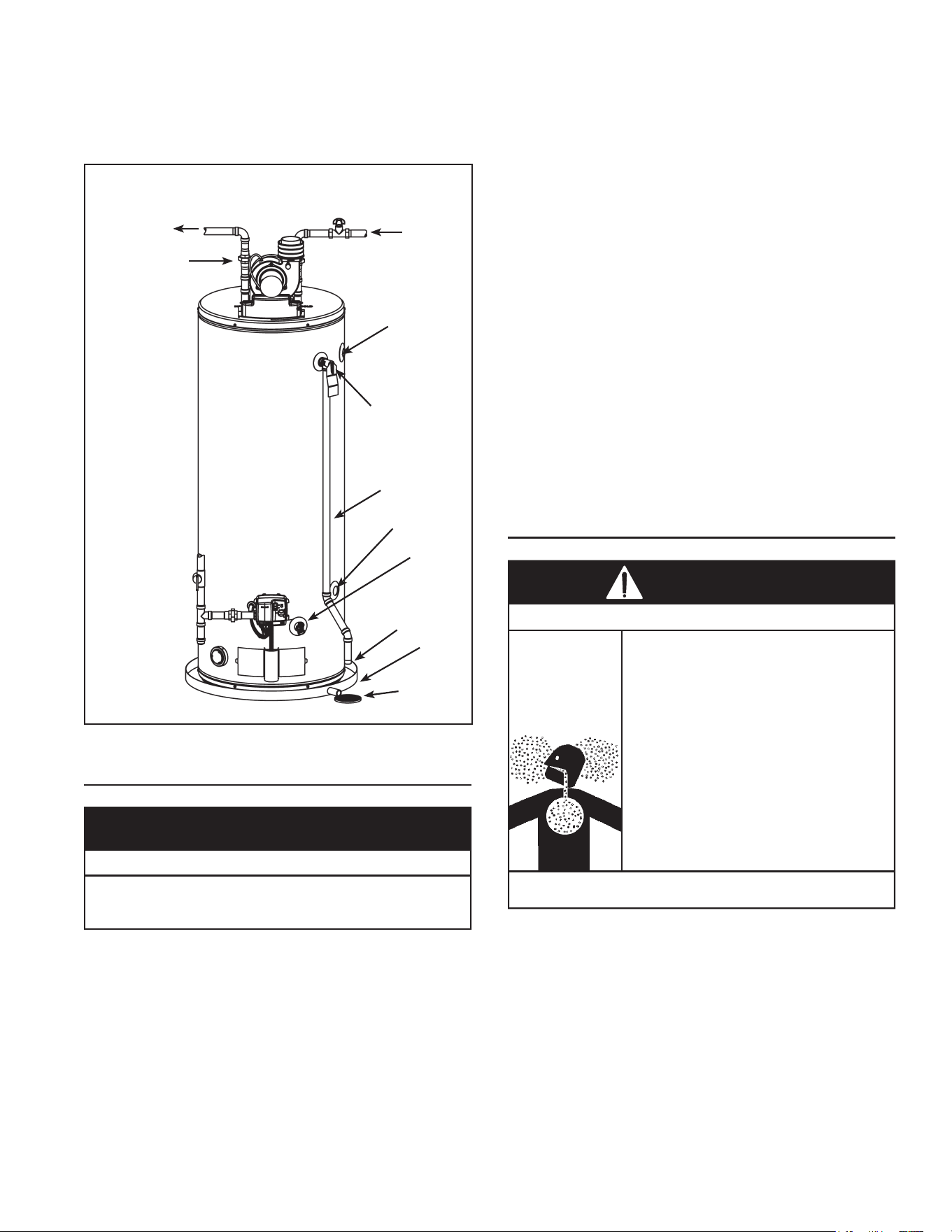
trap(sometimescalledadirtleg)mustbeincorporatedin
thepiping.Thesedimenttrapmustbereadilyaccessible.
Installinaccordancewiththe“GasPiping”section.Referto
thecurrenteditionoftheNational Fuel Gas Code (ANSI
Z223.1/NFPA 5 4).
HOT-WATER
OUTLET
COLD-
WATER
INLET
UNION
TEMPERATURE-
PRESSURE
RELIEF VALVE
DISCHARGE PIPE
(DO NOT CAP
ORPLUG)
6”MAX.AIRGAP
BELOW DISCHARGE
PIPE
METAL
DRAIN
PAN
FLOOR
DRAIN
DRAIN
VALVE
SHUT-OFFVALVE
SOME
COMPONENTS
NOT SHOWN
FOR CLARITY.
SIDE TAP
(OUTLET)
SIDE TAP
(INLET)
Figure 27.
FILLING THE WATER HEATER
• Avoid water heater damage.
• Fill tank with water before operating.
Property Damage Hazard
CAUTION
• Do not insert the power cord into the electrical
receptacleuntiltheheaterhasbeenfullyinstalled.
• Neverusethiswaterheaterunlessitiscompletelyfull
ofwater.Topreventdamagetothetank,thetankmust
belledwithwater.Watermustowfromthehot-water
faucetbeforeturning“ON”gastothewaterheater.
Tollthewaterheaterwithwater:
1. Closethewaterheaterdrainvalvebyturninghandle
totheright(clockwise).Thedrainvalveisonthelower
frontofwaterheater(seeFigure27).
2. Iftheheaterisequippedwithplumbingsidetapsand
theyarenotconnectedtopiping,ensurethattheside
tapshavebeenclosedwithpipeplugs.
3. Openallhot-waterfaucetsservedbythewaterheater
to allow air to escape from the tank and the water
piping.Ensureanyshut-ovalvesbetweentheheater
andthefaucetsaretheopenposition.
4. Openthecold-watersupplyvalvetothewaterheater.
Notes:
• Thecold-watersupplyvalvemustbeleftopenwhen
thewaterheaterisinuse.
• Avoidwaterleakagewhenllingthetank.Donot
allowtheinsulationofthewaterheatertogetwetas
watercanreducetheeectivenessoftheinsulation.
5. Toensurecompletellingofthetank,allowairtoexit
byopeningnearesthot-waterfaucet.Allowwaterto
rununtilaconstantowisobtained.Thiswillletair
outofthewaterheaterandthepiping.
6. Check all water piping and connections for leaks.
Repairasneeded.
VENTING
Breathing carbon monoxide can cause brain damage or death.
Always read and understand instruction manual.
• Install vent system In accordance with codes.
• Do not operate water heater if flood damaged.
• Install water heater in accordance with the
instruction manual.
• Do not operate if soot buildup is present.
• Do not obstruct water heater air intake(s) with
insulating blanket.
• Do not place chemical vapor emitting products near
water heater.
• Gas and carbon monoxide detectors are available.
• Never operate the heater unless it is vented to the
outdoors and has adequate air supply to avoid risks
of improper operation, fire, explosion or asphyxia-
tion.
• Analyze the entire vent system to make sure that
condensate will not become trapped in a section of
vent pipe and therefore reduce the open cross
sectional area of the vent.
Breathing Hazard - Carbon Monoxide Gas
WARNING
Important:DONOTcommonventthiswaterheaterwith
anypowerventedappliance.DONOTventintoacommon
chimney.
26
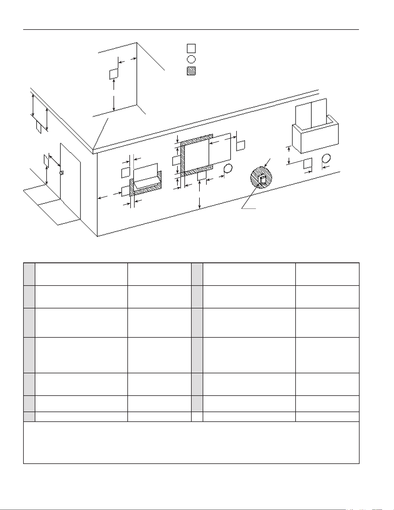
TERMINATION CLEARANCES SIDEWALL POWER VENT
INSIDE CORNER
DETAIL
FIXED
CLOSED
OPERABLE
FIXED
CLOSED
OPERABLE
Vent terminal
Air supply inlet
Area where is not permitted
Gas meter / regulator
C
B
B
B
B
B
J
A
K
M
F
B
L
E
D
I
V
V
V
V
V
V
V
V
V
V
X
X
X
G
A
Figure 28.
Ventterminalclearancesfor“PowerVent”installations.PowerVentcongurationsuseroomairforcombustion.
A
Clearanceabovegrade,
veranda,porch,deckor
balcony
12in. H
Clearancetoeachsideof
centerlineextendedabove
meter/regulatorassembly
N/A
B
Clearancetowindowordoor
thatmaybeopened
4ft.belowortoside
ofopening;1ft.
aboveopening
I
Clearancetoserviceregulator
ventoutlet
3ft.*
C
Clearancetopermanently
closedwindow
12in.* J
Clearancetoanon
mechanicalairsupplyinletinto
buildingorcombustionairinlet
toanyotherappliance
4ft.belowortoside
ofopening;1foot
aboveopening.
D
Verticalclearancetoventilated
sotlocatedabovethe
terminalwithinahorizontal
distanceof2ft.fromthe
centerlineoftheterminal
12in.* K
Clearancetoamechanicalair
supplyinlet
3ft.aboveifwithin
10ft.horizontally
E
Clearancetounventilated
sot
12in.* L
Clearanceabovepaved
sidewalkorpaveddriveway
locatedonpublicproperty
7ft.†
F Clearancetooutsidecorner 2ft.* M
Clearanceunderveranda,
porch,deck,orbalcony
12in.‡
G Clearancetoinsidecorner 18in.*
InaccordancewiththecurrentANSIZ223.1/NFPA54,NationalFuelGasCode.
†Aventshallnotterminatedirectlyaboveasidewalkorpaveddrivewaythatislocatedbetweentwosinglefamily
dwellingsandservesbothdwellings.
‡Permittedonlyifveranda,porch,deck,orbalconyisfullyopenonaminimumoftwosidesbeneaththeoor.
*Clearanceinaccordancewithlocalinstallationcodesandtherequirementsofthegassupplierandthe
manufacturer’sinstallationinstructions.
27
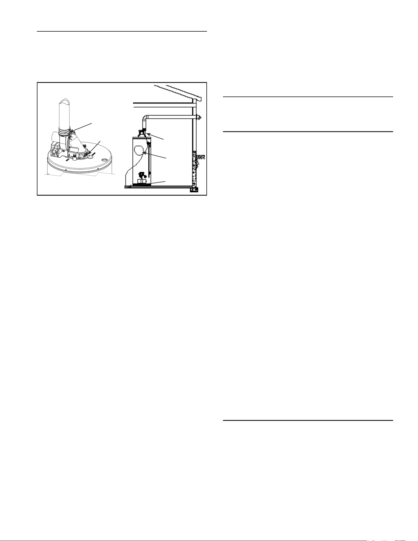
BLOWER ASSEMBLY INSTALLATION
1. Thispowerventedwaterheatercomeswithblower
assemblyinstalled(seeFigure29).
2. Afterunitissetinplace,makesureblowerassemblyis
stillmountedsecurely.Makesurethereisnodamage
toblower.
HOSE
CONNECTION
PORT FOR
CONDENSATE
DRAIN
DILUTION
AIR
INLETS
8in.
LOOP
TO
DRAIN
BLOWER
ASSEMBLY
Figure 29.
3. Makesurethereisnopackingmaterialintheinletor
dischargeoftheblower.
4. Make sure that the plastic tubing is still attached
fromtheairpressureswitchtotheportontheblower
housing. Make sure the plastic tubing is not folded
anywherebetweenthepressureswitchandtheblower
housing(seeFigure37thruFigure41).
5. Thiswaterheaterisapolaritysensitiveapplianceand
willnotoperateifthepowersupplypolarityisreversed.
Power to this water heater must be wired properly
(correctpolarity).
6. Do not plug in power cord until vent system is
completelyinstalled.ThePowerVentoperateson110
-120VAC.thereforeagroundedoutletmustbewithin
reachofthe6footexiblepowercordsuppliedwith
theheater.Thepowercordsuppliedmaybeusedon
aunitonlywherelocalcodespermit.Iflocalcodesdo
notpermituseofexiblepowersupplycord:
a. Make sure the unit is unplugged from the wall
outlet.Removethescrewandopenpanelonthe
frontofthejunctionboxontheblower.
b. Cuttheexiblepowercord,leavingenoughtobe
abletomakeconnections.Removethestrainrelief
ttingfromthebox.
c. Installasuitableconduitttinginsidetheenclosure.
d. Spliceeldwiringintoexistingwiringusingcode
authorizedmethod(wirenuts,etc).
e. Be certain that the neutral and line connections
arenotreversedwhenmakingtheseconnections.
f. Groundheaterproperly.Thiswaterheatermustbe
groundedinaccordancewiththeNationalElectrical
CodeNFPA70and/orlocalcodes.Thesemustbe
followed in all cases.The waterheater must be
connectedtoagroundedmetal,permanentwiring
systemoranequipmentgroundingconductormust
berunwiththecircuitconductorsandconnected
totheequipmentgroundingterminalorleadonthe
waterheater(seeFigure12;thewiringdiagram).
g. Closethe panel onthe junction box. Make sure
thattheaccesspanelissecuredshut.
7. The blower discharge boot is made to accept only
straightsectionsof2”or3”pipe.Tostartowithan
elbow,ashortsectionofthestraightpipemustbecut
andgluedintotheendoftheelbowthatwillmounton
thedischargeboot.
INSTALLATION OF VENT SYSTEM
Beforebeginninginstallationofpipingsystem,thoroughly
readthe“VentPipePreparation”sectionofthismanual.
PLANNING THE VENT SYSTEM
Planthelayoutoftheventsystemfromtheventtermination
tothewaterheaterconsideringallofthe90degreeand45
degreeelbowsplusthenumberoffeetofpipethatwould
beneededtoinstallthetotalventsystem.Thewaterheater
must be vented to the outdoors as described in these
instructions.Thiswaterheatermustbeventedseparately
fromallotherappliances.
The unit may be vented horizontally through a wall or
verticallythroughtheroof.Piperunsmustbeadequately
supportedalongbothverticalandhorizontalruns.
Note:Donotuseanelbowasasupportpoint.Elbowsare
notdesignedtocarrytheloadorstressesoftheventing
systemiftheyarerigidlyheld.
Itisimperativethatthersthanger(orsupport)belocated
on the horizontal run immediately adjacent to the rst
90-degreeelbowfromtheverticalrise.Supportmethod
usedshouldisolatetheventpipefromtheoorjoistsor
otherstructuralmemberstopreventthetransmissionof
noise and vibration. Do not support, pin, or otherwise
secure the venting system in a way that restricts the
normalthermalexpansionandcontractionofthechosen
ventingmaterial.
Ifthewaterheaterisbeinginstalledasareplacementfor
anexistingpowerventedheaterinpre-existingventing,
athoroughinspectionofexistingventingsystemmustbe
performedpriortoanyinstallationwork.Verifythatcorrect
material,asdetailedinbelow,hasbeenused,andthatthe
minimumormaximumventlengthsandterminallocation
asdetailedinthismanualhavebeenmet.
HIGH AMBIENT TEMPERATURE INSTALLATIONS
This heater requires room air to lower the flue gas
temperatures before the gases pass through the vent
system.Thedilutionairinletsarelocatedontherearof
theblowerassembly(seeFigure2&Figure29).
Astheroomtemperaturerises,theabilitytolowertheue
gaseslessenssospecialattentiontothechoiceofventing
materialisrequired.Establishingtheambienttemperatures
where the heater and the venting is installed is very
important, especially in regions with warmer climates
or any region that experiences hot summers.Ambient
conditions hotter than 110°F require that the venting
28
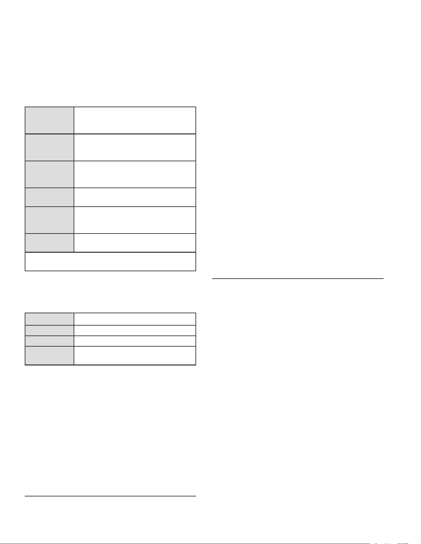
materialbeeitherCPVCorpolypropylene.Areasthatcan
experience high ambient environments include closets,
alcoves,areasunderstaircases,attics-especiallyinmetal
roofed buildings, areas with restricted air movement,
roomswithlargesolargains,metal sheds, industrialor
commercialenterprisesandventingsystemsexposedto
directsunlight.Forhightemperatureenvironments,obtain
highlimitswitchupgradeKit#9008306015andusethe
higherratedventpiping.
Note:Thisunitcanbeventedwiththefollowingpiping:
PVCpipe
materials
(solidpipe)
DWVASTM-D2665
Schedule40,80*&120*ASTM-D1785,
SDRSeriesASTM-D2241
PVCpipe
materials
(cellularcore)
ASTM-D4396
CPVCpipe
materials
CPVC41ASTM-D2846
Schedule40,80*&120*ASTM-F441
SDRSeriesASTM-F442,
ABSpipe
materials
DWVASTM-D2661
Schedule40
ABSpipe
materials
(cellularcore)
ASTMF-628
Polypropylene
ventsystem
UL-1738
* NOTE: USINGSCHEDULE80OR120
SIGNIFICANTLY REDUCES THE VENT LENGTH.
Note:Iflocalcodesrequireventingtobemarkedsuitable
foruseasgasventing,typeBHventingmaybeused.
The fittings, other than the Termination should be
equivalentto:
PVCpipe
PVCDWVASTMD-2665
CPVCpipe CPVCASTMF-438
ABSpipe ABSASTMD-2661/3311
Polypropylene
ventsystem
UL-1738
If CPVC orABS pipe and ttings are used, the proper
cementmustbeusedforalljoints,includingjoiningthe
pipetoTermination(PVCMaterial).Iflocalcodesdonot
allow the use of the PVC termination when a material
otherthanPVCisusedforventing,anequivalentttingof
thatmaterialmaybesubstitutedifthescreeninthePVC
terminalisremovedandinsertedintothenewtting.
This water heater is supplied with a 45 degree PVC
terminationelbowandtheapplicableventscreens.A90
degreeterminationelbowisoptional.
ASTM D-2564 Grade Cement should beused on PVC
Materials andASTM F-493 Grade Cement on CPVC
Materials.
POLYPROPYLENE VENT SYSTEMS
Polypropyleneventsystemsdonotusecementtoconnect
thepipeandelbowsectionsbutuseapushtogethergasket
seal method. Do not attempt to connect polypropylene
withsealantcement.
Polypropyleneventsystemsaredesignedtousespecic
adaptorstoconnectintotherubbercouplingonthetop
oftheblower.Theseareavailablethroughyourventing
supplier.
ThePVCventterminationelbowsuppliedwiththisheater
has been certied to be used with polypropylene vent
systems.A polypropylene to PVC end connection is
requiredandisavailablethroughyoursupplier.
Optionalwallplatesthattthepolypropyleneventingare
alsoavailablethroughyoursupplier.
Carefullyinspecttheentireventingsystemforanysignsof
cracksorfractures,particularlyatjointsbetweenelbows
andother ttings andstraight runs ofvent pipe. Check
systemforsignsofsaggingorotherstressesinjointsas
aresultofmisalignmentofanycomponentsinthesystem.
Ifanyoftheseconditionsarefound,theymustbecorrected
inaccordancewiththeventinginstructionsinthismanual
beforecompletinginstallationandputtingthewaterheater
intoservice.
The vent piping shall be connected to the blower with
therubbercouplingandsecuredwithgearclamps.The
couplingandclampsareprovidedwiththeheater.
Eventhoughtheuegastemperatureleavingtheblower
is hot, some installations will have water condense in
theventpiping.Ifthis occurs, thenadequatemeansof
draininganddisposingofthecondensateshallbemade
bytheinstaller.
CONDENSATE
Condensateformationdoesnotoccurinallinstallations
of power vented water heaters, but should be drained
oninstallationswhereitcanformintheventingsystem.
Condensation in the venting system of power vented
waterheatersisdependentuponinstallationconditions
including, but not limited to, ambient temperature and
humidity of installation location, ambient temperature
andhumidityofventingspace,ventdischargeandslope,
andproductusage.Incertainconditions,installationsin
unconditionedspaceorhavinglonghorizontalorvertical
ventrunscanaccumulatecondensate.Longlengthsof
ventingthatpassthroughcool/coldareaswillexperience
condensation.Theventpipeshouldbeslopedupwards
awayfrom theblowerassembly, thenadequate means
for draining and disposing of the condensate needs to
bemadebytheinstaller.Ifinstallationconditionscause
condensation,installacondensatetraploopapproximately
8in.indiameterusing3/8”plastichose.Connectthehose
tothebuilt-indrainportoftherubbercouplingoftheblower
assembly (see Figure 29). Loop the hose in a vertical
positionasshown.Thetubeloopmustbelledwithwater
atleasthalfwaypriortooperatingtheheater.Ensurethe
endofthetubehasaccesstoadrainascondensatewill
owfrom the end.Secure the tubingto thesideof the
heater. Prior to operating the water heater, make sure
theremovablecapisinstalledonthedrainport(ifadrain
hoseisnotneeded).
Note:Thiscapmustremaininplaceifadrainhoseisnot
installed.
29
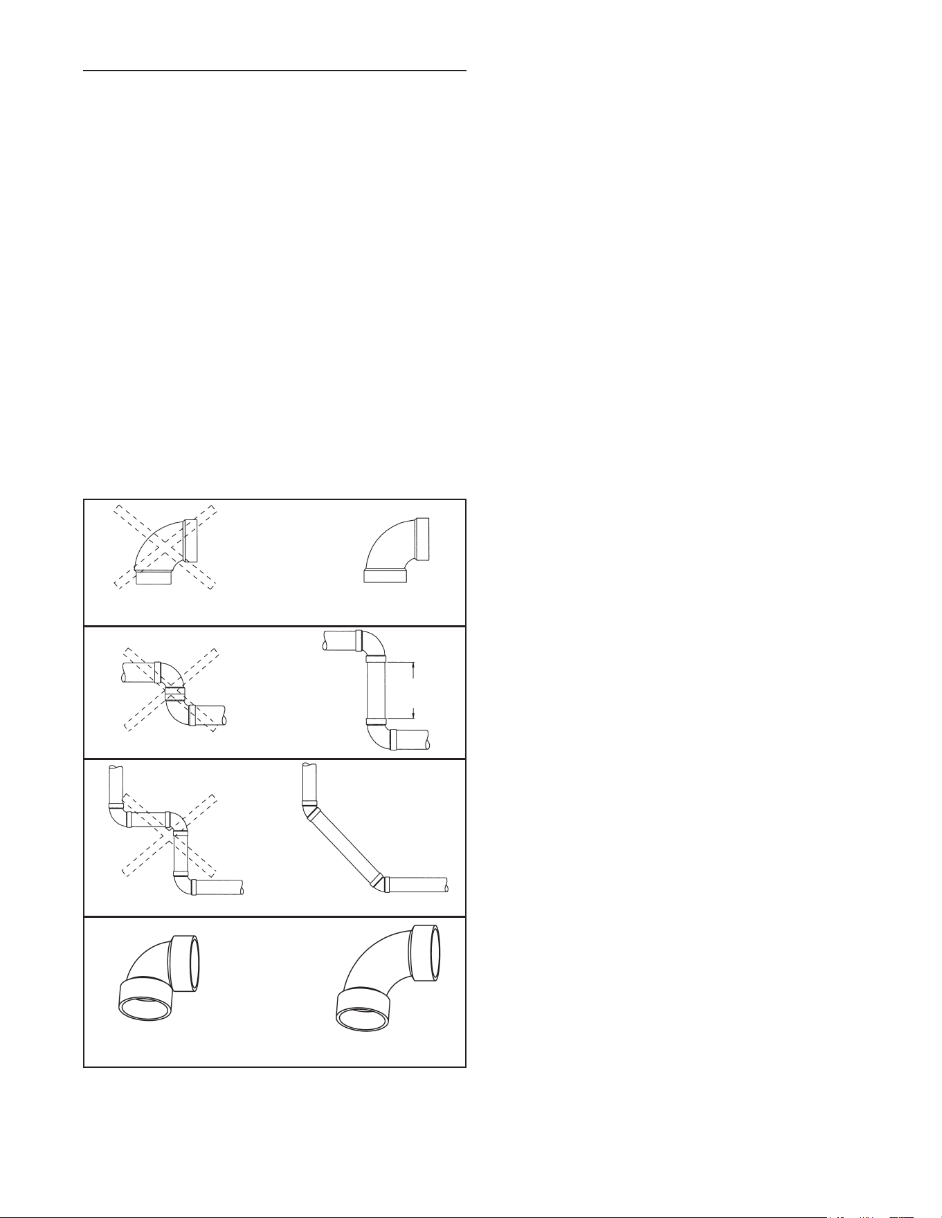
EXHAUST VENTING
This heater is designed to exhaust the products of
combustion(uegases)totheoutdoorsusingasealed
pipingsystem.Table2liststheallowableventmaterials
and sizing information. Figure 33 shows the general
ventinglayoutwhileFigure37thruFigure41showvarious
endterminationdetailsandclearances.Connectionofthe
ventingpipingtothe blower isshowninFigure37 thru
Figure41.
Correctinstallationoftheventingsystemisessentialto
thesafeandecientoperationofthiswaterheater.Vent
pipingmustbeinstalledinaccordancewithallapplicable
codes.All installations shall meet the requirements as
statedinthecurrenteditionofthe “National Fuel Gas
Code, ANSI Z223.1/NFPA 54”.
Note:TheinformationprovidedinFigure28isintended
as a guideline for good vent installation practices only
and is not intended to restrict venting options beyond
thoserestrictionsestablishedbythecurrenteditionofthe
“National Fuel Gas Code, ANSI Z223.1/NFPA 54”orany
applicablelocalandstatecodes.
6in.
min.
BACKTOBACKELBOWS
NORMAL ELBOW
90°LONGSWEEPELBOW
(LESSRESTRICTIVE)
90°SHORTSWEEPELBOW
(MORERESTRICTIVE)
STREET ELBOW
PREFERRED PRACTICE
Figure 30.
Important Notes and Warnings
• ThisheateriscertiedtobeinstalledusingPVC,CPVC,
ABSorpolypropyleneplasticventmaterial.Onlyuse
approvedmaterial.Allventingmaterialandcomponents
mustbejoinedwiththeapprovedprimer/cleanerand
solventcement.
• Do not common vent this heater with any other
appliance.
• During operation the plastic piping will expand as it
heatsupandcontractasitcoolsdown.Thisisnormal
forthistypeofventing.Rigidlyfasteningtheventpiping
cancauseunduestressthatmayresultinthecracking
orfracturingtheventpipingmaterial.Afractureofthe
venting pipe may pose a serious safety hazard. To
preventstressingoftheventsystem,allhangersand
supportsmustallowtheventpipingfreedomtomove.
• Uselongsweepelbows wherever possible.Closely-
coupledelbowsandshortradiuselbowscanreduce
theventingcapacity.
• All power vented water heaters generate a certain
amountofoperationalnoise.Inordertominimizenoise
transmissiontothesupportstructure,useisolationpads
betweenthepipehangersandtheventpipe.
• Most power vent installations develop some
condensationintheventpiping.Whenusinglongruns
ofventingorwhentheventingpassesthroughcoldor
unheatedareas,considerableamountsofcondensate
fromthe uegases candevelop. Provisionmust be
made for the condensate to drain freely from the
systemortobecollectedinacondensatetrap(s)that
canbedrained.Damageorfractureoftheventpiping
mayoccurifthecondensateisallowedtocollectand
freeze.Poolingofcondensatecanrestrictairowand
cancausenuisancefailuresofthesystem.
30
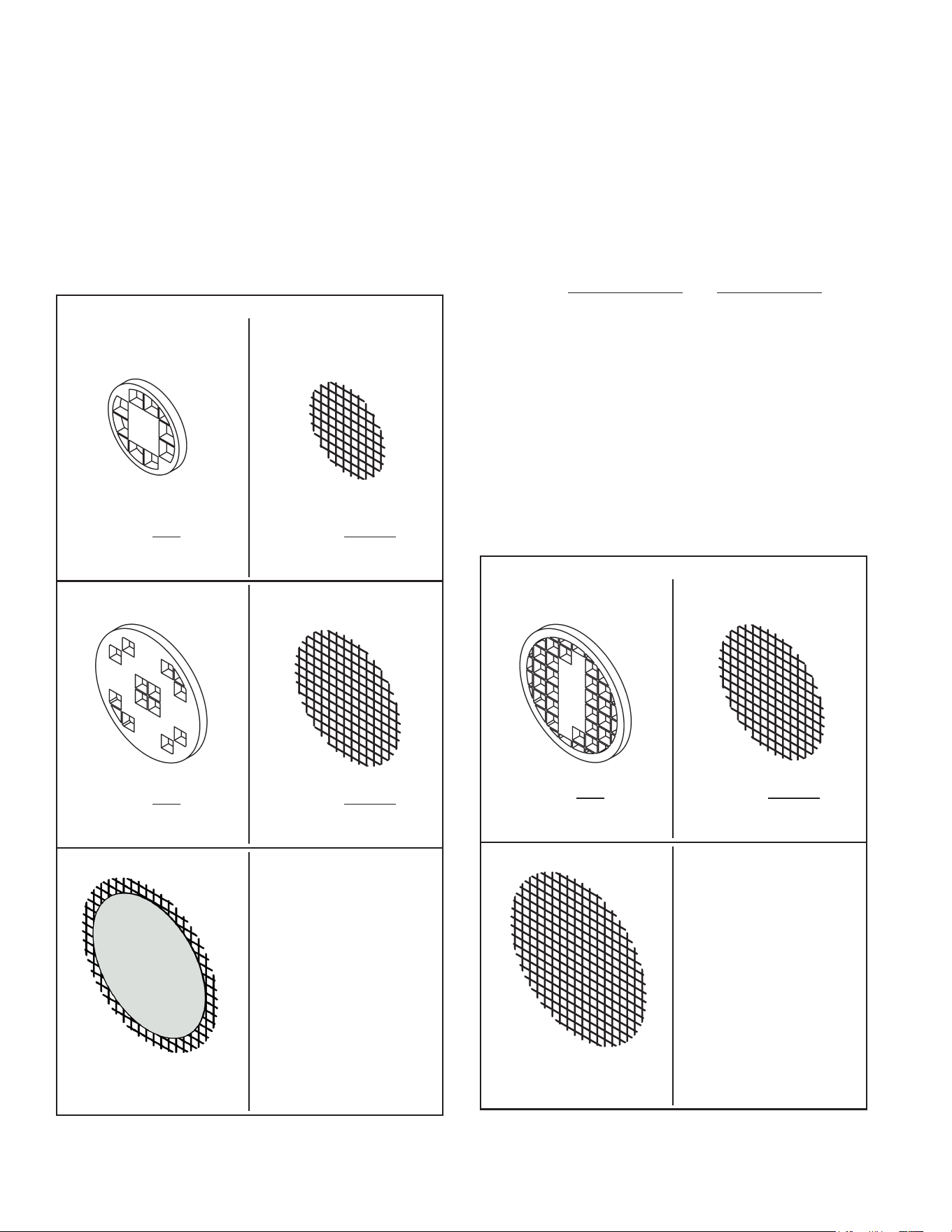
Venting terminations and sizing
• RefertoFigure33andTable2forventpipematerials
and sizing. Examples of the vent terminations are
shown in Figure 34 & Figure 35. If the installation
requires a vent riser, suitable drainage must be
providedtoensurecondensationdoesnotaccumulate.
TerminationthrougharoofisshownFigure36.
• 40,50and60gallonheaterswithratedinputsof50k
Btu/hrorlessaresuppliedwitha2”-3”rubbercoupling
toattachtheventingtothebloweranda2”,45°vent
terminationelbow.
with2in.venting(short) with2in.venting(long)
For heaters with rated inputs of 50k Btu/hr or less:
VENT LENGTH LESS THAN OR
EQUALTO20EQUIVALENTFT.
USETHISSCREEN(SUPPLIED).
VENT LENGTH GREATER THAN
20EQUIVALENTFT.
USETHISSCREEN(SUPPLIED).
with4in.venting
VENT LENGTH GREATER THAN
125EQUIVALENTFT.
USETHISSCREEN(SUPPLIED).
with3in.venting
VENT LENGTH GREATER THAN
50EQUIVALENTFT.
USETHISSCREEN(SUPPLIED).
with3in.venting
VENT LENGTH LESS THAN OR
EQUALTO50EQUIVALENTFT.
USETHISSCREEN(SUPPLIED).
Figure 31.
• 50and75gallonheaterswitharatedinputof60kBtu/
hrormorearesuppliedwitha3”-3”rubbercoupling
toattachtheventingtothebloweranda3”,45°vent
terminationelbow.
• Suppliedwiththisheaterareseveralventtermination
screens(seeFigure31&Figure32).
Installedin the ventterminationelbow,the vent screen
is required to keep foreign objects, rodents and small
birds from entering the venting system. These screens
havebeensizedtoensuremaximumenergyeciencyof
theventsystembasedonthe“equivalentlength”ofthe
vent piping. CHOOSE ONLY the ONE SCREEN THAT
MATCHES YOUR VENTING CONFIGURATION (see
Figure31&Figure32).Howtodeterminethe“equivalent
length”isshowninFigure33andinTable2.
Vent screen installation
• Install the appropriate vent screen into the vent
terminationelbow.
• Gentlypushthescreenintotheterminationelbowuntil
itsitsagainsttheinsideshoulder.
• Themetalwirescreensareself-securing.
• Plastic screens must be secured with (2) drops of
silicone sealant.This willallow for easy removal for
inspectionandcleaning.
with4in.venting
VENT LENGTH GREATER THAN
50EQUIVALENTFT.
USE THIS SCREEN
(SUPPLIED).
with3in.venting(short) with3in.venting(long)
For heaters with rated inputs of 60k Btu/hr or more:
VENT LENGTH LESS THAN OR
EQUALTO20EQUIVALENTFT.
USETHISSCREEN(SUPPLIED).
VENT LENGTH GREATER THAN
20EQUIVALENTFT.
USETHISSCREEN(SUPPLIED).
Figure 32.
31
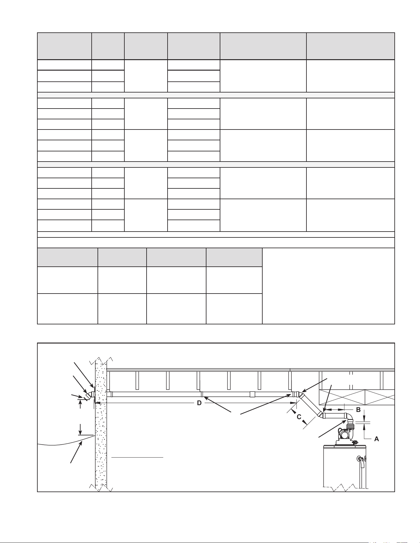
Calculating Equivalent Feet
WATER
HEATER
MODEL
HEATER
INPUT
(Btu/hr)
VENT SIZE
(Inside
Diam.)
PRESSURE
SWITCH
SETTING
MAXIMUM EQUIVALENT
VENT LENGTH
MINIMUM EQUIVALENT
VENT LENGTH
40&50gal. 40,000
2”
-0.27in.w.c.
50ft.+terminationelbow 7ft.terminationelbow
60gal. 42,000 -0.27in.w.c.
40&50gal. 50,000 -0.37in.w.c
40&50gal. 40,000
3”
-0.27in.w.c.
125ft.+terminationelbow 7ft.terminationelbow60gal. 42,000 -0.27in.w.c.
40&50gal. 50,000 -0.37in.w.c.
50gal.(short) 62,000
3”
-0.99in.w.c.
50ft.+terminationelbow 7ft.+terminationelbow50gal.(tall) 65,000 -0.99in.w.c.
75gal. 72,000 -0.99in.w.c.
40&50gal. 40,000
4”
-0.27in.w.c.
180ft.+terminationelbow 125ft.+terminationelbow60gal. 42,000 -0.27in.w.c.
40&50gal. 50,000 -0.37in.w.c.
50gal.(short) 62,000
4”
-0.99in.w.c.
125ft.+terminationelbow 50ft.+terminationelbow
50gal.(tall) 65,000 -0.99in.w.c.
75gal. 72,000 -0.99in.w.c.
EquivalentlengthsofstraightpipeforvariouselbowsusingSchedule40PVC,CPVCandpolypropylene.
Size Type
Short Sweep/
Short Radius
Long Sweep/
Long Radius
Notes:
1. Uselongradiuselbowswhere
possible.Minimumdistancebetween
90ºelbowsshouldbe6”wherever
possible.
2. Ventingsystemsmayuseamaximum
ofve(5)90°elbows.
3. Useproperscreentermination(see
Figure31&Figure32).
2”
3"
4"
90°elbow 8ft. 5ft.
2”
3"
4"
45°elbow 4ft. 2.5ft.
Table 2.
Exampleforcalculatingequivalentfeet.
Section“A” 0.5ft.
90°elbow 8.0ft.
SectionB 1.0ft.
45°elbow 4.0ft.
SectionC 1.5ft.
45°elbow 4.0ft.
SectionD 15.0ft.
TotalEquivalent 34.0ft.
Basedonthisexampleusethe(fullyopen)rodent
screenforventlengthgreaterthan20equivalentft.
(seeFigure31&Figure32).
Note:Theventpipemustbesupportedevery4ft..Topreventvibrationandsagging,itisrecommendedtouse
isolationpadswhenattachingstrapstooorjoists,wallsorceilings.PVCandCPVCventpipeshouldbesloped
upwardsawayfromtheblowerassemblyatapitchof1/8in.riseper4ft..Polypropyleneventsystemsrequirea
1/4”per1ft.upwardslopetoensureproperdrainage.
STRAP
45°SHORT
ELBOW
90°SHORT
ELBOW
RODENT
SCREEN
(INSTALL INTO
ELBOW)
TERMINATION
ELBOW
GROUND LEVEL
12”MIN.ORABOVE
ANTICIPATED SNOW
LEVEL.
COVER PLATE
(OPTIONAL)
Figure 33.
32
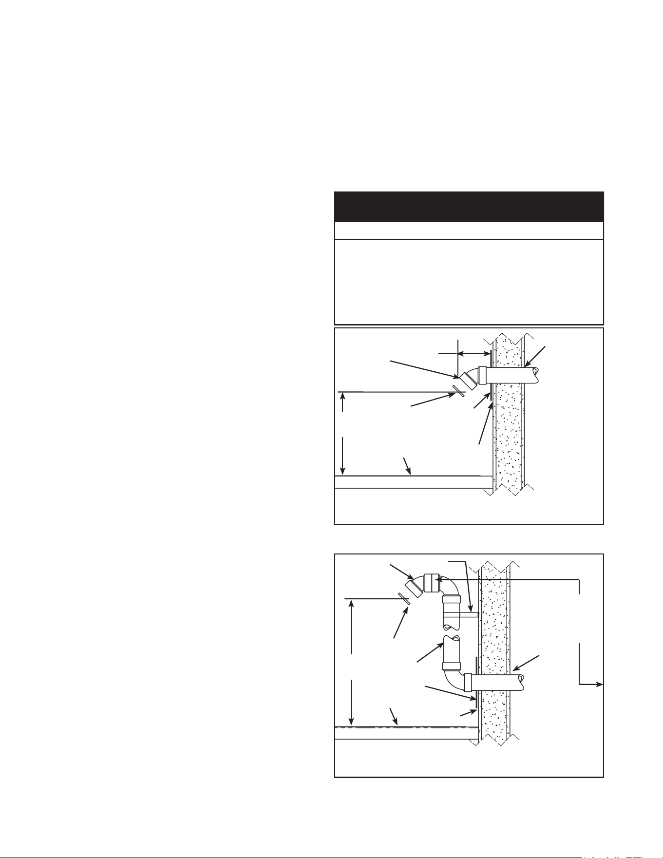
Venting instructions
1. Plantheventinglayoutstartingattheventtermination
andworkbacktowardtheheater.Takeintoconsideration
thestyleandpositionoftheventtermination,thevent
piperouting,elbowsandconnectorsrequiredandthe
necessarysupporthangers.
2. Ventingshouldbeasdirectaspossiblewiththefewest
numberofttings.Uselongradius45degreeandlong
radius90degreeelbowswhereverpossible.
3. Avoidusing90degreeelbows“backtoback”anddo
notusestreetelbows.Maintainaminimum6”straight
sectionbetweenelbows.Closelycoupledandshort
radiuselbowsreducetheventingcapacity.Figure30
showsexamplesofventpipeconnections.
4. DO NOT USE AN ELBOW AS A SUPPORT POINT.
Elbowsarenot designedtocarrythe weightofthe
ventingsystem.
5. Calculate“EquivalentVentLength”beforestarting.Do
notexceedthevaluesshowninTable2.Anexample
ofhowthislengthisdeterminedisshowninFigure
33.Thevaluefromyourcalculationsshouldalsobe
usedtodeterminewhichrodentscreentoinstallinto
theventterminationelbow.
6. Measuretheventpipingandcuttorequiredlengths.
Pipes must be cut at right angles and deburred to
ensurea good smootht with sucientoverlap for
thegluejoints.Correctanyinterferenceconditions.
7. Provide support hangers for horizontal vent piping
every 4 ft. to prevent sagging and stress. Provide
a minimum of 1/8” rise per 4 ft. of vent piping to
ensure adequate drainage (polypropylene vent
systemsrequirea1/4in.riseper1ft.ofventpipe).
Horizontalventpipingmustnotsagtoformvalleys
wherecondensatecancollect.Verticalventingshall
be supported every 5 ft.. Use appropriate support
strapsandvibrationisolators(foampads)onstraight
sectionsonly.Allowsucientclearanceforexpansion
andcontractionoftheventingsystem.
8. Atthepointwheretheventingexitsthebuilding,cuta
2-1/2”holefor2”venting,a3-1/2”holefor3”ventingor
a4-1/2”holefor4”venting.Forsidewallapplications,
usetheappropriatemetalcoverplateasatemplate
to mark the hole for the vent pipe to pass through
thewall.BEWAREOFCONCEALEDWIRINGAND
PIPING INSIDE THE WALL.
9. Inserttheventpipingthroughthisholeandsecureinto
position.Connecttheventpipetotheendtermination
elbowasshowninFigure34thruFigure36.
10. Drytallventpipes,elbows,connectorsandttings
beforejoininganypartswithsolventcement.PARTS
MUST FIT WITHOUT STRESS OR BENDING OF
ANY SECTION and each connection must overlap
a minimum of 1/2”. Do not force fit any of the
connections.Useonlytheappropriatesolventcement.
Caution: Solvent cements may produce
flammable vapors. Use only in well-ventilated
areas and keep away from all sources of ignition.
Note:DONOTusesolventcementonpolypropylene
ventsystems.
11. Installtheproperlysizedrodentscreenintotheoutlet
elbow and secure with a small quantity of silicone
sealant.RefertoFigure31&Figure32todetermine
theproperscreen.
12. Donotsealtheventpipingtothewalluntiltheventing
isproperlyconnectedtotheblowerassembly.
13. Completetheventinginstallationbysealingaround
the termination assembly where it passes through
theoutsidewall,insideandout,withsiliconeorother
suitablesealant.Applyenoughsealanttosecurethe
(optional)coverplatetothewall.
• Use only in well-ventilated areas.
• Do not use near flame or open fire.
• Use only the Solvent Cement and Primer appropriate for
the venting material being used.
• Solvent cements for plastic pipe are flammable liquids and
must be kept away from all sources of ignition.
Use of Solvent Cement and Primer
CAUTION
SEALANT
SEALANT
(UNDER
PLATE)
GROUND
LEVEL*
RODENT
SCREEN
(INSTALL
INTO
ELBOW)
* WHERE SNOW COVER IS NORMAL DURING
WINTER, ENSURE OUTLET IS INSTALLED
ABOVE ANTICIPATED SNOW LEVEL.
12”
MIN.*
ATTACH
TERMINATION
ELBOW (MAY
ALSOBE90°)
6”
VENT PIPING MAY
BE SLOPED IN ANY
DIRECTION, AS
LONG AS A WATER
TRAP IS NOT
CREATED IN THE
VENTING SYSTEM.
THE SLOPE
SHOULDBEKEPT
TO A MINIMUM
SO AS NOT TO
EXERT ANY UNDUE
STRESS ON THE
PIPE.
COVER PLATE
(OPTIONAL)
Figure 34.
BRACKET
VENT
RISER
SEALANT
SEALANT
(UNDER
PLATE)
ATTACH
TERMINATION
ELBOW (MAY
ALSOBE90°)
GROUND
LEVEL*
RODENT
SCREEN
(INSTALL
INTO
ELBOW)
VENT PIPING TO BE
SLOPED(DOWN)
TOWARD HEATER
TO PREVENT
WATER FROM
COLLECTING
(MAY REQUIRE
A CONDENSATE
TEE).
EQUIVALENT
VENT LENGTH
MEASURED
FROM THIS
POSITION
* WHERE SNOW COVER IS NORMAL DURING
WINTER, ENSURE OUTLET IS INSTALLED ABOVE
ANTICIPATED SNOW LEVEL.
12”MIN.*
COVER PLATE
(OPTIONAL)
Figure 35.
33
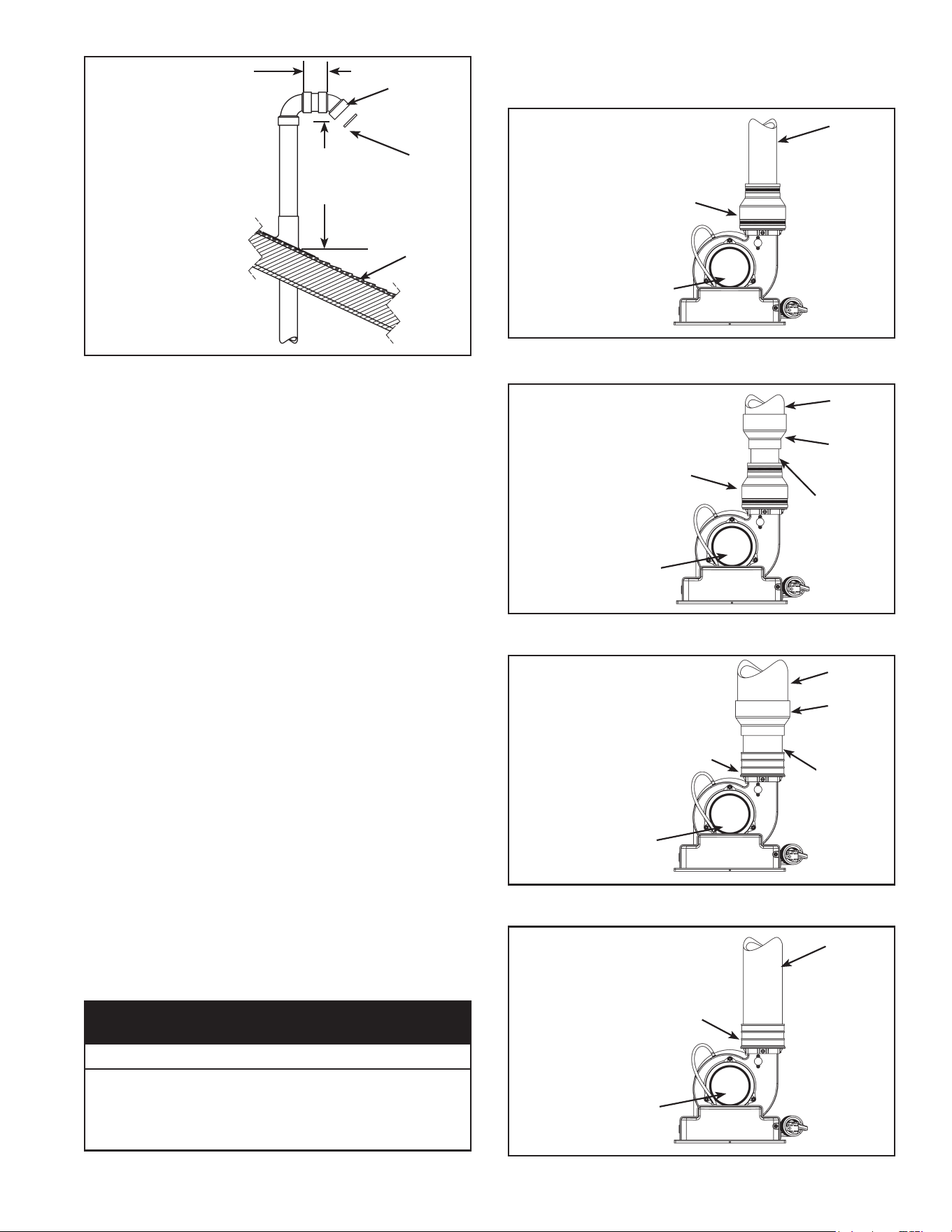
TERMINATION
MAYBE90°
ELBOW
3”MIN.
LENGTH
ROOF
LINE
A VENT USED IN A
SPECIAL VENTING
SYSTEM WITH POSITIVE
VENT PRESSURE AND
PASSING THROUGH A
ROOF SHALL EXTEND AT
LEAST18”ABOVETHE
HIGHEST POINT WHERE
IT PASSES THROUGH THE
ROOF SURFACE AND ANY
OTHER OBSTRUCTION
WITHINAHORIZONTAL
DISTANCEOF18”.A
VERTICAL VENTING
SYSTEM MUST BE
SUPPORTEDEVERY5ft..
18”OR
ABOVE
ANTICIPATED
SNOW LEVEL
RODENT
SCREEN
(INSTALL
INTO
ELBOW)
Figure 36.
Vent pipe connection to blower
1. The plastic vent piping connects into the rubber
couplinglocatedonthetopoftheblowerassembly.
This coupling includes gear clamps to connect the
venting to the blower. These connections must be
properlyseatedandtightenedtopreventtheleakage
ofuegasesintothearea.SeeFigure37thruFigure
41.
2. The40,50and60-gallonheaterswithratedinputsof
50kBtu/hrorlessaredesignedandsuppliedwitha
2”rubbercouplingtoaccepttheventpipe.
3. The50and75-gallonmodelswithratedinputsof60k
Btu/hrormorearesuppliedwitha3”rubbercoupling
to accept the vent pipe. Note: Polypropylene vent
systemsrequireseparateadaptor.
4. Beforeinstallingcleanandlightlysandtheendofthe
PVC/CPVCplasticventpipingthatwillconnectinto
therubbercoupling.Forpolypropyleneventsystems
followmanufacturer’sinstructions.
5. Loosentheupperclampontherubbercouplingand
insertthesandedendoftheventpipingafull1-1/4”.
Do not use glue or sealant in the rubber coupling.
Checkthatthereisnostressontheconnectionorthe
ventpipingthatmaybecausedbytwistingorbending.
6. Tighten the upper clamp so that the vent piping is
rmlysecuredinthecouplingandisgastight.Donot
overtightenorcausedistortionofanyoftheparts.
Ensure the bottom of the rubber coupling is rmly
seatedonthebloweroutletandthatthelowergear
clamp is also secure. Check to ensure there is no
distortionormovementoftheclampedassemblyonce
itiscompleted.
• Do not overtighten the top and bottom gear clamps of the
rubber coupling.
• Do not apply solvent cement or silicone to the rubber
coupling connection.
Property Damage Hazard
CAUTION
Dierent coupling installations according to vent
sizes
BLOWER
2”VENT
PIPE
2”RUBBER
COUPLING
(SUPPLIED)
CONFIGURATION
FOR40,50AND
60-GALLON(LO-
INPUT)HEATERS
CONNECTED TO
2" VENTING.
Figure 37.
2”RUBBER
COUPLING
(SUPPLIED)
BLOWER
3”VENT
PIPE
2”-3”
ADAPTER*
(FIELD
SUPPLIED)
2”VENTPIPE,
75mm(3in.)
MAX LENGTH
CONFIGURATION
FOR40,50AND
60-GALLON(LO-
INPUT)HEATERS
CONNECTED TO
3”VENTING.
*FOR3”DIRECT
CONNECTION TO
THE BLOWER,
ORDER
COUPLINGKit#
9008311005
(SEEALSOFigure
41).
Figure 38.
4”VENT
PIPE
3”RUBBER
COUPLING
(ORDER COUPLING
Kit#9008311005
TOREPLACE2”
RUBBER COUPLING
SUPPLIED.)
3”VENTPIPE,
3in.MAX
LENGTH
3”-4”
ADAPTER
(FIELD
SUPPLIED)
BLOWER
CONFIGURATION
FORLO-INPUT
HEATERS
CONNECTED TO
4”VENTING.
LOW-INPUT
HEATERS ARE
SUPPLIED WITH
A2”RUBBER
COUPLING.
Figure 39.
3”VENT
PIPE
3”RUBBER
COUPLING
(SUPPLIED)
BLOWER
CONFIGURATION
FORHI-INPUT
HEATERS
CONNECTED TO
3”VENTING.
(OPTIONAL
CONFIGURATION
FORLO-INPUT
HEATERS
CONNECTED TO
3”VENTING.)
Figure 40.
34
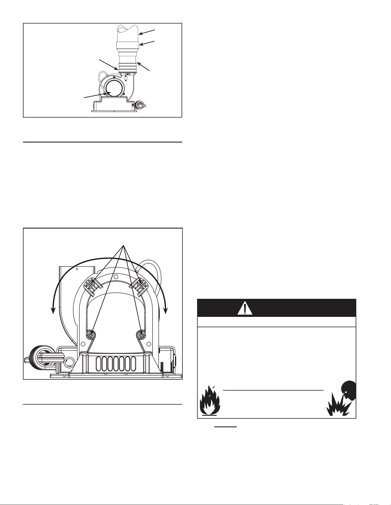
4”VENT
PIPE
3”RUBBER
COUPLING
(SUPPLIED)
3”VENTPIPE,
3in.MAX
LENGTH
3”-4”
ADAPTER
(FIELD
SUPPLIED)
BLOWER
CONFIGURATION
FORHI-INPUT
HEATER
CONNECTED TO
4”VENTING.
Figure 41.
BLOWER EXHAUST DIRECTION
Theblowerassemblymayberotated90degreeclockwise
orcounterclockwisetoallowhorizontalventinginareas
havingrestrictedspaceabovethewaterheater.Torotate
thebloweroutlet,removethefournuts(with11/32”nut
driver)(seeFigure42),securingtheuecollectortothe
blowerhousing.Pulltheblowerassemblyforwardtofree
it from the mounting studs. Rotate the blower housing
clockwiseorcounter-clockwiseandalignthefourholes
andscrewstogether.Reattachtheblowerhousingtothe
uecollector.
11/32”nut
Note:Couplingtoventsystem
notshownforclarity.
Figure 42.
VENT PIPE PREPARATION
1. INITIALPREPARATION
• Makesurethesolventcementyouareplanningto
useisdesignedforthespecicapplicationyouare
attempting.
• Knowthephysicalandchemicalcharacteristicsand
limitationsofthePVCandCPVCpipingmaterials
thatyouareabouttouse.
• Knowthereputationofyourmanufacturerandtheir
products.
• Know your own qualifications or those of your
contractor.Thesolventweldingtechniqueofjoining
PVCandCPVCpipeisaspecializedskilljustasany
otherpipettingtechnique.
• Closely supervisethe installation andinspect the
nishedjobbeforestart-up.
• Contact the manufacturer, supplier,or competent
consultingagencyifyouhaveanyquestionsabout
the application or installation of PVC and CPVC
pipe.
• Take thetimeandeorttodoaprofessional job.
Shortcutswillonlycauseyouproblemsanddelays
instart-up.Byfar,themajorityoffailuresinPVCand
CPVC systems are the result of shortcuts and/or
improperjoiningtechniques.
2. SELECTION OF MATERIALS (PCV and CPVC
VENTING)
• CuttingDevice-SaworPipeCutter
• DeburringTool,Knife,File,orBevelingMachine(2”
andabove)
• Brush-PureBristle
• Rag-Cotton(NotSynthetic)
• PrimerandCleaner
• SolventCement-PVCforPVCComponentsand
CPVCforCPVCComponentsonly
• Containers - Metal or Glass to hold Primer and
Cement.SelectthetypeofPVCorCPVCmaterials
to be used on the basis of their application with
respect to chemical resistance, pressure rating,
temperaturecharacteristics,etc.
• InsertionTool-Helpfulforlargerdiameterpipeand
ttings6”andabove.
Read instruction manual before
installing, using or servicing
water heater.
• Do not store or use gasoline or other flammable vapors and
liquids in the vicinity of this or any other appliance.
• Avoid all ignition sources if you smell gas.
• Do not expose water heater control to excessive gas
pressure.
• Use only gas shown on rating plate.
• Maintain required clearances to combustibles.
• Keep ignition sources away from faucets after extended
period of non-use.
Fire or Explosion Hazard
WARNING
Primer:
ItisrecommendedthatTetrahydrofuran(THF)be
usedtopreparethesurfacesofpipeandttingsfor
solventwelding.Donotusewater,rags,gasoline
oranyothersubstitutesforcleaningPVCorCPVC
surfaces.AchemicalcleanersuchasMEKmaybe
used.
35
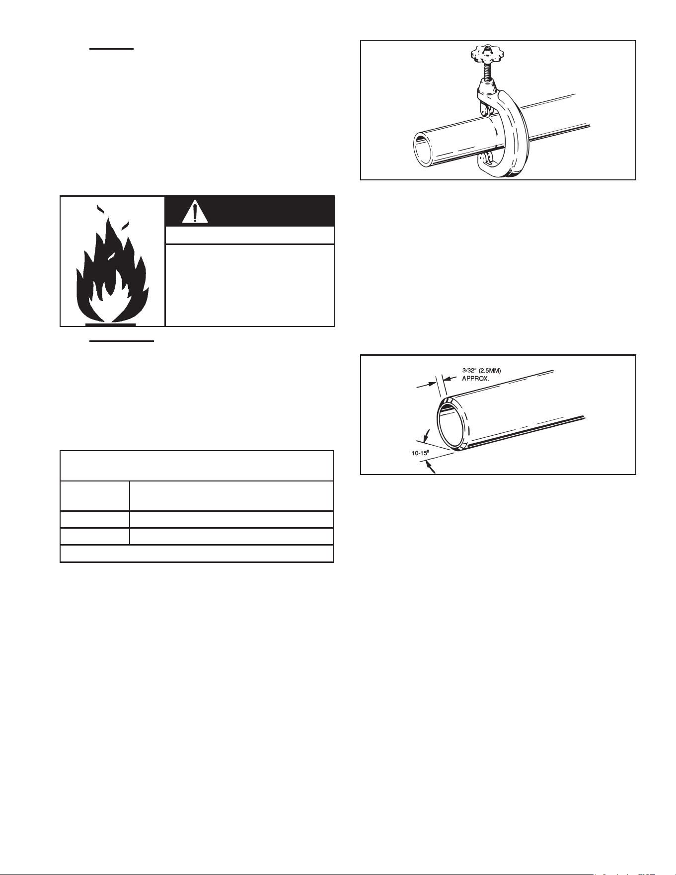
Cement:
The cement should be a bodied cement of
approximately 500 to 1600 centipoise viscosity
containing10-20%(byweight)virginPVCmaterial
solvated with Tetrahydrofuran (THF). Small
quantities of Dimethyl Formamide (DMF) may
beincludedtoactasaretardingagenttoextend
curing time. Select the proper cement; Schedule
40cementshouldbeusedforSchedule40 pipe.
Neveruseall-purposecements,commercialglues
andadhesivesorABScementtojoinPVCorCPVC
pipeandttings.
• Primers and cements are
extremely flammable, and must
not be stored or used near heat
or open flame.
• Also, use only in a well venti-
lated area.
Fire Hazard
WARNING
Applicators:
Selectasuitablepurebristletypepaintbrush.Use
aproperwidthbrushorrollertoapplytheprimer
andcement(seechartbelow).Speedyapplication
of cement is important due to its fast drying
characteristics.IMPORTANTNOTE:Adaubertype
applicatorshouldonlybeusedonpipesizes2”and
below. Forlarger diameterpipe, a brushor roller
mustbeused.
RECOMMENDEDBRUSH*SIZEFOR
PRIMER AND CEMENT APPLICATIONS
Nominal
Pipe(IPS)
BrushSize
2 1.5”
3 1.5”-2.5”
*USE ONLY NATURAL BRISTLE
Table 3.
3. MAKINGTHEJOINT
A. Cutting
Pipemustbesquarelycuttoallowfortheproper
interfacing of the pipe end and the tting socket
bottom.Thiscanbeaccomplishedwithamiterbox
saworwheeltypecutter.Wheeltypecuttersarenot
generallyrecommendedforlargerdiameterssince
theytendtoarethecornerofthepipeend.Ifthis
typeofcutterisused,theareontheendmustbe
completelyremoved.
Note:Powersaws,ifused,shouldbespecically
designedtocutplasticpipe.
Figure 43.
B. Deburring
Use a knife, plastic pipe deburring tool, or le to
removeburrsfromtheendofsmalldiameterpipe.
Besuretoremoveallburrsfromaroundtheinside
aswellastheoutsideofthepipe.Aslightchamfer
(bevel)ofabout10°-15°shouldbeaddedtotheend
topermiteasierinsertionofthepipeintotheendof
thetting.Failuretochamfertheedgeofthepipe
mayremovecementfromthettingsocket,causing
thejointtoleak.
Figure 44.
C. Test dry t of the joint
Tapered fitting sockets are designed so that
an interfaced t should occur when the pipe is
insertedabout1/3to2/3ofthewayintothesocket.
Occasionally,when pipetting dimensions are at
thetoleranceextremes,it willbepossibleto fully
insertdrypipe to thebottomofthe ttingsocket.
Whenthishappens,asucientquantityofcement
mustbeappliedtothejointtollthegapbetween
thepipeandtting.Thegapmustbelledtoobtain
astrong,leak-freejoint.
36
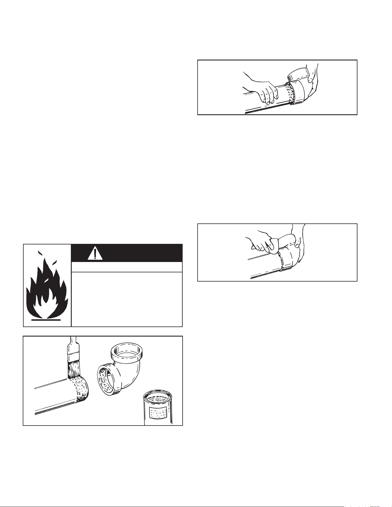
D. Inspection, cleaning, priming
Visually inspect the inside of the pipe and tting
sockets and remove all dirt, grease or moisture
with a clean dry rag. If wiping fails to clean the
surfaces,achemicalcleanermustbeused.Check
forpossibledamagesuchassplitsorcracksand
replaceifnecessary.
Depth-of-entry
Markingthedepthofentryisawaytocheckifthe
pipe has reached thebottom of thetting socket
inStepF.Measurethettingdepthandmarkthis
distance on the pipe O.D. You may want to add
severalinchestothedistanceandmakeasecond
mark as the primer and cement will most likely
destroyyourrstone.
Applyprimertothesurfaceofthepipeandtting
socket with a natural bristle brush.This process
softens and prepares the PVC or CPVC for the
solventcementingstep.Movequicklyandwithout
hesitation to the cementing procedure while the
surfacesarestillwetwithprimer.
E. Application of solvent cement
• Apply solvent cement evenly and quickly around
outsideofpipe atawidthalittlegreaterthanthe
depthofthettingsocket.
• Applyalightcoatofcementevenlyaroundtheinside
ofthettingsocket.Avoidpuddling.
• Applyasecondcoatofcementtothepipeend.
• Cans of cement and primer should
be closed at all times when not in
use to prevent evaporation of
chemicals and hardening of cement.
• They are also very flammable and
should be kept away from heat or
flame.
Fire Hazard
WARNING
Figure 45.
F. Joint assembly
Workingquickly,insertthepipeintothettingsocket
bottomandgivethepipeorttinga1/4turntoevenly
distributethecement.Donotcontinuetorotatethe
pipeafterithashitthebottomofthettingsocket.
Agoodjointwillhavesucientcementtomakea
beadallthewayaroundtheoutsideofthettinghub.
Thettingwillhaveatendencytoslidebackwhile
thecementisstillwetsoholdthejointtogetherfor
about15seconds.
Figure 46.
G. Cleanup and joint movement
Remove allexcess cement fromaround thepipe
andttingwithadrycottonrag.Thismustbedone
whilethecementisstillsoft.
Thejointshouldnotbedisturbedimmediatelyafter
thecementingprocedure,andsucienttimeshould
beallowedforpropercuringofthejoint.Exactdrying
time is dicult to predict because it depends on
variablessuchastemperature,humidityandcement
integrity.Formorespecicinformation,youshould
contactyoursolventcementmanufacturer.
Figure 47.
37
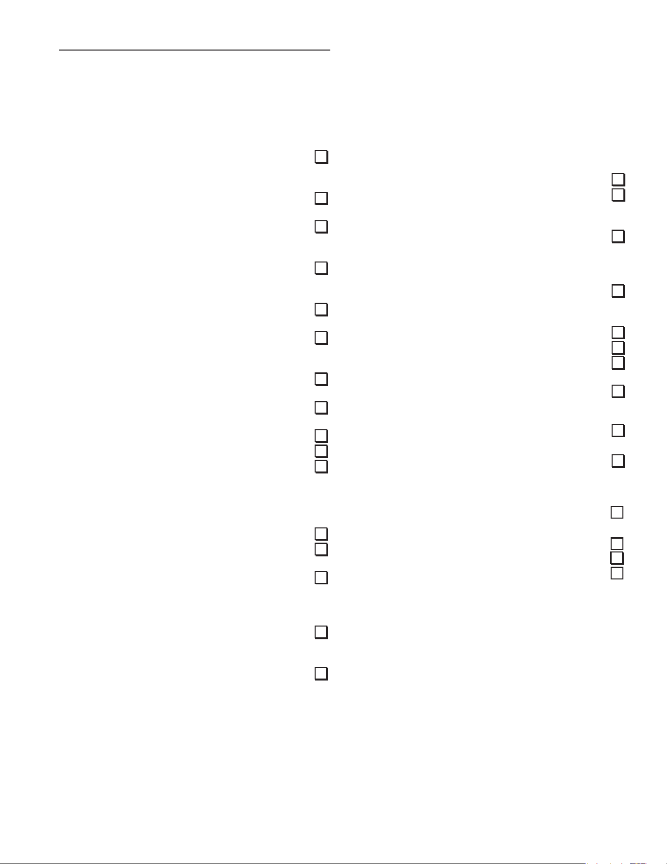
INSTALLATION CHECKLIST
Note:Useandcompletethischecklistbeforelightingthe
heater. Correct any conditions that do not meet these
instructions.
Vent Termination
Horizontal
1. 12in.min.abovegrade/snowlevel.
2. Awayfromcorners,othervents,windowsetc.
Vertical
1. Exhaust vent termination 18 in. min. above
roof/snowlevel.
Water System Piping
1. TemperatureandPressurereliefvalveproperly
installedwithadischargelineruntoanopen
drainandprotectedfromfreezing.
2. Allpipingproperlyinstalledandfreeofleaks.
3. Heatercompletelylledwithwater.
4. Closedsystempressurebuild-upprecautions
installed.
5. All components used in combo heating
systemsorrecirculationloopsystemssuitable
forpotablewater.
6. Checkvalvesinstalledincomboheatingand
recirculationloopsystems.
7. ThermostaticMixingValvesateachpoint-of-
use.
Electrical Connections
1. Unitconnectedtoadedicated120Velectrical
supply.
2. Properpolarity.
3. Waterheaterproperlygrounded.
4. Installed in accordance with prevailing
provisionsoflocalcodes,orintheabsenceof
such,thelatesteditionof“National Electrical
Code” (NFPA 70)”.
After all actions on checklist are checked/
completed, read the Lighting Instructions and
proceed with lighting the heater.
CheckHere
Water Heater Location
1. Centrallylocatedwiththewaterpipingsystem.
Locatedasclosetogaspipingandventpipe
systemaspossible.
2. Located indoors and in a vertical position.
Protectedfromfreezingtemperatures.
3. Properclearancesfromcombustiblesurfaces
maintained and not installed directly on a
carpetedoor.
4. Provisionsmadetoprotecttheareafromwater
damage.Metaldrainpaninstalledandpiped
toanadequatedrain.
5. Installationareafreeofcorrosiveelementsand
ammablematerial.
6. Sucientroomtoservicethewaterheater.
Gas Supply and Piping
1. Gassupplyisthesametypeaslistedonthe
waterheaterdataplate.
2. Gas line equipped with shut-o valve, union
anddirtleg
3. Approvedpipejointcompoundused.
4. Adequatepipesizeandofapprovedmaterial.
5. Chloride-freesoapandwatersolutionorother
approvedmeansusedtocheckallconnections
andttingsforpossiblegasleaks.
Vent Pipe System
1. Ventpipeandttingsofapprovedmaterial.
2. Acceptablesize,lengthandnumberofelbows
onexhaustventsystem.
3. Installed in accordance with prevailing
provisionsoflocalcodes,orintheabsenceof
such,thelatesteditionof“National Fuel Gas
Code” ANSI Z223.1 (NFPA 54).
4. Horizontalpipingslopesatanupwardpitchof
1/8in.riseper4ft.awayfromthewaterheater.
5. Notobstructedinanyway.
CheckHere
38
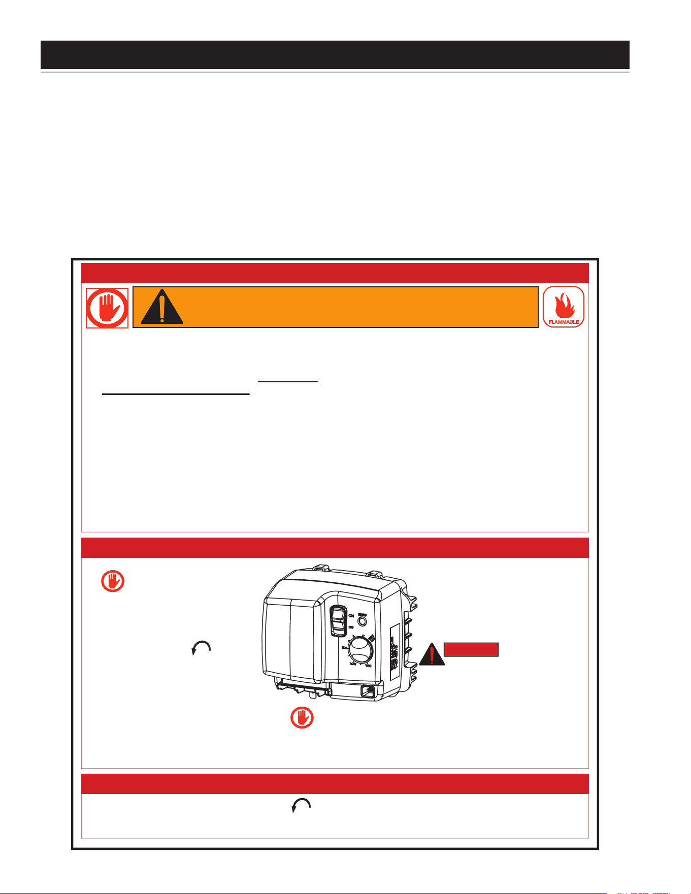
Readandunderstandthesedirectionsthoroughlybeforeattemptingtooperatethewaterheater.Makesuretheburner
viewportisnotmissingordamaged.Makesurethetankiscompletelylledwithwaterbeforeoperatingthewaterheater.
Thegascontrolvalve/thermostathasan“On/OSwitch”andmustbeturnedonbeforethewaterheaterisoperational.
Checkthelabelonthefrontofthewaterheaternearthegascontrolvalve/thermostatforthecorrectgas.Donotstart
thiswaterheaterwithanygasotherthantheonelistedonthelabel.Ifyouhaveanyquestionsordoubts,consultthe
gassupplierorgasutilitycompany.ThefollowingLightingInstructionlabelappearsonthefrontofthewaterheater.
ThisheaterisequippedwithaHoneywell/Resideogascontrol/thermostatandahot-surfaceigniter.Thiscontrolisa
combinationgasvalve,thermostatandignitioncontrollerforuseonthispowerventedwaterheater.Thevalvecontains
amicro-controllerthatsupervisestheignitionsequenceandmonitorsthetemperaturesettingsandoperationofthe
heater.Thecontrolleralsomonitorstheammablevaporsafetyfeaturesofthisheater.
This heater is equipped with a hot-surface ignition system that automatically ignites the burner. Do not attempt
to light this heater manually with a match or ame-producing device.
323546-000
1. Turn the thermostat counter-clockwise to the lowest setting.
2. Set the gas control switch to the “OFF” position.
3. Turn off electrical power to the appliance if service is to be performed.
TO TURN OFF GAS TO APPLIANCE
1. STOP! Read the safety
information above on this
label.
2. Turn off all electric power to the
appliance.
3. Turn the thermostat
counter-clockwise to the
lowest setting.
4. Set the switch on the control to
the “OFF” position.
5. Do not attempt to light manually.
6. Wait five (5) minutes to clear out
any gas. If you then smell gas, STOP!
Follow “B” in the safety information above on
this label. If you don't smell gas, go the next
step.
7. Turn on all electric power to
the appliance.
8. Set the switch on the control
to the “ON” position.
9. Turn thermostat to desired
setting.
DANGER Hotter water
increases the risk of
scald injury. Consult the
instruction manual before
changing temperature.
10. If the appliance will not operate, follow the
instructions “To Turn Off Gas To Appliance”
and call your service technician or gas
supplier.
OPERATING INSTRUCTIONS
DANGER
A. This appliance does not have a pilot. It is
equipped with an ignition device which
automatically lights the burner. Do NOT try
to light the burner by hand.
B. BEFORE OPERATING smell all around the
appliance area for gas. Be sure to smell next
to the floor because some gas is heavier
than air and will settle on the floor.
WHAT TO DO IF YOU SMELL GAS:
• Do not try to light any appliance.
• Do not touch any electric switch; Do not use
any phone in your building.
• Immediately call your gas supplier from a
neighbor's phone. Follow the gas suppliers
instructions.
• If you cannot reach your gas supplier, call the
fire department.
C. Use only your hand to turn the gas control
buttons. Never use tools. If the control
buttons will not turn, don't try to repair them,
call a qualified service technician. Force or
attempted repair may result in a fire or
explosion.
D. Do not use this appliance if any part has
been under water. Immediately contact a
qualified installer or service agency to
replace a flooded water heater. Do not
attempt to repair the unit. It must be
replaced!
BEFORE OPERATING: ENTIRE SYSTEM MUST BE FILLED WITH WATER AND AIR PURGED FROM ALL LINES.
FLAMMABLE
WARNING: If you do not follow these instructions exactly, a fire
or explosion may result causing property damage, personal
injury or loss of life.
FOR YOUR SAFETY READ BEFORE LIGHTING
Read and follow water heater warnings and instructions in furnished manual.
If manual is missing, you may obtain one free of charge by calling 1-800-821-2017.
Si Ud. no puede ni leer ni entender el inglés y si necesita manuales, etiquetas
o rótulos en español, Ud. los puede obtener si al llama 1-800-821-2017.
WARNING / ADVERTENCIA
HOT
BURN
Water temperature over 125°F can
cause severe burns instantly or
death from scalds.
Children, disabled and elderly are
at highest risk of being scalded.
See instruction manual before
setting temperature at water heater.
Feel water before bathing or
showering.
Temperature limiting valves are
available, see manual.
DANGER
Do not store or use gasoline or other flammable vapors and
liquids in the vicinity of this or any other appliance. Storage or
use of gasoline or other flammable vapors or liquids in the
vicinity of this or any other appliance can result in serious injury
or death.
Can result in serious injury or death
FIRE AND EXPLOSION HAZARD
Flammable Vapors
FLAMMABLES
WARNING
LIGHTING INSTRUCTIONS
39
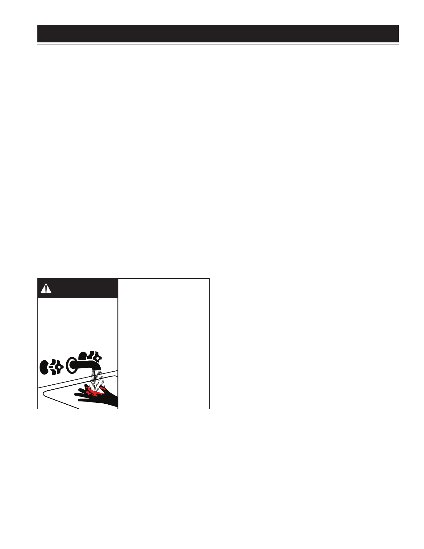
Install Thermostatic Mixing Valves to regulate the
temperature of the water supplied to each point-of-use
(for example, kitchen sink, bathroom sink, bath and
shower).Installandadjustthemixingvalveaccordingto
itsmanufacturer’sinstructions.
Itisrecommendedthatlowerwatertemperaturesbeused
toavoidtheriskofscalding.Itisfurtherrecommended,
in all cases, that the water temperature be set for the
lowesttemperaturewhichsatisesyourhot-waterneeds.
Thiswillalsoprovidethemostenergyecientoperation
ofthewaterheater.
Shortrepeatedheatingcyclescausedbysmallhot-water
usescancauseatemperatureincreaseofthehotwater
by30F°higherthantheheater’stemperaturesettings.If
youexperiencethistypeofuseyoushouldconsiderusing
lowertemperaturesettingstoreducescaldhazards.
WARNING! Even if the water heater’s thermostat is set
to a relatively low temoerature, hot water can scald.
Install Thermostatic Mixing Valves at each point-of-use
to reduce the risk of scalding.
Shouldoverheatingoccurorthegassupplyfailstoshut
o, turn o the main manual gas shut o valve to the
appliance(seeFigure1).
Water temperature over
125°F can cause severe
burns instantly resulting in
severe injury or death.
Children, the elderly and the
disabled and are at highest
risk of scald injury.
Feel water before bathing or
showering.
Temperature limiting devices
such as mixing must be
installed when required by
codes and to ensure safe
temperatures at fixtures.
BURN
HOT
HOT
DANGER
HOTWATERCANSCALD:
Waterheatersareintendedtoproducehotwater.Water
heatedtoatemperaturewhichwillsatisfyspaceheating,
clotheswashing,dishwashing,andothersanitizingneeds
canscaldandpermanentlyinjureyouuponcontact.Some
peoplearemorelikelytobepermanentlyinjuredbyhot
waterthanothers.Theseincludetheelderly,children,the
inrmorphysically/mentallyhandicapped.Ifanyoneusing
hotwaterfromthis heater tsintooneofthese groups
orif thereis alocal code or state law requiring certain
temperature water at the hot-water tap, then you must
takespecialprecautions.Inadditiontousingthelowest
possibletemperaturesettingthatsatisesyourhot-water
needs,ameanssuchasamixingvalve,shouldbeused
atthehot-watertapsusedbythesepeopleoratthewater
heater. Mixing valves are available at plumbing supply
or hardware stores (see Figure 8 & Figure 9). Follow
manufacturer’sinstructionsforinstallationofthevalves.
Beforechangingthefactorysettingonthethermostat,in
thismanual,seeTable4.
The water heater should be located in an area where
the general public does not have access. If a suitable
areaisnotavailable,acovershouldbeinstalledoverthe
thermostattopreventtampering.
This water heater is equipped with an adjustable
thermostattocontrolwatertemperature(seeFigure48).
Hotwatertemperaturesrequiredforautomaticdishwasher
andlaundryusecancausescaldburnsresultinginserious
personalinjuryand/ordeath.Thetemperatureatwhich
injuryoccursvarieswiththeperson’sageandtimeofthe
exposure.Theslowerresponsetimeofchildren,agedor
disabledpersonsincreasesthehazardstothem.Never
allowsmallchildrentouseahot-watertap,ortodrawtheir
ownbathwater.Neverleaveachildordisabledperson
unattendedinabathtuborshower.
Thehotsettingshownonthedialisapproximately120°F.
Thisisagoodstartingpointtosetthetemperature.
Settingthewaterheatertemperatureat120°Fwillreduce
theriskofscalds.Somestatesrequiresettingsatspecic
lowertemperatures.
Thethermostatsettingsonthegascontrolvalveareshown
inFigure48.
Thewatertemperaturesettingwasfactorysetatthelowest
(VAC)temperaturesetting.
OPERATING THE TEMPERATURE CONTROL SYSTEM
40
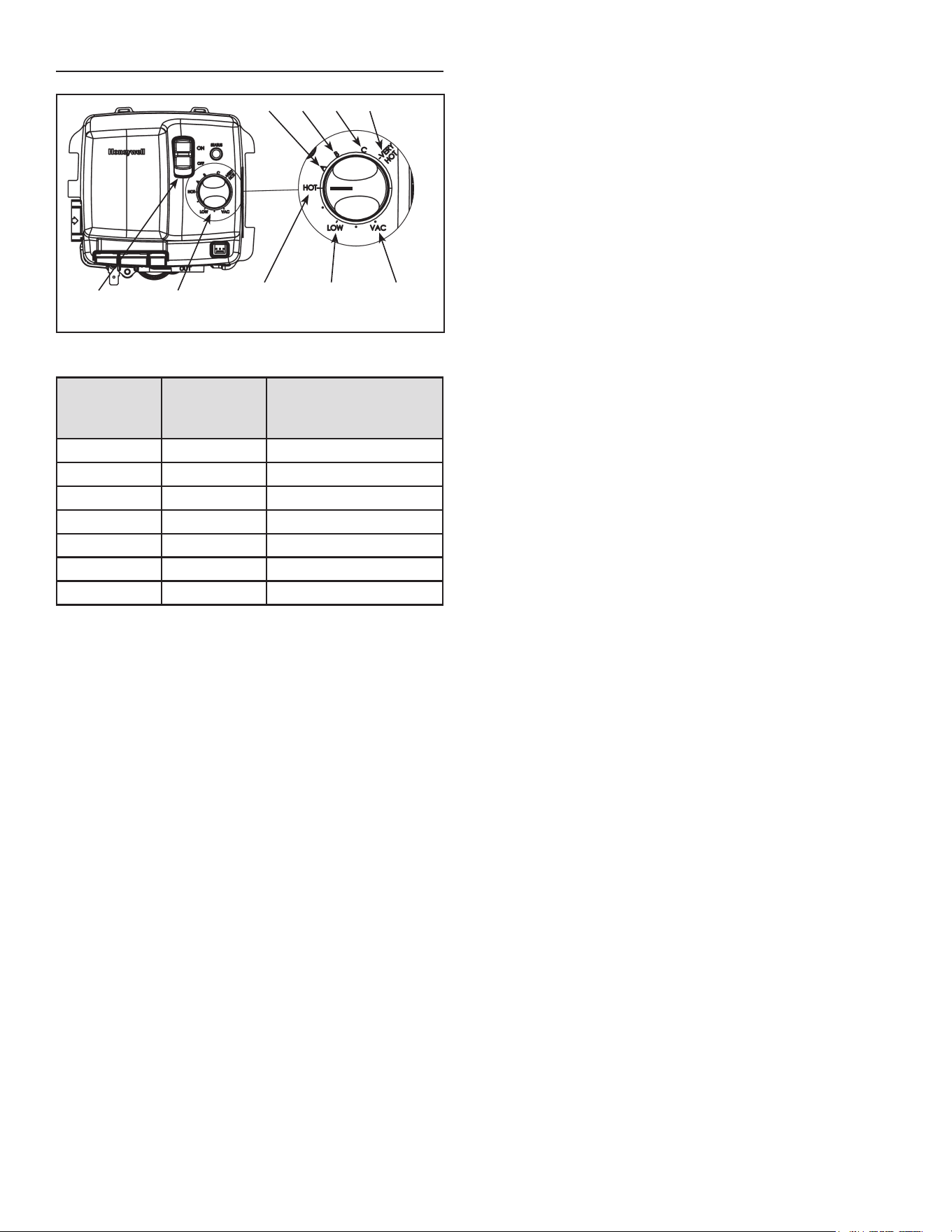
GAS CONTROL VALVE/THERMOSTAT
ON/OFF
SWITCH
TEMPERATURE
SETTING DIAL
155°F
70°F
130°F 140°F 150°F
120°F
110°F
Figure 48.
Temperature
Dial Setting
Approximate
Temperature
°F
Time to induce a 2nd
and 3rd Degree burn
to adult skin
VERY HOT 155 Lessthan1second
C 150 About1.5seconds
B 140 Lessthan5seconds
A 130 Morethan30seconds
HOT 120 Morethan5minutes
LOW 110 Normalshowertemp
VAC 70 N/A
Table 4.
WARNING! Higher temperatures increase the risk os
scalding, but even at 120°F, hot water can scald, (see
table 4). Install Thermostatic Mixing Valve(s) at each
point-of-use to reduce the risk of scalding.
Note:Thetemperaturesindicatedareapproximates.The
actualtemperatureoftheheatedwatermayvary.
The Vacation Setting (VAC) sets the controller at
approximately70°F.Thissettingisrecommendedwhen
thewaterheaterisnotinuseforalongperiodoftime.This
eectivelyturnsthecontrollertemperaturesettingdownto
atemperaturethatpreventsthewaterinthewaterheater
fromfreezingwhilestillconservingenergy.
41
START UP CONDITIONS
Condensate
Wheneverthewaterheaterislledwithcoldwater,some
condensate will form while the burner is ON.A water
heatermayappeartobeleakingwheninfactthewateris
condensate.Thisusuallyhappenswhen:
a. Anewwaterheaterislledwithcoldwaterfortherst
time.
b. Burninggasproduceswatervaporinwaterheaters,
particularly high efficiency models where flue
temperaturesarelower.
c. Largeamountsofhotwaterareusedinashorttime
andtherellwaterinthetankisverycold.
Moisturefromtheproductsofcombustioncondenseon
thecoolertanksurfacesandformdropsofwaterwhich
mayfallontotheburnerorotherhotsurfacestoproduce
a“sizzling”or“frying”noise.
Because of the suddenness and amount of water,
condensate water maybe diagnosed as a “tank leak”.
Afterthewaterinthetankwarmsup(about1-2hours),
theconditionshoulddisappear.
Donotassumethewaterheaterisleakinguntiltherehas
beenenoughtimeforthewaterinthetanktowarmup.
Anundersizedwaterheaterwillcausemorecondensation.
The water heater must be sized properly to meet the
family’s demands for hot water including dishwashers,
washingmachinesandshowerheads.
Excessive condensate maybe noticed during the
winter and early spring months when incoming water
temperaturesareattheirlowest.
Good venting is essential for a gas red water heater
to operate properly as well as to carry away products
ofcombustionandwatervapor(seealso“Condensate”
section).
Thermal expansion
See “Thermal Expansion” section elsewhere in this
manual.
• Avoid water heater damage.
• Install thermal expansion tank if necessary.
• Do not apply heat to cold water inlet.
• Contact qualified installer or service agency.
Property Damage Hazard
CAUTION
A properly-sized thermal expansion tank should be
installed on all closed systems to control the harmful
eects of thermal expansion. Contact a plumbing
service agency or your retail supplier regarding the
installation of a thermal expansion tank.
Closed water systems
See “Closed Water Systems” section elsewhere in this
manual.
Smoke/odor
Itisnotuncommontoexperienceasmallamountofsmoke
andodorduringtheinitialstart-up.Thisisduetoburningo
ofoilfrommetalparts,andwilldisappearinashortwhile.
Strange sounds
Possiblenoisesduetoexpansionandcontractionofsome
metalpartsduringperiodsofheat-upandcool-downdo
notnecessarilyrepresentharmfulordangerousconditions.
Condensation causes sizzling and popping within the
burnerareaduringheatingandcoolingperiodsandshould
beconsiderednormal.See“Condensate”sectioninthis
manual.
OPERATIONAL CONDITIONS
Smelly water
Each water heater contains at least one anode rod for
corrosionprotectionofthetank.Certainwaterconditions
willcauseareactionbetweenthisrodandthewater.The
mostcommoncomplaintassociatedwiththeanoderod
isoneofa“rotteneggsmell”inthehotwater.Thesmell
isaresultoffourfactorswhichmustallbepresentforthe
odortodevelop:
a. Aconcentrationofsulfateinthesupplywater.
b. Littleornodissolvedoxygeninthewater.
c. A sulfate reducing bacteria which has accumulated
within the water heater (this harmless bacteria is
nontoxictohumans).
d. Anexcessofactivehydrogeninthetank.Thisiscaused
bythecorrosionprotectiveactionoftheanode.
Smellywatermaybeeliminatedorreducedinsomewater
heatermodelsbyreplacingtheanode(s)withoneofless
activematerial,andthenchlorinatingthewaterheatertank
andallwaterlines.Contactthelocalwaterheatersupplier
orserviceagencyforfurtherinformationconcerningan
AnodeReplacementKitandthischlorinationtreatment.
Ifthesmellywaterpersistsaftertheanodereplacement
and chlorination treatment, we can only suggest that
chlorinationoraerationofthewatersupplybeconsidered
toeliminatethewaterproblem.
Do not remove the anode leaving the tank unprotected.
By doing so, all warranty on the water heater tank is
voided.
FOR YOUR INFORMATION
42
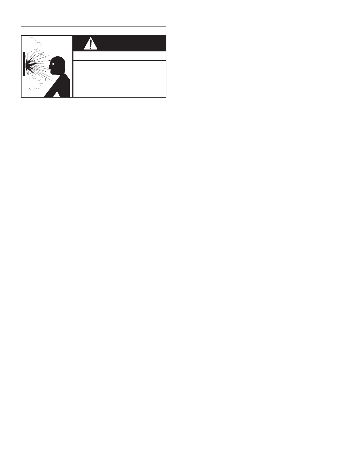
“AIR” IN HOT-WATER FAUCETS
• Flammable hydrogen gases may
be present.
• Keep all ignition sources away
from faucet when turning on hot
water.
Explosion Hazard
WARNING
HYDROGEN GAS: Hydrogen gas can be produced in
a hot-water system that has not been used for a long
periodoftime(generallytwoweeksormore).Hydrogen
gas is extremely ammable and explosive. To prevent
the possibility of injury under these conditions, it is
recommendedthatthehot-waterfaucet,locatedfarthest
away,beopenedforseveralminutesbeforeanyelectrical
applianceswhichareconnectedtothehot-watersystem
areused(suchasadishwasherorwashingmachine).If
hydrogengasispresent,therewillprobablybeanunusual
soundsimilartoairescapingthroughthepipeasthehot-
waterfaucetisopened.Theremustbenosmokingoropen
amenearthefaucetatthetimeitisopen.
43
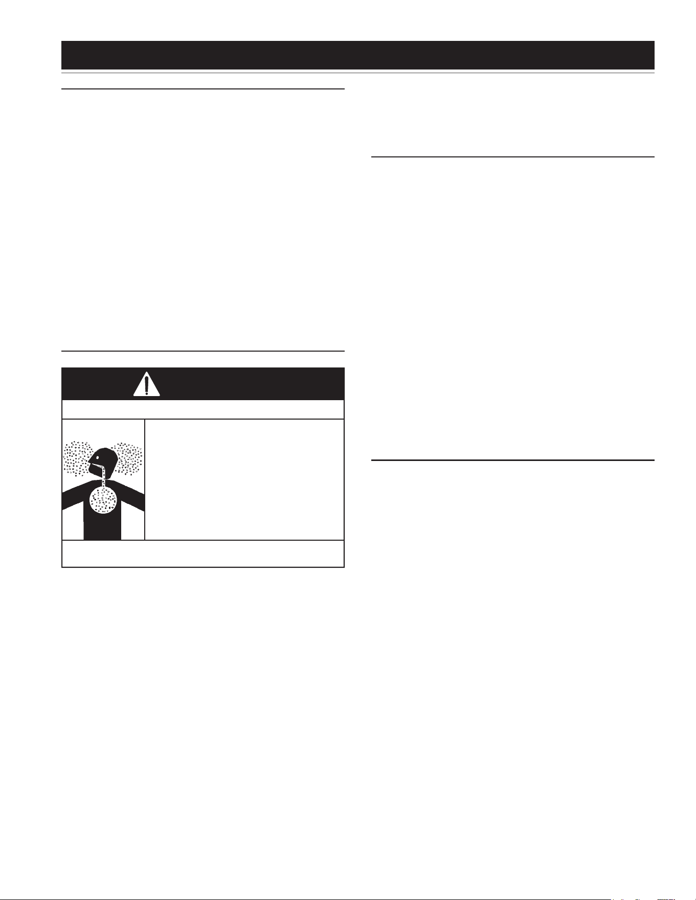
GENERAL UPKEEP
Makeitahabittolookaroundtheheater,theventpiping,
andthehotandcoldwaterpipes.Donotallowanymaterial
tobepiledupagainsttheheater.Donotplaceanyobject
ontopoftheventpipes.
Every3-6monthsorasnecessary:
• Cleanlintfromblower,topofheater.
Onceperyear:
• InspecttheVentSystem.
• BurnerOperationandInspection.
• CombustionChamberforscalingorsooting.
• Temperature-PressureReliefValveTest.
• AnodeRodInspection.
• Flushapailofwaterfromtheheaterdrainvalve,once
peryear.
Ifanydecienciesorabnormalitiesareencounteredduring
theseinspectionscallaqualiedservicetechnician.
VENTING SYSTEM INSPECTION
Breathing carbon monoxide can cause brain damage or death.
Always read and understand instruction manual.
• Flue gases may escape if vent pipe is not properly
connected.
• Be alert for obstructed, sooted or deteriorated vent
system to avoid serious injury or death.
• Do not store corrosive chemicals in vicinity of water
heater.
• Chemical corrosion of flue and vent system can
cause serious injury or death.
• Analyze the entire vent system to make sure that
condensate will not become trapped in a section of
vent pipe and therefore reduce the open cross
sectional area of the vent.
Breathing Hazard - Carbon Monoxide Gas
WARNING
Atleastonceayearavisualinspectionshouldbemade
oftheventingsystem.Youshouldlookfor:
• Obstructionswhichcouldcauseimproperventing.The
combustion,dilutionandventilationairowmustnot
beobstructed.
• Damageordeteriorationwhichcouldcauseimproper
ventingorleakageofcombustionproducts.
Besuretheventpipingisproperlyconnectedtoprevent
escape of dangerous ue gasses which could cause
deadlyasphyxiation.
Obstructionsanddeterioratedventsystemsmaypresent
serioushealthriskorasphyxiation.
Chemical vapor corrosion of the ue and vent system
mayoccurifairforcombustioncontainscertainchemical
vapors. Spray can propellants, cleaning solvents,
refrigeratorandairconditionerrefrigerants,swimmingpool
chemicals,calciumandsodiumchloride,waxes,bleach
andprocesschemicalsaretypicalcompoundswhichare
potentiallycorrosive.
Ifafterinspectionoftheventsystemyoufoundsootingor
deterioration,somethingiswrong.Callthelocalgasutility
tocorrecttheproblemandcleanorreplacetheueand
ventingbeforeresumingoperationofthewaterheater.
BLOWER MAINTENANCE
Inspectthetopoftheheaterandaroundtheventilation
openingsoftheblowermotorandtherearblowerdilution
airintakesforanylintanddustthatmayhaveaccumulated.
Depending on the location of the heater, significant
quantitiesoflintmayaccumulate.Thelintmayobstruct
thefreeowofairtothemotor,andcausethemotorand
blowertorunhotterthannormal(seeFigure49).
Tocleananydustandlint,proceedasfollows:
1. Unplugthewaterheater.
2. Usinganylonbristledpaintortoothbrush,brushaway
anylint.Pickupthelintwithacloth.
Betterresultscanbeachievedbyusingthesmallbrush
ona vacuumcleaner to remove all lint and dust which
haveaccumulatedontopoftheheater,thelouvresofthe
airintakesnorkel,themotorventilationopeningsandthe
rearblowerdilutionairintakes.
Important: Do not insert any foreign object into the
ventilationopeningsofthemotor.
CLEANING THE BLOWER.
Industyandcontaminatedairconditions,theinteriorof
the blower and the blower wheel may require periodic
cleaning.Thisisoftenindicatedbynuisancefailuresofthe
airpressureswitchorthehighlimittemperaturecontrol.
Acollectionofdustordebrisontherearblowerdilution
airintakescanalsoindicatereducedblowercapacity.To
cleantheinsideoftheblowerassemblyandtheblower
wheelrequirestheremovaloftheblower/motorfromthe
mounting plate located on the top of the heater.Tools
requiredincludean11/32”nutdriver,small(1”)paintbrush,
toothbrushandvacuumcleaner.
1. Turnthethermostatonthegascontroltothelowest
setting.Iftheheaterisrunning,waitforittoshutdown
(seeFigure48).
2. Turnthegascontrolswitchtothe“OFF”position.
3. Disconnecttheelectricalpowertothewaterheater
fromthewalloutlet.
4. Disconnecttheventpipingfromthetopoftheblower.
Loosenthelower gear clampthatholds the rubber
couplingtotheblower(seeFigure49).
5. Removeandretainthe(4)11/32”nutslocatedonthe
backoftheblowerwiththenutdriver(seeFigure42
&Figure49).
6. Holding the blower motor and the blower housing,
pull the assembly forward to disengage it from the
mountingplate.Theblowerwillstillbeconnectedtothe
junctionboxsoexercisecarenottostressthewiring.
PERIODIC MAINTENANCE
44
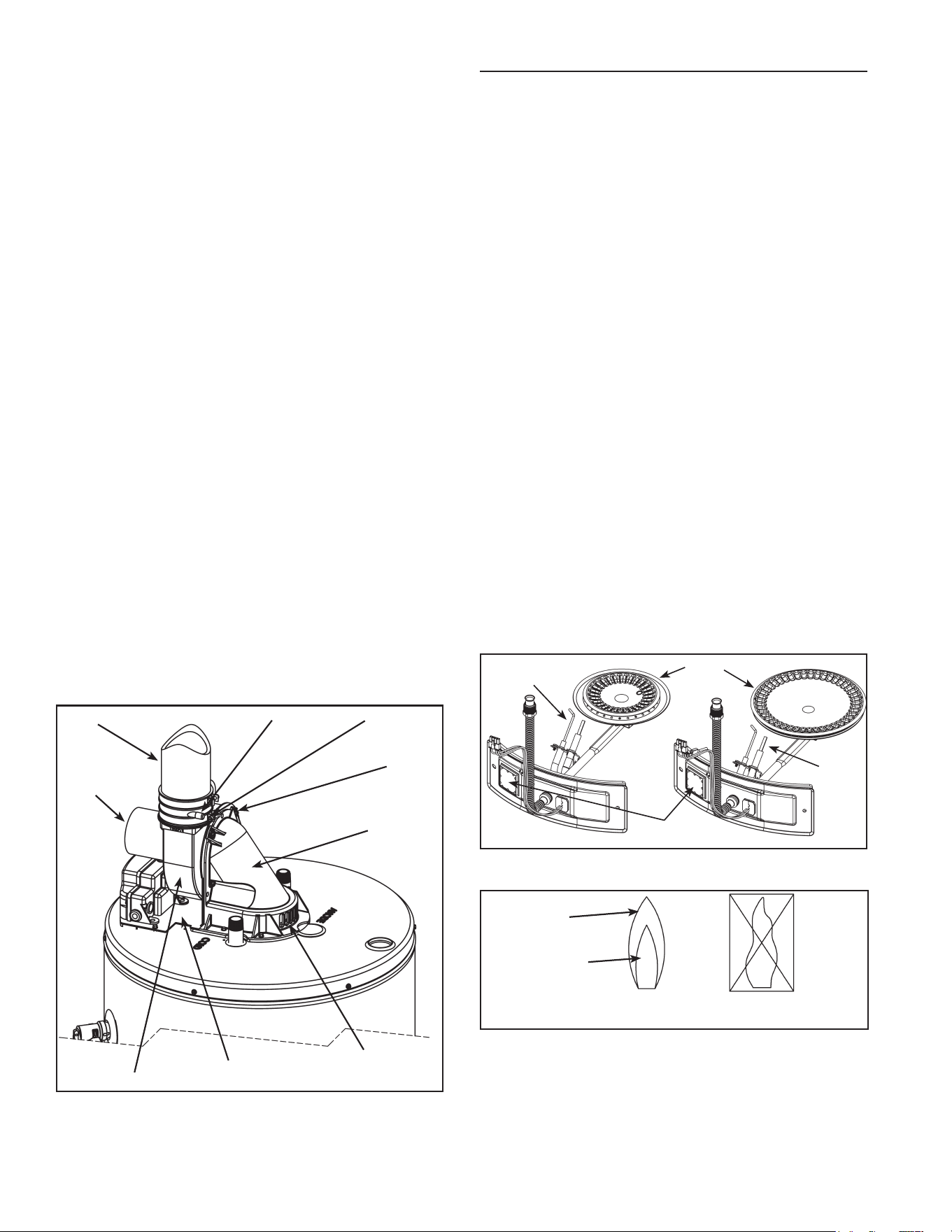
7. Accessingtheblowerwheelthroughtheoutlet,use
the paint brush to brush o the outer edge of the
blowerwheeltodislodgethedirtstuckontheblades
andtheinsideofthehousing.Rotatethewheeluntil
allbladesareclear.Note:Thewheelisabalanced
component.Donotbend,dentordistortthebladesas
thiscanupsetthewheelbalanceandaecttheblower
operation.Vacuumoutthelooseneddirt.
8. Accessingtheinsideoftheblowerwheelthroughthe
rearofthehousing,gentlybrushotheinsideofthe
bladesusingthetoothbrush.Again,takecarenotto
distorttheblades.Rotatethewheeluntilallbladesare
cleanedandvacuumthedebris.Donotremoveany
ofthebalancingchipsattachedtotheblades.
9. Inspectthe uecollector hood(still attached to the
heater)andvacuumoutthedustanddebristhatmay
haveaccumulated.
10. Withallpartscleanedandtheblowerwheelturning
freely, reinstall the blower to the mounting plate
aligningthe(4)studsandpushingtightagainstthe
mountingplate.
11. Reinstallthe(4)11/32”nutsandtightensecurely.All
(4)nutsmustbeinplaceandsecuretosafelyoperate
theblower.
12. Reattachtheventpipingandcouplingtothetopofthe
blower,tightenthebottomgearclampandensurethe
pipingissecure.
13. Withallcomponentscleanandsecure,reconnectthe
electricalpowertotheheater.
14. Reset the thermostat to the desired temperature
setting and turn the gas control switch back to the
“ON”position.Note:Ifthewaterintheheaterishot,
theunitwillwaittooperateuntilthereisaneedfor
morehotwater.
BLOWER
DILUTION
AIRINTAKES
COUPLING
BLOWER
FLUE
COLLECTOR
HOOD
11/32”
NUTS
MOUNTING
PLATE
GEAR
CLAMP
VENT
PIPE
MOTOR
Figure 49.
BURNER OPERATION AND INSPECTION
Flooddamagetoawaterheatermaynotbereadilyvisible
orimmediatelydetectable.However,overaperiodoftime
aoodedwaterheaterwillcreatedangerousconditions
whichcancausedeath,seriousbodilyinjury,orproperty
damage.Contactaqualiedinstallerorserviceagencyto
replaceaoodedwaterheater.Donotattempttorepair
theunit!Itmustbereplaced!
Atleastonceayearavisualinspectionshouldbemadeof
themainburnerandthehotsurfaceigniterassemblyfor
properamecharacteristicsandignitionsequences.This
canbedonebyremovingtheouterdoorandviewingthe
mainburneroperationthroughtheviewportontheinner
door (see Figure 50). The main burner should provide
completecombustionofgas,igniterapidly,givereasonably
quietoperation,andcausenoexcessiveameliftingfrom
theburnerports.Iftheproper ame characteristics are
notevident(seeFigure51),makesurethattheowof
combustionandventilationairisnotblocked.
Youshouldalsocheckforsooting.Sootisnotnormaland
willimpairpropercombustion.Avisualinspectionofthe
mainburnerandhotsurfaceignitershouldalsobedone
atleastonceayear(seeFigure50).
Sootbuild-upindicatesaproblemthatrequirescorrection
before further use. Turn “OFF” gas to water heater by
unpluggingthepowercordandleaveountilrepairsare
made.Failuretocorrectthecauseofthesootingcanresult
inarecausingdeath,seriousinjury,orpropertydamage.
VIEWPORT
MAIN
BURNER
IGNITER
AND FLAME
ROD
IGNITER
AND
FLAME
ROD
Figure 50.
CORRECT FLAME
SOFT BLUE
INCORRECT
FLAMELAZY
YELLOW
BLUE TIPS
LIGHT BLUE INNER
CONES ARE
SATISFACTORY
Figure 51.
45
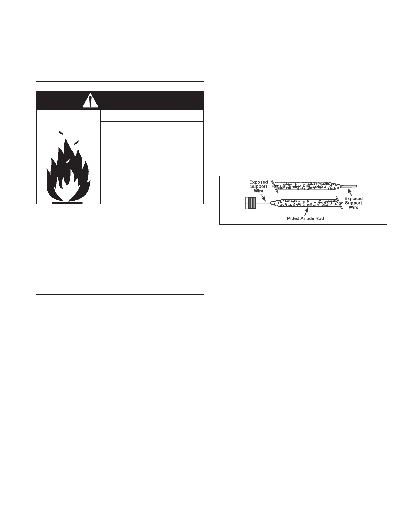
COMBUSTION CHAMBER AND BURNER CLEANING
Intheeventyourburner or burner airopeningsrequire
cleaning,Callyourserviceagencytoremoveandclean
theburnerandcorrecttheproblemthatrequiredtheburner
tobecleaned.
HOUSEKEEPING
• Do not obstruct combustion air
openings at the rear of the water
heater.
• Do not use or store flammable
vapor products such as gaso-
line, solvents or adhesives in the
same room or area near water
heater or other appliance.
• Can cause serious injury or
death.
Fire and Explosion Hazard
DANGER
INSTALLEDINSUITABLEAREA:
To ensure sufficient ventilation and combustion air
supply, proper clearances from the water heater must
be maintained. See “Locating the New Water Heater”
section.Combustiblematerialssuchasclothing,cleaning
materials,orammableliquids,etc.mustnotbeplaced
againstoradjacenttothewaterheaterwhichcancause
are.
ANODE ROD INSPECTION
Each water heater contains at least one anode rod,
whichwillslowlydeplete(duetoelectrolysis)prolonging
thelifeofthewaterheaterbyprotectingtheglass-lined
tankfromcorrosion.Adversewaterquality,hotterwater
temperatures, high hot water usage, hydronic heating
devicesandwatersofteningmethodscanincreasetherate
ofanoderoddepletion.Oncetheanoderodisdepleted,
thetankwillstarttocorrodeeventuallydevelopingaleak.
Certainwaterconditionswillcauseareactionbetweenthe
anoderodandthewater.Themostcommon complaint
associated with the anode rod is a “rotten egg smell”
produced from the presence of hydrogen sulde gas
dissolved in the water. Important: Do not remove this
anode rod permanently as it will void any warranties.
A special anode rod may be available if water odor or
discolorationoccurs.Note:Thisanoderodmayreduce
butnoteliminatewaterodorproblems.Thewatersupply
system may require special ltration equipment from a
waterconditioningcompanytosuccessfullyeliminateall
waterodorproblems.
Articiallysoftened water canbe exceedinglycorrosive
because the process substitutes sodium ions for
magnesiumandcalciumions.Theuseofaexcessively
softwatermaydecreasethelifeofthewaterheatertank.
Theanoderodshouldbeinspectedafteramaximumof
threeyearsandannuallythereafteruntiltheconditionof
theanoderoddictatesitsreplacement.Note:Articially
softened water requires the anode rod to be inspected
annually.
Thefollowingaretypical(butnotall)signsofadepleted
anoderod:
• Themajorityoftheanoderod’sdiameterislessthan
3/8”.
• Signicant sections of the support wire (approx. 1/3
or more of the anode rod’s length) are visible (see
Figure52).
Iftheanoderodshowsignsofeitherorbothitshouldbe
replaced.Note:Whetherre-installingorreplacingthe
anoderod,checkforanyleaksandimmediatelycorrect
iffound.
Figure 52.
ANODE ROD
Important:Useonlyfactoryauthorizedreplacementparts.
If you lack the necessary skills to properly perform the
installation,youshouldnotproceed,butgethelpfroma
qualiedservicetechnician.
• Toolsrequired:
• Ratchetwith1-1/16”Socket
• Pliers
• Teon
®
Tapeoranapprovedpipesealant
Removing Anode Rod:
1. Set the gas control valve/thermostat to its lowest
setting by turning the knob counter-clockwise to
theVACpoint(seeFigure48).Ifthewaterheateris
running,waitforittoshutdown.
2. Turngascontrolswitchtothe“OFF”position.
3. Disconnecttheelectricalpowertothewaterheater
fromthewalloutlet.
4. Shutotheincomingwatersupplytothewaterheater
andopenanearbyhot-waterfaucettodepressurize
thewatertank.
5. Connectahosetothedrainvalveandterminateitto
adequatedrainortotheexteriorofthebuilding.Open
thedrainvalveandallowatleast5gallonsofwater
todrainfromthetank.Closedrainandremovehose.
6. Remove the anode cap on top of the heater and
removejustenoughinsulationsoyoucanaccessto
theanodehead(seeFigure53).Keeptheanodecap
inasafeplaceforreinstallationlater.
7. Remove the anode rod by using a ratchet and a
1-1/16”socketturningcounter-clockwise(seeFigure
53).
46
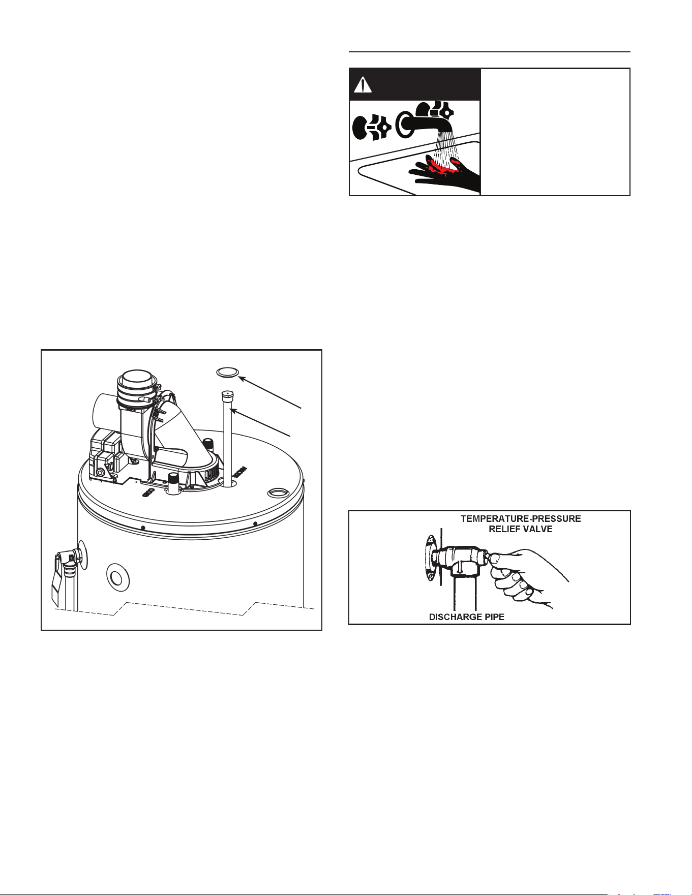
Installing Anode Rod:
1. Use Teon® tape or an approved pipe sealant on
threadsofthenewanoderod.
2. Placetheanoderodinthespud(topofthetank)and
turnclockwiseuntilthethreadsarehandtight.Using
aratchetand1-1/16”sockettightendownwatertight.
3. Openanearbyhot-waterfaucettopurgeairfromthe
waterline.Open the incomingwatersupply and ll
water heater tank completely (Note: To assure the
water heater tank is full, keep the hot-water faucet
openfor3minutesafteraconstantowofwateris
obtained).
4. Turning o the hot-water faucet, check for water
leaksaroundanoderodandimmediatelycorrectany
iffound.
5. Reinstall the insulation and anode cap which were
removedinstep6ofremovalinstructions.
6. Withallcomponentscleanandsecure,reconnectthe
electricpowertotheheater.
7. Reset the thermostat to the desired temperature
setting and turn the gas control switch back to the
“ON”position(seeFigure48).
CAP
ANODE ROD *
* THE ANODE ROD IS COVERED
BY URETHANE FOAM LOCATED
UNDER THE CAP. CHIP AWAY
THE FOAM TO EXPOSE THE
TOP OF THE ANODE ROD
Figure 53.
TEMPERATURE-PRESSURE RELIEF VALVE TEST
• Burn hazard.
• Hot water discharge.
• Keep clear of
temperature-pressure
relief valve discharge.
BURN
HOT
HOT
DANGER
It is recommended that the temperature-pressure relief
valvebecheckedtoensureitisinoperatingconditionat
leastonceayear.
When checking the temperature-pressure relief valve
operation,makesurethat(1)nooneisinfrontoforaround
theoutlet oftheT&Pvalvedischarge line,and (2)that
waterdischargewillnotcauseanypropertydamage,as
water may be extremely hot. Use care when operating
valveasthevalvemaybehot.
To check the relief valve, lift lever at the end of valve
several times (see Figure 54). The valve should seat
properlyandoperatefreely.
Ifaftermanuallyoperatingthevalve,itfailstocompletely
resetandcontinuestoreleasewater,immediatelyclose
thecold-waterinlettothewaterheateranddrainthewater
heater, see “Draining and Flushing” section. Replace
theT&Pvalvewithaproperlyrated/sizednewone,see
“Temperature-Pressure Relief Valve” for instructions on
replacement.
Figure 54.
If the Temperature-Pressure Relief Valve on the water
heaterweepsordischargesperiodically,itmaybedueto
thermalexpansion.
Note: Excessive water pressure is the most common
cause of temperature-pressure relief valve leakage.
Excessivewatersystempressureismostoftencaused
by“thermalexpansion”ina“closedsystem.”See“Closed
WaterSystems”and“ThermalExpansion”sectionsofthis
manual.TheT&Pvalveisnotintendedfortheconstant
reliefofthermalexpansion.
47
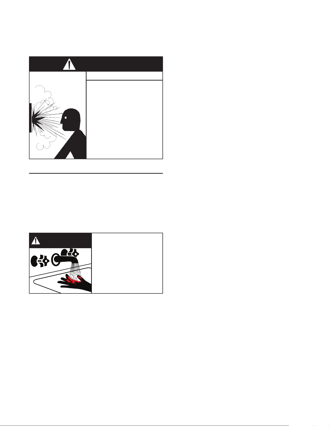
Temperature-pressurereliefvalveleakageduetopressure
buildupinaclosedsystemthatdoesnothaveathermal
expansiontankinstalledisnotcoveredundertheLimited
Warranty.Thermalexpansiontanksmustbeinstalledon
allclosedwatersystems.
• Temperature-pressure relief
valve must comply with ANSI
Z21.22-CSA4.4 and ASME
code.
• Properly sized temperature-
pressure relief valve must be
installed in opening provided.
• Do not plug, block, or cap the
discharge line.
• Failure to follow this warning
can result in excessive tank
pressure, serious injury or
death.
Explosion Hazard
WARNING
DRAINING AND FLUSHING
Periodicdrainingandcleaningofsedimentfromthetank
maybe necessary. It is recommended that the tank be
drainedandushedevery6monthstoremovesediment
whichmaybuildup during operation.The water heater
should be drained if being shut down during freezing
temperatures. See “Typical Installation” section in this
manual for location of the water heater components
describedbelow.
• Burn hazard.
• Hot water discharge.
• Keep hands clear of drain
valve discharge.
BURN
HOT
HOT
DANGER
To drain the water heater storage tank:
1. Turn“OFF”theelectricalsupplytothewaterheater.
2. Turn“OFF”thegassupplyattheMainGasshut-o
Valveifthewaterheaterisgoingtobeshutdownfor
anextendedperiod.
3. CLOSEthecold-waterinletvalvetothewaterheater.
4. OPENanearbyhot-waterfaucetandleaveopento
allowfordraining.
5. Connectahosetothedrainvalveandterminateto
anadequatedrain.
Note:Ifthewaterheaterisgoingtobeshutdownand
drainedforanextendedperiod,thedrainvalveshouldbe
leftopenwithhoseconnectedallowingwatertoterminate
toanadequatedrain.
6. Closethewaterheaterdrainvalvewhenallwaterin
thestoragetankhasdrained.
7. Followinstructions inthe“Filling theWaterHeater”
section.
8. Turn “ON” the gas supply at the main gas shut-o
valve.
9. Follow the lighting instructions on the label or see
“LightingInstruction”torestartthewaterheater.
To ush the water heater storage tank:
1. Turn“OFF”theelectricalsupplytothewaterheater.
2. Ensurethecold-waterinletvalveisopen.
3. Connectahosetothedrainvalveandterminateitto
anadequatedrain.
4. Ensurethedrainhoseissecuredbeforeandduringthe
entireushingprocedure.Flushingisperformedwith
systemwaterpressureappliedtothewaterheater.
5. Openthewaterheaterdrainvalvetoushthestorage
tank.Caution:Waterwillbehot.
6. Flush the water heater storage tank to remove
sedimentandallowthewatertoowuntilitrunsclean.
7. Closethewaterheaterdrainvalvewhenushingis
completed.
8. Removethedrainhose.
9. Ensuretheheaterisfullofwater.
10. Turn“ON”electricalsupplytoplacewaterheaterback
inoperationandfollowthelightinginstructions.
11. Allowthe waterheatertocomplete several heating
cyclestoensureitisoperatingproperly.
Caution:Donotturnonpowertothewaterheaterunless
the tank is full. Open a hot-water faucet and allow the
waterto run untilthe airispurged andthewater ows
uninterruptedfromthefaucet.
Important:Whenoperatingacoldtank,condensationcan
occuranddripontheburner.Thisshouldnotbeconfused
withatankleak.
48
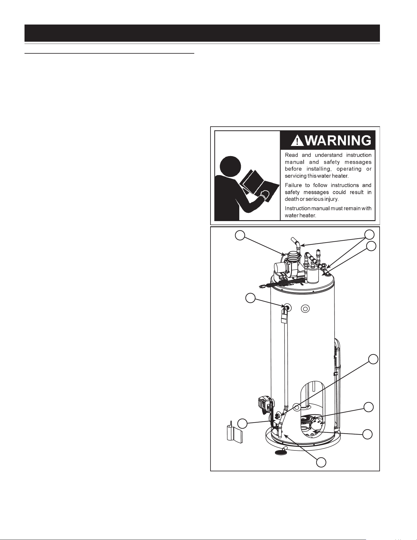
SERVICE
If a condition persists or you are uncertain about the
operationofthewaterheatercontactaserviceagency.
Usethisguidetochecka “leaking” water heater.Many
suspected“leakers”arenotleakingtanks.Oftenthesource
ofthewatercanbefoundandcorrected.
If you are not thoroughly familiar with gas codes, your
water heater and safety practices, contact your gas
supplierorqualiedinstallertocheckthewaterheater.
Ensuretheventingisproperlyattachedandsecured.
Neverusethiswaterheaterunlessitiscompletelylled
withwater.Topreventdamagetothetank,thetankmust
belledwithwater.Watermustowfromthehot-water
faucetbeforeturning“ON”gastothewaterheater.
A. Water at the blower assembly is water vapor which
hascondensedoutofthecombustionproducts.This
iscausedbyaprobleminthevent.Adrainageportis
includedattheventpipeconnection.Contactthegas
utility.
B. *Condensationmaybeseenonpipesinhumidweather
orpipeconnectionsmaybeleaking.
C.*Theanoderodttingmaybeleaking.
D.Small amounts of water from temperature-pressure
reliefvalvemaybeduetothermalexpansionorhigh
waterpressureinyourarea.
E. *Thetemperature-pressurereliefvalvemaybeleaking
atthetanktting.
F. Waterfromadrainvalvemaybeduetothevalvebeing
slightlyopened.
G.*Thedrainvalvemaybeleakingatthetanktting.
H.Combustionproductscontainwatervaporwhichcan
condenseonthecoolersurfacesofthetank.Droplets
formanddripontotheburner.Thisiscommonatthe
timeofstart-up after installationandwhen incoming
wateriscold.
I. Water in the water heater bottom may be from
condensation,looseconnections,or thereliefvalve.
DONOTreplacethewaterheateruntilafullinspection
ofallpossiblewatersourcesismadeandnecessary
correctivestepstaken.
Leakage from other appliances, water lines, or ground
seepageshouldalsobechecked.
* To check where threaded portion enters tank, insert
cottonswabbetweenjacketopeningandtting.Ifcotton
is wet, follow “Draining” instructions in the “Periodic
Maintenance” section and then remove tting. Put
pipedopeorTeontapeonthethreadsandreplace.
Thenfollow“FillingtheWaterHeater”instructionsin
the“InstallingtheNewWaterHeater”section.
A
C
B
H
E
F
G
I
D
Figure 55.
LEAKAGE CHECKPOINTS
49
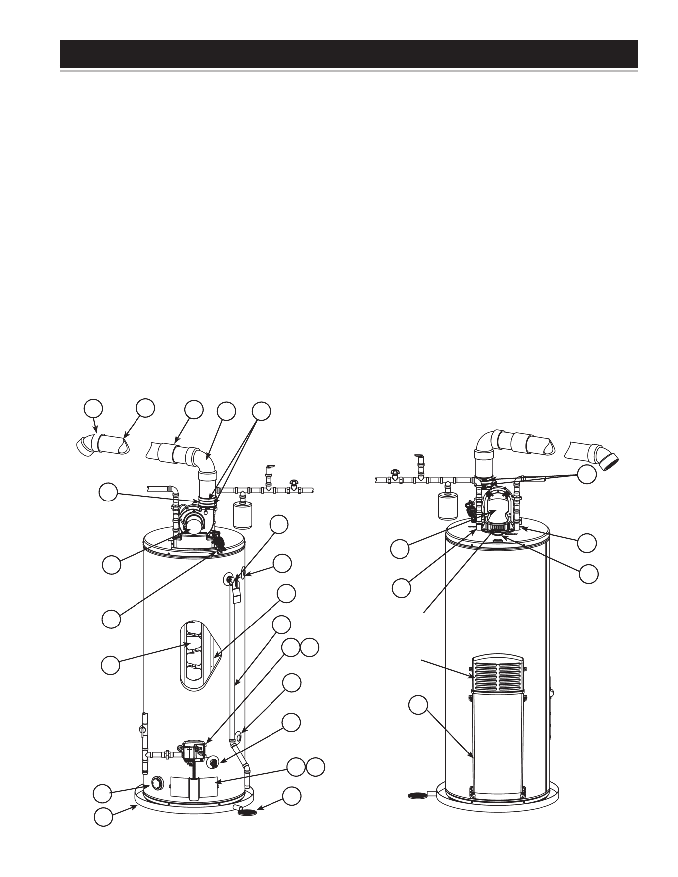
REFERENCE PARTS LISTING
Replacement parts may be ordered
through your plumber or the local
distributor.Whenorderingreplacement
parts, always have the following
informationready:
1. Model,SerialandProductnumber
2. Typeofgas
3. Itemnumber
4. Partsdescription
1. VentTerminationElbowwithRodent
Screen
2. **VentPipe
3. **VentPipeCoupling(ifrequired)
4. **VentPipeElbow(longradius)
5. Blower High Limit Switch (see
Figure61)
6. T&PValve
7. Cold-WaterInletNipple/Diptube
8. BaeAssembly
9. **DischargePipe
10.Gas Control Valve/Thermostat
(Honeywell/Resideo)
11.Gas Valve Electronic Control
ModuleAnd Cover (Honeywell/
Resideo)
12.DrainValve
13.OuterGasDoor
14.Manifold DoorAssembly (behind
outerdoor)(seeFigure58&Figure
59)
15.**FloorDrain
16.**MetalDrainPan
17.Flammable Vapor Sensor (under
cover)(seeFigure60)
18.Combo Heating System Return
Inlet(Optional)
19.AirInletSnorkel
20.Combo Heating System Supply
Outlet(Optional)
21.BlowerwithPowerCord(seealso
Figure61)
22.Air Switch (inside box) (see
Figure61)
23.JunctionBox(seeFigure61)
24.JunctionBoxCover(seeFigure61)
25.AirTubing(seeFigure61)
26.Rubber Coupling (see also
Figure61)
27.GearClamp(seealsoFigure61)
28.FlueCollector
29.Hot-WaterOutletNipple
30.Anode(undercap)
32.Flexible Manifold Tube (see
Figure58&Figure59)
33.Viewport (see Figure 58 &
Figure59)
34.FlameSensorRod(seeFigure58
&Figure59)
35.Gas Orifice (see Figure 58 &
Figure59)
36.SheetMetalBurner(seeFigure58
&Figure59)
37.Gas Manifold (see Figure 58 &
Figure59)
38.Hot-SurfaceIgniter(seeFigure58
&Figure59)
39.Manifold Door Gasket (see
Figure58&Figure59)
40.Manifold Door (see Figure 58 &
Figure59)
41.Two Piece Grommet With Clip
(Figure58&Figure59)
** parts not supplied with the water
heater
FrontView RearView
Figure 56. Figure 57.
1
6
9
10
12
13
16
17
20
18
2
3
4
21
27
21
8
7
14
11
15
26
19
28
29
7
30
Combustion
AirInlets
27
Blower
DilutionAir
Inlets
50
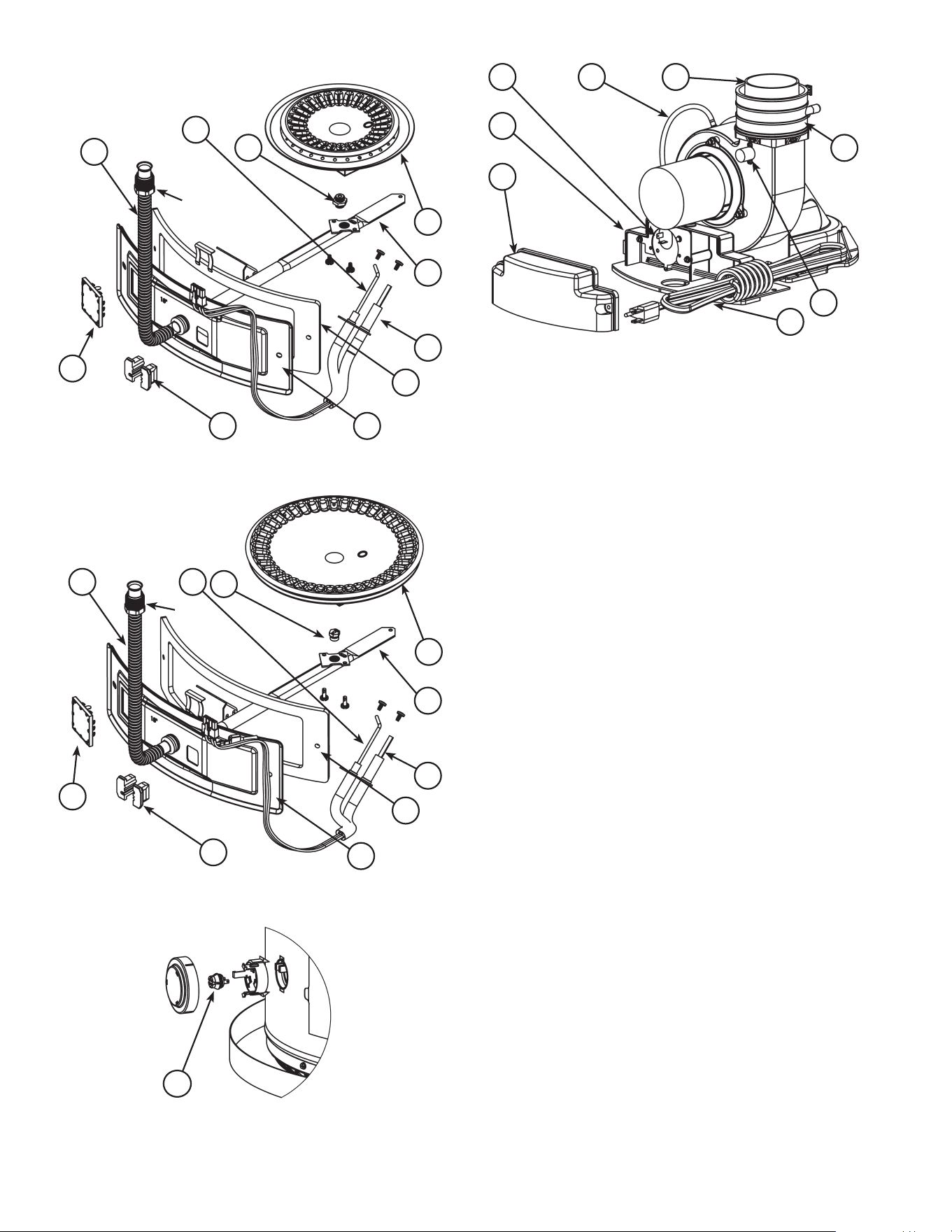
32
34
36
33
38
39
37
35
40
41
NaturalgasandPropanemain
burnerwithigniterassemblyfor
40kto50kBtu/hrmodels
FlareNut**
*
Figure 58.
32 34
36
33
38
39
37
35
40
41
NaturalgasandPropane
mainburnerwithigniter
assemblyfor60kto75k
Btu/hrmodels
Flare
Nut**
*
Figure 59.
17
Figure 60.
25
23
24
22
5
26
27
21
Figure 61.
Notes: * Natural gas models have Right-hand thread,
PropanemodelshaveLeft-handthread.
**ForNaturalgasmodelstheFlareNuthasRight-
handthread.ForPropanemodelstheFlareNut
hasLeft-handthread.
51

Theseguidelinesshouldbeutilizedbyaqualiedserviceagent.
PROBLEM POSSIBLE CAUSE(S) CORRECTIVE ACTION
BURNER FLAME
TOO HIGH
1. Airinletsblocked
2. Insucientsecondaryair
3. Oricetoolarge
1. Unblockinletairopenings
2. Provideventilationtowaterheater
3. Replacewithcorrectorice
FLAME BURNS
AT ORIFICE
1. Lowgaspressure
2. Defectivegascontrolvalve/thermostat
1. Checkwithgasutilitycompany
2. Replacegascontrolvalve/thermostat
INSUFFICIENT
HOT WATER
1. Lowgaspressure
2. Oricetoosmall
3. Thermostatsettoolow
4. Gascontrolerrorcodes
5. Sedimentorlimeintank
6. Waterheatertoosmall
7. Wrongpipingconnections
8. Leakingfaucets
9. Wastedhotwater
10. Longrunsofexposedpiping
11. Hot-waterpipinginoutsidewall
1. Checkwithgasutilitycompany
2. Replacewithcorrectorice(seerating
plate)
3. Turntemperatureknobtohighersetting
4. Refertogascontrolerrorcodes
5. Drain/ush-provide water treatment if
needed
6. Installadequateheater
7. Correctpiping:diptubemustbeincold
inlet
8. Repairfaucets
9. Advisecustomer
10. Insulatepiping
11. Insulatepiping
WATER IS TOO HOT
1. Thermostatistoohigh
2. Defectivegascontrolvalve/thermostat
1. Turntemperatureknobtolowersetting.
Install or adjust Thermostatic Mixing
Valve for each point-of-use (see the
valvemanufacturer’sinstructions)
2. Replacethegascontrolvalve/
thermostat
SLOW HOT WATER
RECOVERY
1. Insucientair/ueblockage
2. Lowgaspressure
3. Oricetoosmall
4. Thermostatsettoolow
5. Heatertoosmall
6. Wrongpipingconnection
7. Wastedhotwater
8. Flueclogged
9. Airinletsblocked
1. Provideventilationtowaterheater.
Checkueway,uebaeandburner
2. Checkwithgasutilitycompany
3. Replacewithcorrectorice(seerating
plate)
4. Turntemperatureknobtohighersetting
5. Installadequateheater
6. Correctpiping-diptubemustbeincold
inlet
7. Advisecustomer
8. Cleanue,locatesourceandcorrect
9. Unblockinletairopenings
DRIP FROM
RELIEF VALVE
1. Pressurebuild-up
2. Heaterstacking
3. Closedwatersystem
4. Improperlyseatedvalve
1. Use a pressure-reducing valve and
reliefvalve
2. Lowerthethermostatsetting
3. Seethermalexpansionsection
4. CheckReliefvalveforproperoperation
(DoNotplugT&Pvalve)
GASCONTROLVALVE/
THERMOSTAT FAILS TO
SHUT OFF
1. Defectivegascontrolvalve/thermostat 1. Replacegascontrolvalve/thermostat
SMELLY WATER
1. Suldesinwatersupply
2. Bacteriainwatersupply
3. Incompatibleanode
1. Chlorinationprocedure
2. Chlorinationprocedure
3. Replace with anode appropriate for
waterconditions
TROUBLESHOOTING GUIDELINES
52

PROBLEM POSSIBLE CAUSE(S) CORRECTIVE ACTION
CONDENSATION
1. Fillingthenewwaterheaterfortherst
time
2. Moisturefromtheproductsofcombustion
3. Waterdrippingfromblowerassembly
4. Undersizedwaterheater
1. Normal operation: the condensation
shoulddisappearafterheaterwarmsup
2. Normal operation: the condensation
shoulddisappearintime
3. Installcondensatehosetodrainporton
therubbercoupling
4. Installadequateheater
COMBUSTION ODORS
1. Airinletsblocked
2. Insucientair
3. Flueclogged
4. Heaterinstalledinaconnedarea
5. Housetootight
1. Unblockinletairopenings
2. Providefreshairventilationtothewater
heater
3. Clean,locatesourceandcorrect
4. Providefreshairventilationtothewater
heater
5. Providefreshairventilationtothewater
heater
SMOKINGANDCARBON
FORMATION
1. Airinletsblocked
2. Insucientair
3. Lowgaspressure
4. Oricetoolarge
5. Flueclogged
6. Defectivegascontrolvalve/thermostat
7. Heaterinstalledinaconnedarea
1. Unblockinletairopenings
2. Provideventilationtowaterheater.
Checkueway,uebaeandburner
3. Checkwithgasutilitycompany
4. Replacewithcorrectorice(seerating
plate)
5. Clean,locatesourceandcorrect
6. Replacegascontrolvalve/thermostat
7. Providefreshairventilation
UNABLE TO LIGHT
THE BURNER
1. Airingasline
2. Pressureswitch
3. Blockedexhaust
4. Wireconnection
5. Defectivegascontrolvalve/thermostat
1. Purgetheairfromgasline
2. Checkthepressureswitch,makesure
thepressureswitchhoseisnotkinked
3. Checkventpipeforblockage
4. Checkwireconnections
5. Replacethegascontrolvalve/
thermostat
SIZZLING,RUMBLING
NOISE
1. Scaleandsediment
2. Condensationdrippingonburner
1. Drain/ush-provide water treatment if
needed
2. Referto“Condensate”section
WATERLEAKAGE
1. Condensation
2. DrippingTemperature&PressureRelief
Valve
3. Drainvalvedripping/leaking
4. TankLeak
1. Referto“Condensate”section
2. Referto“Temperature&PressureRelief
Valve”section
3. Back flush to clean- out sediment,
replaceifnecessary.
4. Check“LeakageCheckpoints”
BLOWER WILL
NOT START
1. Nopowertounit
2. Thermostatsettoolow
3. Defectiveairpressureswitch
4. Defectiveblower
5. Disconnectedorloosewire
6. Controllockedout
1. Pluginpowercord,checkfusesand/or
supplyvoltage
2. Turntemperatureknobtohighersetting
3. Replaceairpressureswitch
4. Replaceblower
5. Repairandreconnectwires
6. Referto“ResettingTheHeaterControl”
–determinecauseoflockout
53
PROBLEM POSSIBLE CAUSE(S) CORRECTIVE ACTION
BLOWER RUNS
CONTINUOUSLY
1. Airpressureswitchnotclosingdueto
insucientdraft–checkfor:
a. Ventpipingblocked
b. Pipinglengthtoolong
c. Clogged/dirtyblower
2. Disconnected,tornorblockedpressure
switchhosefromairpressureswitchto
blowerhousing
3. Defectivepressureswitch
4. Highlimitswitchopenduetoexcessive
venttemperatureordefectiveswitch
1. Determinecauseofinsucient
draft.Checkdraftwithmanometerat
pressureswitch
a. Removeblockage
b. Reduce vent length/increase vent
size
c. Cleanblowerwheel
2. Reconnectorreplacepressureswitch
hose
3. Replacedefectivepressureswitch
4. Determinecauseofoverheatingcheck
for:overring,insucientairsupply,
highambientairtemperature
HOT SURFACE IGNITER
NOT GLOWING
FOLLOWINGWARM-UP
PERIOD
1. 120VAC polarity reversed at 120VAC
outletreceptacle
2. Defectivehotsurfaceigniter
3. Defectivegascontrolvalve/thermostat
1. Reverse polarity at 120VAC outlet
receptacle
2. Replaceigniter
3. Replacegascontrolvalve/thermostat
VENT PIPE TOO HOT
1. Blowerhighlimitswitchfailstoopen-
switchdefective
2. Notenoughdilutionairtomixwithue
gases
3. Airinroomtoohotformixingwithue
gases
4. Wrongburnerorice
1. ReplaceblowerhighlimitswitchReplace
blowerhighlimitswitch
2. Properaircirculationmustbeprovided
forcombustionanddilutionofuetemp
3. Increase ventilation to lower room
temperature
4. Installcorrectorice.
RESETTING THE HEATER CONTROL
• Softlockoutsasdiagnosedbythesystemerrorcodes
requirethegascontroltobereset.
• Toresetthecontrol,slidethe“ON/OFF”switchtothe
“OFF” position. Wait for 10 seconds and move the
switchbacktothe“ON”position.
• Iftheproblemthatcausedthecontroltolockouthas
notbeencorrected,thecontrolwillremainoragaingo
backintolockout.
LOCKOUTS
Soft Lockout
• occurswhenasystemsafetydevicetripstobreakthe
sequenceofoperation.Thecontrolwillretrythesystem
inatimedbasisbutwillnotreinstateoperationuntilthe
failureiscorrected.
Hard Lockout
• occurs when the main controller fails and must be
replaced.
Thegascontrolvalve\thermostatincludesatemperature
limitingECO(EnergyCutO)systemthatwillshutothe
waterheaterifthewatertemperatureistoohigh.
Shouldthewatertemperaturegettoohigh,thediagnostic
statuslightwillindicateacode(4ashes),indicatingan
over-temperatureconditionandthemainburnerwillbe
shuto.Ifahightemperatureconditionoccurs,turnthe
maingassupplyOFFandhavethewaterheaterrepaired
byaqualiedservicetechnician.Contactyourlocaldealer
forserviceinformation.
Note:Shouldanover-temperatureconditionoccur,restart
thewaterheaterandverifytheLEDashsequence.Ifthe
4ashsequenceisobserved,slidethe“ON/OFF”switchto
the“OFF”position.TurnMainGasSupply“OFF”.Replace
the gas control valve\thermostat. See “Removing and
ReplacingtheGasControlValve/Thermostat.”
54
IGNITION STATE AND TIMING
IGNITION STATE TIMING
Pre-purge
5seconds(NGmodels)
15seconds(LPmodels)
HotSurfaceIgniter
(HSI)Warmup
10seconds
IgnitionActivation
Period(IAP)
3.5secondsmaximum
FlameRecognition
Period(FRP)
0.5second
TrialForIgnition IAP+FRP
FlameStabilization
Period
NotApplicable
Inter-purge 30seconds
FlameFailure
ResponseTime
2secondsmax
(@1uAamecurrent)
Post-purge 30seconds
PressureSwitch(PS)
ProvePeriod
2minutes
PressureSwitch(PS)
FaultDelay(failed
open/closed)
2minutes
SoftLockout 20minutes
EnergyCutO
(ECO)LimitLockout
Indenite
FlammableVapor
(FV)SensorLockout
Indenite(see“ResettingThe
HeaterControl”)
SYSTEM STATUS AND ERROR CODES
Themicro-controllerinsidethegascontrolmonitorsthe
ammablevaporsafetyfeatures,theignitionsequence,
temperaturesettingsandoveralloperationoftheheater.
Ifanyoftheseparametersdoesnotoperateproperlythe
controllerwillshutdownthewaterheater,diagnosethe
failureandashanerrorcode.Thetablebelowliststhe
SystemStatusCodesfortheHoneywell/Resideocontrol.
Refer to it and to the “Trouble Shooting Guidelines” to
diagnosetheproblembeforeattemptingcorrectiveaction.
Seealso“FlammableVaporSensor”.
LED Flash Sequence Control Status
Shortash
onceeveryfour
seconds
IDLE(nocallforheat,
nofaultconditions)
“Heartbeat”,
alternatesbright/dim
CallForHeat
(nofaultconditions)
OneFlash,
threesecondpause
LowFlameSignal
(controlcontinuestooperate)
TwoFlash,
threesecondpause
PressureSwitchFailed
Closed
ThreeFlash,
threesecondpause
PressureSwitchFailedOpen
FourFlash,
threesecondpause
ECO(EnergyCutO)Limit
Lockout
thermostattemperaturelimit
wasexceeded.
FiveFlash,
threesecondpause
FlameOutOfSequence
Six-OneFlash,
threesecondpause
SoftLockout
-RetryLimit
-FailedTrialForIgnition
Six-TwoFlash,
threesecondpause
SoftLockout
-RecycleLimit
-PressureSwitch/HighLimit
opened
Six-ThreeFlash,
threesecondpause
SoftLockout
-RecycleLimit
-FlameLost
Six-FourFlash,three
secondpause
SoftLockout
-FlameoutofSequence
Sensed
SevenFlash,
threesecondpause
FlammableVaporSensor
(FVS)Lockout
Eight-OneFlash,
threesecondpause
FlammableVaporSensor
FVSFaultDetected
Eight-TwoFlash,
threesecondpause
TemperatureSensorFault
Detected
Eight-ThreeFlash,
threesecondpause
ElectronicsFaultDetected
Eight-FourFlash,
threesecondpause
ValveFaultDetected
HardwareFault
Lockout
Indenite
55

Thispageintentionallyleftblank.Maybeusedfornotesortorecordotherinstallationinformation.
56

Thispageintentionallyleftblank.Maybeusedfornotesortorecordotherinstallationinformation.
57

Thispageintentionallyleftblank.Maybeusedfornotesortorecordotherinstallationinformation.
58

Thispageintentionallyleftblank.Maybeusedfornotesortorecordotherinstallationinformation.
59

Copyright © 2023, A.O. Smith. All Rights Reserved
Limited Warranty provided by Manufacturer.
