
AC-MV-41
User manual
4K 4x1 Multi-viewer

Page 2 of 37
AC-MV-41 user manual
Contents
Important Safety Instructions ..................................................................................................................................................... 4
Safety Classifications in this Document ................................................................................................................................. 4
Electrical Shock Prevention ..................................................................................................................................................... 4
Weight Injury Prevention ......................................................................................................................................................... 4
Safety Statements .................................................................................................................................................................... 5
Introduction .................................................................................................................................................................................. 6
Features ..................................................................................................................................................................................... 6
Product Overview ......................................................................................................................................................................... 7
Box Contents ............................................................................................................................................................................ 7
Technical Specifications ........................................................................................................................................................... 8
Front and Rear Panel Overview .............................................................................................................................................. 9
Installation .................................................................................................................................................................................. 10
Rack Mounts .......................................................................................................................................................................... 10
Wiring and Connections ........................................................................................................................................................... 10
HDMI Cables .......................................................................................................................................................................... 10
USB Ports ............................................................................................................................................................................... 10
Ethernet/LAN ......................................................................................................................................................................... 10
RS-232 Control ....................................................................................................................................................................... 11
Unbalanced Audio Input Ports ............................................................................................................................................ 12
Balanced Audio Output Ports .............................................................................................................................................. 12
S/PDIF Audio Output Port .................................................................................................................................................... 12
AC Power Connection ........................................................................................................................................................... 12
Initial Setup ................................................................................................................................................................................ 13
Connecting Devices ............................................................................................................................................................... 13
Navigating the Web UI .............................................................................................................................................................. 14
Matrix ...................................................................................................................................................................................... 15
Video Matrix Switching ..................................................................................................................................................... 15
Extracted Audio Matrix Switching ................................................................................................................................... 16
I/O Config ............................................................................................................................................................................... 17
Input Settings ..................................................................................................................................................................... 17
Video Output Settings ...................................................................................................................................................... 18
Multiview Layout Mode Parameter ................................................................................................................................. 19
Extracted Audio Output Settings ..................................................................................................................................... 20
Audio Configuration ....................................................................................................................................................... 21
Multiview Audio Settings ............................................................................................................................................... 22

Page 3 of 37
AC-MV-41 user manual
System .................................................................................................................................................................................... 23
IP Settings .......................................................................................................................................................................... 23
RS232 Settings ................................................................................................................................................................... 24
IP Control ........................................................................................................................................................................... 24
Admin Web Interface ........................................................................................................................................................ 24
User Web Interface ........................................................................................................................................................... 25
Hardware ........................................................................................................................................................................... 25
Cloud Services and Firmware Updates .......................................................................................................................... 26
Diagnostics ............................................................................................................................................................................. 28
HDMI Inputs ....................................................................................................................................................................... 28
HDMI Outputs ................................................................................................................................................................... 29
Console ................................................................................................................................................................................... 30
Command List ................................................................................................................................................................... 31
Troubleshooting ........................................................................................................................................................................ 35
Maintenance .............................................................................................................................................................................. 35
Damage Requiring Service ....................................................................................................................................................... 35
Support ....................................................................................................................................................................................... 35
Warranty ..................................................................................................................................................................................... 36
The Basics ............................................................................................................................................................................... 36
Coverage Details ................................................................................................................................................................... 36
Red Tape ................................................................................................................................................................................. 36
Obtaining an RMA ................................................................................................................................................................. 36
Shipping .................................................................................................................................................................................. 37
Limitation on Liability ........................................................................................................................................................... 37
Exclusive Remedy .................................................................................................................................................................. 37

Page 4 of 37
AC-MV-41 user manual
Important Safety Instructions
Before installing, configuring, and operating the devices and other vendor equipment, AVPro Edge strongly
recommends that each dealer, integrator, installer, and all other necessary personnel access and read all the
required technical documentation, which can be located by visiting AVProEdge.com.
Read and understand all safety instructions, cautions, and warnings in this document and the labels on the
equipment.
Safety Classifications in this Document
Note:
Provides special information for installing, configuring, and operating the devices and
equipment.
Tip:
Provides suggestions and considerations for installing, configuring, and operating the
devices and equipment.
Important:
Provides special information that is critical for installing, configuring, and operating
the devices and equipment.
Cau1on:
Provides special information for avoiding situations that may cause damage to the
devices and equipment.
Warning:
Provides special information for avoiding situations that may cause physical danger to
the installer, end user, etc.
Electrical Shock Prevention
Electric Shock:
Provides special information that is critical for installing, configuring, and operating
the devices and equipment.
Electrical Disconnect:
Provides special information for avoiding situations that may cause damage to the
devices and equipment.
Weight Injury Prevention
Weight Injury:
Installing some of the devices and equipment requires two installers to ensure safe
handling during installation. Failure to use two installers may result in injury.

Page 5 of 37
AC-MV-41 user manual
Safety Statements
Follow all of the safety instructions listed below and apply them accordingly. Additional safety information will
be included where applicable.
1 Read and keep these instructions.
2 Heed and follow all warnings.
3 Clean devices and equipment only with a dry cloth.
4 Do not use the devices near water or expose them to rain and moisture.
5 Do not block any ventilation openings.
6 The devices and their accessories should never be exposed to open flames or excessive heat.
7 Only use attachments and accessories specified by the manufacturer.
8 Install in accordance with the manufacturer’s instructions.
9 Do not install near any heat sources, such as radiators, heat registers, stoves, or other apparatus that
produce heat.
10 Do not defeat the safety purpose of the polarized / grounding-type plug. A polarized plug has two blades
with one wider than the other. A grounding-type plug has two blades and a third grounding prong. The
wide blade, or third prong, are provided for your safety.
11 Protect the power cord from being walked on or pinched, particularly at plugs, convenience receptacles,
and the point where they exit from the devices.
12 Unplug the devices during lightning storms or when unused for long periods of time.
13 To reduce the risk of electrical shock or damage to the devices and their operators, never handle or
touch the devices and power cord with damp or wet hands.
14 To reduce the risk of injury, some of the devices and equipment may require two installers to ensure
safe handling during installation. Failure to use two installers may result in injury.
15 Refer all servicing to qualified service personnel. Servicing is required when the devices have been
damaged in any way, such as the power cord or plug is damaged, liquid has been spilled, objects have
fallen into the devices, the devices have been exposed to rain or moisture, do not operate normally, or
have been dropped.
Page 6 of 37
AC-MV-41 user manual
Introduction
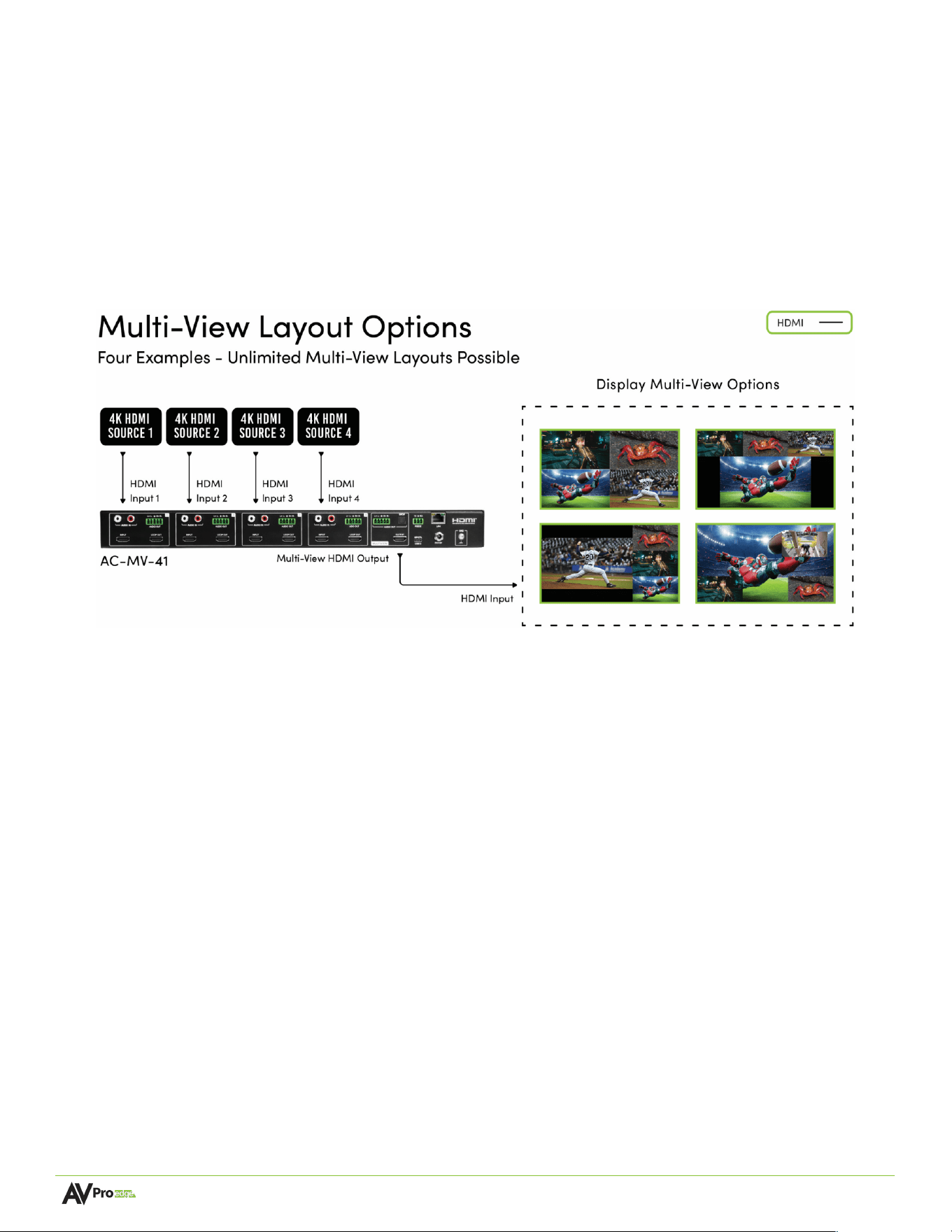
From a single HDMI 2 0 output, the AVPro Edge AC-MV-41 Multi-view video processor simultaneously displays as
many as four separate sources on any size monitor, television, or projector This versatile Multi-viewer/Tiler may be
used stand-alone, enabling four directly connected sources to be viewed as a composite image, video wall style, or
independently full-size, with input switching controlled by most third-party overcontrol systems Recallable presets
may feature all inputs equally in a traditional quad view or customized to highlight one source in a larger window,
with others tiled in an endless variety of patterned layouts.
The diagram below shows the basic application of the AC-MV-41:
Features
• HDMI 2.0 (a/b)
• Preset layouts
• Customizable layouts
• 1 to 4 sources on screen at the same time
• AVPro Edge User Interface
• 18 Gbps Bandwidth Support
• 4K/60 4:4:4 Support
• Full HDR Support (HDR 10- & 12-Bit)

Page 7 of 37
AC-MV-41 user manual
Product Overview
Box Contents
(1x) AC-MV-41 4x1 Multiviewer
(2x) 1U Rack Mounting Brackets
(6x) Screws for Mounting Brackets
(4x) 5-Pin 2 Channel Audio Extraction Cables
(1x) 3-Pin Terminal Block Connector
(1x) 12V Locking Power Supply
Page 8 of 37
AC-MV-41 user manual
Technical Specifications
Video Resolutions Up to 4K60
HDR Formats/Resolutions
420, 422, 444 (10 AND 12 DEEP COLOR)
HDR10, HDR10+, DOLBY VISION, HLG
Color Space
YUV (Component), RGB
(CSC: Rec. 601, Rec. 709, BT2020, DCI, P3
D6500)
Chroma Subsampling 4:4:4, 4:2:2, 4:2:0 Supported
Deep Color Up to 16 bit
Audio Formats Supported HDMI
PCM 2.0 Ch, LPCM 5.1 & 7.1, Dolby Digital,
DTS 5.1, Dolby Digital Plus, Dolby TrueHD,
DTS-HD Master Audio, DTS-X, Dolby Atmos
Analog Input Voltage
0.8 VRMS; 2.3 Vp-p
Audio Formats Supported Extracted (2CH Port)
PCM 2 CH
Analog Output Peak Voltage
1.39 VRMS; 3.94 Vp-p
HDMI In/Out (4k60 4:4:4)
UP TO 50 FEET (USING BULLET TRAIN
HDMI)
HDMI In/Out (W/ AOC Cable) (4k60 4:4:4)
UP TO 130 FEET (USING BULLET TRAIN
AOC)
Bandwidth
18 Gbps (TMDS)
HDCP HDCP 2.3 and Earlier
Control Lan, RS232
Drivers
C4, RTI, ELAN, Crestron, URC (for more -
see Drivers Page)
AVPro WebUI YES
HDMI Type A
LAN RJ45 w/ Web Interface/ Control
Audio (Analog Input) RCA
Audio (Extracted Analog) 5 PIN Terminal Block (Balanced)
RS232 3 Pin Terminal Block
Operating Temperature 23 to 125°F (-5 to 51°C)
Storage Temperature -4 to 140°F (-20 to 60°C)
Humidity Range 5-90% RH (No Condensation)
Power Consumption (Total) 23.04W (12V 1.92A)
Power Supply
Input: AC 100-240V~ 50/60HZ
Output: DC 12V 5A
Dimensions (Unit Only Length/Width/Height)
mm: 225.55 X 439.67 X 44.45
in: 8.88 X 17.31 X 1.75
Dimensions (Packaged Length/Width/Height)
mm: 374.65 X 569.98 X 123.95
in: 14.75 X 22.44 X 4.88
Weight (Unit) 7 Lbs (3.18 Kg)
Weight (Packaged) 9.6 Lbs (4.35Kg)
Power:
Dimensions:
*Specifications subject to change without notice. Mass & dimensions are approximate
Video:
Audio:
Distance:
Other:
Ports:
Environmental:
Control:
Page 9 of 37
AC-MV-41 user manual
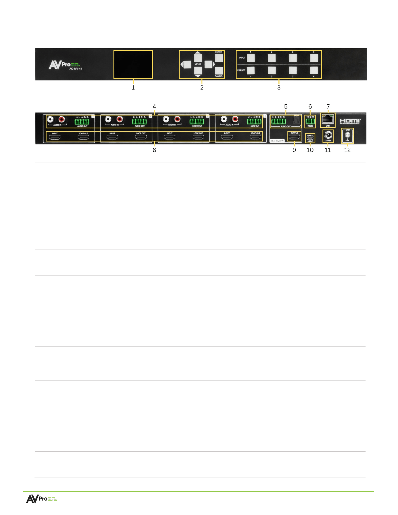
Front and Rear Panel Overview
Front Panel
Rear Panel
1
Front Panel Display
• Front panel display for settings and status
• Up, Down, Menu and Back buttons for navigation
• IP settings and EDID can be changed from front panel
2
Front Panel buttons
• Push-button controls (Up, Down, Left, Right, Enter, Cancel)
• Use buttons to navigate the front panel display menu
3
Input & Multiview Preset Select
buttons
• Input buttons 1 to 4
• Preset buttons 1 to 4
4
Unbalanced Audio Input (1-4)
Balanced Audio Output (1-4)
• (4x) L/R Stereo Phono (unbalanced)
• (4x) Balanced stereo output 5-pin Euroblock connector ports
5
Balanced Audio Output (5)
SPDIF (5)
• Balanced stereo output 5-pin Euroblock connector port
• Digital Optical (S/PDIF) audio output port
6
RS232
• 3-pin Euroblock connector port
7
LAN
• 8-pin RJ45 female connector
• Connect to the LAN, router, or third-party control system
8
HDMI INPUT (1-4)
• (8x) 19-pin HDMI Type-A female connector port
• HDMI source signal input connections (1-4)
• HDMI Loop Outs (1-4)
9
HDMI OUTPUT
• 19-pin HDMI Type-A female connector port
• HDMI signal output to display connection
10
ISP / CTL USB TYPE-C
• Proprietary service port for AVPro Edge technical assistance
11
Power In
• Barrel Connector
• 12 VDC / 5 A power unit
12
Ground
• Ground screw
• Connect the provided wire to Earth ground
Page 10 of 37
AC-MV-41 user manual
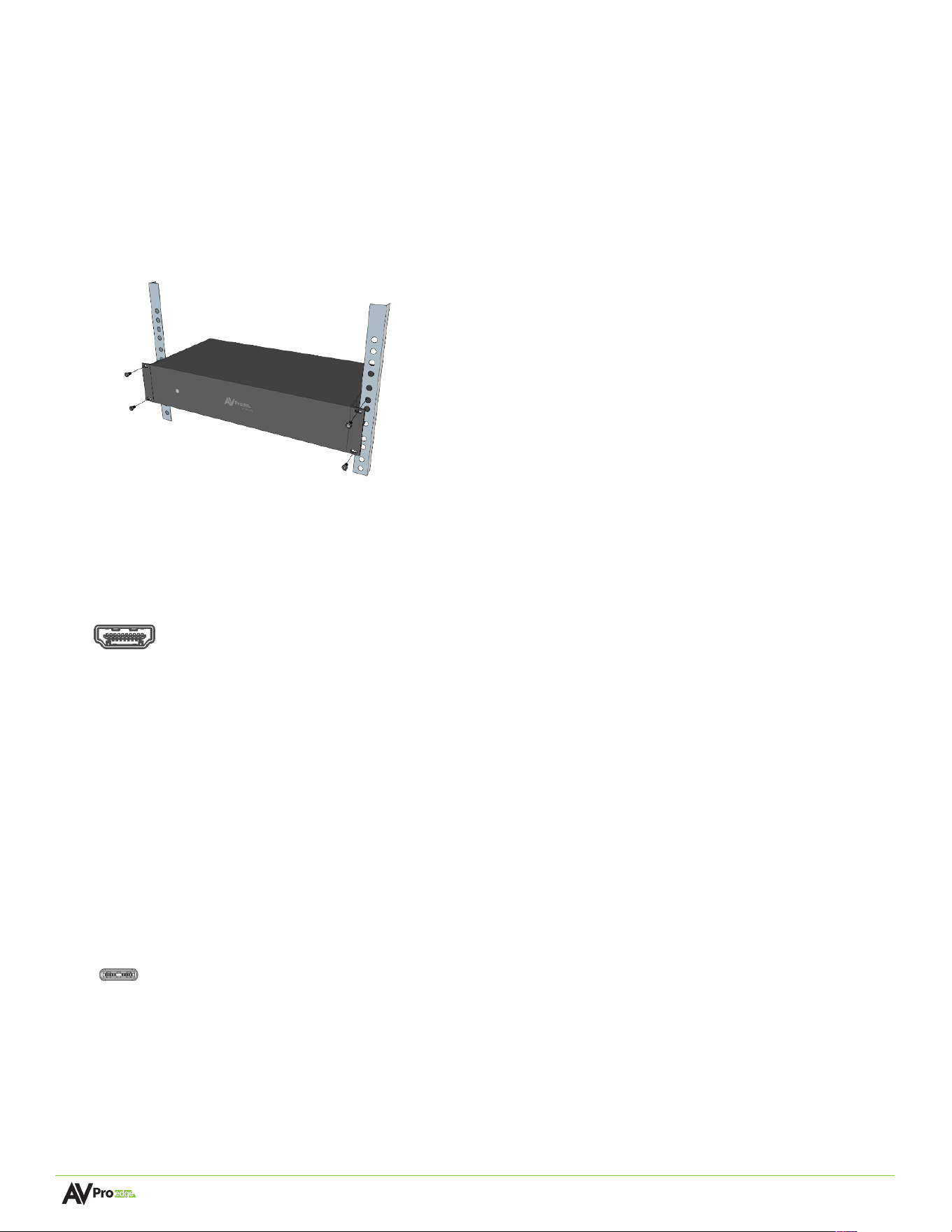
Installation
Rack Mounts
The AC-MV-41 can be mounted in a 1U rack-style enclosure and is compatible with all standard 19-inch rack
mounts. The (2x) mounting brackets are included with the purchase of a unit.
1 Align the holes on the mounting brackets with the holes on both sides of the rack.
2 Attach the mounting brackets to the rack with rack screws (not included).
Wiring and Connections
HDMI Cables
The AC-MV-41 uses the standard 19-pin HDMI female connector ports for the inputs and outputs.
Some important things to consider when planning or installing this device:
• Ensure all HDMI cables and devices can support the signal being sent. For most 4K and below use cases,
a High-Speed HDMI cable with Ethernet rated for 18Gbps will be more than sufficient to satisfy signal
transport if every device in the system can handle the signal.
• Ensure your HDMI cable is the correct length. The current HDMI specification calls for cables to be
between 2 to 10 meters (6.6 to 33 feet) for 4K and below signals. Smaller wire cables may be unable to
transmit higher bandwidth signals.
USB Ports
The device also has one USB Type C port and is only a servicing port intended for AVPro Edge technical support
in the event of troubleshooting and testing.
Ethernet/LAN
The NETWORK/LAN port located on the rear panel is used to communicate with the AC-MV-41 via a LAN, router,
or third-party control system processor and uses a standard RJ45 connector plug.
Type
C
Page 11 of 37
AC-MV-41 user manual
The recommended termination is based on the TIA/EIA T568A or T568B standards for the wiring of the twisted
pair cables. For TCP/IP control, commands use Telnet port 23.
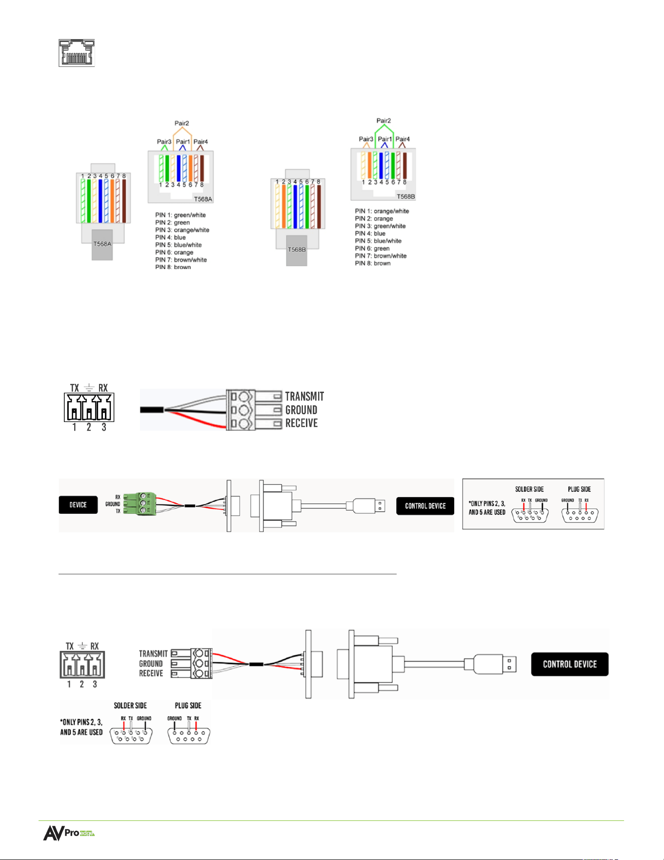
RS-232 Control
The RS-232 control port located on the rear panel is used to communicate with the AC-MV-41 via a computer or
third-party control system.
Serial control connections are made using the provided 3-pin terminal block connector. The wire slips into the
hole and locks with a screw located at the top of the connector.
Wiring for this port uses a 3-pin terminal block connector to DB9, where only pins 2, 3, and 5 are used. If the
control devices do not have a DB9 port, a USB to DB9 adapter may be required.
For RS-232 control, use a null modem serial cable adapter and set the serial communications to:
Baud: 57600, no parity, 8 data bits, 1 stop bit, with no handshaking.
Add a carriage return (Enter key) after each command when using direct commands. The unified command list
(ASCII) can be located here.
T568A T568B
Page 12 of 37
AC-MV-41 user manual
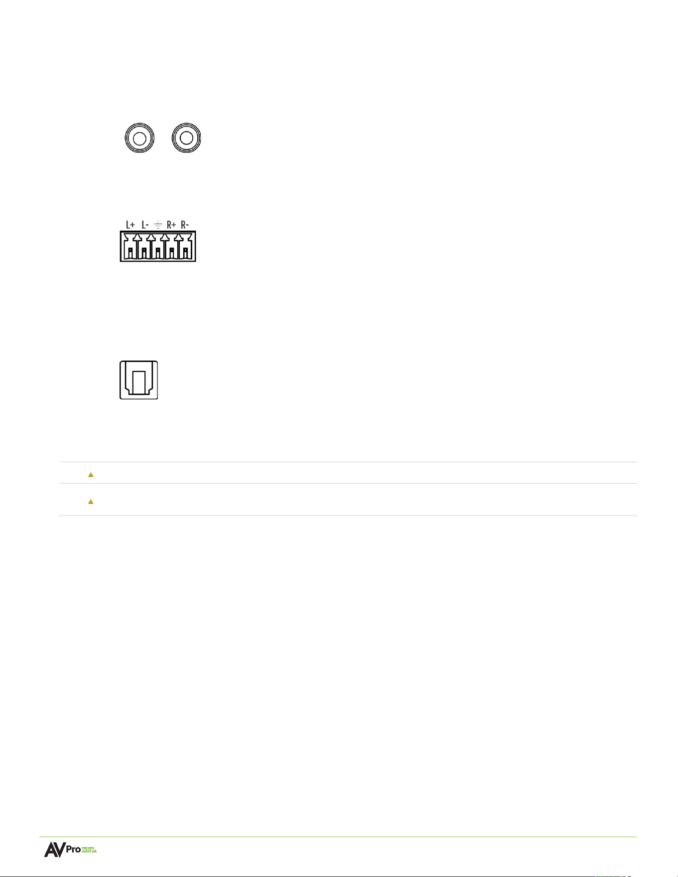
Unbalanced Audio Input Ports
The AC-MV-41 has four Unbalanced L/R Analog audio input ports.
Balanced Audio Output Ports
The AC-MV-41 has five 5-pin terminal block balanced audio output port.
5-pin terminal block pin-out
S/PDIF Audio Output Port
The AC-MV-41 has one S/PDIF audio output port on the unit's rear panel. This port can output multi-
channel audio signals to receivers for surround sound or multi-zone audio systems.
S/PDIF Audio
AC Power Connection
Electric Shock:
Use a surge-protected circuit for all components and power supplies.
Electrical Disconnect:
The power source outlet and power supply input sockets should be easily accessible
to disconnect power in the event of an electrical hazard or malfunction.
Page 13 of 37
AC-MV-41 user manual
Initial Setup
Make physical connections to the input and output devices using the following steps below. For the initial setup, it is
recommended to connect the AC-MV-41 to a LAN (Local Area Network) using a control PC on the same network
once all the physical connections are made followed by accessing the Web UI.
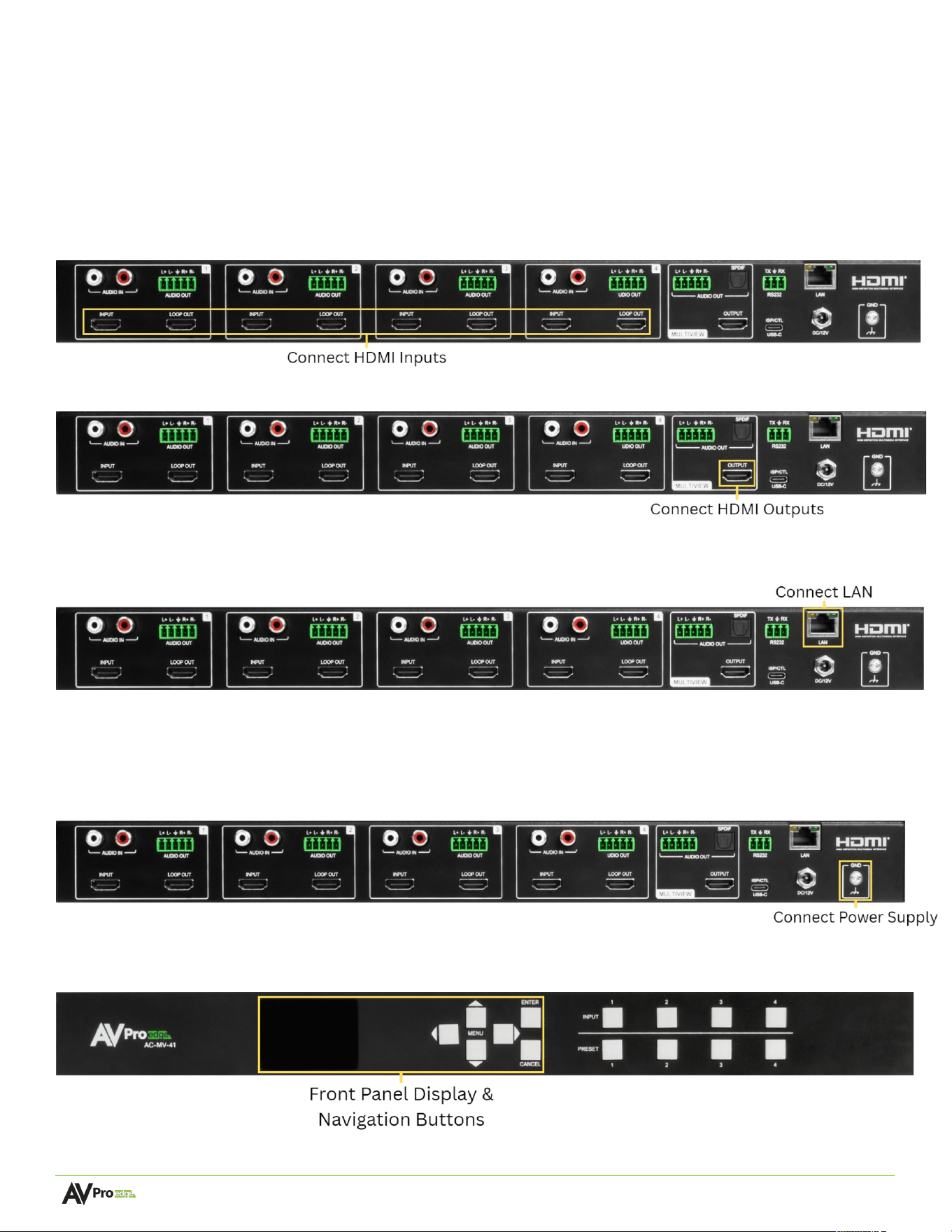
Connecting Devices
1 Connect the HDMI input source(s) to the HDMI INPUT connector on the rear of the AC-MV-41.
2 Connect the HDMI displays/devices to the HDMI OUTPUT(s) on the rear of the AC-MV-41.
3 Connect the video wall processor to the LAN or directly to a PC using an RJ45 cable on the ETHERNET
port on the rear of the AC-MV-41.
4 Power on the source(s) connected to the HDMI INPUT port.
5 Power on the sink(s) connected to the HDMI OUTPUT port(s).
6 Connect the 12V power supply to the POWER input port on the rear of the AC-MV-41, then plug the
power supply into a suitable power source.
7 To check the current IP settings, use the front panel display and buttons to navigate to the menu option
labeled NET. Press MENU, DOWN, and then MENU for IP settings.
Page 14 of 37
AC-MV-41 user manual
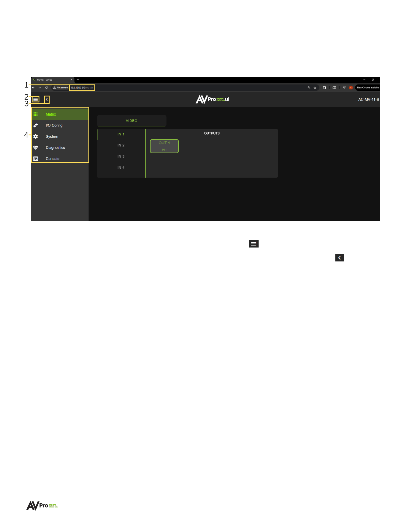
Navigating the Web UI
The AC-MV-41 features the built-in User Interface (UI) that can be accessed through a web browser for configuration
and control. Different tools and settings can be selected from the tab pages located on the navigation menu column
on the left side of the screen.
1 Enter the unit’s IP address into a web browser, such as Chrome or Edge, to access the Web UI.
2 To hide the navigation menu, select the hamburger menu icon .
3 To hide the navigation menu text and show only the menu icons, select the left arrow icon .
4 To navigate through the different pages, select the individual tab pages from the navigation menu. This
will highlight the tab page in green to indicate the currently selected page.
Page 15 of 37
AC-MV-41 user manual
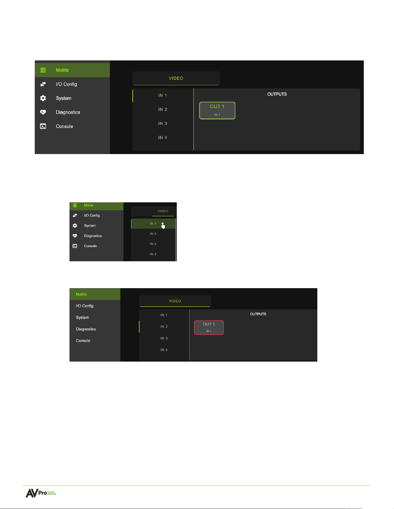
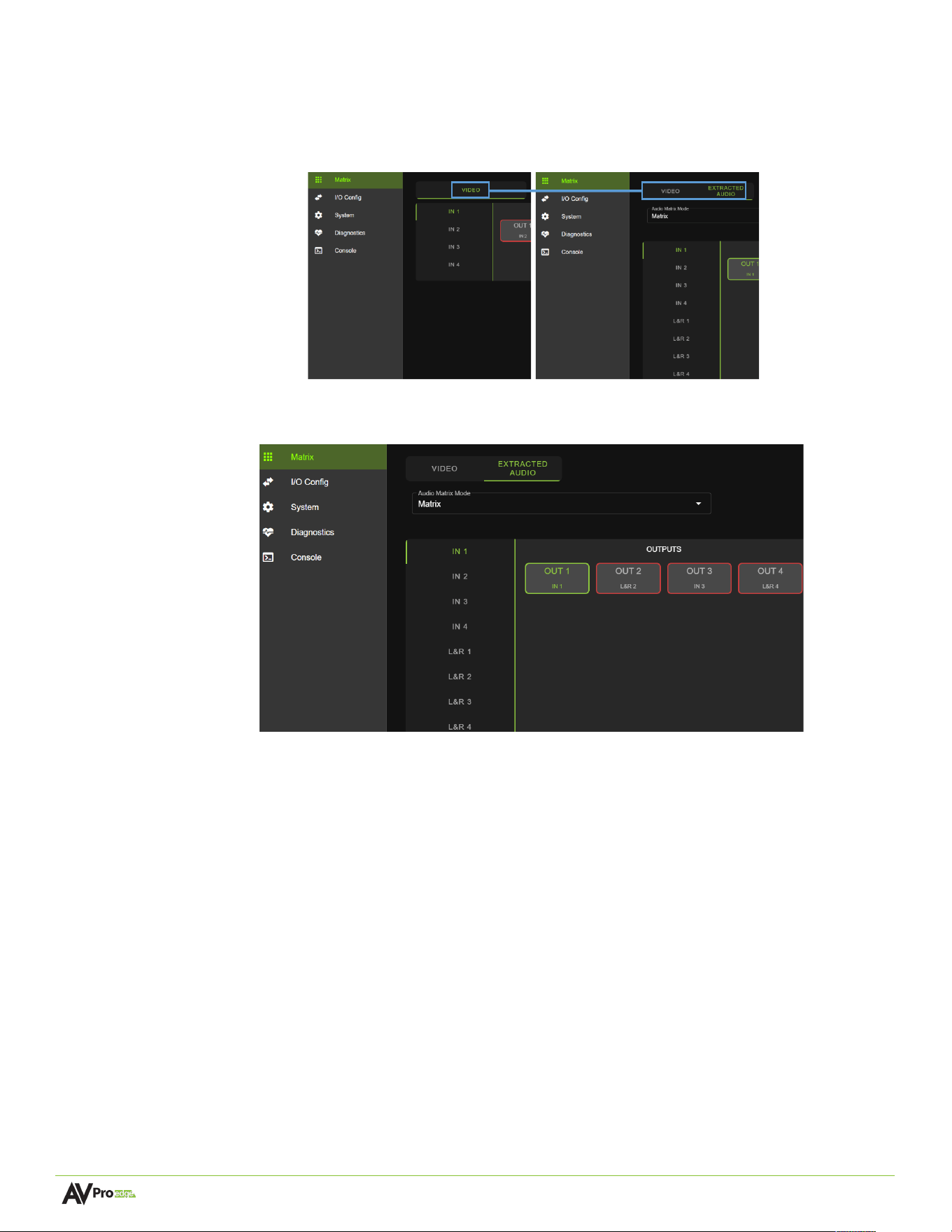
Matrix
The Matrix page layout consists of the Video Inputs column on the left and the Outputs grid on the right. Each
Input and Output can be individually selected to route the input’s audio signals to the output(s).
Video Matrix Switching
1 From the Inputs column, select the desired input. This will highlight the input with a green text to
indicate the selection was made.
2 From the Outputs grid, select the desired output(s) to route the selected input to. This will highlight
the output(s) with a green border to indicate the selection was made.
3 The selected input’s video signals are now routed to the selected output(s).
Page 16 of 37
AC-MV-41 user manual
Extracted Audio Matrix Switching
This menu becomes available when the Audio Mode settings are configured for Matrix.
1 From the Inputs column, select the desired input. This will highlight the input with a green text to
indicate the selection was made.
2 From the Outputs grid, select the desired output(s) to route the selected input to. This will highlight
the output(s) with a green border to indicate the selection was made.
3 The selected input’s audio signals are now routed to the selected output(s).
Page 17 of 37
AC-MV-41 user manual
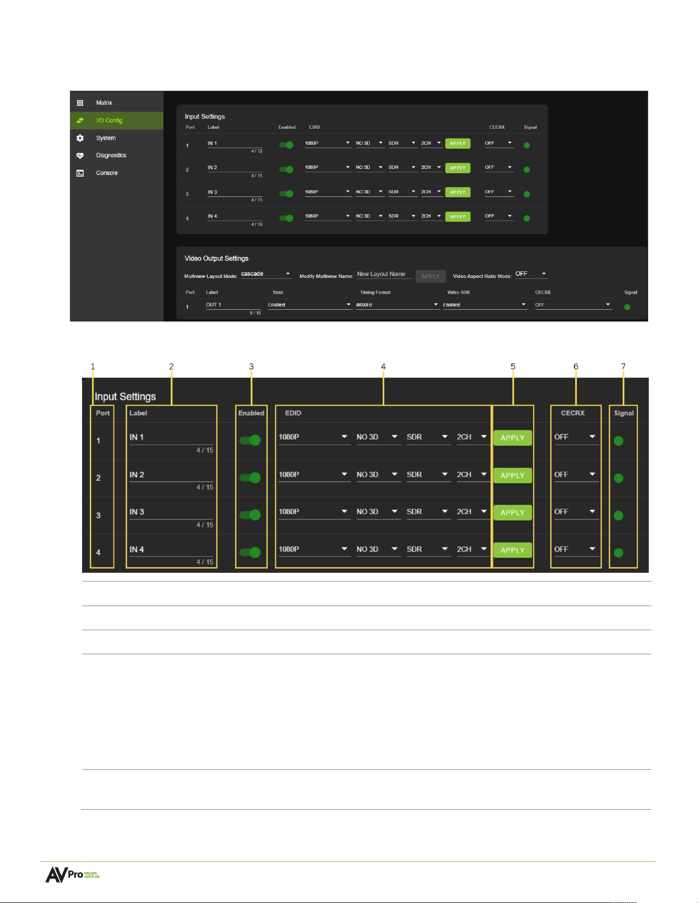
I/O Config
The Config tab page features tools and settings for configuring HDMI inputs and outputs.
Input Se<ngs
1
Port
Shows the HDMI input port number.
2
Label
Select the text field to enter in a custom name for the input. (
Limit of 15 characters
)
3
Enabled
Use the toggle to enable or disable the HDMI input.
4
EDID
Select the EDID from the drop-down menu. The first drop-down configures the
resolution and refresh rate. The second drop-down configures the Dynamic range, with
options for HDR or SDR. The third drop-down configures the audio channels with
options for 2CH, 6CH and 8CH.
NOTE:
Selecting USER1, USER2 or USER3 EDID, the drop-down menus will update,
allowing the user to choose a HDMI Out to copy EDID values from. Select one of the
four HDMI Outs and click the COPY button to apply (this replaces the APPLY button).
5
APPLY
This button applies the settings to the HDMI Input.
NOTE:
This button will change to COPY if the user selects USER1, USER2 or USER3.
Page 18 of 37
AC-MV-41 user manual
6
CECRX
Use the dropdowns to enable or disable CEC Hex data received from the input source.
NOTE:
Due to the hardware changes, these settings are only available on the
AC-MV-41-B
7
Signal
Shows the status of the HDMI Input. Green means the HDMI input is detected, red
means that the HDMI connection or device is not detected.
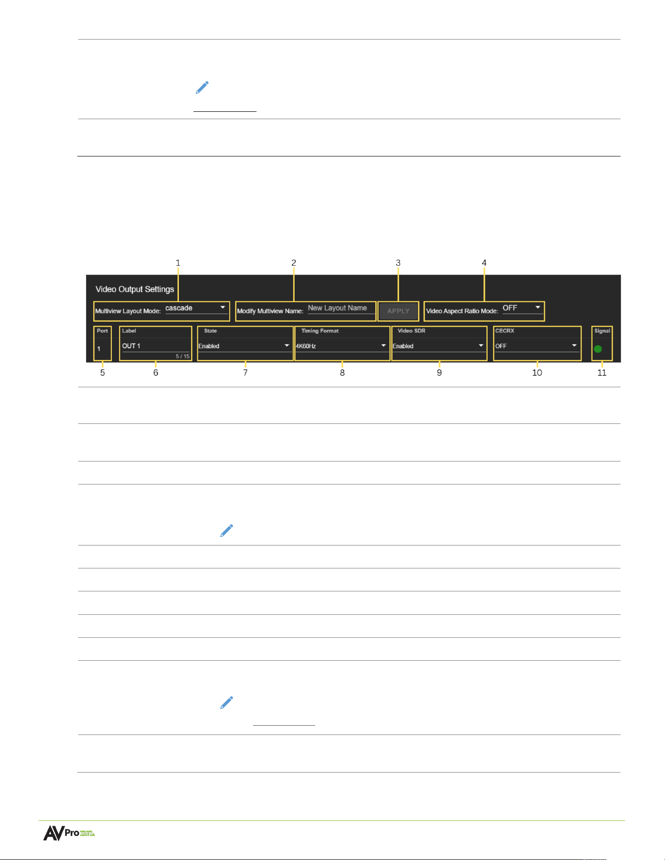
Video Output Se<ngs
1
Multiview Layout
Mode
Use dropdown to select the active Multiview layout preset
2
Modify Multiview
Name
Select the text field to enter in a custom name for the selected Multiview Layout
Mode.
3
APPLY
This button applies the custom Multiview layout name.
4
Video Aspect
Ratio Mode
Use the drop-down to select the output aspect ratio mode.
NOTE: Multiview/ PIP mode needs to be set to off.
5
Port
Shows the HDMI output port number.
6
Label
Select the text field to enter in a custom name for the output.
(
Limit of 15 characters
)
7
State
Use the drop-down to enable or disable the HDMI output.
8
Timing Format
Use the drop-down to select the HDMI output
9
Video SDR
Use the drop-down to enable or disable force SDR mode on all outputs.
10
CECRX
Use the drop-down to enable or disable CEC Hex data received from the output
sink.
NOTE: Due to the hardware changes, these settings are only available
on the AC-MV-41-B
11
Signal
Shows the status of the HDMI Output. Green means the HDMI output is detected,
red means that the HDMI output connection or device is not detected.
Page 19 of 37
AC-MV-41 user manual
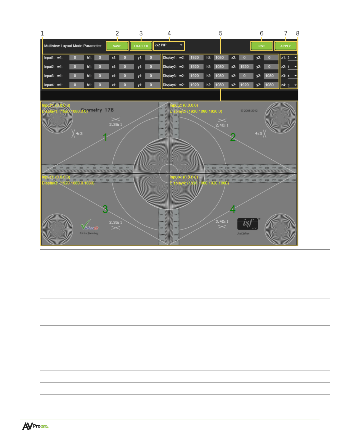
Mul@view Layout Mode Parameter
1
Input
Cropping
Parameters
Enter the Horizontal and Vertical values or use the Up/Down arrows in the dialog boxes to
adjust the image displayed from an HDMI input and to crop the image to the desired
horizontal and vertical values. To apply these settings, click the SET button.
2
Save
Saves a Config file of the active Multiview layout preset selected in Multiview Layout
Mode Parameters.
3
Load
Loads a saved preset config file to selected output. When the selected preset isn’t the
active Multiview layout, the config file will be loaded to the preset but will need to be
applied after switching to the intended preset.
4
Multiview
Layout
Selects which preset slot the layout config file is loaded to.
5
Multiview
Parameters
Can be adjusted by clicking and dragging the intended panel in the Multiview preview, for
more precise adjustments the w2, h2, x2, y2 coordinates can be changed using the up and
down arrow keys.
6
RST
Resets the selected Multiview Layout preset under to the default video coordinates.
7
APPLY
Applies the Multiview Layout Mode Parameters.
8
Multiview
Tile Priority
Use the drop-down to select the Multiview tile priority order.
Page 20 of 37
AC-MV-41 user manual
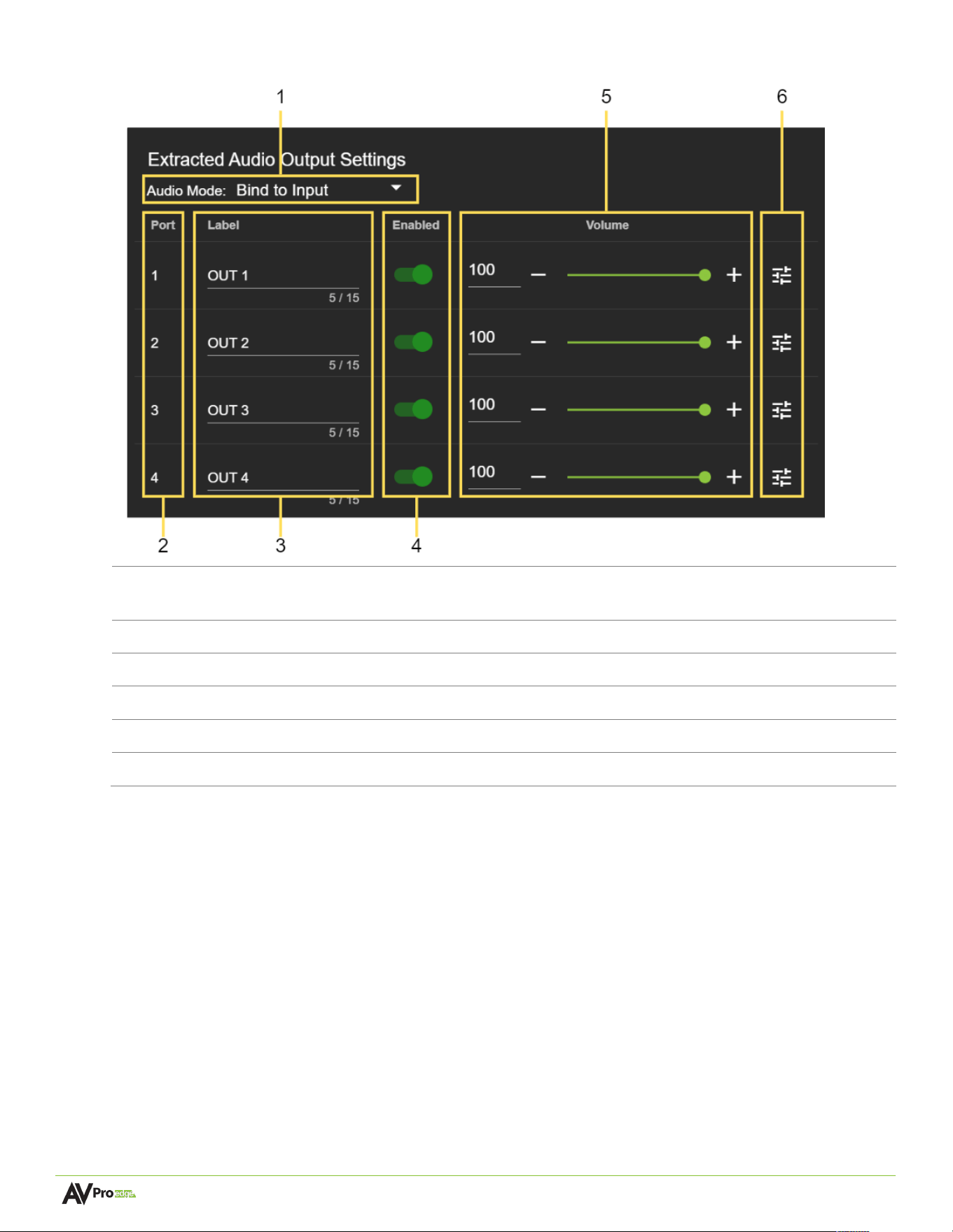
Extracted Audio Output Se<ngs
1
Audio
Mode
Dropdown menu containing the audio binding settings that can be applied to change the
extracted audio routing.
2
Port
Shows the audio output port number.
3
Label
Select the text field to enter in a custom name for the output.
(
Limit of 15 characters
)
4
Enabled
Select the toggle switch to enable or disable the audio output.
5
Volume
Adjust the volume by using the slider bar or entering a value (0~100) in the text field.
6
EQ
Select to view the output
’
s
Audio Configuration
settings.
Page 21 of 37
AC-MV-41 user manual
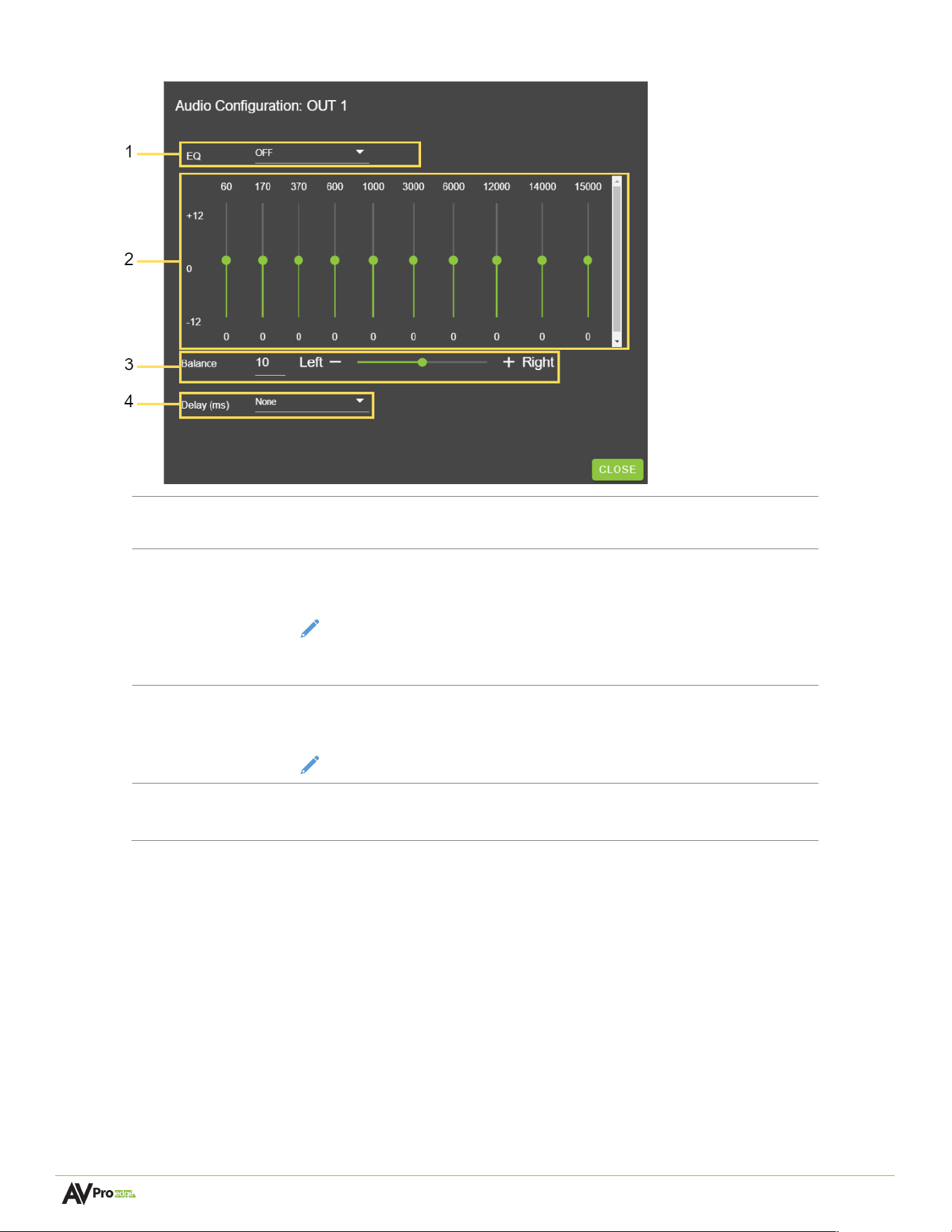
Audio Configura1on
1
EQ
Dropdown menu containing a list of several preset equalizer settings that
can be applied to change the frequency response of the audio output.
2
Frequency
Graphic equalizer showing the individual frequency bands of the output’s
audio.
NOTE:
This graphic equalizer is only intended to be used as a visual
reference of the individual audio frequency gains. Manual
adjustments cannot be made to it.
3
Balance
Adjust the Left and Right volume by using the slider bar or entering a
value (-10 to +10) in the text field.
NOTE:
-10 is balanced left, 0 is balanced, and +10 is balanced right.
4
Delay
(
ms
)
Dropdown menu containing a list of several values that can be applied to
change the delay duration of the audio output
Page 22 of 37
AC-MV-41 user manual
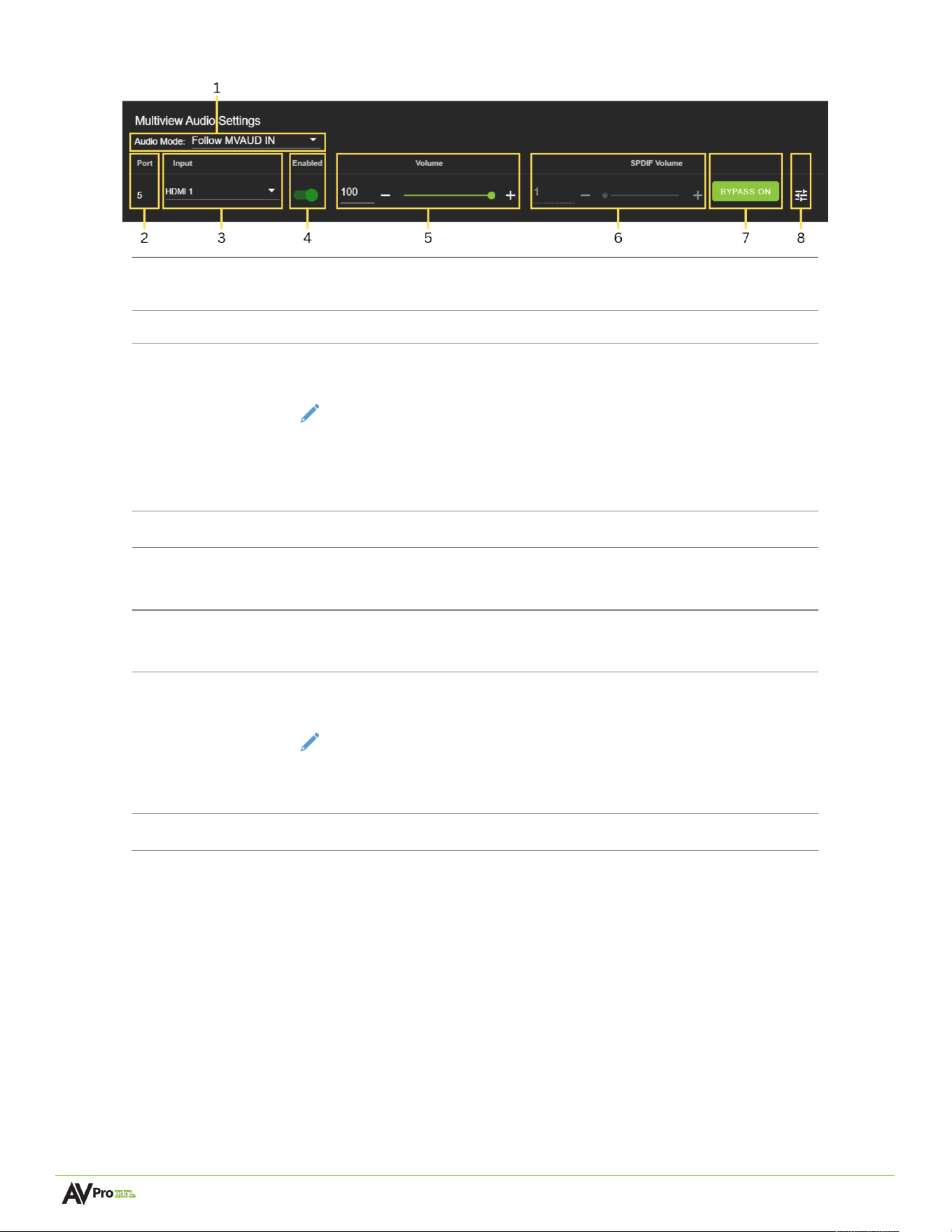
Mul1view Audio SeLngs
1
Audio Mode
Dropdown menu containing the audio binding settings that can be
applied to change the Multiview audio routing.
2
Port
Shows the audio output port number.
3
Input
Use the dropdown to select the Multiview Audio input source.
NOTE:
Switching the Multiview Output (AUDIO OUT 5) between
HDMI (IN 1-4) and Analog (IN 5-8) will cause a momentary video
dropout. However, video will remain stable when switching the Audio
Matrix Outputs (AUDIO OUT 1-4).
4
Enabled
Select the toggle switch to enable or disable the audio output.
5
Volume
Adjust the volume by using the slider bar or entering a value (0~100)
in the text field.
6
SPDIF Volume
Adjust the SPDIF volume by using the slider bar or entering a value
(0~100) in the text fi eld.
7
Bypass
Select to enable and disable the SPDIF Volume control.
NOTE:
Due to the hardware design, if the SPDIF output volume
control is enabled, the balanced audio output volume will change
accordingly.
8
EQ
Select to view the output’s Audio Configuration settings.
Page 23 of 37
AC-MV-41 user manual
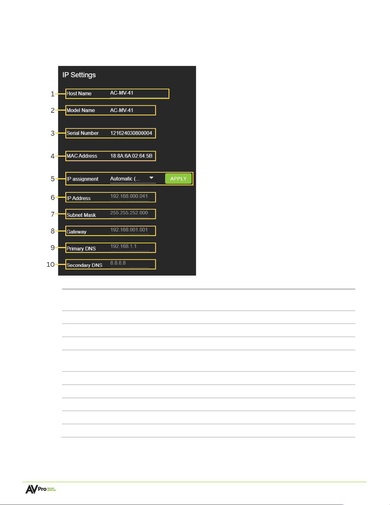
These will be assigned by a DHCP reservation
from the router when the IP Assignment is set to
Automatic, or they can be manually entered in
when the IP Assignment is set to Manual.
Select the Apply button when manually entering
in the IP Assignment, IP Address, Subnet Mask,
Gateway, Primary DNS, and Secondary DNS for
changes to take effect.
System
IP Se<ngs
1
Host Name
Select the text field to enter in a custom name for the unit.
The default shows the unit’s model number.
2
Model Name
Shows the unit
’
s AVPro Edge model number.
3
Serial Number
Shows the unit
’
s unique serial number.
4
MAC Address
Shows the unit
’
s unique MAC address.
5
IP Assignment
Select the dropdown menu to set the unit’s IP mode to
DHCP
(default) or
Manual
(
Static IP
), then select the
Apply
button.
6
IP Address
Shows the unit
’
s IP address.
7
Subnet Mask
Shows the unit
’
s subnet mask.
8
Gateway
Shows the unit
’
s default gateway.
9
Primary DNS
Shows the unit
’
s primary domain name server.
10
Secondary DNS
Shows the unit
’
s secondary domain name server.
Page 24 of 37
AC-MV-41 user manual
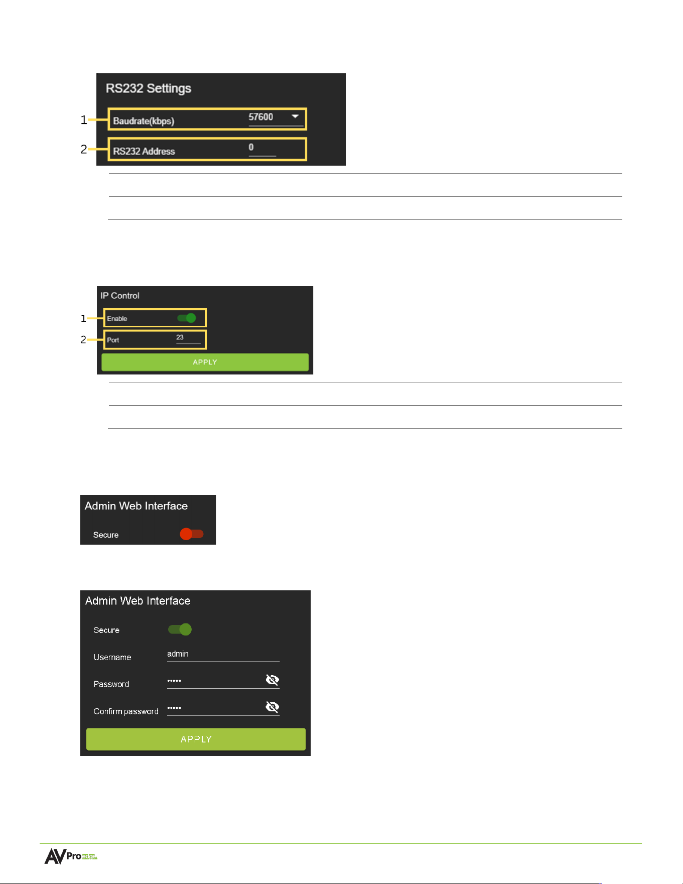
RS232 Se<ngs
1
Baudrate
(
kbps
)
Select the drop-down to set the system Baud Rate. Default is 57600
2
RS232 Address
Select the text field to set the system Address. Default is 00
IP Control
1
Enable
Select the toggle switch to enable or disable IP/TCP control.
2
Port
Select the text field to set the Telnet port. Default is Telnet port 23.
Admin Web Interface
Select the Secure toggle switch to enable (green) or disable (red). When enabled, the username and
password can be changed.
With the Admin Web Interface enabled, the only menu that will be accessible on the Web UI will be the
Matrix tab page. The rest of the settings will require the Admin login.
Default username: admin
Default password: admin
Page 25 of 37
AC-MV-41 user manual
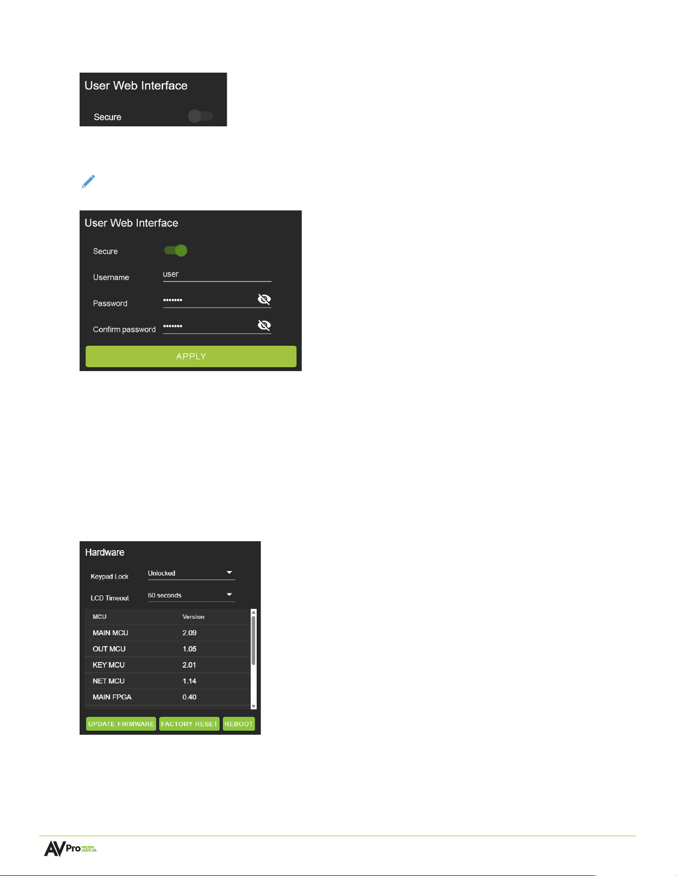
User Web Interface
Select the Secure toggle switch to enable (green) or disable (grey). When enabled, the username and
password can be changed.
NOTE:
The
Admin Web Interface
must first be enabled before this setting can be changed.
With the Admin and User Web Interfaces enabled, no menus will be accessible on the Web UI without first
logging in.
Logging in with the User credentials, the only menu that will be accessible on the Web UI will be the Matrix
tab page. The rest of the settings will require the Admin login.
Default username: user
Default password: user123
Hardware
This section shows the unit’s current firmware versions, internal fan speed, keypad lock and LCD timeout
while providing options for updating firmware, factory resetting the unit, and rebooting the unit.
Page 26 of 37
AC-MV-41 user manual
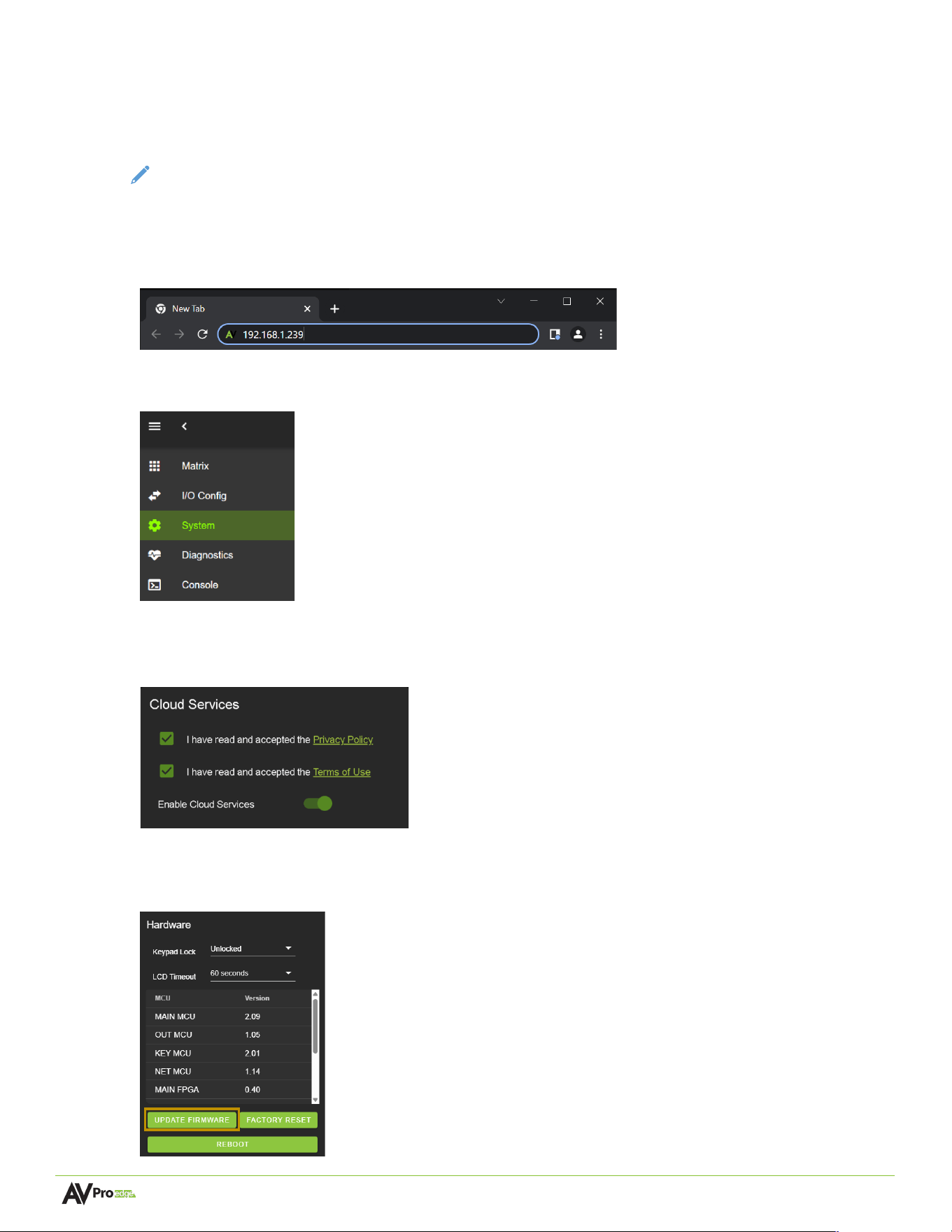
Cloud Services and Firmware Updates
Cloud Services allows OTA (Over-the-Air) firmware updates to be performed onto the unit. This allows the
unit to search the Cloud for the latest versions of firmware If the Cloud Services setting is disabled, the unit
will not be able to access OTA firmware updates.
NOTE:
When updating firmware, some settings and configurations may revert to their original factory
default settings and may need to be re-applied after the firmware updates are complete. It is always
recommended to backup and save your settings and configurations before updating firmware.
1 Enter the unit’s IP address into a Chrome or Edge web browser to access the unit’s Web UI.
2 Navigate to the System tab page.
3 In the Cloud Services section, review the Privacy Policy and Terms of Use, then check both boxes and select
the Enable Cloud Services toggle setting.
IMPORTANT:
This is a required step in order for the unit to
perform OTA firmware updates.
4 In the Hardware section, select the Update Firmware button. A new dialog box will open.
Page 27 of 37
AC-MV-41 user manual
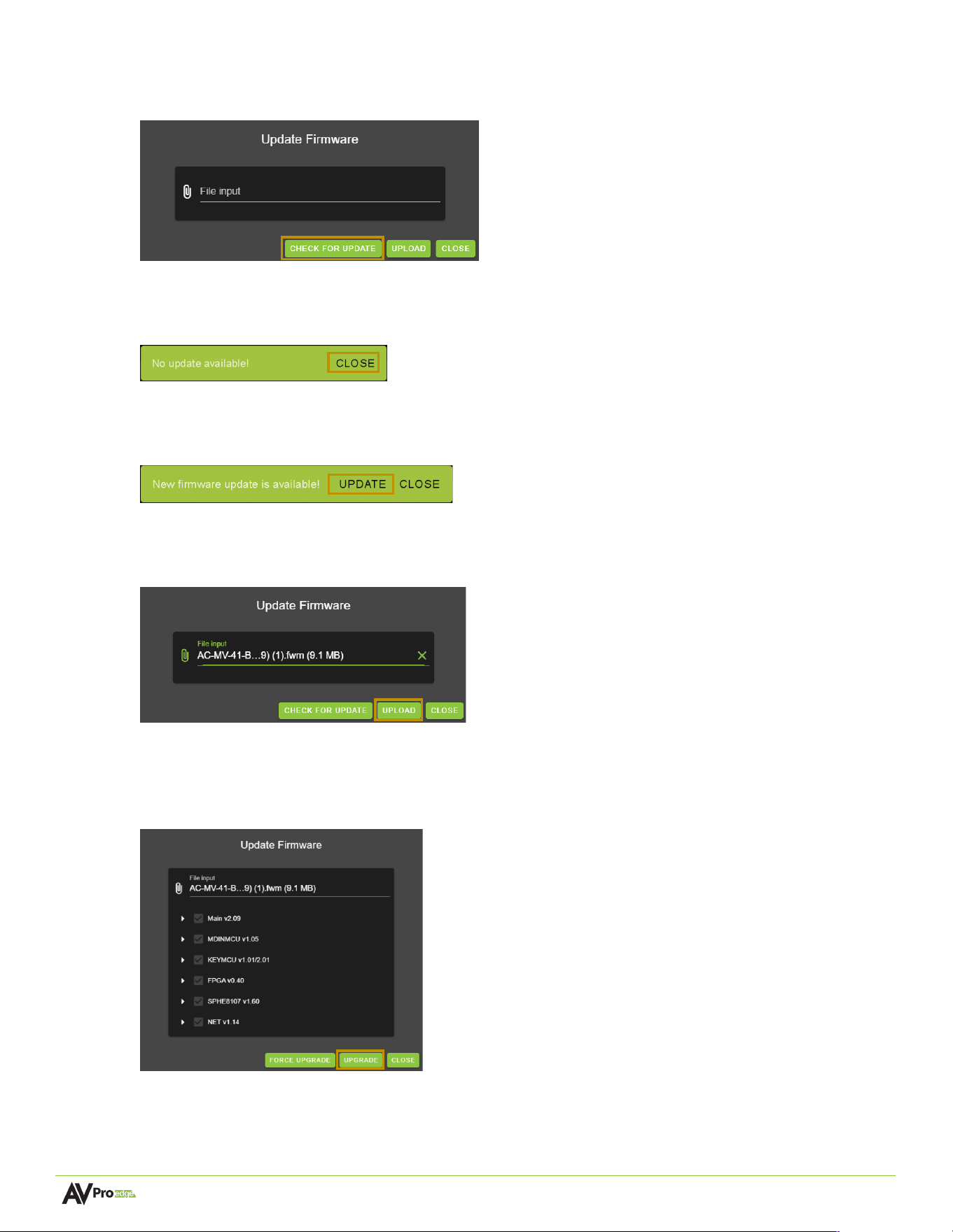
5 In the Update Firmware dialog box, select Check for Update. The unit will now check the Cloud for
available firmware updates.
6 If the unit is already installed with the latest version of firmware, a notification window will prompt the
message “No update available!” at the top of the page. Select the Close button.
7 If a newer version of firmware is detected from the Cloud, a notification window will prompt the
message “New firmware update is available!”. Select the Update button.
8 The unit’s new firmware file will automatically populate into the File input field from the Cloud. Select the
Upload button.
9 From this screen, newer versions of firmware can be viewed before they are installed. Select the
Upgrade button. The unit will now begin installing the latest versions of firmware. DO NOT refresh the
webpage or power off the unit during the update.
10 Once the progress bar reaches 100%, select the Close button. The unit will automatically reboot once the
firmware updates are complete. After the unit reboots, refresh the webpage.
Page 28 of 37
AC-MV-41 user manual
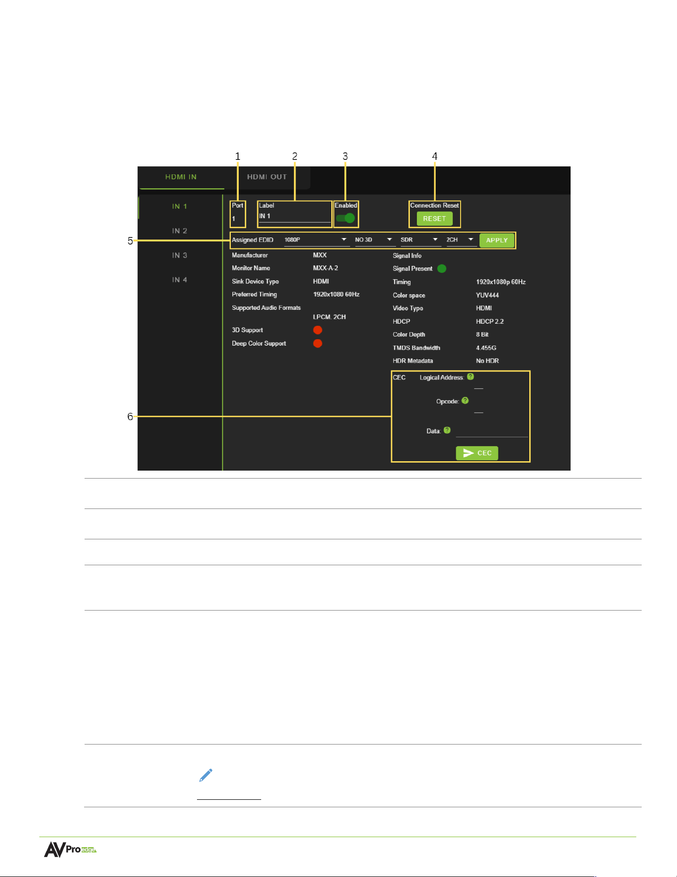
Diagnostics
The Diagnostics menu is designed to troubleshoot issues with EDID, HDMI sources, and HDMI displays. HDMI
connections can be reset, and valuable information about the source and sink devices can be obtained from
the status menus.
HDMI Inputs
1
Port
Indicates the HDMI input port number.
2
Label
Select the text field to enter a custom name for the input. (
Limited to 15 characters
)
3
Enabled
Select the
Enabled
toggle switch to enable (green) or turn off (red) the HDMI input.
4
Connection
Reset
Select the RESET button to reset the HDMI input.
5
EDID
Select the EDID from the drop-down menu. The first drop-down group configures
resolution and refresh rate. The second drop-down group configures dynamic range, with
options for HDR or SDR. The third drop-down group configures the audio channels with
2CH, 6CH, and 8CH options.
NOTE:
When selecting USER1, USER2, or USER3 EDID, the drop-down menus will update,
allowing the user to choose an HDMI Out to copy EDID values. Select one of the four
HDMI Outs and click the COPY button to apply (this replaces the APPLY button).
6
CEC
Select the text fields to input CEC command data to send from the HDMI Input.
NOTE:
Due to the hardware changes, these settings are only available on the
AC-MV-41-B
Page 29 of 37
AC-MV-41 user manual
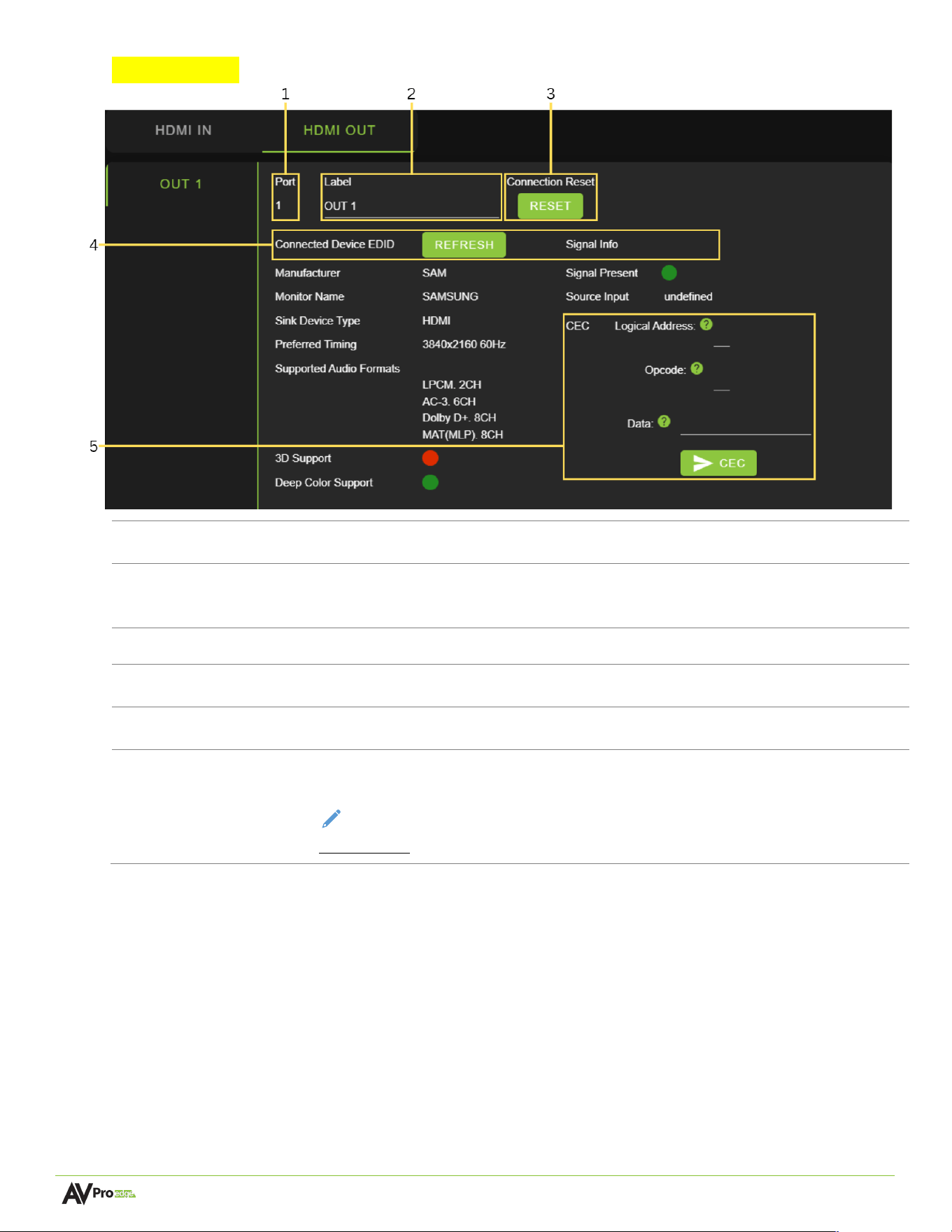
HDMI Outputs
1
Port
Indicates the HDMI output port number.
2
Label
Select the text field to enter a custom name for the output. (
Limited to 15
characters
)
3
Connection Reset
Select the RESET button to reset the HDMI output HPD.
4
5V Reset
Select the RESET button to reset the HDMI output 5V.
5
Refresh
Click the REFRESH button to poll the sink device (display) for EDID information.
6
CEC
Select the text fields to input CEC command data to send from the HDMI output.
NOTE:
Due to the hardware changes, these settings are only available on the
AC-MV-41-B
Page 30 of 37
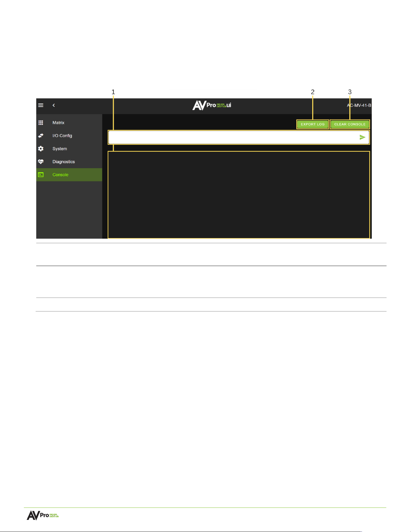
AC-MV-41 user manual
Console
The Web UI features a built-in command console that allows API commands to be sent directly to the unit.
1
Text Field
Enter the unit’s API commands into this field. System events generated by the unit will be
recorded in a continuous stream while the
Console
tab page is open within the Web UI.
2
Export Log
Select to download a .txt file of the information recorded by the console log. The console
log only records information while the unit’s Web UI is opened to the
Console
tab page
and does not record or store information internally.
3
Clear Console
Select to clear the information recorded in the console log.
Page 31 of 37
AC-MV-41 user manual
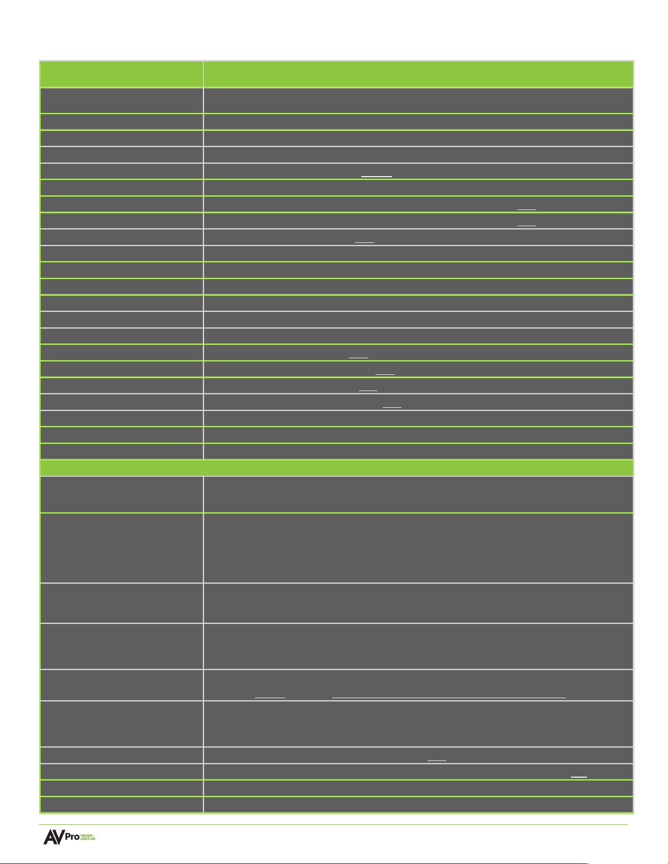
Command List
Command
Action
H
Help
STA
Show Global System Status
SET RST
Reset to Factory Defaults
SET RBT
System Reset to Reboot
SET ADDR xx
Set System Address to xx {xx=00~99}
SET INx HPD RST
Reset Input X hot plug detect to re-establish HDMI handshake {x=[0-4](0=ALL]}
SET OUTx HDMI 5V RST
Reset Output x HDMI 5V to re-establish HDMI handshake {x=0~1}
SET OUTx HPD RST
Reset Output x HDMI 5V to re-establish HDMI handshake {x=0~1}
SET BAUDR x
Set System BaudRate to x{x=0~5}
SET LCD ON Tx
Set LCD Remain On Time{x=[0~3](0=Always ON,1=15,2=30,3=60Sec)}
SET KEY LOCK ON/OFF
Set Key Lock On/Off
SET FAN SPEED x
Set Fan Speed x{x=[0~3]}
GET ADDR
Get System Address
GET STA
Get System System Status
GET BAUDR
Get System BaudRate
GET INx SIG STA
Get Input x Signal Status{x=0~4}
GET INx VID FMT INF
Get Input x Video Format Info{x=0~4}
GET OUTx SIG STA
Get Output x Signal Status{x=0~1}
GET OUTx HPD
Get HDMI Output x HPD Status{x=0~1}
GET LCD ON T
Get LCD Remain On Time
GET KEY LOCK
Get Key Lock Status
GET FAN SPEED
Get Fan Speed Value
Audio/Video Settings Commands: (Note:output number(x)=HDMI,x=[1])
SET OUTx MV LAYOUTy
Set Output x to Multiview Layout y {x=[0~1](0=ALL), y=[0-4](0=PIP OFF,1=2x2
PIP,2=1/3(bottom),3=3+1(left),4=cascade)}
SET MV LAYOUTx INy VC zz
Set Multiview Layout x Input y View Coordinate Value zz
{zz=w1.h1.x1.y1.w2.h2.x2.y2,w1.h1.x1.y1 = Input Captor Cut Param,
w2.h2.x2.y2=Output Captor Display Param x=[1~4],y=[1-4],w1/w2=[0-
3840],h1/h2=[0-2160],x1/x2=[0-3840],y1/y2=[0-2160]}
SET MV PRIORITY x1.x2.x3.x4
Set Multiview Priority Path x1.x2.x3.x4{x1.x2.x3.x4=[1-
4]
Note:NUM 1 indicates the highest priority}
SET MV LAYOUTx NAME LENy
:zz
Set Multiview Layout x Name Length y :zz
{x=[1~20],y=[0-15](Custom Name Length),zz=Custom Name(Space Characters Are
Not Supported)}
SET OUTx ASPRy
Set Output x
VIDEO Aspect Ratio Mode y(Does Not Apply to Video PIP Mode)
{x=[0~1](0=ALL), y=[0-5](0=OFF,1=4/3,2=16/9,3=21/9,4=1.85/1,5=2.35/1)}
SET ASPRMx VCDVy
Set Video Aspect Ratio Mode x Vertical Captor Deletes The Black Edge Value y
{x=[4-5](4=1.85/1,5=2.35/1), y=[0-800]Video Vertical value of the black edge to be
deleted}
GET OUTx MV LAYOUT
Get Output x to Multiview Layout Status{x=0~1}
GET MV LAYOUTx INy VC
Get Multiview Layout x Input y View Coordinate Value Status{x=[1~4],y=0-4}
GET MV LAYOUTx NAME
Get Multiview Layout x Name{x=[0~20](0=All)}
GET MV PRIORITY
Get Multiview Priority Path Status

Page 32 of 37
AC-MV-41 user manual
GET OUTx ASPR
Get Output x VIDEO Aspect Ratio Mode Status{x=0~1}
GET ASPRMx VCDV
Get Video Aspect Ratio Mode x Vertical Captor Deletes The Black Edge Value{x=[4-
5]}
Multiview Audio Settings Commands:
SET AUD MODEx
: Set Multiview Audio Mode x{x=[0-1](0-Follow HDMI Out,1-Follow MVAUD IN)}
Note:If Use VIDEO PIP Mode,MVAUD MODE Automatically Follow MVAUD IN
SET MVAUD INx
: Set Multiview Audio Select Input x {x=[1-8](1-4=HDMI1-4 AUDIO IN,5-8=L & R
AUDIOIN)} NOTE:PIP MODE ON or AUD MODE 1 Takes Effect Automatically
GET AUD MODE
Get Multiview Audio Mode Status
GET MVAUD IN
Get Multiview Audio Select Input Status
Input/Output CEC Settings Commands:
SET INx CEC x1x2.yy.mm.pp
Send CEC Command x1x2.yy.mm.pp for Input x {x=[0-4](0=ALL),x1x2=logical
address: Initiator x1[0~F], Destination x2[0~F];yy=opcode [00~FF],mm=payload
length [0~14], pp=payload [mm bytes]}: Example: [SET IN1 CEC 04.44.01.02]
SET OUTx CEC
x1x2.yy.mm.pp
Send CEC Command x1x2.yy.mm.pp for Output x {x=[0~1](0=ALL),x1x2=logical
address: Initiator x1[0~F], Destination x2[0~F];yy=opcode [00~FF],mm=payload
length [0~14], pp=payload [mm bytes]}: Example: [SET OUT1 CEC
40.84.3.10.00.05]
SET CECRX INx ON/OFF
Set CEC Received Hex Byte From Input x Source On/OFF{x=[0~4](0=ALL)}
SET CECRX OUTx ON/OFF
Set CEC Received Hex Byte From Outputx Sink On/OFF{x=[0~1](0=ALL)}
GET CECRX INx
Get CEC Received Hex Byte From Input x Source On/OFF Status{x=[0~4](0=ALL)}
GET CECRX OUTx
Get CEC Received Hex Byte From Outputx Sink On/OFF Status{x=[0-1](0=ALL)}
Output Setup Commands: (Note:output number(x)=HDMI,x=[1])
SET OUTx VS INy
Set Output x To Input y{x=0~1, y=[1~4]}
SET OUTx VFMTy
: Set Output x Video Timing Format{x=[0-1](0=ALL), y=[0-5]}
{(0=1080P60Hz,1=4K30Hz,2=4K60Hz,3=1080p59.94Hz,4=4k29.97Hz,5=4k59.94Hz}
SET OUTx FORCE SDR EN/DIS
: Set Output x Force Video SDR EN/DIS{x=[0-1](0=ALL)}
SET OUTx EXA EN/DIS
Set Ex-Audio Output Enable/Disable{x=[0~5](0=ALL,5=MULTIVIEW Audio Out)}
SET OUTx EXADL PHy
: Set Ex-Audio Delay{x=[0~5](0=ALL,5=MULTIVIEW Audio Out),
y=[0~7](0=Bypass,1~7=90,180,270,360,450,540,630MS)}
SET OUTx EXA VOLy
Set Output x EQ-Audio Volume Levely{x=[0-5](0=all,5=MULTIVIEW Audio
Out),y=[0~100]}
SET OUTx EXA VOL+y
: Set Output x EQ-Audio Volume Level Increase + y {x=[0-5](0=all,5=MULTIVIEW
Audio Out),y=[1~100,optional default=1]}
SET OUTx EXA VOL-y
: Set Output x EQ-Audio Volume Level Decrease-y {x=[0-5](0=all,5=MULTIVIEW
Audio Out),y=[1~100,optional default=1]}
SET OUTx EXA BALy
: Set Output x Balance y{x=[0-5](0=all,5=MULTIVIEW Audio Out), y=[0~20, Left = 0,
Right = 20, Balanced = 10]}
SET OUTx EXA BAL+y
: Increase Output x Balance by y {x=[0-5](0=all,5=MULTIVIEW Audio Out),y=[1~20,
optional default=1]}
SET OUTx EXA BAL-y
: Decrease Output x Balance by y {x=[0-5](0=all,5=MULTIVIEW Audio Out),y=[1~20,
optional default=1]}
SET OUTx EXEQ MODEy
: Set Output x EX-Audio Volume EQ Modey{x=[0-5](0=all,5=MULTIVIEW Audio
Out),y=[0~7] y=[0-OFF],[1-Classical],[2-Headphone],[3-Hall],[4-Live],[5-Pop],[6-
Rock],[7-Vocal]}
SET OUTx SPDIF VOLy
Set Output x SPDIF Volume Levely{x=[0-1](0=All),y=[0(OFF),1~100(Audio
Level),101(Bypass)]}
Page 33 of 37
AC-MV-41 user manual
SET OUTx STREAM ON/OFF
SET OUTx STREAM ON/OFF{x=0~1}
GET OUTx VS
Get Output x Video Route{x=0~1}
GET OUTx VFMT
Get Output x Video Timing Format{x=0~1}
GET OUTx FORCE SDR
Get Output x Force Video SDR Status{x=0-1}
GET OUTx EXA
Get Ex-Audio Output Enable/Disable Status{x=[0~5](0=all,5=MULTIVIEW Audio
Out)}
GET OUTx EXADL PH
Get Ex-Audio Output Delay Status{x=[0~5](0=all,5=MULTIVIEW Audio Out)}
GET OUTx EXA VOL
Get Output x extracted audio Volume Level{x=[0-5](0=all,5=MULTIVIEW Audio
Out)}
GET OUTx EXA BAL
Get Output x Balance Value{x=[0-5](0=all,5=MULTIVIEW Audio Out)}
GET OUTx EXEQ MODE
Get Output x EX-Audio Volume EQ Mode Status{x=[0-5](0=all,5=MULTIVIEW
Audio Out)}
GET OUTx SPDIF VOL
Get Output x SPDIF Volume Level{x=[0-1](0=all)}
GET OUTx STREAM
Get Output x Stream ON/OFF Status{x=0~1}
GET OUTx EDID DATA
Get Output x EDID DATA{x=[1]}
Input Setup Commands:
(
Note:input number
(
x
)
=HDMI
(
x
)
,x=[1-4]
)
SET INx EDID y
Set Input x EDID{x=0~4, y=[0~32]}
0:1080P_2CH
1:1080P_6CH
2:1080P_8CH
3:1080P_3D_2CH
4:1080P_3D_6CH
5:1080P_3D_8CH
6:4K30HZ_3D_2CH
7:4K30HZ_3D_6CH
8:4K30HZ_3D_8CH
9:4K60HzY420_3D_2CH
10:4K60HzY420_3D_6CH
11:4K60HzY420_3D_8CH
12:4K60HZ_3D_2CH
13:4K60HZ_3D_6CH
14:4K60HZ_3D_8CH
15:1080P_2CH_HDR
16:1080P_6CH_HDR
17:1080P_8CH_HDR
18:1080P_3D_2CH_HDR
19:1080P_3D_6CH_HDR
20:1080P_3D_8CH_HDR
21:4K30HZ_3D_2CH_HDR
22:4K30HZ_3D_6CH_HDR
23:4K30HZ_3D_8CH_HDR
24:4K60HzY420_3D_2CH_HDR
25:4K60HzY420_3D_6CH_HDR
26:4K60HzY420_3D_8CH_HDR
27:4K60HZ_3D_2CH_HDR
28:4K60HZ_3D_6CH_HDR
29:4K60HZ_3D_8CH_HDR
30:USER1_EDID
31:USER2_EDID
32:USER3_EDID
SET INx EDID CY OUTy
Copy Output y EDID To Input x(USER1 BUF){x=0~4, y=[1]}
SET INx Uy EDID CY OUTz
Copy Output z EDID To User y Buff Input x{x=0~4, y=[1~3],z=[1]}
SET INx EDID Uy DATAz
Write EDID To User y Buffer of Input x{x=0~4, y=[1-3],z=[EDID Data]}
SET INx TMDS ON/OFF
Set Inputx Port Power Status ON/OFF{x=0~4}
SET INx PW ON/OFF
Set Input x Port Power Status ON/OFF{x=0~4}
GET INx EDID
Get Input x EDID Index{x=0~4}
GET INx EDID y DATA
Get Input x EDID y Data{x=[1~4], y=[032]}
GET INx TMDS
Get Input x Port Power Status{x=0~4}
GET INx PW
Get Input x Port Power Status{x=0~4}
GET INx HDMI 5V
Get Input x HDMI 5V power status {x=0~4}
Network Setup Command:
(
xxx=[000-255], zzzz=[0001~9999]
SET RIP xxx.xxx.xxx.xxx
Set Route IP Address to xxx.xxx.xxx.xxx
SET HIP xxx.xxx.xxx.xxx
Set Host IP Address to xxx.xxx.xxx.xxx
SET NMK xxx.xxx.xxx.xxx
Set Net Mask to xxx.xxx.xxx.xxx
SET TIP zzzz
Set TCP/IP Port to zzzz
SET DHCP y
Set DHCP {y=0~1}
GET RIP
Get Route IP Address

Page 34 of 37
AC-MV-41 user manual
GET HIP
Get Host IP Address
GET NMK
Get Net Mask
GET TIP
Get TCP/IP Port
GET DHCP
Get DHCP Status
GET MAC
Get MAC Address

Page 35 of 37
AC-MV-41 user manual
Troubleshooting
• Verify Power -Check that the power supply is properly connected and on an active circuit.
• Verify Connections - Check that all cables are securely connected and properly terminated.
• Verify Current Versions - Check if there are any firmware/software/driver updates available for the devices.
• No Sound - Verify the signal being sent is compatible with the connected devices in the signal chain. Ensure
the device’s volume level is properly adjusted and not set to mute.
Maintenance
To ensure reliable operation of this product as well as protecting the safety of any person using or handling this
device while powered, please observe the following instructions.
• Use the power supplies provided. If an alternate supply is required, check voltage, polarity and that it has
sufficient power to supply the device it is connected to.
• Do not operate these products outside the specified temperature and humidity range given in the above
specifications.
• Ensure there is adequate ventilation to allow this product to operate efficiently.
• Repair of the equipment should only be carried out by qualified professionals as these products contain
sensitive components that may be damaged by any mistreatment.
• Only use this product in a dry environment. Do not allow any liquids or harmful chemicals to come into
contact with these products.
• Clean this unit with a soft, dry cloth. Never use alcohol, paint thinner or benzene to clean this unit.
Damage Requiring Service
The unit should be serviced by qualified service personnel if:
• The DC power supply cord or AC adapter has been damaged
• Objects or liquids have gotten into the unit
• The unit has been exposed to rain
• The unit does not operate normally or exhibits a marked change in performance
• The unit has been dropped or the housing damaged
Support
Should you experience any problems while using this product, first, refer to the Troubleshooting section of this
manual before contacting Technical Support. When calling, the following information should be provided:
• Product name and model number
• Product serial number
• Details of the issue and any conditions under which the issue is occurring
• Clean this unit with a soft, dry cloth. Never use alcohol, paint thinner or benzene to clean this unit.

Page 36 of 37
AC-MV-41 user manual
Warranty
The Basics
AVPro Edge warranties its products that are purchased from all Authorized AVPro Edge Resellers or direct
purchases. Products are guaranteed to be free from manufacturing defects and of sound physical and
electronic condition.
AVPro Edge has developed a warranty that anyone can get behind. We really wanted to take all the “red tape”
out of a warranty and just make is simple. Our 10 YEAR NO BS warranty hinges on 3 elements.
• If you are having trouble, call us. We will attempt to troubleshoot your issue over the phone.
• If it’s broken, we will replace it in advance on our dime and we’ll also cover the return shipping. Repair is
an option too, but it’s YOUR call.
• We know you know what you are doing. We will not make you go through unnecessary steps to
troubleshoot an extender…
Coverage Details
AVPro Edge will replace or repair (at customer choice) the defective product. If the product is out of stock or on
backorder it can either be replaced with a comparable product of equal value/feature set (if available) or
repaired.
Your warranty begins at receipt of product (as confirmed by shipping firm tracking). If tracking information is
unavailable for any reason, the warranty will commence 30 ARO (After Receipt of Order). The coverage
continues for 10 years.
Red Tape
AVPro Edge is not responsible for untraceable purchases or those that were made outside of an authorized
channel.
If we conclude that a product or serial number has been tampered with as identified by warranty seal or
physical examination the warranty will be void. Additionally, excessive physical damage (beyond normal wear &
tear) the warranty may be voided or prorated based on the extent of the damage as examined by an AVPro
Edge representative.
Damage caused by “acts of God” are not covered. They can include natural disasters, power surges, storms,
earthquakes, tornadoes, sink holes, typhoons, tidal waves, hurricanes, or any other uncontrollable event related
to nature.
Damage caused by incorrect installation will not be covered. Incorrect power supply, inadequate cooling,
improper cabling, inadequate protection, static discharge are examples of this.
Products installed or sold by a third party to AVPro Edge will be serviced by the Authorized AVPro Edge Reseller.
Accessories (IR Cables, RS-232, Power Supplies, etc.) are not included in the warranty. We will make acceptable
efforts to source and supply replacements for defective accessories at a discounted rate as needed.
Obtaining an RMA
Dealers, Re-sellers, and Installers can request an RMA from AVPro Edge Tech Support Rep or their Sales
Engineer.

Page 37 of 37
AC-MV-41 user manual
You may also email [email protected] or fill out the general contact form at avproedge.com/contact
End users may not request an RMA directly from AVPro Edge and will be referred back to the Dealer, Re-seller,
or Installer.
Shipping
For USA (not including Alaska and Hawaii). Shipping is covered on advanced replacements for FedEx Ground
(some expressed exceptions may apply). Defective product return shipping is covered by AVPro Edge using an
emailed return label. Items must be returned within 30 days of receipt of the replacement product, after 30
days, the customer will be billed. Other return shipping methods will not be covered.
For International (and Alaska and Hawaii) return shipping costs will be the responsibility of the returnee. Once
the unit is scanned for return shipping AVPro Edge will ship the new unit for replacement.
Limitation on Liability
The maximum liability of AVPro Global Holdings LLC under this limited warranty shall not exceed the actual
purchase price paid for the product. AVPro Global Holdings LLC is not responsible for direct, special, incidental,
or consequential damages resulting from any breach of warranty or condition, or under any other legal theory
to the maximum extent permitted by law. Taxes, Duties, VAT, and freight forwarding service charges are not
covered or paid for by this warranty.
Obsolescence or incompatibility with newly invented technologies (after manufacture of product) is not covered
by this warranty.
Obsolescence is defined as:
“Peripherals are rendered obsolete when current technology does not support product repair or re-
manufacture. Obsolete products cannot be re-manufactured because advanced technologies supersede original
product manufacturer capabilities. Because of performance, price and functionality issues, product
redevelopment is not an option.”
Discontinued or out of production items will be credited at fair market value towards a current product of equal
or comparable capabilities and cost. Fair market value is determined by AVPro Edge.
Exclusive Remedy
To the maximum extent permitted by law, this limited warranty and the remedies set forth above are exclusive
and in lieu of all other warranties, remedies, and conditions, whether oral or written, express or implied. To the
maximum extent permitted by law, AVPro Global Holdings LLC specifically disclaims any and all implied
warranties, including, without limitation, warranties of merchantability and fitness for a particular purpose. If
AVPro Global Holdings LLC cannot lawfully disclaim or exclude implied warranties under applicable law, then all
implied warranties covering this product, including warranties of merchantability and fitness for a particular
purpose, shall apply to this product as provided under applicable law.
This warranty supersedes all other warranties, remedies, and conditions, whether oral or written, express or
implied.