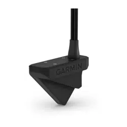
PANOPTIX
™
LIVESCOPE
™
LVS32-TH
INSTALLATION INSTRUCTIONS
Important Safety Information
WARNING
See the Important Safety and Product Information guide in the product box for product warnings and other
important information.
The device must be installed with at least one of the included anti-rotation bolts. Failure to do so could result in
the device rotating while the boat is moving and could cause damage to your vessel.
You are responsible for the safe and prudent operation of your vessel. Sonar is a tool that enhances your
awareness of the water beneath your boat. It does not relieve you of the responsibility of observing the water
around your boat as you navigate.
CAUTION
Failure to install and maintain this equipment in accordance with these instructions could result in damage or
injury.
To avoid possible personal injury, always wear safety goggles, ear protection, and a dust mask when drilling,
cutting, or sanding.
NOTICE
When drilling or cutting, always check what is on the opposite side of the surface to avoid damaging the vessel.
To obtain the best performance and to avoid damage to your boat, you must install the Garmin
®
transducer
according to these instructions.
Read all installation instructions before proceeding with the installation. If you experience difficulty during the
installation, contact Garmin Product Support.
Software Update
You must update the Garmin chartplotter software when you install this device. For instructions on updating the
software, see your chartplotter owner's manual at support.garmin.com.
Tools Needed
• Drill
• 3mm bit (
1
/
8
in.)
• 9mm bit (
3
/
8
in.)
• 12mm bit (
1
/
2
in.) (metal hull)
• 13mm bit (
1
/
2
in.) (fiberglass hull)
• 32mm spade bit (1
1
/
4
in.) (fiberglass hull)
• 38mm hole saw (1
1
/
2
in.) (metal hull)
• Bandsaw or table saw
• Slip-joint pliers or crescent wrench
• Masking tape
• Marine sealant
• Solvent wash
• Marine-grade epoxy or exposed core sealant that can be used on plastic (cored fiberglass hull)
GUID-5E426607-6188-4AA3-9748-2D0AB5008783 v3June 2022
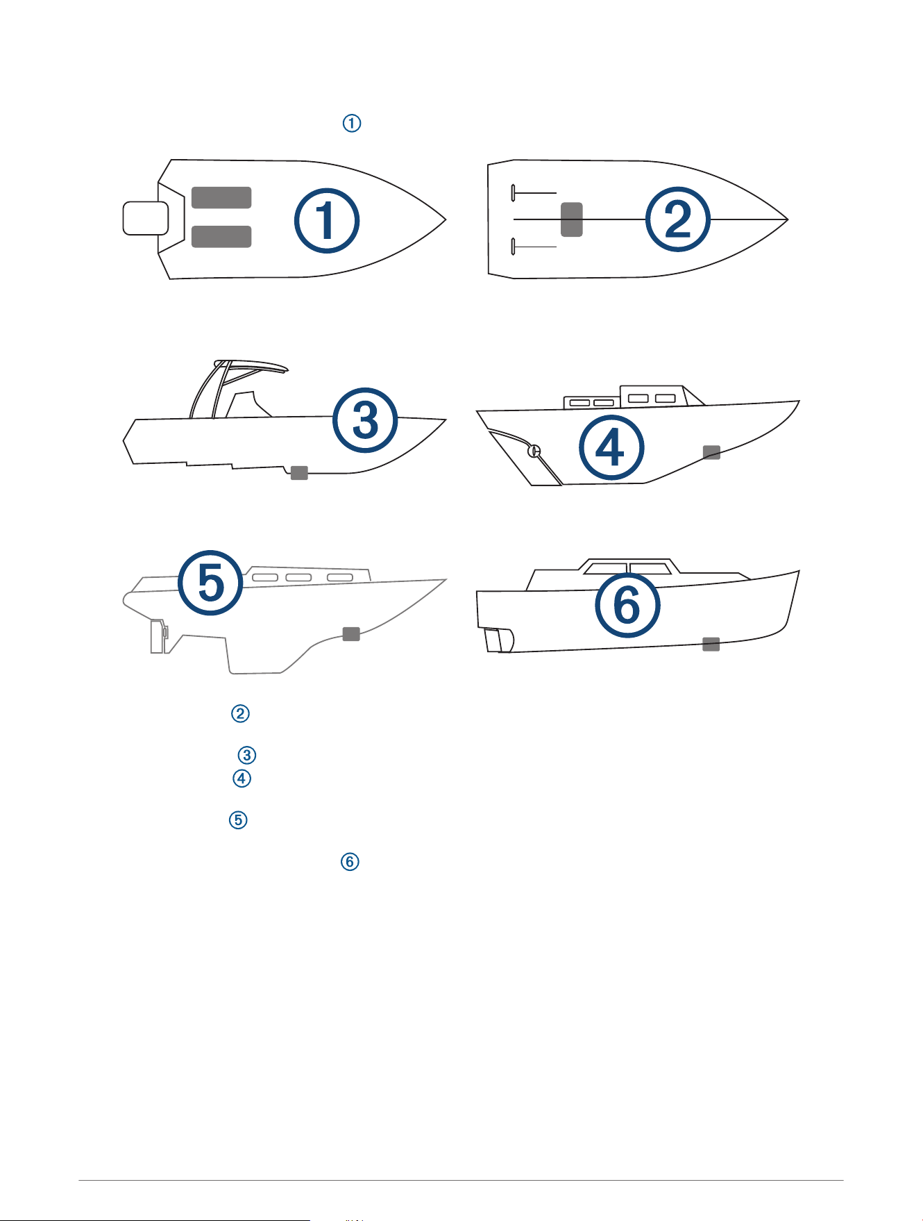
Mounting Considerations
•
On outboard and sterndrive vessels , you should mount in front of and close to the engine or engines.
• On inboard vessels , you should mount the transducer in front of and far away from the engine propeller
and shaft.
• On step-hull vessels , you should mount the transducer in front of the first step.
• On full-keel vessels , you should mount the transducer at a slight angle that aims at the bow, not parallel to
the centerline.
• On fin-keel vessels , you should mount the transducer from 25cm to 75cm (from 10to 30in.) in front of
the keel and a maximum of 10cm (4in.) to the side of the centerline.
• On vessels with displacement hulls , you should mount the transducer approximately
1
/
3
aft of the
waterline length of the vessel from the bow, and from 150 to 300mm (from 6 to 12in.) to the side of the
centerline.
• You should mount the transducer in a location where it will not be jarred when launching, hauling, or storing.
• You should mount the transducer in a location where it is not behind strakes, struts, fittings, water intake or
discharge ports, thru-hull transducers, or anything that creates air bubbles or causes the water to become
turbulent. Turbulent water may interfere with the sonar beam.
• You should mount the transducer in a location where there are no bulkheads or stringers on the interior of the
boat that impede a clear surface for the fairing block.
• You should mount the transducer as close to the center line of the boat as possible.
2
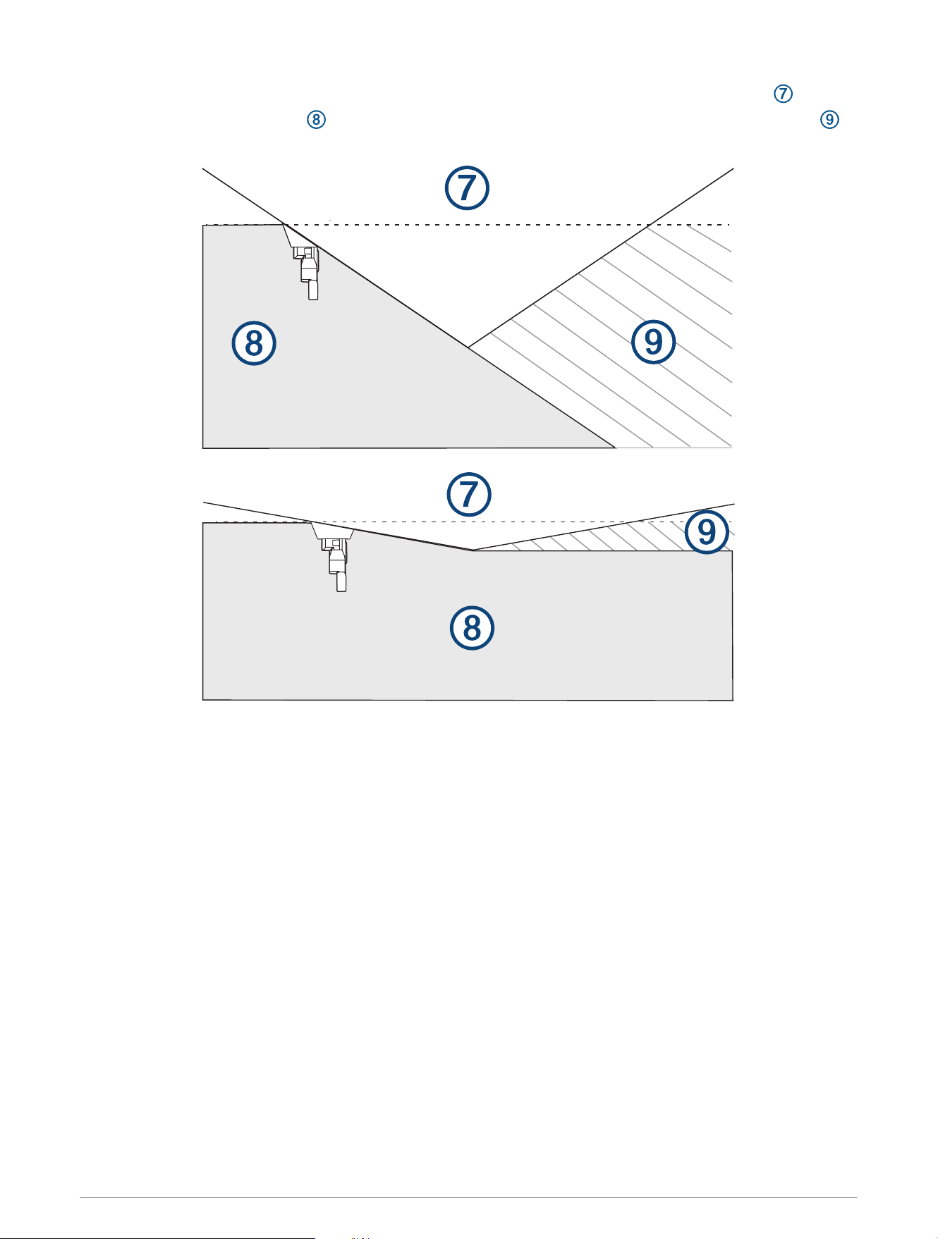
•
When mounted farther from the center of the transom, a greater deadrise can cause the boat hull to
interfere with the sonar beam , and can cause inconsistent detection on the opposite side of the boat .
These illustrations show the transducer from behind.
• On single-drive vessels, you must not mount the transducer in the path of the propeller.
• On twin-drive vessels, you should mount the transducer between the drives, if possible.
• You must install the sonar module in a location with adequate ventilation, where it will not be exposed to
extreme temperatures.
• You should mount the sonar module in a location where the LEDs are visible.
• You should mount the sonar module in a location where the cables can be easily connected.
Fairing Block Angle Cut
A fairing block positions your transducer parallel to the water line for increased sonar accuracy. You must
measure the deadrise angle of your boat hull to determine if a fairing block is necessary to mount the
transducer. If the deadrise angle of your mounting location exceeds 5°, you should use a fairing block to mount
the transducer.
Deadrise Angle
Deadrise is the angle formed between a horizontal line and a boat hull at a single point. You can measure the
deadrise angle with a smartphone application, an angle finder, a protractor, or a digital level. You can also ask
your boat manufacturer for the deadrise angle of the specific point on your boat hull.
NOTE: A boat may have several deadrise angles depending on the shape of the hull. Measure the deadrise angle
only at the location where you plan to install the transducer.
3
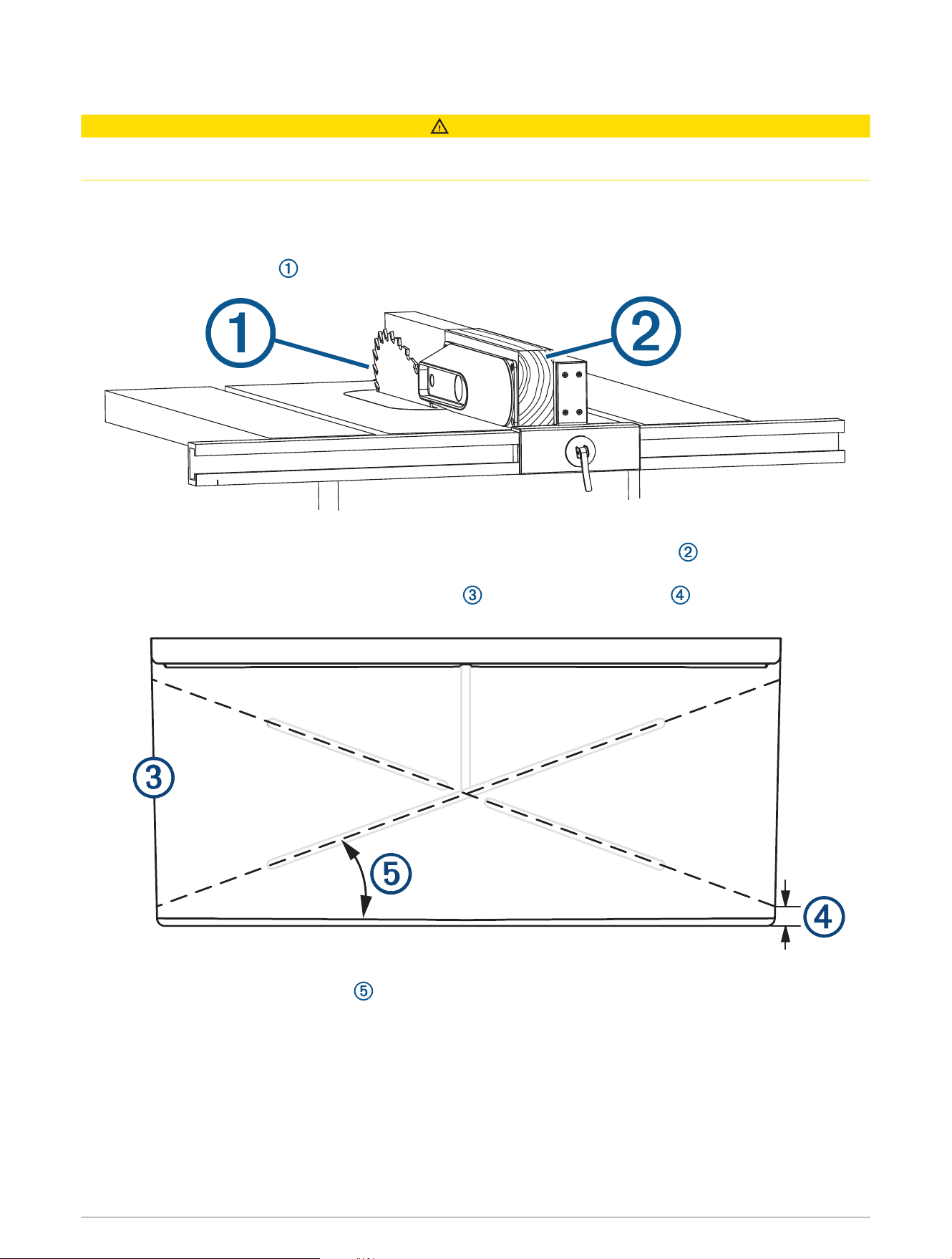
Cutting the Fairing Block
CAUTION
To avoid possible personal injury, always wear safety goggles, ear protection, and a dust mask when drilling,
cutting, or sanding.
1 Using wood screws, attach the fairing block to a piece of wood.
The wood becomes a cutting guide for the fairing block.
2 Measure the deadrise angle of the hull at the mounting location.
3 Tilt your table saw blade to match the deadrise angle and secure the cutting fence.
4 Position the fairing block on the table so the cutting guide rests against the fence and the angle matches
the angle of the mounting location.
5 Adjust the cutting fence to ensure the fairing block has a minimum thickness of 2mm (
1
/
16
in.).
NOTE: The maximum cutting angle of the fairing block is 25°.
6 Cut the fairing block.
7 Using a rasp or power tool, shape the fairing block to the hull as precisely as possible.
8 Use the remaining section of the fairing block as the backing block inside the hull.
4

Mounting the GLS
™
10 Black Box Device
NOTICE
If you are mounting the device in fiberglass, when drilling the pilot holes, use a countersink bit to drill a
clearance counterbore through only the top gel-coat layer. This will help to avoid cracking in the gel-coat layer
when the screws are tightened.
NOTE: Screws are included with the device, but they may not be suitable for the mounting surface.
Before you mount the device, you must select a mounting location, and determine what screws and other
mounting hardware are needed for the surface.
1 Place the black box device in the mounting location, and mark the location of the pilot holes.
2 Drill a pilot hole for one corner of the device.
3 Loosely fasten the device to the mounting surface with one corner, and examine the other three pilot-hole
marks.
4 Mark new pilot-hole locations if necessary, and remove the device from the mounting surface.
5 Drill the remaining pilot holes.
6 Secure the device to the mounting location.
Blink Codes
After the sonar module is installed, it turns on when the chartplotter is turned on. The color status LED on the
sonar module indicates its operational status.
LED Color State Status
Green Blinking
The sonar module is connected to a chartplotter and is operating
properly. You should see sonar data on the chartplotter.
Red Blinking
The sonar module is turned on, but is not connected to a chartplotter,
or is waiting to connect to a chartplotter. If the sonar module is
connected to the chartplotter and this code persists, check the wiring
connections.
Orange Blinking A software update is in progress.
Red/Green Blinking Reserved
Red
Two blinks followed by a
3-second pause
Other sonar failure.
Red
Three blinks followed by a
3-second pause
The transducer is not detected by the sonar module. If this code
persists, check the wiring connections.
Red
Five blinks followed by a
3-second pause
The sonar module input voltage exceeds the maximum input voltage.
5
Cored Fiberglass Boat Hull Installation Instructions
6
Installing a Thru-Hull Transducer with a Fairing Block
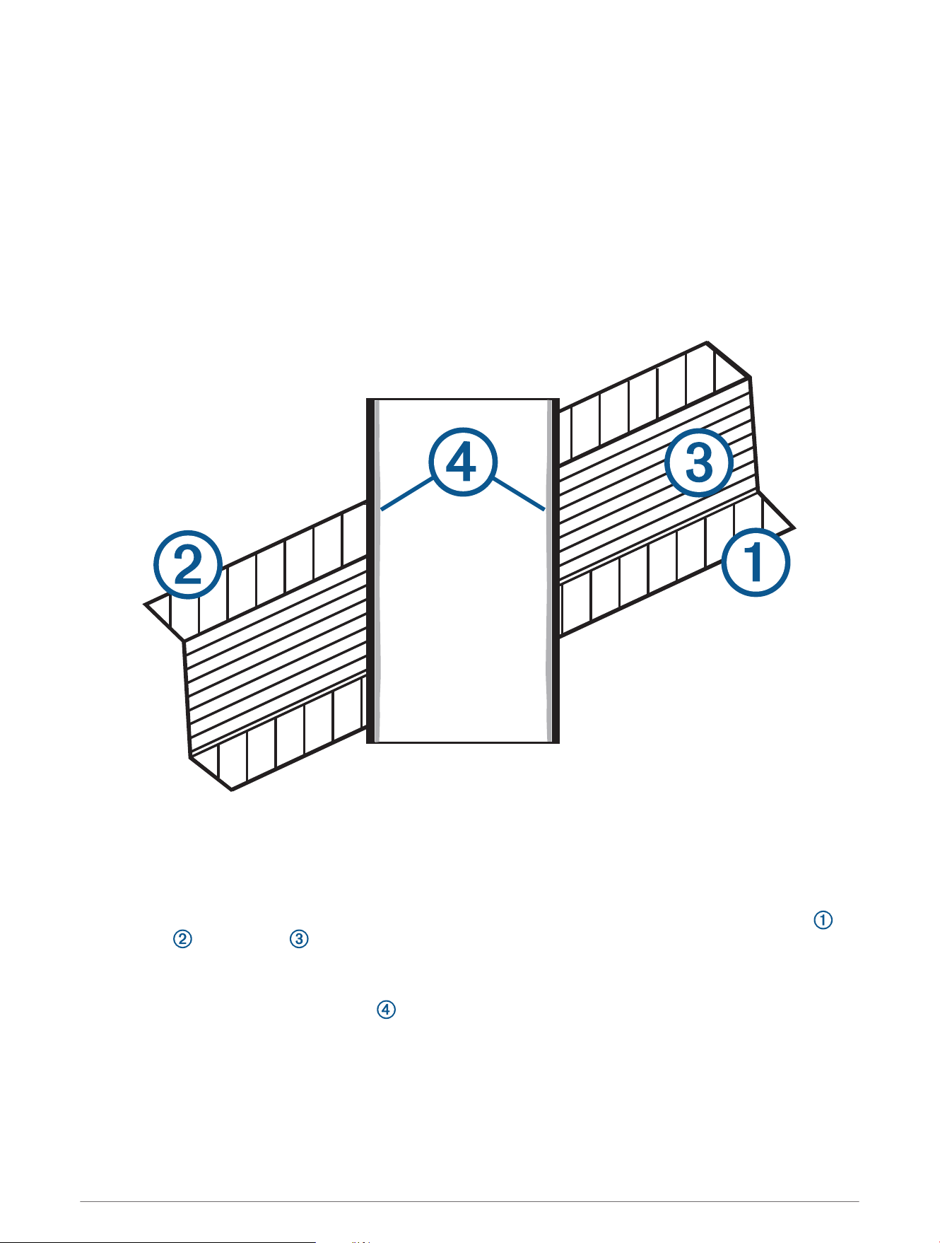
Drilling the Transducer Stem Hole and the Anti-Rotation Bolt Hole in a Cored Fiberglass Hull
Before you can drill the hole for the anti-rotation bolt, you must drill the hole for the transducer stem (Drilling the
Transducer Stem Hole and the Anti-Rotation Bolt Hole in a Cored Fiberglass Hull, page7) and you must cut the
fairing block (Cutting the Fairing Block, page4).
The core must be cut and sealed carefully to protect against water seepage.
1 Select a mounting location without surface irregularities or obstructions.
2 Using the template, mark the location of the stem hole and anti-rotation bolt.
3 Drill a 3mm (
1
/
8
in.) pilot hole through the template and hull at the stem hole location.
The hole must be perpendicular to the water surface.
4 Place masking tape over the pilot hole and surrounding area outside the hull to prevent damage to the
fiberglass.
5 Using a 32mm (1
1
/
4
in.) bit at the stem hole location, drill from outside the hull through the outer skin ,
inner skin , and the core .
The hole must be perpendicular to the water surface.
6 Sand and clean the inner skin, core, and outer skin around the hole.
7 Seal the exposed inner core with epoxy , and allow the epoxy to set thoroughly.
8 While holding a drill with a 9mm (
3
/
8
in.) bit plumb, drill the anti-rotation bolt hole through the hull from
outside the hull.
The hole must be perpendicular to the water surface.
9 Sand and clean the area around the hole with a solvent wash to remove dust particles.
7

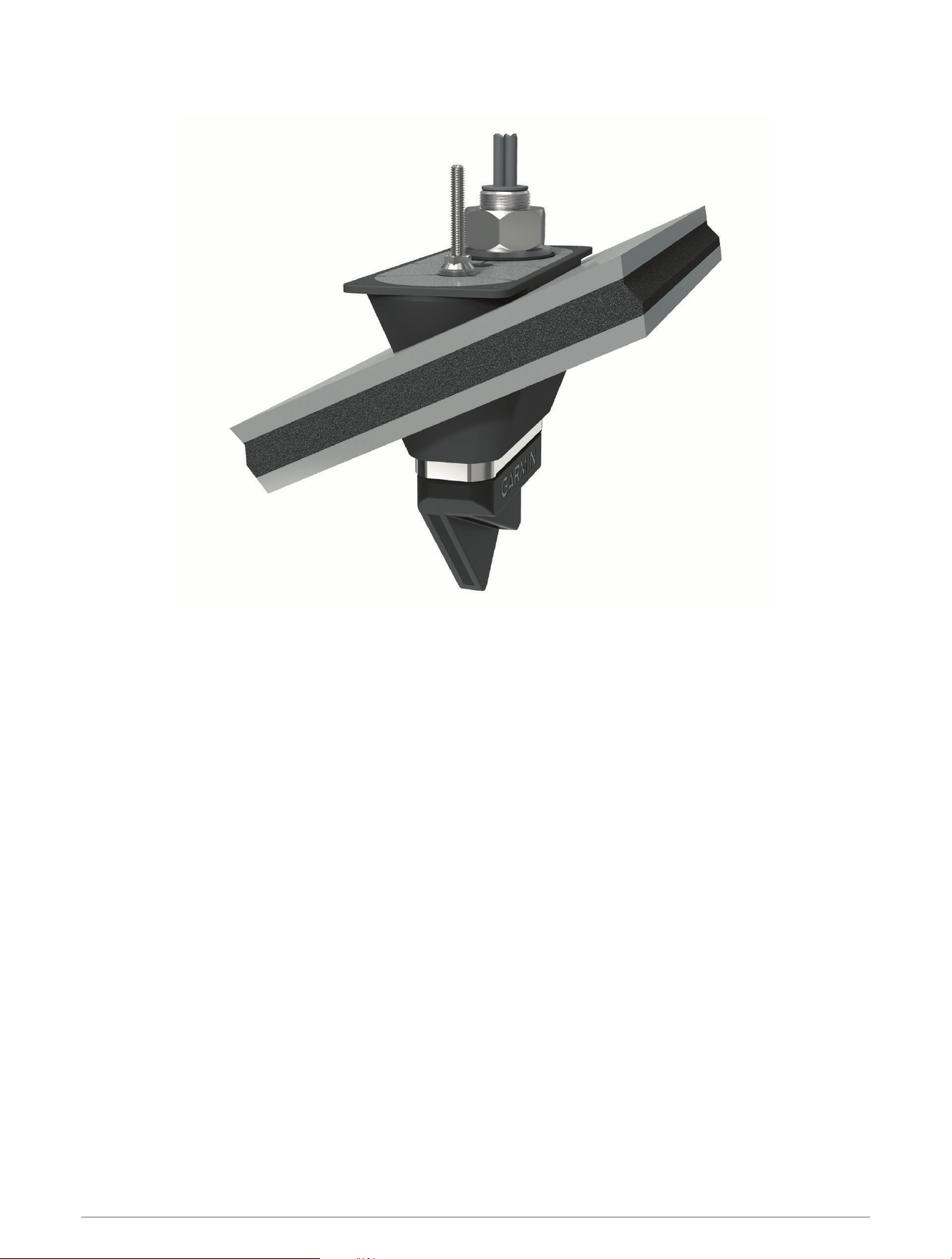
Applying Marine Sealant to a Thru-Hull Transducer
You must apply marine sealant to the transducer to ensure a tight, waterproof seal between the fairing block
and the hull. Do not apply sealant directly to the stem or anti-rotation bolt.
Apply marine sealant around the base of the stem and anti-rotation bolt on the transducer.
8

Installing the Transducer with a Fairing Block
It is recommended that two installers complete these instructions, with one positioned outside the boat and one
inside the boat.
NOTE: When installing the transducer in a cored fiberglass hull, avoid over-tightening the nuts to prevent
damaging the hull.
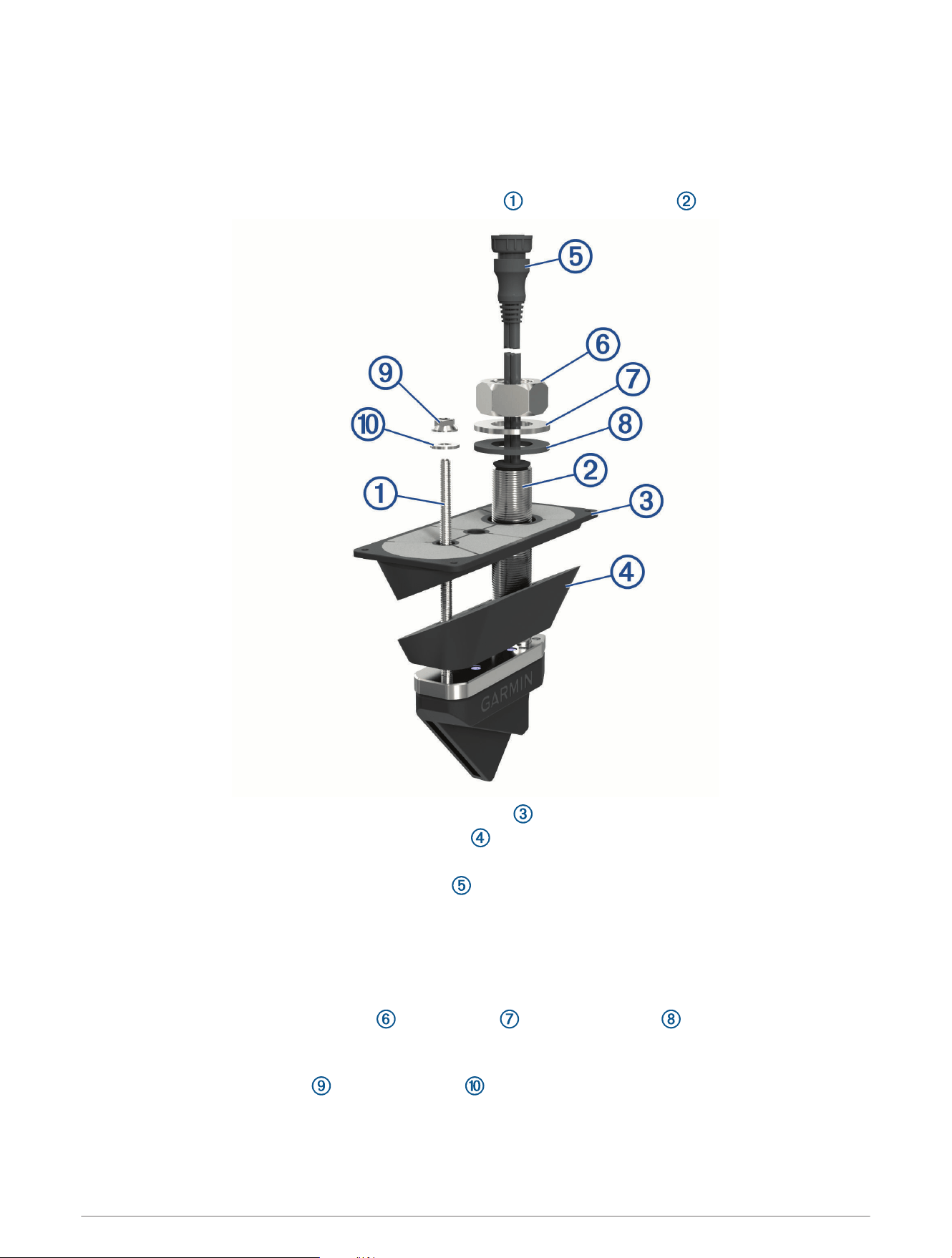
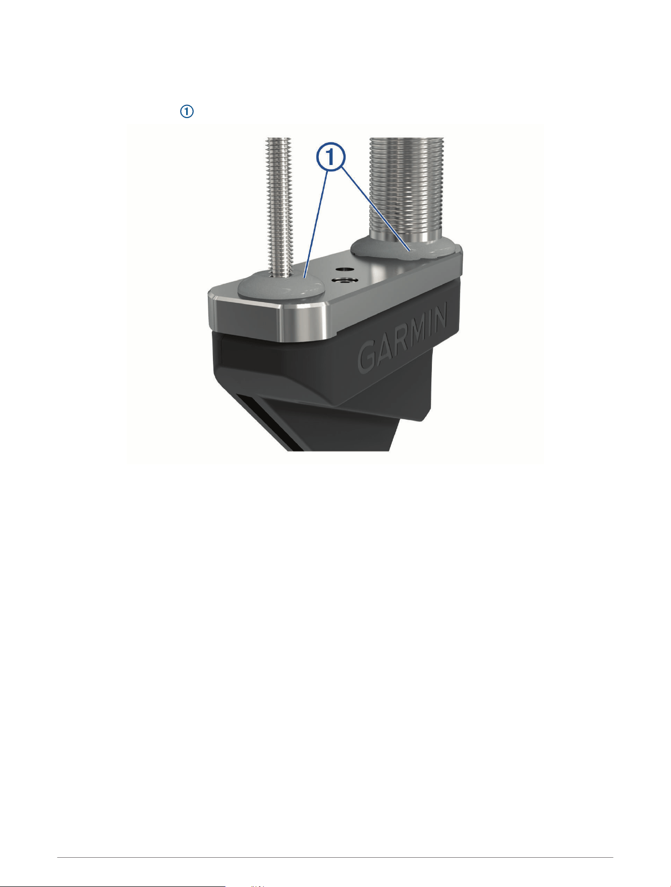
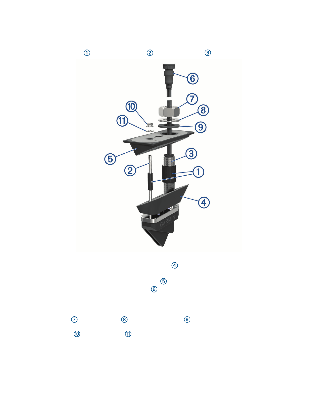
1 Apply marine sealant at the base of the anti-rotation bolt and transducer stem .
2 Seat the transducer housing firmly within the fairing block recess.
3 Apply marine sealant to the face of the fairing block that must contact the hull.
4 Apply marine sealant to the face of the backing block that must contact the inner hull.
5 From outside the hull, insert the transducer cable and transducer stem through the mounting hole.
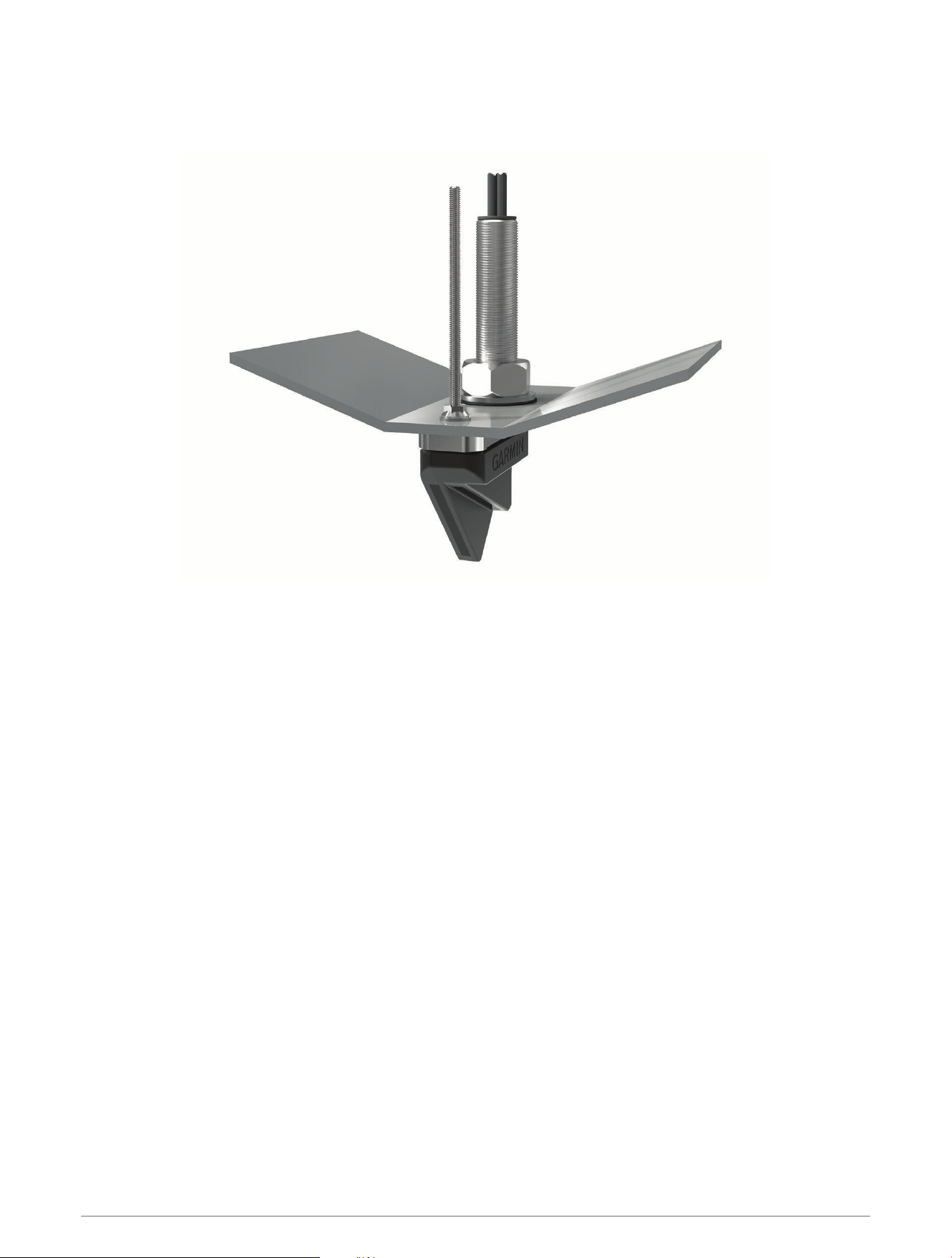
6 From inside the hull, slide the backing block onto the transducer stem and seat it firmly against the inner hull.
The fairing and transducer must be parallel to the keel.
7 From inside the hull, apply the included anti-seize compound to the exposed transducer stem and anti-
rotation bolt.
8 From inside the hull, use slip-joint pliers or a crescent wrench to secure the backing block to the transducer
stem with the included 46mm hull nut , nylon washer , and rubber washer .
Do not over-tighten the hull nut.
9 From inside the hull, use slip-joint pliers or a crescent wrench to secure the backing block to the anti-rotation
bolt with the included M8 nut and 8mm washer .
Do not over-tighten the M8 nut.
10 Before the sealant hardens, remove all excess sealant on the outside of the fairing block and exterior hull to
ensure smooth water flow over the transducer.
9
Non-cored/Fiberglass/Wooden Boat Hull Installation Instructions
Thru-Hull Transducer in a Non-cored/Fiberglass Hull with a Fairing Block
If the deadrise angle of your mounting location exceeds 5°, you should use a fairing block to mount the device.
Drilling the Transducer Stem Hole and the Anti-Rotation Bolt Hole in a Non-Cored or Fiberglass Hull
Before you can drill holes for the anti-rotation bolts, you must drill the hole for the transducer stem, and you
must cut the fairing block (Cutting the Fairing Block, page4).
You should follow these instructions when you are using a fairing block to mount the transducer on a boat that
does not have a cored fiberglass hull.
1 Select a mounting location without surface irregularities or obstructions.
2 Using the template, mark the location of the stem hole and anti-rotation bolt.
3 Drill a 3mm (
1
/
8
in.) pilot hole through the hull at the stem hole location, from outside the hull.
The hole must be perpendicular to the water surface.
4 If the vessel has a fiberglass hull, place masking tape over the pilot hole and surrounding area outside the
hull to prevent damage to the fiberglass.
5 If you taped over the pilot hole, use a utility knife to cut out the hole in the tape.
6 While holding a 32mm (1
1
/
4
in.) spade bit plumb, cut a hole from outside the hull at the stem hole location.
The hole must be perpendicular to the water surface.
7 Sand and clean the area around the hole.
8 While holding a drill with a 9mm (
3
/
8
in.) bit plumb, drill the anti-rotation bolt hole through the hull.
The holes must be perpendicular to the water surface.
9 Sand and clean the area around the holes with a solvent wash to remove dust particles.
10

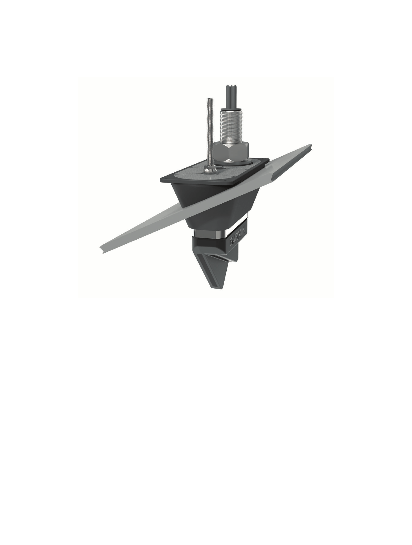
Applying Marine Sealant to a Thru-Hull Transducer
You must apply marine sealant to the transducer to ensure a tight, waterproof seal between the fairing block
and the hull. Do not apply sealant directly to the stem or anti-rotation bolt.
Apply marine sealant around the base of the stem and anti-rotation bolt on the transducer.
11
Installing the Transducer with a Fairing Block
It is recommended that two installers complete these instructions, with one positioned outside the boat and one
inside the boat.
NOTE: When installing the transducer in a cored fiberglass hull, avoid over-tightening the nuts to prevent
damaging the hull.
1 Apply marine sealant at the base of the anti-rotation bolt and transducer stem .
2 Seat the transducer housing firmly within the fairing block recess.
3 Apply marine sealant to the face of the fairing block that must contact the hull.
4 Apply marine sealant to the face of the backing block that must contact the inner hull.
5 From outside the hull, insert the transducer cable and transducer stem through the mounting hole.
6 From inside the hull, slide the backing block onto the transducer stem and seat it firmly against the inner hull.
The fairing and transducer must be parallel to the keel.
7 From inside the hull, apply the included anti-seize compound to the exposed transducer stem and anti-
rotation bolt.
8 From inside the hull, use slip-joint pliers or a crescent wrench to secure the backing block to the transducer
stem with the included 46mm hull nut , nylon washer , and rubber washer .
Do not over-tighten the hull nut.
9 From inside the hull, use slip-joint pliers or a crescent wrench to secure the backing block to the anti-rotation
bolt with the included M8 nut and 8mm washer .
Do not over-tighten the M8 nut.
10 Before the sealant hardens, remove all excess sealant on the outside of the fairing block and exterior hull to
ensure smooth water flow over the transducer.
12
Thru-Hull Transducer in a Non-cored/Fiberglass Hull without a Fairing Block
If the deadrise angle of your mounting location does not exceed 5°, you can mount the device without a fairing
block.
Drilling the Transducer Stem and Anti-Rotation Bolt Holes
You should follow these instructions if you are installing your transducer on a fiberglass boat and you are not
using a fairing block or isolator plate.
1 Trim the included transducer template.
2 Select a mounting location without surface irregularities or obstructions.
3 Using the template, mark the location of the stem hole and anti-rotation bolt.
4 While holding a 32mm (1
1
/
4
in.) spade bit plumb, drill the transducer stem hole from outside the hull.
The hole must be perpendicular to the water surface.
5 While holding a drill with an 9mm (
3
/
8
in.) bit plumb, drill the anti-rotation bolt hole from outside the hull.
The holes must be perpendicular to the water surface.
6 Sand and clean the inner skin, core, and outer skin around the holes.
13
Applying Marine Sealant to a Thru-Hull Transducer
You must apply marine sealant to the transducer to ensure a tight, waterproof seal between the fairing block
and the hull. Do not apply sealant directly to the stem or anti-rotation bolt.
Apply marine sealant around the base of the stem and anti-rotation bolt on the transducer.
14
Installing the Transducer without a Fairing Block
It is recommended that two installers complete these instructions, with one positioned outside the boat and one
inside the boat.
NOTE: When installing a transducer in a non-cored fiberglass hull, avoid over-tightening the nuts to prevent
damaging the hull.
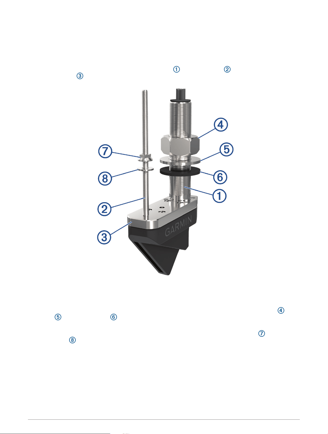
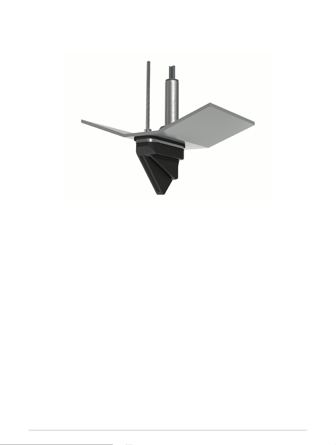
1 Apply marine sealant to the base of the transducer stem , anti-rotation bolt , and the sides of the
transducer plate that must contact the hull.
2 From outside the hull, insert the transducer through the mounting hole and seat it firmly against the hull.
3 From inside the hull, apply the included anti-seize compound to the exposed transducer stem and anti-
rotation bolt.
4 From inside the hull, use slip-joint pliers or a crescent wrench to secure the included 46mm hull nut , nylon
washer , and rubber washer to the transducer stem.
Do not over-tighten the hull nut.
5 From inside the hull, use slip-joint pliers or a crescent wrench to secure the included M8 nut and 8mm
nylon washer to the anti-rotation bolt.
Do not over-tighten the M8 nut.
6 Before the sealant hardens, remove all excess sealant on the outside of the exterior hull to ensure smooth
water flow over the transducer.
15

Metal Boat Hull Installation Instructions
Thru-Hull Transducer in a Metal Hull with a Fairing Block
If the deadrise angle of your mounting location exceeds 5°, you should use a fairing block to mount the device.
Drilling the Transducer Stem Hole and the Anti-Rotation Bolt Hole in a Metal Hull
You should follow these instructions when you are using a fairing block to mount the transducer on a boat that
has a metal hull.
1 Select a mounting location without surface irregularities or obstructions.
2 Using the template, mark the location of the stem hole and anti-rotation bolt.
3 Drill a 3mm (
1
/
8
in.) pilot hole through the hull at the stem hole location, from outside the hole.
The hole must be perpendicular to the water surface.
4 Using a 38mm (1
1
/
2
in.) hole saw, cut the stem hole from outside the hull.
The hole must be perpendicular to the water surface.
5 While holding a drill with a 13mm (1/2in.) bit plumb, drill the anti-rotation bolt hole through the hull from
outside the hull.
6 Sand and clean the area around the holes.
16

Applying Marine Sealant to a Thru-Hull Transducer
You must apply marine sealant to the transducer to ensure a tight, waterproof seal between the fairing block
and the hull. Do not apply sealant directly to the stem or anti-rotation bolt.
Apply marine sealant around the base of the stem and anti-rotation bolt on the transducer.
17
Installing the Transducer with a Fairing Block and Bushings
It is recommended that two installers complete these instructions, with one positioned outside the boat and one
inside the boat.
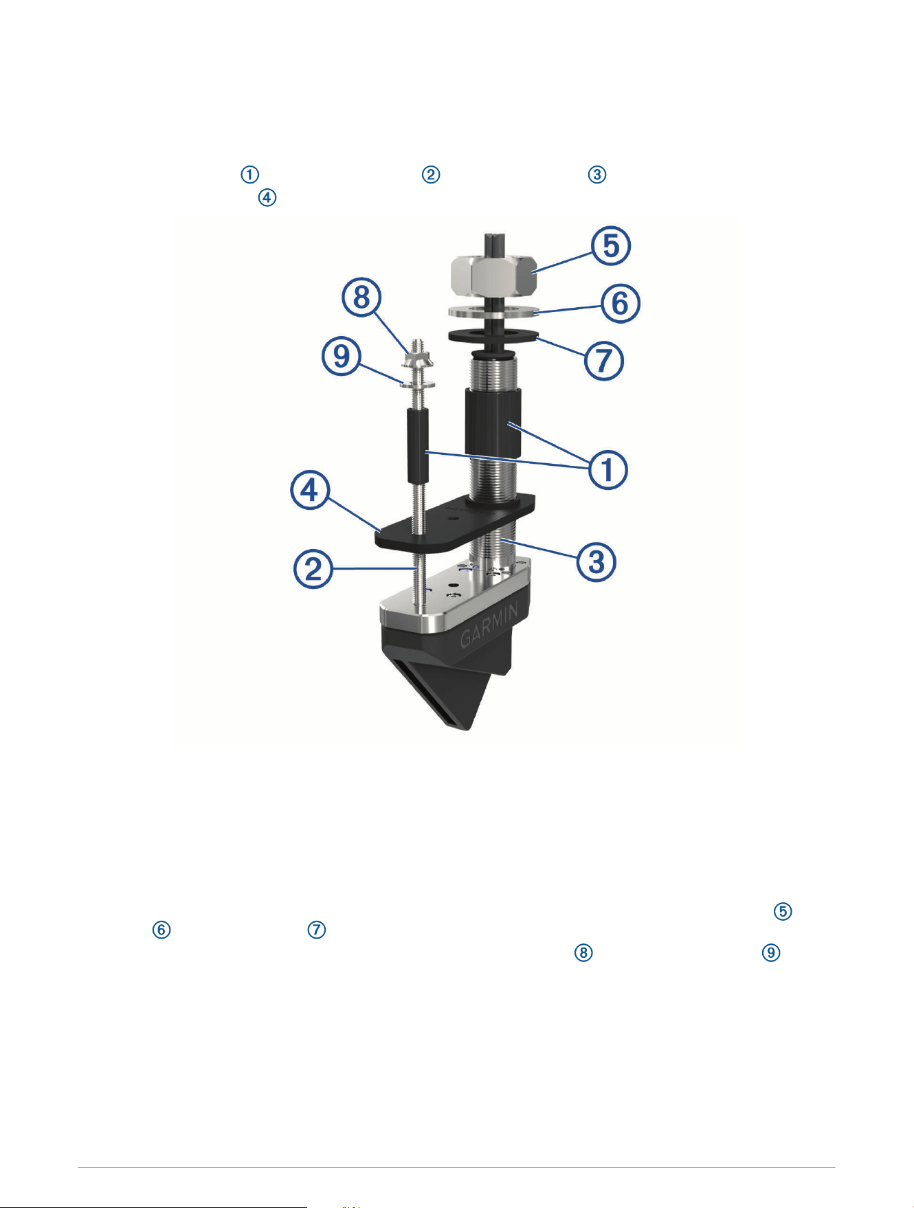
1 Secure the bushings to the anti-rotation bolt and transducer stem .
2 Apply marine sealant to the bushings, and at the base of the anti-rotation bolt and transducer stem.
3 Seat the transducer housing firmly within the fairing block recess.
4 Apply marine sealant to the side of the fairing block that must contact the hull.
5 Apply marine sealant to the side of the backing block that must contact the hull.
6 From outside the hull, insert the transducer cable and transducer housing through the mounting hole.
7 From inside the hull, slide the backing block onto the transducer and seat it firmly against the hull.
8 Apply the included anti-seize compound to the exposed transducer stem and anti-rotation bolt.
9 From inside the hull, use slip-joint pliers to secure the backing block to the transducer stem with the included
46mm hull nut , the nylon washer , and the rubber washer .
10 From inside the hull, use slip-joint pliers to secure the backing block to the anti-rotation bolts with the
included M8 nut and 8mm washer .
11 Before the sealant hardens, remove all excess sealant on the outside of the fairing block and exterior hull to
ensure smooth water flow over the transducer.
18
Thru-Hull Transducer in a Metal Hull without a Fairing Block
If the deadrise angle of your mounting location does not exceed 5 degrees, you can mount the device without a
fairing block.
Drilling the Transducer Stem and Anti-Rotation Bolt Holes
You should follow these instructions if you are mounting your transducer on a metal hull boat and you are not
using a fairing block.
1 Trim the included transducer template.
2 Select a mounting location without surface irregularities or obstructions.
3 Using the template, mark the location of the stem hole and anti-rotation bolt.
4 Drill a 3mm (
1
/
8
in.) pilot hole through the hull at the stem hole location, from outside the hull.
5 Using a 38mm (1
1
/
2
in.) hole saw, cut the stem hole from outside the hull.
The hole must be perpendicular to the water surface.
6 While holding a drill with a 12mm (
1
/
2
in.) bit plumb, drill the anti-rotation bolt hole from outside the hull.
The holes must be perpendicular to the water surface.
7 Remove the template from the mounting location.
8 Sand and clean the area around the holes with a solvent wash to remove dust particles.
19
Installing the Transducer in a Metal Hull without a Fairing Block
It is recommended that two installers complete these instructions, with one positioned outside the boat and one
inside the boat.
NOTE: When installing a transducer in an aluminum or steel hull, you must use the included isolation plate.
1 Secure the bushings to the anti-rotation bolt and transducer stem .
2 Seat the isolation plate firmly against the transducer.
3 Apply marine sealant to the base of the transducer stem and anti-rotation bolt, and the side of the isolation
plate that must contact the hull.
NOTE: Apply enough marine sealant on all surfaces to ensure bonding between the plate and the hull,
including a tight perimeter seal.
4 From outside the hull, insert the transducer through the mounting hole and seat it firmly against the hull.
5 From inside the hull, apply the included anti-seize compound to the exposed transducer stem and anti-
rotation bolts.
6 From inside the hull, use slip-joint pliers or a crescent wrench to secure the included 46mm hull nut , nylon
washer , and rubber washer to the transducer stem.
7 From inside the hull, use slip-joint pliers to secure the included M8 nut and 8mm nylon washer to the
anti-rotation bolt.
8 Before the sealant hardens, remove all excess sealant on the outside of the exterior hull to ensure smooth
water flow over the transducer.
20

Maintenance
Testing the Installation
NOTICE
You should check your boat for leaks before you leave it in the water for an extended period of time.
Because water is necessary to carry the sonar signal, the transducer must be in the water to work properly. You
cannot get a depth or distance reading when out of the water. When you place your boat in the water, check for
leaks around any screw holes that were added below the water line.
Anti-Fouling Paint
To prevent corrosion of metal and to slow the growth of organisms that can affect a vessel's performance, you
should apply a water-based anti-fouling paint to the transducer every six months.
NOTE: Never apply ketone-based anti-fouling paint to your vessel, because ketones attack many types of plastic
and could damage or destroy your transducer.
Cleaning the Transducer
Aquatic fouling accumulates quickly and can reduce your device's performance.
1 Remove the fouling with a soft cloth and mild detergent.
2 If the fouling is severe, use a scouring pad or putty knife to remove growth.
3 Wipe the device dry.
Specifications
LVS32-TH Specifications
Dimensions (L x H x W) 136.4 x 96.5 x 44.5mm (5.37 x 3.8 x 1.75in.)
Weight (transducer only) 850g (1.87lb.)
Frequencies From 530 to 1,100kHz
Operating temperature From 0 to 40°C (from 32 to 104°F)
Storage temperature From -40 to 85°C (from -40 to 185°F)
Maximum depth/distance
1
61m (200ft.)
Field of view
Front to back: 135degrees
Side-to-side: 20degrees
1
Dependent upon water salinity, bottom type, and other water conditions.
21

GLS 10 Sonar Module Specifications
Dimensions (W x H x D) 245 x 149 x 65 mm (9.7 x 5.9 x 2.6 in.)
Weight 1.96 kg (4.33 lbs.)
Operating temperature From -15° to 70°C (from 5° to 158°F)
Storage temperature From -40° to 85°C (from -40° to 185°F)
Power input From 10 to 32 Vdc
Power usage 21 W typical, 24 mW min., 58 W max.
Compass-safe distance 178 mm (7 in.)
Data output Garmin Marine Network
Open-Source Software License
To view the open-source software license(s) used in this product, go to developer.garmin.com/open-source
/linux/.
© 2019 Garmin Ltd. or its subsidiaries
Garmin
®
, ActiveCaptain
®
, and the Garmin logo are trademarks of Garmin Ltd. or its subsidiaries, registered in the USA and other countries. LiveScope
™
and Panoptix
™
are
trademarks of Garmin Ltd. or its subsidiaries. These trademarks may not be used without the express permission of Garmin.
Android
™
is a trademark of Google Inc. Apple
®
and Mac
®
are trademarks of Apple Inc., registered in the U.S. and other countries. Wi‑Fi
®
is a registered trademark of Wi-Fi
Alliance Corporation. Windows
®
is a registered trademark of Microsoft Corporation in the United States and other countries. Other trademarks and trade names are those
of their respective owners.
© 2019 Garmin Ltd. or its subsidiaries
support.garmin.com