Ice-O-Matic
11100 East 45th Ave
Denver, Colorado 80239
Part Number 9081264-01 Rev.
P P
rint Date 11/22/16
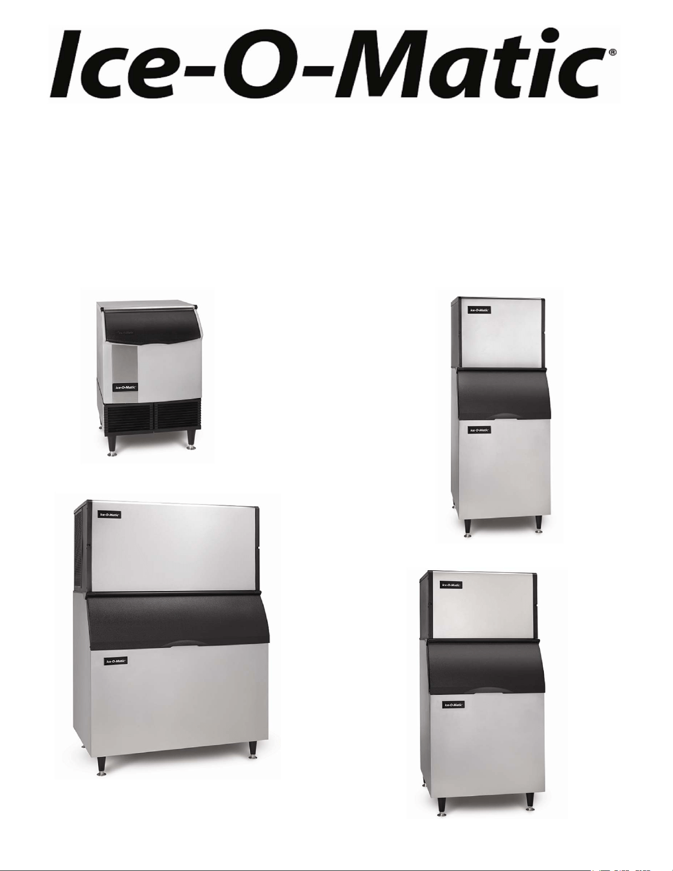
Installation, Start-Up and Maintenance Manual
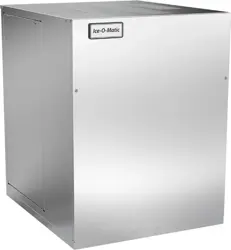
ICE SERIES CUBERS
ICE0250 through ICE2100 Series*
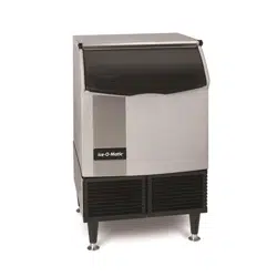
ICEU150, ICEU220 and ICEU300 Undercounter Series*
ICE0320, ICE0520, ICE0726, ICE0926 22 Inch Series*
*INCLUDES 230/50/1 VOLT UNITS

ICE Series Introduction
Page i
How To Use This Manual
Ice-O-Matic provides this manual as an aid to the service technician in installation and maintenance of the
ICE Series (electro-mechanical) cube ice machines. Do not attempt to perform installation, start-up or
maintenance unless you have read and fully understand this manual.
For a Service Provider, please reference our “Find a Service Technician” tab at www.iceomatic.com
Keep this manual for future reference.
The ICE Series Service Parts Manuals are available separately.
Ice-O-Matic icemakers and dispensers are not approved for outdoor installation.
WARNING: Always disconnect electrical power and shut off water supply whenever maintenance or
repairs are performed on the ice machine and related equipment.
CAUTION: Always wear protective eyewear whenever maintenance or repairs are performed on the ice
machine and related equipment.
Ice-O-Matic has partnered with ENERGY STAR since 2004 to ensure our customers receive the
most efficient ice machines for your investment dollar. Ice-O-Matic is committed to the continuous
improvement in both energy efficiency and productivity thereby delivering the best value in energy
efficient ice machines money can buy.
For a detailed list of ENERGY STAR qualified Ice-O-Matic ice machines, go to:
http://www.iceomatic.com/Products/Sales-Literature/#
Plant-a-Tree Program
As part of our commitment to the global environment, Ice-O-Matic is devoted to sustainability in
every aspect of our business. To offset the carbon footprint of our factory in Denver, we not only
recycle materials in our packaging and manufacturing but also recycle our industrial and office
waste products.
More important, we partner with AMERICAN FORESTS and plant a tree for every ice machine
we sell, thereby supporting reforestation of key regions throughout the world. Our goal is to
plant 150,000 trees through our Global Sustainability program. Trees reduce topsoil erosion,
prevent harmful land pollutants from getting into our waterways and replace air pollutants with
fresh, clean oxygen.
Ice-O-Matic Warranty
Every Ice-O-Matic ice maker is backed by a warranty that provides both parts and labor coverage. To view the
warranty details, register products, or check your warranty status visit the “Warranty and Water Filter Registration”
page on www.iceomatic.com

ICE Series Table of Contents
Page ii
Introduction Page i
Warranty Page i
Table of Contents Page ii
Freight Claim Procedure Page iii
Model Number and Serial Number Format Page 1
Installation Guidelines Page 2
Remote Condenser Guidelines Page 4
Electrical and Plumbing Requirements Page 6
How the Machine Works Page 15
Start-Up Procedure Page 16
General Maintenance Page 18
Cleaning Procedure Page 19
Cabinet Care Page 21
Winterizing Procedure Page 22
Maintenance Record Page 23

ICE Series Freight Claim Procedure
Page iii
Freight Claims Important!
Inspect Promptly
This merchandise has been carefully inspected and packed in accordance with the carrier’s packing specifications.
Responsibility for safe delivery has been assumed by the carrier. If loss or damage occurs, you as the consignee must
file a claim with the carrier and hold the container for carrier’s inspection.
Visible Loss or Damage
Any external evidence of loss or damage must be fully described and noted on your freight bill or express receipt and
signed by the carrier’s agent. The claim should be filed on a form available from the carrier.
Concealed Loss or Damage
If loss or damage does not appear until merchandise has been unpacked, make a written request for inspection by the
carrier within 15 days of the delivery date. Then file a claim on a form from the carrier.
File Claim Without Delay
Do Not Return Damaged Merchandise to Ice-O-Matic
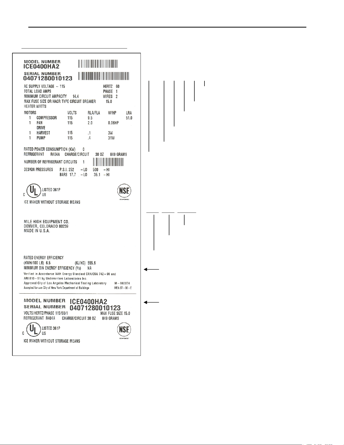
ICE Series Model and Serial Number Format
Page 1
Model and Serial Number Format
The serial number format and machine specifics are detailed on the
data plate.
ICE 040 0 H A 2
Design Level
Condenser Type: A=Air, W=Water, R=Remote
Cube Size: H=Half, F=Full
Voltage: 0=115V, 6=230V/60Hz. 5=240V/50Hz.
(x10) Approximate Production in 24 hours @70FAir/50FWater
Series: Environmental Cuber (Uses HFC Refrigerant)
This format is 14 characters long and begins with a date code
followed by the Ice-O-Matic identifier, and then a sequential
number. This is an entirely numerical serial number.
The serial number will look like the example.
0407 1280 010077
010077 is the serial identifier.
1280 is the identifier. (Ice-O-Matic)
0407 is the date code, in YYMM format. (2004 July)
Large data plate will be placed on the back of the unit.
Small data plate will be placed by the service valves
.
The date code will change monthly and yearly to reflect the date of
manufacture.
Note: Sam
p
le of Serial Number Data Plate

ICE Series Installation Guidelines
Page 2
Installation Guidelines
For proper operation of the Ice-O-Matic ice machine, the following installation guidelines must be followed. Failure to
do so may result in loss of production capacity, premature part failures, and may void all warranties.
Reference the installation parameters prior to installing the machine:
Ambient Operating Temperatures
Minimum Operating Temperature: 50°F (10°C)
Maximum Operating Temperature 100°F (38°C), 110°F (43°C) on 50 Hz. Models.
Note: Ice-O-Matic icemakers and dispensers are not approved for outdoor installation.
Incoming Water Supply (See Electrical and Plumbing Diagrams for line sizing)
Minimum incoming water temperature: 40°F (4.5°C)
Maximum incoming water temperature: 100°F (38°C)
Minimum incoming water pressure: 20 psi (1.4 bar) (0,138MPa)
Maximum incoming water pressure: 60 psi (4.1 bar) (0.414 MPa)
Note: If water pressure exceeds 60 psi (4.1 bar), a water pressure regulator must be installed.
Drains
All drain lines must be installed per local codes. Flexible tubing is not recommended. Route bin drain, purge drain and
water condenser drain individually to a floor drain. The use of condensate pumps for draining water is not
recommended by Ice-O-Matic. Ice-O-Matic assumes no responsibility for improperly installed equipment.
Note: The purge drain fitting is plastic; DO NOT apply heat to the purge drain area; DO NOT overtighten.
Water Filtration
A water filter system should be installed with the ice machine.
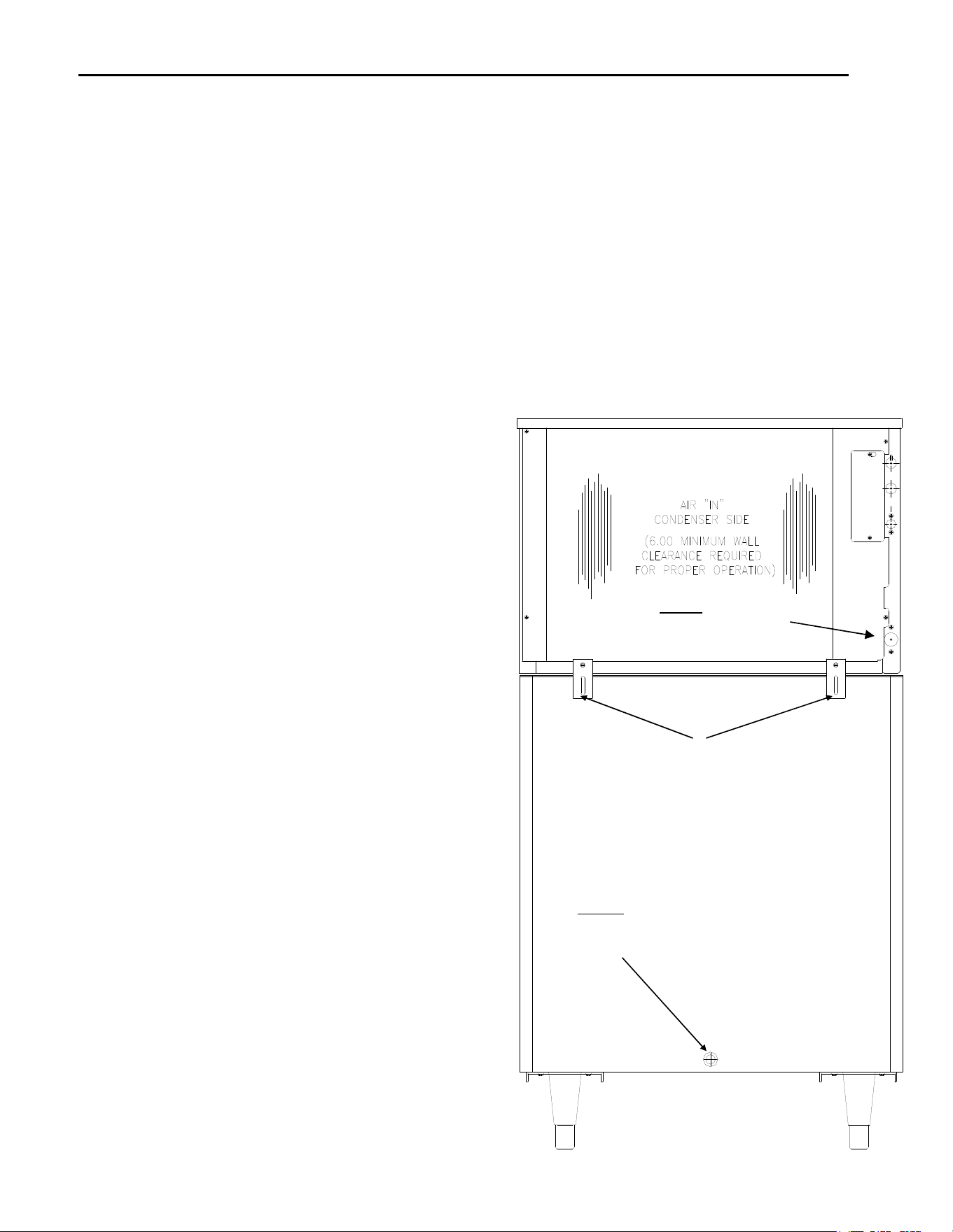
Clearance Requirements
Self-contained air cooled ice machines must have a minimum of 6 inches (15cm) of clearance at the rear, top, and
sides of the ice machine for proper air circulation. Exceptions such as Top Air Discharge machines will be listed in the
machine specification sections.
Stacking
Ice-O-Matic does not endorse stacking ice machines.
Dispenser Application
A thermostatic bin control kit should be installed if the ICE Series ice machine is placed on a dispenser. A bin top may
or may not be required. (Exception is the CD400 Series Dispenser)
Electrical Specifications
Refer to the serial plate at the rear of the ice machine to make sure proper voltage and circuit breaker size have been
supplied. Make sure the machine is on a dedicated circuit. European installations require that the electrical supply
fixed wiring must be provided with a disconnect means having a separation of at least 3mm in all poles. The ice
machines are provided without an electrical cord set and are designed and agency approved to be permanently
connected.
The 115 volt Undercounter series ice makers are supplied with an electrical cord, all other ice makers will
need to be installed and wired per local electrical codes. A GFI outlet is not approved.
Caution: Electrical connection must be made or a cord installed by a qualified electrician or there is danger of an
electrical fire.
Adjustments
Level the machine within 1/8 inch in all directions.
Check the bin control for proper adjustment.
Check the water in the water trough for proper level.
Check the ice bridge for proper thickness.
Check the water regulating valve adjustment if water cooled.
ICE Series Installation Guidelines
Page 3
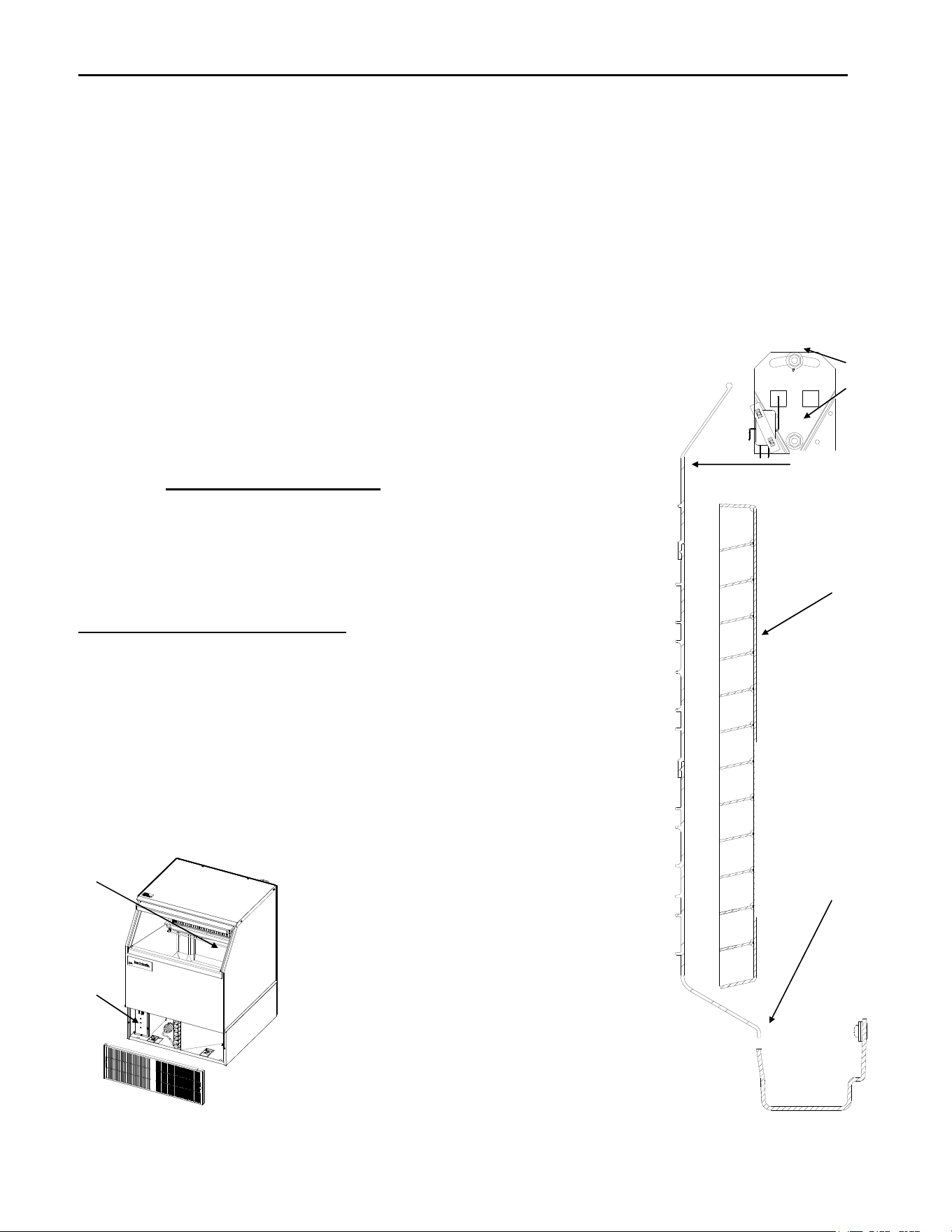
Remove the bin carton and tip the bin on its back to remove the skid and attach the bin legs.
Secure the machine on top of the bin or dispenser.
Attach the ice machine to the bin with the mounting straps provided with the bin or dispenser. Insure that the back of
the ice machine is flush with the back of the bin. Proper functioning of the bin door requires the bin door, when it is
opened, to be in a stable position.
If the ice machine is too far forward on the bin, the opened door may not be stable, resulting in an unexpected closing
of the bin door. If the ice machine is to be mounted on a bin or dispenser other than an Ice-O-Matic, refer to the
manufacturers instructions for machine mounting. Ice-O-Matic will not be responsible for damage or injury that results
from unexpected closing of the bin door as a result of the ice machine being too far forward on the bin.
Important!
A water filtration system should be installed with all ice machines. Check the filter manufacturer's instructions for
proper installation.
All water supply lines must be installed per local codes.
Use 1/4 inch O.D. minimum on air cooled machines. On
water cooled machines 3/8 inch O.D. minimum tubing
must be run to the condenser. The water supply for the
float can “T” off from the condenser line using 1/4 inch
O.D. minimum tubing. Make 2 coils of extra tubing so that
the machine can be pulled away from the wall if service is
needed.
All drain lines must be installed per local codes. The
purge drain should be a minimum of 5/8 inch O.D. tubing.
The condenser drain on water cooled units should be 3/8
inch O.D. minimum. The drain line fittings on Ice-O-Matic
bins are 3/4 FPT. The bin drain should be a minimum of
3/4 inch O.D. Cold water drains should be insulated to
prevent condensation from forming.
Warning!
Do not apply heat directly to the back of bin as
damage may occur to plastic parts.
Do not over tighten the purge drain fitting as damage
may occur to plastic parts.
Connect power supply to the terminal block in the control
box or at the rear junction box if equipped.
Ensure the machine is level within 1/8 inch in all
directions.
Remove any shipping or packaging material.
If the machine has a remote condenser, reference the
Remote Condenser Installation Guidelines.
Once the machine has been installed, follow the
start-up procedures.
IMPORTANT!
Attach the ice machine to the bin or
dispenser with the provided
mounting hardware. Insure the back
of the ice machine is flush with the
back of the bin.
Warning!
Do not apply heat directly to the
back of bin as damage may occur
to plastic parts.
Warning! Do not over tighten as
damage may occur to plastic
parts.

ICE Series Remote Condenser Guidelines
Page 4
Remote Condenser Installation
For proper operation of the Ice-O-Matic ice machine, the following installation guidelines must be followed. Failure to do
so may result in loss of production capacity, premature part failure, and may void all warranties.
Use the following for planning the placement of the remote condenser relative to the ice machine.
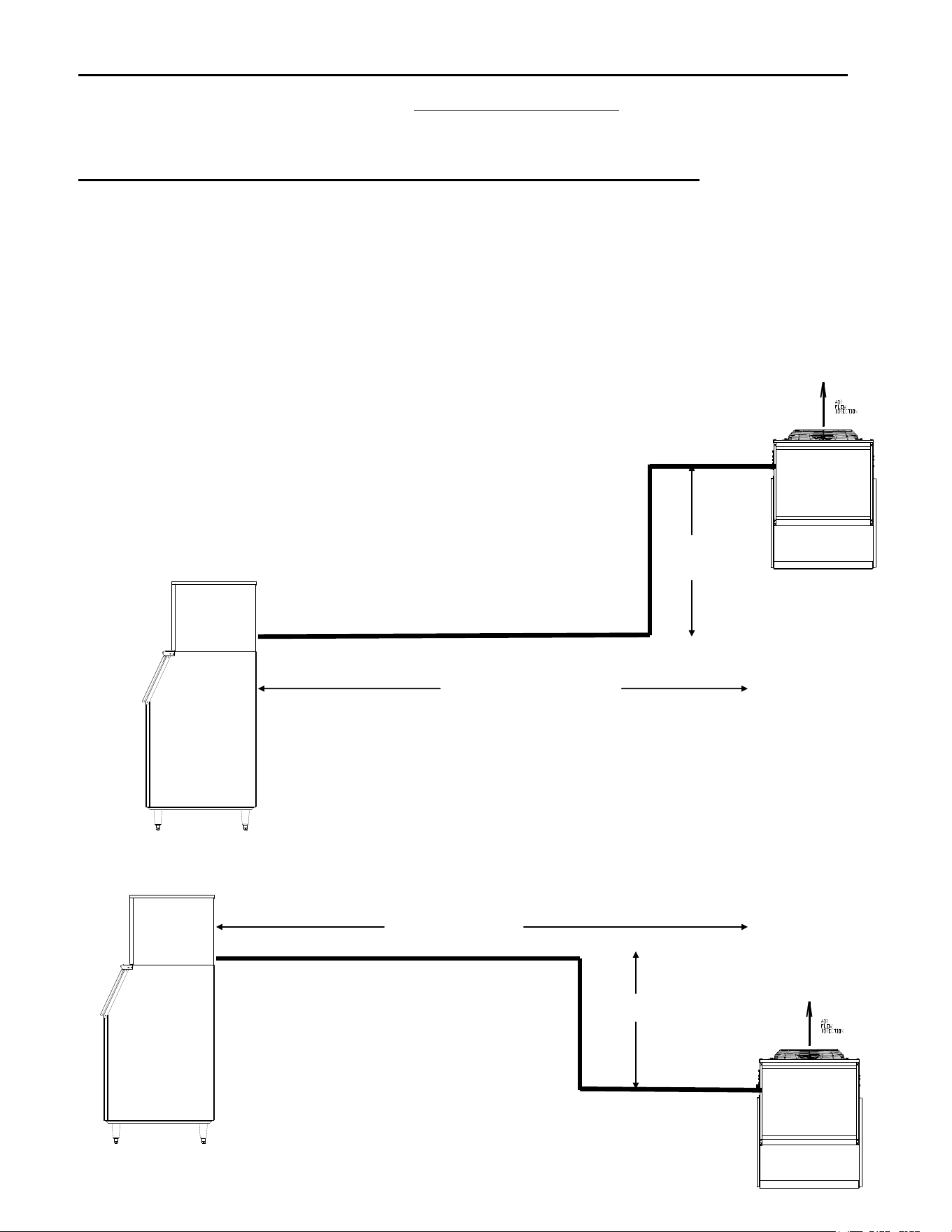
Location Limits: Remote condenser location must not exceed ANY of the following:
● Maximum rise from the ice machine to the remote condenser is 35 physical feet.
● Maximum drop from the ice machine to the remote condenser is 15 physical feet.
● Physical line set maximum length is 75 feet.
● Calculated line set length maximum is 100 feet.
● Ambient operating temperatures: -20°F (-28.9°C) to 120°F (48.9°C)
Calculation Formula
● Drop = dd x 6.6 (dd = distance in feet)
● Rise = rd x 1.7 (rd = distance in feet)
● Horizontal Run = hd x 1 (hd = distance in feet)
● Calculation: Drop(s) + Rise(s) + Horizontal Run = dd+rd+hd=Calculated Line Length
Configurations that do NOT meet these requirements must receive written authorization from
Ice-O-Matic. This includes multipass or rack system remote condensers.
Do NOT:
● Route a line set that rises, then falls, then rises.
● Route a line set that falls, then rises, then falls.
Remote Condenser Location:
Limited to a 25, 40, 45, 60 or a 75 foot length of precharged refrigerant tubing connecting the ice machine to the remote
condenser. The remote condenser must be above or level with the ice machine. Select the best available location,
protecting the remote condenser from extremes of dirt, dust and sun. Meet all applicable building codes. Usually the
services of a licensed electrician are required.
Roof Attachment:
1. Install and attach the remote condenser to the roof of the building, using the methods and practices of construction that
conform to the local building codes, including having a roofing contractor secure the remote condenser to the roof.
2. Have an electrician connect the remote condenser fan motor wires to the ice machine, using the junction box at the
back of the ice machine.
Precharged Line Set Routing
CAUTION: Do not connect the precharged tubing until all routing and forming of the tubing is complete. See the
coupling instructions for connecting information.
1. Each set of precharged tubing refrigerant lines consists of a 3/8 diameter liquid line and a 1/2 inch diameter discharge
line. Both ends of each line have quick connect couplings, one end has a Schrader valve connection which goes to the
condenser.
Note: The openings in the building ceiling or wall, listed in the next step, are the minimum sizes recommended for
passing the refrigerant lines through.
2. Have the roofing contractor cut a minimum hole for the refrigerant lines of 2.50 inch. Check local codes, a separate
hole may be required for the electrical power to the condenser.
CAUTION: DO NOT KINK OR CRIMP REFRIGERANT TUBING WHEN INSTALLING IT.
3. Route the refrigerant lines through the roof opening. Follow straight line routing whenever possible. Any excess tubing
MUST remain within the building.
4. Spiral the excess length of precharged tubing inside the building. Use a horizontal spiral to avoid any traps in the lines.
5. Have the roofing contractor seal the holes in the roof per local codes.
CAUTION: The couplings on the sets of precharged lines are self sealing when installed properly. Carefully
follow the instructions in the VRC manual.
ICE Series Remote Condenser Guidelines
Page 5
The following remote ice makers incorporate the
Umixing valve in the condenserU. This configuration allows up to a 100
foot calculated remote line set run. Reference the diagram below to calculate the maximum 100 foot line set run.
Maximum actual line set run is limited to 100 ft. Add ¼ ounce of refrigerant for each actual foot from 75 feet to 100
feet actual lineset run.
UICE Machine Model Number Remote Condenser Model Number
ICE2106/7R VRC5061B
ICE1806/7R VRC5061B
ICE1506HR VRC2661B
ICE1405/6/7R VRC2661B
ICE1006R VRC2061B
ICE0926R VRC2061B
ICE0806R VRC2061B
ICE0726R VRC2061B
ICE0606R VRC1061B
ICE0500R VRC1001B
Limitations for remote machines that have the mixing valve mounted in the condenser.
Maximum Rise is 35 feet.
Maximum Drop is 15 feet.
Maximum equivalent run is 100 feet.
Formula for figuring maximum equivalent run is as follows:
Rise x 1.7 + Drop x 6.6 + horizontal run = equivalent run.
Examples: 35 ft. rise x 1.7 + 40 ft. horizontal = 99.5 equivalent feet line run
35 ft. rise
40 ft. horizontal
10 ft. drop x 6.6 + 34 ft horizontal
= 100 equivalent feet line run
10 ft. dro
p
34 ft. horizontal
V
erify the ICE machine is compatible with the remote condenser. Some
ice machines and some remote condensers may or may not have a Mixing
Valve (Head Master). Only one valve is required per system. Kits are
available to modify the condenser for compatibility. For more information
contact your Ice-O-Matic Distributor.
ICE Series Electrical and Plumbing Requirements
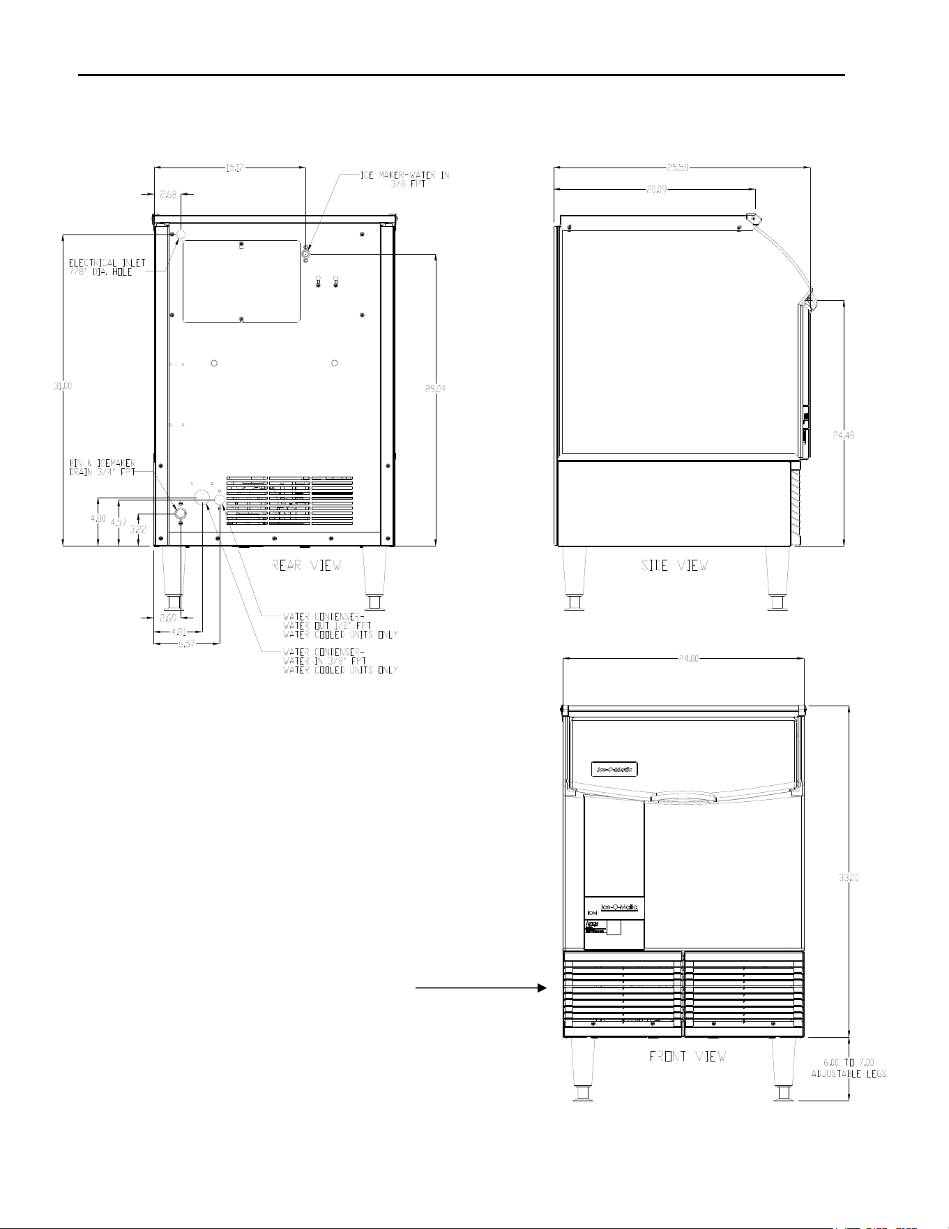
Page 6
Electrical and Plumbing Requirements: ICEU150, 220, 225 and 226
ON-OFF-WASH Switch is
located in the control box.
Remove the grill screws to
access the control box.
Note: The ICEU150, 220, 225 and 226
do not have a splash curtain.
These models utilize a thermostatic bin
control in place of a mechanical bin
switch.
ICE Series Electrical and Plumbing Requirements
Page 7
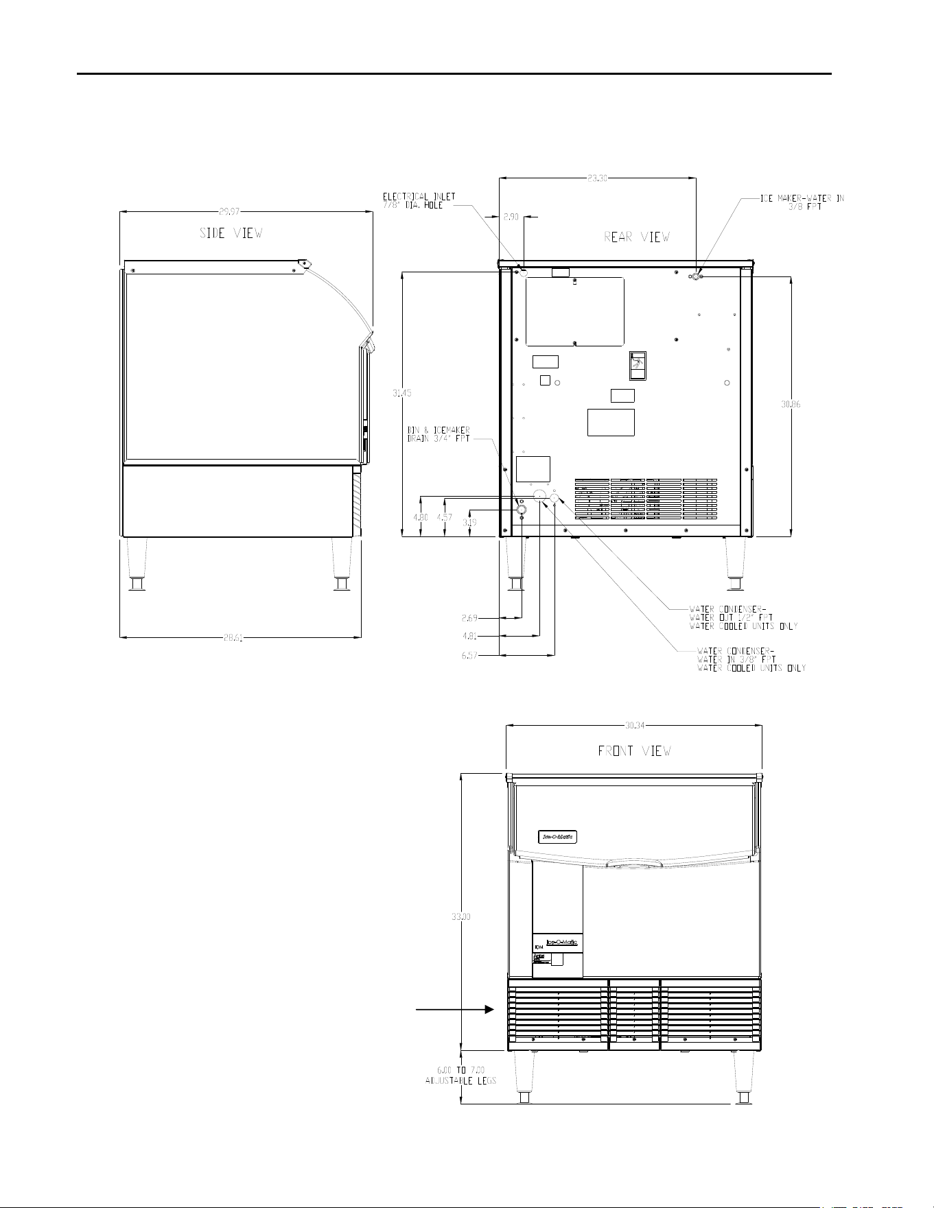
Electrical and Plumbing Requirements: ICEU300 and 305
Note: The ICEU300 and ICEU305 do not
have a splash curtain.
These models utilize a thermostatic bin
control in place of a mechanical bin
switch.
ON-OFF-WASH Switch is located in the
control box.
Remove the grill screws to access the
control box.
ICE Series Electrical and Plumbing Requirements
Page 8
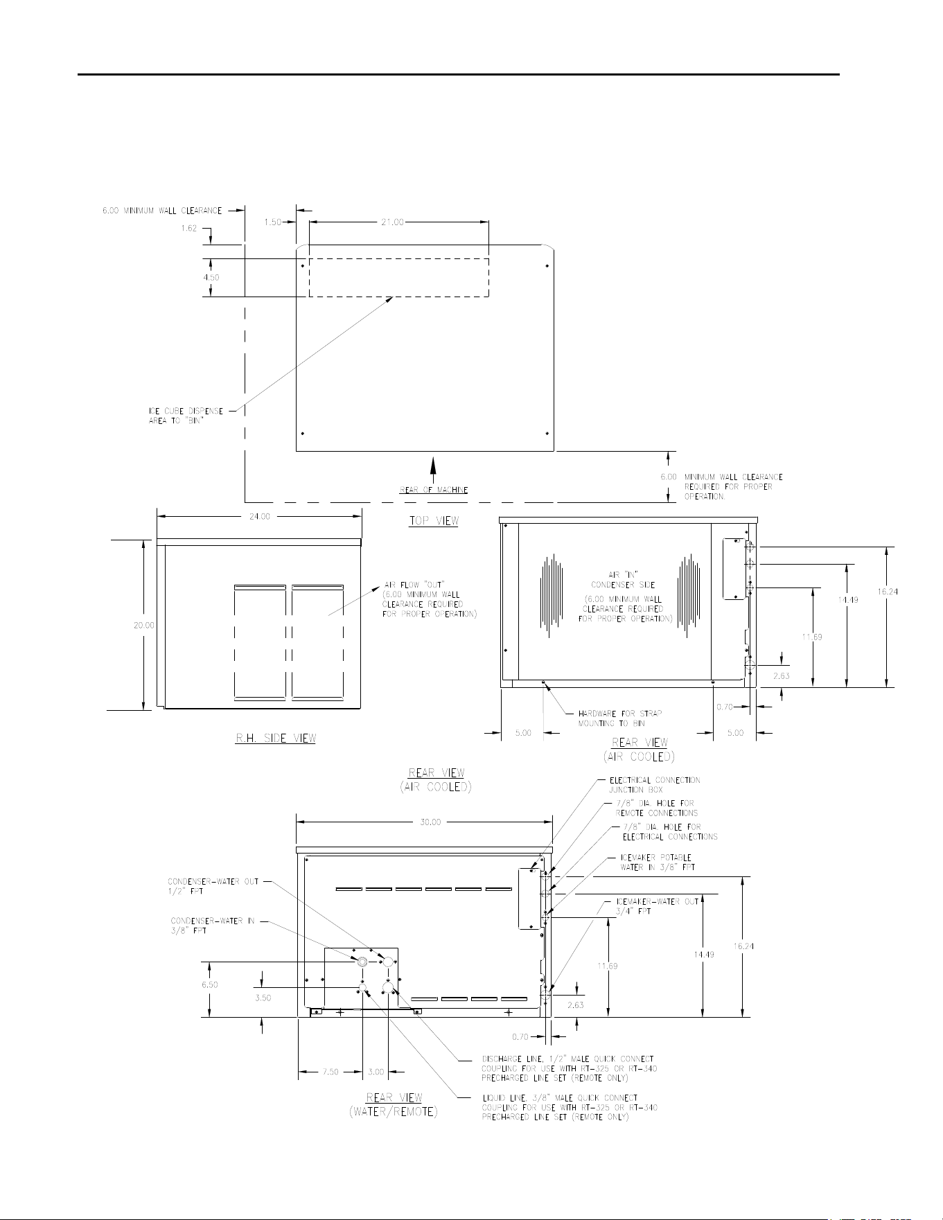
Electrical and Plumbing Requirements: ICE0250, ICE0305, ICE0400/5/6, ICE0500 and ICE0605/6
ICE Series Electrical and Plumbing Requirements
Page 9
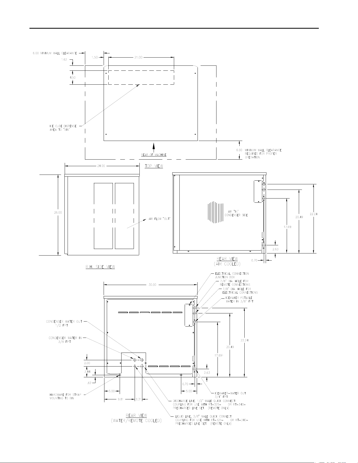
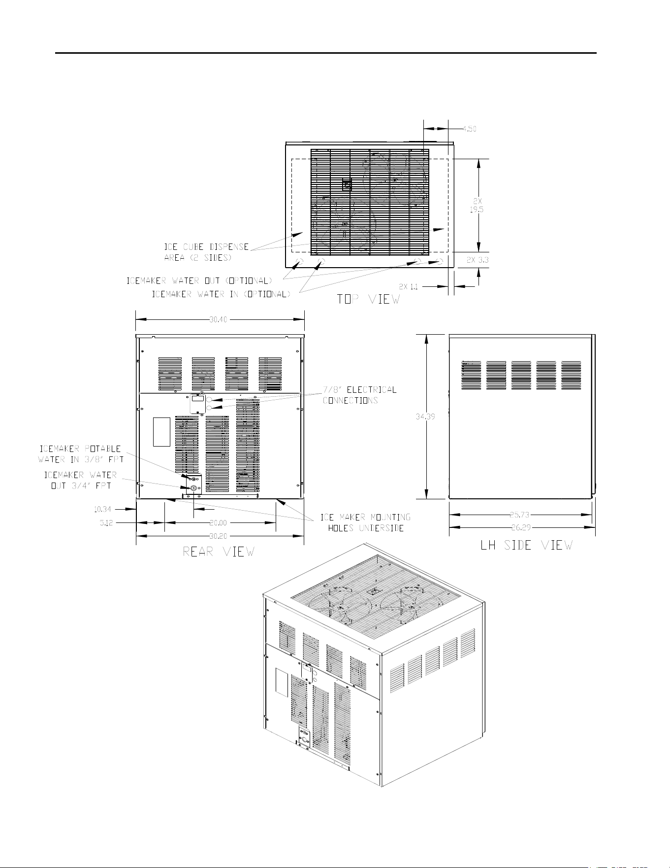
Electrical and Plumbing Requirements: ICE0805/6, ICE855/6GA and ICE1005/6/7
ICE Series Electrical and Plumbing Requirements
Page 10
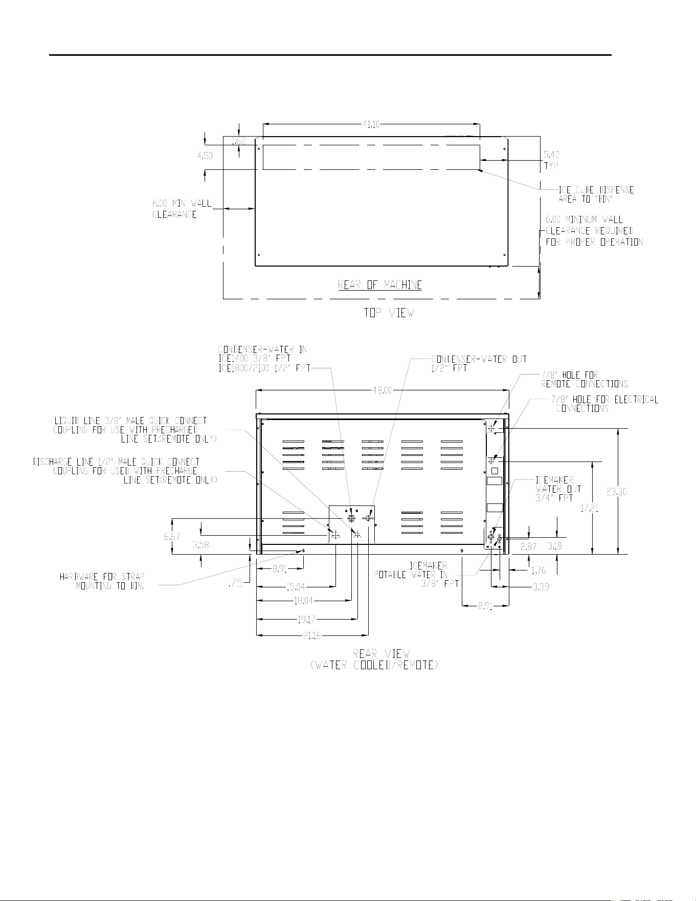
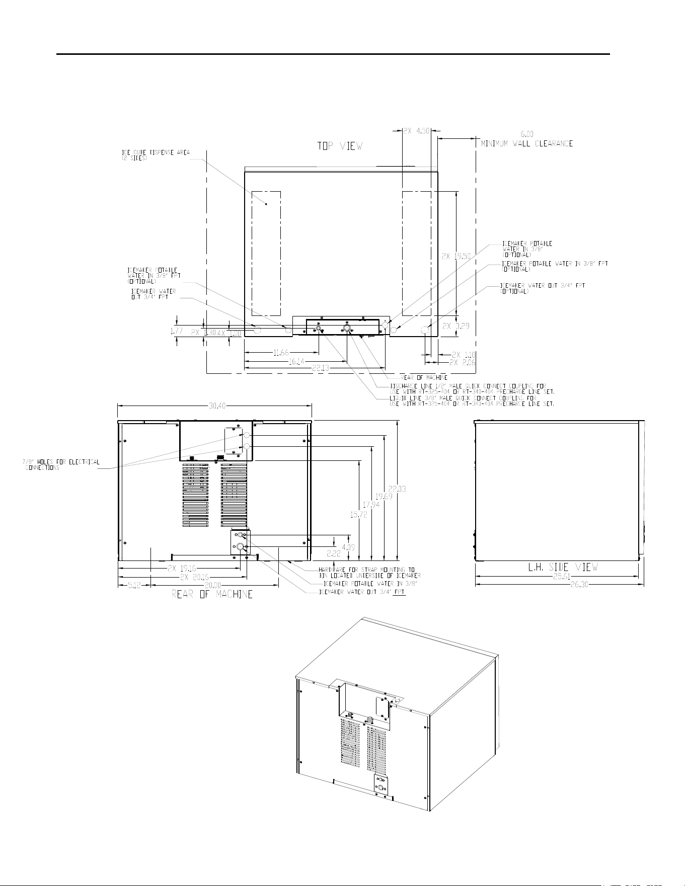
Electrical and Plumbing Requirements: ICE1405/6/7, ICE1806/7 and ICE2106/7
ICE Series Electrical and Plumbing Requirements
Page 11
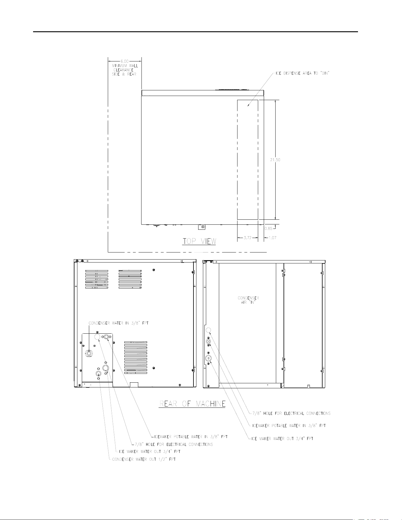
Electrical and Plumbing Requirements: ICE0320/5 and ICE0520/5
ICE Series Electrical and Plumbing Requirements
Page 12
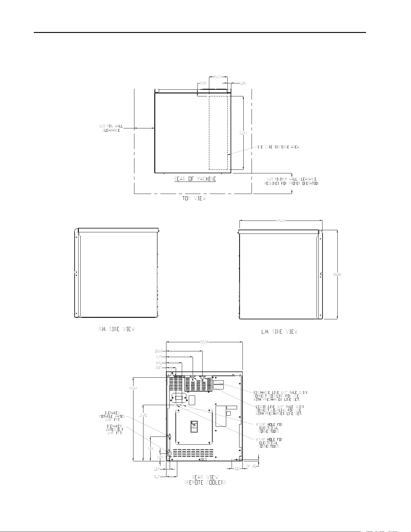
Electrical and Plumbing Requirements: ICE1506R5 Remote
ICE Series Electrical and Plumbing Requirements
Page 13
Electrical and Plumbing Requirements: ICE1506HT Air Cooled, Top Air Discharge
Clearance Requirements for the
ICE1506HT to insure proper air circulation.
Top 8 inches
Back 6 inches
Sides 2 inches
ICE Series Electrical and Plumbing Requirements
Page 14
Electrical and Plumbing Requirements: ICE0726 and ICE0926 Remote

ICE Series How the ICE Machine Works
Page 15
How the ICE Machine Works
A general description of how the ICE Series cubers works is given below. With the ICE/OFF/WASH switch in the ICE
position, the compressor, water pump and condenser fan motor (when applicable) will energize starting the freeze
cycle.
During the freeze cycle, water is circulated over the evaporator(s) where the ice cubes are formed. When the suction
pressure has pulled down to the proper cut-in pressure of the timer initiate (pressure control), the contacts will close
and energize the time delay module (timer). At this time, the cubes will be close to completion.
The remaining portion of the freeze cycle is determined by the timer setting. The timer is pre-set at the factory to
achieve the proper ice bridge thickness but may need to be adjusted upon initial start-up, see Page 14 for timer
adjustment.
The factory initial timer settings are 64 and 128 for the Half Cube and 128 and 256 for a Full Cube.
Once the amount of time on the timer has passed, the control relay will be energized and the machine will enter
harvest. Power is now supplied to the water purge valve, hot gas valve, and the harvest motor.
The water purge valve opens, and allows the water pump to purge the water remaining in the water trough, removing
impurities and sediment. This allows the machine to produce clear ice cubes and keep mineral build up at a minimum.
The hot gas solenoid opens allowing hot gas to go directly to the evaporator, heating the evaporator and breaking the
bond between the evaporator and the ice slab.
Note: The operation of the Hot Gas valve and Water Pump vary by model number, reference the wiring
diagram on the specific model number for operation sequence.
The harvest assist motor, which is also energized during harvest, turns a slip clutch, which pushes a probe against the
back of the ice slab. Once the evaporator has reached approximately 40F (4.5F) in temperature, the slip clutch
overcomes the bonding of the ice to the evaporator and pushes the slab of ice off of the evaporator and into the
storage bin.
The clutch also actuates a switch that rides on the outer edge of the clutch. When the clutch completes one
revolution, the switch is tripped and the machine enters the next freeze cycle.
Note: Units produced from July of 2015 utilize an improved drive motor which eliminated the clutch assembly.
When ice drops into a full bin during harvest, the splash curtain is held open which activates a bin switch shutting the
machine off. When ice is removed from the bin, the splash curtain will close and the machine will come back on.
Note: The ICEU150, 220, 225, 226, ICEU300 and 305 do not have a splash curtain. These models utilize a
thermostatic bin control in place of a mechanical bin switch.
ICE Series Start-Up Procedure
Page 16
Start-Up Procedure
Before starting the machine, make sure the machine is level within 1/8 inch in all directions, the bin or dispenser leg
height can be adjusted by rotating the leg foot.
Check the water level in the water trough. It should be approximately ½ inch above the top of the water pump impeller
housing. The water level can be adjusted by bending the float arm.
Move the ICE-OFF-WASH switch to the ICE position. The switch is located in the control box. Remove the ice machine
front panel or remove the lower grill on the under counter models to access the control box.
Check for proper water flow over the evaporator(s). There should be an even flow of water over the evaporator(s).
Check the water regulating valve (water cooled machine) for proper adjustment by measuring the discharge pressure
which should be adjusted to maintain 250 psi (17.01 bar / 1.723 MPa). Adjust the water regulating valve as required.
Water exiting the condenser should be between 100°F (38°C) and 110°F (43°C).
As ice begins to form on the evaporators, check the freeze pattern of the ice. Ice should form evenly across the
evaporator. Models ICE0800, 1000, 1800 and 2100 machines will have a slight variance from the top to the bottom of
the evaporator(s).
Bridge Thickness and Timer Adjustment
Oncetheunithasgonethrough1or2harvestcycles,verifythattheiceproductionisperthechartbelow.
BatchWeights
Models HalfCube FullCube
ICEU150,ICEU220,ICEU225,ICEU226,ICEU300,ICEU305,ICE0250,ICE0305,ICE0320,ICE0325
2.9‐3.2 3.2‐3.5
ICE0400,ICE0405,ICE0406,ICE0500,ICE0520,ICE0525,ICE0600,ICE0605,ICE0606
4.9‐5.2 5.5‐5.8
ICE1405,ICE1406,ICE1407,ICE1506
5.6‐6.0 6.4‐6.8
ICE0726,ICE0926,ICE0805,ICE0806,ICE1005,ICE1006,ICE1007,ICE1806,ICE1807,ICE2106,ICE2107
6.9‐7.4 7.9‐8.3
As a reference, when ice drops off the evaporator(s) during harvest, check the bridge thickness of the ice slab. The
bridge should be approximately 3/16 of an inch on Undercounter, ICE0250 and ICE0305 units. The bridge should be
approximately 1/8 of an inch on all other units. If the batch weight or bridge thickness is incorrect, the timer will need to
be adjusted.
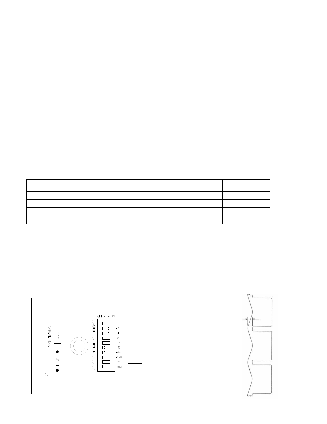
Both the Ice Batch Weight and Bridge Thickness are controlled by the freeze timer located in the control box. To check
the timer setting, add the seconds of each dipswitch turned to the “ON” position. The number beside the each
dipswitch represents seconds. To increase the Batch Weight and bridge thickness, increase the timer setting. To
decrease the Batch Weight and bridge thickness, decrease the timer setting. The freeze timer can be adjusted by
sliding one or more switches to either the “ON” or “OFF” position to obtain the desired setting.
Combine time in seconds
Timer shown is set for 31 seconds
Bridge
Thickness
ICE Series Start-Up Procedure
Page 17
Bin Control Operation
The bin control is used to shut the machine off when the bin fills with ice. The bin control must be checked upon
installation or initial start-up and when performing maintenance. Adjustments are not covered under warranty.
There is one bin switch for each evaporator. The actuator arm of the bin switch comes in contact with the splash
curtain. When the bin is full of ice, the splash curtain is held open when ice drops off of the evaporator. This releases
the pressure of the bin switch actuator arm allowing the switch to open.
Single evaporator machines: (Including the ICE1506R) If the bin switch opens during freeze or the first part of
harvest, relay 2 bypasses the bin switch and the machine will continue running. If the bin switch is opened during
harvest when the cam switch is lifted onto the high part of the cam, the machine will shut off. When the bin switch
closes again, the machine will restart.
Dual evaporator machines: If either bin switch opens during the freeze cycle, the machine will shut off. Relay 1 and
relay 2 will bypass the bin switches during defrost. If either bin switch is open when the machine returns to the freeze
cycle, the machine will shut off.
Undercounter machines: A thermostatic bin control is used on the undercounter
models. The bin thermostat is located in the control box with a capillary tube,
which is in a brass thermo-well mounted to the right side of the water trough.
When ice comes in contact with the capillary tube thermo-well, the bin thermostat
opens and the machine will shut off.
Bin Control Adjustment
All Models (Except Undercounter Models): Check the bin switch for proper
adjustment by swinging the bottom of the curtain away from the evaporator.
Slowly bring the curtain towards the evaporator. The switch should close when
the bottom edge of the curtain is even with the outer edge of the water trough.
Adjust the switch by loosening the nuts that hold the switch in place. Move the
switch to the proper position and retighten the nuts. Recheck the adjustment.
Adjustments are not covered under warranty.
Undercounter Models and ICE1506R
The Bin Thermostat used on these Self Contained Ice Cuber Machines is a
sensitive device influenced by ambient conditions including altitude and
temperature. The machine is set up to operate properly at the factory for 70°F at
sea level. If your ice machine shuts off early, bin half full, or doesn’t shut off, bin
overflowing, please follow these instructions to set the bin thermostat.
1. These instructions are best followed on a full ice bin with at least 3 inches
of ice resting against the brass thermal well. The machine must be
running to perform this adjustment; follow step two if the machine is off.
2. Turn the thermostat adjustment screw clockwise until it stops; this is the
max cold setting and will prevent the machine from shutting off.
3. Hold a minimum of 3 inches of ice against the middle of the brass thermal
well for 3-4 minutes. It is imperative that enough ice be used for the
prescribed time to properly cool the
thermostat.
4. Slowly turn the adjustment screw counter-
clockwise until the machine shuts off. If
the screw is turned too quickly, the
thermostat could be set to too warm a
temperature. Turn slowly.
5. Remove the ice from the well and warm
the brass with your hand; the machine
should turn back on.
The ice machine is now set for ambient
conditions. If the ice machine location
experiences significant changes in ambient
temperatures, this procedure will need to be
followed again. Adjustments are not covered
under warranty.
The bin switch
contacts must be
closed when the
bottom edge of
the curtain is
flush with the
edge of the
water trough
Eva
p
orator
S
p
lash Curtain
Bin Switch
Adjustment
Nuts
Thermal -well
Thermostatic
Bin Control

ICE Series General Maintenance
Page 18
Electrical shock and/or injury from moving parts inside this machine can cause serious injury. Disconnect electrical
supply to machine prior to performing any adjustments or repairs.
Failure to perform the required maintenance at the frequency specified will void warranty coverage in the event of a
related failure.
General Maintenance Procedure
To insure economical, trouble free operation of your machine, it is recommended that the following maintenance be
performed every 6 months.
1. Clean the ice-making section per the instructions below. Cleaning should be performed a minimum of every 6
months. Local water conditions may require that cleaning be performed more often.
2. Check ice bridge thickness. See page 16 for proper thickness and adjustment procedure.
3. Check water level in trough. See page 16 for proper water level and adjustment.
4. Clean the condenser (air-cooled machines) to insure unobstructed air flow.
5. Check for leaks of any kind: Water, Refrigerant, Oil, Etc.
6. Check the bin control switch for proper adjustment. See page 17 for bin switch adjustment.
7. Check the water regulating valve (water cooled machine) for proper adjustment by measuring the discharge
pressure which should be adjusted to maintain 250 psi (17.01 bar / 1.723 MPa). Adjust the water regulating valve
as required. Water exiting the condenser should be between 100°F (38°C) and 110°F (43°C).
8. Check all electrical connections.
9. Oil the fan motor if the motor has an oil fitting. (Self contained air-cooled models only)
10. Check the water filter (if applicable) and replace if dirty or restricted.
11. Inspect the evaporator water distribution tube to insure even distribution of water across the face of the evaporator.

ICE Series Cleaning/Sanitizing Procedures
Page 19
ICE Machine and/or Bin/Dispenser Cleaning and Sanitizing Instructions
Cleaning should be scheduled at a minimum of twice per year.
Sanitizing should be performed after each cleaning or more frequently as required.
Note: Electrical power will be ON when performing the following cleaning instructions.
The cleaning and sanitizing of any commercial ice machine are important procedures all operators need to have in
their preventive maintenance protocol. While similar, these two procedures are uniquely different and accomplish
different things. Cleaning or de-liming, dissolves the mineral deposits on the evaporator and removes scale, calcium
and other mineral buildup. Sanitizing disinfects the machine and removes microbial growth including mold and slime.
In either case, it is important to use solutions that do not harm the ice machine. Never use cleaning or sanitizing
solutions that contain Nitric Acid, Sulfuric Acid, Hydrochloric Acid, Carbolic Acid, Acetic Acid, diluted Acetic Acid or
non-food-grade vinegar (concentration of acetic acid greater than 6% and does not contain enzymes created in
processing) or any chlorine-based solution such as bleach, chlorine dioxide or any type of salts such as potassium
chloride (potassium salts) or sodium chloride. Check the label or the manufacturer’s Material Safety Data Sheet
(MSDS) to be sure. These chemicals can attack the surface of the evaporator as well as other metal components
causing corrosion and flaking. Reverse Osmosis (RO) water can be very acidic and can attack the evaporator and
other metal in the ice machine. Because the RO process removes all minerals and metals from the water it can
promote the faster growth of microbial, mold and slime. If RO water is used, Ice-O-Matic recommends the water pH is
verified to be a neutral 7.0 to minimize the corrosive effects. Incorrect cleaners, sanitizers, and RO water that does not
have a neutral pH could void the machine’s warranty.
Cleaning
Prior to Cleaning the ice machine and/or Bin/Dispenser, perform the following:
1. Remove the ice machine front panel.
2. Make sure that all the ice is off of the evaporator. If ice is being made, wait for cycle completion then turn the
machine “OFF” at the ICE/OFF/WASH selector switch.
3. Turn off the potable water supply to the ice machine.
4. Remove all ice in the storage bin. (Required for cleaning and/or sanitizing)
Cleaning Instructions-Ice Machine
1. Initiate the wash cycle at the ICE/OFF/WASH switch by placing the switch in the “WASH” position. Depress the
Purge Switch to flush the remaining water from the water trough. Release the Purge Switch when the water
trough is empty
2. Terminate the wash cycle at the ICE/OFF/WASH switch by placing the switch in the “OFF” position.
3. Add recommended amount of approved nickel safe ice machine cleaner (diluted per manufacturer’s instructions) to
the water trough. (Reference cleaner Manufacturer’s instructions on the package)
4. Initiate the wash cycle at the ICE/OFF/WASH switch by placing the switch in the “WASH” position. Allow the
cleaner to circulate for approximately 15 minutes to remove mineral deposits.
5. Depress the Purge Switch and hold until the ice machine cleaner has been flushed down the drain
4. Terminate the wash cycle at the ICE/OFF/WASH switch by placing the switch in the “OFF” position. Remove the
splash curtain and inspect the evaporator and water spillway to ensure all mineral residue has been removed.
5. If necessary, wipe the evaporator, spillway and other water transport surfaces with a clean soft cloth to remove any
remaining residue. If necessary, remove and clean the water trough thoroughly to remove all scale or slime build-
up, remove the water distribution tube, disassemble and clean with a bottlebrush. Reassemble all components and
repeat steps 2 through 5 as required to remove any remaining residue.
7. Sanitizing the Ice Machine is required after cleaning per Sanitizing Instructions
Cleaning Instructions-Storage Bin/ Dispenser
1. Open the bin door and remove all of the ice in the storage bin, store the ice in a clean container for reuse or discard.
2. Add recommended amount of approved nickel safe ice machine cleaner (diluted per manufacturer’s instructions)
(Reference cleaner Manufacturer’s instructions on the package)
3. Thoroughly wash all surfaces within the bin, this includes the bin door, bin walls, window track and snout area with
soap and water and rinse. Note: An extended handle soft bristle brush may be required.
4. Allow the mineral deposits to absorb the cleaner for approximately 15 minutes to remove and loosen the mineral
deposits. Note: This includes the bin drain.
5. Thoroughly wash all surfaces within the bin, this includes the bin door, bin walls, window track and snout area with
soap and water and rinse. Note: Repeat Steps 3, 4 and 5 as required.
6. Sanitizing the Storage Bin/Dispenser is required after cleaning per Sanitizing Instructions .
ICE Series Cleaning/Sanitizing Procedures
Page 20
Sanitizing
Prior to Sanitizing the ice machine and/or Bin/Dispenser, perform the following:
1. Remove the ice machine front panel.
2. Make sure that all the ice is off of the evaporator. If ice is being made, wait for cycle completion then turn the
machine “OFF” at the ICE/OFF/WASH selector switch.
3. Turn OFF the potable water supply to the ice machine.
4. Remove all ice in the storage bin. (Required for cleaning and/or sanitizing)
Sanitizing Instructions-Ice Machine
1. Use an EPA approved food equipment sanitizer at the solution mix recommended by the sanitizer manufacturer.
2. Add enough sanitizing solution to fill the water trough to overflowing and place the ICE/OFF/WASH switch to the
“WASH” position and allow circulation to occur for 10 minutes and inspect water transport system for water leaks.
During this time, wipe down all other ice machine splash areas. Inspect to insure that water transport system
components are in the correct position.
3. Depress the Purge Switch and hold until sanitizer has been flushed down the drain. Turn ON the ice machine
potable water supply and to flush the remaining diluted sanitizing solution out of the water trough for another 1 to 2
minutes.
4 Place the ICE/OFF/WASH switch to the “ICE” position and replace the front panel.
5. Discard the first two ice harvests. DO NOT USE any ice produced from the cleaning solution.
Sanitizing Instructions- Bin/ Dispenser
1. Use an EPA approved food equipment sanitizer at the solution mix recommended by the sanitizer manufacturer.
2. Sanitize the bin interior, this includes the bin door, bin walls, window track and snout area with an approved sanitizer
using the directions for that sanitizer. Note: This includes the bin drain.
3. Discard the first two ice harvests. DO NOT USE any ice produced from the cleaning solution.
Common Questions
•Ice-O-Matic Ice Machine/Bin Cleaning
Cleaning or de-liming an ice machine refers to the process of removing mineral buildup and scale from the evaporator
and other components. Ice-O-Matic recommends cleaning the ice machine at least every 6 months. More frequent
cleaning may be needed depending on water quality and filtration system used. It is the responsibility of the operator to
determine the optimal frequency for their particular environment. Cleaning will not remove microbial, mold, or slime.
The machine should always be sanitized after cleaning.
Ice-O-Matic recommends a “nickel-safe” cleaner such as Nu-Calgon or equivalent. Typically the chemical composition
is as follows:
Water 53% to 82%
Phosphoric Acid 15% to 40%
Citric Acid 3% to 7%
Ice-O-Matic recommends cleaning be done by a trained technician and that they follow detailed steps as prescribed in
the Technical Service Manual.
Most cleaners list in their instructions an ounces to a gallon mixture for proper level of solution. Pouring undiluted
cleaner directly into the water trough may not give proper dilution level. Ice-O-Matic recommends mixing in a plastic
container before pouring into trough.
•Ice-O-Matic Ice Machine/Bin/Dispenser Sanitizing
Ice-O-Matic recommends sanitizing or disinfecting an ice maker a minimum of every six months. More frequent
sanitizing may be needed if the machine is in a high yeast environment or if RO water is being used. It is the
responsibility of the operator to determine the optimal frequency for their particular environment.
Ice-O-Matic recommends an EPA approved sanitizer such as Nu-Calgon IMS-II or equivalent. Sanitizing is a simple
matter of running the EPA approved sanitizer through the ice machine/bin/dispenser and wiping down surfaces with
the sanitizer.
If being done at the same time as the cleaning process, sanitizing must be done after the cleaning process. Follow the
process as prescribed in the Owner’s Manual.
Note: this process requires the ice be removed from the bin.
Ice Machine Cleaner contains acids.
KEEP OUT OF THE REACH OF CHILDREN
Refer to ice machine cleaner manufactures emergency
instructions on container label.

ICE Series Cabinet Care
Page 21
Cleaning Stainless Steel and Aluminum
Commercial grades of stainless steel and aluminum are susceptible to rusting and corrosion if not properly maintained.
It is important that you properly care for the stainless steel and aluminum surfaces of your ice machine and bin to avoid
the possibility of rust or corrosion. Use the following recommended guidelines for keeping your machine looking like
new:
1. Clean the stainless steel and aluminum thoroughly once a week. Clean frequently to avoid build-up of hard,
stubborn stains. Also, hard water stains left to sit can weaken the metals corrosion resistance and lead to rust or
corrosion. Use a nonabrasive cloth or sponge, working with, not across, the grain.
2. Don't use abrasive tools to clean the metal surface. Do not use steel wool, abrasive sponge pads, wire brushes
or scrapers to clean the metal.
3. Don't use cleaners that use chlorine or chlorides. Do not use chlorine bleach products to clean the metal
surfaces. Chlorides break down the metals protective layer.
4. Rinse with clean water. If chlorinated cleansers are used, you must thoroughly rinse the surface with clean water
and wipe dry immediately.
5. Use the right cleaning agent. The table below lists the recommended cleaning agents for common metal cleaning
problems:
Cleaning Activity Cleaning Agent Method of Application
Routine cleaning Mild dish Soap, Ammonia, Glass Apply with a clean cloth
Cleaner, or mild detergent with water. or sponge. Rinse with
Household Kitchen clean water and wipe dry.
Cleaning chemicals approved
For metal surfaces
Removing grease or Oven cleaners. Apply generously, allow
fatty acids to stand for 15-20 minutes.
Rinse with clean water.
Repeat as required.
Removing hard water spots Vinegar Swab or wipe with clean cloth.
and scale. Rinse with clean water and dry.
ICE Series Winterizing Procedure
Page 22
Winterizing Procedures
Important!
Whenever the ice machine is taken out of operation during the winter months, the procedure below must be
performed. Failure to do so may cause serious damage and will void all warranties.
1. Turn off water to machine.
2. Make sure all ice is off of the evaporator(s). If ice is being made, initiate harvest or wait for cycle completion.
3. Place the ICE/OFF/WASH switch to the “OFF” position. The switch is located in the control box.
4. Disconnect the tubing between the water pump discharge and water distribution tube.
5. Drain the water system completely.
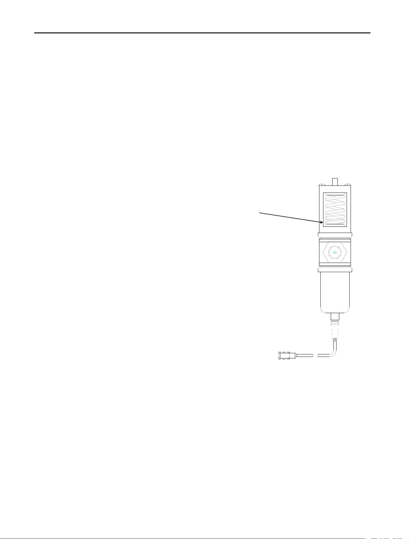
6. On water cooled machines, hold the water regulating valve open by
prying upward on the water valve spring with a screwdriver while
using compressed air to blow all the water out of the condenser.
7. Remove all of the ice in the storage bin and discard.

ICE Series Service History
Page 23
Service History
Model Number__________________Serial Number__________________Date Installed__________
__________________________________________________________________________________________
__________________________________________________________________________________________
__________________________________________________________________________________________
__________________________________________________________________________________________
__________________________________________________________________________________________
__________________________________________________________________________________________
__________________________________________________________________________________________
__________________________________________________________________________________________
__________________________________________________________________________________________
__________________________________________________________________________________________
__________________________________________________________________________________________
__________________________________________________________________________________________
__________________________________________________________________________________________
__________________________________________________________________________________________
__________________________________________________________________________________________
__________________________________________________________________________________________
__________________________________________________________________________________________
__________________________________________________________________________________________
__________________________________________________________________________________________
__________________________________________________________________________________________
__________________________________________________________________________________________
__________________________________________________________________________________________
__________________________________________________________________________________________
__________________________________________________________________________________________
__________________________________________________________________________________________
__________________________________________________________________________________________
__________________________________________________________________________________________
__________________________________________________________________________________________
__________________________________________________________________________________________
__________________________________________________________________________________________
__________________________________________________________________________________________
__________________________________________________________________________________________
__________________________________________________________________________________________
__________________________________________________________________________________________
__________________________________________________________________________________________
__________________________________________________________________________________________
__________________________________________________________________________________________
__________________________________________________________________________________________
__________________________________________________________________________________________
__________________________________________________________________________________________
__________________________________________________________________________________________
__________________________________________________________________________________________
__________________________________________________________________________________________
__________________________________________________________________________________________
__________________________________________________________________________________________
__________________________________________________________________________________________
__________________________________________________________________________________________
__________________________________________________________________________________________
__________________________________________________________________________________________
__________________________________________________________________________________________
__________________________________________________________________________________________
__________________________________________________________________________________________