Technical Support and E-Warranty Certificate www.vevor.com/support
DOOR CLOSER
MODEL:D4015 / D4016
We continue to be committed to provide you tools with competitive price.
"Save Half", "Half Price" or any other similar expressions used by us only represents an
estimate of savings you might benefit from buying certain tools with us compared to the major
top brands and does not necessarily mean to cover all categories of tools offered by us. You
are kindly reminded to verify carefully when you are placing an order with us if you are
actually saving half in comparison with the top major brands.

- 1 -
MODEL: D4015 / D4016
Have product questions? Need technical support? Please feel free to
contact us:
Technical Support and E-Warranty Certificate
www.vevor.com/support
NEED HELP? CONTACT US!
This is the original instruction, please read all manual instructions
carefully before operating. VEVOR reserves a clear interpretation of our
user manual. The appearance of the product shall be subject to the
product you received. Please forgive us that we won't inform you again if
there are any technology or software updates on our product.
DOOR CLOSER

- 2 -
WARNING:
1.Do not allow children to climb on the unit.
2. Keep children and pets away during assembly.
ASSEMBLY PRECAUTIONS
1. Please assemble the product in strict accordance with the instructions.
Incorrect assembly could be hazardous.
2. Please wear safety goggles and work gloves properly during assembly.
3. Do not try to assemble the product when feeling tired or when under the
influence of alcohol, drugs or medication.
4. Load bearing capacity and other product parameters are applied to the
properly and completely assembled product only.
5. Separate and count all parts and hardware.
6. Prepare the following tool: Philips Head Screwdriver.
7. If using power tools, please be careful to slow down and stop when
needed.
8. Two people are required for assembly.
9. Follow the intended uses only.
10.Use on stable surfaces only.
11. Regularly inspect for signs of wear, damage, or loose parts.
SAVE THESE INSTRUCTIONS
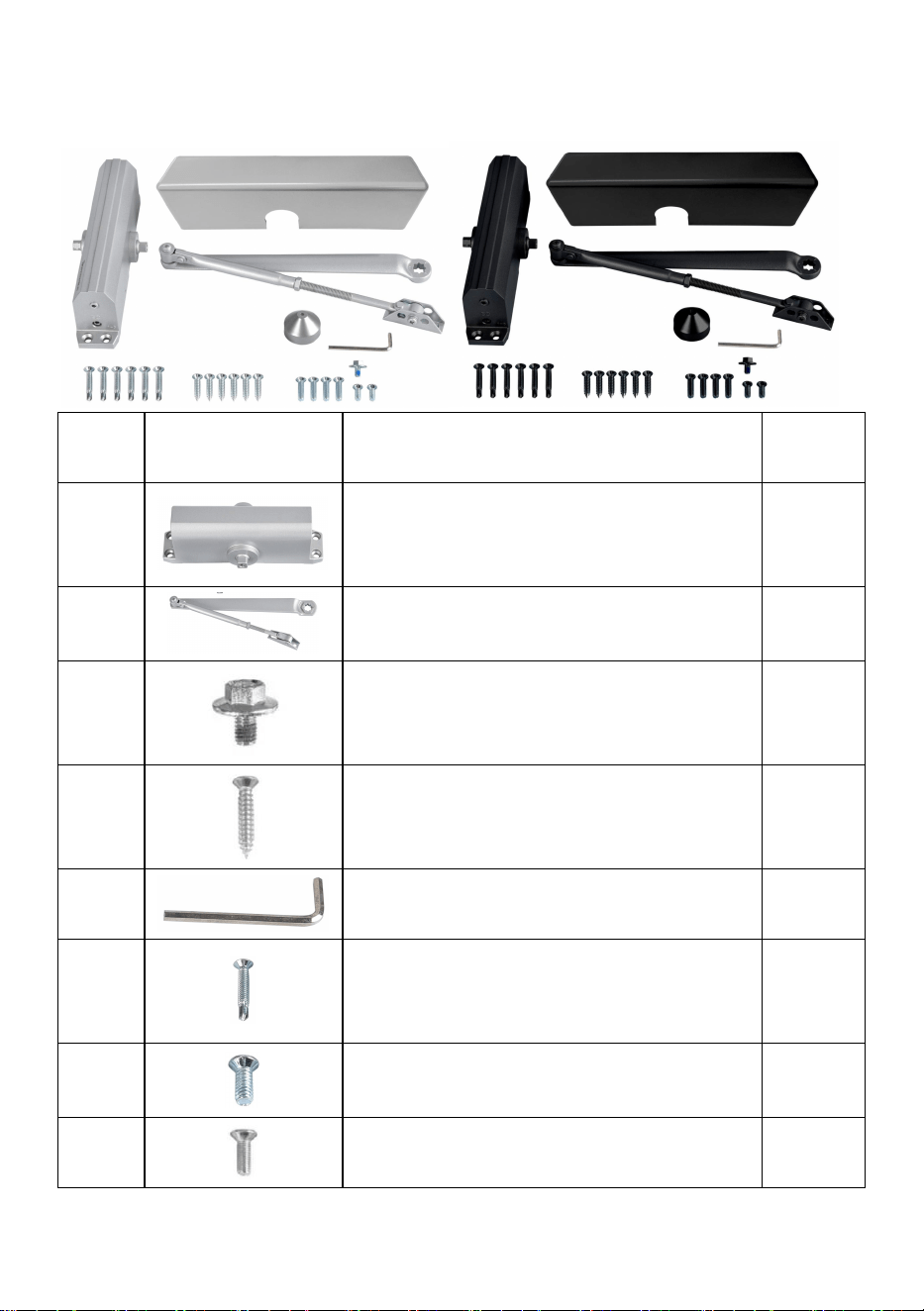
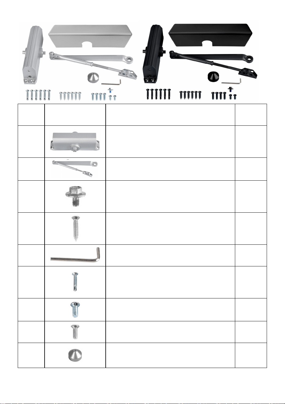
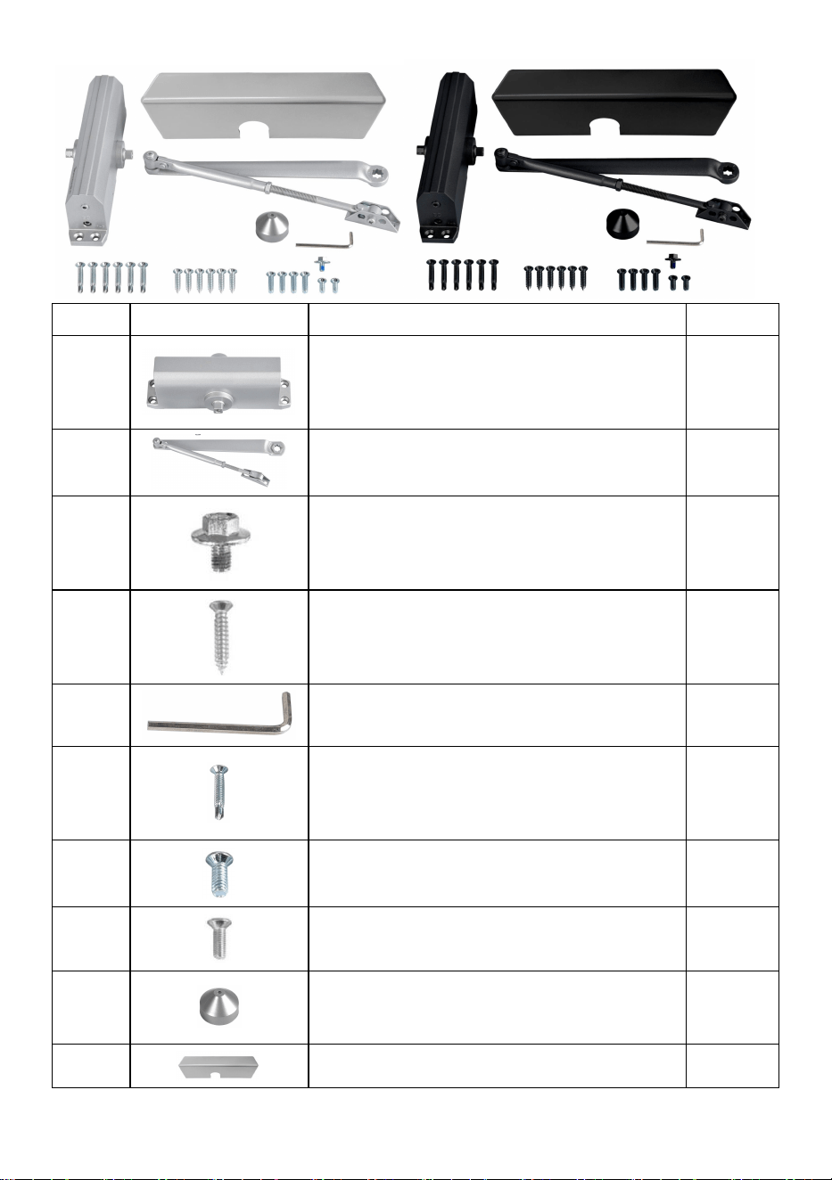
PART LIST
When unpacking this product, check to make sure the parts listed below
are included and carefully inspect for any damage that may have occurred
during transit. If any part is missing or damaged, do not attempt to
assemble or use the product.

- 3 -
NO
PICTURE
PART NAME
QTY
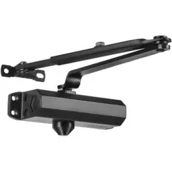
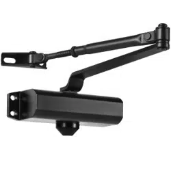
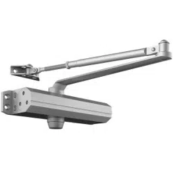
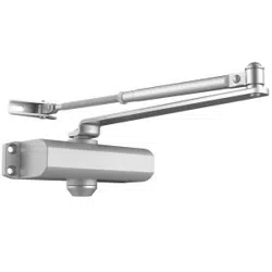
A
Door closer body
1
B
HO Arm
1
C
Rocker Arm Bolt M6×10
1
D
Wooden Doors Screw ST6.3×30
6
E
Hex Wrench
1
F
Self-tapping Screw ST6.3×38
6
G
Metal Doors Screw 1/4-20×16
2
H
Metal Doors Screw 1/4-20×25
4
I
Pinion Cap
1
J
Plastic Cover
1

- 4 -
PRODUCT PAREMETERS
Model
D4015
D4016
Material
Aluminum
Aluminum
Color
Silvery or Black
Silvery or Black
Door Max Load To
Use
265 lbs
330 lbs
INSTALLATION AND OPERATION INSTRUCTIONS
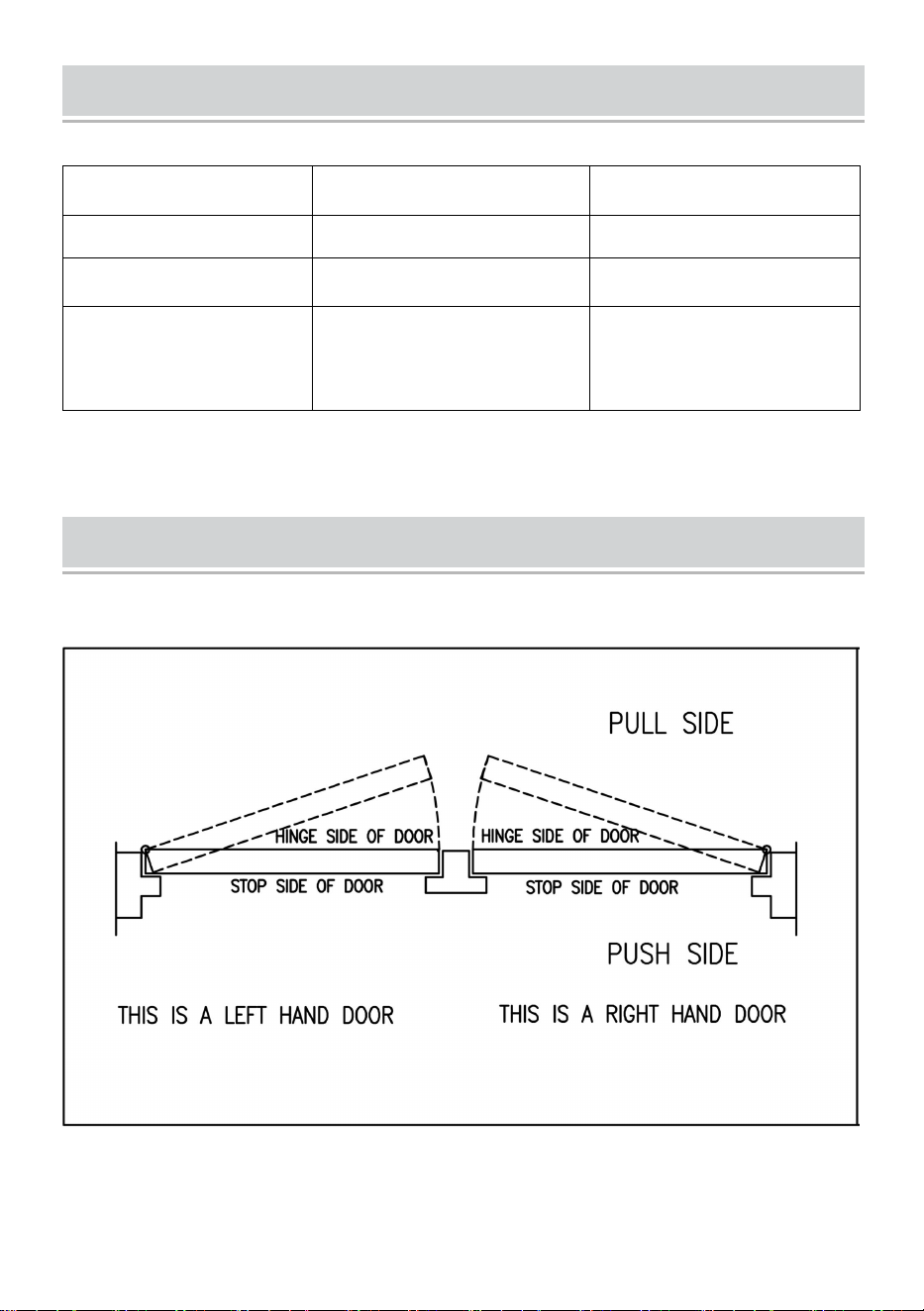
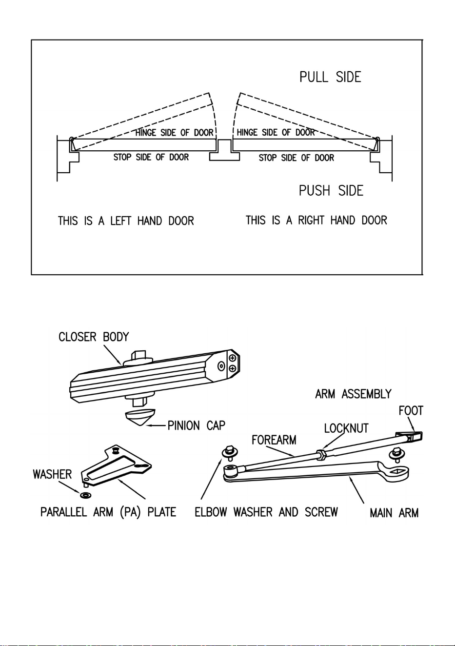
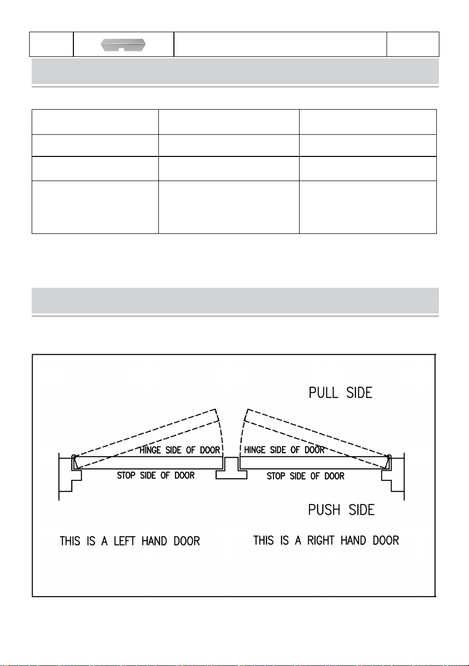
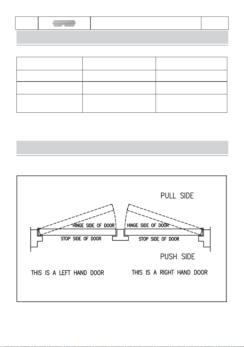
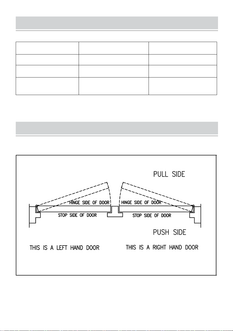
1.Chart to determine hand of door.
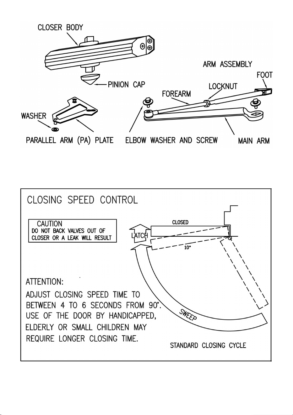
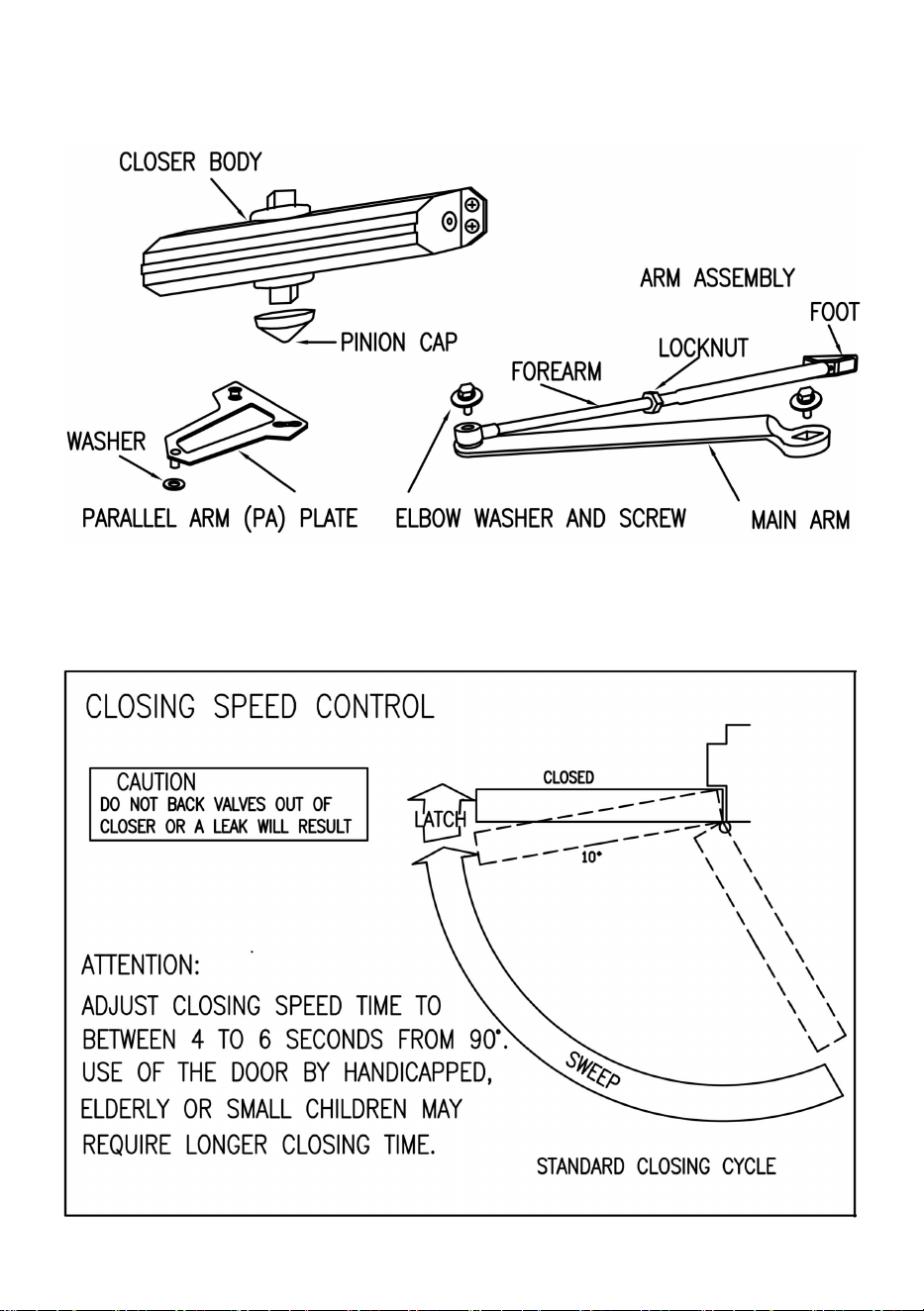
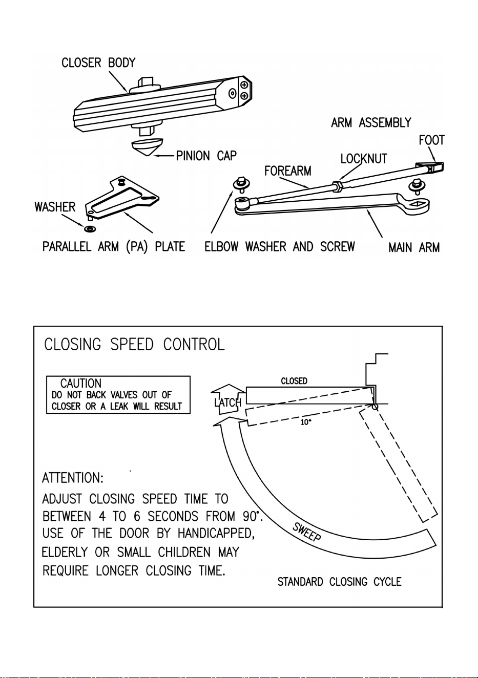
2.Components.
- 5 -
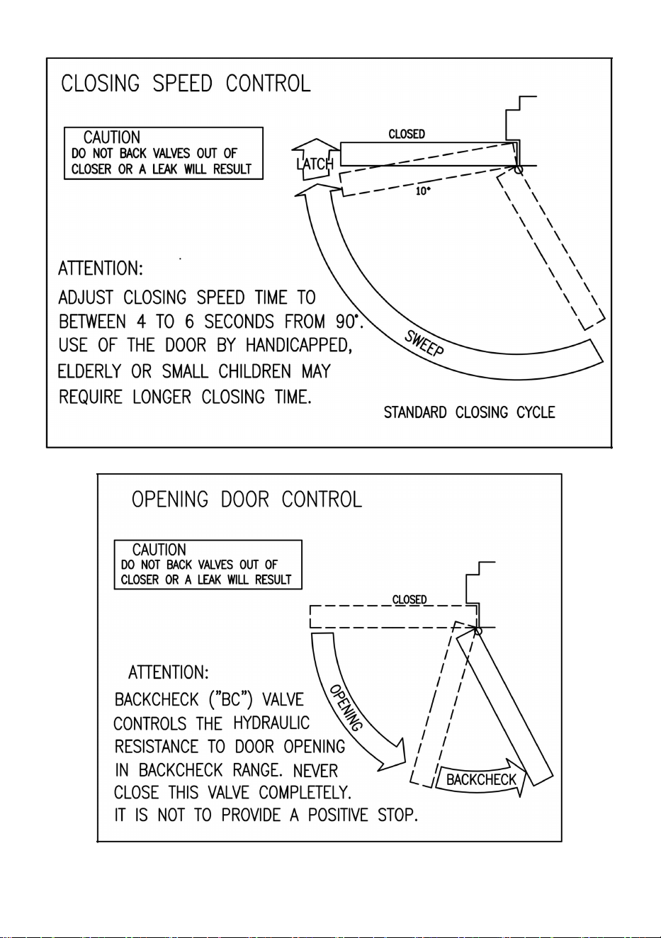
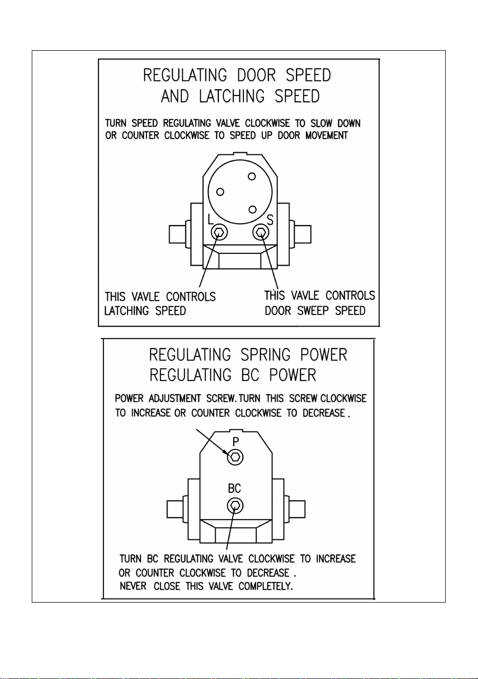
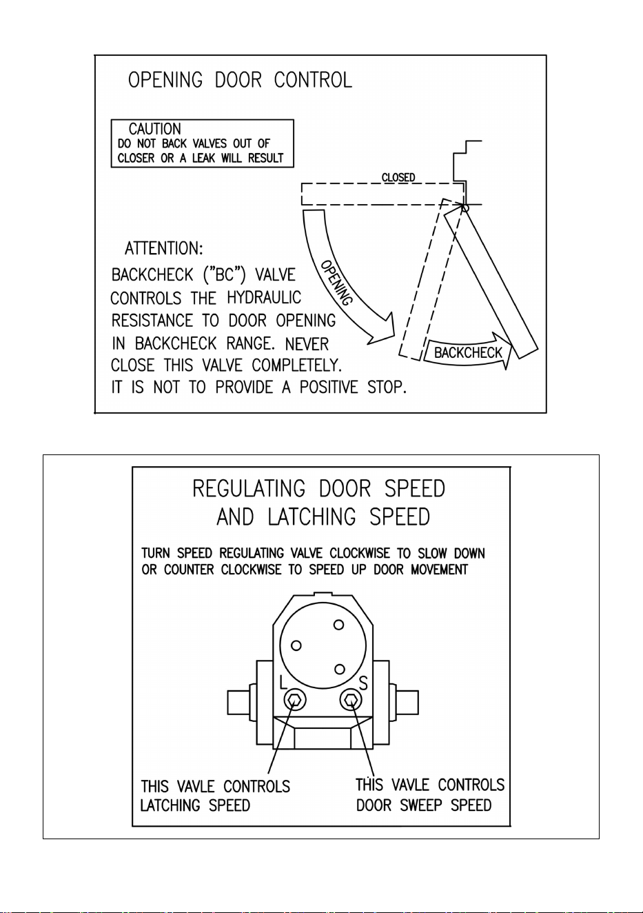
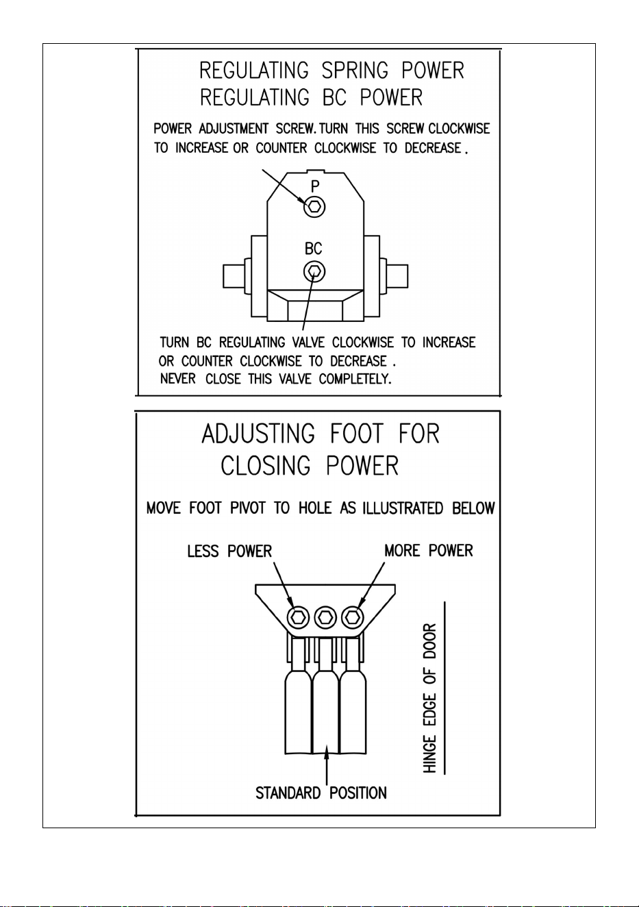
3.Control Function.

- 6 -
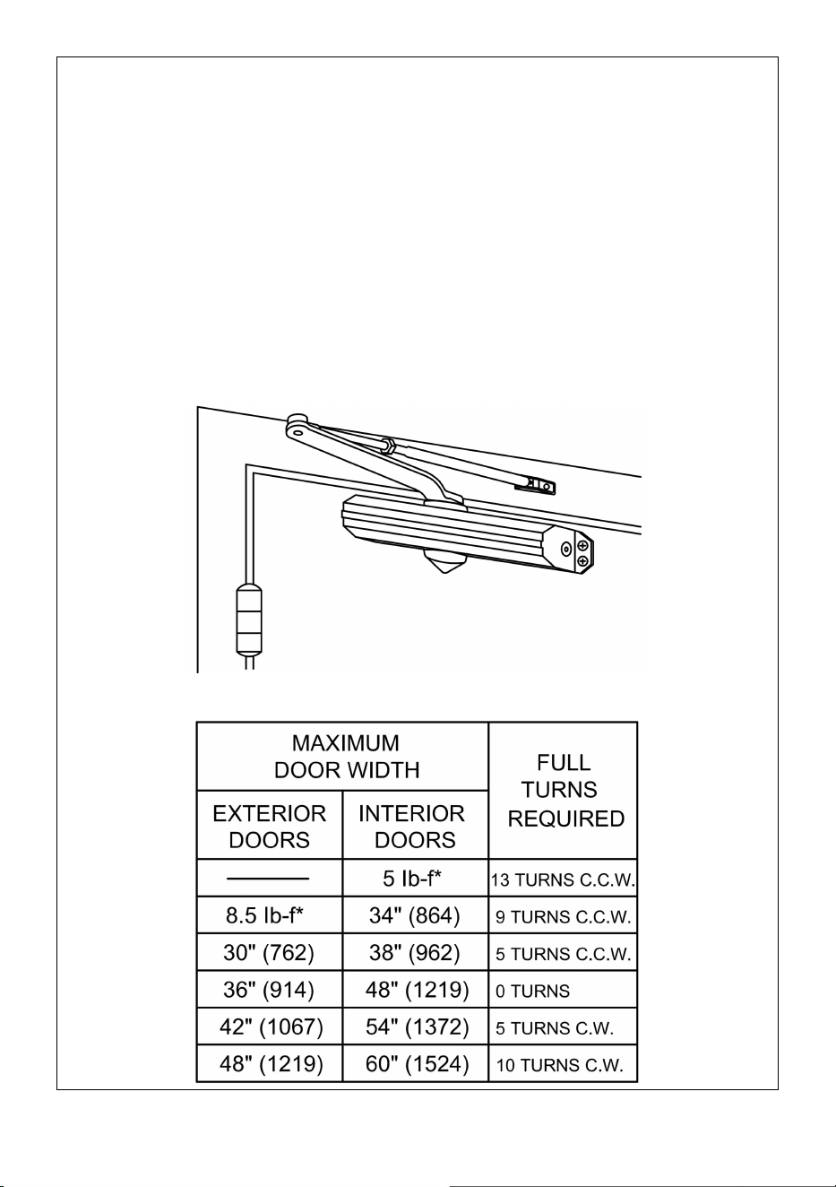
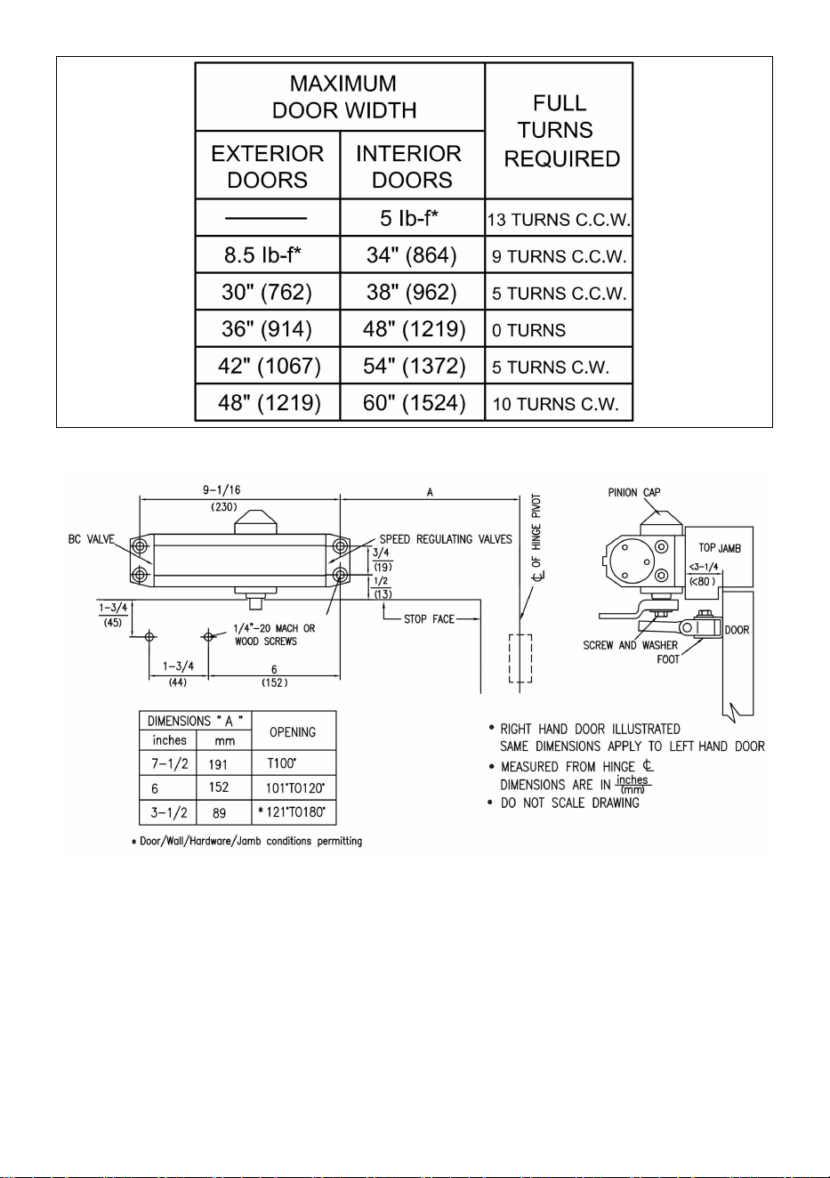
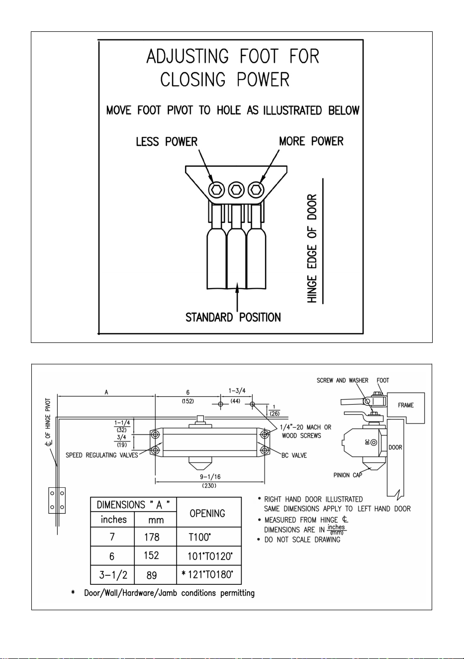
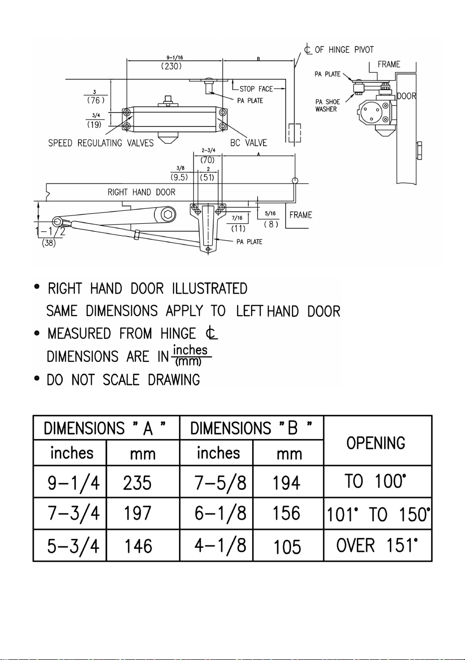
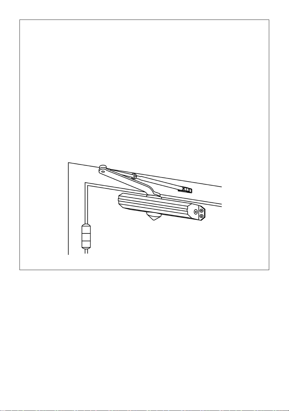
4.Final adjustment and regulating procedures.

- 7 -

- 8 -
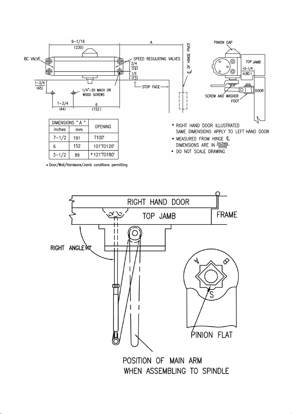
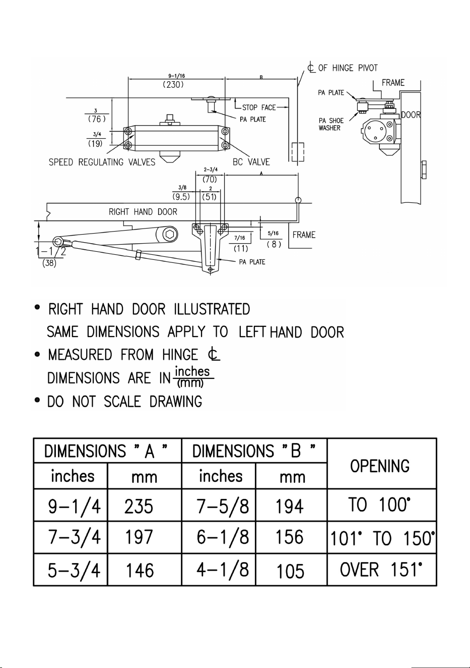
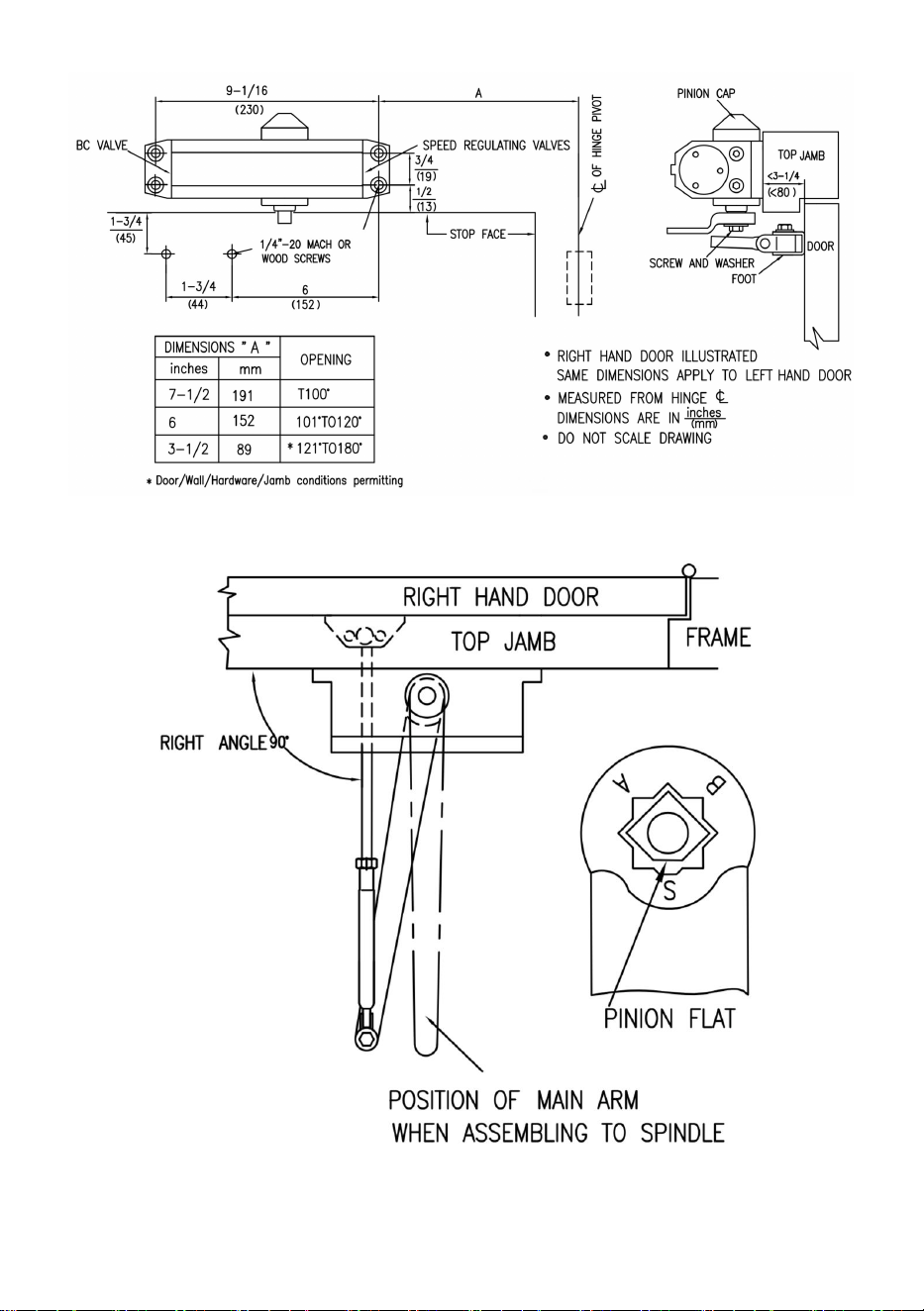
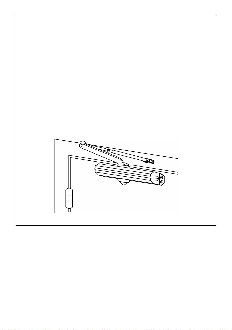
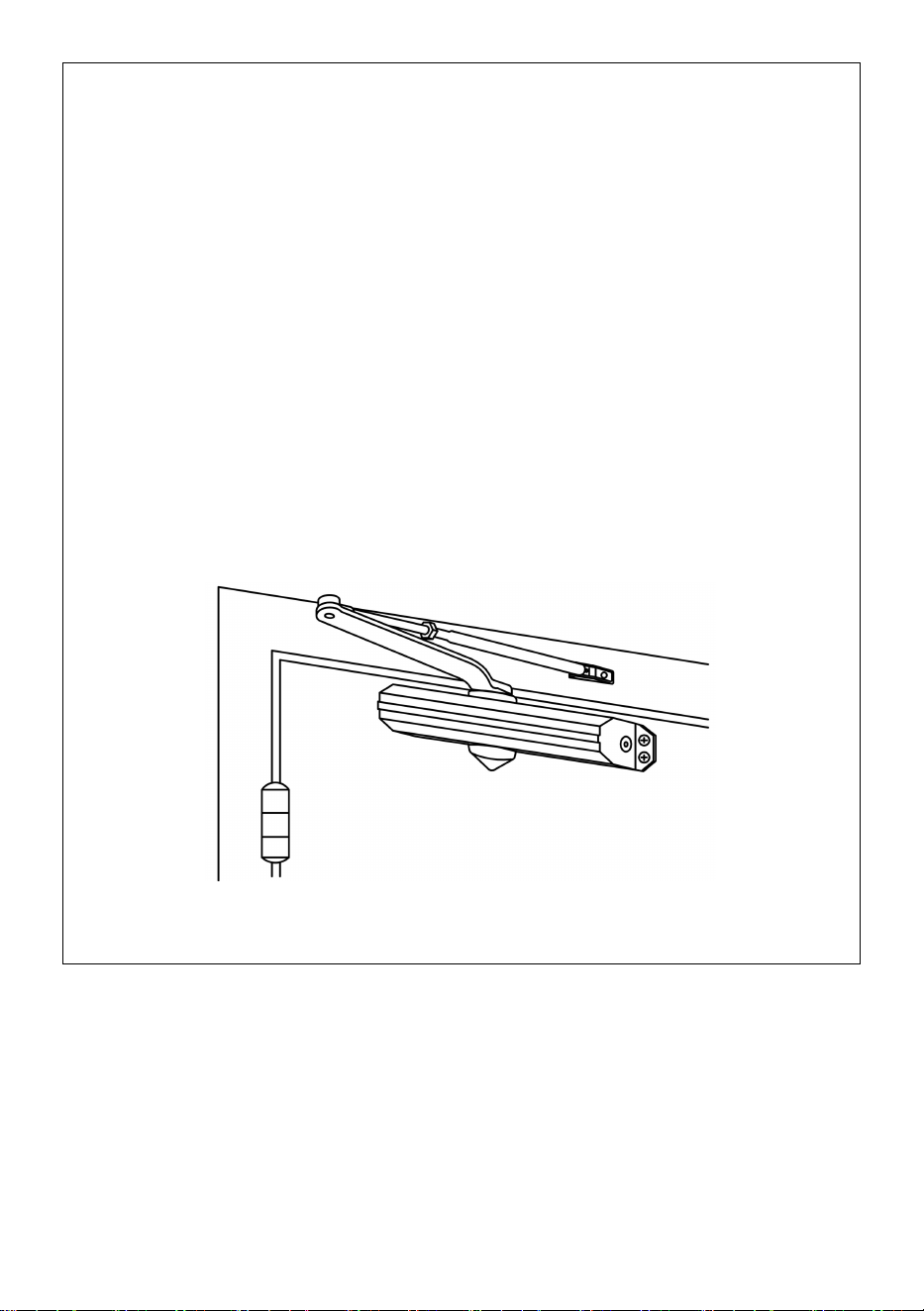
5.Regular Arm installaion.
Installation Instructions
- 9 -
1.Select degree of door.Use dimensions shown in chart and illustration
above to mark location of attaching screws on door and frame prepare
holes.
2.Assemble main arm to closer.
3.Attach closer to door with speed regulating valves toward hinge.
4.Attach the foot of the forearm to frame.
5.Adjust length of forearm to position forearm at right angle to frame
when connected to main arm at elbow use washer and screw provided to
secure pivot connection.Tighten lock nut on forearm.
6.Snap pinion cap over spindle at bottom of closer.
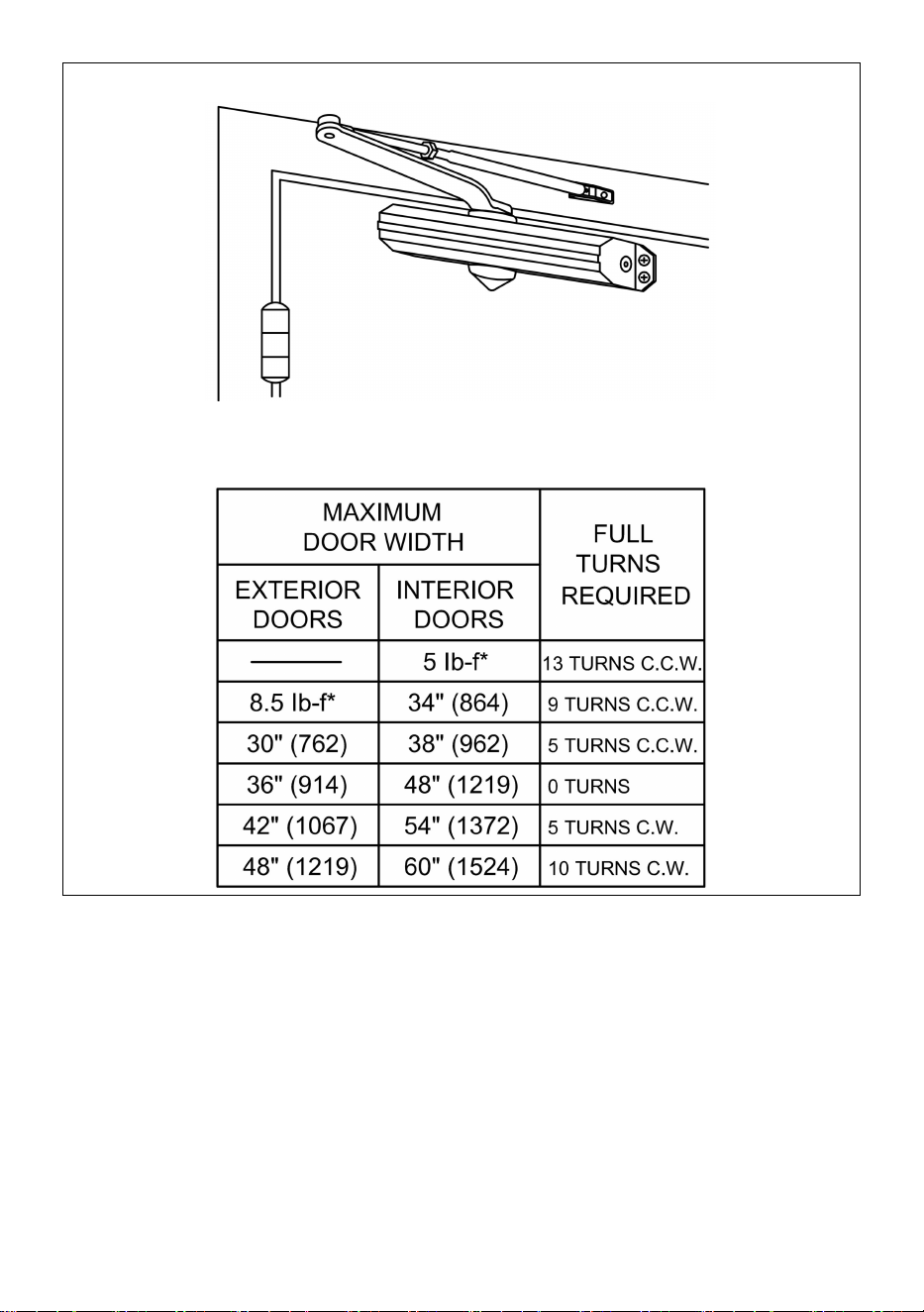
7.Adjust closer.
The chart is suitable for power adjustment door closer.
- 10 -
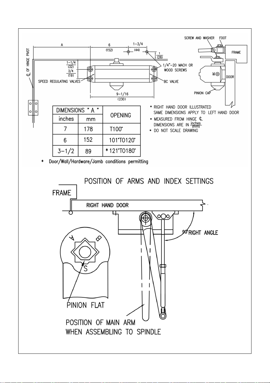
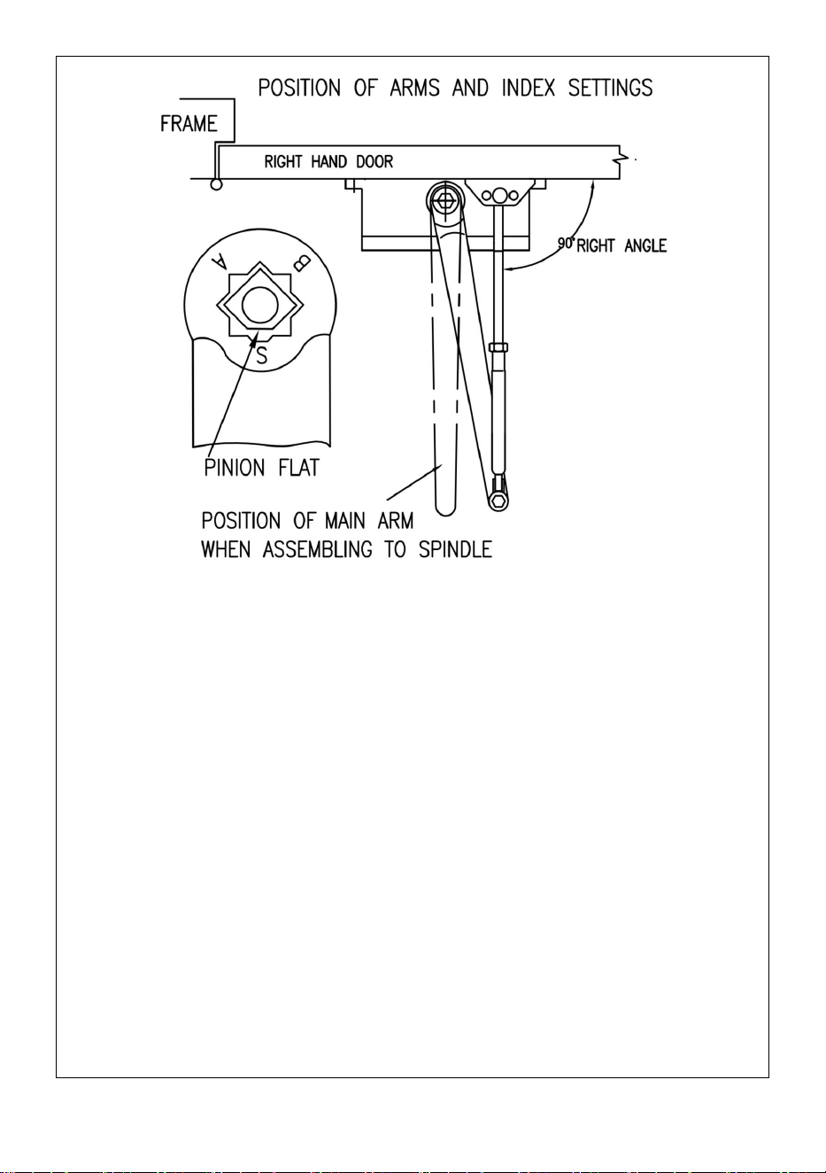
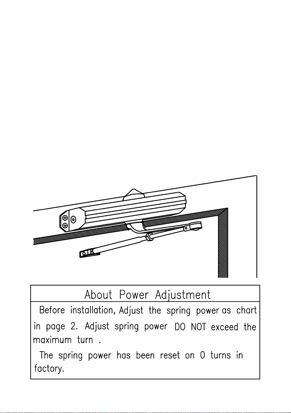
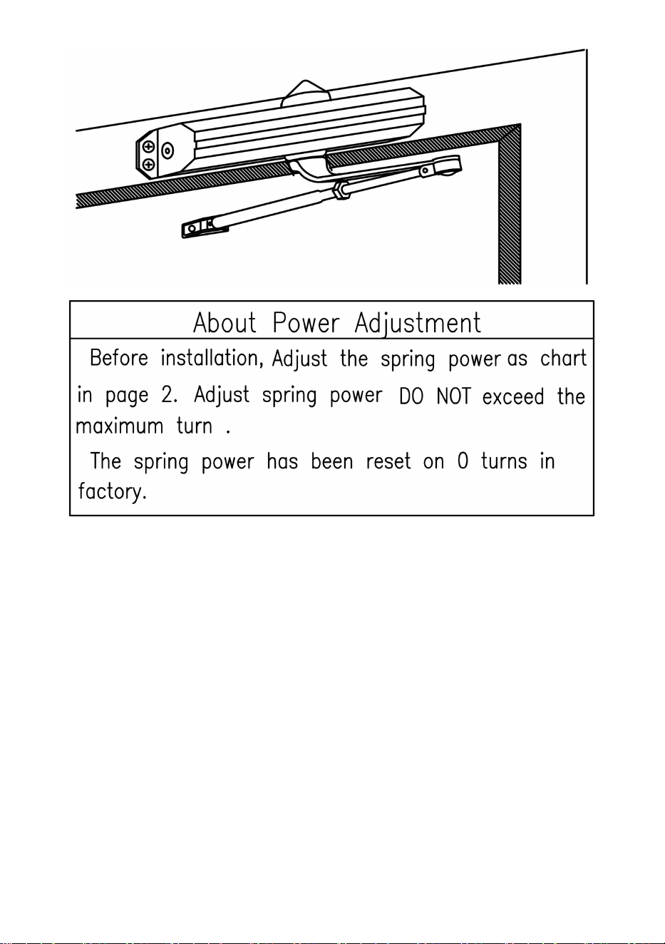
6.Top JAMB installation
Position of arms and index settings
- 11 -
Installation instructions
1.Select degree of door. Use dimensions shown in chart and illustration
above to mark location of attaching screws on door and frame prepare
holes.
2.Assemble main arm to closer.
3.Attach closer to frame with speed regulating valves toward hinge.
4.Attach the foot of the forearm to door.
5.Adjust length of forearm to position forearm at right angle to frame when
connected to main arm at elbow use washer and screw provided to secure
pivot connection. Tighten lock nut on forearm.
6.Snap pinion cap over spindle at bottom of closer.
7.Adjust closer.
- 12 -
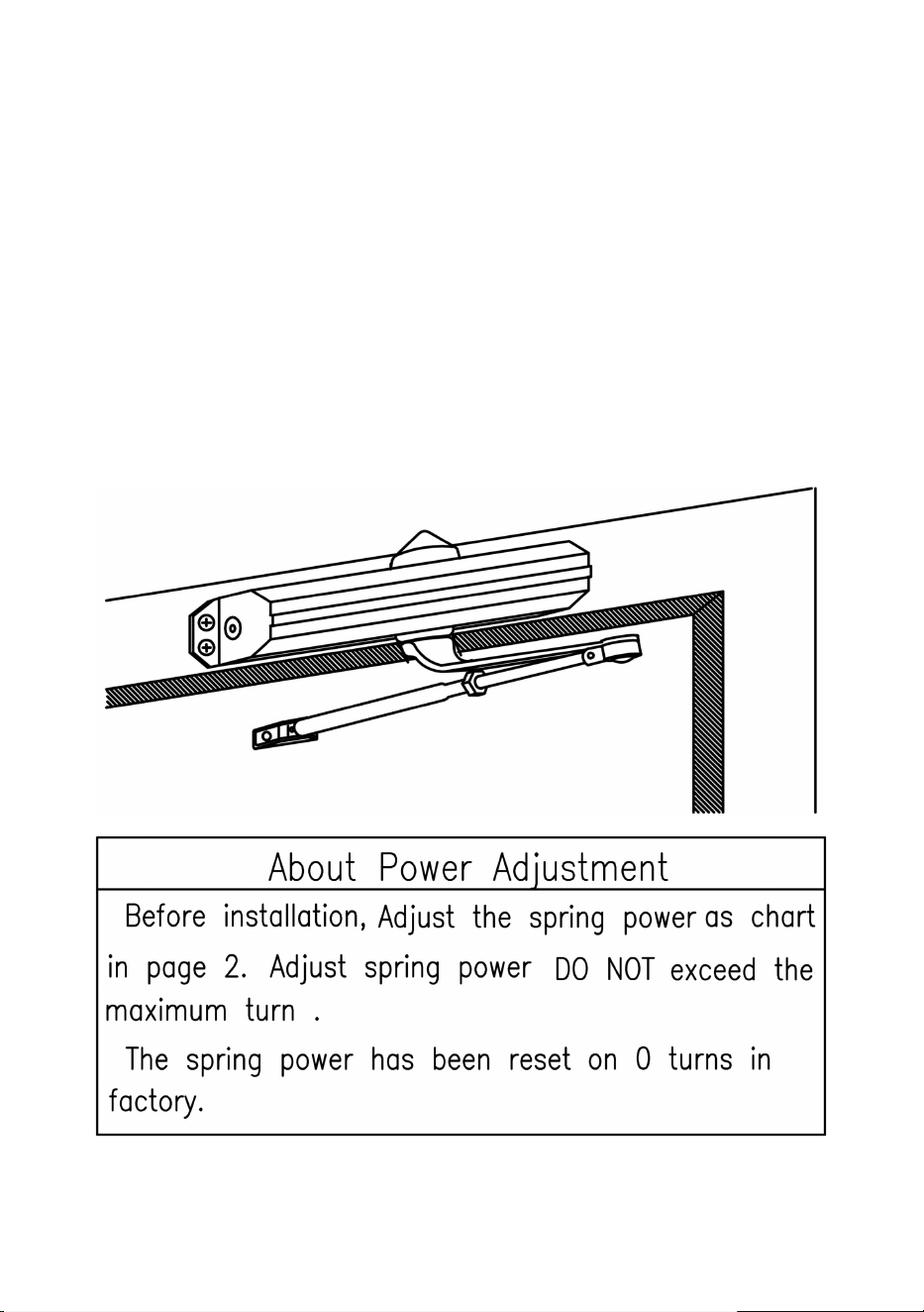
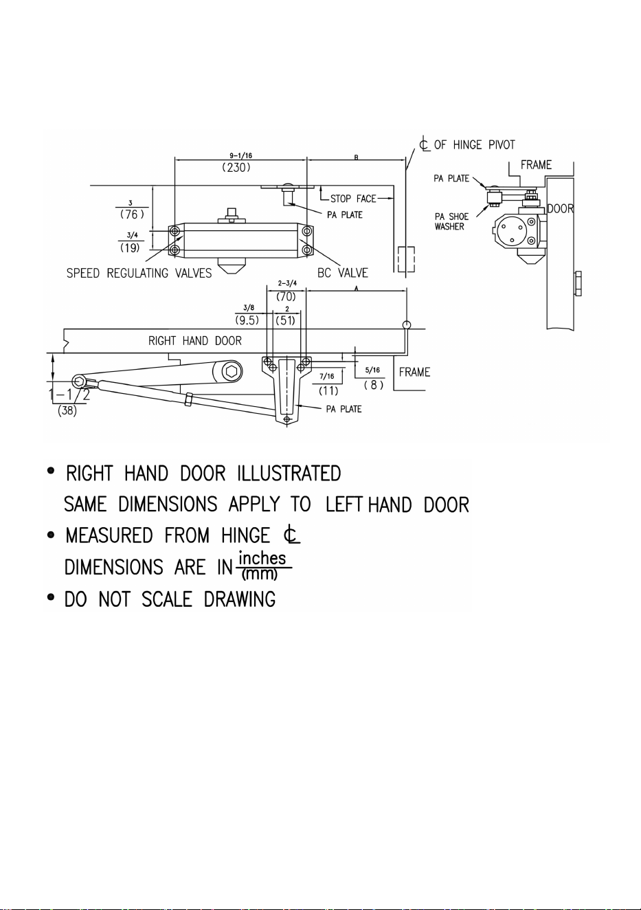
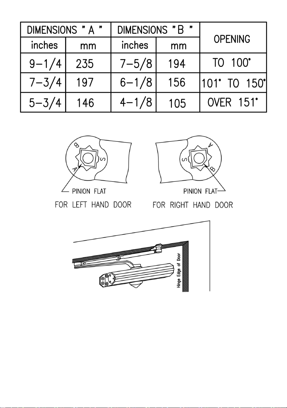
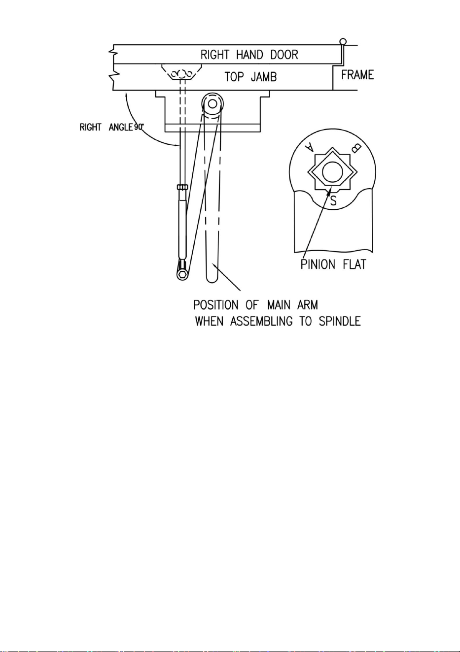
7. Parallel arm installation
- 13 -
Installation instructions
1.Select degree of door.use dimensions shown in chart and illustration
above to mark location of attaching screws on door and frame prepare
holes.
2.Attach closer to door with speed regulating valves back to hinge.
3.Attach pa plate to top frame as shown
4.Remove foot from forearm and discard.
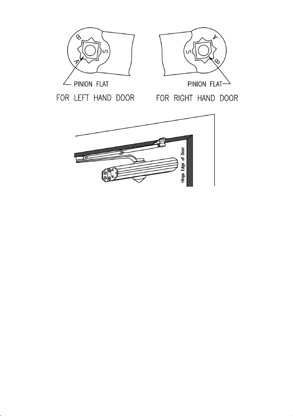
5.Install arm on pinion shaft.rotate pinion45° toward hinge edge of door to
align main arm letter “B”(right hand door)or “A”(left hand door) with pinion
flat.fasten with arm screw.
6.Fasten forearm to pa plate using screw removed from foot in step 4 and
pa shoe washer included in screw pack.
7.Adjust forearm length to set arm elbow about 1-1/2”(38mm) from door
when connected to main arm.use washer and screw provided to secure
pivot connection. Tighten lock nut.
8.Snap pinion cap over spindle at bottom
9.Adjust closer.

- 14 -
Manufacturer: Shanghaimuxinmuyeyouxiangongsi
Address: Baoshanqu Shuangchenglu 803long 11hao 1602A-1609shi
Shanghai
Imported to AUS:SIHAO PTY LTD.1 ROKEVA STREETEASTWOOD
NSW 2122 Australia
Imported to USA:Sanven Technology Ltd. Suite 250,9166 Anaheim
Place,Rancho Cucamonga,CA91730
REP
UK
Pooledas Group Ltd
Unit 5 Albert Edward House,
The Pavilions Preston, United Kingdom
pooledas123@gmail.com
01772418127
REP
EC
SHUNSHUN GmbH
Römeräcker 9 Z2021,76351
Linkenheim-Hochstetten, Germany
euvertreter@gmail.com
+49 1727041930
Made In China


- 2 -
Technique Assistance et certificat de garantie électronique
www.vevor.com/support
FERME-PORTE
MODÈLE : D4015 / D4016
We continue to be committed to provide you tools with competitive price.
"Save Half", "Half Price" or any other similar expressions used by us only represents an
estimate of savings you might benefit from buying certain tools with us compared to the major
top brands and does not necessarily mean to cover all categories of tools offered by us. You
are kindly reminded to verify carefully when you are placing an order with us if you are
actually saving half in comparison with the top major brands.

- 1 -
MODÈLE : D4015 / D4016
Have product questions? Need technical support? Please feel free to
contact us:
Technical Support and E-Warranty Certificate
www.vevor.com/support
NEED HELP? CONTACT US!
This is the original instruction, please read all manual instructions
carefully before operating. VEVOR reserves a clear interpretation of our
user manual. The appearance of the product shall be subject to the
product you received. Please forgive us that we won't inform you again if
there are any technology or software updates on our product.
DOOR CLOSER

- 2 -
AVERTISSEMENT:
1. Ne laissez pas les enfants grimper sur l'appareil.
2. Éloignez les enfants et les animaux domestiques pendant l'assemblage.
PRÉCAUTIONS DE MONTAGE
1. Veuillez assembler le produit en stricte conformité avec les instructions.
Un assemblage incorrect pourrait être dangereux.
2. Veuillez porter correctement des lunettes de sécurité et des gants de
travail pendant l'assemblage.
3. N'essayez pas d'assembler le produit lorsque vous vous sentez fatigué
ou sous l'influence de l'alcool, de drogues ou de médicaments.
4. La capacité de charge et les autres paramètres du produit sont
appliqués uniquement au produit correctement et complètement assemblé.
5. Séparez et comptez toutes les pièces et le matériel.
6. Préparez l'outil suivant : Tournevis cruciforme.
7. Si vous utilisez des outils électriques, veillez à ralentir et à vous arrêter
si nécessaire.
8. Deux personnes sont nécessaires pour le montage.
9. Suivez uniquement les utilisations prévues.
10. Utiliser uniquement sur des surfaces stables.
11 . Inspectez régulièrement les signes d’usure, de dommages ou de
pièces desserrées.
CONSERVEZ CES INSTRUCTIONS
PART LIST
Lors du déballage de ce produit, vérifiez que les pièces répertoriées
ci-dessous sont incluses et inspectez soigneusement tout dommage qui
aurait pu survenir
pendant le transit. Si seulement Une pièce est manquante ou
endommagée, n'essayez pas d'assembler ou d'utiliser le produit.

- 3 -
NON
IMAGE
NOM DE LA PIÈCE
QTÉ
UN
Corps de ferme-porte
1
B
Bras HO
1
C
Boulon de culbuteur M6×10
1
D
pour portes en bois ST6.3×30
6
E
Clé hexagonale
1
F
Vis autotaraudeuse ST6.3×38
6
g
pour portes métalliques 1/4-20×16
2
H
Portes métalliques Vis 1/4-20×25
4
je
Chapeau de pignon
1
J.
Couverture plastique
1
- 4 -
PRODUCT PAREMETERS
Modèle
D4015
D4016
Matériel
Aluminium
Aluminium
Couleur
Argenté ou Noir
Argenté ou Noir
Charge maximale
de la porte à
utiliser
265 livres
330 livres
INSTALLATION AND OPERATION INSTRUCTIONS
1. Graphique pour déterminer la main de la porte.
2.Composants.

- 5 -
3. Fonction de contrôle .

- 6 -
4. Procédures d'ajustement final et de régulation.

- 7 -
- 8 -
5. Installation du bras régulier.
instructions d'installation

- 9 -
1. Sélectionnez le degré de porte. Utilisez les dimensions indiquées
dans le tableau et l'illustration ci-dessus pour marquer l'emplacement
des vis de fixation sur la porte et les trous de préparation du cadre.
2. Assemblez le bras principal pour le fermer.
3. Fixez le ferme-porte à la porte avec les vannes de régulation de
vitesse vers la charnière.
4. Fixez le pied de l'avant-bras au cadre.
5. Ajustez la longueur de l'avant-bras pour positionner l'avant-bras à
angle droit par rapport au cadre lorsqu'il est connecté au bras principal
au niveau du coude, utilisez la rondelle et la vis fournies pour sécuriser
la connexion du pivot. Serrez le contre-écrou sur l'avant-bras.
6. Enclenchez le capuchon du pignon sur la broche au bas du
ferme-porte.
7. Ajustez plus près.
Le tableau convient au ferme-porte à réglage électrique .
- 10 -
6.Installation supérieure du JAMB
Position des bras et réglages des index

- 11 -
Instructions d'installation
1. Sélectionnez le degré de porte. Utiliser les cotes indiqué dans le tableau
et l'illustration ci-dessus pour marquer l'emplacement des vis de fixation
sur la porte et le cadre, préparez des trous .
2. Assemblez le bras principal au ferme-porte .
3. Fixez-vous plus près du cadre avec rapidité vannes de régulation vers
charnière .
4. Fixez le pied de l'avant-bras à la porte .
5. Ajustez la longueur de l'avant-bras à la position avant-bras à angle droit
par rapport au cadre lorsqu'il est connecté au bras principal au niveau du
coude utilisez la rondelle et la vis fournies pour fixer liaison pivot. Serrer le
verrou écrou sur l'avant-bras .
6. Enclenchez le capuchon du pignon sur la broche en bas de plus près .
7. Ajustez plus près .

- 12 -
8. Installation de bras parallèles

- 13 -

- 14 -
Instructions d'installation
1. Sélectionnez le degré de porte. Utilisez les dimensions indiquées dans
le tableau et l'illustration ci-dessus pour marquer l'emplacement des vis de
fixation sur la porte et les trous de préparation du cadre.
2. Fixez plus près de la porte avec les vannes de régulation de vitesse sur
la charnière.
3. Fixez la plaque pa au cadre supérieur comme indiqué
4. Retirez le pied de l'avant-bras et jetez-le.
5. Installez le bras sur l'arbre du pignon. Faites pivoter le pignon de 45°
vers le bord de la charnière de la porte pour aligner la lettre du bras
principal « B » (porte de droite) ou « A » (porte de gauche) avec le pignon
plat. Fixez avec la vis du bras.
6. Fixez l'avant-bras à la plaque pa à l'aide de la vis retirée du pied à
l'étape 4 et de la rondelle pour chaussures pa incluse dans le paquet de
vis.
7. Ajustez la longueur de l'avant-bras pour placer le coude du bras à
environ 1-1/2" (38 mm) de la porte lorsqu'il est connecté au bras principal.

- 15 -
Utilisez la rondelle et la vis fournies pour sécuriser la connexion du pivot.
Serrez le contre-écrou.
8. Enclenchez le capuchon du pignon sur la broche en bas
9. Ajustez plus près.
Fabricant: Shanghaimuxinmuyeyouxiangongsi
Adresse: Baoshanqu Shuangchenglu 803long 11ha 1602A-1609shi
Shanghai
Importé à AUS : SIHAO PTY LTD.1 ROKEVA RUEESTBOIS
Nouvelle-Galles du Sud 2122 Australie
Importé à États-Unis : Sanven Technologie Ltd. Suite 250,9166 Anaheim
Lieu, Rancho Cucamonga,CA91730
REP
UK
Pooledas Group Ltd
Unit 5 Albert Edward House,
The Pavilions Preston, United Kingdom
pooledas123@gmail.com
01772418127
REP
EC
SHUNSHUN GmbH
Römeräcker 9 Z2021,76351
Linkenheim-Hochstetten, Germany
euvertreter@gmail.com
+49 1727041930
Fabriqué en Chine

- 16 -


- 2 -
Technisch Support- und E-Garantie-Zertifikat www.vevor.com/support
TÜRSCHLIEßER
MODELL: D4015 / D4016
We continue to be committed to provide you tools with competitive price.
"Save Half", "Half Price" or any other similar expressions used by us only represents an
estimate of savings you might benefit from buying certain tools with us compared to the major
top brands and does not necessarily mean to cover all categories of tools offered by us. You
are kindly reminded to verify carefully when you are placing an order with us if you are
actually saving half in comparison with the top major brands.

- 1 -
MODELL : D4015 / D4016
Have product questions? Need technical support? Please feel free to
contact us:
Technical Support and E-Warranty Certificate
www.vevor.com/support
NEED HELP? CONTACT US!
This is the original instruction, please read all manual instructions
carefully before operating. VEVOR reserves a clear interpretation of our
user manual. The appearance of the product shall be subject to the
product you received. Please forgive us that we won't inform you again if
there are any technology or software updates on our product.
DOOR CLOSER

- 2 -
WARNUNG:
1. Erlauben Sie Kindern nicht, auf das Gerät zu klettern.
2. Halten Sie Kinder und Haustiere während der Montage fern.
VORSICHTSMASSNAHMEN BEI DER MONTAGE
1. Bitte bauen Sie das Produkt unter strikter Einhaltung der Anweisungen
zusammen. Eine falsche Montage kann gefährlich sein.
2. Bitte tragen Sie bei der Montage ordnungsgemäß eine Schutzbrille und
Arbeitshandschuhe.
3. Versuchen Sie nicht, das Produkt zusammenzubauen, wenn Sie sich
müde fühlen oder unter dem Einfluss von Alkohol, Drogen oder
Medikamenten stehen.
4. Tragfähigkeit und andere Produktparameter beziehen sich
ausschließlich auf das ordnungsgemäß und vollständig montierte Produkt.
5. Trennen und zählen Sie alle Teile und Hardware.
6. Bereiten Sie das folgende Werkzeug vor: Kreuzschlitzschraubendreher.
7. Wenn Sie Elektrowerkzeuge verwenden, achten Sie bitte darauf,
langsamer zu fahren und bei Bedarf anzuhalten.
8. Für den Aufbau sind zwei Personen erforderlich.
9. Befolgen Sie nur die vorgesehenen Verwendungszwecke.
10. Nur auf stabilen Oberflächen verwenden.
11 . Überprüfen Sie das Gerät regelmäßig auf Anzeichen von Abnutzung,
Beschädigung oder lockeren Teilen.
ANLEITUNG AUFBEWAHREN
PART LIST
Überprüfen Sie beim Auspacken dieses Produkts, ob die unten
aufgeführten Teile enthalten sind und überprüfen Sie es sorgfältig auf
etwaige Schäden
während des Transports. Wenn überhaupt Wenn ein Teil fehlt oder
- 3 -
beschädigt ist, versuchen Sie nicht, das Produkt zusammenzubauen oder
zu verwenden.
NEIN
BILD
TEILNAME
MENG
E
A
Türschließerkörper
1
B
HO-Arm
1
C
Kipphebelschraube M6×10
1
D
Holztürenschraube ST6,3×30
6
E
Sechskantschlüssel
1
F
Selbstschneidende Schraube
ST6,3×38
6
G
Metalltürschraube 1/4-20×16
2
H
Metalltüren Schrauben 1/4-20×25
4

- 4 -
ICH
Ritzelkappe
1
J
Plastikhülle
1
PRODUCT PAREMETERS
Modell
D4015
D4016
Material
Aluminium
Aluminium
Farbe
Silber oder Schwarz
Silber oder Schwarz
Zu verwendende
maximale Türlast
265 Pfund
330 Pfund
INSTALLATION AND OPERATION INSTRUCTIONS
1. Diagramm zur Bestimmung der Türhand.
- 5 -
2.Komponenten.
3. Steuerfunktion .
- 6 -
- 7 -
4. Endgültige Anpassungs- und Regulierungsverfahren.
- 8 -
5. Installation des regulären Arms.
- 9 -
Installationsanleitung
1.Wählen Sie den Grad der Tür. Markieren Sie anhand der in der Tabelle
und Abbildung oben gezeigten Maße die Position der
Befestigungsschrauben an der Tür und bereiten Sie die Löcher im
Rahmen vor.
2. Hauptarm am Schließer montieren.
3. Befestigen Sie den Schließer mit den
Geschwindigkeitsregulierventilen in Richtung Scharnier an der Tür.
4. Befestigen Sie den Fuß des Unterarms am Rahmen.
5. Passen Sie die Länge des Unterarms an, um den Unterarm im
rechten Winkel zum Rahmen zu positionieren, wenn er am Ellenbogen
mit dem Hauptarm verbunden ist. Verwenden Sie die mitgelieferte
Unterlegscheibe und Schraube, um die Drehverbindung zu sichern.
Ziehen Sie die Kontermutter am Unterarm fest.
6. Schnappen Sie die Ritzelkappe über die Spindel an der Unterseite
des Schließers.
- 10 -
7. Näher einstellen.
Die Tabelle ist für die Leistungseinstellung von Türschließern
geeignet .
6. Top JAMB-Installation
- 11 -
Position der Arme und Indexeinstellungen
Installationsanleitung
- 12 -
1. Grad der Tür auswählen. Bemaßungen verwenden siehe Tabelle und
Abbildung oben um die Position der Befestigungsschrauben zu markieren
An Tür und Rahmen Löcher vorbereiten .
2. Montieren Sie den Hauptarm am Schließer .
3. Mit Geschwindigkeit näher am Rahmen befestigen Regulierventile
Richtung Scharnier .
4. Befestigen Sie den Fuß des Unterarms an der Tür .
5. Passen Sie die Länge des Unterarms an die Position an Unterarm im
rechten Winkel zum Rahmen wenn es am Ellenbogen mit dem Hauptarm
verbunden ist Verwenden Sie zur Befestigung die mitgelieferte
Unterlegscheibe und Schraube Drehgelenkverbindung. Schloss festziehen
Nuss am Unterarm .
6. Ritzelkappe unten über die Spindel stecken von näher .
7. Näher einstellen .
- 13 -
9. Parallelarminstallation
- 14 -
Installationsanleitung
1.Wählen Sie den Grad der Tür. Markieren Sie anhand der in der Tabelle
und Abbildung oben gezeigten Maße die Position der
Befestigungsschrauben an der Tür und bereiten Sie die Löcher am
Rahmen vor.
2. Befestigen Sie den Türschließer mit Geschwindigkeitsregelventilen
wieder am Scharnier.

- 15 -
3. Befestigen Sie die PA-Platte wie abgebildet am oberen Rahmen
4. Entfernen Sie den Fuß vom Unterarm und entsorgen Sie ihn.
5. Montieren Sie den Arm auf der Ritzelwelle. Drehen Sie das Ritzel um
45° in Richtung Scharnierkante der Tür, um den Buchstaben „B“ des
Hauptarms (rechte Tür) oder „A“ (linke Tür) mit der Ritzelfläche
auszurichten. Befestigen Sie ihn mit der Armschraube.
6.Befestigen Sie den Unterarm mit der in Schritt 4 vom Fuß entfernten
Schraube und der im Schraubenpaket enthaltenen PA-Schuhscheibe an
der PA-Platte.
7. Passen Sie die Unterarmlänge an, um den Armwinkel etwa 1-1/2 Zoll
(38 mm) von der Tür entfernt einzustellen, wenn er mit dem Hauptarm
verbunden ist. Verwenden Sie die mitgelieferte Unterlegscheibe und
Schraube, um die Drehverbindung zu sichern. Kontermutter festziehen.
8. Schnappen Sie die Ritzelkappe unten über die Spindel
9.Näher einstellen.
Hersteller: Shanghaimuxinmuyeyouxiangongsi
Adresse: Baoshanqu Shuangchenglu 803lang 11hao 1602A-1609shi
Shanghai
Importiert Zu AUS: SIHAO PTY LTD.1 ROKEVA STREETEASTWOOD
NSW 2122 Australien
Importiert Zu USA: Sanven Technologie GmbH. Suite 250.9166 Anaheim
Ort, Rancho Cucamonga, CA91730
REP
UK
Pooledas Group Ltd
Unit 5 Albert Edward House,
The Pavilions Preston, United Kingdom
pooledas123@gmail.com
01772418127
REP
EC
SHUNSHUN GmbH
Römeräcker 9 Z2021,76351
Linkenheim-Hochstetten, Germany
euvertreter@gmail.com
+49 1727041930

- 16 -
In China hergestellt


- 2 -
Tecnico Supporto e certificato di garanzia elettronica www.vevor.com/support
CHIUDIPORTA
MODELLO: D4015 / D4016
We continue to be committed to provide you tools with competitive price.
"Save Half", "Half Price" or any other similar expressions used by us only represents an
estimate of savings you might benefit from buying certain tools with us compared to the major
top brands and does not necessarily mean to cover all categories of tools offered by us. You
are kindly reminded to verify carefully when you are placing an order with us if you are
actually saving half in comparison with the top major brands.

- 1 -
MODELLO : D4015 / D4016
Have product questions? Need technical support? Please feel free to
contact us:
Technical Support and E-Warranty Certificate
www.vevor.com/support
NEED HELP? CONTACT US!
This is the original instruction, please read all manual instructions
carefully before operating. VEVOR reserves a clear interpretation of our
user manual. The appearance of the product shall be subject to the
product you received. Please forgive us that we won't inform you again if
there are any technology or software updates on our product.
DOOR CLOSER

- 2 -
AVVERTIMENTO:
1. Non permettere ai bambini di salire sull'unità.
2. Tenere lontani i bambini e gli animali domestici durante il montaggio.
PRECAUZIONI DI MONTAGGIO
1. Si prega di assemblare il prodotto attenendosi rigorosamente alle
istruzioni. Un montaggio errato potrebbe essere pericoloso.
2. Indossare correttamente occhiali protettivi e guanti da lavoro durante il
montaggio.
3. Non tentare di montare il prodotto quando ci si sente stanchi o sotto
l'effetto di alcol, droghe o farmaci.
4. La capacità di carico e altri parametri del prodotto vengono applicati solo
al prodotto correttamente e completamente assemblato.
5. Separare e contare tutte le parti e l'hardware.
6. Preparare il seguente strumento: cacciavite a croce.
7. Se si utilizzano utensili elettrici, fare attenzione a rallentare e fermarsi
quando necessario.
8. Per il montaggio sono necessarie due persone.
9. Seguire solo gli usi previsti.
10. Utilizzare solo su superfici stabili.
11 . Ispezionare regolarmente eventuali segni di usura, danni o parti
allentate.
CONSERVARE QUESTE ISTRUZIONI S
PART LIST
Quando si disimballa il prodotto, verificare che le parti elencate di seguito
siano incluse e ispezionare attentamente eventuali danni che potrebbero
essersi verificati
durante il transito. Se presente parte mancante o danneggiata, non tentare
di montare o utilizzare il prodotto.
- 3 -
NO
IMMAGINE
NOME DELLA PARTE
QUAN
TITÀ
UN
Corpo chiudiporta
1
B
Braccio HO
1
C
Bullone del bilanciere M6×10
1
D
per Porte in Legno ST6.3×30
6
E
Chiave esagonale
1
F
Vite Autofilettante ST6.3×38
6
G
per porte in metallo 1/4-20×16
2
H
Porte in metallo Vite 1/4-20×25
4
IO
Tappo pignone
1
- 4 -
J
Cover di plastica
1
PRODUCT PAREMETERS
Modello
D4015
D4016
Materiale
Alluminio
Alluminio
Colore
Argentato o Nero
Argentato o Nero
Carico massimo
della porta da
utilizzare
265 libbre
330 libbre
INSTALLATION AND OPERATION INSTRUCTIONS
1.Grafico per determinare la mano della porta.
- 5 -
2.Componenti.
3. Funzione di controllo .

- 6 -
4. Procedure finali di aggiustamento e regolazione.

- 7 -

- 8 -
5. Installazione regolare del braccio.
Istruzioni per l'installazione
- 9 -
1. Selezionare il grado della porta. Utilizzare le dimensioni mostrate nella
tabella e nell'illustrazione sopra per contrassegnare la posizione delle viti
di fissaggio sulla porta e preparare i fori sul telaio.
2.Assemblare il braccio principale per avvicinarlo.
3. Fissare più vicino alla porta con le valvole di regolazione della velocità
verso la cerniera.
4. Attaccare il piede dell'avambraccio al telaio.
5. Regolare la lunghezza dell'avambraccio per posizionarlo ad angolo
retto rispetto al telaio quando è collegato al braccio principale al gomito,
utilizzare la rondella e la vite fornite per fissare il collegamento del perno.
Stringere il dado di bloccaggio sull'avambraccio.
6. Far scattare il cappuccio del pignone sul perno nella parte inferiore del
chiudiporta.
7. Regolare più da vicino.
Il grafico è adatto per il chiudiporta con regolazione della potenza .

- 10 -
6.Installazione superiore dello JAMB
Posizione delle braccia e impostazioni degli indici

- 11 -
Istruzioni per l'installazione
1. Selezionare il grado della porta. Usa le dimensioni mostrato nel grafico e
nell'illustrazione sopra per contrassegnare la posizione delle viti di
fissaggio su anta e telaio predisporre i fori .
2. Assemblare il braccio principale al più vicino .
3. Attaccalo più vicino al telaio con velocità valvole di regolazione verso la
cerniera .
4. Attaccare il piede dell'avambraccio alla porta .
5. Regolare la lunghezza dell'avambraccio in posizione avambraccio ad
angolo retto rispetto al telaio quando collegato al braccio principale al
gomito utilizzare la rondella e la vite fornite per fissarlo collegamento a
perno. Stringere la serratura dado sull'avambraccio .
6. Far scattare il cappuccio del pignone sul perno in basso di più vicino .
7. Regolare più da vicino .

- 12 -
10.Installazione a braccio parallelo
- 13 -

- 14 -
Istruzioni per l'installazione
1. Selezionare il grado della porta. Utilizzare le dimensioni mostrate nella
tabella e nell'illustrazione sopra per contrassegnare la posizione delle viti
di fissaggio sulla porta e preparare i fori sul telaio.
2.Fissare il più vicino alla porta con le valvole di regolazione della velocità
sul cardine.
3.Attaccare la piastra PA al telaio superiore come mostrato
4.Rimuovere il piede dall'avambraccio e scartarlo.
5.Installare il braccio sull'albero del pignone. Ruotare il pignone di 45°
verso il bordo della cerniera della porta per allineare la lettera "B" del
braccio principale (porta a destra) o "A" (porta a sinistra) con il pignone
piatto. Fissare con la vite del braccio.
6.Fissare l'avambraccio alla piastra PA utilizzando la vite rimossa dal piede
al punto 4 e la rondella per scarpe inclusa nella confezione delle viti.
7.Regolare la lunghezza dell'avambraccio per impostare il gomito del
braccio a circa 1-1/2” (38 mm) dalla porta quando è collegato al braccio
principale. Utilizzare la rondella e la vite fornite per fissare il collegamento

- 15 -
del perno. Stringere il dado di bloccaggio.
8.Scattare il cappuccio del pignone sul perno in basso
9.Regolare più vicino.
Produttore: Shanghaimuxinmuyeyouxiangongsi
Indirizzo: Baoshanqu Shuangchenglu 803 lungo 11hao 1602A-1609shi
Shangai
Importato A Australia: SIHAO PTY LTD.1 ROKEVA
STREETEASTWOOD
Nuovo Galles del Sud 2122 Australia
Importato A Stati Uniti: Sanven Tecnologia Ltd. Suite 250,9166 Anaheim
Posto, Rancho Cucamonga,CA91730
REP
UK
Pooledas Group Ltd
Unit 5 Albert Edward House,
The Pavilions Preston, United Kingdom
pooledas123@gmail.com
01772418127
REP
EC
SHUNSHUN GmbH
Römeräcker 9 Z2021,76351
Linkenheim-Hochstetten, Germany
euvertreter@gmail.com
+49 1727041930
Made in China

- 16 -


- 2 -
Técnico Soporte y certificado de garantía electrónica www.vevor.com/support
CIERRA PUERTAS
MODELO: D4015 / D4016
We continue to be committed to provide you tools with competitive price.
"Save Half", "Half Price" or any other similar expressions used by us only represents an
estimate of savings you might benefit from buying certain tools with us compared to the major
top brands and does not necessarily mean to cover all categories of tools offered by us. You
are kindly reminded to verify carefully when you are placing an order with us if you are
actually saving half in comparison with the top major brands.

- 1 -
MODELO : D4015 / D4016
Have product questions? Need technical support? Please feel free to
contact us:
Technical Support and E-Warranty Certificate
www.vevor.com/support
NEED HELP? CONTACT US!
This is the original instruction, please read all manual instructions
carefully before operating. VEVOR reserves a clear interpretation of our
user manual. The appearance of the product shall be subject to the
product you received. Please forgive us that we won't inform you again if
there are any technology or software updates on our product.
DOOR CLOSER

- 2 -
ADVERTENCIA:
1. No permita que los niños se suban a la unidad.
2. Mantenga alejados a los niños y las mascotas durante el montaje.
PRECAUCIONES DE MONTAJE
1. Ensamble el producto estrictamente de acuerdo con las instrucciones.
El montaje incorrecto podría ser peligroso.
2. Utilice gafas de seguridad y guantes de trabajo correctamente durante
el montaje.
3. No intente montar el producto cuando se sienta cansado o bajo la
influencia del alcohol, drogas o medicamentos.
4. La capacidad de carga y otros parámetros del producto se aplican
únicamente al producto ensamblado de manera adecuada y completa.
5. Separe y cuente todas las piezas y herrajes.
6. Prepare la siguiente herramienta: Destornillador Philips.
7. Si utiliza herramientas eléctricas, tenga cuidado de reducir la velocidad
y detenerse cuando sea necesario.
8. Para el montaje se necesitan dos personas.
9. Siga únicamente los usos previstos.
10. Úselo únicamente en superficies estables.
11 . Inspeccione periódicamente para detectar signos de desgaste, daños
o piezas sueltas.
GUARDA ESTAS INSTRUCCIONES
PART LIST
Al desembalar este producto, verifique que las piezas que se enumeran a
continuación estén incluidas e inspeccione cuidadosamente por cualquier
daño que pueda haber ocurrido
durante el tránsito. Si alguna Falta alguna pieza o está dañada, no intente
ensamblar ni utilizar el producto.

- 3 -
NO
IMAGEN
NOMBRE DE LA PARTE
CANTI
DAD
A
Cuerpo del cierrapuertas
1
B
Brazo HO
1
C
Perno del balancín M6×10
1
D
Tornillo Puertas Madera ST6.3×30
6
mi
Llave hexagonal
1
F
Tornillo autorroscante ST6.3×38
6
GRA
MO
Puertas Metálicas 1/4-20×16
2
h
Puertas Metálicas Tornillo 1/4-20×25
4
I
Tapa de piñón
1
- 4 -
j
Cubierta plástica
1
PRODUCT PAREMETERS
Modelo
D4015
D4016
Material
Aluminio
Aluminio
Color
Plateado o negro
Plateado o negro
Carga máxima de
puerta a utilizar
265 libras
330 libras
INSTALLATION AND OPERATION INSTRUCTIONS
1.Gráfico para determinar la mano de la puerta.
- 5 -
2.Componentes.
3. Función de control .

- 6 -
4. Procedimientos finales de ajuste y regulación.

- 7 -

- 8 -
5. Instalación normal del brazo.
Instrucciones de instalación

- 9 -
1.Seleccione el grado de la puerta. Utilice las dimensiones que se
muestran en el cuadro y la ilustración de arriba para marcar la ubicación
de los tornillos de fijación en la puerta y los orificios de preparación del
marco.
2.Ensamble el brazo principal al cierrapuertas.
3. Conecte el cierrapuertas a la puerta con las válvulas reguladoras de
velocidad hacia la bisagra.
4. Fije el pie del antebrazo al marco.
5. Ajuste la longitud del antebrazo para colocarlo en ángulo recto con
respecto al marco cuando esté conectado al brazo principal en el codo;
use la arandela y el tornillo proporcionados para asegurar la conexión
de pivote. Apriete la contratuerca en el antebrazo.
6. Coloque la tapa del piñón sobre el eje en la parte inferior del
cierrapuertas.
7. Ajuste más cerca.
La tabla es adecuada para el cierre eléctrico de puertas .

- 10 -
6.Instalación superior de JAMB
Posición de los brazos y configuración del índice.

- 11 -
Instrucciones de instalación
1. Seleccione el grado de puerta. Usar dimensiones se muestra en el
cuadro y la ilustración de arriba para marcar la ubicación de los tornillos de
fijación En la puerta y el marco prepare agujeros .
2. Ensamble el brazo principal al cierrapuertas .
3. Adjunte más cerca del marco con velocidad válvulas reguladoras hacia
la bisagra .
4. Coloque el pie del antebrazo en la puerta .
5. Ajuste la longitud del antebrazo a la posición. antebrazo en ángulo recto
con el marco cuando se conecta al brazo principal en el codo use la
arandela y el tornillo proporcionados para asegurar conexión de pivote.
Apretar la cerradura tuerca en el antebrazo .
6. Coloque la tapa del piñón sobre el eje en la parte inferior. de más cerca .
7. Ajuste más cerca .

- 12 -
11.Instalación de brazos paralelos

- 13 -

- 14 -
Instrucciones de instalación
1.Seleccione el grado de la puerta. Utilice las dimensiones que se
muestran en la tabla y la ilustración de arriba para marcar la ubicación de
los tornillos de fijación en la puerta y prepare los orificios del marco.
2.Coloque el cierrapuertas a la puerta con las válvulas reguladoras de
velocidad nuevamente a la bisagra.
3.Fije la placa pa al marco superior como se muestra
4.Retire el pie del antebrazo y deséchelo.
5.Instale el brazo en el eje del piñón. Gire el piñón 45° hacia el borde de la
bisagra de la puerta para alinear la letra “B” (puerta derecha) o “A” (puerta
izquierda) del brazo principal con el piñón plano. Sujete con el tornillo del
brazo.
6.Sujete el antebrazo a la placa pa usando el tornillo que quitó del pie en el
paso 4 y la arandela de zapato pa incluida en el paquete de tornillos.
7.Ajuste la longitud del antebrazo para colocar el codo del brazo
aproximadamente a 1-1/2”(38 mm) de la puerta cuando esté conectado al
brazo principal. Utilice la arandela y el tornillo proporcionados para

- 15 -
asegurar la conexión de pivote. Apriete la contratuerca.
8.Coloque la tapa del piñón sobre el eje en la parte inferior.
9.Ajuste más cerca.
Fabricante: Shanghaimuxinmuyeyouxiangongsi
DIRECCIÓN: Baoshanqu Shuangchenglu 803largo 11hao 1602A-1609shi
Llevar a la fuerza
Importado a AUS: SIHAO PTY LTD.1 ROKEVA CALLE ASTWOOD
Nueva Gales del Sur 2122 Australia
Importado a Estados Unidos: Sanven Tecnología Limitado. Suite
250,9166 anaheim
Lugar, Rancho Cucamonga,CA91730
REP
UK
Pooledas Group Ltd
Unit 5 Albert Edward House,
The Pavilions Preston, United Kingdom
pooledas123@gmail.com
01772418127
REP
EC
SHUNSHUN GmbH
Römeräcker 9 Z2021,76351
Linkenheim-Hochstetten, Germany
euvertreter@gmail.com
+49 1727041930
Hecho en china

- 16 -


- 2 -
Techniczny Certyfikat wsparcia i e-gwarancji www.vevor.com/support
DRZWI BLIŻEJ
MODEL: D4015 / D4016
We continue to be committed to provide you tools with competitive price.
"Save Half", "Half Price" or any other similar expressions used by us only represents an
estimate of savings you might benefit from buying certain tools with us compared to the major
top brands and does not necessarily mean to cover all categories of tools offered by us. You
are kindly reminded to verify carefully when you are placing an order with us if you are
actually saving half in comparison with the top major brands.

- 1 -
MODEL : D4015 / D4016
Have product questions? Need technical support? Please feel free to
contact us:
Technical Support and E-Warranty Certificate
www.vevor.com/support
NEED HELP? CONTACT US!
This is the original instruction, please read all manual instructions
carefully before operating. VEVOR reserves a clear interpretation of our
user manual. The appearance of the product shall be subject to the
product you received. Please forgive us that we won't inform you again if
there are any technology or software updates on our product.
DOOR CLOSER

- 2 -
OSTRZEŻENIE:
1. Nie pozwalaj dzieciom wspinać się na urządzenie.
2. Podczas montażu trzymaj dzieci i zwierzęta z daleka.
ŚRODKI OSTROŻNOŚCI PRZY MONTAŻU
1. Prosimy o złożenie produktu ściśle według instrukcji. Nieprawidłowy
montaż może być niebezpieczny.
2. Podczas montażu należy nosić okulary ochronne i rękawice robocze.
3. Nie przystępuj do składania produktu będąc zmęczonym, pod wpływem
alkoholu, narkotyków lub leków.
4. Nośność i inne parametry produktu odnoszą się wyłącznie do produktu
prawidłowo i całkowicie zmontowanego.
5. Oddziel i policz wszystkie części i osprzęt.
6. Przygotuj następujące narzędzie: Śrubokręt Philips.
7. Jeśli korzystasz z elektronarzędzi, pamiętaj, aby zwolnić i zatrzymać się,
jeśli zajdzie taka potrzeba.
8. Do montażu potrzebne są dwie osoby.
9. Postępuj zgodnie z przeznaczeniem.
10. Używaj wyłącznie na stabilnych powierzchniach.
11 . Regularnie sprawdzaj, czy nie występują oznaki zużycia, uszkodzenia
lub luźne części.
ZACHOWAJ TĘ INSTRUKCJĘ S
PART LIST
Rozpakowując ten produkt, sprawdź, czy w zestawie znajdują się
wymienione poniżej części i dokładnie sprawdź, czy nie wystąpiły żadne
uszkodzenia
podczas transportu. Jeśli w ogóle brakuje jakiejś części lub jest ona
uszkodzona, nie próbuj montować ani używać produktu.
- 3 -
NIE
ZDJĘCIE
CZĘŚCIOWE IMIĘ
ILOŚĆ
A
Korpus samozamykacza
1
B
Ramię HO
1
C
Śruba wahacza M6×10
1
D
Drzwi drewniane Wkręt ST6,3×30
6
mi
Klucz sześciokątny
1
F
Wkręt samogwintujący ST6,3×38
6
G
Drzwi metalowe Śruba 1/4-20×16
2
H
Drzwi metalowe Śruba 1/4-20×25
4
I
Nakładka na zębnik
1
J
Plastikowa obudowa
1
- 4 -
PRODUCT PAREMETERS
Model
D4015
D4016
Materiał
Aluminium
Aluminium
Kolor
Srebrzysty lub czarny
Srebrzysty lub czarny
obciążenie drzwi
do użycia
265 funtów
330 funtów
INSTALLATION AND OPERATION INSTRUCTIONS
1.Wykres określający rękę drzwi.
2. Komponenty.

- 5 -
3. Funkcja kontrolna .
- 6 -
4. Procedury końcowej regulacji i regulacji.
- 7 -

- 8 -
5. Regularna instalacja ramienia.
Instrukcje Instalacji
- 9 -
1.Wybierz stopień drzwi. Skorzystaj z wymiarów pokazanych na
powyższej tabeli i ilustracji, aby zaznaczyć położenie śrub mocujących
na drzwiach i ościeżnicy, przygotuj otwory.
2. Zamontuj ramię główne w celu zamknięcia.
3. Zamocuj bliżej drzwi, kierując zawory regulujące prędkość w stronę
zawiasów.
4. Przymocuj stopę przedramienia do ramy.
5. Wyreguluj długość przedramienia, aby ustawić je pod kątem prostym
do ramy po podłączeniu do głównego ramienia na łokciu, użyj podkładki i
śruby dostarczonej w celu zabezpieczenia połączenia obrotowego.
Dokręć nakrętkę zabezpieczającą na przedramieniu.
6. Załóż pokrywę zębnika na wrzeciono u dołu samozamykacza.
7. Ustaw bliżej.
Wykres nadaje się do regulacji mocy samozamykacza .

- 10 -
6. Instalacja ościeża górnego
Pozycja ramion i ustawienia indeksu

- 11 -
Instrukcje Instalacji
1. Wybierz stopień drzwi. Użyj wymiarów pokazano na powyższym
wykresie i ilustracji aby oznaczyć położenie śrub mocujących na drzwiach i
ościeżnicy przygotować otwory .
2. Zamontuj ramię główne do zamykacza .
3. Szybko przymocuj bliżej ramy zawory regulacyjne w kierunku zawiasu .
4. Przymocuj stopę przedramienia do drzwi .
5. Dostosuj długość przedramienia do odpowiedniej pozycji przedramię
ustawione pod kątem prostym do ramy po podłączeniu do głównego
ramienia w łokciu użyj dostarczonej podkładki i śruby, aby zabezpieczyć
połączenie obrotowe. Dokręć zamek orzech na przedramieniu .
6. Załóż pokrywę zębnika na wrzeciono u dołu z bliższych .
7. Dostosuj bliżej .

- 12 -
12.Montaż ramienia równoległego

- 13 -

- 14 -
Instrukcje Instalacji
1.Wybierz stopień drzwi. Użyj wymiarów pokazanych na powyższej tabeli i
ilustracji, aby zaznaczyć położenie śrub mocujących na drzwiach i
ościeżnicy, przygotuj otwory.
2. Przymocuj bliżej drzwi, a zawory regulujące prędkość z powrotem do
zawiasu.
3. Przymocuj płytkę pa do górnej ramy, jak pokazano
4. Zdejmij stopę z przedramienia i wyrzuć.
5. Zamontuj ramię na wałku zębnika. Obróć zębnik o 45° w kierunku
krawędzi zawiasu drzwi, aby wyrównać literę „B” głównego ramienia (drzwi
prawe) lub „A” (drzwi lewe) z zębnikiem na płasko. Przymocuj śrubą
ramienia.
6. Przymocuj przedramię do płytki pa za pomocą śruby wykręconej ze
stopy w kroku 4 i podkładki buta pa dołączonej do zestawu śrub.
7. Wyreguluj długość przedramienia, aby ustawić łokieć ramienia na około
1-1/2” (38 mm) od drzwi, gdy jest ono podłączone do głównego ramienia.
Użyj dostarczonej podkładki i śruby, aby zabezpieczyć połączenie

- 15 -
obrotowe. Dokręć nakrętkę zabezpieczającą.
8.Załóż nasadkę koła zębatego na wrzeciono u dołu
9. Dopasuj bliżej.
Producent: Shanghaimuxinmuyeyouxiangongsi
Adres: Baoshanqu Shuangchenglu 803długa 11hao 1602A-1609shi
Szanghaj
Importowany Do AUS: SIHAO PTY LTD.1 ROKEVA
STREETEASTWOOD
Nowa Południowa Walia 2122 Australia
Importowany Do USA: Sanven Technologia Sp. z o.o. Zestaw 250,9166
Anaheim
Miejsce, Rancho Cucamonga, CA91730
REP
UK
Pooledas Group Ltd
Unit 5 Albert Edward House,
The Pavilions Preston, United Kingdom
pooledas123@gmail.com
01772418127
REP
EC
SHUNSHUN GmbH
Römeräcker 9 Z2021,76351
Linkenheim-Hochstetten, Germany
euvertreter@gmail.com
+49 1727041930
Wyprodukowano w Chinach

- 16 -


- 2 -
Technisch Ondersteuning en e-garantiecertificaat www.vevor.com/support
DEUR DICHTERBIJ
MODEL: D4015 / D4016
We continue to be committed to provide you tools with competitive price.
"Save Half", "Half Price" or any other similar expressions used by us only represents an
estimate of savings you might benefit from buying certain tools with us compared to the major
top brands and does not necessarily mean to cover all categories of tools offered by us. You
are kindly reminded to verify carefully when you are placing an order with us if you are
actually saving half in comparison with the top major brands.
- 1 -
MODEL : D4015 / D4016
Have product questions? Need technical support? Please feel free to
contact us:
Technical Support and E-Warranty Certificate
www.vevor.com/support
NEED HELP? CONTACT US!
This is the original instruction, please read all manual instructions
carefully before operating. VEVOR reserves a clear interpretation of our
user manual. The appearance of the product shall be subject to the
product you received. Please forgive us that we won't inform you again if
there are any technology or software updates on our product.
DOOR CLOSER

- 2 -
WAARSCHUWING:
1. Laat kinderen niet op het apparaat klimmen.
2. Houd kinderen en huisdieren tijdens de montage uit de buurt.
MONTAGEVOORZORGSMAATREGELEN
1. Monteer het product strikt volgens de instructies. Een onjuiste montage
kan gevaarlijk zijn.
2. Draag tijdens de montage een veiligheidsbril en werkhandschoenen.
3. Probeer het product niet in elkaar te zetten als u zich moe voelt of onder
invloed bent van alcohol, drugs of medicijnen.
4. Draagvermogen en andere productparameters gelden alleen voor het
correct en volledig gemonteerde product.
5. Scheid en tel alle onderdelen en hardware.
6. Houd het volgende gereedschap gereed: kruiskopschroevendraaier.
7. Als u elektrisch gereedschap gebruikt, zorg er dan voor dat u langzamer
gaat rijden en stopt wanneer dat nodig is.
8. Voor de montage zijn twee personen nodig.
9. Volg uitsluitend het beoogde gebruik.
10. Alleen gebruiken op stabiele oppervlakken.
11 . Inspecteer regelmatig op tekenen van slijtage, schade of losse
onderdelen.
BEWAAR DEZE INSTRUCTIE S
PART LIST
Controleer bij het uitpakken van dit product of de onderstaande onderdelen
aanwezig zijn en inspecteer zorgvuldig op eventuele schade
tijdens het transport. Indien aanwezig onderdeel ontbreekt of beschadigd
is, probeer het product niet te monteren of te gebruiken.

- 3 -
NEE
AFBEELDING
DEELNAAM
AANT
AL
A
Deurdranger lichaam
1
B
HO-arm
1
C
Tuimelaarbout M6×10
1
D
Houten Deuren Schroef ST6,3×30
6
E
Inbussleutel
1
F
Zelftappende schroef ST6,3×38
6
G
Metalen deuren Schroef 1/4-20×16
2
H
Metalen deuren Schroef 1/4-20×25
4
I
Rondsel kap
1

- 4 -
J
Plastic hoesje
1
PRODUCT PAREMETERS
Model
D4015
D4016
Materiaal
Aluminium
Aluminium
Kleur
Zilverachtig of zwart
Zilverachtig of zwart
belasting deur te
gebruiken
265 pond
330 pond
INSTALLATION AND OPERATION INSTRUCTIONS
1. Grafiek om de hand van de deur te bepalen.

- 5 -
2. Componenten.
3. Controlefunctie .

- 6 -
4. Finale aanpassings- en regelprocedures.

- 7 -

- 8 -
5. Normale arminstallatie.
Installatie instructies
- 9 -
1. Selecteer de mate van de deur. Gebruik de afmetingen weergegeven
in de tabel en afbeelding hierboven om de locatie van de
bevestigingsschroeven op de deur en het frame te markeren en de
gaten voor te bereiden.
2. Monteer de hoofdarm dichterbij.
3. Bevestig dichter bij de deur met de snelheidsregelkleppen richting het
scharnier.
4. Bevestig de voet van de onderarm aan het frame.
5. Pas de lengte van de onderarm aan om de onderarm in een rechte
hoek ten opzichte van het frame te plaatsen wanneer deze is
aangesloten op de hoofdarm bij de elleboog. Gebruik de meegeleverde
sluitring en schroef om de draaiverbinding vast te zetten. Draai de
borgmoer op de onderarm vast.
6. Klik de rondselkap over de as aan de onderkant van de sluiter.
7. Pas dichterbij aan.
De grafiek is geschikt voor deurdrangers met elektrische
aanpassing .

- 10 -
6.Top JAMB-installatie
Positie van armen en indexinstellingen

- 11 -
Installatie instructies
1. Selecteer het deurniveau. Gebruik afmetingen weergegeven in het
diagram en de afbeelding hierboven om de locatie van de
bevestigingsschroeven te markeren Maak gaten in de deur en het kozijn .
2. Monteer de hoofdarm op de sluiter .
3. Bevestig met snelheid dichter bij het frame regelkleppen richting
scharnier .
4. Bevestig de voet van de onderarm aan de deur .
5. Pas de lengte van de onderarm aan de positie aan onderarm in een
rechte hoek ten opzichte van het frame indien verbonden met de hoofdarm
bij de elleboog gebruik de meegeleverde sluitring en schroef om hem vast
te zetten draaibare verbinding. Draai het slot vast moer op onderarm .
6. Klik de rondselkap onderaan over de as van dichterbij .
7. Pas dichterbij aan .
- 12 -
13.Installatie met parallelle armen

- 13 -

- 14 -
Installatie instructies
1. Selecteer de mate van de deur. Gebruik de afmetingen weergegeven in
de tabel en afbeelding hierboven om de locatie van de
bevestigingsschroeven op de deur en het frame te markeren, bereid gaten
voor.
2. Bevestig dichter bij de deur met snelheidsregelkleppen terug naar
scharnier.
3. Bevestig de pa-plaat aan het bovenframe zoals afgebeeld
4. Verwijder de voet van de onderarm en gooi hem weg.
5. Installeer de arm op de rondselas. Draai het rondsel 45° in de richting
van de scharnierrand van de deur om de hoofdarmletter “B” (rechterdeur)
of “A” (linkerdeur) uit te lijnen met het platte rondsel. Bevestig met
armschroef.
6. Bevestig de onderarm aan de pa-plaat met behulp van de in stap 4 uit
de voet verwijderde schroef en de pa-schoenring uit het schroevenpakket.
7. Pas de lengte van de onderarm aan zodat de armelleboog ongeveer 38
mm (1-1/2") van de deur komt wanneer deze is aangesloten op de

- 15 -
hoofdarm. Gebruik de meegeleverde sluitring en schroef om de
draaiverbinding vast te zetten. Draai de borgmoer vast.
8. Klik de rondselkap onderaan over de as
9. Pas dichterbij aan.
Fabrikant: Shanghaimuxinmuyeyouxiangongsi
Adres: Baoshanqu Shuangchenglu 803lang 11hao 1602A-1609shi
Sjanghai
Geïmporteerd naar AUS: SIHAO PTY LTD.1 ROKEVA
STRAATSTEASTHOUT
NSW 2122 Australië
Geïmporteerd naar VS: Sanven Technologie Ltd. Suite 250.9166
Anaheim
Plaats, Rancho Cucamonga,CA91730
REP
UK
Pooledas Group Ltd
Unit 5 Albert Edward House,
The Pavilions Preston, United Kingdom
pooledas123@gmail.com
01772418127
REP
EC
SHUNSHUN GmbH
Römeräcker 9 Z2021,76351
Linkenheim-Hochstetten, Germany
euvertreter@gmail.com
+49 1727041930
Gemaakt in China

- 16 -


- 2 -
Teknisk Support och e-garanticertifikat www.vevor.com/support
DÖRRSTÄNGARE
MODELL: D4015 / D4016
We continue to be committed to provide you tools with competitive price.
"Save Half", "Half Price" or any other similar expressions used by us only represents an
estimate of savings you might benefit from buying certain tools with us compared to the major
top brands and does not necessarily mean to cover all categories of tools offered by us. You
are kindly reminded to verify carefully when you are placing an order with us if you are
actually saving half in comparison with the top major brands.

- 1 -
MODELL : D4015 / D4016
Have product questions? Need technical support? Please feel free to
contact us:
Technical Support and E-Warranty Certificate
www.vevor.com/support
NEED HELP? CONTACT US!
This is the original instruction, please read all manual instructions
carefully before operating. VEVOR reserves a clear interpretation of our
user manual. The appearance of the product shall be subject to the
product you received. Please forgive us that we won't inform you again if
there are any technology or software updates on our product.
DOOR CLOSER

- 2 -
VARNING:
1. Låt inte barn klättra på enheten.
2. Håll barn och husdjur borta under monteringen.
FÖRSIKTIGHETSÅTGÄRDER FÖR MONTERING
1. Vänligen montera produkten i strikt enlighet med instruktionerna.
Felaktig montering kan vara farligt.
2. Använd skyddsglasögon och arbetshandskar ordentligt under
monteringen.
3. Försök inte att sätta ihop produkten när du känner dig trött eller är
påverkad av alkohol, droger eller medicin.
4. Bärförmåga och andra produktparametrar tillämpas endast på den
korrekt och färdigmonterade produkten.
5. Separera och räkna alla delar och hårdvara.
6. Förbered följande verktyg: Philips huvudskruvmejsel.
7. Om du använder elverktyg, var noga med att sakta ner och stanna vid
behov.
8. Två personer krävs för montering.
9. Följ endast avsedd användning.
10. Använd endast på stabila ytor.
11 . Inspektera regelbundet efter tecken på slitage, skador eller lösa delar.
SPARA DENNA INSTRUKTION S
PART LIST
När du packar upp den här produkten, kontrollera att delarna som anges
nedan ingår och inspektera noggrant för eventuella skador som kan ha
uppstått
under transitering. Om någon del saknas eller är skadad, försök inte
montera eller använda produkten.

- 3 -
NEJ
BILD
DELNAMN
ANTA
L
A
Dörrstängare kropp
1
B
HO Arm
1
C
Vipparmsbult M6×10
1
D
Trädörrar Skruv ST6,3×30
6
E
Insexnyckel
1
F
Självgängande Skruv ST6,3×38
6
G
Metalldörrar Skruv 1/4-20×16
2
H
Metalldörrar Skruva 1/4-20×25
4
jag
Pinion Cap
1

- 4 -
J
Plastöverdrag
1
PRODUCT PAREMETERS
Modell
D4015
D4016
Material
Aluminium
Aluminium
Färg
Silverfärgad eller svart
Silverfärgad eller svart
Dörr Max
belastning att
använda
265 lbs
330 lbs
INSTALLATION AND OPERATION INSTRUCTIONS
1. Diagram för att bestämma dörrhanden.

- 5 -
2.Komponenter.
3. Kontrollfunktion .

- 6 -
4. Slutliga justeringar och regleringsförfaranden.

- 7 -

- 8 -
5. Vanlig arminstallation.
installations instruktioner

- 9 -
1.Välj grad av dörr. Använd måtten som visas i diagrammet och
illustrationen ovan för att markera placeringen av fästskruvarna på
dörren och förbereda hålen.
2. Montera huvudarmen till närmare.
3. Fäst närmare dörren med hastighetsreglerande ventiler mot
gångjärnet.
4. Fäst underarmens fot på ramen.
5. Justera underarmens längd för att placera underarmen i rät vinkel mot
ramen när den är ansluten till huvudarmen vid armbågen, använd bricka
och skruv som medföljer för att säkra vridanslutningen. Dra åt låsmuttern
på underarmen.
6. Snäpp drevkåpan över spindeln i botten av stängaren.
7. Justera närmare.
Tabellen är lämplig för dörrstängare för effektjustering .

- 10 -
6.Topp JAMB installation
Position av armar och indexinställningar
- 11 -
Installations instruktioner
1. Välj grad av dörr. Använd mått visas i diagrammet och illustrationen
ovan för att markera platsen för fästskruvarna på dörr och karm förbered
hål .
2. Montera huvudarmen till närmare .
3. Fäst närmare ramen med hastighet reglerventiler mot gångjärn .
4. Fäst underarmens fot på dörren .
5. Justera längden på underarmen till position underarmen i rät vinkel mot
ramen när den är ansluten till huvudarmen vid armbågen använd bricka
och skruv som medföljer för att säkra pivotkoppling. Dra åt låset mutter på
underarmen .
6. Snäpp pinjongkåpan över spindeln i botten av närmare .
7. Justera närmare .

- 12 -
14.Installation av parallella armar

- 13 -

- 14 -
Installations instruktioner
1.Välj graden av dörr. Använd måtten som visas i diagrammet och
illustrationen ovan för att markera placeringen av fästskruvarna på dörren
och förbereda hålen.
2. Fäst närmare dörren med hastighetsreglerande ventiler tillbaka till
gångjärnet.
3. Fäst pa-plattan på toppramen enligt bilden
4. Ta bort foten från underarmen och kassera.
5. Montera armen på kugghjulsaxeln. vrid drevet 45° mot dörrens
gångjärnskant för att rikta in huvudarmens bokstav "B" (höger dörr) eller
"A" (vänster dörr) med kugghjulet platt. Fäst med armskruv.
6. Fäst underarmen på pa-plattan med skruven som togs bort från foten i
steg 4 och pa-skobrickan som ingår i skruvpaketet.
7. Justera underarmens längd för att ställa in armbågen cirka 1-1/2” (38
mm) från dörren när den är ansluten till huvudarmen. använd bricka och
skruv som medföljer för att säkra vridanslutningen. Dra åt låsmuttern.
8. Fäst pinjongkåpan över spindeln i botten

- 15 -
9.Justera närmare.
Tillverkare: Shanghaimuxinmuyeyouxiangongsi
Adress: Baoshanqu Shuangchenglu 803 lång 11hao 1602A-1609shi
Shanghai
Importerad till AUS: SIHAO PTY LTD.1 ROKEVA STREETEASTWOOD
NSW 2122 Australien
Importerad till USA: Sanven Teknologi Ltd. Svit 250,9166 Anaheim
Plats, Rancho Cucamonga, CA91730
REP
UK
Pooledas Group Ltd
Unit 5 Albert Edward House,
The Pavilions Preston, United Kingdom
pooledas123@gmail.com
01772418127
REP
EC
SHUNSHUN GmbH
Römeräcker 9 Z2021,76351
Linkenheim-Hochstetten, Germany
euvertreter@gmail.com
+49 1727041930
Tillverkad i Kina

- 16 -