
Operation Manual
6” EARLY ENTRY
CONCRETE SAW
MODEL NUMBER: TFS6H
To reduce the risk of injury, the user must read and understand the Operator’s
Manual before using this product. Save these instructions for future reference.

2
1. SAFETY INFORMATION
1.1 Laws Pertaining to Spark Arresters
1.2 Operating Safety
1.3 Safety while using Combustion Engines
1.4 Service Safety
2. TECHNICAL DATA
2.1 Design & Features
2.2 Low Noise & Low Dust
2.2 Honda Engine
2.2 Machine Data
3. SAFETY EQUIPMENT
4. ASSEMBLY GUIDE
4.1 Unpacking
4.2 Handle Assembly
4.3 Fit the Blade
4.4 Installing a New Skid Plate
5. FUEL HANDLING
6. OPERATION
6.1 Before Starting
6.2 Starting
6.3 Stopping
6.4 Cutting
6.5 Adjusting the Blade for Shallower Cuts
7. BASIC CUTTING TECHNIQUES
8. TRANSPORTING THE MACHINE
9. MAINTENANCE
10. TROUBLESHOOTING
11. PARTS MANUAL
12. CATALOG & COUPON
4
5
5
6
6
7
7
7
7
8
8
11
11
11
12
13
14
14
15
15
15
16
16
17
19
20
22
23
38
Table of Contents

3
Register Your Equipment
Thank you for purchasing TOMAHAWK equipment! Your product is covered by the
TOMAHAWK Warranty policy, but in order to activate your warranty, we need you to register
your product. In addition to activating your equipment warranty, product registration will
grant you access to important product updates, streamlined customer service and more.
INCLUDED WITH YOUR REGISTRATION
☑ Equipment Warranty Activation
☑ Product Updates
☑ Streamlined Customer Service
☑ Exclusive Discounts and Sales
STEPS TO REGISTER YOUR EQUIPMENT
1. Visit www.tomahawk-power.com
2. Choose “Product Registration” at the bottom of the page
3. Enter your equipment’s serial number to get started
4. Provide all required information
5. Submit Registration
Equipment Resources
Tomahawk Customer Service doesn’t stop at checkout. We understand to keep a job-site
running smoothly - the proper equipment, spare parts, instruction manuals, and more are
needed at the drop of a hat. Visit www.tomahawk-power.com to gain access to the incredible
resources below.
How To Video Library
More of a visual person? Visit our Video Library for equipment
assembly instructions, troubleshooting tips, and more!
Found on each product listing or the Service Videos Page
Manual and Assembly Guide Library
Visit our Manual Library if you are looking for a lost
operations manual or a particular spare part?
Found on each product listing or the Tomahawk Manuals Page
Service Requests
In need of a quick fix or a service center referral? Submit a
Service Request and a Tomahawk Technician will respond
shortly to get you the help you need.
Choose “Service Request” at the bottom of www.tomahawk-power.com

This manual provides information and procedures to safely operate and maintain this
equipment. For your own safety and protection from injury, carefully read, understand and
observe the safety instructions described in this manual.
Keep this manual or a copy of it with the equipment. If you lose this manual or need an
additional copy, please contact Tomahawk Power LLC or visit www.tomahawk-power.com
This equipment is built with user safety in mind; however, it can present hazards if
improperly operated and serviced. Follow operating instructions carefully. If you have
questions about operating or servicing this equipment, contact Tomahawk Power.
The information contained in this manual is based on equipment’s production at the time of
publication. Tomahawk Power reserves the right to change any portion of this information
without notice.
No part of this publication may be reproduced in any form or by any means, electronic or
mechanical, including photocopying, without express written permission from
Tomahawk Power.
Any type of reproduction or distribution not authorized by Tomahawk Power represents an
infringement of valid copyrights and will be prosecuted. We expressly reserve the right to
make technical modifications, even without due notice, which aim at improving our
machines or their safety standards.
1. SAFETY INFORMATION
This manual contains DANGER, WARNING, CAUTION, and NOTE callouts which must be
followed to reduce the possibility of personal injury, damage to the equipment, or improp-
er service.
This is the safety alert symbol. It is used to alert you to potential personal injury
hazards. Obey all safety messages that follow this symbol to avoid possible injury
or death.
DANGER indicates an imminently hazardous situation which, if not avoided, will
result in death or serious injury.
WARNING indicates a potentially hazardous situation which, if not avoided, could
result in death or serious injury.
CAUTION indicates a potentially hazardous situation which, if not avoided, may
result in minor or moderate injury.
DANGER
WARNING
CAUTION
4

5
CAUTION: Used without the safety alert symbol, CAUTION indicates a potentially
hazardous situation which, if not avoided, may result in property damage.
1.1 Laws Pertaining to Spark Arresters
Notice: State Health Safety Codes and Public Resources Codes specify that in certain
locations spark arresters be used on internal combustion engines that use hydrocarbon
fuels. A spark arrester is a device designed to prevent accidental discharge of sparks or
flames from the engine exhaust. Spark arresters are qualified and rated by the United
States Forest Service for this purpose.
In order to comply with local laws regarding spark arresters, consult the engine distributor
or the local Health and Safety Administrator.
1.2 Operating Safety
Familiarity and proper training are required for the safe operation of equipment!
Equipment operated improperly or by untrained personnel can be dangerous! Read
the operating instructions contained in both this manual and the engine manual and
familiarize yourself with the location and proper use of all controls. Inexperienced
operators should receive instruction from someone familiar with the equipment before
being allowed to operate the machine.
1.2.1 NEVER allow anyone to operate this equipment without proper training. People
operating this equipment must be familiar with the risks and hazards associated with it.
1.2.2 NEVER touch the engine or muffler while the engine is on or immediately aer it has
been turned off. These areas get hot and may cause burns.
1.2.3 NEVER use accessories or attachments that are not recommended by Tomahawk
Power. Damage to equipment and injury to the user may result.
1.2.4 NEVER leave machine running unattended.
1.2.5 ALWAYS be sure operator is familiar with proper safety precautions and operation
techniques before using machine.
1.2.6 ALWAYS wear ANSI Z87.1-approved safety goggles or safety glasses with side shields,
or when needed, a face shield. Use a dust mask in dusty work conditions. Also use non-skid
safety shoes, hardhat, gloves, dust collection systems, and hearing protection when
appropriate. This applies to all persons in the work area.
1.2.7 ALWAYS close fuel valve on engines equipped with one when machine is not being
operated.
1.2.8 ALWAYS store equipment properly when it is not being used. Equipment should be
stored in a clean, dry location out of the reach of children.
WARNING

6
1.2.9 ALWAYS operate machine with all safety devices and guards in place and in working
order. DO NOT modify or remove safety devices. DO NOT operate machine if any safety
devices or guards are missing or inoperative.
1.2.10 ALWAYS read, understand, and follow procedures in Operator's Manual before
attempting to operate equipment.
1.3 Safety while using Combustion Engines
Internal combustion engines present special hazards during operation and fueling!
Read and follow warning instructions in engine owner's manual and safety guidelines
below. Failure to follow warnings and DANGER safety guidelines could result in severe
injury or death.
1.3.1 DO NOT run machine indoors or in an enclosed area such as a deep trenches unless
there is adequate ventilation, through such items as exhaust fans or hoses are provided.
Gasoline exhaust from the engine contains poisonous carbon monoxide gas; exposure to
carbon monoxide can cause loss of consciousness and may lead to death.
1.3.2 DO NOT smoke while operating machine.
1.3.3 DO NOT smoke when refueling engine.
1.3.4 DO NOT refuel hot or running engine.
1.3.5 DO NOT refuel engine near open flame.
1.3.6 DO NOT spill fuel when refueling engine.
1.3.7 DO NOT run engine near open flames.
1.3.8 ALWAYS refill fuel tank in well-ventilated area.
1.3.9 ALWAYS replace fuel tank cap aer refueling.
1.3.10 ALWAYS check fuel lines and fuel tank for leaks and cracks before starting engine.
1.3.11 DO NOT run machine if fuel leaks are present or fuel lines are loose.
1.4 Service Safety
Poorly maintained equipment can become a safety hazard! In order for the
equipment to operate safely and properly over a long period of time, periodic
maintenance and occasional repairs are necessary.
1.4.1 DO NOT attempt to clean or service machine while it is running. Rotating parts can
cause severe injury.
1.4.2 DO NOT crank a flooded engine with the spark plug removed on gasoline-powered
engines. Fuel trapped in the cylinder will squirt out the spark plug opening.
DANGER
WARNING

7
1.4.3 DO NOT test for spark on gasoline-powered engines, if engine is flooded or the smell
of gasoline is present. A stray spark could ignite fumes.
1.4.4 DO NOT use gasoline or other types of fuels or flammable solvents to clean parts,
especially in enclosed areas. Fumes from fuels and solvents can become explosive.
1.4.5 ALWAYS keep area around muffler free of debris such as leaves, paper, cartons, etc. A
hot muffler could ignite them, starting a fire.
1.4.6 ALWAYS replace worn or damaged components with spare parts designed and
recommended by Tomahawk Power.
1.4.7 ALWAYS disconnect spark plug on machines equipped with gasoline engines, before
servicing, to avoid accidental start-up.
1.4.8 ALWAYS keep machine clean and labels legible. Replace all missing and hard-to-read
labels. Labels provide important operating instructions and warn of dangers and hazards.
1.4.9 ALWAYS check for damaged parts before each use. Carefully check that the screed
will operate properly and perform its intended function. Replace damaged or worn parts
immediately. Never operate the screed with a damaged part.
1.4.10 ALWAYS inspect the screed prior to placing in storage and before re-use. Store the
screed in a dry, secure place out of the reach of children when not in use.
1.4.11 ALWAYS use only accessories that are recommended by the manufacturer for use
with the screed. Accessories that may be suitable for one Screed may create a risk of injury
when used with the screed equipment.
1.4.12 ALWAYS keep boards clean when not in use and guards in place and in working
order.
2. TECHNICAL DATA
2.1 Design and Features
Features such as high performance, reliability, innovative technology, advanced technical
solutions and environmental considerations distinguish Tomahawk Power’s products. Safe
operation of this product requires the operator to read this manual carefully. Ask your
dealer or Tomahawk Power if you need more information. Some of the unique features of
your product are described below.
2.2 Low Noise and Low Dust
Low noise, low dust blade block, and skid plate technology in conjunction with Tomahawk
Power blades allows for ultra early entry sawing the same day while minimizing chipping
and spalling.
2.3 Honda Engine
Honda’s GX120 engine is legendary for superior reliability and performance. And there’s no
doubt about it. Low noise levels, low vibration, and low emissions – without sacrificing
power output or performance.

8
2.4 Machine Data
Engine Brand Honda
Engine Model GX120
Engine Type Air-cooled 4-stroke OHV
Displacement 122 cm3
Net Power Output* 3.2 hp (2.4 kW) @ 3,600 rpm
Net Torque 5.5 lb- (7.3 Nm) @ 2,500 rpm
Starting System Recoil
Oil Capacity 0.59 US qt. (0.56 L)
Fuel Tank Capacity 2.1 U.S. qts (2.0 liters)
Maximum Blade Diameter, in. (mm) 6 (152)
Maximum Depth Of Cut, in. (mm) 1-3/16 (30)
Average Bladesha�, Rpm 3,800
Blade Flanges, in. (mm) 3 (7
6)
Arbor Triangular
Bladesha� Diameter, in. (mm) 3/4 (19)
Air Filter Dry type dual element with pre-cleaner
Axle Front/Rear, in. (mm) 3/4 (19)/3/4 (19)
Wheels Front, in. (mm) 3 x 3 (76 x 76 ); 1 each
Wheels Rear, in. (mm) 3 x 3 (76 x 76 ); 2 each
Handlebar Adjustment Fixed
Blade Guard Type Enclosed
Number Of Belts 1
Blade Depth Control Manual
Maximum Weight Uncrated, lbs (kg) 87 (39)
Engine Data
Saw Data
WARNING
The use of products such as cutters, grinders, drills, that sand or form material can
generate dust and vapors which may contain hazardous chemicals. Check the nature of
the material you intend to process and use an appropriate breathing mask. Long-term
exposure to noise can result in permanent hearing impairment. Always use approved
hearing protection. Listen out for warning signals or shouts when you are wearing
hearing protection. Always remove your hearing protection as soon as the engine stops.
WARNING
Other Protective Equipment
Sparks may appear and start a fire. ALWAYS keep fire safety equipment readily
available.
WARNING
General Safety Precautions
Operators must read all safety warnings and all instructions. Failure to follow the
warnings and instructions may result in electric shock, fire, and/or serious injury.
9
Checking The Poly Cover
• Check that the guard is undamaged and not cracked.
Replace the guard if it has been exposed to impact or is
cracked.
• Always check that the guard is correctly fitted before
starting the machine.
• Ensure the poly cover moves freely up and down.
ON
3.1 ON/OFF Switch
The ON/OFF switch is used to turn the engine ON and OFF.
3.2 Blade Block Guard
The blade block guard protects the operator from the rotating blade and controls dust.
3.3 Poly Cover
The poly cover primarily controls dust, but also aids to deflect particle ejection.
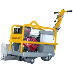
Checking the ON/OFF switch
• Turn the switch to the 'ON” ('1”
position) to start the engine. The
blade will
rotate when the engine is turned on.
• Turn the switch to the 'OFF” ('O”
position). Check that the engine
stops.
Blade Block Guard Maintenance Check
• Check that the guard is undamaged and not cracked.
Replace the guard if it has been exposed to impact or is
cracked.
• A damaged blade block assembly must be replaced to
protect the operator and the machine.
• Always check that the guard is correctly fitted before
starting the machine.
10
3.4 Roll Cage
The roll cage protects the equipment, engine, and operator from damage.
3.5 Belt Guard
The belt guard protects the operator from rotating sheaves and the belt.
3.6 Sheave Guard
The sheave guard protects the operator from rotating blade sha sheaves.
Checking The Belt Guard
• Make sure the belt guard is undamaged and not
cracked. Replace the guard if it has been exposed to
impact or is cracked.
• Always check that the belt guard is correctly fitted
before starting the machine.
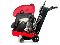
Checking The Sheave Guard
• Check that the guard, located underneath the
machine, is undamaged and not
cracked. Replace the sheave guard if it has been
exposed to impact or is cracked.
• Always check that the guard is correctly fitted
before starting the machine.
11
4. ASSEMBLY GUIDE
4.1 Unpacking
5.1.1 Remove the Early Entry Green
Concrete Saw from the package. The saw
should be lied from the center handle on
the roll cage.
4.1.2 Discard or recycle the packing
material per your regional laws. No
diamond cutting blade or skid is included
with the saw.
4.1.3 Purchase the appropriate blade and
skid plate from our website at
www.tomahawk-power.com or your local
Tomahawk Power Construction Product
dealer.
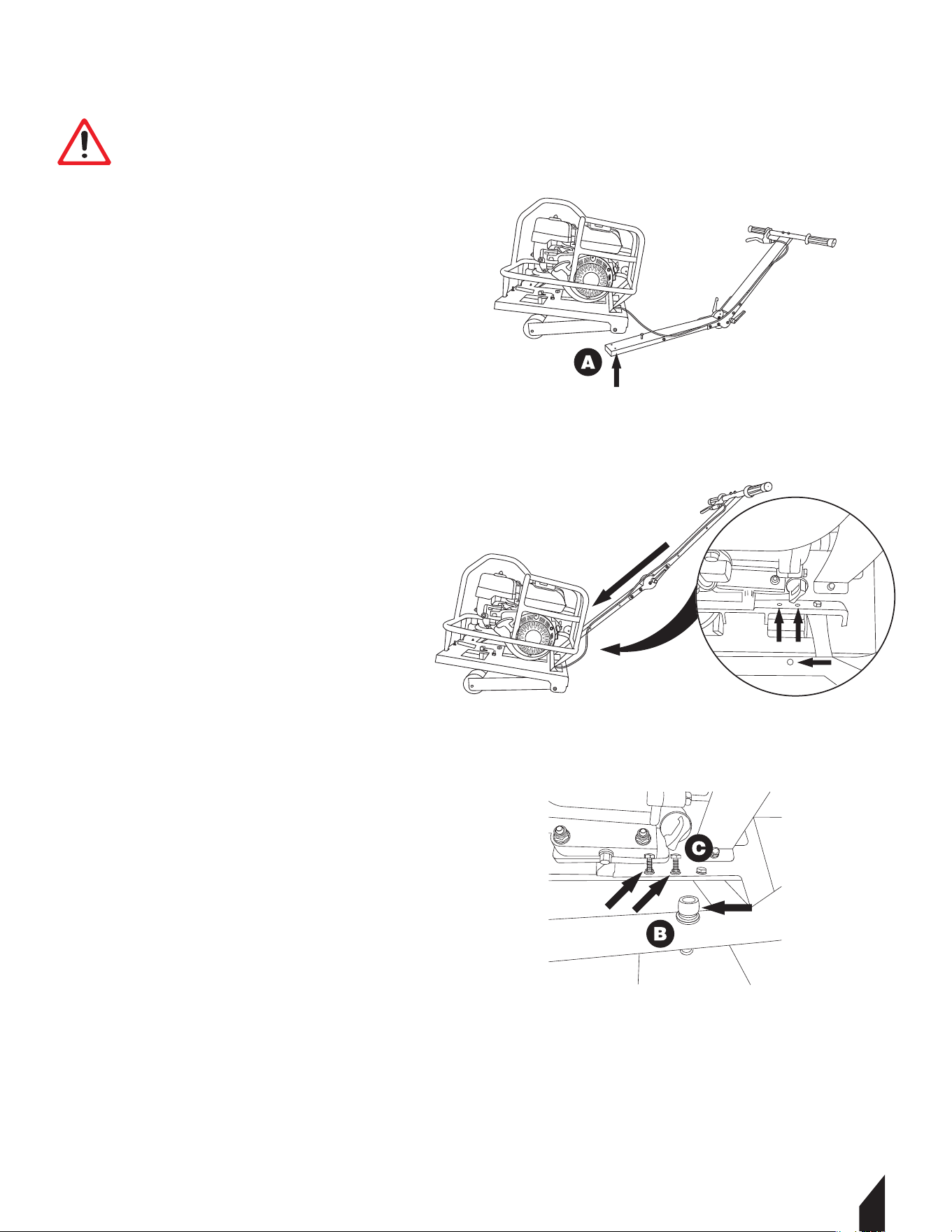
4.2 Handle Assembly
5.1.1 Loosen the bolts (A) at the base of the
handles using a 10mm wrench.
4.1.1 Mount the handles to the back of the
saw’s roll cage (B) with the longer screw and
a 5mm allen wrench.
4.1.1 Connect the base of the handles by
fastening the bolts and washers (C) – secure
the bolts in place with a 10mm wrench.
WARNING
The engine should be switched off during operations described in this chapter unless
otherwise stated. Remove the ignition cable from the spark plug to prevent accidental
engine starting.
12
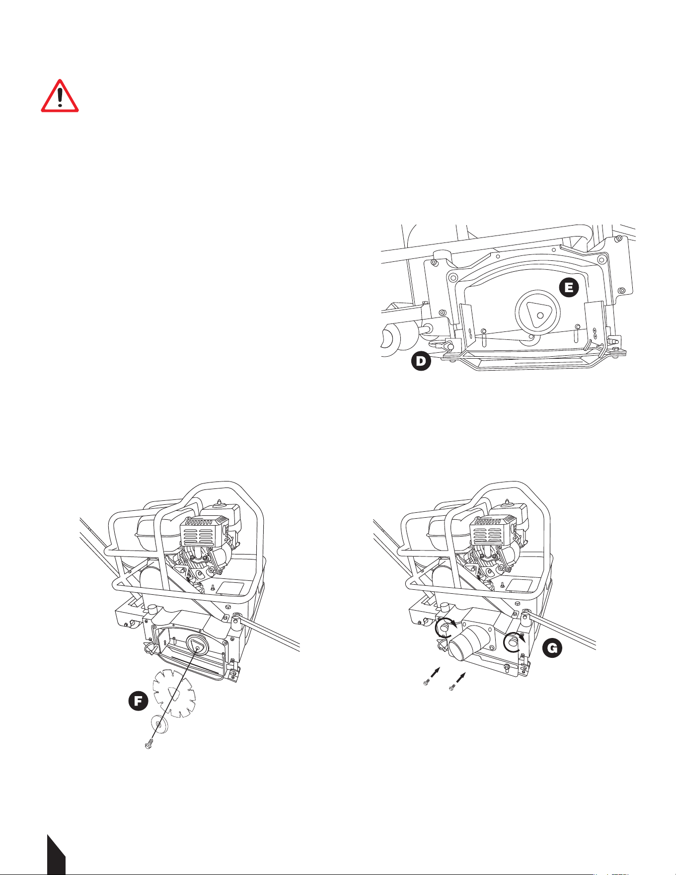
4.3 Fit the Blade
4.3.1 Insert the locking pin (D).
4.3.2 Remove the blade sha bolt and outer blade
flange (E) using a 17mm socket or wrench.
4.3.3 Next, mount the blade (F) on the blade sha
and then attach the outer blade flange.
4.3.4 Tighten the bolt firmly using the 17mm socket
or wrench.
4.3.5 Mount the blade block guard (G) with vacuum
port. Tighten with a 10mm wrench until fully seated against the blade block. (If you are
replacing the blade, thoroughly clean the concrete from the sha, blade block and guard).
WARNING
Inspect the blade for damage, cracks, loss of segments, warping, overheating, excessive
wear or a damaged tri-arbor hole. If the blade shows any of these problems, safely
discard the blade.
Make sure the blade is marked with a maximum operating speed greater than 4450 rpm.
Inspect blade flanges for damage, excessive wear and cleanliness. The blade should fit
snugly on the clean, undamaged tri-arbor sha.
13
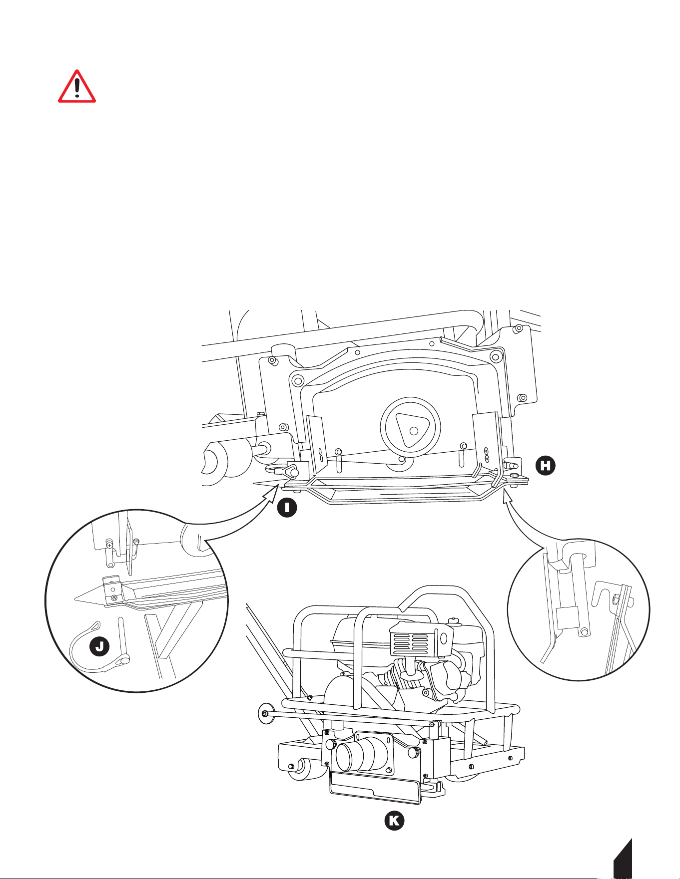
WARNING
The patented skid plate is the most important part of the Early Entry Green Concrete
Saw system. If it is bent, twisted, or damaged, cuts may spall or cause ravelling. Store
skid plates carefully and install them properly. Install a new skid plate with each new
blade. Never reuse skid plates.
4.4 Installing a New Skid Plate
4.4.1 Hook the front of the skid plate (H) on the front blade block sha pin.
4.4.2 Connect the rear blade block sha (I) and the rear of the skid plate by installing the
locking pin (J).
4.4.3 Li the front and rear of the skid plate to ensure the blade slides freely through the skid
plate.
4.4.4 Ensure the lexan cover (K) moves freely up and down.

14
5. FUEL HANDLING
5.1 Fueling
5.1.1 Use unleaded gasoline with an octane rating of 87 or higher.
5.1.2 Unleaded gasoline with more than 10% ethanol should not be used. It may cause
starting and/or performance problems. It may also damage metal, rubber, and plastic parts
of the fuel system, as well as posing a fire hazard.
5.1.3 DO NOT use gasoline containing methanol.
5.1.4 DO NOT use fuel that is older than 30 days. Old fuel can cause running problems as
well as fuel system damage
5.2 Refueling
When refueling, it's essential to take the equipment out of the vehicle and refuel it on the
ground; if this isn't feasible, use a portable container instead of a petrol dispenser nozzle.
Always use approved gasoline containers and never refuel inside a vehicle; place the con-
tainer on the ground, away from the vehicle during filling. Maintain nozzle contact with the
fuel tank or container opening throughout the refueling process, avoiding the use of nozzle
lock-open devices. Additionally, properly dispose of used engine oil, antifreeze, and similar
substances at a workshop or designated disposal site to prevent environmental and health
hazards.
6. OPERATION
6.1 Before Starting
• Make sure the engine is filled with SAE10W30 4 Stroke Oil and 89 Octane Fuel. If the oil
and fuel levels are too low, the low oil sensor will not allow the engine to start
WARNING
Running an engine in a confined or badly ventilated area can result in death due to
asphyxiation or carbon monoxide poisoning. Use fans to ensure proper air circulation
when working in trenches or ditches deeper than one meter.
Fuel and fumes are highly flammable and can cause serious injury when inhaled or
allowed to come in contact with the skin. For this reason, observe caution when
handling fuel and make sure there is adequate ventilation.
The exhaust fumes from the engine are hot and may contain sparks which can start a
fire. Never start the machine indoors or near combustible material!
Do not smoke and do not place any hot objects in the vicinity of fuel.
WARNING
Always stop the engine and allow it to cool for a few minutes before refueling. Refuel
the engine in a well ventilated area. Never fuel the engine indoors.
When refueling, open the fuel cap slowly so that any excess pressure is released gently.
Never overfill the fuel tank.
Clean the area around the fuel cap.
Tighten the fuel cap carefully aer refueling. Check for fuel leaks.
Failure to follow these guidelines may lead to a fire.
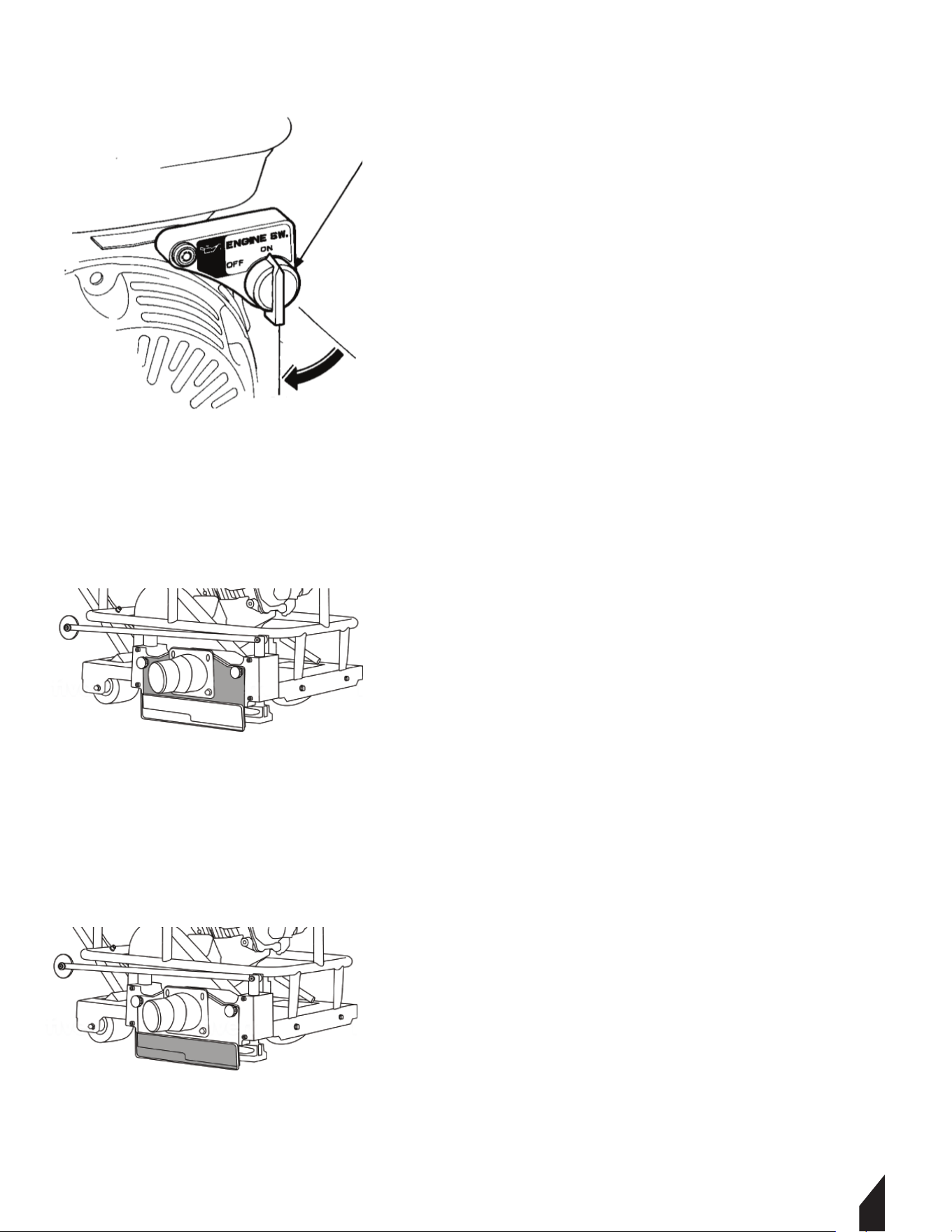
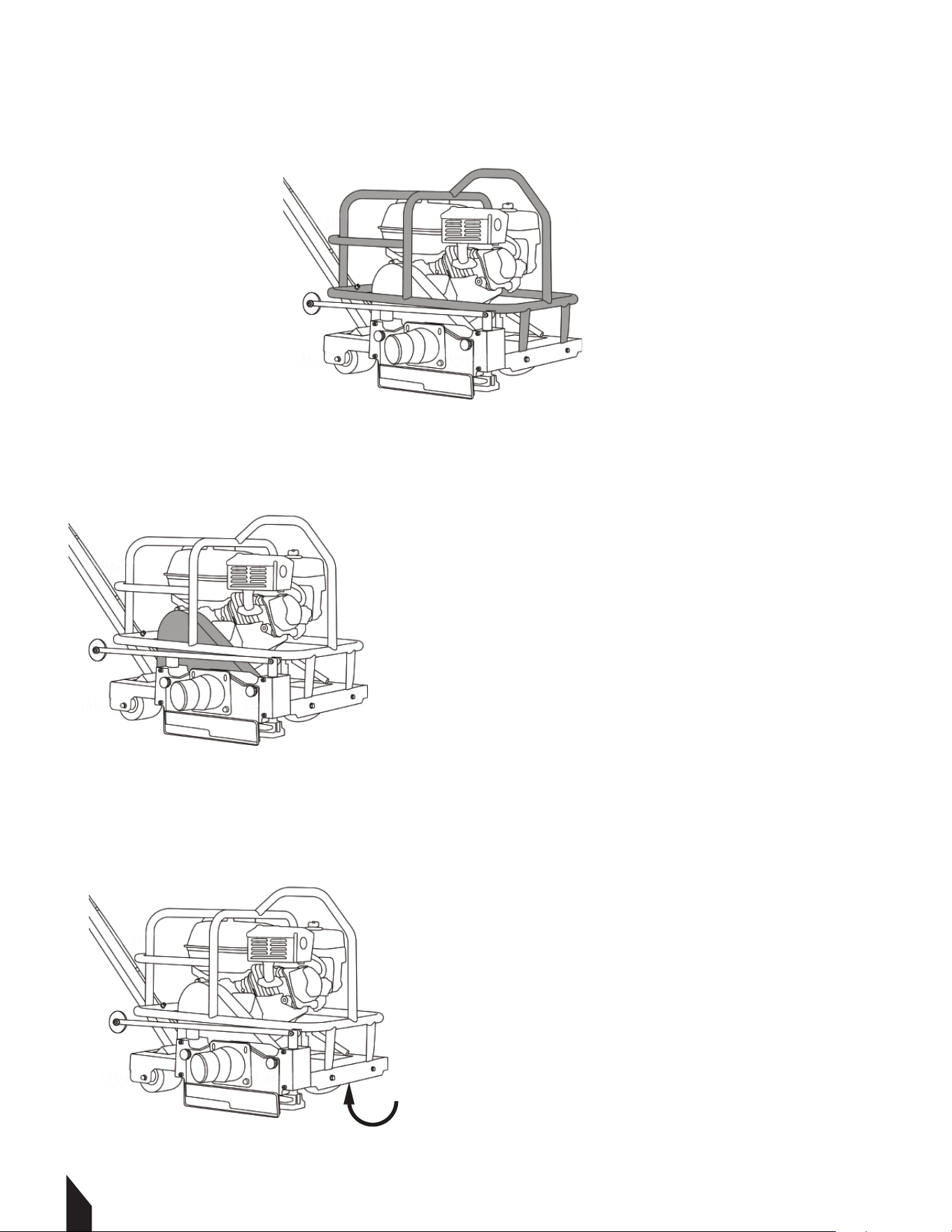
6.1 Before Starting Continued
• Check that the handle is in a full upright position and pinned.
• Check that the front guide is rotated to the FORWARD position.
•
•
•
•
•
•
•
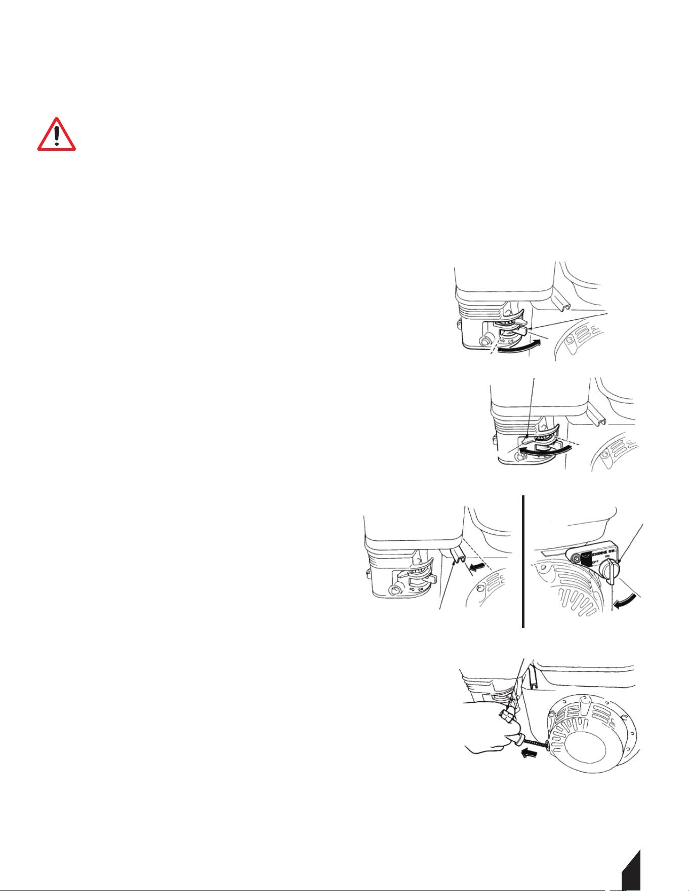
• To raise the blade, push down on the handle bar with
both hands to the full and locked position.
• Move the engine throttle lever to the full closed position.
• Turn the switch to the 'OFF” ('O” position).
• Close the fuel valve.
15
WARNING
Please read the operator’s manual carefully and make sure you understand the
instructions before using the machine.
Wear personal protective equipment. Refer to the instructions under the ”Personal
Protective Equipment” heading.
Make sure no unauthorized persons are in the working area, otherwise there is a risk of
serious personal injury.
Check that the guards are mounted correctly and do not show any signs of damage. See
instructions in the section "SAFETY EQUIPMENT" and ”ASSEMBLY GUIDE”.
STARTER GRIP
THROTTLE LEVER
ON
FUEL LEVER
CHOKE LEVER
CLOSE
ON
16
• Open the engine throttle lever to full open position for maximum engine speed.
• Line up the saw with the cut line using the white wheel on the front guide and the
triangle pointer on the back of the blade block.
• To lower the blade into the concrete slowly, push down on the saw handle and pull the
blade release lever.
• Push the saw forward to cut, keeping the front guide wheel in the cut line.
• Push the saw at about half speed for the first 50 feet to allow the blade to develop good
diamond exposure.
• Increase the forward speed of the saw until the blade and engine are working at
maximum efficiency. DO NOT force the saw.
• When approaching a wall, raise the front guide and use the triangle guide at the back of
the blade block to cut the last few feet.
• DO NOT hit the blade block assembly against any
object. Damage may result.
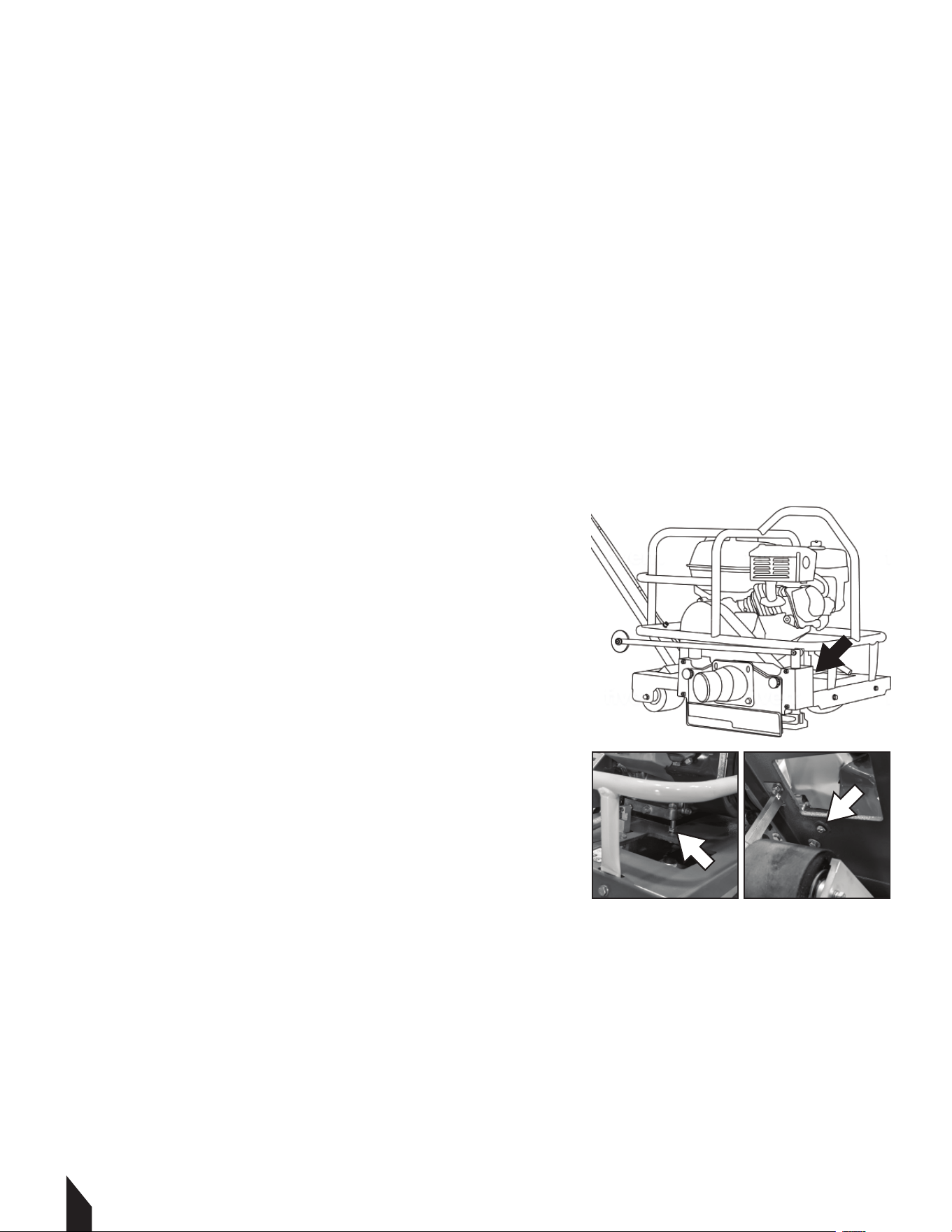
The Tomahawk Early Entry Concrete Saws’ default blade
setting is adjusted to the max blade depth of 1-3/16”
(ASTM Standard Specification for Portland Cement). If a
shallower cut is desired, follow these steps:
• Loosen the depth adjustment nut (1) above the front
right wheel, counter-clockwise with a 13mm wrench.
• Turn the depth stop adjustment bolt (2) clockwise with
a Size 5 Metric Allen wrench. Each full revolution of the
bolt will reduce the cut depth by 1/8".
• Make sure the rear wheels are flat on the ground by
pushing down on the rear of main frame.
• Follow an existing saw joint cut for approximately one
foot to confirm that the proper/desired cut is achieved.
21

17
7. BASIC CUTTING TECHNIQUES
7.1 Sawing Contraction Joints

1718
7.1 Sawing Contraction Joints Continued
7.2 Maximizing The Early Entry System
¡
Concrete thickness, mm(in.) Maximum spacing, m (.)
90 (3.5) 2,4 (8)
100, 114 (4, 4.5) 3,0 (10)
125, 140 (5, 5.5) 3,6 (12)
150 (6) or greater 4,5 (15)
19
¡
¢

1720
9. MAINTENANCE
9.1 Additional Engine Servicing
Please see the engine Operator’s Manual for additional information about servicing the
engine.
The manual also contains specific information about specifications, tune-up parts, engine
warranty, emission compliance, and more.
9.2 Replacement Parts
• For replacement parts and technical questions visit www.tomahawk-power.com or
scan the QR code on the front of this manual.
• Not all equipment components are available for replacement. The illustrations within
this manual are a convenient reference to the location and position of parts in the
assembly sequence.
• When ordering parts, the following will be required: model number, serial number/lot
date code, and description.
• The distributor reserves the right to make design changes and/or improvements to
product lines and manuals without notice.

21
9.3 Maintenance Schedule
Maintain the screed in accordance with the following recommended procedures. Refer to
the engine manufacturer’s instruction manual for additional information about engine
maintenance. The following chart is based on a normal operation schedule.
Check the fuel level
Clean the cylinder head
Replace the spark plug
Check the engine oil level
Inspect the fuel lines
Inspect the air filter and replace if
needed
Check and tighten the external
hardware
Change the engine oil
Check and clean the spark plug
Clean the fuel strainer
Check and adjust the valve
clearance
Change the engine oil
Clean the air filter
DAILY
BEFORE
STARTING
AFTER
FIRST 20
HOURS OR 3
MONTHS
AFTER
FIRST 50
HOURS OR 6
MONTHS
AFTER
FIRST 100
HOURS OR
EVERY YEAR
AFTER
FIRST 200
HOURS OR
EVERY
2 YEARS

17
22
10. TROUBLESHOOTING
Please check the list below before addressing the problems to servicing personnel
including local dealer. And if the problem continues aer the troubleshooting as described
below, call your local dealer for future assistance.
Check to see if the diamond blade is worn out, glazed, warped or damaged.
Ensure skid plate moves freely up and down the entire sha length without contacting the diamond
blade.
Check skid plate for excessive wear or gap around the diamond blade.
Check bottom of skid plate for metal burrs or irregularities.
Ensure skid plate is not twisted or bent.
Check lexan covers for free movement up and down.
Ensure there is spring down pressure at each end of the skid plate.
Do not twist or move the saw sideways while cutting. Make gradual changes in pressure on the
handlebar to control the saw in the cut.
Check that the engine is running properly and at full throttle.
Check belt and belt idler for proper tension.
Ensure the diamond blade is properly mounted and secured with clean flanges.
Ensure that the diamond blade is the correct specification for your area.
Ensure the slab is in clean with no debris that could raise the skid plate or saw while cutting.
Use Tomahawk Power joint protectors at all cut intersections.
Clean excess concrete debris from the blade block assembly.
Check that the scrapers in the blade block are not bent or binding.
Ensure that the blade block shas are not bent or damaged.
Check that the front guide is properly aligned with the center of the diamond blade.
Check to see if the diamond blade is worn out, glazed, warped or damaged.
Do not twist or move the saw sideways while cutting. Make gradual changes in pressure on the
handlebar to control the saw in the cut
Ensure that all wheels rolls freely and smoothly.
Do not force the saw. Allow the diamond blade to cut at its own rate of speed.
Check the skid plate for damage or burrs.
Check if there is fuel in the tank and it is the correct fuel. Make sure there is no water in the fuel.
Check if the fuel valve is turned to the 'on” position.
Check if the ON/OFF switch is in the 'ON” position.
Check that the spark plug wire is connected to the spark plug.
Engine is flooded. Adjust the choke per the engine owner’s manual.
Check the choke is in the 'ON” position for cold starts. Adjust the choke per the engine owner’s manual.
Oil level is too low. Engine is equipped with an oil alert system that will not let the engine start unless
the engine oil level is within the correct range.
Check that air cleaner is not dirty or plugged.
Check that the blade sha rotates freely and no concrete has built up in the blade block.
Check if there is fuel in the tank and it is the correct fuel. Make sure there is no water in the fuel.
Oil level is too low. Engine is equipped with an oil alert system that will not let the engine start unless
the engine oil level is within the correct range.
Check that air cleaner is not dirty or plugged.
Check that spark plug is clean and properly gapped.
Check that throttle lever is properly set.
Check the choke is in the 'ON” position for cold starts. Adjust the choke per the engine owner’s manual.
Saw is spalling
and ravelling
cut
Saw pulls to
one side
while sawing
Engine does
not start
Engine runs
rough, back
fires or can not
reach full
speed.
23
Parts Manual
6” EARLY ENTRY
CONCRETE SAW
MODEL NUMBER: TFS6H
24
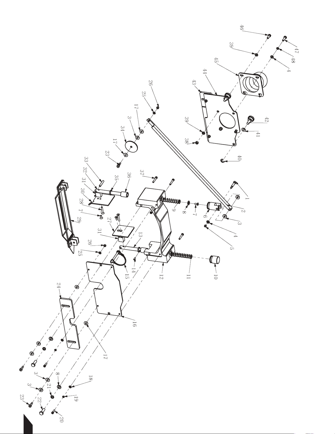
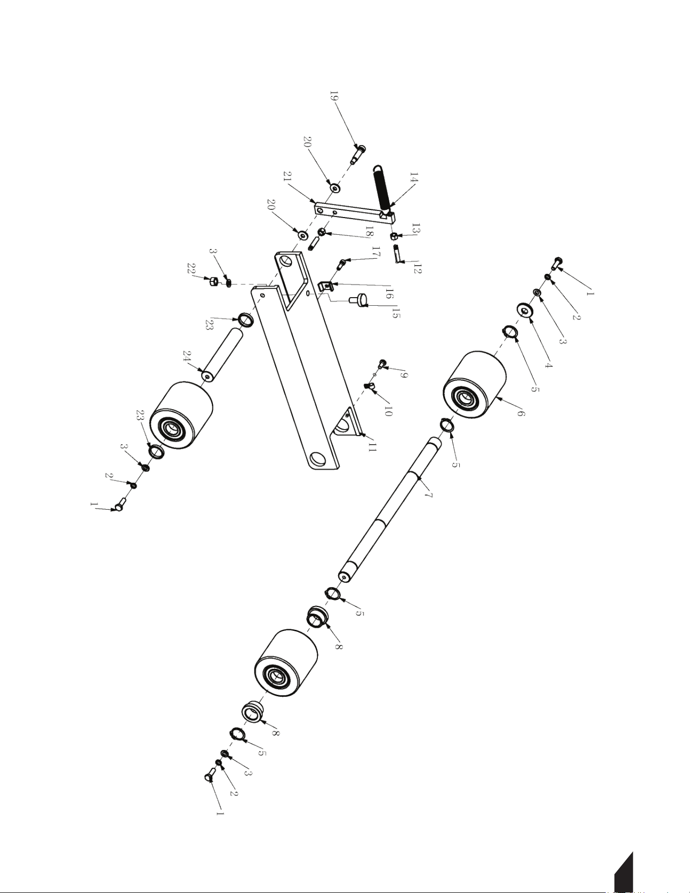
BLADE COVER ASSEMBLY

25
No. Description Drawing No. Qty
1 Shoulder Screw M5xΦ6x25 16052510 1
2 Pointer 1906-00022-1 1
3 Spacer 1906-00001-4 11
4 Washer M6 11060010 3
5 Lock Nut M5 13050011 1
6 Front Cap, Rod 1906-00021-1 1
7 Allen Screw M5x12 16051221 3
8 Washer M8 11080000 3
9 Spring (Long) 1906-00016-4 1
10 Rare Cap, Rod 1906-00039-1 1
11 Spring (Short) 1906-00035-4 1
12 Blade Cover 1906-00041-2 1
13 Rare Rod 1906-00043-1 1
14 Spring Pin Φ3x14 19031401 1
15 D Pin 1906-00014-4 1
16 Inner Shield 1906-00030-2 1
17 Spacer 1906-00015-4 6
18 Washer M5 11050010 2
19 Spring Washer M5 12050010 2
20 Allen Screw M5x16 16051620 2
21 Spring Washer M8 12080000 2
22 Bolt M8x25 15080250 2
23 Bolt M5xΦ6x10 16051010 5
24 Inner Plastic Shield 1906-00046-4 1
25 Washer M5 11050000 5
26 Lock Nut M5 13050001 5
27 Rare Shield 1906-00045-2 1
28 Allen Screw M5x30 16053021 2
29 Skid 1906-03000-4 1
30 Front Shield 1906-00018-2 1
31 Spacer, Front Shield 1906-00013-2 1
32 Front Rod 1906-00031-1 1
33 Pin Φ6.35x32 1906.353202 1
34 Guide Wheel 1906-00047-4 1
35 Oil Sealing Φ19xΦ12x3 1906-00048-4 2
36 Bushing 1906-00024-1 2
37 Allen Screw M5x30 16053020 5
38 Lock Nut M6 13060001 2
39 Washer M6 11060000 4
40 Circlip Φ8 18080003 2
BLADE COVER ASSEMBLY

No. Description Drawing No. Qty
41 Wave Washer M8x16x0.8 14080001 2
42 Bolt M8x20 16082008 2
43 Outside Plastic Shield 1906-00034-4 1
44 Outside Shield 1906-00040-3 1
45 Vac Port 1906-00051-4 1
46 Bolt M6x16 15060160 2
47 Bolt M6x20 15062011 2
48 Spring Washer M6 12060010 2
BLADE COVER ASSEMBLY
26
ᒿ 〠 മ 䭟⡷䖤ᙫᡀᮠ䟿 ༷⌘
㷪ṃ0[
ᒣෛ0[[[[
ᒣෛ0
ᑖ・ᔿᓗ䖤8&3 8&3
䱢ᶮ㷪⇽0
㍗ᇊ㷪䪹0[
&*&䭟⡷䖤Ⳟᑖ䖞
ശཤᒣ䭞[ $
&*&䭟⡷䖤✺᧕㓴Ԧ
&*&䭟⡷ረ
&*&䭟⡷ཆᶯ
⌅ޠ䶒㷪ṃ0[
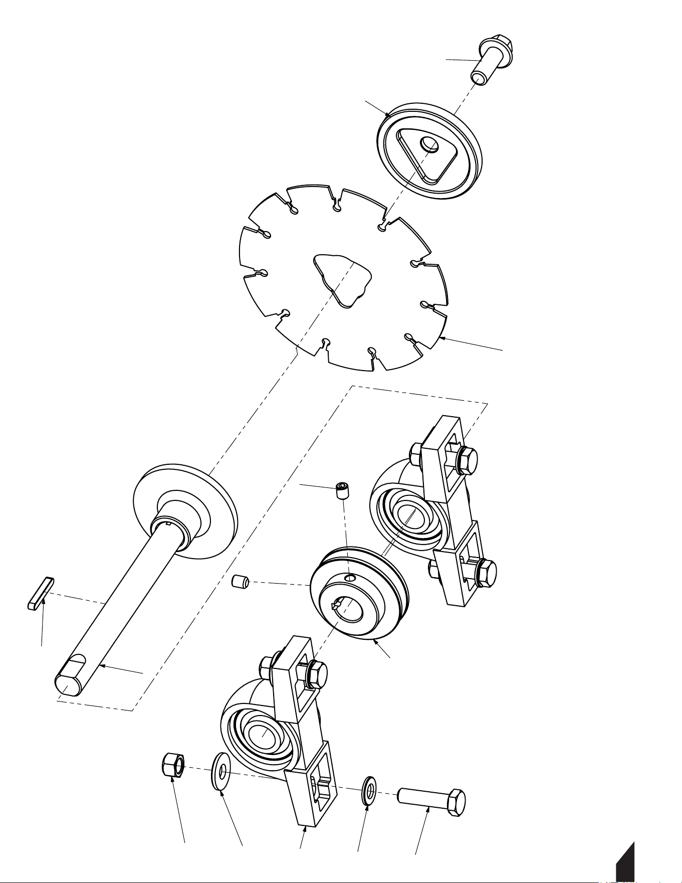
BLADE SHAFT ASSEMBLY
27

No. Description Drawing No. Qty
1 Bolt M10x40 15100400 4
2 Washer M10x25x3(10x26x3) 11102503 4
3 Washer M10 11100000 4
4 Bearing UCP204 21UCP204 2
5 Lock Nut M10 13100001 4
6 Set Screw M8x10 16081005 2
7 Driven Pulley 1906-00006-4 1
8 Key 5x35 12050535A 1
9 Blade Shaft 1906-04000-3 1
10 Blade 8“ 1906-00050-4 1
11 Flange (Outside) 1906-00036-1 1
12 Bolt M12x30 15123002 1
BLADE SHAFT ASSEMBLY
1728
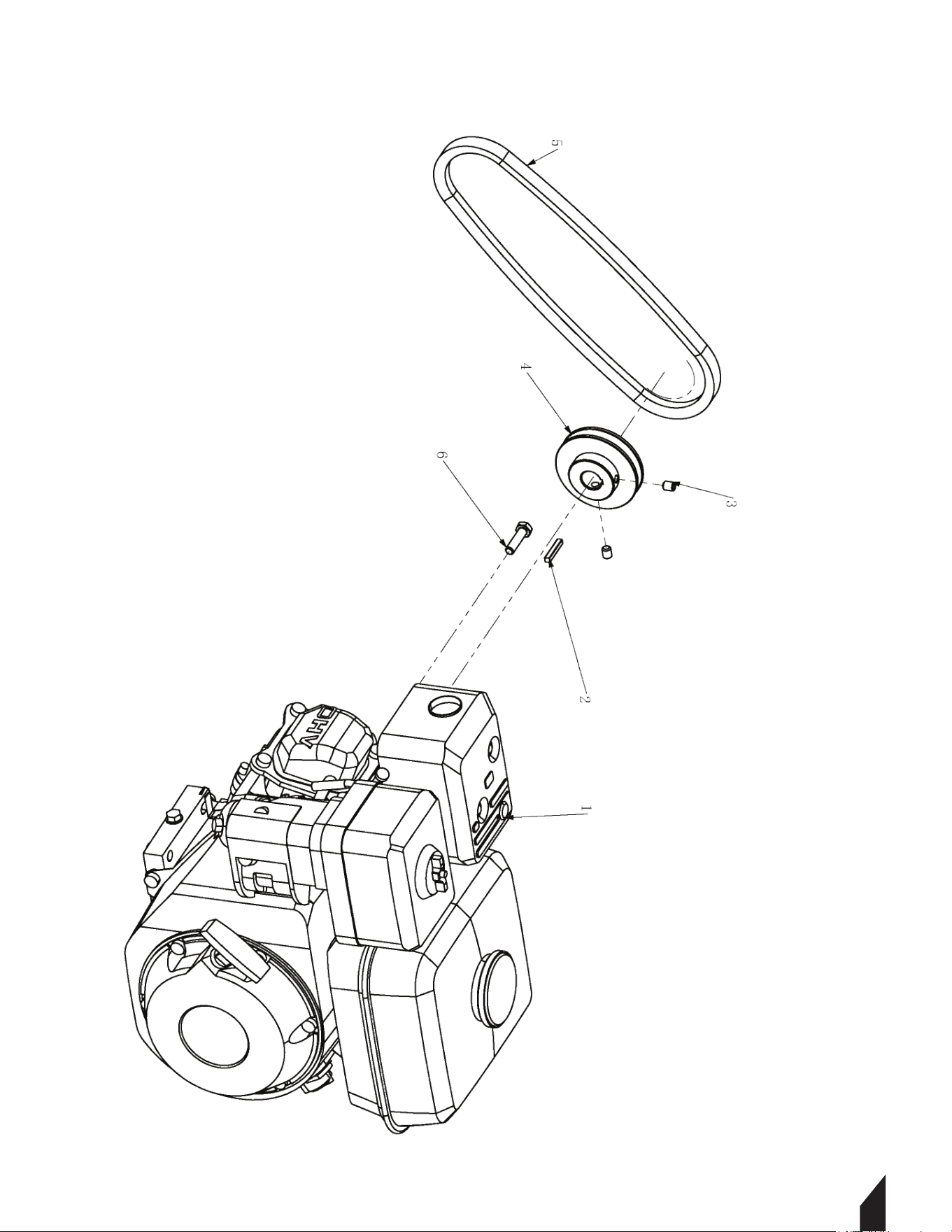
ENGINE ASSEMBLY
29

No. Description Drawing No. Qty
1 Engine 25120002 1
2 Key 4.76x30 204.7630C 1
3 Set Screw M8x10 16081005 2
4 Drive Pulley 1906-00005-4 1
5 Belt 27XPZ7103VX280 1
6 Bolt 5/16-24x1-1/4 15080350Y 1
ENGINE ASSEMBLY
1730
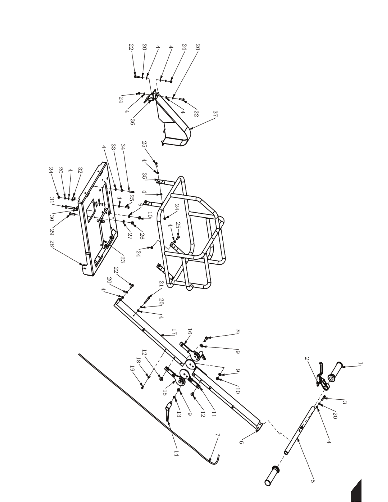
MAIN BODY ASSEMBLY
31

17
32
No. Description Drawing No. Qty
1 Handle Grip 70220000 2
2 Brake Grip 1906-00011-4 1
3 Allen Screw M6x30 16063020 2
4 Washer M6 11060010 21
5 Handle Bar 1906-00044-1 1
6 Upper Handle 1906-00038-1 1
7 Wire 1906-00009-4 1
8 Bolt M8x25 15080250 2
9 Washer M8 11080000 10
10 Lock Nut M8 13080001 6
11 Connecting Plate, Upper 1906-00054-2 2
12 Allen Screw M8x16 16081604 8
13 Spring Washer M8 12080000 2
14 Locking Handle M8x16 28080164 2
15 Connecting Plate, Lower Left 1906-00053-2 1
16 Connecting Plate, Lower Right 1906-00052-2 1
17 Lower Handle 1906-00023-1 1
18 Wire Clip 1906-00002-4 4
19 Bolt M5x12 16051201 4
20 Spring Washer M6 12060010 11
21 Allen Screw M6x50 16065020 1
22 Bolt M6x25 15062511 4
23 Rubber Engine Spacer 1906-00010-4 1
24 Lock Nut M6 13060011 7
25 Bolt M6x20 15062011 7
26 Nut M8 13080012 1
27 Washer M8 11080010 1
28 Engine Base 1906-00032-1 1
29 Allen Screw M8x30 16083019 1
30 Washer M8x22x2 11082202 4
31 Bolt M8x55 15080550 4
32 Anchor, Position Bar 1906-00027-2 1
33 Nut M6 13060012 1
34 Bolt M6x30 1906-00003-4 1
35 Frame 1906-05000-3 1
36 Lower Shield 1906-00019-2 1
37 Belt Cover 1906-00029-2 1
MAIN BODY ASSEMBLY
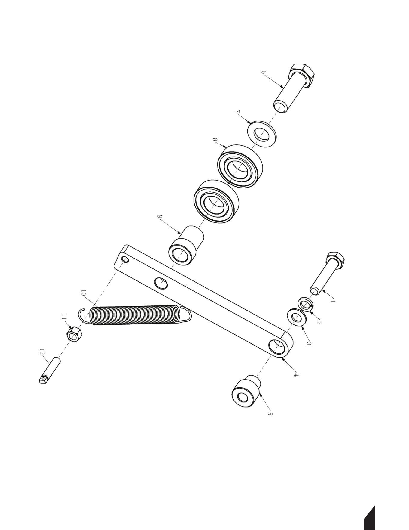
TENSIONER
33

No. Description Drawing No. Qty
1 Bolt M8x40 15080400 1
2 Spring Washer M8 12080010 1
3 Washer M8 11080010 1
4 Tensioner Rod 1906-01001-2 1
5 Bushing 1906-01002-1 1
6 Bolt M12x40 15120400 1
7 Washer M12 11120000 1
8 Bearing 6003-2R 216003-2Z 2
9 Bushing 1906-01003-1 1
10 Spring 1906-00008-4 1
11 Nut M6 13060012 1
12 Bolt M6x30 1906-00003-4 1
TENSIONER
34
ADJUSTMENT SYSTEM
35

No. Description Drawing No. Qty
1 Bolt M6x20 15062011 3
2 Spring Washer M6 12060010 3
3 Washer M6 11060010 4
4 Washer M10x25x3(10x26x3) 11102503 1
5 Circlip Φ20 18200001 4
6 Wheel 1906-02000-1 3
7 Rare Shaft 1906-00017-1 1
8 Nylon Bushing 1906-00020-1 2
9 Bolt M5x12 16051201 1
10 Wire Clip 1906-00002-4 1
11 Carriage 1906-00028-1 1
12 Bolt M6x30 1906-00003-4 2
13 Nut M6 13060000 1
14 Spring 1906-00007-4 1
15 Bolt M8x18 16081823 1
16 Wire Clip 1906-00012-2 1
17 Allen Screw M5x16 16051620 1
18 Nut M6 13060012 1
19 Bolt M6xΦ8x25 16062510 1
20 Spacer 1906-00001-4 2
21 Position Bar 1906-00025-1 1
22 Lock Nut M8 13080001 1
23 Spacer 1906-00026-2 2
24 Front Shaft 1906-00042-1 1
ADJUSTMENT SYSTEM
36

37
NEVER PUMP
NEVER LOSE PRESSURE
Lose the manual pump and gain the power to spray
or less while maintaining constant, adjustable pressure from 50-435 PSI with
your ideal concrete sealant, cure, top cast, form release, and more!
27
24
Item #: TCS6.5
6.5 GAL MOTORIZED
CONCRETE SPRAYER
www.tomahawk-power.com

1.6HP Backpack Concrete Vibrator
Part#: TVIBH + TVW10-P
1.6 HP Honda GX35 engine
Consolidation with speeds of 10,000-12,000 VPM
Quick Connect centrifugal clutch vibrator
1” and 2” Diameter Whips Available in 10ft Length
3 Year Engine Warranty & 1 Year Product Warranty
8” Gas Powered Concrete Scarifier
Part#: TSCAR8H
5.5 HP Honda GX160 Engine
Remove traffic lines at 800 - 1,000 linear ft/hr
Tungsten Carbide Blade Kit Available
OSHA approved dust port for silica vacuum removal
3 Year Engine Warranty & 1 Year Product Warranty
36” & 46” Concrete Power Trowel
Part#: TPT36H/K & TPT46H/K
6 HP/14HP Kohler & 5.5HP/8.5HP Honda Engines
Adjust trowel blade pitch from 0-28°
60-115 RPM rotor speed for superior concrete finishes
Includes float pan and trowel blades
3 Year Engine Warranty & 1 Year Product Warranty
HAVE QUESTIONS?
Contact us. We’re here to help!
Email us at [email protected]
3,550 lbs/ft Vibratory Rammer
Part#: TR68H
3.6 HP Honda GXR120 Engine
Easily achieve a 100% compaction rating
3-in-One Fuel System with carburetor protection
13” x 11” plate for narrow trenches and corners
3 Year Engine Warranty & 1 Year Product Warranty
3,400 lbs/ft Plate Compactor
Part#: TPC90H
5.5 HP Honda GX160 Engine
Easily achieve a 100% compaction rating
22” x 20” cold, rolled steel beveled base plate
Includes 3.5 gallon water tank for asphalt compaction
3 Year Engine Warranty & 1 Year Product Warranty
3,000 lbs/ft Plate Compactor
Part#: TPC80 & TPC80H
6 HP Kohler CH260 & 5.5 HP Honda GX160 Engines
Easily achieve a 100% compaction rating
16.5” x 21.5” plate for narrow trenches and corners
Optional Honda Engine model: TPC80H
3 Year Engine Warranty & 1 Year Product Warranty
COMPACTION
6.5 Gal Backpack Concrete Sprayer
Part#: TCS6.5
Maintain constant, adjustable pressure up to 450 PSI
Achieve superior concrete finishes with even spraying
Spray 15,000 sq ft in less than 10 minutes
Compatible with major manufacturer wands
1 Year Product Warranty
1.6 HP Vibratory Concrete Screed
Part#: TVSA-H
1.6 HP Honda GX35 Engine
Aluminum Magnesium blades available from 8ft - 14ft
Finish concrete 4X faster than other screed methods
360° adjustable handle placement
3 Year Engine Warranty & 1 Year Product Warranty
6” Early Entry Green Concrete Saw
Part#: TFS6H
5.5 HP Honda GX160 Engine
Maximum cutting depth of 1 3/16 inches
OSHA compliant vacuum port for dust collection
Includes 6” early entry concrete blade
3 Year Engine Warranty & 1 Year Product Warranty
FINISHINGFINISHING
Ramm
er
Ramm
er

USE CODE
SAVE10
AT CHECKOUT FOR
10% OFF YOUR ORDER AT
WWW.TOMAHAWK-POWER.COM
www.tomahawk-power.com
www.tomahawk-power.com
(866) 577-4476
ASSEMBLED IN THE
PARTS SOURCED GLOBALLY
USA
INVERTER SERIESINVERTER SERIES
www.tomahawk-power.com
(866) 577-4476
3.7 Gallon 3HP Backpack Fogger
Part#: TMD14
Turbo Boosted Pump with 40ft + Horizontal Reach
Sprays 1 acre in 30 minutes
10X Faster than Manual Pump Sprayers
Converts to Leaf Blower with 200 MPH Air Velocity
1 Year Product Warranty
Commercial 38" Push Sweeper
Part#: TOS38
Collect up to 14.5 gallons of dust and debris
Can be used indoors & outdoors on wet or dry surfaces
Includes integrated airflow control and fine dust filter
Lightweight design, capable of fitting through doorways
1 Year Product Warranty
210 Amp Portable Welder Generator
Part#: TWG135Ai
Steady 50 - 135 Amp DC welding output
3300 Watt Inverter Generator
60% Duty Cycle for extended use
Suitable for welding rods from 6010 to 7024
2 Year Product Warranty
210 Amp Portable Welder Generator
Part#: TWG210A
Steady 50 - 210 Amp DC welding output
2000 Watt Inverter Generator
60% Duty Cycle for extended use
Suitable for welding rods from 6010 to 7024
2 Year Product Warranty
INVERTER SERIES
Part#: TG2000i
2000 Max Watts, 1600 Rated Watts
Run Time of 8 hours on 1 gallon of gas
OSHA and GFCI Compliant
Parallel technology capable for double the power
2 Year Product Warranty
2000 Watt Inverter Generator
5 Gallon Backpack Power Sprayer
Part#: TPS25
Reach Up to 30ft Horizontal Reach
Sprays acres in 10 minutes
10X Faster than Manual Pump Sprayers
50-435 Adjustable PSI Commercial Grade Pump
1 Year Product Warranty
4.75 Gallon Battery Power Sprayer
Part#: eTPS18
Reach Up to 30ft Horizontal Reach
Sprays 6000 sq ft in 10 minutes
10X Faster than Manual Pump Sprayers
70 PSI Commercial Grade Pump
1 Year Product Warranty
4 Gal. Motorized Fertilizer Spreader
Part#: TGS30
Reach up to 30ft Horizontally
Sprays 1 acre in 30 minutes
20X Faster than push spreaders
Converts to Leaf Blower with 200 MPH Air Velocity
1 Year Product Warranty
3” Full Trash Water Pump
Part#: TW3H
Moves liquids at a rate up to 375 gal/min
Handle solids up to 1.5"
Silicone carbide seals and a chrome plated volute
8 HP engine protected by rugged all purpose frame
3 Year Engine Warranty & 1 Year Product Warranty
AND MORE GENERATORSWELDING / POWER
INVERTER SERIES
Part#: TG2000i
2000 Max Watts, 1600 Rated Watts
Run Time of 8 hours on 1 gallon of gas
OSHA and GFCI Compliant
Parallel technology capable for double the power
2 Year Product Warranty
2000 Watt Inverter Generator
AND MORE POWER / WELDINGPEST CONTROL
ASSEMBLED IN THE
PARTS SOURCED GLOBALLY
USA
* All coupons in this manual are valid only for orders placed on www.tomahawk-power.com, unless otherwise noted. Coupon codes
may only be used once per customer and may not be combined with any other offer. Coupons may expire at any time without notice.

Tomahawk understands to keep a job-site running smoothly the proper equipment and
spare parts are needed at the drop of a hat. With same day shipping and faster
delivery times, count on Tomahawk to keep you powered throughout the day! With
long lasting parts and engines, Tomahawk equipment will be the star of your fleet for
years to come. Visit www.tomahawk-power.com to get started today!
Power Your World
FACEBOOK
facebook.com/TomahawkPowerUSA
YOUTUBE
youtube.com/TomahawkPower
INSTAGRAM
@tomahawkpower
TOMAHAWK®, LLC
San Diego, CA
Sales Support
(866) 577-4476
Equipment Support
(866) 577-4476
www.tomahawk-power.com