44
(2x)
40
1
2
3
4
22
23
25
29
5
20
37
38
39
7
(4x)
24
7
(2x)
8
9
10
11
17
16
21
36
35
31
34
33
32
18
57
46
(2x)
27
26
79
(3x)
70
47
(3x)
50
(3x)
63
(9x)
19
76
68
64
65
78
63
69
66
67(2x)
58
59
62
60
51
(2x)
16 17 18
19 20 40
84
31 32 33
34 35 36
86
7 8 9
10 21
82
1 2
3
89
64 65
66 69
88
46 57 62
63 67 77
78 79
80
51
93
44
87
37
38
92
58
59
90
7
83
47 50
70 79
85
63
68
91
77
74
4 22
23 24
94
26
27
81
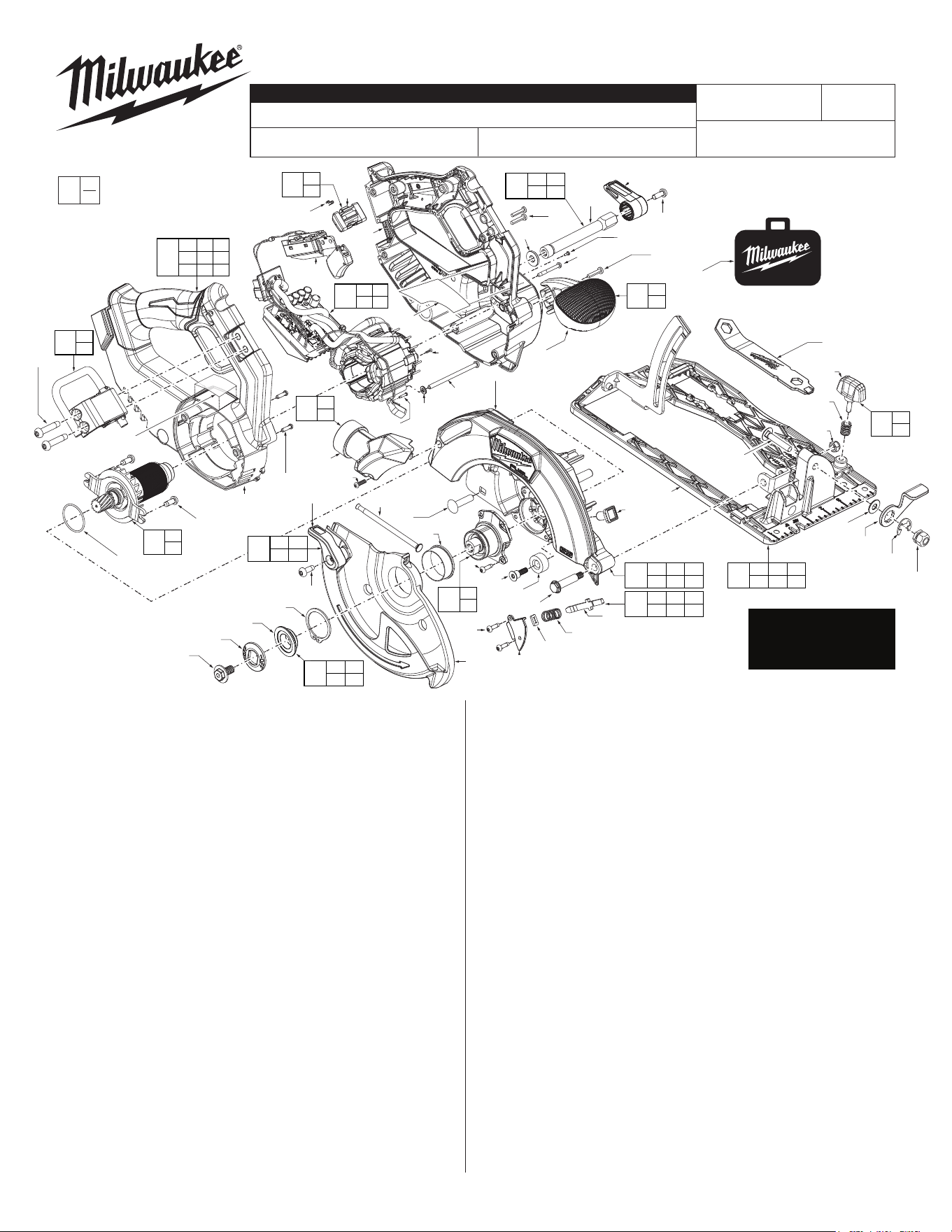
FIG. PART NO. DESCRIPTION OF PART NO. REQ.
1
---------------
Flange Bolt (1)
2
---------------
Outer Flange (1)
3 43-34-0790 Inner Flange (1)
4
---------------
External Retaining Ring (1)
5 31-15-9005 Sleeve Ring (1)
7 06-82-5285 #6-32 T-15 Pan Hd. Screw (6)
8
---------------
Spindle Lock Cover (1)
9 45-06-1260 Felt Seal (1)
10 40-50-8046 Spindle Lock Spring (1)
11
---------------
Spindle Lock Plate (1)
16 45-04-0485 M4 x .7 Pan Hd. Torx T-20 Taptite Screw (1)
17 42-38-0224 Rubber Bumper (1)
18
---------------
Pivot Shoulder Bolt (1)
19
---------------
Upper Guard Gearcase (1)
20
---------------
Hex Nut (1)
21
---------------
Spindle Lock Button (1)
22 06-82-5314 #10-24 Pan Hd. Torx T-25 Taptite Screw (1)
23
---------------
Lower Guard Lever (1)
24
---------------
Lower Guard (1)
25 49-68-5212 Guard Spring (1)
26 05-78-1005 MM3.5 x 12mm Philips Screw (1)
27
---------------
Dust Port (1)
29 06-10-0110 Carriage Bolt (1)
31
---------------
Hex Nut (1)
32
---------------
E-Ring (1)
33
---------------
Bevel Lever (1)
34
---------------
Washer (1)
35 06-10-0025 M6 x 1 Bevel Machine Screw (1)
36
---------------
Shoe Assembly (1)
37 40-50-0650 Rip Fence Spring (1)
38
---------------
Rip Fence Knob (1)
39 45-88-9320 Blade Bolt Wrench (1)
40
---------------
O-Ring (1)
44 05-74-1030 M5 x .8 Torx T-25 Pan. Hd. Screw (2)
46 05-78-1010 M3.5 x .6 Pan Hd. Torx T-10 Screw (2)
47 42-32-0028 M4 x .7 Pan Hd. Torx T-20 Screw (3)
48
---------------
Stator (1)
MILWAUKEE TOOL
l
www.milwaukeetool.com
13135 W. Lisbon Rd., Brookeld, WI 53005
Drwg. 3
EXAMPLE:
Component Parts (Small #)
Are Included When Ordering
The Assembly (Large #).
0
00
50 06-82-0243 M2 x 6mm Torx T-6 PT Screw (3)
51 06-82-9637 M6 x 28mm Pan Hd. Torx T-30 Screw (2)
57
---------------
Right Handle (1)
58
---------------
Button Flake (1)
59
---------------
Switch Lock Button (1)
60 23-66-0116 Switch (1)
62
---------------
Left Handle (1)
63 06-82-7470 #6-19 17mm Torx T-15 Screw (10)
64
---------------
Washer (1)
65
---------------
Depth Shaft (1)
66
---------------
Depth Adjustment Lever (1)
67 05-74-7190 M3.5 x 1.27 Pan Hd. Torx T-10 Screw (2)
68
---------------
Front Pommel (1)
69 05-78-0032 M5 x 13mm Machine Screw (1)
70
---------------
M2 x .635 Pan Hd. Torx T-6 Screw (1)
74 42-55-2743 Contractor Bag (Accessory) (1)
76 12-20-0387 Service Nameplate (1)
77 10-22-0653 Warning Label (1)
78 05-78-5320 M2.3 x 5mm Pan Hd. Torx T-6 Screw (1)
79
---------------
Washer (3)
80 31-44-7270 Handle Service Kit (1)
81 14-46-9961 Dust Tube Service Kit (1)
82 14-46-9962 Spindle Lock Service Kit (1)
83 14-47-1270 Output Gear Service Assembly (1)
84 14-46-9963 Gearcase Service Kit (1)
85 14-46-9964 PCBA & Stator Service Assembly (1)
86 45-16-3260 Shoe Service Kit (1)
87 16-01-6530 Rotor Service Assembly (1)
88 14-46-9965 Plunge Lever Service Kit (1)
89 14-46-9966 Blade Retention Service Kit (1)
90 14-46-9968 Lock-O Trigger Service Kit (1)
91 31-44-7260 Pommel Service Kit (1)
92 49-22-9940 Knob Service Kit (1)
93 14-46-9967 Rafter Hook Service Assembly (1)
94 28-41-2040 Lower Guard Service Assembly (1)
95 49-22-2731 Rip Fence (Not Shown) (1)
SEE PAGE 2 & 3 FOR
SERVICE NOTES AND
THE LUBRICATION
OF THIS TOOL
BULLETIN NO.
54-40-2795
SERVICE PARTS LIST
CATALOG NO. 2834-20
REVISED BULLETIN
SPECIFY CATALOG NO. AND SERIAL NO. WHEN ORDERING PARTS
M18 FUEL™ 7-1/4" Circular Saw
SERIAL NO.
DATE
Aug. 2025
WIRING INSTRUCTION
N90A
See Pages 3 & 4
FIG. PART NO. DESCRIPTION OF PART NO. REQ
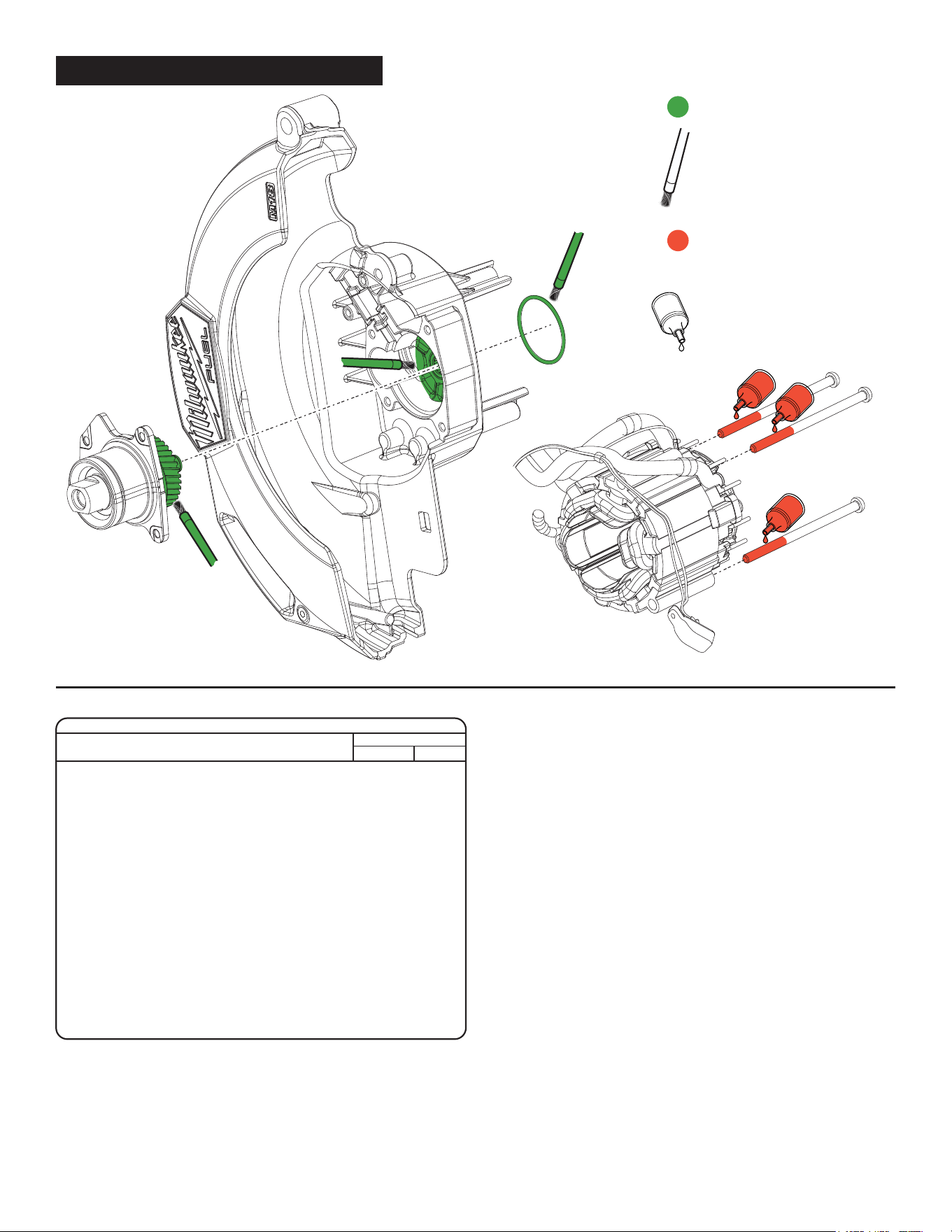
NOTE
Regarding parts to be lubricated:
Apply a light coating of grease to
all highlighted parts shown prior
to installation. Reference the
key above for grease types.
:
Type “J” Grease
(1-lb.), No. 49-08-4220
277 Red Loctite
®
,
No. 44-22-0055
NOTE
Regarding parts to receive
thread locking sealant: Place one
to two drops of the recommended
Loctite® thread locking sealant
(or the equivelant) to the threads
of parts shown prior to installation.
Gearcase
Assembly (83)
Upper Guard
Gearcase (19)
O-Ring (40)
M4 T-20
Screw (47)
Stator
SCREW TORQUE SPECIFICATIONS
SEAT TORQUE
FIG. PART NO. WHERE USED (kgf-cm) (lb-in)
1 --------------- Flange 10±1 9±1
7 06-82-5285 Output Hub/Spindle Lock Cover 20±2 17±2
16 45-04-0485 Rubber Bumper 35±4 30±3
18 --------------- Bevel Pivot 22±2 19±2
22 06-82-5314 Lower Guard Lever 35±4 30±3
31 --------------- Bevel 22±2 19±2
44 05-74-1030 Bearing Retainer Plate 30±3 26±3
46 05-78-1010 Handle 10±1 9±1
47 42-32-0028 Stator 18±2 16±2
50 06-82-0243 Hall Board 2.1±0.2 1.8±0.2
51 06-82-9637 Rafter Hook Bracket 28±3 24±3
60 23-66-0116 Switch 10±1 9±1
63 06-82-7470 Left Handle 11±1 10±1
Pommel 13±2 11±2
65 --------------- Carriage Bolt 40±4 35±3
67 05-74-7190 Left Handle 13±2 11±2
69 05-78-0032 Depth Lever 30±3 26±3
70 --------------- Worklight 2±0.2 2±0.2
78 05-78-5320 Left Handle 2±0.5 2±0.4
LUBRICATION INSTRUCTIONS
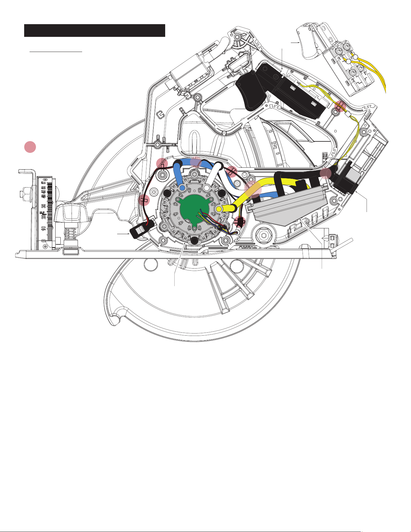
Trigger
Switch
Battery
Terminal Block
PCBA
Board
Motor Stator
LED
Lens
= WIRE TRAPS
or GUIDES
IMPORTANT:
Strong magnetic force. Care must be taken
when installing the Rotor Assembly (87) into the
Stator Assembly. Do not allow rotor bearing or
balancing bushing to hit PCBA on the back end
of the stator. This could cause damage to the
PCBA.
Insert the rotor/stator assembly into pinion
bore of the Upper Guard Gearcase Assembly
(19). Carefully wiggle and push the rotor/stator
until the ball bearing in front of the fan is fully
seated in the bearing bore of the gearcase.
1
2
WIRING DIAGRAM
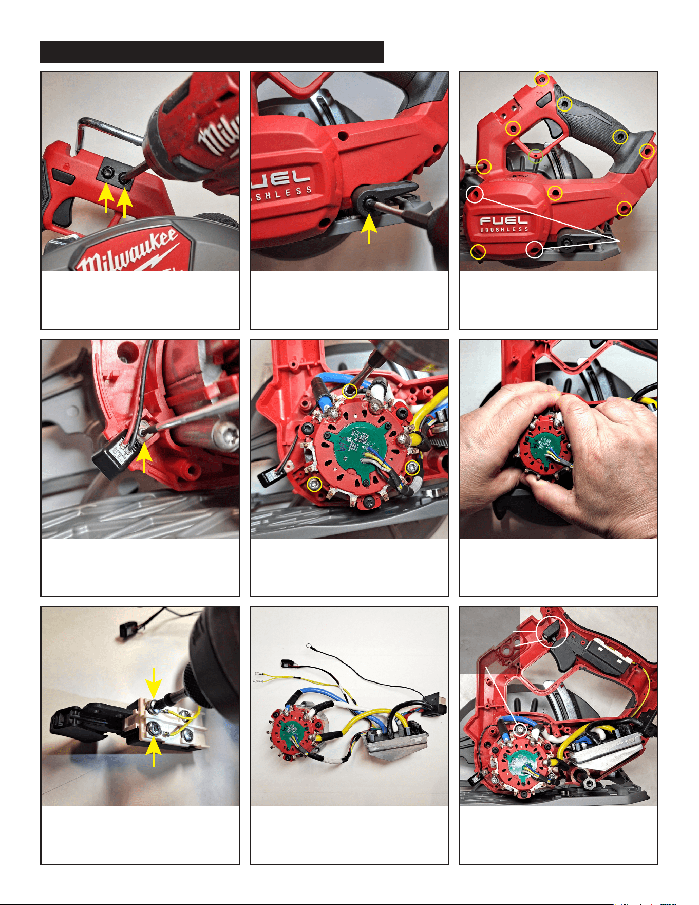
Remove two T-30 screws (fig.51)
from rafter hook assembly.
Remove T-25 screw (fig.69) from
inside plunge lever.
Remove from left housing/handle nine
T-15 screws (fig.63) circled in yellow, two
T-10 screws (fig.67) circled in white and
one T-8 screw (fig.78) circled in green.
Remove T-6 screw (fig.70) from
LED light with screwdriver.
Remove three T-20 screws (fig.47)
from stator.
Firmly grasp the stator with both hands
and forcibly pull the stator from the
magnetic force of the rotor assembly.
Remove 2 top screws from switch
(fig.60) with philips head bit or
screwdriver. Detach yellow wires
from screws/switch.
Remove old PCBA & Stator assembly
and replace with new PCBA & Stator
service assembly 14-46-9964 (fig.85).
Follow directions in reverse order to put
assembly/tool back together. Be sure
there are no interferences and wires are
properly placed within traps/channels.
T-10
(longer)
screws
Don’t forget
to place
switch lock
button,
button flake,
and ground
wire.
HOW TO REPLACE THE ELECTRONICS ASSEMBLY (FIG.85)
2
1
4
5
3
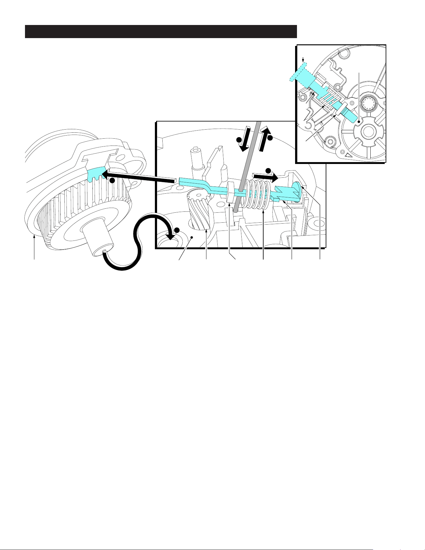
83 19 87 9 10 11 21
11
10
9
21
Locking Cogs
(behind gear)
To prevent damage to the Felt Seal (9) it is recommended to temporarily
remove the felt seal until steps 1 and 2 are completed.
1. With the use of both hands, compress the Spindle Lock Spring (10)
back on the Spindle Lock Plate (11) past the small hole on the plate.
2. While holding the spring back with one hand, quickly insert a thin metal
instrument into the small hole on the plate. The metal instrument
should capture the entire spring (all coils should be behind that tool).
With the spindle lock spring trapped behind the small hole on the
spindle lock plate, slide the felt seal back onto the spindle lock plate.
Position the felt seal above the corresponding cavity in the Upper
Guard Gearcase (19).
3. Insert the open end of the spindle lock plate (11) into the opening of the
Output Gear Assembly (83) behind the gear, as shown.
4. Insert the bearing shaft portion of the output shaft assembly into the
needle bearing of the upper guard gearcase assembly. Carefully
wiggle the entire output shaft assembly until the gearing of the output
shaft assembly engages with the pinion gearing of the Rotor (87) and
the output shaft assembly slides into place.
Secure the output shaft assembly to the upper guard gearcase
assembly with the use of four screws (7), not shown. It is recom-
mended to alternate the tightening of the screws.
5. Remove the thin metal instrument. Check for the proper functioning
of the spindle locking mechanism. Rotate the spindle shaft and depress
the Spindle Lock Button (21) at the same time. The spindle lock plate
should drop into one of four cogs that lock the spindle. Spindle lock
mechanism must return briskly when released from engagement in the
lock block cog.
Detail 'A' shows Spindle Lock Spring (10) and
Felt Seal (9) in place in the respective cavities
of the Upper Guard Gearcase Assembly (19).
NOTE: The spindle hub and gear of the Output
Gear Assembly (83) are not shown for clarity,
so the four Locking Cogs of the Lock Block can
be seen.
A
ASSEMBLING OUTPUT GEAR ASSEMBLY INTO UPPER GUARD GEARCASE