
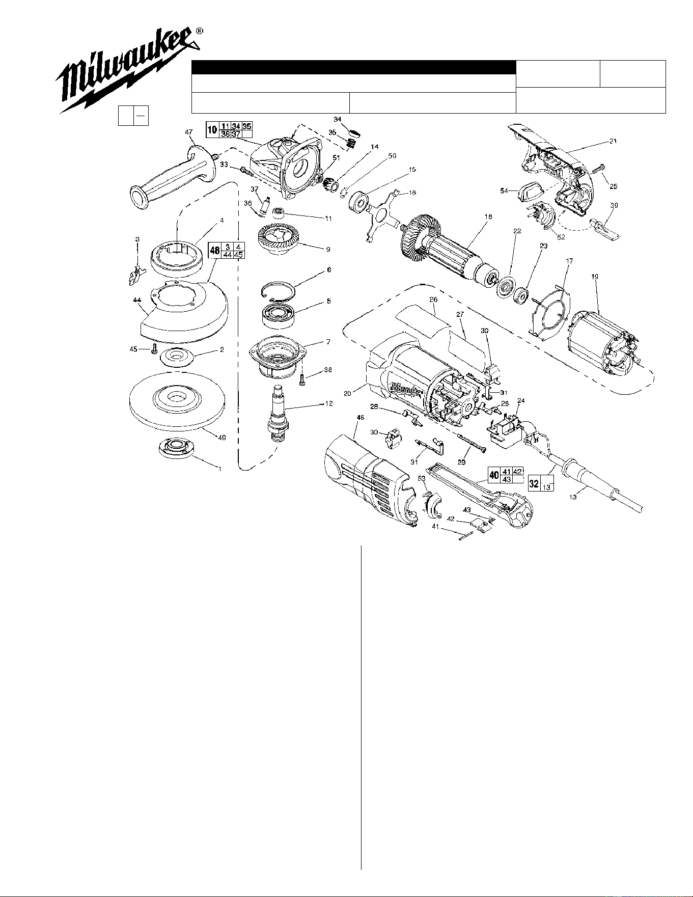
MILWAUKEE ELECTRIC TOOL CORPORATION
13135 W. Lisbon Road, Brookfield, WI 53005
Drwg. 1
FIG. PART NO. DESCRIPTION OF PART NO. REQ.
1 49-05-0051 Flange Nut (1)
2 49-05-0041 Flange (1)
3 44-20-0325 Lock Lever (1)
4 45-36-1551 Spacer (1)
5 02-04-1745 Ball Bearing (1)
6 34-80-2960 Retaining Ring - Internal (1)
7 28-52-0222 Spindle Hub (1)
9 32-05-1310 P.M. Gear (1)
10 25-14-2351 Gear Case Assembly (1)
11 02-50-2423 Needle Bearing (1)
12 38-50-5202 Spindle (1)
13 44-76-0210 Cord Protector (1)
14 32-60-1310 Pinion Gear (1)
15 02-04-0852 Ball Bearing (1)
16 44-66-5345 Bearing Retainer Plate (1)
17 42-14-0400 Baffle (1)
18 16-10-2005 Armature (1)
19 18-10-2005 Field (1)
20 31-50-1100 Motor Housing (1)
21 31-44-0660 Right Cover (1)
22 23-16-0100 Commutator Insulator (1)
23 02-04-2080 Ball Bearing (1)
24 23-66-2401 Switch (1)
25 06-82-7271 6-19 x 7/8" Pan Hd. Plastite T-15 (4)
26 12-20-6201 Service Nameplate Kit (1)
27 10-98-7091 Warning Label (1)
28 23-74-1206 Brush Terminal (2)
29 06-82-7421 6-19 x 3-1/4" Pan Hd. Slt. Plast. T-15 (2)
30 22-20-0920 Brush Holder Assy. (Incl. Carbon Brush) (2)
31 23-74-1201 Switch Terminal (2)
32 22-64-0845 Cord Set Assembly (1)
33 06-82-7326 8-16 x 1" Pan Hd. Slt. Plast. T-20 (4)
34 31-12-0205 Cap (1)
35 40-50-8650 Compression Spring (1)
36 34-40-4300 O-Ring (1)
37 44-60-0845 Lock Pin (1)
38 06-82-5316 8-32 x 1/2" Pan Hd. Slt. Tapt. T-20 (4)
39 31-53-0080 Plug (1)
FIG. PART NO. DESCRIPTION OF PART NO. REQ.
40 31-92-0320 Paddle Assembly (1)
41 06-65-1915 Pin (1)
42 42-42-0390 Lock-Off Button (1)
43 40-50-8750 Torsion Spring (1)
44 28-41-1020 Hood (1)
45 06-82-7251 8-16 x 3/8" Pan Hd. Slt. Plast. T-20 (3)
46 31-44-0665 Left Cover (1)
47 49-15-0310 Side Handle (1)
48 49-12-0365 Guard Assembly (1)
49 --------------- 4-1/2" Disc - Select From Catalog (1)
50 45-14-0280 Pinion Shim (1)
51 06-55-3850 10-32 Hex Nut (1)
52 31-17-0260 Cord Clamp Half-Right (1)
53 31-17-0265 Cord Clamp Half-Left (1)
54 31-53-0150 Plug (1)
49-96-7205 Spanner Wrench (1)
FIG. LUBRICATION:
9,14 Type "Y" Grease, No. 49-08-5270, Must Be Applied
To All Gear Teeth.
10 9-12 Grams Type "Y" Grease, No. 49-08-5270.
FIG. NOTES:
7 Position The Spindle Hub With The Side That Has The
Word "Back" Orientated Toward The Rear Of The Tool.
11 Press .09" Below Casting Surface With Lettering Readable
After Assembly.
32 Tuck All Cord Leads Away From Vent Openings. Cord
Leads
Are Interchangeable On Switch Connections.
51 Torque To 25-35 In./Lbs.
6153-20
54-38-3701
906B
4-1/2" SUPER MAG GRINDER
EXAMPLE:
Component Parts (Small #)
Are Included When Ordering
The Assembly (Large #).
REVISED BULLETIN DATE
Nov. 2000
SERVICE PARTS LIST
BULLETIN NO.
WIRING INSTRUCTION
CATALOG NO.
SPECIFY CATALOG NO. AND SERIAL NO. WHEN ORDERING PARTS
STARTING
SERIAL NUMBER
0
00
54-38-3700
«
«
«