10-INCH BENCHTOP
TABLE SAW
Instruction Manual
MODEL TT1015
IMPORTANT: Your new tool has been engineered and manufactured to WEN’s highest standards for dependability,
ease of operation, and operator safety. When properly cared for, this product will supply you years of rugged,
trouble-free performance. Pay close attention to the rules for safe operation, warnings, and cautions. If you use
your tool properly and for its intended purpose, you will enjoy years of safe, reliable service.
NEED HELP? CONTACT US!
Have product questions? Need technical support? Please feel free to contact us:
TECHSUPPOR[email protected]
1-800-232-1195 (M-F 8AM-5PM CST)
For replacement parts and the most up-to-date instruction manuals, visit WENPRODUCTS.COM

2
CONTENTS
WELCOME 3
Introduction ..................................................................................................... 3
Specifications ................................................................................................... 3
SAFETY 4
General Safety Rules ........................................................................................ 4
Specific Rules for Your Table Saw .................................................................... 6
Electrical Information ..................................................................................... 10
BEFORE OPERATING 11
Unpacking & Packing List .............................................................................. 11
Know Your Table Saw .................................................................................... 12
Assembly ....................................................................................................... 13
16
Operation ....................................................................................................... 16
Adjustments ................................................................................................... 25
Maintenance .................................................................................................. 30
Troubleshooting Guide ................................................................................... 32
Exploded View & Parts List ............................................................................ 33
Warranty Statement ....................................................................................... 37
OPERATION & MAINTENANCE
To purchase accessories for your tool, visit WENPRODUCTS.COM
10-Inch Benchtop Table Saw Rolling Stand (Model TT1088)
8-inch Dado Blade Set (Model BL088D)
Zero Clearance Dado Insert (Model TT1015-DADO)
10-Inch Saw Blades (Models BL1012, BL1024, BL1024C, BL1028, BL1032-2, BL1040, BL1040C, BL1060,
BL1060C, BL1080, BL1080C)

INTRODUCTION
Thanks for purchasing the WEN Table Saw. We know you are excited to put your tool to work, but first, please
take a moment to read through the manual. Safe operation of this tool requires that you read and understand this
operator’s manual and all the labels affixed to the tool. This manual provides information regarding potential safety
concerns, as well as helpful assembly and operating instructions for your tool.
NOTE: The following safety information is not meant to cover all possible conditions and situations that may occur.
WEN reserves the right to change this product and specifications at any time without prior notice.
At WEN, we are continuously improving our products. If you find that your tool does not exactly match this manual,
please visit wenproducts.com for the most up-to-date manual or contact our customer service at 1-800-232-1195.
Keep this manual available to all users during the entire life of the tool and review it frequently to maximize
safety for both yourself and others.
SAFETY ALERT SYMBOL: Indicates danger, warning, or caution. The safety symbols and the explanations
with them deserve your careful attention and understanding. Always follow the safety precautions to reduce the
risk of fire, electric shock or personal injury. However, please note that these instructions and warnings are not
substitutes for proper accident prevention measures.
SPECIFICATIONS
3
Model Number TT1015
Motor 120V, 60Hz, 15A
No-Load Speed 4,800 RPM
Blade Dimensions 10" Diameter, 5/8" Arbor, 40T, 1.6mm Thick, 2.5mm Kerf
Blade Part Number BL1040
Max Depth of Cut
At 90º - 3-1/8"
At 45º - 2-1/4"
Max. Rip Right of Blade 28"
Dado Blades Up to 8" Diameter, Up to 13/16" Width
Dust Port Diameter 2-1/2"
Fence 1" W x 2.36" H
Auxiliary Fence 1.10" W x 0.47" H (28mm x 12 mm)
Table Dimensions 26-1/4" x 22"
Product Weight 61.3 Pounds
Product Dimensions 36.14" x 43.75" x 20.28"

GENERAL SAFETY RULES
4
WORK AREA SAFETY
1. Keep work area clean and well lit. Cluttered or dark
areas invite accidents.
2. Do not operate power tools in explosive atmo-
spheres, such as in the presence of flammable liquids,
gases or dust. Power tools create sparks which may ig-
nite the dust or fumes.
3. Keep children and bystanders away while operat-
ing a power tool. Distractions can cause you to lose
control.
ELECTRICAL SAFETY
1. Power tool plugs must match the outlet. Never mod-
ify the plug in any way. Do not use any adapter plugs
with earthed (grounded) power tools. Unmodified plugs
and matching outlets will reduce risk of electric shock.
2. Avoid body contact with earthed or grounded sur-
faces such as pipes, radiators, ranges and refrigera-
tors. There is an increased risk of electric shock if your
body is earthed or grounded.
3. Do not expose power tools to rain or wet condi-
tions. Water entering a power tool will increase the risk
of electric shock.
4. Do not abuse the cord. Never use the cord for car-
rying, pulling or unplugging the power tool. Keep cord
away from heat, oil, sharp edges or moving parts. Dam-
aged or entangled cords increase the risk of electric
shock.
5. When operating a power tool outdoors, use an ex-
tension cord suitable for outdoor use. Use of a cord
suitable for outdoor use reduces the risk of electric
shock.
6. If operating a power tool in a damp location is
unavoidable, use a ground fault circuit interrupter
(GFCI) protected supply. Use of a GFCI reduces the risk
of electric shock.
PERSONAL SAFETY
1. Stay alert, watch what you are doing and use com-
mon sense when operating a power tool. Do not use
a power tool while you are tired or under the influence
of drugs, alcohol or medication. A moment of inatten-
tion while operating power tools may result in serious
personal injury.
2. Use personal protective equipment. Always wear
eye protection. Protective equipment such as a respira-
tory mask, non-skid safety shoes and hearing protec-
tion used for appropriate conditions will reduce the risk
of personal injury.
3. Prevent unintentional starting. Ensure the switch is
in the off-position before connecting to power source
and/or battery pack, picking up or carrying the tool.
Carrying power tools with your finger on the switch or
energizing power tools that have the switch on invites
accidents.
4. Remove any adjusting key or wrench before turning
the power tool on. A wrench or a key left attached to a
rotating part of the tool may result in personal injury.
5. Do not overreach. Keep proper footing and balance
at all times. This enables better control of the power tool
in unexpected situations.
6. Dress properly. Do not wear loose clothing or jew-
elry. Keep your hair and clothing away from moving
parts. Loose clothes, jewelry or long hair can be caught
in moving parts.
7. If devices are provided for the connection of dust
extraction and collection facilities, ensure these are
connected and properly used. Use of dust collection
can reduce dust-related hazards.
8. Do not let familiarity gained from frequent use of
tools allow you to become complacent and ignore tool
safety principles. A careless action can cause severe
injury within a fraction of a second.
Safety is a combination of common sense, staying alert and knowing how your item works. The term “power tool”
in the warnings refers to your mains-operated (corded) power tool or battery-operated (cordless) power tool.
SAVE THESE SAFETY INSTRUCTIONS.
WARNING! Read all safety warnings and all instructions. Failure to follow the warnings and instructions
may result in electric shock, fire and/or serious injury.

GENERAL SAFETY RULES
5
POWER TOOL USE AND CARE
1. Do not force the power tool. Use the correct power
tool for your application. The correct power tool will do
the job better and safer at the rate for which it was de-
signed.
2. Do not use the power tool if the switch does not turn
it on and off. Any power tool that cannot be controlled
with the switch is dangerous and must be repaired.
3. Disconnect the plug from the power source and/or
the battery pack from the power tool before making
any adjustments, changing accessories, or storing
power tools. Such preventive safety measures reduce
the risk of starting the power tool accidentally.
4. Store idle power tools out of the reach of children
and do not allow persons unfamiliar with the power
tool or these instructions to operate the power tool.
Power tools are dangerous in the hands of untrained
users.
5. Maintain power tools. Check for misalignment or
binding of moving parts, breakage of parts and any oth-
er condition that may affect the power tool’s operation.
If damaged, have the power tool repaired before use.
Many accidents are caused by poorly maintained power
tools.
6. Keep cutting tools sharp and clean. Properly main-
tained cutting tools with sharp cutting edges are less
likely to bind and are easier to control.
7. Use the power tool, accessories and tool bits, etc.
in accordance with these instructions, taking into ac-
count the working conditions and the work to be per-
formed. Use of power tool for operations different from
those intended could result in a hazardous situation.
8. Use clamps to secure your workpiece to a stable
surface. Holding a workpiece by hand or using your
body to support it may lead to loss of control.
9. KEEP GUARDS IN PLACE and in working order.
10. Keep handles and grasping surfaces dry, clean
and free from oil and grease. Slippery handles and
grasping surfaces do not allow for safe handling and
control of the tool in unexpected situations.
SERVICE
1. Have your power tool serviced by a qualified repair
person using only identical replacement parts. This
will ensure that safety of the power tool is maintained.
CALIFORNIA PROPOSITION 65 WARNING
Some dust created by power sanding, sawing, grinding,
drilling, and other construction activities may contain
chemicals, including lead, known to the State of Califor-
nia to cause cancer, birth defects, or other reproductive
harm. Wash hands after handling. Some examples of
these chemicals are:
• Lead from lead-based paints.
• Crystalline silica from bricks, cement, and other ma-
sonry products.
• Arsenic and chromium from chemically treated lum-
ber.
Your risk from these exposures varies depending on
how often you do this type of work. To reduce your ex-
posure to these chemicals, work in a well-ventilated area
with approved safety equipment such as dust masks
specially designed to filter out microscopic particles.
Safety is a combination of common sense, staying alert and knowing how your item works. The term “power tool”
in the warnings refers to your mains-operated (corded) power tool or battery-operated (cordless) power tool.
SAVE THESE SAFETY INSTRUCTIONS.
WARNING! Read all safety warnings and all instructions. Failure to follow the warnings and instructions
may result in electric shock, fire and/or serious injury.

TABLE SAW SAFETY
1. Never place your hands in the vicinity of, or in line
with, the saw blade.
2. Always wear ANSI Z87.1 approved eye protection, as
well as hearing protection and respiratory protection.
3. Avoid kickback. Keep the blade sharp and the rip
fence parallel to the saw blade. Make sure the riving
knife, anti-kickback devices, and the blade guard are in
place, properly aligned, and functional. Do not release
a workpiece before passing it completely through the
blade. Do not rip a workpiece that is twisted or warped.
Do not attempt to pull the workpiece backwards out of a
cut while the blade is still turning.
4. Always use a properly functioning saw blade guard,
riving knife and anti-kickback device for every operation
for which it can be used, including all through sawing.
5. Use a push-stick or push-block when required, espe-
cially when ripping narrow workpieces. A push stick is
supplied with the saw.
6. Do not perform any operation freehand. Always use
the fence, miter gauge, or both to support and guide the
workpiece.
7. Pay particular attention to instructions on reducing
the risk of kickback.
8. Never reach around or over the saw blade.
9. Turn off tool and wait for the saw blade to come to
a complete stop before moving workpiece or changing
settings.
10. Never stand directly in line with the saw blade. Al-
ways position your body on the same side of the saw
blade as the fence.
11. Support large panels to minimize the risk of blade
pinching or kickback.
12. Keep hands out of the line of the saw blade.
13. DON'T USE IN DANGEROUS ENVIRONMENT. Don't
use power tools in damp or wet locations, or expose
them to rain. Keep work area well lit. Do not use power
tools in the presence of flammable liquids or gases.
14. MAKE WORKSHOP KID PROOF with padlocks, mas-
ter switches, or by removing starter keys.
15. USE THE RIGHT TOOL. Don't force tool or attach-
ment to do a job for which it was not designed.
16. WEAR PROPER APPAREL. Do not wear loose cloth-
ing, gloves, neckties, rings, bracelets, or other jewelry
which may get caught in moving parts. Nonslip foot-
wear is recommended. Tie back long hair.
17. CHECK DAMAGED PARTS. Before further use of the
tool, a guard or other part that is damaged should be
carefully checked to determine that it will operate prop-
erly and perform its intended function - check for align-
ment of moving parts, binding of moving parts, break-
age of parts, mounting, and any other conditions that
may affect its operation. A guard or other part that is
damaged should be properly repaired or replaced.
18. REMOVE ALL ACCESSORIES from the table prior to
transporting the saw.
19. DANGER - NEVER attempt to free a stalled blade
without first turning the saw OFF and unplugging it.
20. PROVIDE ADEQUATE SUPPORT to long or wide
workpieces.
21. AVOID AWKWARD OPERATIONS and hand posi-
tions, where a sudden slip could cause your hand to
move into the blade or its path.
22. SECURELY MOUNT THE TABLE SAW to a workbench
or stand before performing any cutting operations.
23. NEVER CUT METALS or any material that creates
hazardous dust.
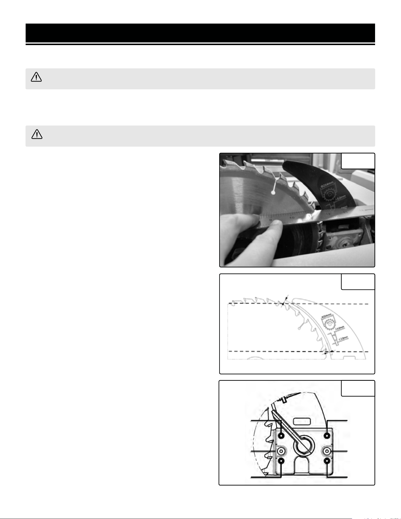
SAW BLADE SAFETY
1. Always wear protective gloves when handling saw
blades.
2. Only use blades with correct size and type for both
your table saw and your workpiece.
• The rated diameter of the saw blade is 10 inches
with a 5/8 inch arbor.
• The no-load speed of the table saw is 4800 RPM.
The maximum permissible speed of your saw blade
should always be higher than the no-load rotational
speed of the saw.
SPECIFIC RULES FOR YOUR TABLE SAW
WARNING! Do not operate the power tool until you have read and understood the following instructions
and the warning labels.
6

3. Never use damaged or deformed saw blades. Only
use sharp blades.
4. Install the saw blade in the correct orientation indi-
cated in the instructions.
5. Keep hands out of path of saw blade. Never use your
hands to remove sawdust, chips or workpiece near the
saw blade or the cutting path of the saw.
6. Never reach around the blade or in back of the blade.
7. Do not use blades made from high-speed steel, abra-
sive blades, metal-cutting blades or masonry-cutting
blades. The guards of this saw are not designed to pro-
tect against the failure of such blades.
8. The use of accessories or attachments not recom-
mended by the manufacturer may result in a risk of per-
sonal injury.
GUARD-RELATED WARNINGS
1. Keep guards in place. Guards must be in working
order and be properly mounted. A guard that is loose,
damaged, or is not functioning correctly must be re-
paired or replaced.
2. Always use saw blade guard, riving knife and anti-
kickback device for every through-cutting operation. For
through-cutting operations where the saw blade cuts
completely through the thickness of the workpiece, the
guard and other safety devices help reduce the risk of
injury.
3. Immediately reattach the guarding system after com-
pleting an operation (such as rabbeting, dadoing or re-
sawing cuts) which requires removal of the guard, riv-
ing knife and/or anti-kickback device. The guard, riving
knife, and anti-kickback device help to reduce the risk
of injury.
4. Make sure the saw blade is not contacting the guard,
riving knife or the workpiece before the switch is turned
on. Inadvertent contact of these items with the saw
blade could cause a hazardous condition.
5. Adjust the riving knife as described in this instruc-
tion manual. Incorrect spacing, positioning and align-
ment can make the riving knife ineffective in reducing
the likelihood of kickback.
6. For the riving knife and anti-kickback device to work,
they must be engaged in the workpiece. The riving knife
and anti-kickback device are ineffective when cutting
workpieces that are too short to be engaged with the
riving knife and anti-kickback device. Under these con-
ditions a kickback cannot be prevented by the riving
knife and anti-kickback device.
7. Use the appropriate saw blade for the riving knife.
For the riving knife to function properly, the saw blade
diameter must match the appropriate riving knife and
the body of the saw blade must be thinner than the
thickness of the riving knife and the cutting width of
the saw blade must be wider than the thickness of the
riving knife.
CUTTING PROCEDURES WARNINGS
1. DANGER: Never place your fingers or hands in the
vicinity of or in line with the saw blade. A moment of
inattention or a slip could direct your hand towards the
saw blade and result in serious personal injury.
2. Feed the workpiece into the saw blade or cutter only
against the direction of rotation. Feeding the workpiece
in the same direction that the saw blade is rotating
above the table may result in the workpiece, and your
hand, being pulled into the saw blade.
3. Never use the miter gauge to feed the workpiece
when ripping and do not use the rip fence as a length
stop when cross cutting with the miter gauge. Guiding
the workpiece with the rip fence and the miter gauge
at the same time increases the likelihood of saw blade
binding and kickback.
4. When ripping, always apply force to the workpiece
between the fence and the saw blade. Use a push stick
when the distance between the fence and the saw blade
is less than 6 inches (150mm), and use a push block
when this distance is less than 2 inches (50mm). Work
helping devices will keep your hand at a safe distance
from the saw blade.
5. Use only the push stick provided by the manufacturer
or constructed in accordance with the instructions. This
push stick provides sufficient separation between the
hand and the saw blade.
SPECIFIC RULES FOR YOUR TABLE SAW
7
WARNING! Do not operate the power tool until you have read and understood the following instructions
and the warning labels.

8
SPECIFIC RULES FOR YOUR TABLE SAW
WARNING! Do not operate the power tool until you have read and understood the following instructions
and the warning labels.
6. Never use a damaged or cut push stick. It may break
causing your hand to slip into the saw blade.
7. Do not perform any operation freehand. Always use
either the rip fence or the miter gauge to position and
guide the workpiece. Freehand means using your hands
to support or guide the workpiece, in lieu of a rip fence
or miter gauge. Freehand sawing leads to misalignment,
binding and kickback.
8. Never reach around or over a rotating saw blade. This
may lead to accidental contact with moving saw blade.
9. Provide auxiliary workpiece support to the rear and/
or sides of the saw table for long and/or wide work-
pieces to keep them level. A long and/or wide workpiece
has a tendency to pivot on the table’s edge, causing loss
of control, saw blade binding and kickback.
10. Feed workpiece at an even pace. Do not bend or
twist the workpiece. If jamming occurs, turn the tool off
immediately, unplug the tool then clear the jam. Jam-
ming the saw blade by the workpiece can cause kick-
back or stall the motor.
11. Do not remove pieces of cut-off material while the
saw is running. The material may become trapped be-
tween the fence or inside the saw blade guard and the
saw blade, pulling your fingers into the saw blade. Turn
the saw off and wait until the saw blade stops before
removing material.
12. Use an auxiliary fence in contact with table top when
ripping workpieces less than 2mm thick. A thin work-
piece may wedge under rip fence and create kickback.
KICKBACK CAUSES AND RELATED WARNINGS
Kickback is a sudden reaction of the workpiece due to a
pinched, jammed saw blade or misaligned line of cut in
the workpiece with respect to the saw blade or when a
part of the workpiece binds between the saw blade and
the rip fence or other fixed object. Most frequently dur-
ing kickback, the workpiece is lifted from the table by the
rear portion of the saw blade and is propelled towards
the operator. Kickback is the result of saw misuse and/
or incorrect operating procedures or conditions and can
be avoided by taking proper precautions as given.
1. Never stand directly in line with the saw blade. Al-
ways position your body on the same side of the saw
blade as the fence. Kickback may propel the workpiece
at high velocity towards anyone standing in front and in
line with the saw blade.
2. Never reach over or in back of the saw blade to pull
or to support the workpiece. Accidental contact with the
saw blade may occur or kickback may drag your fingers
into the saw blade.
3. Never hold and press the workpiece that is being cut
off against the rotating saw blade. Pressing the work-
piece being cut off against the saw blade will create a
binding condition and kickback.
4. Align the fence to be parallel with the saw blade. A
misaligned fence will pinch the workpiece against the
saw blade and create kickback.
5. Use a featherboard to guide the workpiece against the
table and fence when making non-through cuts such as
rabbeting, dadoing or resawing cuts. A featherboard
helps to control the workpiece in the event of a kickback.
6. Use extra caution when making a cut into blind ar-
eas of assembled workpieces. The protruding saw blade
may cut objects that can cause kickback.
7. Support large panels to minimize the risk of saw blade
pinching and kickback. Large panels tend to sag under
their own weight. Support(s) must be placed under all
portions of the panel overhanging the table top.
8. Use extra caution when cutting a workpiece that is
twisted, knotted, warped or does not have a straight
edge to guide it with a miter gauge or along the fence.
A warped, knotted, or twisted workpiece is unstable and
causes misalignment of the kerf with the saw blade,
binding and kickback.
9. Never cut more than one workpiece, stacked verti-
cally or horizontally. The saw blade could pick up one or
more pieces and cause kickback.

9
SPECIFIC RULES FOR YOUR TABLE SAW
WARNING! Do not operate the power tool until you have read and understood the following instructions
and the warning labels.
10. When restarting the saw with the saw blade in the
workpiece, center the saw blade in the kerf so that the
saw teeth are not engaged in the material. If the saw
blade binds, it may lift up the workpiece and cause kick-
back when the saw is restarted.
11. Keep saw blades clean, sharp, and with sufficient
set. Never use warped saw blades or saw blades with
cracked or broken teeth. Sharp and properly set saw
blades minimize binding, stalling and kickback.
TABLE SAW OPERATION WARNINGS
1. Turn off the table saw and disconnect the power cord
when removing the table insert, changing the saw blade
or making adjustments to the riving knife, ant kickback
device or saw blade guard, and when the machine is
left unattended. Precautionary measures will avoid ac-
cidents.
2. Never leave the table saw running unattended. Turn it
off and don’t leave the tool until it comes to a complete
stop. An unattended running saw is an uncontrolled
hazard.
3. Locate the table saw in a well-lit and level area where
you can maintain good footing and balance. It should be
installed in an area that provides enough room to easily
handle the size of your workpiece. Cramped, dark areas,
and uneven or slippery floors invite accidents.
4. Frequently clean and remove sawdust from under the
saw table and/or the dust collection device. Accumu-
lated sawdust is combustible and may self-ignite.
5. The table saw must be secured. A table saw that is
not properly secured may move or tip over. Mount it
securely to a benchtop or stand before cutting.
6. Remove tools, wood scraps, etc. from the table be-
fore the table saw is turned on. Distraction or a potential
jam can be dangerous.
7. Always use saw blades with correct size and shape
(diamond versus round) of arbor holes. Saw blades that
do not match the mounting hardware of the saw will run
off-center, causing loss of control.
8. Never use damaged or incorrect saw blade mount-
ing means such as flanges, saw blade washers, bolts or
nuts. These mounting means were specially designed
for your saw, for safe operation and optimum perfor-
mance.
9. Never stand on the table saw, do not use it as a step-
ping stool. Serious injury could occur if the tool is tipped
or if the cutting tool is accidentally contacted.
10. Make sure that the saw blade is installed to rotate in
the proper direction. Do not use grinding wheels, wire
brushes, or abrasive wheels on a table saw. Improper
saw blade installation or use of accessories not recom-
mended may cause serious injury.
CAUTION: This means that if precautions are not heed-
ed, it may result in minor or moderate injury and/or
possible machine damage.
WARNING: This means that if precautions are not
heeded, it could result in serious injury or possibly even
death.
WARNING: The operation of any power tool can result
in foreign objects being thrown into your eyes, which
can result in severe eye damage. Before beginning pow-
er tool operation, always wear safety goggles or safety
glasses with side shields and a full face shield when
needed. Always use eye protection which is marked to
comply with ANSI Z87.1.
WARNING: If the power cord requires replacement, this
must be done by the manufacturer.
WARNING: Only cut wood on this table saw. Do not cut
any plastic and metal on this saw.
WARNING: Always keep guards in place and in proper
operating condition.
WARNING: Use blade guard for every applicable opera-
tion including all through cuts. If the guard is removed
for special non-through cuts, such as dado or rabbet
cuts, replace the blade guard before further use of the
saw.
WARNING: Keep hands out of the line of the saw blade.
Never reach around or over the saw blade.
10
AMPERAGE
REQUIRED GAUGE FOR EXTENSION CORDS
25 ft. 50 ft. 100 ft. 150 ft.
15A 14 gauge 12 gauge Not Recommended Not Recommended
ELECTRICAL INFORMATION
1. EXAMINE EXTENSION CORD BEFORE USE. Make sure your extension cord is properly wired and in good con-
dition. Always replace a damaged extension cord or have it repaired by a qualified person before using it.
2. DO NOT ABUSE EXTENSION CORD. Do not pull on cord to disconnect from receptacle; always disconnect by
pulling on plug. Disconnect the extension cord from the receptacle before disconnecting the product from the
extension cord. Protect your extension cords from sharp objects, excessive heat and damp/wet areas.
3. USE A SEPARATE ELECTRICAL CIRCUIT FOR YOUR TOOL. This circuit must not be less than a 12-gauge wire
and should be protected with a 15A time-delayed fuse. Before connecting the motor to the power line, make sure
the switch is in the OFF position and the electric current is rated the same as the current stamped on the motor
nameplate. Running at a lower voltage will damage the motor.
When using an extension cord, be sure to use one heavy enough to carry the current your product will draw.
An undersized cord will cause a drop in line voltage resulting in loss of power and overheating. The table below
shows the correct size to be used according to cord length and ampere rating. When in doubt, use a heavier
cord. The smaller the gauge number, the heavier the cord.
GUIDELINES AND RECOMMENDATIONS FOR EXTENSION CORDS
IMPORTANT: Servicing a double-insulated product requires extreme care and knowledge of the system, and
should be done only by qualified service personnel using identical replacement parts. Always use original factory
replacement parts when servicing.
1. POLARIZED PLUGS. To reduce the risk of electric shock, this equipment has a polarized plug (one blade is wider
than the other). This plug will fit in a polarized outlet only one way. If the plug does not fit fully in the outlet, reverse
the plug. If it still does not fit, contact a qualified electrician to install a proper outlet. Do not modify the machine
plug or the extension cord in any way.
2. GROUND FAULT CIRCUIT INTERRUPTER PROTECTION (GFCI) should be provided on the circuit or outlet used
for this power tool to reduce the risk of electric shock.
3. SERVICE AND REPAIR. To avoid danger, electrical appliances must only be repaired by qualified service techni-
cian using original replacement parts.
DOUBLE-INSULATED TOOLS
The tool’s electrical system is double insulated where two systems of insulation are provided. This
eliminates the need for the usual three-wire grounded power cord. Double insulated tools do not
need to be grounded, nor should a means for grounding be added to the product. All exposed metal
parts are isolated from the internal metal motor components with protecting insulation.
11
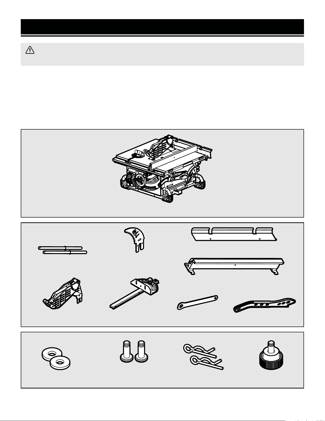
UNPACKING
With the help of a friend or trustworthy foe, carefully remove the table saw from the packaging. Make sure to take
out all contents and accessories. Do not discard the packaging until everything is removed. Check the packing list
below to make sure you have all of the parts and accessories. If any part is missing or broken, please contact our
customer service at 1-800-232-1195 (M-F 8-5 CST), or email [email protected].
PACKING LIST
Components
UNPACKING & PACKING LIST
WARNING! Do not plug in or turn on the tool until it is fully assembled according to the instructions. Failure
to follow the safety instructions may result in serious personal injury.
Accessories & Tools
Table Saw (1)
Riving Knife (1)
(Pre-Installed)
Miter Gauge (1)
Push Stick (1)Arbor Wrench (1)
Table Extension Rest (1)
Rip Fence (1)
(Stored on side of saw)
Blade Guard (1)
Table Extension Shafts (2)
Hardware Bag (1)
Fence Lock Knob (1)
R Clips (2)6mm Flat Washers (2)
M6x10 Phillips-Head
Screw (2)
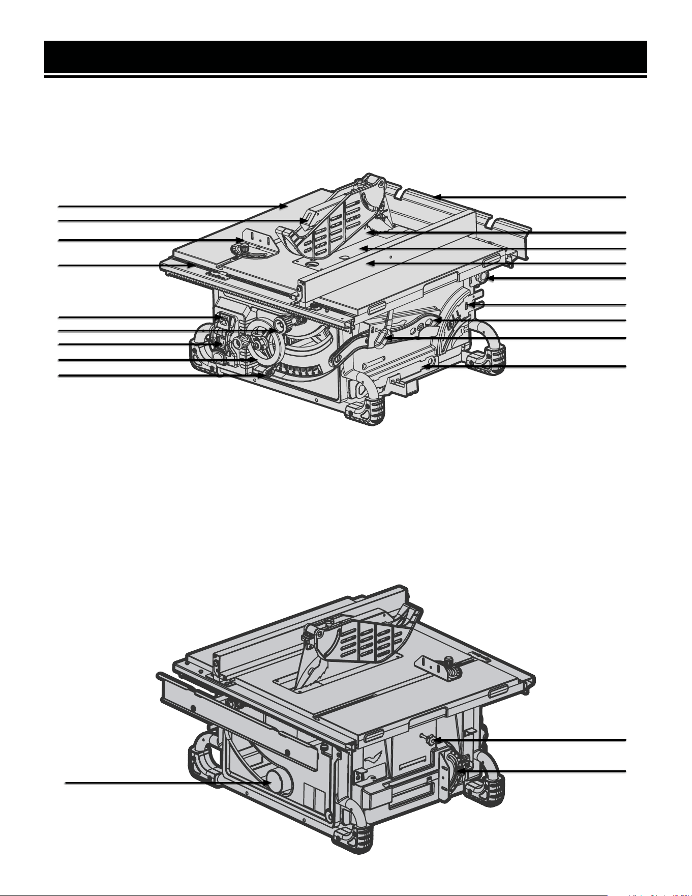
KNOW YOUR TABLE SAW
12
TOOL PURPOSE
Make smooth, straight cuts easily with your WEN Table Saw. Refer to the following diagrams to become familiar-
ized with all the parts and controls of your table saw. The components will be referred to later in the manual for
assembly and operation instructions.
1
3
1. Worktable
2. Blade Guard
3. Miter Gauge
4. Fence Scale
5. Switch Lock-out Cover
6. Fence Adjustment Knob
7. Power Switch
15. Riving Knife & Storage
16. Push Stick
17. Fence Lock Lever
18. Tool Storage
19. Dust Port
20. Fence Storage
21. Miter Gauge Storage
8. Height Adjustment Wheel
9. Bevel Locking Lever
10. Rear Extension
11. Saw Blade
12. Table Insert
13. Rip Fence
14. Blade Guard Storage
4
6
7
8
9
11
12
2
10
13
14
15
16
17
18
5
19
21
20
13
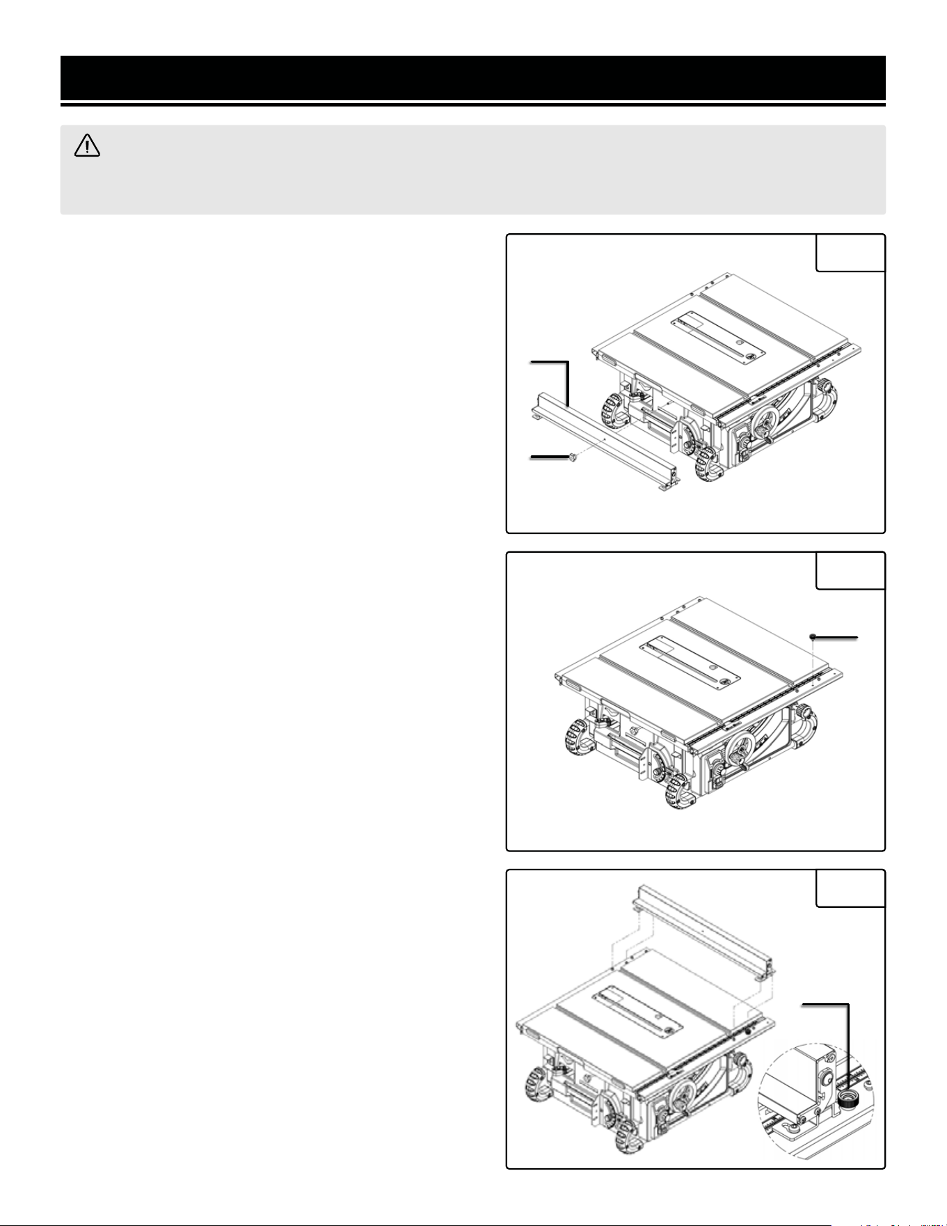
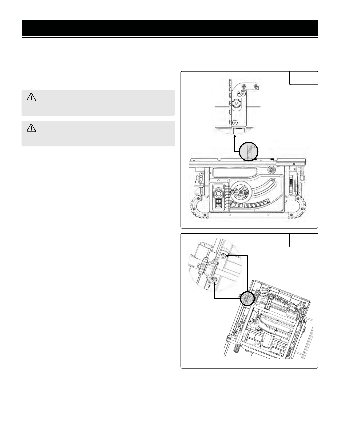
INSTALLING THE FENCE
NOTE: The fence is shipped in its storage position on the
left side of the saw.
1. Loosen the lock knob (Fig. 2 - 1), then remove the fence
assembly (Fig. 2 - 2).
2. Install the fence locking knob (Fig. 3 - 1) (found in the
hardware bag) on the front rail.
3. Place the fence on the rails, with the mounting holes po-
sitioned over the (3) pre-installed mounting screws. Then
tighten the fence locking knob (Fig. 4 - 1) to secure the
fence.
NOTE: The fence can be installed in 1 of 2 positions. The
inner position (closer to the blade) can be used for rip cuts
up to 24" wide. The outer position can be used for rip cuts
up to 28" wide.
ASSEMBLY
WARNING! Do not plug in or turn on the tool until it is fully assembled according to the instructions. Read
through and become familiarized with the following procedures of handling and adjusting your tool. Failure to
follow the safety instructions may result in serious personal injury.
Fig. 2
Fig. 3
1
1
Fig. 4
2
1
INSTALLING THE TABLE EXTENSION
1. Use a Phillips-head screwdriver (not included) to attach
the table extension rods (Fig. 5 - 1) to the table extension
(Fig. 5 - 2) with the M6x10 screws and 6mm washers.
2. Loosen both knobs (Fig. 6 - 1) on the rear side of the
saw and insert the extension rods into the holes. Once the
table extension is in the desired position, tighten the knobs.
To reposition the extension, loosen the knobs, adjust the
extension to the desired position, and tighten the knobs.
3. Insert the R-clips (Fig. 7 - 1) into the holes in the two
rear extension rods to secure the table extension.
ASSEMBLY
1
Fig. 6
1
Fig. 7
Fig. 5
1
2
1
14
15
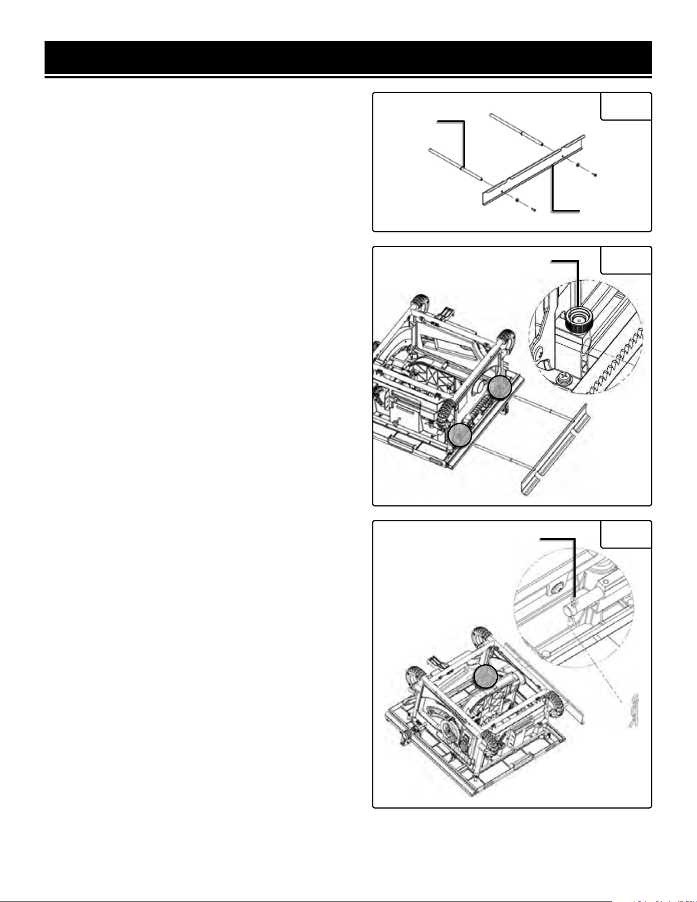
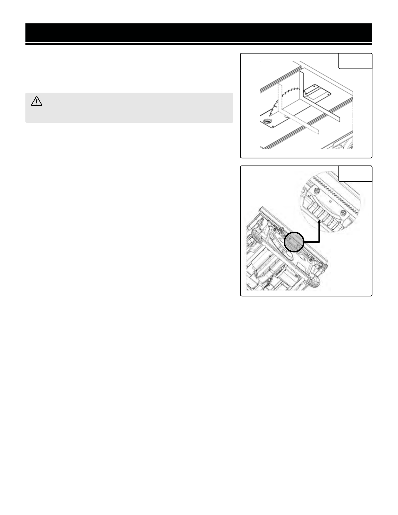
INSTALLING THE BLADE GUARD
ASSEMBLY
WARNING! Disconnect the machine from the power
source before performing the following steps.
1. Remove the table insert (Fig. 8 - 1) by turning the lock
knob (Fig. 8 - 2) 1/4 turn. Lift the insert out of the table
(Fig. 9 - 1).
2. Loosen the height adjustment lock knob (Fig. 9 - 3; in the
center of the height adjustment handwheel, Fig. 9 - 2). Turn
the height adjustment wheel (Fig. 9 - 2) clockwise to raise
the saw blade to its maximum height.
3. Move the lock lever (Fig. 10 - 1) up to release the riving
knife. Remove the riving knife.
4. Insert the blade guard assembly into the clamp. Ensure
the holes in the spreader align with the bumps inside the
clamp. Secure the assembly by pressing the lock lever
down. Test the clamp by gently pulling up on the assembly.
It should stay secured (Fig. 12).
5. To reinstall the riving knife, follow steps 2 and 3 to re-
move the blade guard assembly. When reinstalling, make
sure the riving knife is between 1/8" - 5/16" (3mm - 8mm)
from the saw blade (Fig. 11).
Fig. 8
Fig. 9
1
1
Fig. 10
Fig. 11 Fig. 12
2
2
1
3mm - 8mm
Blade Guard Cover Anti-Kickback Pawl
Riving Knife
(Spreader)
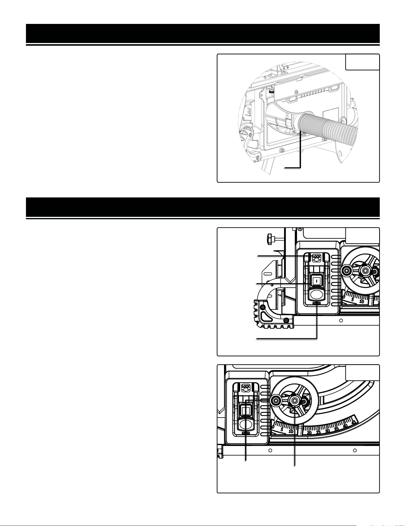
DUST COLLECTION
1. Attach a 2½” dust hose (not included) to the dust port
(Fig. 13 - 1).
2. Secure the hose with a hose clamp (not included). Make
sure the hose is attached to the dust port tightly.
CAUTION: Always use dust collection when operating the
machine. It's safer, less messy, gives better cuts, and helps
prolong your machine's life. Failure to use dust collection
may void your warranty.
ASSEMBLY
Flip-Down
Tab
1
Fig. 13
Fig. 14
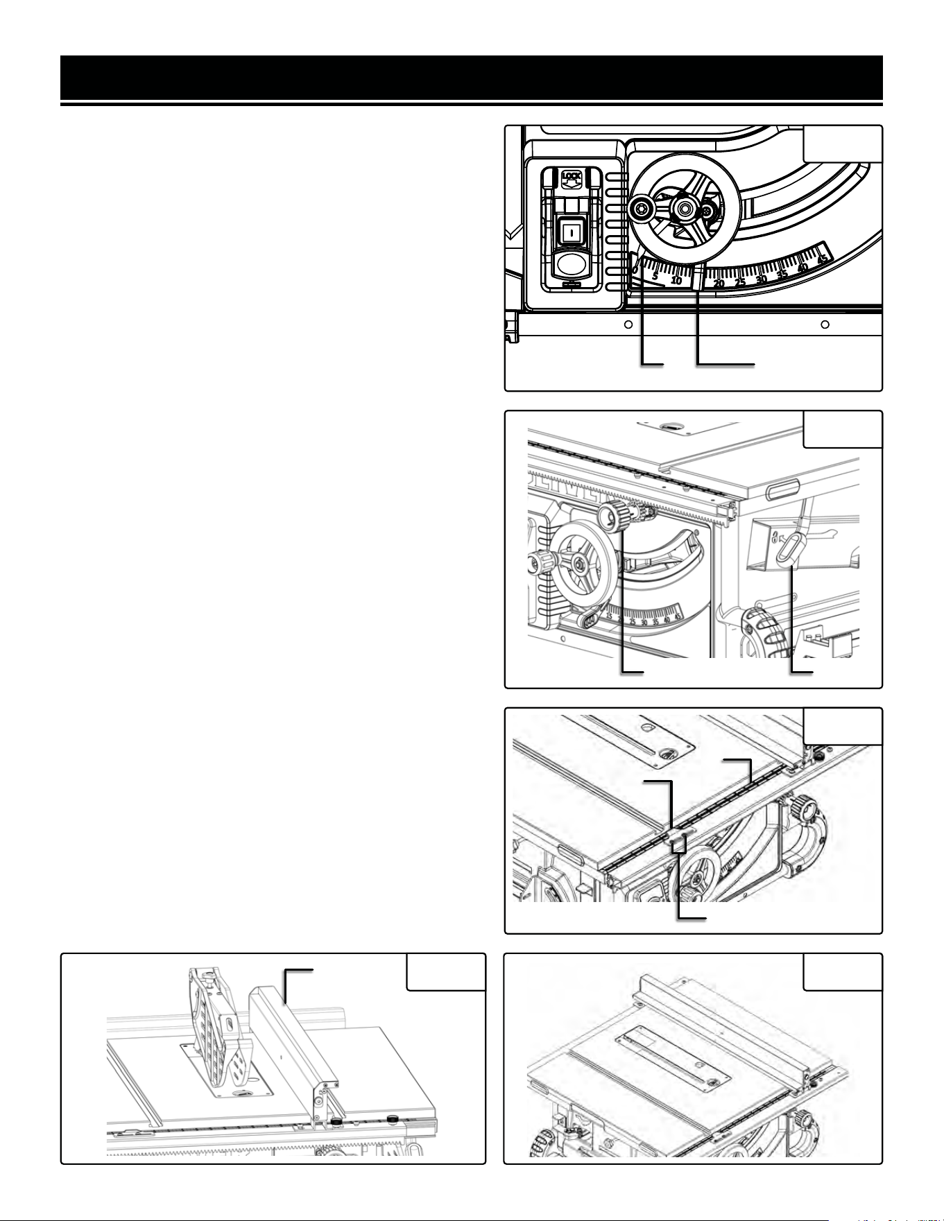
SWITCH ASSEMBLY
This machine is equipped with a magnetic switch to prevent
the saw from being damaged by overload. It also includes a
red paddle for quick emergency stops, if necessary. Finally,
a flip-down tab is provided to prevent unauthorized access
to the green ON button 14). Slide a padlock through the
sides of the switch housing and the flip-down tab for maxi-
mum protection.
CHANGING THE BLADE DEPTH
Loosen the center locking knob, then turn the handwheel
clockwise to raise the blade, or counterclockwise to lower
the blade. Once the blade is at the desired height, tighten
the center locking knob to lock it in place (Fig. 15).
OPERATION
Green ON
Button
Red OFF
Button
Fig. 15
Locking
Knob
Height
Adjustment
Wheel
16
(Below Red Paddle)
17
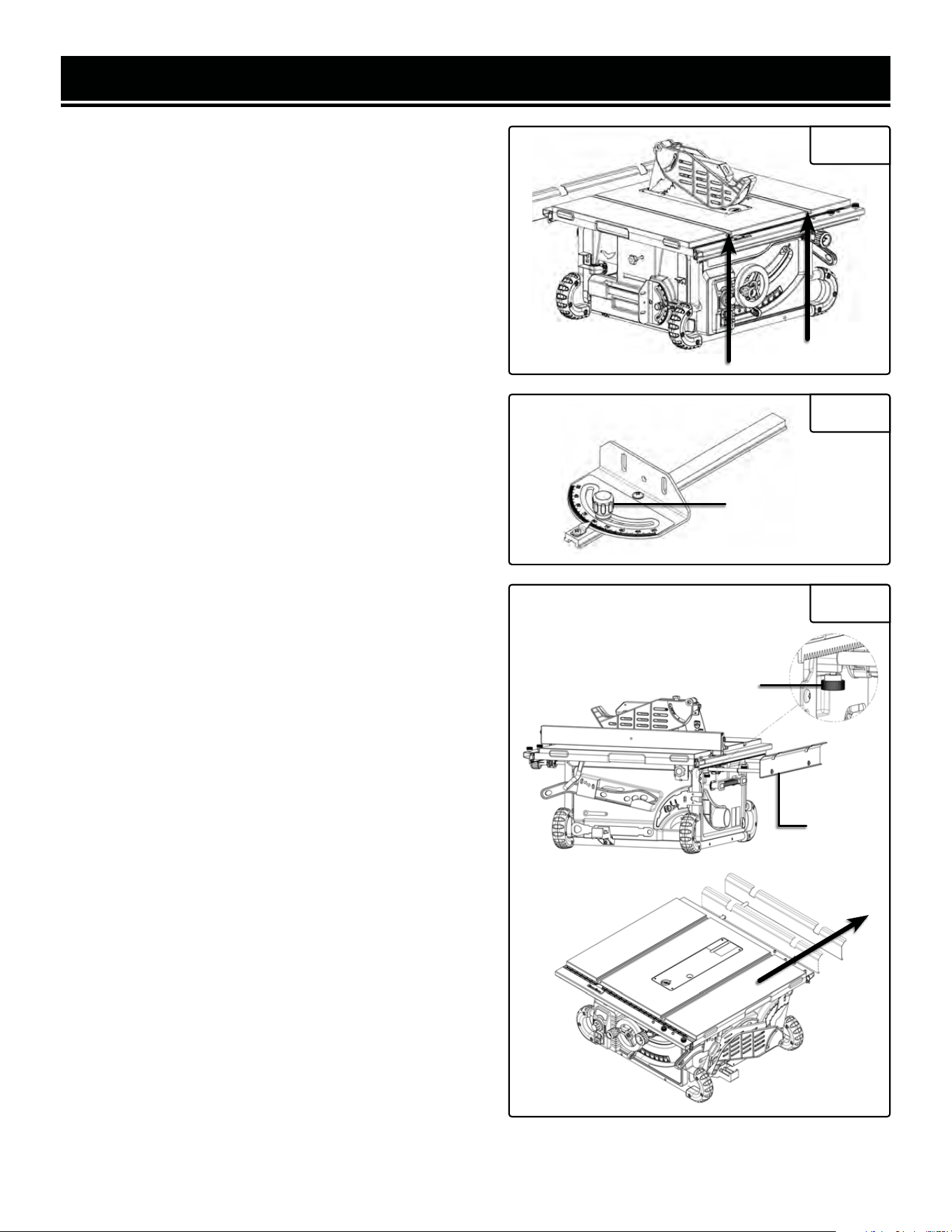
BEVELING THE BLADE
To bevel the blade, move the blade bevel locking lever (Fig.
16 - 1) up to release the locking mechanism. Adjust the
blade bevel using the pointer (Fig. 16 - 2) and scale. Once
the blade is in the desired position, lock the blade in place
by moving the blade bevel locking lever down.
FENCE POSITION
Pull the fence lock lever (Fig. 17 - 2) up to unlock the fence.
Turn the fence adjustment knob (Fig. 17 - 1) to move the
fence left or right. Push down on the fence lock lever to
lock the fence in place.
FENCE SCALE
The fence scale (Fig. 18 - 1) and pointer (Fig. 18 - 2) shows
the distance between the blade and the left edge of the
fence. The fence scale has two scales - one for the inner
fence position, and one for the outer. Ensure that you're
referring to the correct scale depending on the fence posi-
tion.
The fence scale has been calibrated at the factory. How-
ever, if you find that you need to make adjustments, unlock
the fence, loosen the two fence scale screws (Fig. 18 - 3),
adjust the fence as necessary, then tighten the screws and
lock the fence down.
AUXILIARY FENCE
This saw comes with an L-shape auxiliary fence (Fig. 19
- 1) for narrow rip cuts. When ripping material 1/8” or thin-
ner, to prevent workpieces from slipping under the fence,
the auxiliary fence must be used. Swing the auxiliary fence
down toward the blade side of the fence. Figure 20 shows
the auxiliary fence in use. When done, replace the auxiliary
fence atop the fence, making sure it sits securely on the pin
at the end of the fence.
OPERATION
Fig. 16
12
Fig. 17
1 2
Fig. 18
2
1
3
1
Fig. 19 Fig. 20
MITER GAUGE
The miter gauge can be positioned on either side of the
blade, as shown in Fig. 21. To change the angle, loosen
the knob on the gauge (Fig. 22 - 1) and set it to the desired
angle, then tighten the knob.
REAR EXTENSION
When ripping longer workpieces, the rear extension (Fig.
23 - 1) can be extended for extra support. Loosen the two
knobs (Fig. 23 - 2) under the rear extension, and pull the
extension outward. Then, tighten the knobs to secure the
extension.
OPERATION
Fig. 21
Fig. 22
1
Fig. 23
1
2
18
19
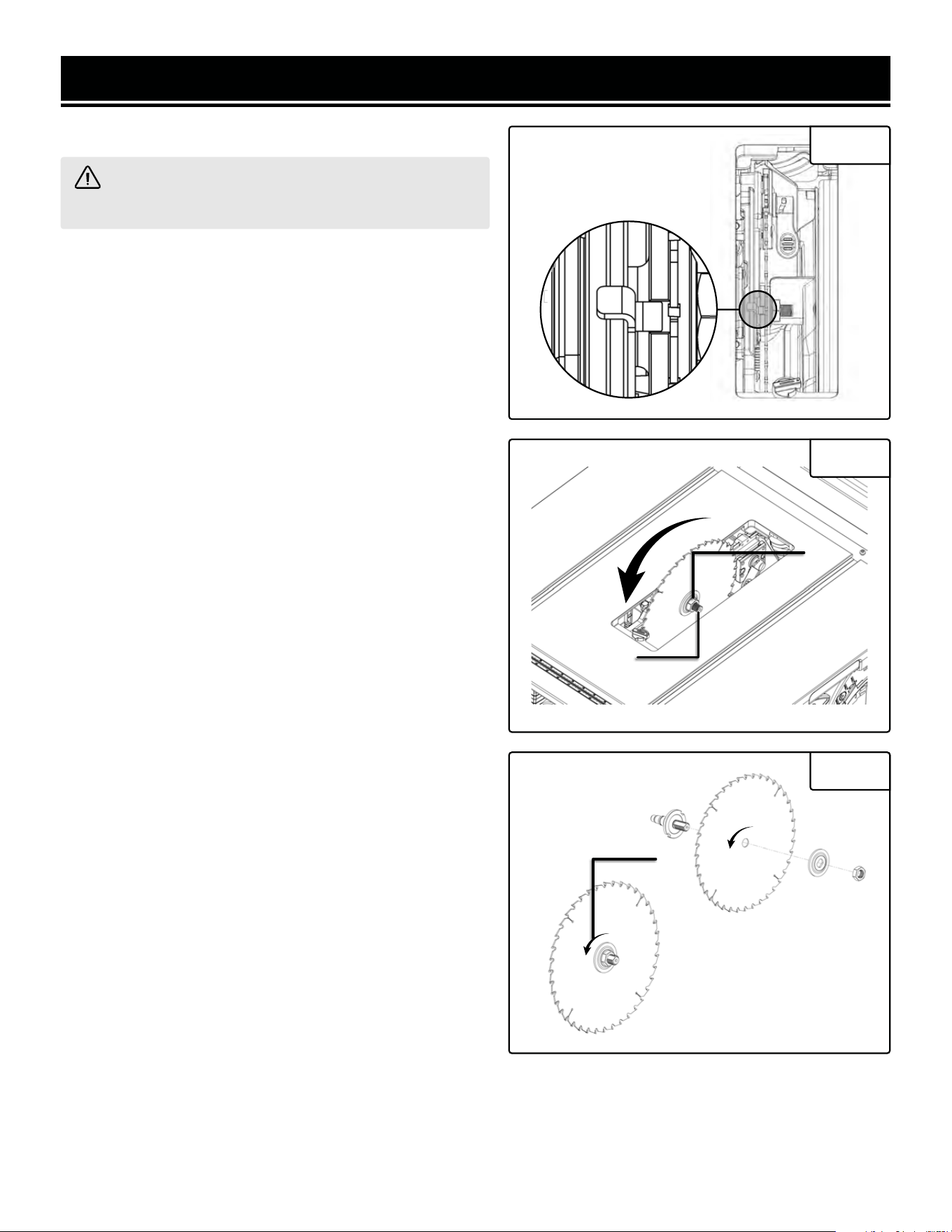
1. Remove the blade guard assembly. See page 11.
2. Raise the blade all the way up, and remove the table
insert.
3. Push the arbor lock (Fig. 24) in and rotate the blade until
it locks in place. This will prevent the blade from turning.
4. While holding the arbor lock (Fig. 25 - 1), use the in-
cluded arbor wrench or a 23mm combination wrench to
loosen and remove the arbor nut (Fig. 25 - 2). Remove the
blade flange and the blade.
5. Install the new blade on the arbor, with the directional
arrows (Fig. 26 - 1) on the blade matching the arrow on the
inside of the blade housing (that is, so the teeth point down
at the front of the saw). Install the flange and arbor nut.
Securely tighten the nut. (Fig. 26).
OPERATION
Fig. 24
WARNING! The blade is very sharp. Wear cut-proof
gloves when handling the blade.
REPLACING THE SAW BLADE
Arbor Lock
Fig. 25
1
2
Fig. 26
1
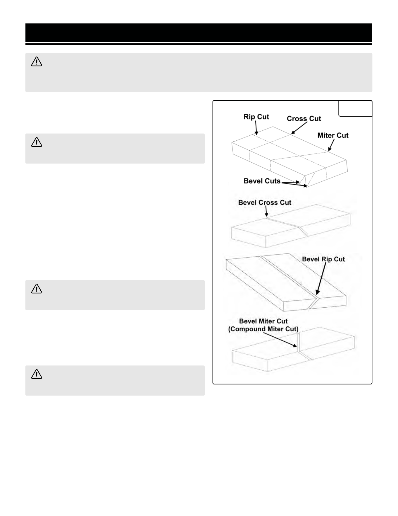
CROSSCUTTING
Crosscutting is to cut a workpiece across its main grain or
its width. Follow the steps below to make a cross cut.
OPERATION
Fig. 27
WARNING! Serious injury can be caused by kickback. Kickback can occur when tension is created between
a workpiece sitting against the fence and the blade. This can cause the workpiece to be thrown toward the
operator or bystanders. To prevent kickback, review the "SPECIFIC RULES FOR YOUR TABLE SAW" section.
WARNING! Disconnect the machine from the power
source before performing the following steps.
1. Remove the fence assembly.
2. Set the blade height 1/8” higher than the top of the work-
piece.
3. Set miter gauge to 0° and place it in the desired slot.
4. Hold the workpiece firmly against the miter gauge with
the blade path aligned with the desired cutting location.
Leave the workpiece at least an inch away from the blade.
5. Connect the machine to power and start the machine,
and allow the blade to come up to full speed.
WARNING! Keep both hands away from the blade
and the path of the blade.
6. Keep the workpiece firmly against the face of the miter
gauge while holding the workpiece flat against the table.
7. Slowly push the workpiece through the blade until the
workpiece is pushed completely past the blade.
WARNING! Never pull the workpiece while the
blade is turning.
8. Turn off the table saw, allow the blade to come to a com-
plete stop, and carefully remove the workpiece.
20
21
OPERATION
Fig. 28
WARNING! Disconnect the machine from the power
source before performing the following steps.
BEVEL CROSSCUTTING
Bevel Crosscutting is to cut a workpiece across its main
grain or its width with an angle other than 0°. The operation
is the same as crosscutting except with an angle. A bevel
crosscut is shown in Fig. 28.
WARNING! Keep both hands away from the blade
and the path of the blade.
1. Remove the fence assembly.
2. Set blade height 1/8” higher than the top of the workpiece.
3. Set miter gauge to 0° and slide its rail to the desired slot.
4. Tilt the blade to desired angle (see page 17, "BEVELING THE BLADE").
5. Hold the workpiece firmly against the miter gauge with the blade path aligned with the desired cutting location.
Leave the workpiece at least an inch away from the blade.
6. Slowly push the workpiece through the blade until the workpiece is pushed completely pass the blade.
7. Turn off the table saw, allow the blade to come to a complete stop, and carefully remove the workpiece.
RIPPING
Ripping is to cut a workpiece along its main grain or its length. Follow the steps below to make a rip cut.
CAUTION! Workpiece must have a straight edge placed against the fence. DO NOT make rip cuts in warped,
twisted, or bowed workpieces.
1. Measure the workpiece. If the width of the workpiece is between 2 and 6 inches, use the included push stick to
feed the workpiece. If the width of the workpiece is less than 2 inches, use the auxiliary fence.
NOTE: When ripping longer workpieces, use the rear extension for extra support.
2. Remove the miter gauge. Set the fence to the desired cut width and lock the fence in place.
3. Set blade height 1/8” higher than the top of the workpiece.
4. Hold the workpiece firmly against the fence with the blade path in line the desired cutting location. Leave the
workpiece at least an inch away from the blade.
5. Have the push stick ready.
6. Plug the saw in and start the saw.
7. Use the push stick to slowly push the workpiece through the blade until the workpiece is completely past the
blade.
8. Turn off the table saw, allow the blade to come to a complete stop, and carefully remove the workpiece.
OPERATION
Fig. 29
WARNING! Disconnect the machine from the power
source before performing the following steps.
BEVEL RIPPING
Bevel ripping is to cut a workpiece along its main grain
or its length with an angle other than 0. This operation is
same as ripping, except that the rip cut is at an angle. Fol-
low the steps below to make a bevel rip cut. A bevel rip cut
is shown in Fig. 29.
WARNING! Keep both hands away from the blade
and the path of the blade.
WARNING! Never make cuts narrower than 3/4
inch when bevel ripping to avoid injury.
1. Measure the workpiece. If the width of the workpiece is between 2 and 6 inches, use the included push stick to
feed the workpiece. If the width of the workpiece is less than 2 inches, use the auxiliary fence.
NOTE: When ripping longer workpiece, pull the rear extension table for work support.
2. Remove the miter gauge and set the fence to the desired width of cut and lock the fence in place.
3. Set the blade height 1/8” higher than the top of the workpiece.
4. Tilt the blade to the desired angle.
5. Hold the workpiece firmly against the fence with the blade path in line with the desired cutting location. Leave
the workpiece at least an inch away from the blade.
6. Have the push stick ready.
7. Plug the saw in and start the saw.
8. Use the push stick to slowly push the workpiece through the blade until the workpiece is completely past the
blade.
9. Turn off the table saw, allow the blade to come to a complete stop, and carefully remove the workpiece.
22
23
OPERATION
MITERING
A miter cut is the same operation as crosscut except the miter gauge is set at an angle other than 90°.
1. Remove the fence.
2. Set the blade at 0 bevel angle (see page 17, "BEVELING THE BLADE").
3. Set the miter gauge at the desired angle (see page 18, " MITER GAUGE").
4. Raise the blade 1/8” higher than the top of the workpiece.
5. Hold the workpiece firmly against the miter gauge. Leave the workpiece at least an inch away from the blade.
6. Connect the machine to power, start the machine, and allow the blade to come to full speed.
7. Keep the workpiece firmly against the face of the miter gauge while holding the workpiece flat against the table.
8. Slowly push the workpiece through the blade until the workpiece is pushed completely past the blade.
9. Turn off the table saw, allow the blade to come to a complete stop, and carefully remove the workpiece.
WARNING! Disconnect the machine from the power source before performing the following steps.
WARNING! Keep both hands away from the blade and the path of the blade.
BEVEL MITERING
A bevel miter cut, also called a compound miter cut, is a combination
of bevel crosscutting and mitering. Follow the instructions for both
bevel crosscutting and mitering (Fig. 30).
NON-THROUGH CUTTING
A non-through cut is when the saw blade does not cut through the
workpiece. Dado cuts, rabbet, and grooves are non-through cuts. Non-
through cuts are the only type of cuts for which the blade guard as-
sembly must be removed. It has higher risk of kickback.
Fig. 30
WARNING! Serious injury can be caused by kickback. Kickback can occur when tension is created between
a workpiece sitting against the fence and the blade. This can cause the workpiece to be thrown toward the
operator or bystanders. To prevent kickback, review the "SPECIFIC RULES FOR YOUR TABLE SAW" section.
1. Adjust the bevel angle to 0°.
2. Remove blade guard assembly. Install the riving knife (See page 15, " INSTALLING THE BLADE GUARD").
3. Set the blade to the desired depth.
4. Use either the fence or miter gauge, depending on the size of the workpiece and type of cut (e.g. crosscut, rip
cut, etc.).
5. Hold workpiece firmly against fence or miter gauge. Leave the workpiece at least an inch away from the blade.
6. Connect the machine to power, start the machine, and allow the blade to come to full speed.
OPERATION
NON-THROUGH CUTTING (CONT.)
7. Slowly push the workpiece through the blade with the push stick (included), push blocks (not included), and/or
feather board (not included) until the workpiece is pushed completely past the blade.
8. Turn off the table saw, allow the blade to come to a complete stop, and carefully slide the workpiece out.
9. Immediate reinstall the blade guard assembly on the saw.
DADO CUTTING
A dado cut is similar to a non-through cut, in which multiple cuts are
performed in succession to create a slot in the workpiece, called a
dado. Refer to and follow the instructions in "Non-Through Cutting" on
this and the previous page.
Specialized dado blades are also available as aftermarket accessories,
as are specialized throat plates compatible with such dado blades.
WEN offers a dado blade set (model BL088D) and dado throat plate
(model TT1015-DADO), available for purchase at wenproducts.com.
CAUTION! Use extreme caution when dado cutting. Always check dado blade clearance before connecting
the saw to a power source.
CAUTION! Do not stack dado blades thicker than the maximum capacity of 13/16". Do not use dado blades
larger than 8" in diameter.
CAUTION! Follow all instructions included in your dado blade's owner's manual. Failure to do so could
result in serious injury to yourself or others.
Fig. 31
WARNING! Do not use a dado blade set without a special dado throat plate installed! The throat plate
included with your saw is NOT compatible with dado blades.
SAFETY CUTTING ACCESSORIES
Safety cutting accessories for this table saw include the following: push stick (included), push blocks (not in-
cluded), and/or feather board (not included).
DUST COLLECTION
This table saw is equipped with a 2 ½” dust collection port. Connect a dust collector to the port at the rear of the
saw (See " DUST COLLECTION" section on page 16).
24
25
ADJUSTMENTS
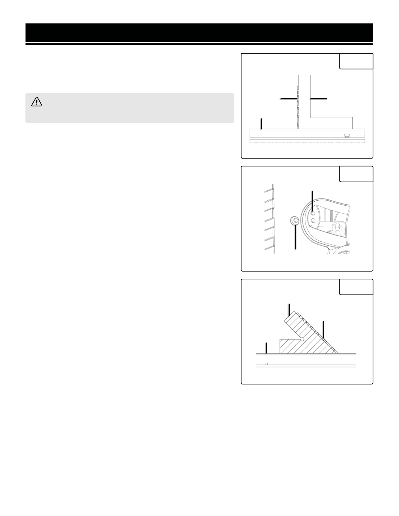
RIVING KNIFE & SAW BLADE ALIGNMENT
WARNING! Disconnect the machine from the power source before performing the following steps.
The riving knife and saw blade alignment has been adjusted at the factory. In most cases, there should not be ad-
justments needed. However, the riving knife and spreader in the blade guard assembly must be aligned with saw
blade during installation.
WARNING! Riving knife and saw blade must align in order to reduce the risk of kickback during operation.
1. Remove blade guard assembly (See page 17, "INSTALL-
ING THE BLADE GUARD").
2. Remove table insert.
3. Raise saw blade to its maximum height.
4. Set the bevel to 0° angle.
5. Place a straightedge against the blade and riving knife
(Fig. 32), first on the bottom of the riving knife, then the top,
to ensure both components are parallel and aligned (Fig. 33).
6. If the riving knife is parallel and aligned with the saw blade,
no adjustment is needed. If not, continue to step 7.
7. If either the top or bottom is not aligned, remove the riving
knife and place it on a flat surface to see if the riving knife is
bent.
8. If the riving knife is bent, straighten it manually. If it can’t
be straightened, call 1-800-232-1195 to order a replacement.
9. If the issue is not a bent riving knife, adjust the screws on
the riving knife block as shown in Fig. 34. Use a 3mm hex
wrench to loosen the 2 cap screws (Fig. 34 - A). Then use
the hex wrench to adjust the 2 top set screws (Fig. 34 - B) for
top alignment adjustments, or the bottom set screws (Fig.
34 - C) for bottom alignment adjustments.
10. To move the knife back or forth, adjust 1 top and 1 bot-
tom set screw on the same side. Do the same for the oppo-
site side. Make sure the riving knife is between 1/8" - 5/16"
(3 - 8mm) away from the blade teeth at all points (Fig. 33).
Do the same for the opposite side.
11. Tighten the cap screws to secure the knife in place.
12. Repeat steps 3 - 6 to ensure the blade and riving knife are
aligned. Adjust as needed. Once the blade and riving knife
are aligned, remove the riving knife.
Top Alignment
Bottom Alignment
Fig. 33
Fig. 32
Fig. 34
B
A
C
B
A
C
ADJUSTMENTS
RIVING KNIFE & SAW BLADE ALIGNMENT (CONT.)
13. Reinstall the table insert.
14. Reinstall the blade guard assembly.
FENCE AND SAW BLADE ALIGNMENT
WARNING! Disconnect the machine from the power
source before performing the following steps.
1. Remove the blade guard (See "INSTALLING THE BLADE
GUARD" on page 15).
2. Raise saw blade to its maximum height.
3. Set the bevel to 0° angle.
4. Slide the fence over until it contacts the saw blade (Fig.
35).
5. Check to see if they are parallel to each other. If they are
not, continue to step 6.
6. Use a 4mm hex wrench to loosen the screws on the
fence knob bracket (Fig. 36). Adjust the bracket until the
fence and blade are parallel, then tighten the screws.
7. Once adjustment is done, reinstall the blade guard.
WARNING! Fence and saw blade must align in
order to reduce the risk of kickback during operation.
Fig. 35
Fig. 36
FenceSaw Blade
Upside down
view of the
Table Saw
26
27
ADJUSTMENTS
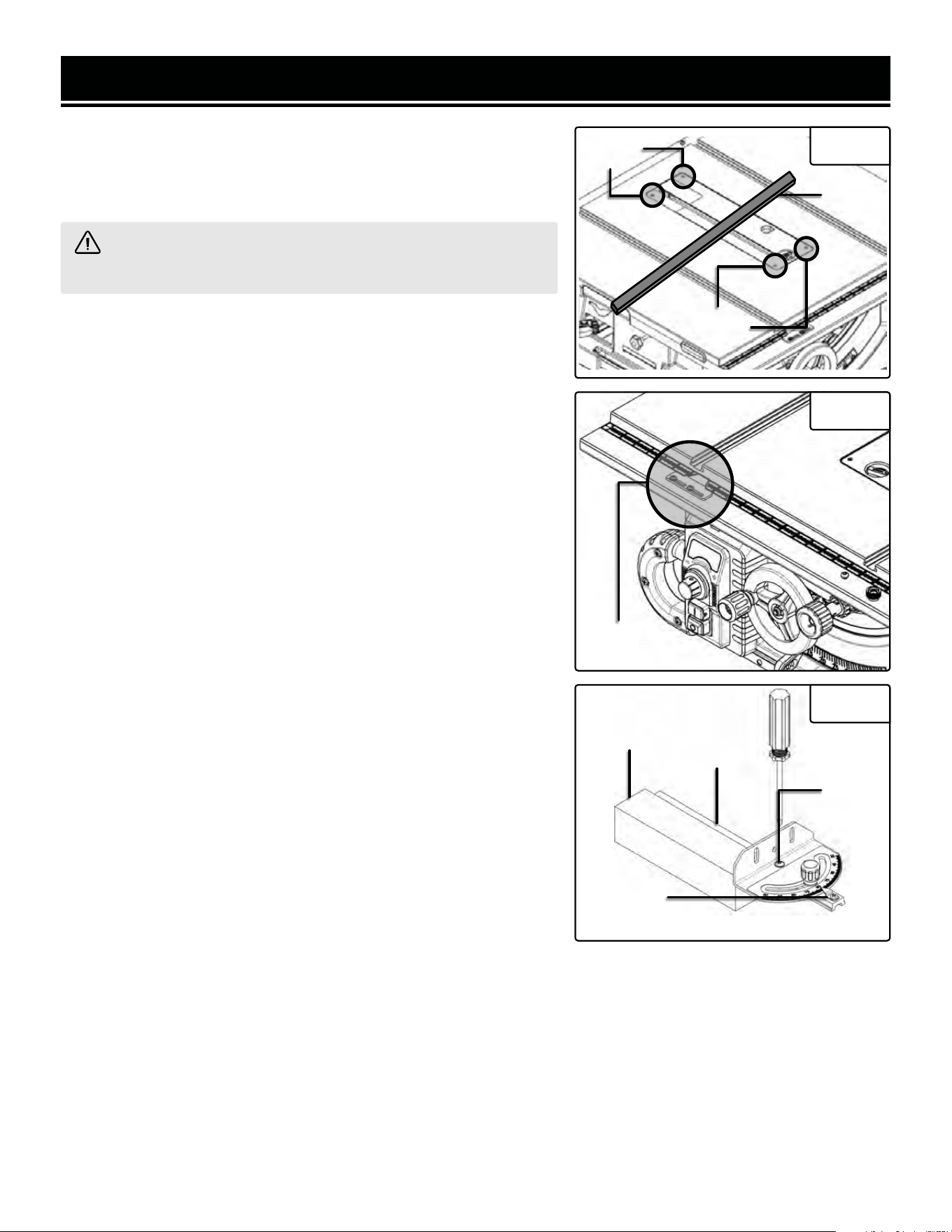
MITER GAUGE SLOT AND BLADE ALIGNMENT
For the best results, the miter slot should be adjusted parallel to the
blade. This is done at the factory, but if it is not exactly parallel, fol-
low the steps below to reduce the risk of kickback.
WARNING! Disconnect the machine from the power source
before performing the following steps.
1. Remove the blade guard (See "INSTALLING THE BLADE GUARD"
on page 15).
2. Raise saw blade to its maximum height.
3. Set the bevel to 0° angle.
4. Use an adjustable square (not included) to measure the distance
from the miter slot to a carbide tip on the blade (Fig. 37). Make sure
that the face of the adjustable square is even along the miter slot.
5. With the end of the adjustable square just touching the tip, lock
the square in place. Mark the carbide tip with a marker (not included)
where you made this measurement.
6. Rotate the marked blade tip to the other end of the table insert.
7. Slide the adjustable square down to the other end of the table in-
sert, and compare the distance from the marked blade tip to the end
of the adjustable square.
• If the blade tip measurement is the same on both sides, the miter
slot is parallel with the table; the procedure is complete.
• If the blade tip measurement is not the same on both sides, the
table will need to be adjusted. Proceed to step 8.
8. To adjust the table, slightly loosen the cap screws in the trunnion
mounting locations (Fig. 38) and slightly tap the trunnions in the
needed direction. Repeat steps 2 through 5 until the blade and miter
slot are parallel.
9. Tighten the trunnion mounting cap screws.
Fig. 37
Fig. 38
Upside down
view of the
Table Saw
ADJUSTMENTS
BEVEL STOP ADJUSTMENT
The bevel stops have been set at the factory, and should not require
adjustments. However, if your cuts are noticeably inaccurate, follow
the steps below to adjust the bevel.
WARNING! Disconnect the machine from the power source
before performing the following steps.
1. Remove the blade guard or riving knife (See "INSTALLING THE
BLADE GUARD" on page 15).
2. Raise saw blade to its maximum height.
To check 90° bevel:
3. Set the bevel to a 0° angle. When the bevel is at 0°, the blade is
at 90°.
4. Place a 90° square between the table and blade to set the blade at
90° (Fig. 39). Make sure the square contacts the top and bottom of
the blade evenly.
5. If the blade is at 90° and the indicator points to 0 degrees, no
further adjustment is needed. If not, go to the next step.
6. Loosen the bevel cam's adjustment screw (Fig. 40).
7. Use the tip of a screwdriver to rotate the cam's adjustment holes
up or down as necessary. Rotate it up to move the bevel stop left;
rotating down moves it right. Use the square on the table as a refer-
ence.
9. Tighten the adjustment screw to secure the bevel cam.
10. Check the square to make sure the adjustment is complete. If
not, repeat steps 4 through 10.
11. Reinstall the blade guard assembly or riving knife.
To check 45° bevel:
3. Set the bevel to 45° angle.
4. Place a 45° triangle square between the table and blade to set the
blade at 45° (Fig. 41).
5. If the blade is at 45° to the table and the pointer is pointing at 45
on the scale, no further adjustment is needed. If not, go to the next
step.
6. Follow the same steps as adjusting the 90 degree bevel cam, us-
ing the 45 degree bevel cam.
Fig. 39
Fig. 40
90º SquareSaw Blade
Table
Adjustment
Holes
Adjustment
Screw
Fig. 41
45º Triangle
Square
Table
Saw Blade
28
29
ADJUSTMENTS
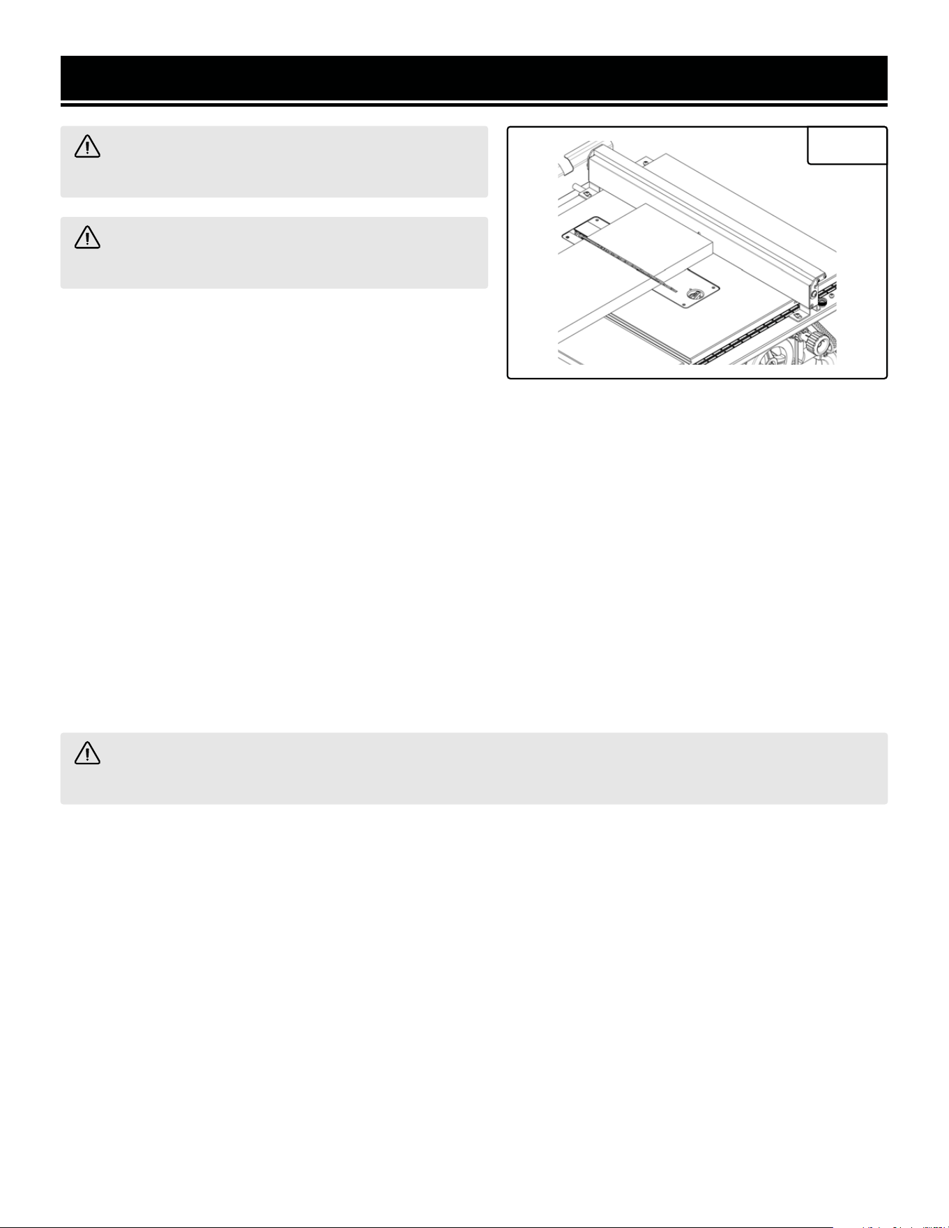
LEVELING TABLE INSERT
The table insert must sit flush with the table in order to provide a
smooth surface to slide the finished workpiece on. To check and
adjust the table insert, follow the steps below.
WARNING! Disconnect the machine from the power source
before performing the following steps.
1. Remove the blade guard (See page 15 for instructions).
2. Place a straight edge on the table insert (Fig. 42). Be sure to check
in both the lengthwise and widthwise directions.
3. If the table insert is flush with the table, no adjustment is needed.
If not, go to step 4.
4. Use a 2.5mm hex wrench to loosen or tighten leveling screws (Fig.
42). Loosening screws lowers the insert; tightening screws raises it.
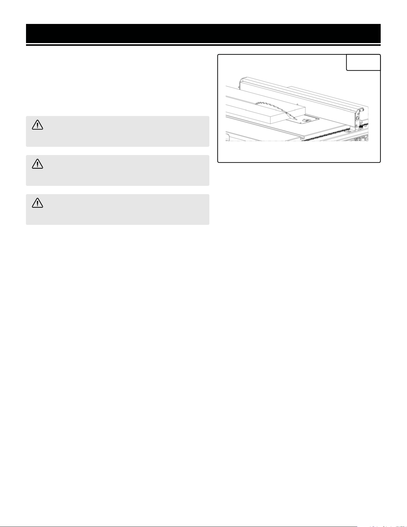
FENCE SCALE ADJUSTMENT
The fence scale shows the dimensions of finished cuts. If your cuts
do not match the scale, follow the steps below.
1. Raise saw blade to its maximum height.
2. Place the fence on the right side of the blade and slide it toward
the blade until the fence just touches the saw blade teeth.
NOTE: Do not push too hard or the blade might deflect.
3. Look at the scale pointer. If the pointer reads 0, no adjustment is
needed. If not, go to the next step.
4. Use a Phillips-head screwdriver (not included) to loosen the two
screws on the pointer, shown in Fig. 43. Slide the pointer until 0 is
shown, then tighten the screws. Then, tighten the screws.
NOTE: When using the auxiliary fence, you may want to reset the
pointer. Slide the auxiliary fence against the blade tips, and set the
pointer to an easy-to-remember number, such as 1". When making a
cut, add 1" to your desired final measurement (e.g. if making a 3.5"
cut, set the scale to 4.5"). Do not forget to reset the pointer when the
auxiliary fence is no longer needed.
Fig. 42
Straight
Edge
Leveling
Screws
Leveling
Screws
Screws
Fig. 43
Fig. 44
Screw
Rail
Straight
Edge
MITER GAUGE
If the angle set on the miter gauge appears to be inaccurate, the gauge's rail and plate may be misaligned. Follow
the steps below to adjust the miter gauge.
1. Use a Phillips-head screwdriver (not included) to loosen the screw (Fig. 44). Place a square between the rail and
plate. Adjust the plate as needed, then tighten the screw.
2. When the rail and plate are at 90 degrees to one another, tighten the screw.
NOTE: If the pointer is inaccurate, loosen the pointer mounting screw (Fig. 44) with the screwdriver, adjust the
pointer, and tighten the screw.
Pointer
Mounting
Screw

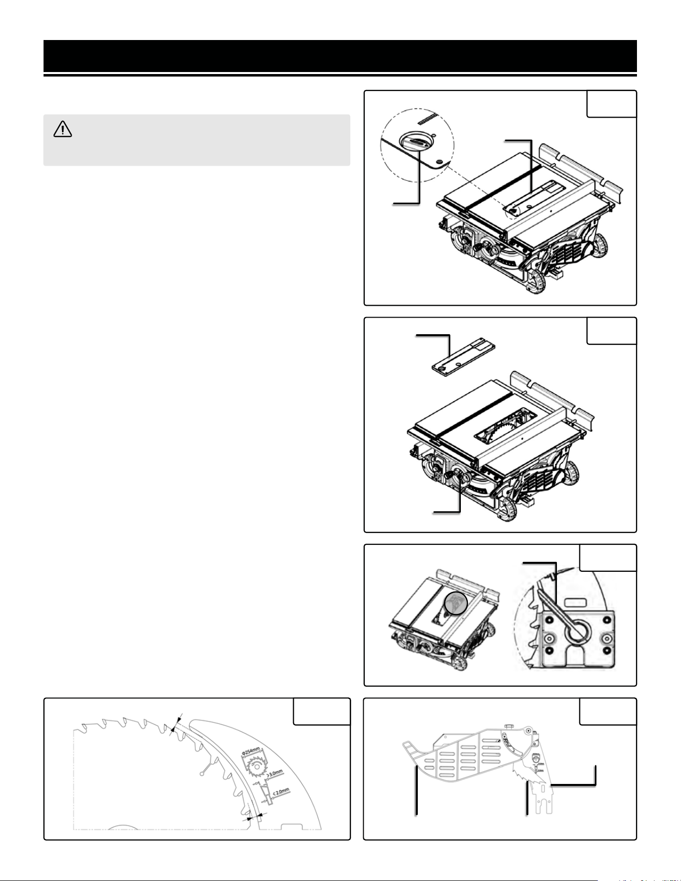
ROUTINE INSPECTION
Before each use, inspect the general condition of the tool. If any of these following conditions exist, do not use until
parts are replaced or the sharpener is properly repaired.
Check for:
• Loose hardware,
• Misalignment or binding of moving parts,
• Damaged cord/electrical wiring,
• Cracked or broken parts, and
• Any other condition that may affect its safe operation
CLEANING
1. Keep the ventilation openings free from dust and debris to prevent the motor from overheating.
2. Periodically clean the inside of the machine for dust control. Use compressed air (not exceeding 25 PSI) to blow
out dust from the motor housing and blade housing.
3. Wipe the tool surfaces clean with a clean cloth. Make sure water does not get into the tool.
4. Every 6 months, use a wire brush to clean dust off the trunnions, gears, blade elevation and fence / rail mecha-
nism and apply a dry lubricant, such as PTFE, to these parts. NOTE: Applying a wet lubricant (e.g. grease, etc.) can
cause sawdust and wood chips to become trapped, decreasing the life of these components.
CARBON BRUSH REPLACEMENT
Replacement carbon brushes (Part No. TT1015-035.14) can be ordered at wenproducts.com. Only genuine WEN
replacement brushes designed specifically for your tool should be used. Carbon brushes are not covered under
the two-year warranty.
1. The carbon brush caps can be accessed on either side of the motor housing.
2. Carefully remove the old carbon brushes using pliers.
3. Install the new carbon brushes. Both carbon brushes should be replaced at the same time.
NOTE: New carbon brushes tend to spark for a few minutes during the first use as they wear down.
MAINTENANCE
WARNING! To avoid accidents, turn OFF and unplug the tool from the electrical outlet before cleaning,
adjusting, or performing any maintenance work.
WARNING! Any attempt to repair or replace electrical parts on this tool may be hazardous. Servicing of the
tool must be performed by a qualified technician. When servicing, use only identical WEN replacement parts.
Use of other parts may be hazardous or induce product failure.
30
31
MAINTENANCE
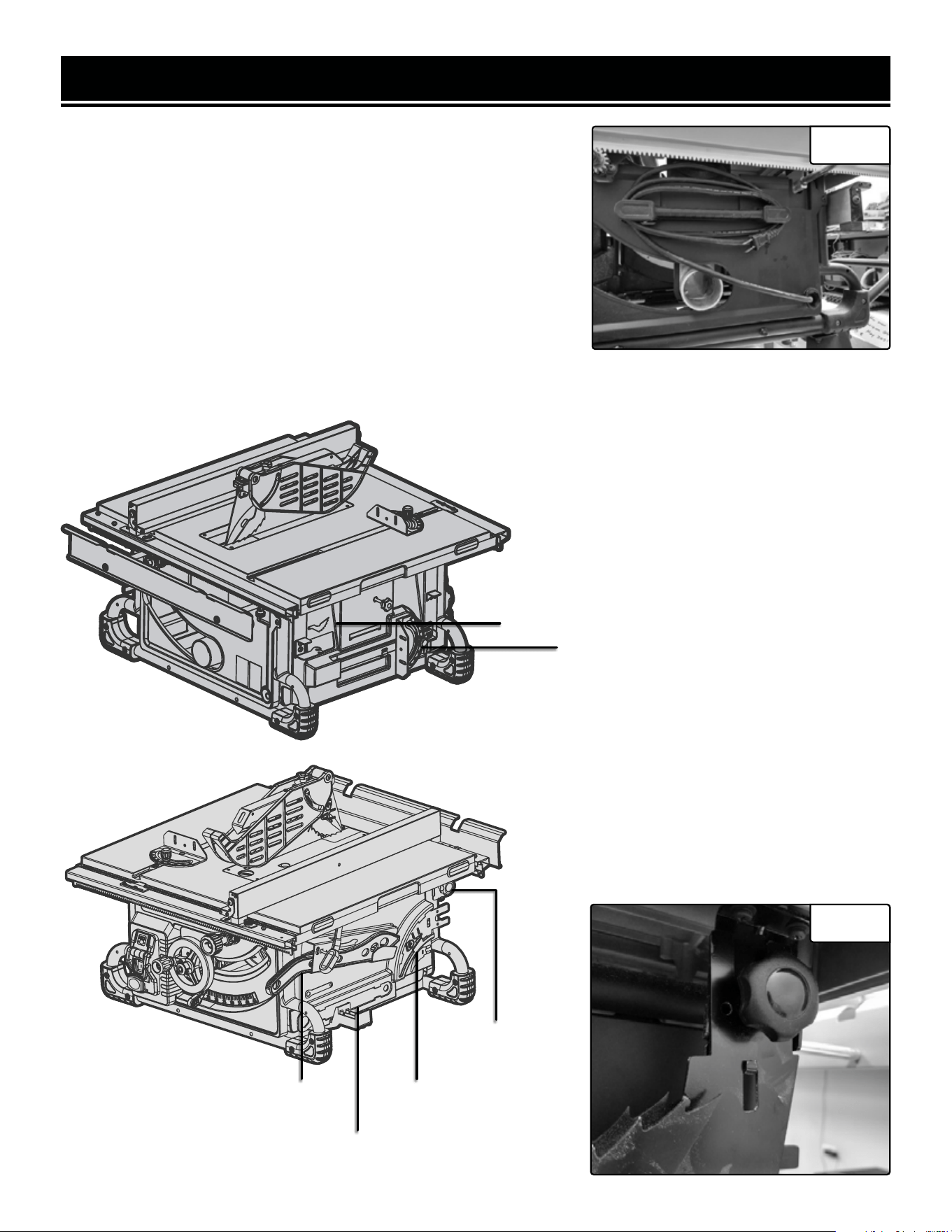
STORAGE
1. Store the tool in a clean and dry place away from the reach of chil-
dren. Store in temperatures between 41° to 86°F.
2. Cover the table saw in order to protect it from dust and moisture.
It is preferable to store it in its original packaging with the instruction
manual.
Accessory Storage
You can store your saw’s accessories on the saw for maximum con-
venience.
The power cord can be wrapped around the cord clip at the back of the
saw (Fig. 45).
Fig. 45
The miter gauge and fence are stored on the left
side of the saw, as shown on page 14.
NOTE: A space is also provided for the anti-
kickback pawls, in case you ever need to remove
them from the blade guard assembly.
Miter Gauge Storage
Anti-Kickback Pawls Storage
The blade wrench, riving knife, blade guard as-
sembly, and push stick are stored on the right
side of the saw, as shown below.
NOTE: When storing the blade guard assembly,
loosen the knob shown in figure 46. Place the
slot in the blade guard spreader over the tab on
the mounting bracket, then tighten the knob to
secure the assembly.
Riving Knife
Storage
Blade Wrench
Storage
Push Stick
Storage
Blade Guard
Assembly Knob
Fig. 46

TROUBLESHOOTING GUIDE
WARNING! Stop using the tool immediately if any of the following problems occur. Repairs and replacements
should only be performed by an authorized technician. For any questions, please contact our customer service
at 1-(800) 232-1195, M-F 8-5 CST or email us at [email protected].
PROBLEM CAUSE SOLUTION
Machine will not
start.
1. Not plugged in. 1. Check connection.
2. Wrong size of extension
cord.
2. Consult extension cord chart on p. 10.
3. Worn carbon brushes. 3. Replace carbon brushes.
4. Faulty power cord, motor, or
switch.
4. Consult WEN customer service at 1(800) 232-
1195.
Blade does not
come up to speed.
1. Blade arbor nut not
tightened.
1. Tighten blade arbor nut.
Does not make
accurate 45° or
90° cuts.
1. Bevel stops not adjusted
correctly.
1. Check blade with combination square and
adjust stops.
2. Angle pointer not set
accurately.
2. Check blade with combination square and
adjust pointer.
3. Fence is not properly
aligned.
3. Adjust fence.
Saw makes
unsatisfactory cuts.
1. Dull Blade. 1. Sharpen or replace blade.
2. Blade mounted backwards. 2. Turn blade around.
3. Gum or pitch on blade. 3. Remove blade and clean.
4. Incorrect blade for cut. 4. Change blade to correct type.
Material binds
blade when
ripping.
1. Fence not aligned with blade. 1. Check and adjust fence.
2. Warped wood. 2. Select another piece of wood.
3. Excessive feed rate. 3. Reduce feed rate.
4. Riving knife or blade guard
not aligned with blade.
4. Align riving knife or blade guard with blade.
32
33
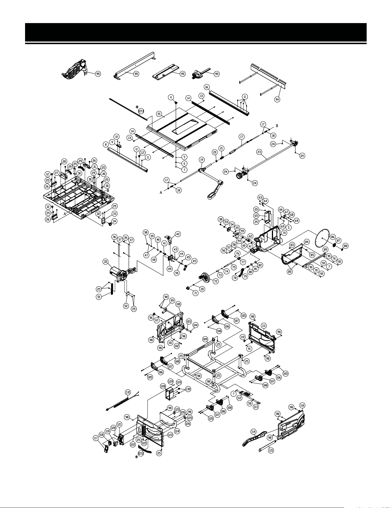
EXPLODED VIEW & PARTS LIST
NOTE: Not all parts may be available for purchase. Parts and accessories that wear
down over the course of normal use are not covered under the warranty.

EXPLODED VIEW & PARTS LIST
No. Part No. Description Qty.
1 TT1015-001ASM
Blade Guard
Assembly
1
2 TT1015-002ASM Fence Assembly 1
3 TT1015-003
Table Insert
Assembly
1
4
Table Insert
Locking Knob
1
5
6mm Wavy
Washer
1
6 6mm Flat Washer 1
7 Lock Nut, M5 1
8 Front Rail 1
9
Fence Scale
Pointer
1
10
Phillips Head
Screw with Flat
Washer, M4-0.7x8
2
11
Socket Button
Head Cap Screw,
M5x3
6
12
Fence Lock Knob,
M5x12
2
13
Phillips Head
Screw with Spring
Washer,
M5-0.8x16
8
14 Rail Mounting Bar 2
15 Table 1
16 Back Rail 1
17 8mm Flat Washer 4
18 Spring 2
19
Fence Lock
Assembly
1
20 9mm Flat Washer 2
21 Spring 1
22
Rear Fence Lock
Shaft
1
23
Rail Adjustment
Rod Assembly
1
No. Part No. Description Qty.
24
Socket Head Cap
Screw with Lock
Washer & Flat
Washer, M5x12
4
25
Phillips Head
Screw with Lock
Washer & Flat
Washer, M5x14
12
26
Extension Table
Bracket
2
27
Rear Trunnion
Bracket
1
28
Socket Head Cap
Screw with Lock
Washer & Flat
Washer, M6x15
4
29 Trunnion Bushing 2
30 Cord Clamp 4
31
Front Trunnion
Bracket
1
32 Acorn Nut, M6 1
33
Blade Guard
Storage Bracket
1
34
Blade Guard
Locking Knob,
M6x25
1
35
Motor & Gearbox
Assembly
1
N.P. TT1015-035.14 Carbon Brush 2
36
Pan Head Phillips
Screw with Flat
Washer and Lock
Washer, M5x22
4
37
Gearbox Support
Rod
2
38 Lock Nut, M8 2
39 9mm Flat Washer 1
40 S Ring STW-14 1
41 Bushing 1
42 TT1015-042 Riving Knife 1
43 Set Screw, M6x8 4
34

35
EXPLODED VIEW & PARTS LIST
No. Part No. Description Qty.
44
Socket Button
Head Cap Screw,
M5x20
2
45 Alignment Pin 1
46 Locking Handle 1
47
Wavy Washer,
8mm
2
48 Spring 1
49
Riving Knife
Locking Plate
1
50 Locking Bolt 1
51 Elevation Rack 1
52 Lower Guard Plate 1
53 9mm Flat Washer 1
54 Elevation Gear 1
55
Elevation Gearbox
Cover
1
56 Cap Screw, M4x8 1
57 Scale Indicator 1
58
Toothed Washer,
4mm
1
59
Gear Box Cover
Bushing
1
60
Spring Pin,
4x25mm
1
61 Bushing 1
62 Worm Gear 1
63 Cap Screw, M5x10 2
64 Spring 1
65 Rear Cover 1
66
Spindle Lock
Spring
1
67 Spindle Lock 1
68 7mm Flat Washer 1
69 Shoulder Screw 3
70 Trunnion 1
71
Elevation Lock
Knob
1
No. Part No. Description Qty.
72
Elevation
Handwheel
1
73 Bushing 1
74 O-ring, P9 1
75 Elevation Shaft 1
76 Set Screw, M5x12 1
77
Elevation Worm
Gear
1
78
Phillips Head
Screw with Lock
Washer, M5x12
1
79 Bevel Lock Lever 1
80
Lock Screw,
M10-1.5x25
(Double Pitch)
1
81
10mm Lock
Washer
1
82
10mm Flat Washer,
Plastic
1
83
Phillips Head
Screw, M5x12
1
84
Trunnion Side
Cover
1
85
Wing Screw with
Lock Washer,
M5x12
3
86 BL1040
Blade, 10", 40T,
5/8" Arbor, 1.6mm
Thickness
1
87 TT1015-087 Blade Flange 1
88 TT1015-088
Blade Nut, 5/8"-12
Double Pitch
1
89 Right Cover 1
90
Phillips Head
Screw with Flat
Washer, M5x10
2
91 4mm Flat Washer 2
92
Self-Tapping
Screw, M4x10
2
93 6mm Flat Washer 3

EXPLODED VIEW & PARTS LIST
No. Part No. Description Qty.
94
Extension Wing
Assembly
1
95 TT1015-095
Miter Gauge
Assembly
1
96
Fence Mounting
Knob, M6
1
97 Lock Nut, M6 1
98
Self-Tapping Screw
M5-2.12x12
19
99
Anti-Kickback Pawl
Mounting Bracket
1
100 Left Cover Panel 1
101 6mm Flat Washer 1
102 Hex Bolt, M6x40 1
103 Cord Clamp 1
104
Self-Tapping
Screw,
M4-1.41x12
2
105
Phillips Head
Screw with Flat
Washer, M5x43
12
106 Frame Bumper 1 4
107 Frame Bumper 2 4
108
Hex Flange Nut,
M5
12
109 Frame 1
110 Cord Bushing 1
111 Rear Cover Panel 1
112
Blade Guard
Bracket
1
No. Part No. Description Qty.
113
Phillips Head
Screw, M5x40
2
114 TT1015-114 Push Stick 1
115 TT1015-115 Blade Wrench 1
116 Right Cover Panel 1
117 Switch Stop Plate 1
118 Switch Lock Plate 1
119 Power Switch 1
120
Switch Stop Plate
Pin
1
121
Switch Mounting
Plate
1
122
Cap Lock Screw,
M5x8
2
123 Front Cover Plate 1
124 Support Plate 1
125 Bevel Stop Cam 2
126
Phillips Head
Screw, M4x6
3
127.2 Bevel Scale Label 1
128 Switch Box 1
129
Self-Tapping
Screw, M4-
1.41x16
8
130 Strain Relief 2
131
Power Cord
(2-Prong, SJ,
14AWG)
1
NOTE: Not all parts may be available for purchase. Parts and accessories that wear
down over the course of normal use are not covered under the warranty.
3636

3737
EXPLODED VIEW & PARTS LISTWARRANTY STATEMENT
WEN Products is committed to building tools that are dependable for years. Our warranties are consistent with this
commitment and our dedication to quality.
LIMITED WARRANTY OF WEN PRODUCTS FOR HOME USE
GREAT LAKES TECHNOLOGIES, LLC (“Seller”) warrants to the original purchaser only, that all WEN consumer power
tools will be free from defects in material or workmanship during personal use for a period of two (2) years from date
of purchase or 500 hours of use; whichever comes first. Ninety days for all WEN products if the tool is used for pro-
fessional or commercial use. Purchaser has 30 days from the date of purchase to report missing or damaged parts.
SELLER’S SOLE OBLIGATION AND YOUR EXCLUSIVE REMEDY under this Limited Warranty and, to the extent per-
mitted by law, any warranty or condition implied by law, shall be the replacement of parts, without charge, which are
defective in material or workmanship and which have not been subjected to misuse, alteration, careless handling,
misrepair, abuse, neglect, normal wear and tear, improper maintenance, or other conditions adversely affecting the
Product or the component of the Product, whether by accident or intentionally, by persons other than Seller. To make
a claim under this Limited Warranty, you must make sure to keep a copy of your proof of purchase that clearly defines
the Date of Purchase (month and year) and the Place of Purchase. Place of Purchase must be a direct vendor of Great
Lakes Technologies, LLC. Purchasing through third party vendors, including but not limited to garage sales, pawn
shops, resale shops, or any other secondhand merchant, voids the warranty included with this product. Contact tech-
[email protected] or 1-800-232-1195 with the following information to make arrangements: your shipping
address, phone number, serial number, required part numbers, and proof of purchase. Damaged or defective parts
and products may need to be sent to WEN before the replacements can be shipped out.
Upon the confirmation of a WEN representative, your product may qualify for repairs and service work. When re-
turning a product for warranty service, the shipping charges must be prepaid by the purchaser. The product must
be shipped in its original container (or an equivalent), properly packed to withstand the hazards of shipment. The
product must be fully insured with a copy of the proof of purchase enclosed. There must also be a description of the
problem in order to help our repairs department diagnose and fix the issue. Repairs will be made and the product
will be returned and shipped back to the purchaser at no charge for addresses within the contiguous United States.
THIS LIMITED WARRANTY DOES NOT APPLY TO ITEMS THAT WEAR OUT FROM REGULAR USAGE OVER TIME,
INCLUDING BELTS, BRUSHES, BLADES, BATTERIES, ETC. ANY IMPLIED WARRANTIES SHALL BE LIMITED IN DU-
RATION TO TWO (2) YEARS FROM DATE OF PURCHASE. SOME STATES IN THE U.S. AND SOME CANADIAN PROV-
INCES DO NOT ALLOW LIMITATIONS ON HOW LONG AN IMPLIED WARRANTY LASTS, SO THE ABOVE LIMITATION
MAY NOT APPLY TO YOU.
IN NO EVENT SHALL SELLER BE LIABLE FOR ANY INCIDENTAL OR CONSEQUENTIAL DAMAGES (INCLUDING BUT
NOT LIMITED TO LIABILITY FOR LOSS OF PROFITS) ARISING FROM THE SALE OR USE OF THIS PRODUCT. SOME
STATES IN THE U.S. AND SOME CANADIAN PROVINCES DO NOT ALLOW THE EXCLUSION OR LIMITATION OF IN-
CIDENTAL OR CONSEQUENTIAL DAMAGES, SO THE ABOVE LIMITATION OR EXCLUSION MAY NOT APPLY TO YOU.
THIS LIMITED WARRANTY GIVES YOU SPECIFIC LEGAL RIGHTS, AND YOU MAY ALSO HAVE OTHER RIGHTS
WHICH VARY FROM STATE TO STATE IN THE U.S., PROVINCE TO PROVINCE IN CANADA AND FROM COUNTRY TO
COUNTRY.
THIS LIMITED WARRANTY APPLIES ONLY TO ITEMS SOLD WITHIN THE UNITED STATES OF AMERICA, CANADA
AND THE COMMONWEALTH OF PUERTO RICO. FOR WARRANTY COVERAGE WITHIN OTHER COUNTRIES, CON-
TACT THE WEN CUSTOMER SUPPORT LINE. FOR WARRANTY PARTS OR PRODUCTS REPAIRED UNDER WARRAN-
TY SHIPPING TO ADDRESSES OUTSIDE OF THE CONTIGUOUS UNITED STATES, ADDITIONAL SHIPPING CHARGES
MAY APPLY.

38
NOTES

39
NOTES

THANKS FOR
REMEMBERING
V. 2021.12.20