4750-WATT
PORTABLE GENERATOR
Instruction Manual
IMPORTANT: Your new tool has been engineered and manufactured to WEN’s highest standards for dependability,
ease of operation, and operator safety. When properly cared for, this product will supply you years of rugged,
trouble-free performance. Pay close attention to the rules for safe operation, warnings, and cautions. If you use
your tool properly and for its intended purpose, you will enjoy years of safe, reliable service.
NEED HELP? CONTACT US!
Have product questions? Need technical support? Please feel free to contact us:
TECHSUPPOR[email protected]1-847-429-9263 (M-F 8AM-5PM CST)
For replacement parts and the most up-to-date instruction manuals, visit WENPRODUCTS.COM
MODEL 56475

CONTENTS
WELCOME 3
Specifications ................................................................................................... 3
Introduction ..................................................................................................... 4
SAFETY 5
General Safety Rules ........................................................................................ 5
Generator Safety Warnings .............................................................................. 7
BEFORE OPERATING 10
Know Your Generator ..................................................................................... 10
Assembly & Adjustments ............................................................................... 12
Generator Preparation .................................................................................... 14
OPERATION & MAINTENANCE 17
Starting the Generator .................................................................................... 17
Stopping the Generator .................................................................................. 18
Subsequent Starting of the Generator ............................................................ 19
Using the Generator ....................................................................................... 20
Maintenance ....................................................................................................23
Storage & Transport ....................................................................................... 28
Troubleshooting Guide ................................................................................... 29
Exploded View & Parts List ............................................................................ 30
Wiring Diagram .............................................................................................. 37
Warranty Statement ....................................................................................... 38
2
To purchase accessories and replacement parts for your tool, visit WENPRODUCTS.COM
Magnetic Oil Dipstick (Model 55201)
Medium Generator Cover (Model 56406)

SPECIFICATIONS
Model Number 56475
Surge (Starting) Wattage 4750 Watts
Rated (Running) Wattage 3750 Watts
Rated Voltage 120V
Phase Single
Frequency 60 Hz
Battery 12V, 7 Ah, Lead-Acid AGM
Product Weight 116 Pounds
Product Dimensions 23.2 in. x 17.6 in. x 18 in.
GENERATOR
Engine Type 4-Stroke OHV Single Cylinder with Forced Air Cooling System
Engine Displacement 224cc
Fuel Tank Capacity 4 Gallons (15.0 L)
Oil Capacity 17.0 fl. oz. (500 mL)
Half-Load Run Time 12.4 Hours
Noise Rating 67 dB Idle, 74 dB Fully Loaded
Spark Plug Type Torch F6TC / NGK BP6ES
Spark Plug Gap 0.7 mm - 0.8 mm (0.028 in. - 0.031 in.)
Spark Plug Torque 1/2 - 3/4 Turn After Gasket Contacts Base or 15 ft. lb
ENGINE
3
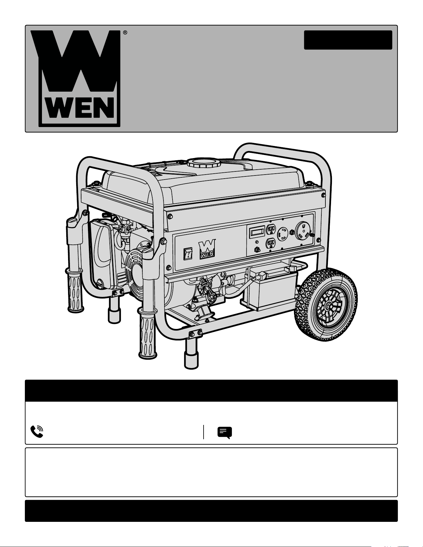
INTRODUCTION
Thanks for purchasing the WEN 4750-Watt Portable Generator. Refer to the illustration below for the location of
the serial number. Record the generator information in the spaces provided below. If assistance for information or
service is required, please contact customer service by calling 1-847-429-9263, M-F 8-5 CST; you will be asked to
provide the following generator information when calling.
Generator Model Number: 56475
Date of Purchase: _______________________________________________
Purchased From: ________________________________________________
Serial Number: _________________________________________________
TO MAXIMIZE THE LIFESPAN OF YOUR GENERATOR: We recommend running your generator at least once a
month for 20 to 30 minutes. Start the generator according to the instructions and plug a small load in to make
sure the outlet is producing electricity.
SERVICE RECORD
Record the service dates of your generator in the chart below. Please perform maintenance checks and operations
according to the “Maintenance” section of the manual.
Service Record Date Date Date Date Date Date
Change Oil
Change Spark Plug
Clean Fuel Tank
Clean Air Cleaner
Clean Spark Arrestor
Serial Number
4

GENERAL SAFETY RULES
WORK AREA SAFETY
1. Keep work area clean and well lit. Cluttered or dark
areas invite accidents.
2. Do not operate power tools in explosive atmo-
spheres, such as in the presence of flammable liquids,
gases or dust. Power tools create sparks which may ig-
nite the dust or fumes.
3. Keep children and bystanders away while operating
a power tool. Distractions can cause you to lose control.
ELECTRICAL SAFETY
1. Power tool plugs must match the outlet. Never mod-
ify the plug in any way. Do not use any adapter plugs
with earthed (grounded) power tools. Unmodified plugs
and matching outlets will reduce risk of electric shock.
2. Avoid body contact with earthed or grounded surfac-
es such as pipes, radiators, ranges and refrigerators.
There is an increased risk of electric shock if your body
is earthed or grounded.
3. Do not expose power tools to rain or wet conditions.
Water entering a power tool will increase the risk of elec-
tric shock.
4. Do not abuse the cord. Never use the cord for car-
rying, pulling or unplugging the power tool. Keep cord
away from heat, oil, sharp edges or moving parts.
Damaged or entangled cords increase the risk of electric
shock.
5. When operating a power tool outdoors, use an ex-
tension cord suitable for outdoor use. Use of a cord
suitable for outdoor use reduces the risk of electric
shock.
6. If operating a power tool in a damp location is un-
avoidable, use a ground fault circuit interrupter (GFCI)
protected supply. Use of a GFCI reduces the risk of elec-
tric shock.
PERSONAL SAFETY
1. Stay alert, watch what you are doing and use com-
mon sense when operating a power tool. Do not use a
power tool while you are tired or under the influence
of drugs, alcohol or medication. A moment of inatten-
tion while operating power tools may result in serious
personal injury.
2. Use personal protective equipment. Always wear
eye protection. Protective equipment such as a respira-
tory mask, non-skid safety shoes and hearing protection
used for appropriate conditions will reduce the risk of
personal injury.
3. Prevent unintentional starting. Ensure the switch is
in the off-position before connecting to power source
and/or battery pack, picking up or carrying the tool.
Carrying power tools with your finger on the switch or
energizing power tools that have the switch on invites
accidents.
4. Remove any adjusting key or wrench before turning
the power tool on. A wrench or a key left attached to a
rotating part of the power tool may result in personal
injury.
5. Do not overreach. Keep proper footing and balance
at all times. This enables better control of the power
tool in unexpected situations.
6. Dress properly. Do not wear loose clothing or jew-
elry. Keep your hair and clothing away from moving
parts. Loose clothes, jewelry or long hair can be caught
in moving parts.
Safety is a combination of common sense, staying alert and knowing how your item works. The term “power tool”
in the warnings refers to your mains-operated (corded) power tool or battery-operated (cordless) power tool.
SAVE THESE SAFETY INSTRUCTIONS.
WARNING! Read all safety warnings and all instructions. Failure to follow the warnings and instructions may
result in electric shock, fire and/or serious injury.
5

GENERAL SAFETY RULES
7. If devices are provided for the connection of dust
extraction and collection facilities, ensure these are
connected and properly used. Use of dust collection
can reduce dust-related hazards.
POWER TOOL USE AND CARE
1. Do not force the power tool. Use the correct power
tool for your application. The correct power tool will
do the job better and safer at the rate for which it was
designed.
2. Do not use the power tool if the switch does not turn
it on and off. Any power tool that cannot be controlled
with the switch is dangerous and must be repaired.
3. Disconnect the plug from the power source and/or
the battery pack from the power tool before making
any adjustments, changing accessories, or storing
power tools. Such preventive safety measures reduce
the risk of starting the power tool accidentally.
4. Store idle power tools out of the reach of children
and do not allow persons unfamiliar with the power
tool or these instructions to operate the power tool.
Power tools are dangerous in the hands of untrained us-
ers.
5. Maintain power tools. Check for misalignment or
binding of moving parts, breakage of parts and any
other condition that may affect the power tool’s opera-
tion. If damaged, have the power tool repaired before
use. Many accidents are caused by poorly maintained
power tools.
6. Keep cutting tools sharp and clean. Properly main-
tained cutting tools with sharp cutting edges are less
likely to bind and are easier to control.
7. Use the power tool, accessories and tool bits, etc.
in accordance with these instructions, taking into ac-
count the working conditions and the work to be per-
formed. Use of the power tool for operations different
from those intended could result in a hazardous situa-
tion.
8. Use clamps to secure your workpiece to a stable
surface. Holding a workpiece by hand or using your
body to support it may lead to loss of control.
9. KEEP GUARDS IN PLACE and in working order.
SERVICE
1. Have your power tool serviced by a qualified repair
person using only identical replacement parts. This
will ensure that the safety of the power tool is main-
tained.
CALIFORNIA PROPOSITION 65 WARNING
Some dust created by power sanding, sawing, grinding,
drilling, and other construction activities may contain
chemicals, including lead, known to the State of Califor-
nia to cause cancer, birth defects, or other reproductive
harm. Wash hands after handling. Some examples of
these chemicals are:
• Lead from lead-based paints.
• Crystalline silica from bricks, cement, and other
masonry products.
• Arsenic and chromium from chemically treated
lumber.
Your risk from these exposures varies depending on
how often you do this type of work. To reduce your ex-
posure to these chemicals, work in a well-ventilated area
with approved safety equipment such as dust masks
specially designed to filter out microscopic particles.
Safety is a combination of common sense, staying alert and knowing how your item works. The term “power tool”
in the warnings refers to your mains-operated (corded) power tool or battery-operated (cordless) power tool.
SAVE THESE SAFETY INSTRUCTIONS.
WARNING! Read all safety warnings and all instructions. Failure to follow the warnings and instructions may
result in electric shock, fire and/or serious injury.
6
GENERATOR SAFETY WARNINGS
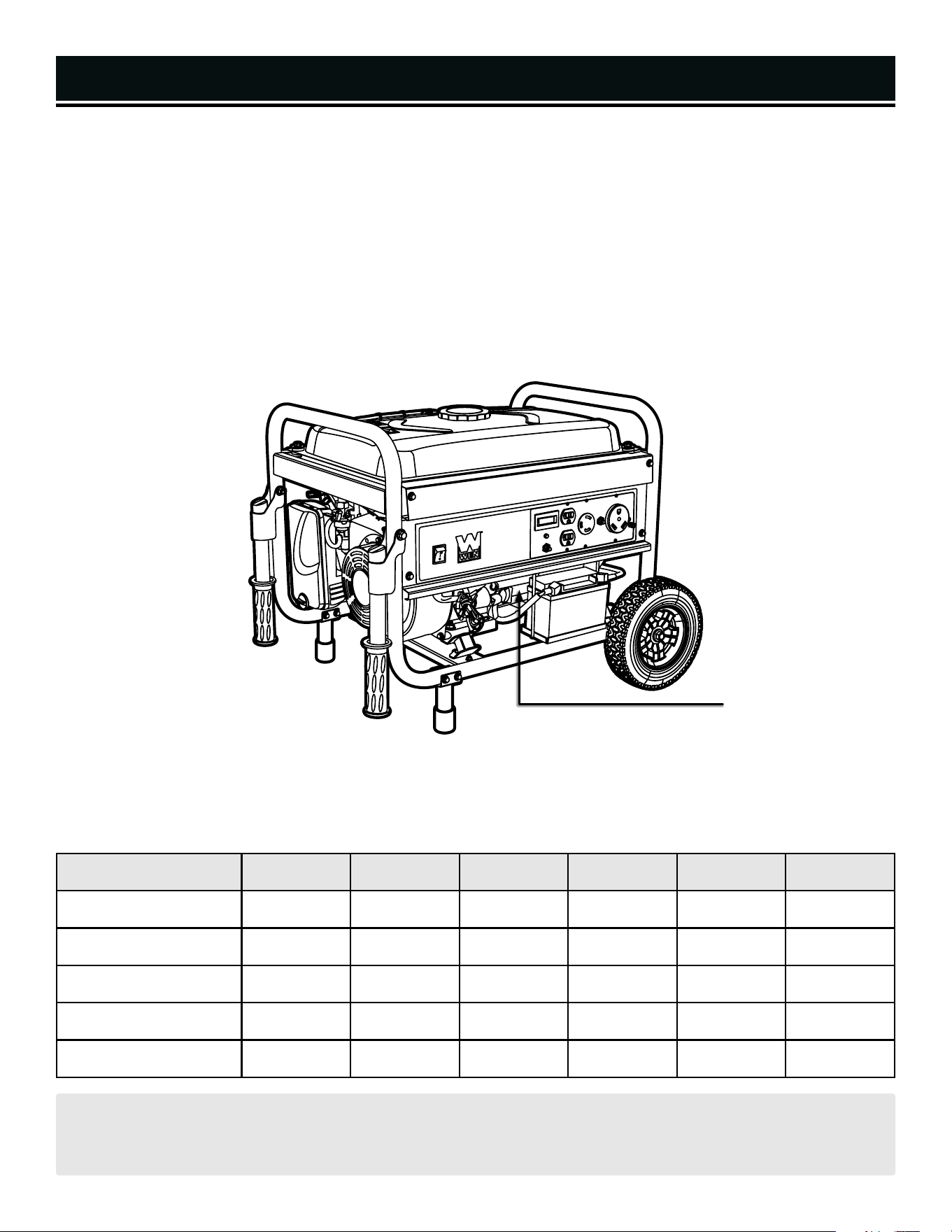
DANGER! CARBON MONOXIDE
Using a generator indoors CAN KILL YOU IN MINUTES. Generator exhaust contains carbon monoxide (CO). This
is a poison gas you cannot see or smell. If you can smell the generator exhaust, you are breathing CO. But even
if you cannot smell the exhaust, you could be breathing CO.
NEVER use a generator inside homes, garages, crawl spaces, or other partially enclosed areas. Deadly levels
of carbon monoxide can build up in these areas. Using a fan or opening windows and doors does NOT supply
enough fresh air. ONLY use a generator outside and far away from windows, doors, and vents. These openings
can pull in generator exhaust.
Even if you use a generator correctly, CO may leak into the home. ALWAYS use a battery-powered or battery-
backup CO alarm in the home. If you start to feel sick, dizzy, or weak after the generator has been running, move
to fresh air RIGHT AWAY. See a doctor. You may have carbon monoxide poisoning.
WARNING! RISK OF EXPLOSION. HIGHLY FLAMMABLE: This generator may emit highly flammable and
explosive gasoline vapors, which can cause severe burns or even death, if ignited. A nearby open flame can lead
to explosion even if not directly in contact with gasoline.
• Do not operate near open flame, heat, or any other ignition source. Do not smoke near the generator.
• Always operate on a firm, level surface.
• Always turn generator off before refueling. Allow generator to cool for at least 2 minutes before removing
fuel cap. Loosen cap slowly to relieve pressure in tank.
• Do not overfill fuel tank. Gasoline may expand during operation. Do not fill to the top of the tank. Allow for
expansion. Always check for spilled fuel before operating.
• If fuel spills, move the generator at least 30 feet away from the spill and wipe clean any spilled fuel before
starting the engine.
• Empty fuel tank before storing or transporting the generator.
WARNING! If this generator is used as a supply for a building’s wiring system, the generator must be in-
stalled by a qualified electrician and connected to a transfer switch as a separately derived system in accordance
with all applicable laws and electrical codes and the National Electrical Code, NFPA 70. The generator shall be
connected to a transfer switch that switches all conductors excluding the equipment grounding conductor. The
frame of the generator shall be connected to an approved grounding electrode.
CALIFORNIA PROPOSITION 65 WARNING: This product contains chemicals and produces exhaust known
to the State of California to cause cancer, birth defects and other reproductive harm. For more information, visit
www.P65Warnings.ca.gov
7

GENERATOR SAFETY
1) Do not operate the generator near an open flame.
2) Do not smoke near the generator.
3) Always operate on a firm, level surface.
4) Always turn the generator off before refueling. Allow
generator to cool for at least 2 minutes before removing
fuel cap. Loosen cap slowly to relieve pressure in tank.
5) Do not overfill fuel tank. Gasoline may expand dur-
ing operation. Do not fill to the top of the tank. Allow for
expansion.
6) Always check for spilled fuel before operating.
7) Empty fuel tank before storing or transporting the
generator.
8) Do not use in rainy conditions.
9) ALWAYS ground the generator before using it (see the
“Ground the Generator” portion of the “Generator Prepa-
ration” section).
10) Generator should only be plugged into electrical de-
vices, either directly or with an extension cord. NEVER
connect to a building’s electrical system without a quali-
fied electrician. Such connections must comply with
local electrical laws and codes. Failure to comply can
create a back-feed, which may result in serious injury or
death to utility workers.
11) Use a ground fault circuit interrupter (GFCI) in highly
conductive areas such as metal decking or steel work.
GFCIs are available in-line with some extension cords.
12) Do not touch bare wires or receptacles (outlets).
13) Do not allow children or non-qualified persons to
operate the generator.
14) Do not touch hot surfaces. Pay attention to warn-
ing labels on the generator identifying hot parts of the
machine.
15) Allow generator to cool down after use before touch-
ing engine or areas of the generator that become hot
during use.
16) Only use generator for its intended purposes.
17) Operate only on dry, level surfaces.
18) Allow generator to run for several minutes before
connecting electrical devices.
19) Shut off and disconnect any malfunctioning devices
from generator.
20) Do not exceed the wattage capacity of the generator
by plugging in more electrical devices than the unit can
handle.
21) Do not turn on electrical devices until after they are
connected to the generator.
22) Turn off all connected electrical devices before stop-
ping the generator.
23) Turn the engine switch to “OFF” position when the
engine is not running.
CAUTION! Misuse of this generator can damage it or
shorten its life.
WARNING! Do not let comfort or familiarity with the product replace strict adherence to product safety rules.
Failure to follow the safety instructions may result in serious personal injury.
GENERATOR SAFETY WARNINGS
WARNING! This generator produces heat when
running. Temperatures near exhaust can exceed
1500 F (650 C).
8

SAVE THESE INSTRUCTIONS
This manual contains important instructions for the WEN generator that should be followed during installation and
maintenance of the generator.
Generators vibrate in normal use. During and after the use of the generator, inspect both the generator as well as
extension and power supply cords for damage resulting from vibration. Have damaged items repaired or replaced
as necessary. Do not use plugs or cords that show signs of damage such as broken or cracked insulation.
For power outages, permanently installed stationary generators are better suited for providing backup power to
the home. Even a properly connected portable generator can become overloaded. This may result in overheating
or stressing of the components, possibly leading to a generator failure..
WARNING! Do not let comfort or familiarity with the product replace strict adherence to product safety rules.
Failure to follow the safety instructions may result in serious personal injury.
GENERATOR SAFETY WARNINGS
WARNING! If this generator is used as a supply for a building’s wiring system, the generator must be in-
stalled by a qualified electrician and connected to a transfer switch as a separately derived system in accordance
with the National Electrical Code, NFPA 70. The generator shall be connected to a transfer switch that switches
all conductors excluding the equipment grounding conductor. The frame of the generator shall be connected to
an approved grounding electrode.
9
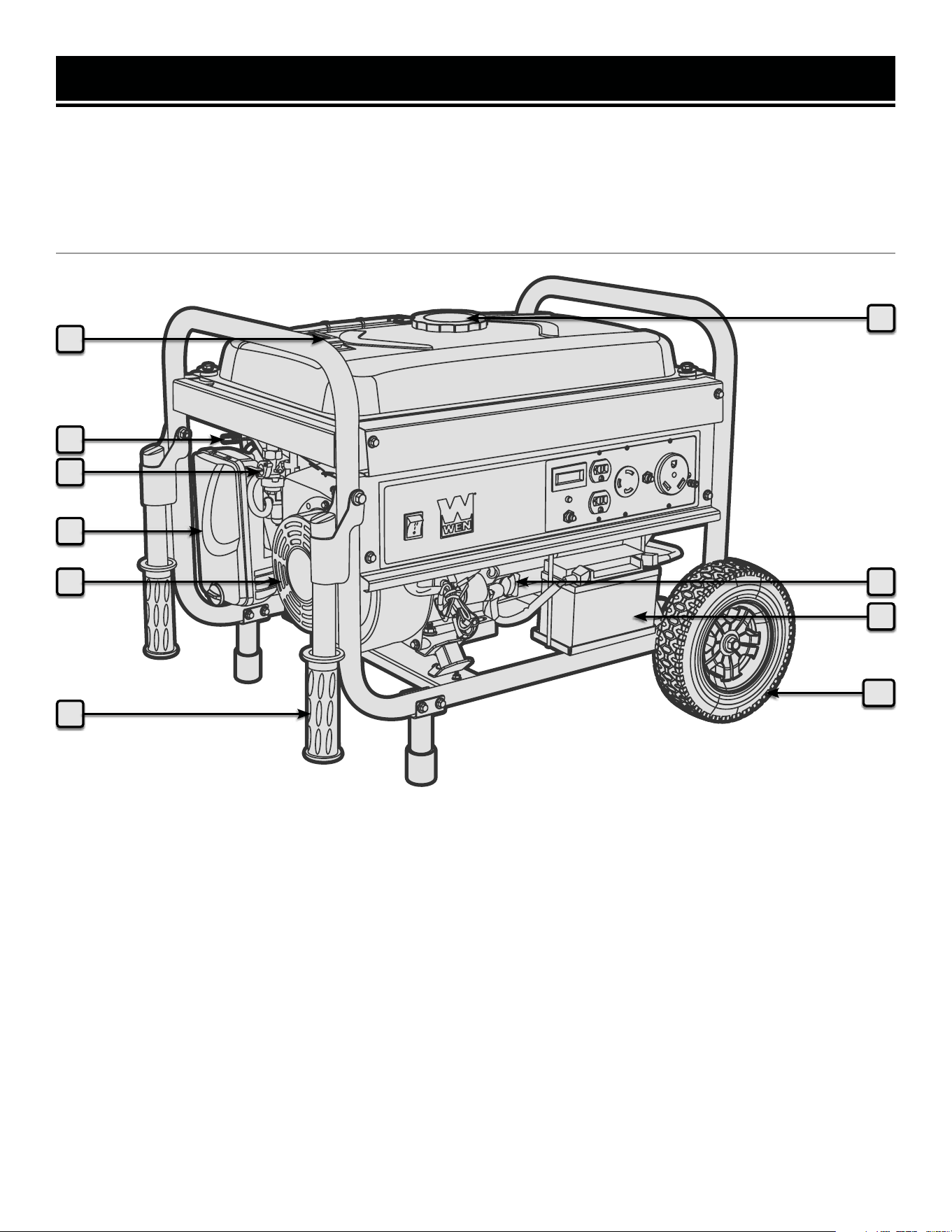
KNOW YOUR GENERATOR
TOOL PURPOSE
Generators provide you with power when and where you need it most. Refer to the following diagrams to become
familiarized with all the parts and controls of your Generator. The components will be referred to later in the manual
for assembly and operation instructions.
GENERATOR
1
7
2
3
4
5
6
9
8
10
1. Fuel Gauge
Indicates the amount of fuel in the tank.
2. Choke Lever
3. Fuel Valve
Allows fuel to enter the engine.
4. Air Cleaner
A removable, cleanable, sponge-like element that limits
the amount of dirt pulled into the engine.
5. Recoil Starter
Pull cord for starting the engine.
6. Handles
For easy transport.
7. Fuel Cap
Access to the fuel tank for adding gasoline.
8. Oil Fill and Dipstick
Location for checking and filling the oil reservoir.
9. 12V Battery
10. 8-Inch Wheels
For easy transport.
10
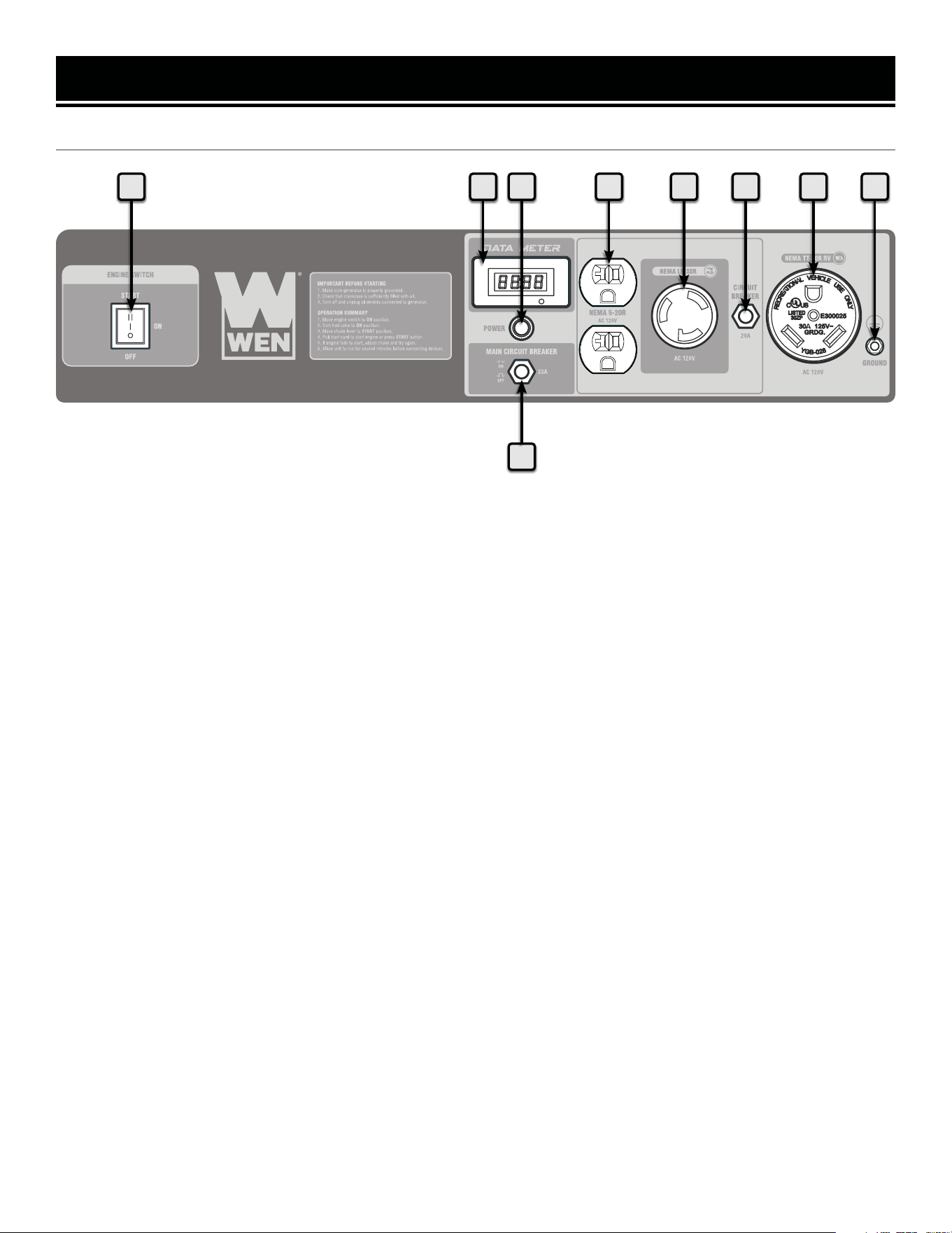
KNOW YOUR GENERATOR
CONTROL PANEL
1 2 3 4 5 6 7 8
9
1. Engine Switch
Start and stop the engine.
2. Digital Engine Hour Counter
3. Power Indicator
Turns green to indicate the output of
power to each receptacle.
4. 120V AC Duplex Receptacle
To connect electrical devices that
run 120V, 60 Hz, single phase AC
current.
5. 120V AC Receptacle
To connect electrical devices that
run 120V, 30A, 60 Hz, single phase,
AC current.
6. 20A Circuit Reset Buttons
Reset button that protect the gen-
erator from electrical overload.
7. 120V 30A RV Receptacle
8. Grounding Nut
9. 33A Circuit Reset Button
Reset button that protects the gen-
erator from electrical overload.
11
ASSEMBLY & ADJUSTMENTS
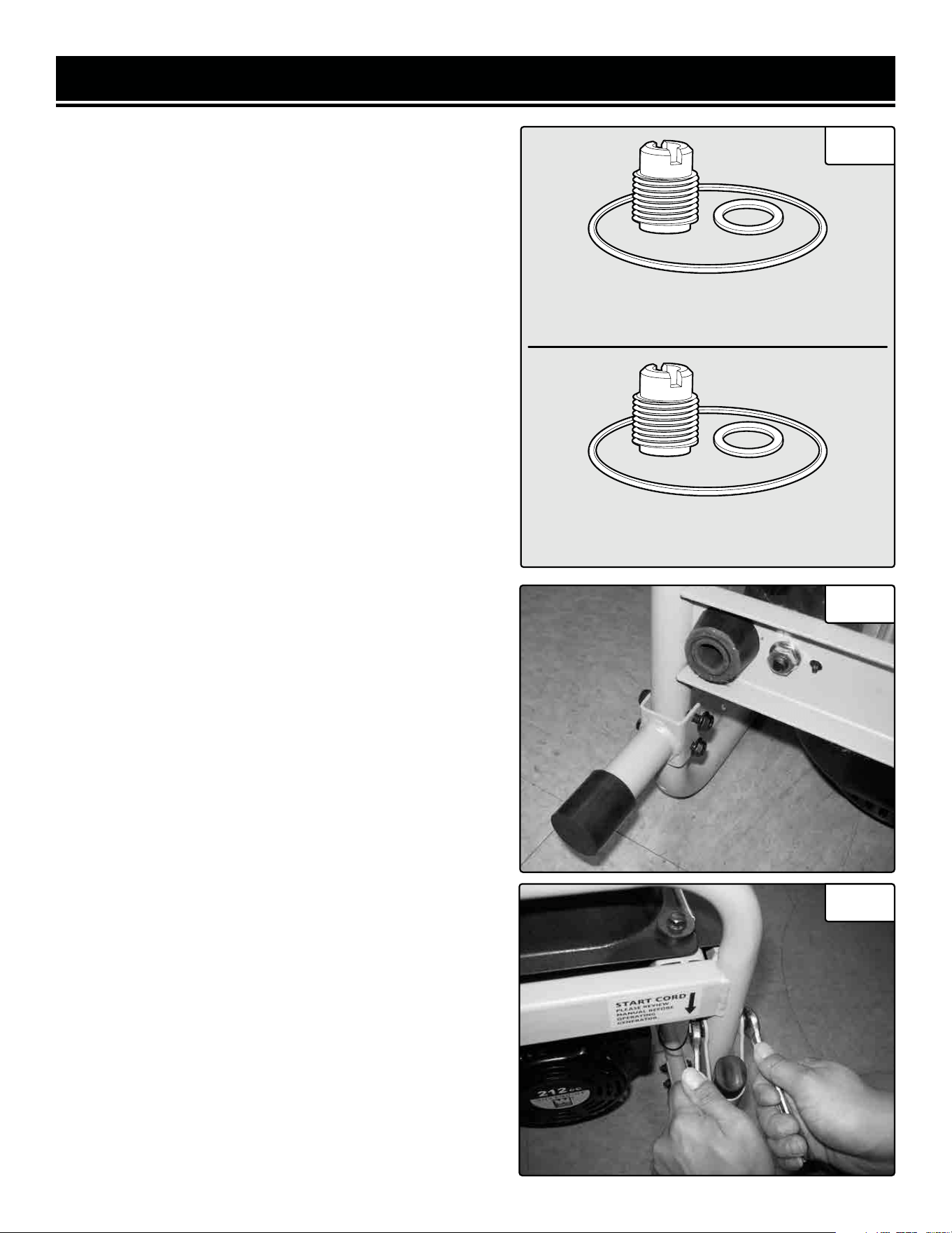
HIGH ALTITUDE OPERATION ABOVE 3000 FEET
Refer to Fig. 1 to gather the proper parts and tools for in-
stalling the high altitude kit (part no. GN5000-HA). Instal-
lation instructions are included with the high altitude kits.
This kit should be installed by a qualified mechanic. Con-
tact customer service at 1-847-429-9263 (M-F 8-5 CST),
or email [email protected] for information
about service centers near you.
The fuel system on this generator may be affected by opera-
tion at high altitudes. Proper operation can be ensured by
installing an altitude kit at altitudes higher than 3000 feet
above sea level. At elevations above 8000 feet, the engine
may experience a decrease in performance, even with the
proper altitude kit. Operating this generator without the high
altitude kit at elevations above 3000 feet may increase the
engine’s emissions and decrease both fuel economy and
performance.
ATTACHING THE FEET (FIG. 2)
1. Stack the two generator wheels on top of each other. Lift
the end of the generator that has the recoil starter onto the
stack of wheels. Be careful not to obstruct any holes on the
generator frame. Feel free to use board or a different reliable
stacking surface instead.
2. Place one leg onto the frame. Line up the holes on the
generator frame with the holes on the bracket portion of the
leg. Tighten using two M6x40 bolts, two M6 nuts, and the
included wrench.
3. Repeat step 2 for the other generator leg.
NOTE: For video instructions visit bit.ly/WHEELKIT
ATTACHING THE HANDLES (FIG. 3)
The handles attach to the generator frame on the same side
as the recoil starter (Left side when facing control panel).
1. Take one handle and line up the holes in the handle brack-
et with the holes on the generator frame.
2. Slide a bolt through the holes in the handle and generator
frame to hold the handle onto the frame.
3. Secure the bolt in place with a nut.
4. Repeat steps 1-3 for the other handle.
At this point, gently remove the two wheels from underneath
the generator.
Fig. 2
12
Fuel Cup Seal (1)
Bolt Seal (1)
Main Jet (1)
Fuel Cup Seal (1)
Bolt Seal (1)
Main Jet (1)
3000 - 6000 ft High Altitude Kit (1)
6000 - 8000 ft High Altitude Kit (1)
Fig. 1
Fig. 3

ASSEMBLY & ADJUSTMENTS
ATTACHING THE WHEELS
1. Find a wood block or similar item that is 3 inches thick
or greater and rest the exhaust end of the generator on the
block (Fig. 4).
2. Take one wheel shaft, and one M12 nut as shown (Fig.
5). Slide the wheel shaft, with the threaded part facing in-
ward, through the frame. Secure using an M12 nut and the
included wrench as shown (Fig. 6).
3. Slide the wheel onto the axle and secure in place using
the nut.
4. Repeat steps 2 and 3 for the other wheel.
At this point, the generator assembly is complete. Gently
remove the generator from the wood block.
Fig. 4
Fig. 5
13
Fig. 6
GENERATOR PREPARATION
The following section describes the necessary steps to prepare the generator for use. If you are unsure about how to
perform any of the steps please call 1-847-429-9263 (M-F 8-5 CST) for customer service. Failure to perform these
steps properly can damage the generator or shorten its life.
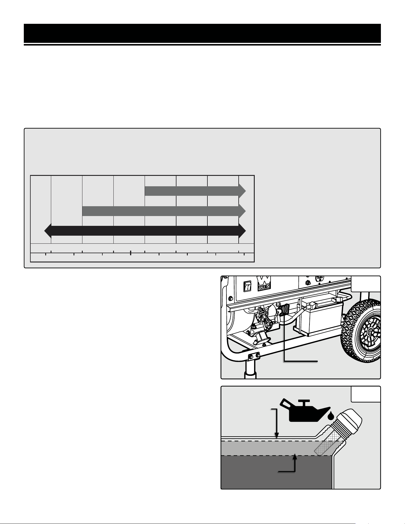
STEP 1 - ADD / CHECK OIL
The generator is shipped without oil. User must add the proper amount of oil before operating the generator for
the first time. The oil capacity of the engine crankcase is 17 fl. oz. For general use (above 40° F), we recommend
30W, 4-stroke engine oil.
TO ADD OIL:
1. Make sure the generator is on a level surface. Tilting the
generator to assist in filling will cause oil to flow into the en-
gine areas and will cause damage. Keep the generator level!
2. Remove the dipstick from the engine (Fig. 7 - 1).
3. Add oil slowly, being careful not to overfill the unit. Fill the
crank case to the upper fill line so the oil lands about halfway
up the dipstick threads (Fig. 8).
4. To check the oil level, wipe the dipstick with a clean rag.
Insert the dipstick into the oil fill opening without screwing it
in. Remove the dipstick to check the oil mark.
5. Slowly add more oil and repeat step 4 until the oil mark
reaches to the top of the dipstick. Do not overfill the crank-
case. The generator is equipped with a low-oil sensor and
will not start without a sufficient amount of oil.
6. Check for oil leaks and firmly tighten the dipstick.
CAUTION! Air cooled engines run
hotter than automotive engines. The
use of non-synthetic multi-viscosity
oils (5W-30, 10W-30, etc.) in tem-
peratures above 40° F will result in
higher than normal oil consumption.
When using a multi-viscosity oil,
check the oil level more frequently
than you would otherwise.
ENGINE OIL RECOMMENDATIONS
Select good quality detergent oil bearing the American Petroleum Institute (API) service classifications SJ, SL,
or SM (synthetic oils may be used). Use the SAE viscosity grade of oil from the following chart that matches
the starting temperature anticipated before the next oil changes.
°F
°C
-20 0 20 32 40 60 80 100
40200
-20
-10
10
-30 30
Upper Fill Line
Lower Fill Line
30W
10W-30
Synthetic 5W-30
Fig. 7
Fig. 8
1
14

GENERATOR PREPARATION
STEP 2 - ADD GASOLINE
Use fresh (within 30 days from purchase), lead-free gasoline with a minimum of 87 octane rating. Do not mix oil
with gasoline.
TO ADD GASOLINE:
1. Make sure the generator is on a level surface.
2. Unscrew fuel cap and set aside.
NOTE: The fuel cap may be tight and hard to unscrew.
3. Slowly add unleaded gasoline to the fuel tank. Be careful not to overfill. The capacity of the fuel tank is 4.0 gallons.
NOTE: Do not fill the fuel tank to the very top. Gasoline will expand and spill over during use even with the fuel cap
in place.
4. Reinstall fuel cap and wipe clean any spilled gasoline with a dry cloth.
WARNING! This generator may emit highly flammable and explosive gasoline vapors, which can cause
severe burns or even death if ignited. A nearby open flame can lead to explosion even if not directly in contact
with gasoline.
IMPORTANT!
• Never use an oil/gasoline mixture.
• Never use old gasoline.
• Avoid getting dirt or water into the fuel tank.
• Gasoline can age in the tank and make starting difficult. Never store generator for extended periods of time
with fuel in the tank.
15
GENERATOR PREPARATION
STEP 3 - CONNECT THE BATTERY
The generator comes with the battery disconnected for safety. To use the electric start, the battery needs to be con-
nected. To connect the battery:
1. Connect the two ends of the battery quick-connector together.
NOTE: If you do not plan to use the generator for a long period of time, it is a good idea to disconnect the quick-
connector for storage. After disconnecting it, cover both exposed ends with an insulator, such as electrical tape, to
help prevent corrosion.
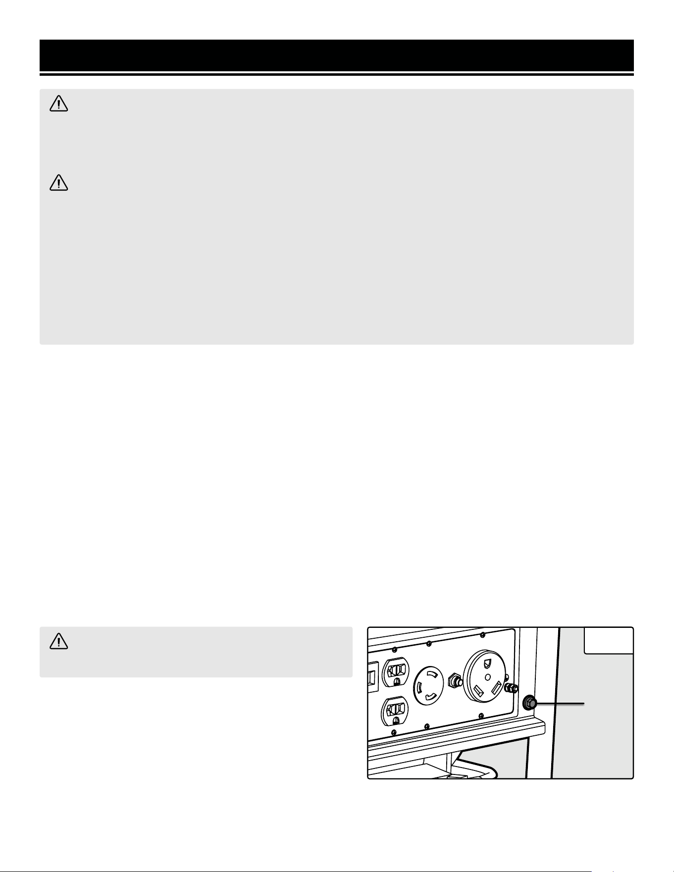
STEP 4 - GROUND THE GENERATOR
Ground the generator by tightening the grounding nut (Fig. 9 - 1) on the front control panel against a grounding
wire. A generally acceptable grounding wire is a No. 12 AWG (American Wire Gauge) stranded copper wire. This
grounding wire should be connected at the other end to a copper, brass, or steel-grounding rod that is driven into
the earth. Wire and grounding rods are not included with the generator.
Grounding codes can vary by location. Contact a local electrician to check the area codes.
NOTE: After completing the above preparation, the generator is ready to be started.
WARNING! Battery gives off explosive hydrogen gas.
• Keep battery away from spark, flame, or cigarette.
• Do not connect or disconnect battery while generator is running.
• Service or use battery only in well ventilated areas.
WARNING! Battery contains sulfuric acid. Battery acid is poisonous. Tilting the generator with the battery
installed can cause battery acid to spill.
• Wear protective clothing and eye wear when servicing battery.
• Keep out of reach of children.
• Do not tilt generator with battery installed.
• If battery acid gets on your skin, wash with water immediately.
• If battery acid gets in your eyes, flush with water for at least 15 minutes and call a doctor immediately.
If battery acid is swallowed, drink a large amount of water or milk. Then drink milk of magnesia or vegetable oil.
Call a doctor immediately.
WARNING! Failure to properly ground the generator
can result in electrocution.
Fig. 9
1
16

STARTING THE GENERATOR
Before starting the generator, make sure you have read and performed the steps in the “Generator Preparation” sec-
tion of this manual. If you are unsure about how to perform any of the steps in this manual please call
1-847-429-9263 M-F 8-5 CST for customer service.
DANGER! CARBON MONOXIDE - USING A GENERATOR INDOORS CAN KILL YOU IN MINUTES.
Using a generator indoors CAN KILL YOU IN MINUTES. Generator exhaust contains carbon monoxide (CO). This
is a poison gas you cannot see or smell. If you can smell the generator exhaust, you are breathing CO. But even
if you cannot smell the exhaust, you could be breathing CO.
NEVER use a generator inside homes, garages, crawl spaces, or other partially enclosed areas. Deadly levels
of carbon monoxide can build up in these areas. Using a fan or opening windows and doors does NOT supply
enough fresh air. ONLY use a generator outside and far away from windows, doors, and vents. These openings
can pull in generator exhaust.
Even if you use a generator correctly, CO may leak into the home. ALWAYS use a battery-powered or battery-
backup CO alarm in the home. If you start to feel sick, dizzy, or weak after the generator has been running, move
to fresh air RIGHT AWAY. See a doctor. You may have carbon monoxide poisoning.
WARNING! The exhaust from this product contains chemicals known to the State of California to cause
cancer, birth defects, or other reproductive harm.
WARNING! This generator may emit highly flammable and explosive gasoline vapors, which can cause se-
vere burns or even death if ignited. A nearby open flame can lead to explosion even if it isn’t directly in contact
with gasoline.
WARNING! This generator produces powerful voltage, which can result in electrocution.
ALWAYS ground the generator before using it (see the “Ground the Generator” portion of the “Generator Prepara-
tion” section).
Generator should only be plugged into electrical devices, either directly or with an extension cord. NEVER connect to
a building electrical system without a qualified electrician. Such connections must comply with local electrical laws
and codes. Failure to comply can create a back-feed, which may result in serious injury or death to utility workers.
Use a ground fault circuit interrupter (GFCI) in highly conductive areas such as metal decking or steel work. GFCIs
are available in-line with some extension cords.
Do not use in rainy or wet conditions. Do not touch bare wires or receptacles (outlets). Do not allow children or
non-qualified persons to operate.
CAUTION! Disconnect all electrical loads from the generator before attempting to start or stop.
17
STARTING THE GENERATOR
STARTING THE ENGINE
1. Unplug all electrical devices from the generator during
ignition. Otherwise it will be difficult for the engine to start.
2. Check that the generator is properly grounded (Ground
the Generator).
3. Check the oil and fuel levels.
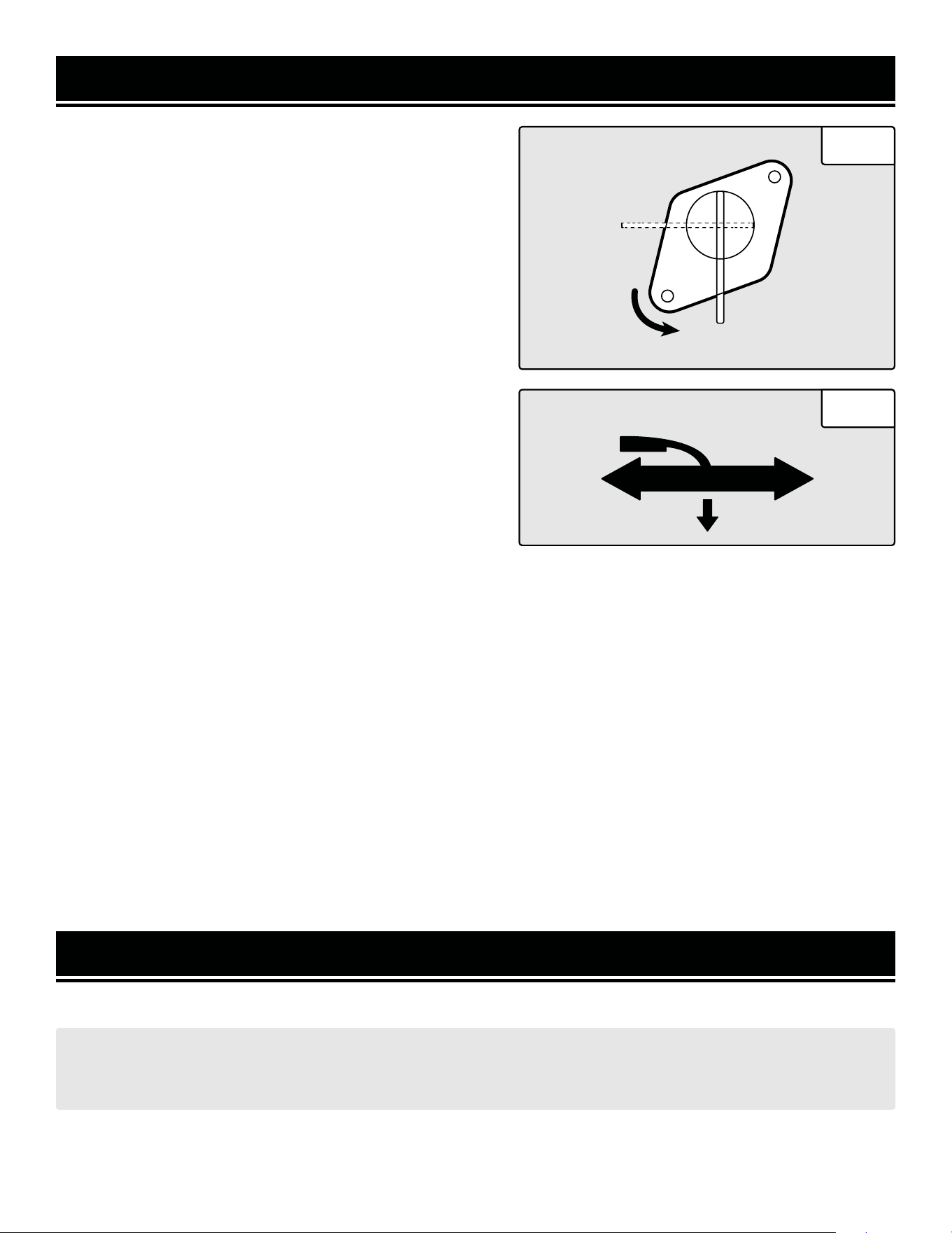
4. Turn the fuel valve to the ON position (Fig. 10).
5. Move the choke lever to CLOSE / START (Fig. 11).
6. Set the ON/OFF Switch to the ON position.
7. Press the engine switch to the “START” position for 2-3
seconds or until the engine starts. NOTE: If the engine does
not start after 2-3 seconds, release the switch from the start
position. Keeping the switch in the START position too long
can damage the starter.
8. If engine fails to start, repeat step 7.
NOTE: After repeated failed attempts to start the engine,
please consult the troubleshooting guide before attempting
OFF
ON
CHOKE LEVER
START RUN
CLOSE OPEN
to start the generator. If problems persist please call 1-847-429-9263, M-F 8-5 CST.
9. Once the engine has started, slowly return the choke lever all the way to the OPEN/RUN position.
10. Allow the engine to run for several minutes before attempting to connect any electrical devices. This allows the
generator to stabilize its speed and temperature.
FOR MANUAL START: Pull on the recoil starter handle slowly until a slight resistance is felt, then pull quickly to start
the engine. Do this instead of step 7. Return cord gently into the recoil starter. Never allow the cord to snap back.
ENGINE BREAK-IN PROCEDURE
The procedure below should be followed when you receive your generator in order to prolong the engine’s service
life. This procedure helps to seat the piston rings properly in the cylinder, and will reduce overall wear on the engine.
For the first 8 hours of operation, vary the load, but keep it at or below 50% of the generator’s rated wattage, if
possible. If your generator is equipped with an Eco-mode switch (only applicable for certain inverter generators),
engage Eco-mode periodically during the first 8 hours. After the first 8 hours, change the oil, then change it again
after the first 25 hours. You may run the generator at full load after the 8-hour oil change. Refer to the Recom-
mended Maintenance Schedule in Table 4 for the full maintenance schedule.
SUBSEQUENT STARTING OF THE GENERATOR
If this is not the first time using the generator, the user should take the following steps to prepare it for operation.
IMPORTANT! At this point the user should be familiar with the procedures described in the sections titled “Start-
ing the Generator” and “Generator Preparation.” If the user has not yet read these sections, go back and read
them now.
Fig. 11
18
Fig. 10

STOPPING THE GENERATOR
TO STOP THE GENERATOR
1. Turn off all electrical devices prior to unplugging them from the generator. Unplugging running devices can cause
damage to the generator.
2. Turn the fuel valve to the “OFF” (horizontal) position.
3. Turn the “ON/OFF” switch to the “OFF” position.
WARNING! Allow generator to cool for several minutes before touching areas that become hot during use.
CAUTION! Allowing gasoline to sit in the fuel tank for long periods of time can make it difficult to start the
generator in the future. Never store the generator for extended periods of time with fuel in the fuel tank. Refer
to Generator Storage Section.
STEP 1 - CHECK THE OIL
Oil consumption is normal during generator use. The generator is equipped with a low oil pressure shutoff to protect
it from damage. The oil level of the engine should be checked before each use to ensure that the engine crankcase
contains sufficient lubricant.
TO CHECK OR ADD OIL:
1. Make sure the generator is on a level surface. Clean
around oil fill.
2. Remove the oil filler/dipstick cap and check the oil level.
3. If the oil level is below the second thread from the lip of
the oil fill opening, slowly add oil until the engine crankcase
is filled.
4. Reinstall and tighten oil cap before starting the engine.
STEP 2 - CHECK THE FUEL LEVEL
Before starting the generator, check to see that there is sufficient gasoline in the fuel tank. Add additional gasoline
as necessary but leave sufficient room in the tank for expansion.
STEP 3 - GROUND THE GENERATOR
IMPORTANT!
• Use only UNLEADED gasoline.
• Do not use old gasoline.
• Never use an oil/gasoline mixture.
• Avoid getting dirt or water into the fuel tank.
WARNING! Failure to properly ground the generator can result in electrocution.
Ground the generator by tightening the grounding nut (Fig. 9) on the front control panel against a grounding wire. A
generally acceptable grounding wire is a No. 12 AWG (American Wire Gauge) stranded copper wire. This grounding
wire should be connected at the other end to a copper, brass, or steel-grounding rod that is driven into the earth.
Wire and grounding rod are not included in generator contents.
Grounding codes can vary by location. Contact a local electrician for area codes.
To maximize the lifespan of this generator, make sure to run it at least once a month. If you do not run it often,
it will greatly shorten the lifespan and performance of the generator.
19
SUBSEQUENT STARTING OF THE GENERATOR

CALCULATING THE WATTAGE OF YOUR DEVICE(S)
Connect electrical devices running on AC current according to their wattage requirements. Calculate the total run-
ning wattage and starting wattage of the device(s) you wish to connect, and MAKE SURE that they are within the
capacity of your generator and the capacity of each individual outlet.
Generator
Wattage
Capacity
GENERATOR RUNNING (RATED) WATTS GENERATOR STARTING (SURGE) WATTS
3750W 4750W
What this means:
The generator can produce a maximum of
3750W on a continuous basis to supply on-
going power to your electronic devices.
NOTE: Also check the rated amperage for
each outlet and make sure not to overload
the individual outlets.
What this means:
Some devices such as box fans require short
bursts of extra power in addition to the rated
wattage listed by the device to start their mo-
tors.
The generator can produce a maximum watt-
age of 4750W for a short period of time
(seconds) to cover the extra starting power
required by your electronic devices.
Electronic
Device
Wattage
Calculation
Find the wattage information of each device you plan to connect. The information should
be listed on the device or in its instruction manual, or you may refer to Table 2 - Estimated
Wattages of Common Electrical Appliances.
The wattage can be calculated using this equation: Watts = Volts x Amperes
To calculate the total running watts of your
devices:
+ Add up the running wattages of all the
device(s) you plan to connect.
= The total running (rated) wattage.
This wattage should NOT exceed the run-
ning wattage of 3750W.
It is recommended to maintain a load at or
below 3375W (90% of the rated output) to
ensure steady voltage output and to prolong
the generator’s lifespan.
To calculate the total starting watts of your
devices:
+ Add up the total running wattage of all the
device(s) you plan to connect.
+ Add the single highest ADDITIONAL start-
ing wattage out of the device(s) you plan to
connect.
= The total starting (surge) wattage.
This wattage should NOT exceed the starting
wattage of 4750W.
If any of either of the total calculated running watts or starting watts is higher than the capac-
ity of your generator, adjust the load until both wattage requirements are met. Otherwise you
will overload the generator, and cause damage to the engine and your electrical device(s).
Table 1 - How to Calculate Wattages
USING THE GENERATOR
20

CALCULATING THE WATTAGE OF YOUR DEVICE(S) - CONTINUED
The chart below serves as a reference for the estimated wattage requirements of common electrical devices. How-
ever, do not solely rely on this chart - all electronics and appliances are built differently. Always check the wattage
listed on the electrical device before consulting this chart.
Tool or Appliance Rated (Running) Watts Surge (Starting) Watts
Hot Plate 2500 0
Saw - Radial Arm 2000 2000
Electric Stove (Each Element) 1500-2800 0
Saw - Circular 1500 1500
Air Compressor (1 HP) 1500 3000
Window Air Conditioner 1200 1800
Saw - Miter 1200 1200
Microwave 1000 0
Well Water Pump 1000 1000
Sump Pump 800 1200
Refrigerator Freezer 800 1200
Furnace Blower 800 1300
Computer 800 0
Electric Drill 600 900
Television 500 0
Deep Freezer 500 500
Garage Door Opener 480 0
Stereo 400 0
Box Fan 300 600
Clock Radio 300 0
Security System 180 0
DVD Player / VCR 100 0
Common Light Bulb 75 0
Table 2 - Estimated Wattages of Common Electrical Appliances
NOTE: Become familiar with the functions and capacity of each component on the control panel before con-
necting electrical devices. See page 11 for more information about the components of the control panel. Do not
overload generator or individual panel receptacles. Do not connect 50Hz or 3-phase loads to the generator.
USING THE GENERATOR
21
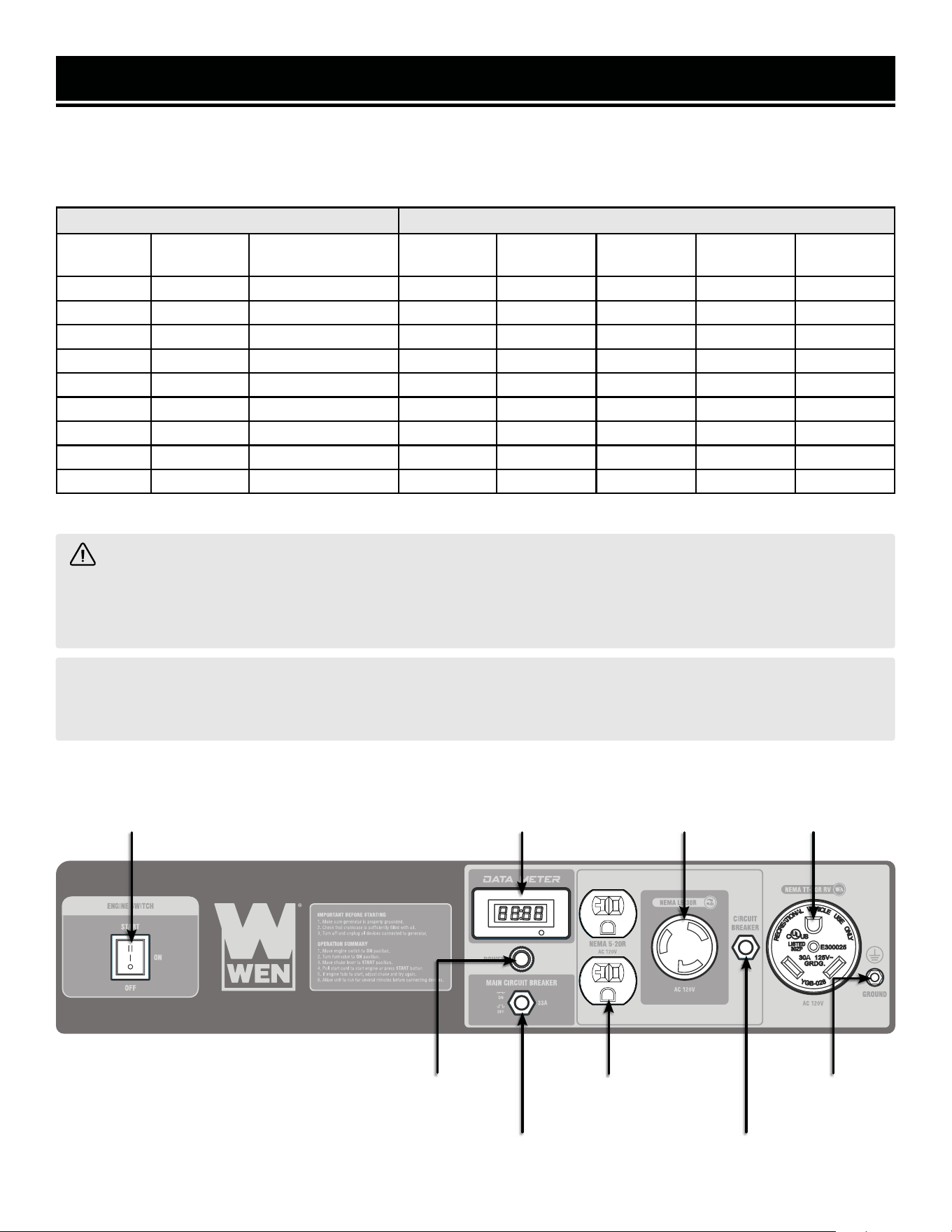
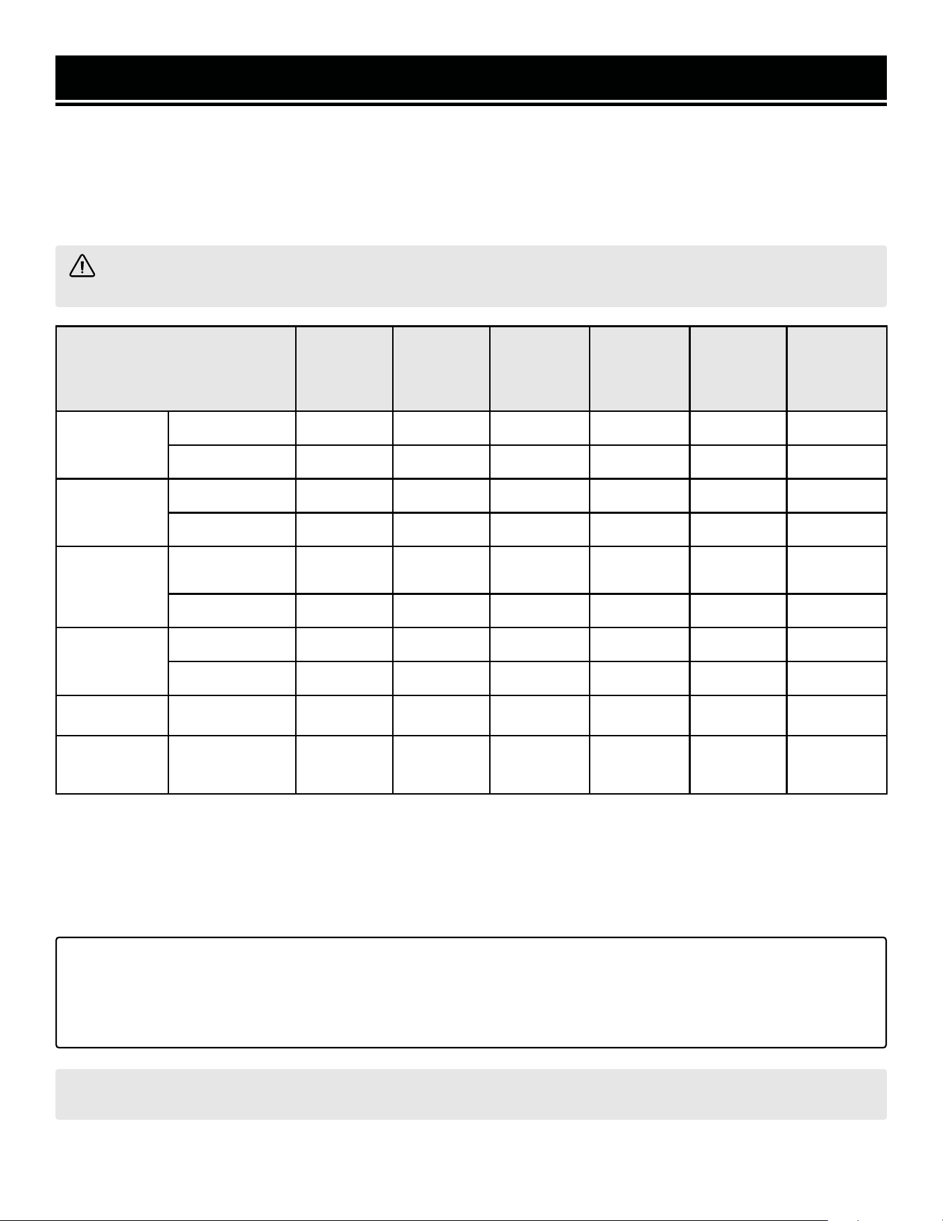
Table 3 - Power Cord Requirement Guide*NR = Not Recommended
Device Requirements Max. Cord Length (ft) by Wire Gauge
Amps Watts
(120V)
Watts (240V) #8 wire #10 wire #12 wire #14 wire #16 wire
2.5 300 600 NR NR NR 375 250
5 600 1200 NR NR 300 200 125
7.5 900 1800 NR 350 200 125 100
10 1200 2400 NR 250 150 100 50
15 1800 3600 NR 150 100 65 NR
20 2400 4800 175 125 75 50 NR
25 3000 6000 150 100 60 NR NR
30 3600 7200 125 65 NR NR NR
40 4800 9600 90 NR NR NR NR
WARNING! Generator should only be connected to electrical devices, either directly or with an extension
cord. NEVER CONNECT TO A BUILDING ELECTRICAL SYSTEM unless a qualified electrician has connected the
generator to a transfer switch as a separately derived system. Such connections must comply with local electri-
cal laws and codes. Failure to comply can create a back-feed, which may result in serious injury or death.
NOTE: For power outages, permanently installed, stationary generators are better suited for providing backup
power to your home. Even a properly connected portable generator can become overloaded. This may result in
overheating or stressing the machine’s components, possibly leading to generator failure.
SOME NOTES ABOUT POWER CORDS
Refer to the following chart in determining the necessary gauge extension cord for each of your devices. Round up
to the higher amperage in the chart to maximize safety.
USING THE GENERATOR
Electric Start Data Meter
120V, 20A
Receptacle
120V, 30A
Receptacle
20A Circuit
Breaker
120V, 30A RV
Receptacle
33A Circuit
Breaker
Grounding
Nut
Power
Indicator
22
WARNING! Never perform maintenance operations while the generator is running. Before maintaining or
servicing the generator, turn OFF the generator, disconnect all devices and allow the generator to cool down.
NOTE: Failure to properly maintain the generator will void the warranty.
RECOMMENDED MAINTENANCE SCHEDULE
Proper routine maintenance of the generator will help prolong the life of the machine. Please perform maintenance
checks and operations according to the maintenance schedule below, Table 4. If there are any questions about the
maintenance procedures listed in this manual, please contact customer service at 1-847-429-9263 (M-F 8-5 CST),
or email [email protected].
IMPORTANT GENERATOR MAINTENANCE TIPS:
• Drain your carburetor after each use and before storage to prevent it from clogging.
• Do not store the generator with fuel inside the tank for more than 2 months - the fuel will go bad.
• Run the generator for 20 to 30 minutes every month to maximize its lifespan.
Recommended
Maintenance Schedule
Every 8
Hours or
Daily
Every 25
Hours
Every 3
Months or
50 Hours
Every 6
Months or
100 Hours
Before
Storage
As
Necessary
Engine Oil
Check Level X
Replace X** X** X* X
Air Filter
Check X*
Clean X*
Spark Plug
Check/Clean/
Regap
X
Change X X
Fuel
Check Level X
Drain X X
Carburetor Drain X X
Spark
Arrestor
Check/Clean X
Table 4 - Recommended Maintenance Schedule* Clean/change more often under dusty conditions
or operating under heavy load.
** Change the oil after the first 8 hours of operation,
after the first 25 hours of operation, and every 50
hours after that.
MAINTENANCE
23
MAINTENANCE
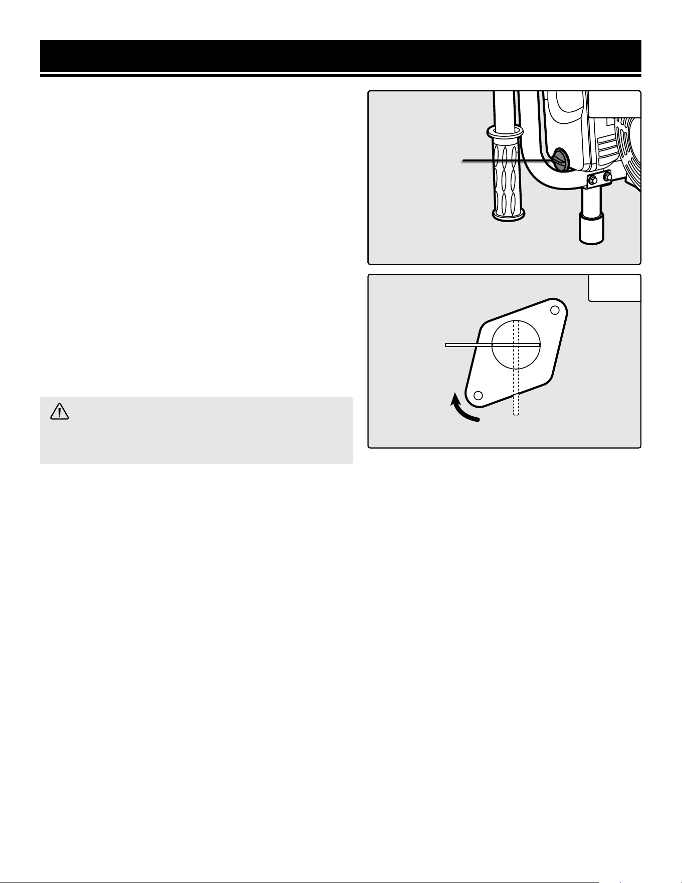
DRAINING THE CARBURETOR
Draining the carburetor is recommended after every use to
prevent the fuel from clogging up the carburetor. The car-
buretor can be accessed from the backside of the generator
between the engine and the air filter.
1. Turn the fuel valve to OFF position to prevent gasoline
from draining from the fuel tank.
2. Open up the carburetor drain plug (Fig. 12) with a screw-
driver and drain out any gasoline that has built up inside.
3. Once the fuel has drained, close the drain plug with the
screwdriver.
Carburetor Carburetor
Drain PlugDrain Plug
Carburetor
Drain Plug
NOTE: Make sure to drain your carburetor before storing the generator for long periods of time.
WARNING! To prevent serious injury from fire, follow the kit installation procedures in a well-ventilated
area away from ignition sources. If the engine is hot from use, shut the engine off and wait for it to cool before
proceeding. Do not smoke near the generator. Warranty will be void if adjustments are not made for high altitude
use.
CLEANING THE GENERATOR
Never clean the generator when it is running! Never clean with a bucket of water or a hose. Water can get inside the
working parts of the generator and cause corrosion or a short circuit.
Always try to use the generator in a cool, dry place. If the generator becomes dirty, clean the exterior with a damp
cloth, a soft brush, a vacuum or pressurized air.
CHECKING THE OIL
Check the oil level of the generator according to the Recommended Maintenance Schedule. The generator is equipped
with an automatic shutoff to protect it from running on low oil. The generator should be checked before each use
for proper oil level. This is a critical step for proper engine starting.
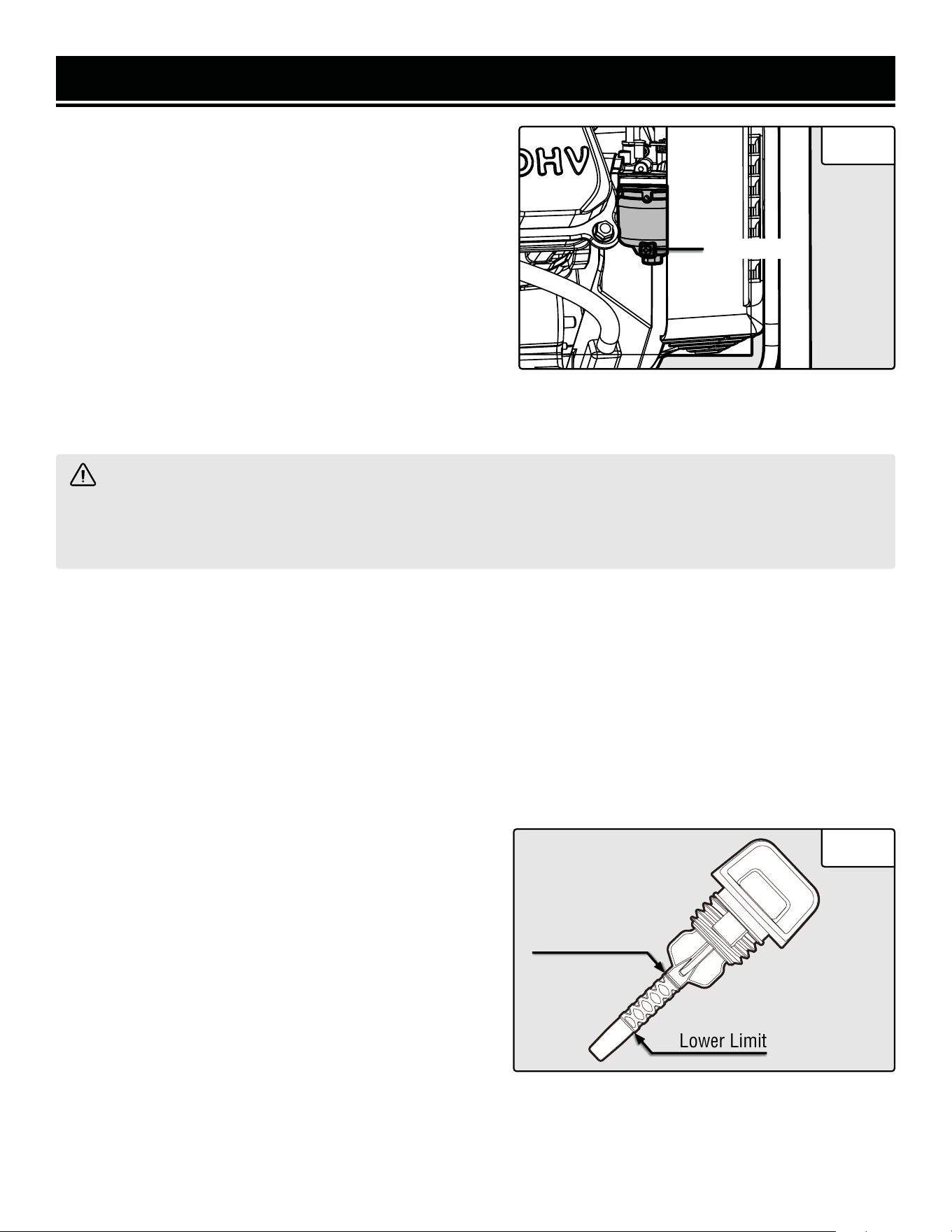
To check the oil level:
1. Make sure the generator is on a level surface.
Lower Limit
Upper Limit
2. Clean around oil fill. Remove dipstick and wipe the dip-
stick with a clean rag. Insert the dipstick into the oil fill
opening without screwing in. Remove the dipstick to check
the oil mark. Add oil if the oil mark covers less than one half
of the dipstick.
3. Slowly add more oil and repeat step 2 until the oil mark
reaches to the top of dipstick (Fig. 13). Do not over fill the
crankcase.
4. Reinstall oil dipstick.
Fig. 12
Fig. 13
24
NOTE: The WEN Magnetic Oil Dipstick (model 55201) is available for purchase on wenproducts.com. The dipstick’s
industrial-strength magnetic tip will collect metal shavings from your generator’s oil compartment to help preserve
the engine and extend your generator’s lifespan.
MAINTENANCE
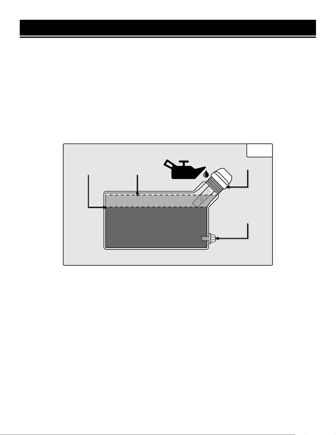
CHANGING / DRAINING THE OIL
Change the oil according to the Recommended Maintenance Schedule. Changing the oil when the engine is warm
allows for complete drainage. Change the oil more often if operating under heavy load or high ambient tempera-
tures. It is also necessary to drain the oil from the crankcase if it has become contaminated with water or dirt. The
oil capacity of the generator engine is 17 fluid ounces. Add oil when the oil level is low. For proper type and weight
of oil refer to “add oil” portion of the “Generator Preparation” section. Drain the oil from the generator according to
the following steps after removing the side panel.
1. Place a container underneath the engine to catch the oil as it drains.
2. Using a 10 mm hex wrench, unscrew the oil drain plug (Fig. 14). Allow the oil to drain from the engine.
3. Reinstall the oil drain plug and tighten with a 10 mm hex wrench.
TO REFILL THE OIL
1. Make sure the generator is on a level surface. Tilting the generator to assist in filling will cause oil to flow into
engine areas and will cause damage. Keep generator level!
2. Remove the dipstick from the engine.
3. Using a funnel or appropriate dispenser, add the correct amount of oil into the crankcase. The engine is equipped
with a low oil pressure sensor and will not start if the amount of oil is insufficient.
4. The oil is full when it reaches halfway up the threads of the dipstick (oil upper level fill line - Fig. 14). Reinstall
dipstick.
NOTE: Never dispose of used motor oil in the trash or down a drain. Please call a local recycling center or auto
garage to arrange oil disposal.
Oil Dipstick
Oil Drain Plug
Upper Level
Fill Line
Lower Level
Fill Line
Fig. 14
25
MAINTENANCE
AIR CLEANER MAINTENANCE
Routine maintenance of the air cleaner helps maintain prop-
er airflow to the carburetor. Occasionally check that the air
cleaner is free of excessive dirt. Refer to Recommended
Maintenance Schedule.
1. Unscrew the cover bolt (Fig. 15 - 1), then remove the air
cleaner cover.
2. Remove the air cleaner element from the casing (the
sponge-like filter inside).
3. Check and clean the spongy filter. Replace with a new
one if the element has been damaged. Good filters can be
washed in soapy water, dried and reused.
4. Wipe off excessive oil from the air cleaner case. Small
amounts of oil in the element is normal and necessary for
the engine to work properly.
5. Reinstall the air cleaner element and cover.
CAUTION! Running the engine with dirty, damaged
or missing air cleaner element will cause the engine to
wear out prematurely.
FUEL FILTER CUP CLEANING
The fuel filter cup is a small well underneath the fuel valve. It helps to trap dirt and water that may be in the fuel tank
before it can enter the engine. To clean the fuel filter cup:
1. Turn the fuel valve to the “OFF” position (Fig. 16).
2. Unscrew the fuel filter cup from the fuel valve using a wrench. Turn the valve towards you and unscrew it.
3. Clean the cup of all sediments using a rag or brush.
4. Reinstall the fuel filter cup.
To maximize the lifespan of this generator, make sure to run it at least once a month. If you do not run it often,
it will greatly shorten the lifespan and performace of the generator.
OFF
ON
Fig. 15
Fig. 16
1
26
MAINTENANCE
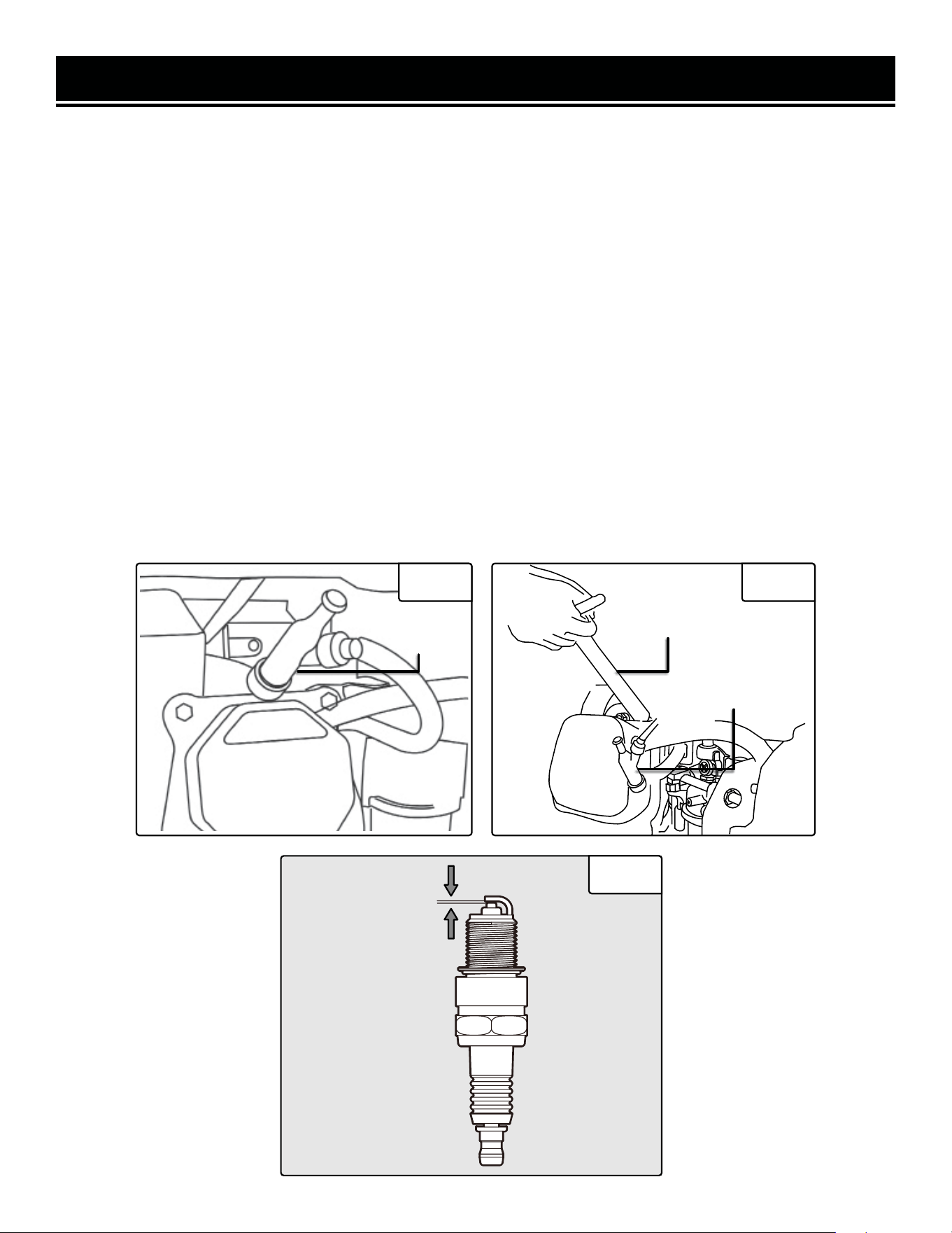
SPARK PLUG MAINTENANCE
Check the spark plug regularly for proper engine operation (refer to the Recommended Maintenance Schedule. A
good spark plug should be intact, free of deposits, and properly gapped.
To inspect the spark plug (Fig. 17 - 19):
1. Pull on the spark plug cap to remove it. Be careful not to tear insulation or wire.
2. Unscrew the spark plug from the engine using the spark plug wrench provided. There is limited space for the
wrench to turn. Use both rows of holes in the spark plug wrench to gain leverage and loosen the plug.
3. Visually inspect the spark plug for cracks or excessive electrode wear. Replace as necessary (Torch F6TC / NGK
BP6ES).
4. Measure the plug gap with a spark plug gap gauge. The gap should be 0.7 to 0.8 mm (0.028-0.031 in.) (Fig. 19).
5. If you are re-using the spark plug, use a wire brush to clean any dirt from around the spark plug base then re-gap
the spark plug.
6. Screw the spark plug back into the spark plug hole using the spark plug wrench. Do not over-tighten the spark
plug. Recommended tightening is ½ to ¾ of a turn after the spark plug gasket contacts spark plug hole, or 15 ft-lbs.
Reinstall the spark plug cap.
0.7 - 0.8mm
CylinderCylinder
AssemblyAssembly
Cylinder
Assembly
SparkSpark
PlugPlug
Spark
Plug
Plug
Wrench
Spark Plug
Cap
Fig. 17 Fig. 18
Fig. 19
27

MAINTENANCE
DRAINING THE FUEL TANK
Clean the fuel tank each year or before storing the generator for extended periods of time. To drain the fuel tank and
carburetor:
1. Turn the fuel valve to the “OFF” position.
2. Remove the fuel line between the fuel valve and carburetor.
CAUTION! A small amount of fuel may leak from the hose during removal.
3. Attach a fuel line (not included with the generator) to the exposed end of the fuel valve.
4. Position the fuel line into an appropriate container and open the fuel valve.
5. Once the fuel is drained, shut off the fuel valve.
6. Start and run the engine until the fuel runs out.
7. Remove the fuel filter cup (see Fuel Filter Cup Cleaning).
8. Empty the fuel filter cup of any fuel and clean.
9. Reinstall the fuel filter cup.
10. Store the emptied gasoline in a suitable place.
CAUTION! Do not store fuel for more than 3 months.
To maximize the lifespan of this generator, make sure to run it at least once a month. If you do not run it often,
it will greatly shorten the lifespan and performace of the generator.
STORAGE & TRANSPORT
If the generator is being stored for short periods of time (30 to 60 days), add stabilized fuel to the fuel tank until full.
NOTE: Filling the tank reduces the amount of air in the tank and helps reduce deterioration of fuel. Run the engine
for 2 – 3 minutes allowing stabilized fuel mixture to circulate through the carburetor.
When storing the generator for extended periods of time:
• Drain the fuel tank (see Draining the Fuel Tank).
• Change oil.
• Do not obstruct any ventilation openings.
• Keep the generator in a cool dry area.
• Disconnect the battery quick-connector (see p. 16).
When transporting generator:
• Tighten fuel cap and vacuum relief valve. Drain the fuel tank if possible (see Draining the Fuel Tank).
• Keep the generator upright. Never place the generator side down. Doing so will make it difficult to start.
CAUTION! Never place any type of storage cover on the generator while it is still hot.
28
WARNING! Stop using the generator immediately if any of the following problems occur or risk serious
personal injury. If you have any questions, please contact customer service at 1-847-429-9263 (M-F 8-5 CST),
or email [email protected].
TROUBLESHOOTING GUIDE
PROBLEM POSSIBLE CAUSE SOLUTION
Engine will not start.
Engine switch is set to OFF. Set engine switch to ON.
Fuel valve is turned to OFF. Turn fuel valve to ON.
Choke is open. Close the choke.
Engine is out of fuel. Add fuel.
Engine is filled with contami-
nated or old fuel.
Drain the fuel in the tank. Fill with fresh fuel.
Spark plug is dirty. Clean the spark plug.
Spark plug is broken. Replace spark plug.
Oil level is low.
Add or replace oil. This generator is equipped with a low oil
sensor. The engine will not start unless the oil level is suf-
ficient.
Carburetor is air locked.
Shut off the fuel valve. Remove the nut from the bottom of the
carburetor. Take off the carburetor to allow it to reset. Place
the carburetor back and reinstall the nut.
Engine runs but
there is no
electrical output.
Circuit breaker has been
tripped due to overload.
Disconnect all the loads. Wait for two minutes and push the
circuit breaker to the ON position to reset it.
Bad connecting cords/wires.
Check the power cords and extension cords. Do not use if any
cord is damaged. Replace damaged cords immediately.
Bad electrical device con-
nected to the generator.
Try connecting a different device.
Generator runs but
does not support all
electrical devices
connected.
Generator is overloaded.
Perform these steps:
1. Turn off all electrical devices.
2. Unplug all electrical devices.
3. Turn off generator.
4. Wait several minutes.
5. Restart generator.
6. Try connecting few electrical loads to the generator.
Short circuit in one of the
devices.
Try disconnecting any faulty or short-circuited electrical loads.
The air filter is dirty. Clean or replace the air filter element (see page 20).
Engine is
“Hunting” during
Operation (Engine
RPM is fluctuating).
1. The fuel isn’t running
through the fuel valve.
2. The air filter is clogged.
3. The muffler or spark ar-
rester is blocked
4. There is gunk in the carbu-
retor preventing the fuel/air to
be consistent.
Turn off the generator and wait for it to cool down. Perform
the following steps:
1. Check if the fuel is properly and consistently going through
the fuel valve
2. Check for any blockage in the air filter. Check and clean the
air filter as necessary.
3. Check if the spark arrester is blocked. Clean with metal
brush as necessary.
4. Use “Gunk remover” spray on the carburator jets.
29
EXPLODED VIEW & PARTS LIST
NOTE: Replacement parts can be purchased from wenproducts.com, or by calling our customer service at
1-847-429-9263, M-F 8-5 CST. Parts and accessories that wear down over the course of normal use are not
covered by the two-year warranty. Not all parts may be available for purchase.
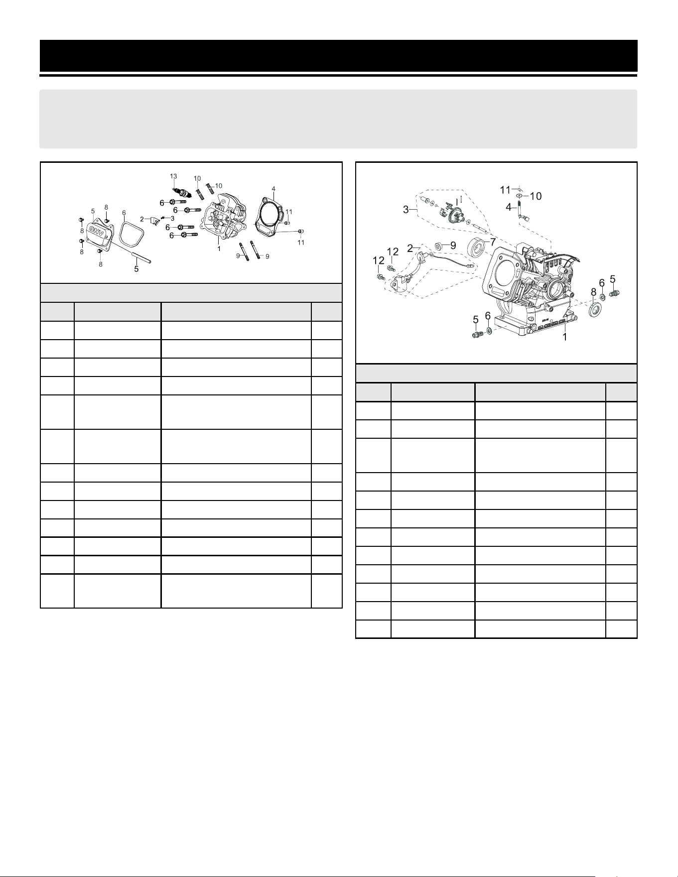
Fig. 1 - Cylinder Head Assembly
No. Part Description Qty.
1-1 GN5000-0101 Cylinder Head Assembly 1
1-2 GN5000-0102 Cylinder Head limit plate 1
1-3 GN5000-0103 Bolt, M6x10 1
1-4 GN5000-0104 Cylinder Head Gasket 1
1-5 GN5000-0105
Cylinder Head Cover
Assembly
1
1-6 GN5000-0106
Cylinder Head Cover
Gasket
1
1-7 GN5000-0107 Breather Tube 1
1-8 P54040 Bolt, M6x12 4
1-9 P54047 Stud 2
1-10 P54058 Stud 2
1-11 P54048 Pin 2
1-12 P54062 Bolt, M8x60 4
1-13 P54060
Spark Plug, Torch F6TC
(NGK BP6ES)
1
Fig. 2 - Crankcase Assembly
No. Part Description Qty.
2-1 GN5000-0201 Crankcase 1
2-2 P54020 Oil Sensor 1
2-3 GN5000-0203
Regular Gear
Assembly
1
2-4 GN5000-0204 Governor Arm 1
2-5 P54000 Oil Drain Plug 1
2-6 GN5000-0206 Washer 1
2-7 GN5000-0207 Bearing, 6205 1
2-8 P54008 Oil Seal 2
2-9 P54003 Nut, M10 1
2-10 GN5000-0210 Washer 2
2-11 P54018 Pin 1
2-12 P54024 Bolt, M6x14 1
30
EXPLODED VIEW & PARTS LIST
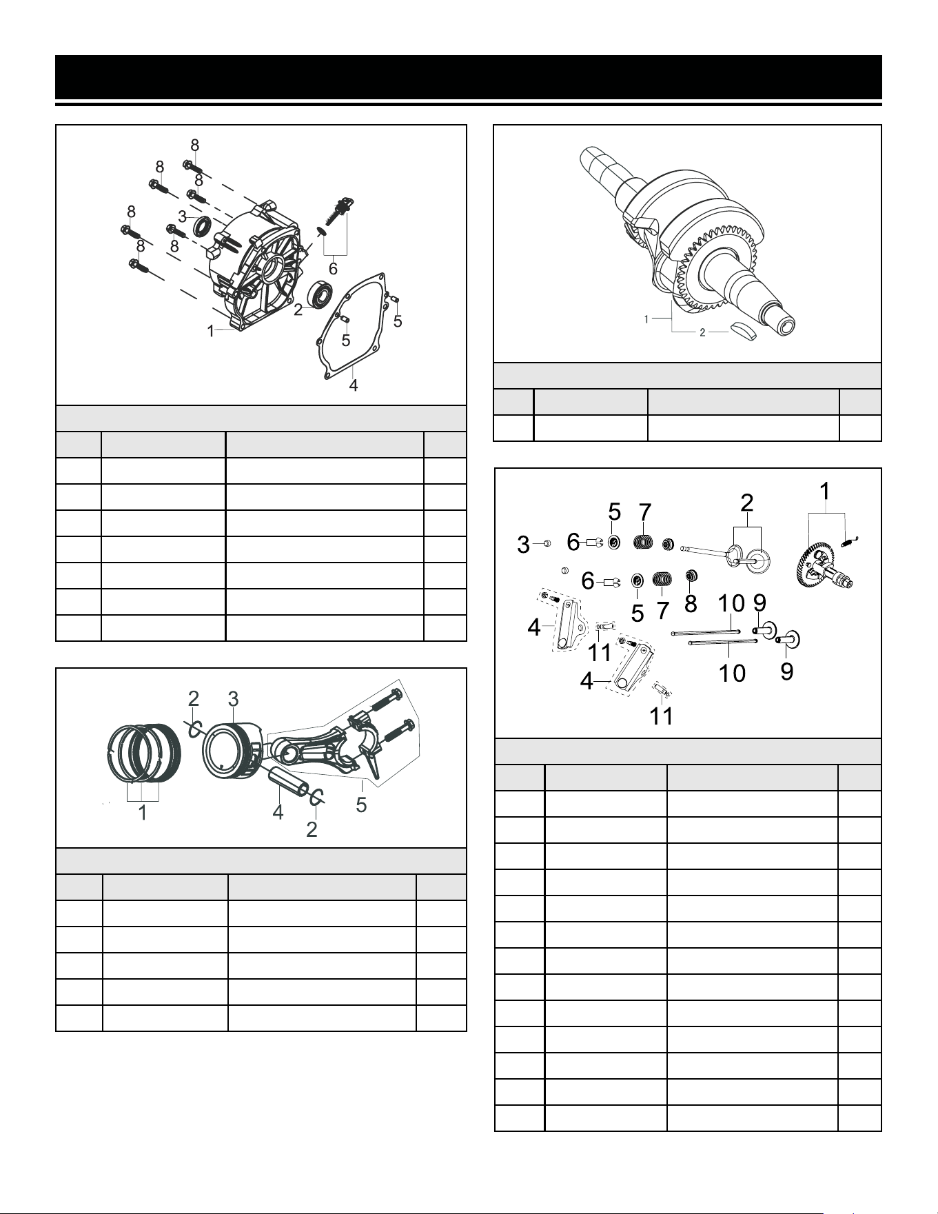
Fig. 3 - Crankcase Cover Assembly
No. Part Description Qty.
3-1 P54075 Crankcase Cover 1
3-2 GN5000-0207 Bearing, 6205 1
3-3 P54088 Oil Seal 1
3-4 P54080 Crankcase Gasket 1
3-5 P54082 Pin 2
3-6 P54086 Oil Dipstick Assembly 1
3-8 P54092 Bolt, M8x32 6
Fig. 4 - Crankshaft
No. Part Description Qty.
4-1 GN5000-0401 Crankshaft Assembly 1
Fig. 5 - Piston Ring / Connecting Rod
No. Part Description Qty.
5-1 GN5000-0501 Piston Ring Assembly 1
5-2 GN5000-0502 Piston Pin Clip 2
5-3 GN5000-0503 Piston 1
5-4 GN5000-0504 Piston Pin 1
5-5 GN5000-0505 Connecting Rod 1
Fig. 6 - Valve / Camshaft Assembly
No. Part Description Qty.
6-1 GN5000-0601 Camshaft Assembly 1
6-2 GN5000-0602 Valve 2
6-3 GN5000-0603 Valve Adjustment Cap 2
6-4 GN5000-0613 Valve Rocker 2
6-5 P54158 Valve Spring Seat 2
6-6 P54160 Valve Lock 2
6-7 P54154 Valve Spring 2
6-8 P54161 Guide Seal 2
6-9 P54142 Tappet 2
6-10 GN5000-0610 Lifter 2
6-12 GN5000-0612 Rocker Shaft 2
6-14 P54130 Sleeve 2
6-15 P54128 Lock Nut 2
31
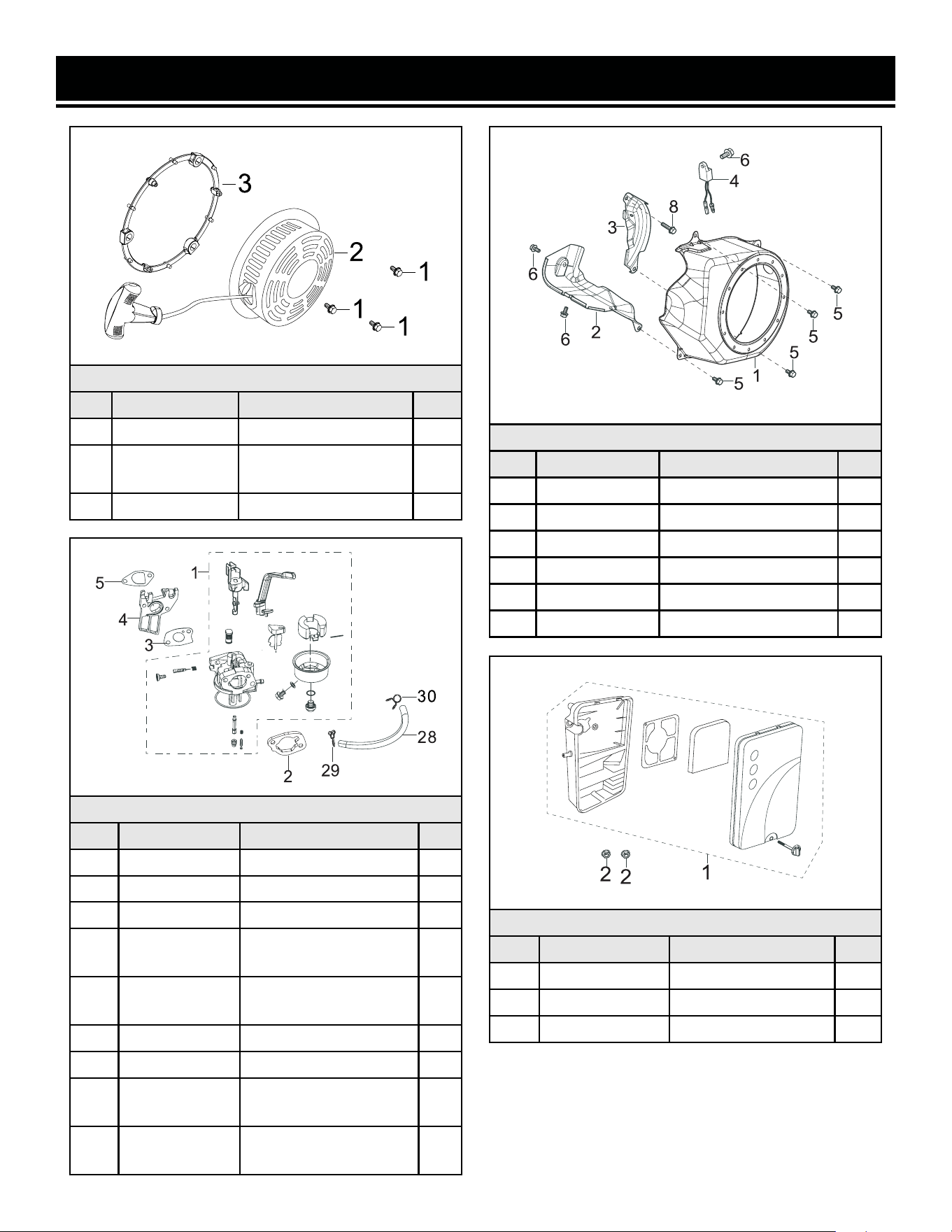
EXPLODED VIEW & PARTS LIST
Fig. 7 - Recoil Starter
No. Part Description Qty.
7-1 P54598 Bolt, M6x8 3
7-2 GN5000-0702
Recoil Starter
Assembly
1
7-3 GN5000-0703 Retaining Ring 1
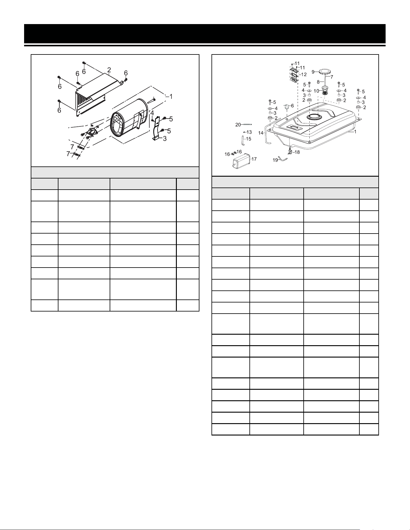
Fig. 8 - Shroud
No. Part Description Qty.
8-1 GN5000-0801 Shroud End 1
8-2 GN5000-0802 Shroud Cylinder Body 1
8-3 P54596B Lower Shield 1
8-4 GN5000-804 Bolt M6x16 1
8-5 P54040 Bolt, M6x12 4
8-6 P54040 Bolt, M6x10 2
Fig. 9 - Carburetor Assembly
No. Part Description Qty.
9-1 GN5000-0901 Carburetor Assembly 1
9-2 P54168 Air Filter Gasket 1
9-3 P54166 Carburetor Gasket 1
9-4 GN5000-0904
Carburetor Insulator
Plate
1
9-5 GN5000-0905
Carburetor Insulator
Gasket
1
9-28 P54388 Fuel Line 1
9-29 P54390 Hose Clamp 2
N.P. GN5000-HA36
High-Altitude Kit,
3000 - 6000 ft
N/A
N.P. GN5000-HA68
High-Altitude Kit,
6000 - 8000 ft
N/A
Fig. 10 - Air Cleaner
No. Part Description Qty.
10-1 GN5000-1001 Air Filter Assembly 1
N.P. GN5000-1001.1 Air Filter Element 1
10-2 P54179 Nut, M6 2
32
EXPLODED VIEW & PARTS LIST
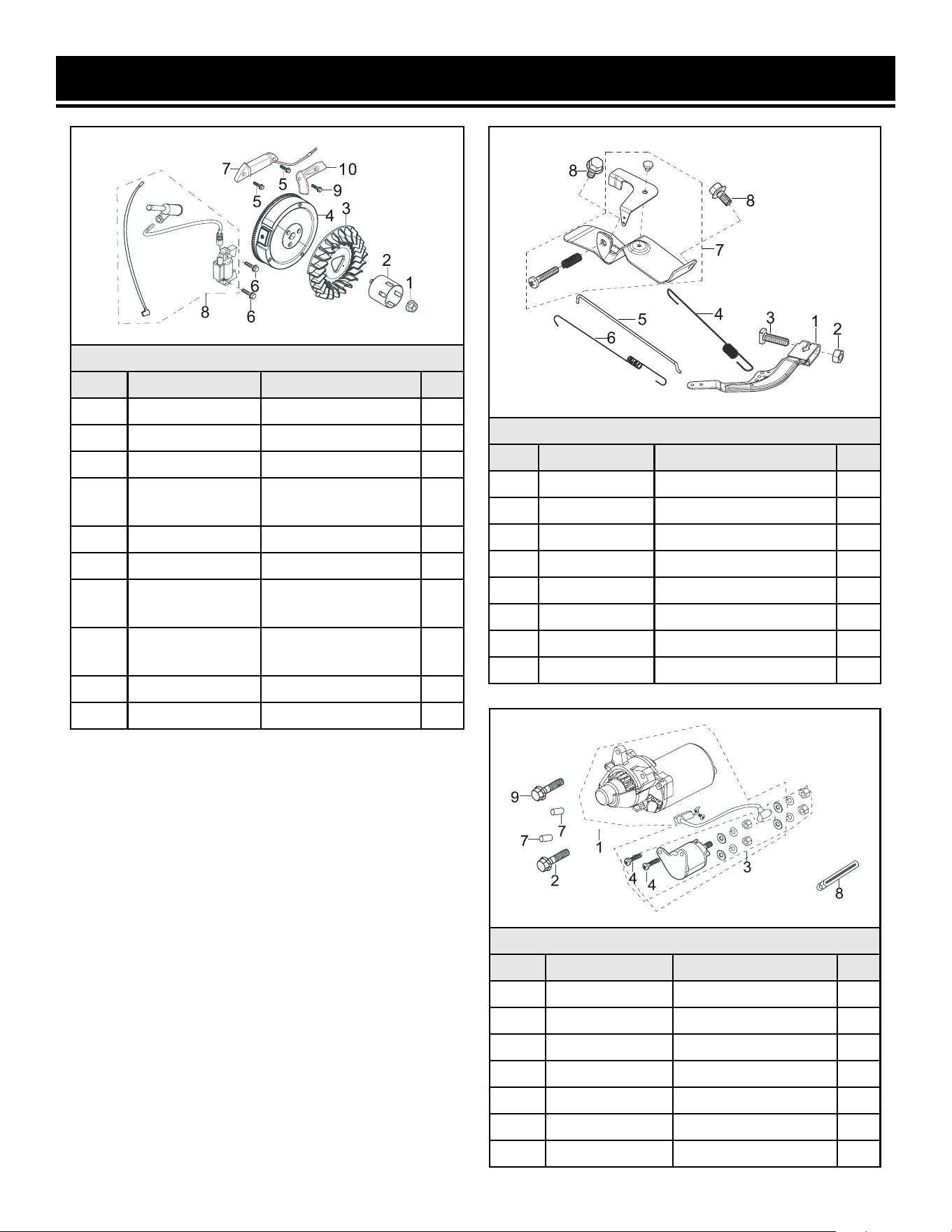
Fig. 11 - Flywheel / Ignition Coil
No. Part Description Qty.
11-1 P54630 Nut, M14-1.5 1
11-2 GN5000-1102 Starting Flange 1
11-3 GN5000-1103 Flywheel Fan 1
11-4 GN5000-1104
Flywheel
Subassembly
1
11-5 56475-1105 Bolt, M6x25 2
11-6 P54628 Bolt, M6x28 2
11-7 56475-1107
Charge Coil
Subassembly
1
11-8 P54638
Ignition Coil
Assembly
1
11-9 56475-1109 Bolt, M6x10 1
11-10 56475-1110 Coil Clamp 1
Fig. 12 - Control Assembly
No. Part Description Qty.
12-1 P54624 Regulating Arm 1
12-2 P54176 Nut, M6 1
12-3 P54622 Lock Bolt, M6x21 1
12-4 P54616 Back Spring 1
12-5 GN5000-1205 Pulling Rod 1
12-6 P54618 Regulating Spring 1
12-7 GN5000-1207 Regulating Assembly 1
12-8 P54619 Bolt, M6x10 2
Fig. 13 - Starter Assembly
No. Part Description Qty.
13-1 GN5000-1301 Starter Motor 1
13-2 56475-1302 Bolt, M6x35 1
13-3 56475-1303 Starter Solenoid 1
13-4 56475-1304 Bolt,M5x14 2
13-7 56475-1305 Pin 2
13-8 56475-1306 Clip 5
13-9 56475-1307 Bolt, M6x25 1
33
EXPLODED VIEW & PARTS LIST
Fig. 14 - Muffler Assembly
No. Part Description Qty.
14-1 GN5000-1401 Muffler Assembly 1
N.P.
GN5000-
1401.1
Spark Arrestor 1
14-2 P54402 Muffler Cover 1
14-3 P54412 Muffler Bracket 1
14-4 P54422 Bolt, M6x12 1
14-5 P54404 Bolt, M8x16 2
14-6 P54422 Bolt, M6x12 5
14-7 P54426
Gasket, Exhaust
Outlet
1
14-10 P54246 Nut, M8 2
Fig. 15 - Tank, Fuel
No. Part Description Qty.
15-1 56475VN-1501 Fuel Tank 1
15-2 P54386 Cushion 4
15-3 P54396 Bushing 4
15-4 P54384 Washer 4
15-5 P54186 Bolt, M6x25 4
15-6 P54375-2 Valve 1
15-7 P54373-1 Clip 1
15-8 P54373 Chain 1
15-9 P54365 Fuel Cap 1
15-10 P54372 Fuel Filter 1
15-11, 12 P54374
Fuel Gauge
Assembly
2
15-13 P54375-9 Clamp 1
15-14 56475-1518 Rubber Hose 1
15-15 56475-1524
Carbon Tank
Hose
1
15-16 56475-1526 Bolt, M6x12 2
15-17 56475-1525 Carbon tank
15-18 56475VN-1518 Fuel Valve 1
15-19 P54388 Fuel Tube 1
15-20 5647-1519 Clip 1
34
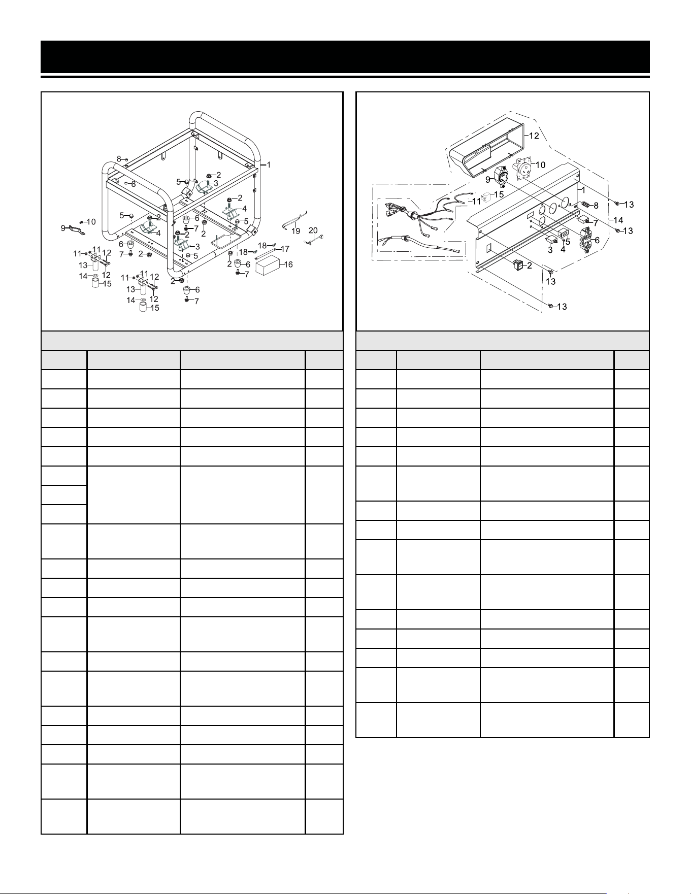
EXPLODED VIEW & PARTS LIST
Fig. 16 - Frame, Engine
No. Part Description Qty.
16-1 GN5000-1601 Frame Comp 1
16-2 P54246 Nut, M8 2
16-3 P54242 Bottom Rubber A 2
16-4 P54244 Bottom Rubber B 2
16-5 P54246 Nut, M8 4
16-6
P54871
Rubber Foot
Assembly
416-7
16-8
16-9 56475-1720
Air Filter Support
Bracket
1
16-10 56475-1711 Bolt, M6x12 1
16-11 56475-1712 Nut, M6 4
16-12 56475-1711 Bolt, M6x40 4
16-13 56475-1706
Front Rubber Foot
Assembly
2
16-14 56475-1710 Washer 2
16-15 P54871-3
Front Rubber Foot
Sleeve
2
16-16 56475-1713 12V Battery 1
16-17 56475-1715 Battery Clamp 1
16-18 56475-1714 Butterfly nut 2
16-19 GN5000-1619
Quick-connector
Wiring, Motor
1
16-20 GN5000-1620
Quick-connector
Wiring, Battery
1
Fig. 17 - Panel Subassembly, Control
No. Part Description Qty.
17-1 P54283C Control Panel 1
17-2 P54296B Ignition Switch 1
17-3 GN5000-1707 33A Circuit Breaker 1
17-4 56475-1804 Power Indicator 1
17-5 P54877 Hour Meter 1
17-6 P54454
20A 5-20R Duplex
Receptacle
1
17-7 56475-1803 20A Circuit Breaker 1
17-8 P54262 Grounding Terminal 1
17-9 P54272B
30A L5-30R
Receptacle
1
17-10 56475-1810
30A TT-30R RV
Receptacle
1
17-11 56475-1811 Wiring Harness 1
17-12 56475-1812 Rear Panel 1
17-13 P54304 Bolt, M6x12 4
17-14
GN5000-
1714ASM
Control Panel
Assembly
1
17-15 GN5000-1715
Low-Speed / Low-Oil
Sensor
1
35

EXPLODED VIEW & PARTS LIST
NOTE: Replacement parts can be purchased from wenproducts.com, or by calling our customer service at
1-847-429-9263, M-F 8-5 CST. Parts and accessories that wear down over the course of normal use are not
covered by the two-year warranty. Not all parts may be available for purchase.
Fig. 18 - Rotor / Stator
No. Part Description Qty.
18-1 GN5000-1801
Alternator
Assembly
1
18-2 GN5000-1802 Alternator Bracket 1
18-3 GN5000-1803 Rotor 1
18-4 GN5000-1804 Stator 1
18-5 GN5000-1805 Bolt, M6x174 4
18-6 GN5000-1806
Rotor Bolt,
M8x230
1
18-7 P54348 Washer 1
18-8 56475-1908 Voltage Regulator 1
18-9 P54360 Bolt, M5x12 2
18-10 56475-1910 Cable Tie 2
18-11 GN5000-1811 End Cover 1
18-12 P54340 Bolt, M5x12 2
18-13 56475-1913 Stopper 1
18-14 56475-1914 Bolt, M6x12 1
18-15 56475-1915 Terminal 1
18-16 P54332
Carbon Brush
Subassembly
1
Fig. 19 - Wheel Kit Assembly
No. Part Description Qty.
19-1 56475-1601 Wheel 2
19-2 56475-1602 Wheel Shaft 2
19-3 56475-1603 Nut, M12×1.75 2
19-4 56475-1604 Washer,1.5mm 2
19-5 56475-1605 Washer, 2.5mm 2
19-6 56475-1606 Nut, M12×1.75 2
Fig. 20 - Handles
No. Part Description Qty.
20-1 56475-2001 Rubber Seat 2
20-2 56475-2002 Bolt, M8x45 2
20-3 56475-2003 Nut, M6 2
20-4 56475-2004 Steel Handle 2
20-5 56475-2005
Rubber Handle
Sleeve
2
36
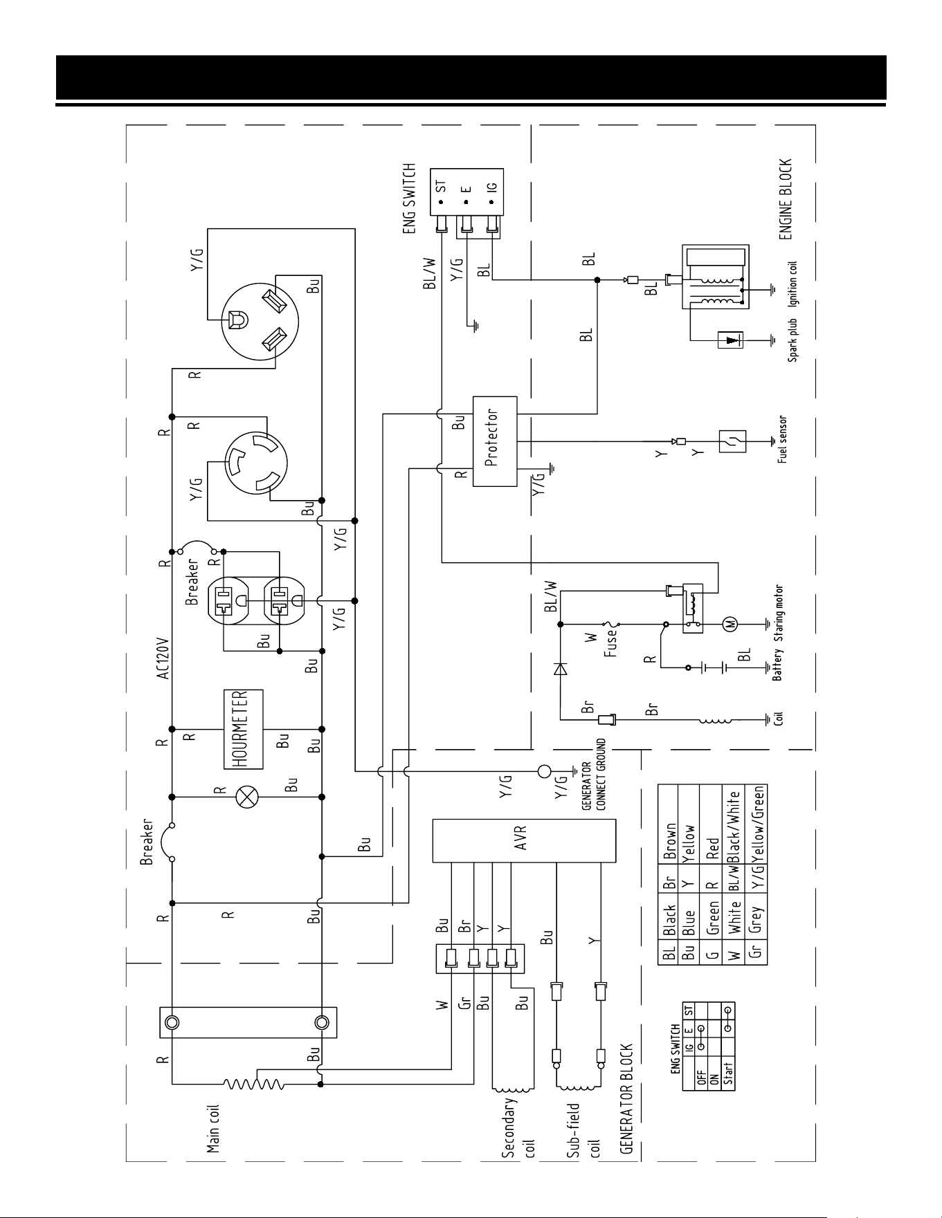
WIRING DIAGRAM
37

WARRANTY STATEMENT
38
WEN Products is committed to building tools that are dependable for years. Our warranties are consistent with this
commitment and our dedication to qualit
y.
LIMITED WARRANTY OF WEN PRODUCTS FOR HOME USE
GRE
AT LAKES TECHNOLOGIES, LLC (“Seller”) warrants to the original purchaser only, that all WEN
consumer
power tools will be free from defects in material or workmanship during personal use for a period of two (2) years
used
for professional or commercial use. Purchaser has 30 days from the date of purchase to report missing or
damaged parts.
SELLER’S
SOLE OBLIGATION AND YOUR EXCLUSIVE REMEDY under this Limited Warranty and, to the extent per-
mitted
by law, any warranty or condition implied by law, shall be the replacement of parts, without charge, which a
re
defective
in material or workmanship and which have not been subjected to misuse, alteration, careless handling,
misrepair
, abuse, neglect, normal wear and tear,
improper maintenance, or other conditions adversely affecting the
Product
or the component of the Product, whether by accident or intentionally, by persons other than Seller. To
make
a claim under this Limited Warranty, you must make sure to keep a copy of your proof of purchase that
clearly
-
dor
of Great Lakes Technologies, LLC. Purchasing through third party vendors, including but not limited to garage
sales,
pawn shops, resale shops, or any other secondhand merchant, voids the warranty included with this
product.
Contact [email protected] or 1-847-429-9263 with the following information to make arrangements:
your
shipping address, phone number, serial number, required part numbers, and proof of purchase. Damaged
or
defective parts and products may need to be sent to WEN before the replacements can be shipped out.
-
turning
a product for warranty service, the shipping charges must be prepaid by the purchaser. The product
must
be
shipped in its original container (or an equivalent), properly packed to withstand the hazards of shipment. The
product
must be fully insured with a copy of the proof of purchase enclosed. There must also be a description of
the
will be returned and shipped back to the pur
chaser at no charge for addresses within the contiguous United States.
THIS
LIMITED WARRANTY DOES NOT APPLY TO ITEMS THAT WEAR OUT FROM REGULAR USAGE OVER TIME,
INCLUDING
BELTS, BRUSHES, BLADES, BATTERIES, ETC. ANY IMPLIED WARRANTIES SHALL BE LIMITED IN
DUR
ATION TO TWO (2) YEARS FROM DATE OF PURCHASE. SOME STATES IN THE U.S. AND SOME CANADIAN
PROVINCES
DO NOT ALLOW LIMITATIONS ON HOW LONG AN IMPLIED WARRANTY LASTS, SO THE ABOVE LIMI-
TAT
ION MAY NOT APPLY TO YOU.
IN
NO EVENT SHALL SELLER BE LIABLE FOR ANY INCIDENTAL OR CONSEQUENTIAL DAMAGES (INCLUDING
BUT
NOT LIMITED TO LIABILITY FOR LOSS OF PROFITS) ARISING FROM THE SALE OR USE OF THIS PRODUCT.
SOME ST
ATES IN THE U.S. AND SOME CANADIAN PROVINCES DO NOT ALLOW THE EXCLUSION OR LIMITAT
ION
OF
INCIDENTAL OR CONSEQUENTIAL DAMAGES, SO THE ABOVE LIMITATION OR EXCLUSION MAY NOT APPLY
TO YOU.
THIS
LIMITED WARRANTY GIVES YOU SPECIFIC LEGAL RIGHTS, AND YOU MAY ALSO HAVE OTHER RIGHTS
WHICH
VARY FROM STATE TO STATE IN THE U.S., PROVINCE TO PROVINCE IN CANADA AND FROM COUNTRY
TO COUNT
RY.
THIS
LIMITED WARRANTY APPLIES ONLY TO ITEMS SOLD WITHIN THE UNITED STATES OF AMERICA, CANA-
DA
AND THE COMMONWEALTH OF PUERTO RICO. FOR WARRANTY COVERAGE WITHIN OTHER
COUNTRIES,
CONT
ACT THE WEN CUSTOMER SUPPORT LINE. FOR WARRANTY PARTS OR PRODUCTS REPAIRED UNDER
W
ARRANTY SHIPPING TO ADDRESSES OUTSIDE OF THE CONTIGUOUS UNITED STATES, ADDITIONAL
SHIPPING
CHARGES MAY APPLY.

NOTES
39

V. 2022.12.09
THANKS FOR
REMEMBERING