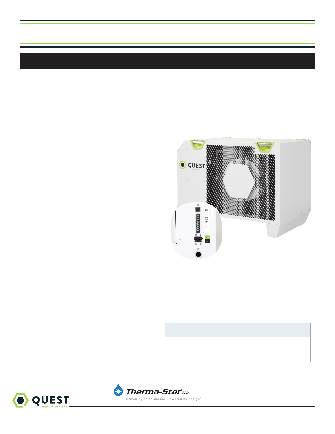
Quest 215 Dual
Quest Dry
Quest 876
Installation, Operation and Maintenance Instructions
This manual is provided to acquaint you with the
dehumidifier so that installation, operation and
maintenance can proceed successfully. Ultimate
satisfaction depends on the quality of installation and a
thorough understanding of this equipment. The dehumidifier
is built around tested engineering principles and has passed
a thorough inspection for quality of workmanship and
function.
Installation, Operation and Maintenance Instructions
4201 Lien Rd
Madison, WI 53704 Toll-Free 1-877-420-1330
www.QuestClimate.com info@QuestClimate.com
– Read and Save These Instructions –
Specifications subject to change without notice.
1
Features:
• Industry-leading efficiency
• Patented, refrigeration system
• High-efficiency, long-life impeller fan
• Quiet operation
• Superior air filtration (MERV-13 standard)
• Auto-restart after power outages
• Environmentally friendly R410A refrigerant
• Low voltage control
TS-1118
04/19 Rev. A
Water Removal Rates (Pints/Day) @ 80°F 60% (AHAM)
Dehumidifier Pints Removed Gallons/Liters
Quest 876 876 109.5/415.2
US Patent #10,168,058
Patent Pending
#7194870
#7246503

1-877-420-1330
Quest 876 Installation, Operation and Maintenance Instructions
2
www.QuestClimate.com
Table of Contents
Safety Precautions .................................................................... 3
1. Intended Application .............................................................4
2. Registrations ........................................................................4
3. Specifications .......................................................................4
4. Installation ........................................................................ 5
4.1 Location ........................................................................ 5
4.2 Electrical Requirements ............................................... 5
4.3 Condensate Removal ...................................................6
4.4 Hanging ........................................................................6
5. Control Options .................................................................... 7
5.1 Humidity Control .......................................................... 7
5.2 24VAC Wiring .............................................................. 7
5.2A Deh 3000R ......................................................8
5.2B Honeywell Remote Humidistat .......................8
5.2C Daisy Chain .......................................................8
6. Maintenance ........................................................................ 9
6.1 Standard Air Filter ......................................................... 9
7. Service ........................................................................ 9
7.1 Warranty ........................................................................ 9
7.2 Technical description ..................................................... 9
8. Ducting Guidelines ............................................................. 10
Wiring Diagram.................................................................. 10
9. Display ...................................................................... 10
9.1 User Interface .............................................................. 10
9.2 Settings Change Example ............................................11
9.3 Viewing Active Alarms/Alarm Logs ...........................12
9.4 Viewing Unit Run Hours ............................................. 13
Wiring Diagram ...................................................................... 14
Service Parts List .....................................................................15
Optional Parts List ..................................................................15
Warranty .......................................................................16

1-877-420-1330
Quest 876 Installation, Operation and Maintenance Instructions
3
www.QuestClimate.com
Safety Precautions
Read the installation, operation and maintenance instructions carefully before installing and operating this device. Proper
adherence to these instructions is essential to obtain maximum benefit from your Quest 876 Dehumidifier.
READ AND SAVE THESE INSTRUCTIONS
• The device is designed to be installed INDOORS IN A SPACE THAT IS
PROTECTED FROM RAIN AND FLOODING.
• Install the unit with space to access side panels for maintenance and
service. DO NOT INSTALL UNIT WITH THE SERVICE PANELS
INACCESSIBLE.
• Avoid directing the discharge air at people, or over the water in pool areas.
• If used near a pool, spa or water; be certain there is NO chance the unit
could fall into the water, be splashed and that it is plugged into an outlet
that is a GROUND FAULT INTERRUPT protected circuit.
• DO NOT use the device as a bench or table.
• DO NOT place the device directly on structural members. Provide
vibration isolation in order to minimize operational vibration and/or noise.
• A drain pan MUST be placed under the unit if installed above a living area
or above an area where water leakage could cause damage
• Make all electrical connections in accordance with the current edition of
the NEC ANSI/NFPA 70 and any national and local codes or ordinances
that may apply.
• Do not obstruct the air intake and exhaust. Maintain a 4ft clearance
around the air intake and exhaust.
• This appliance is not intended for use by persons (including children) with
reduced physical, sensory or mental capabilities, or lack of experience
and knowledge, unless they have been given supervision or instruction
concerning use of the appliance by a person responsible for their safety.
Children should be supervised to ensure that they do not play with the
appliance.
• Not intended for use at altitudes over 2000m.
1-877-420-1330
Quest 876 Installation, Operation and Maintenance Instructions
4
www.QuestClimate.com
1. Intended Application for Quest 876 Dehumidifier
The Quest 876 Dehumidifier is designed to operate in temperatures between 56° and 110°F.
In order to eciently control humidity levels, the area in which the dehumidifier is to be operated must be free of water
intrusion or excessive fresh (outside) air infiltration. Before installing the Quest 876 Dehumidifier, water intrusion and air
infiltration problems should be addressed or noted in calculations.
2. Registrations
The Quest 876 Dehumidifier units conform to unified standards: UL 60335-2-40, CSA 22.2 # 60335-2-40:2012 Ed.
1+4.
US Patent #10,168,058
Patent Pending #7194870
#7246503
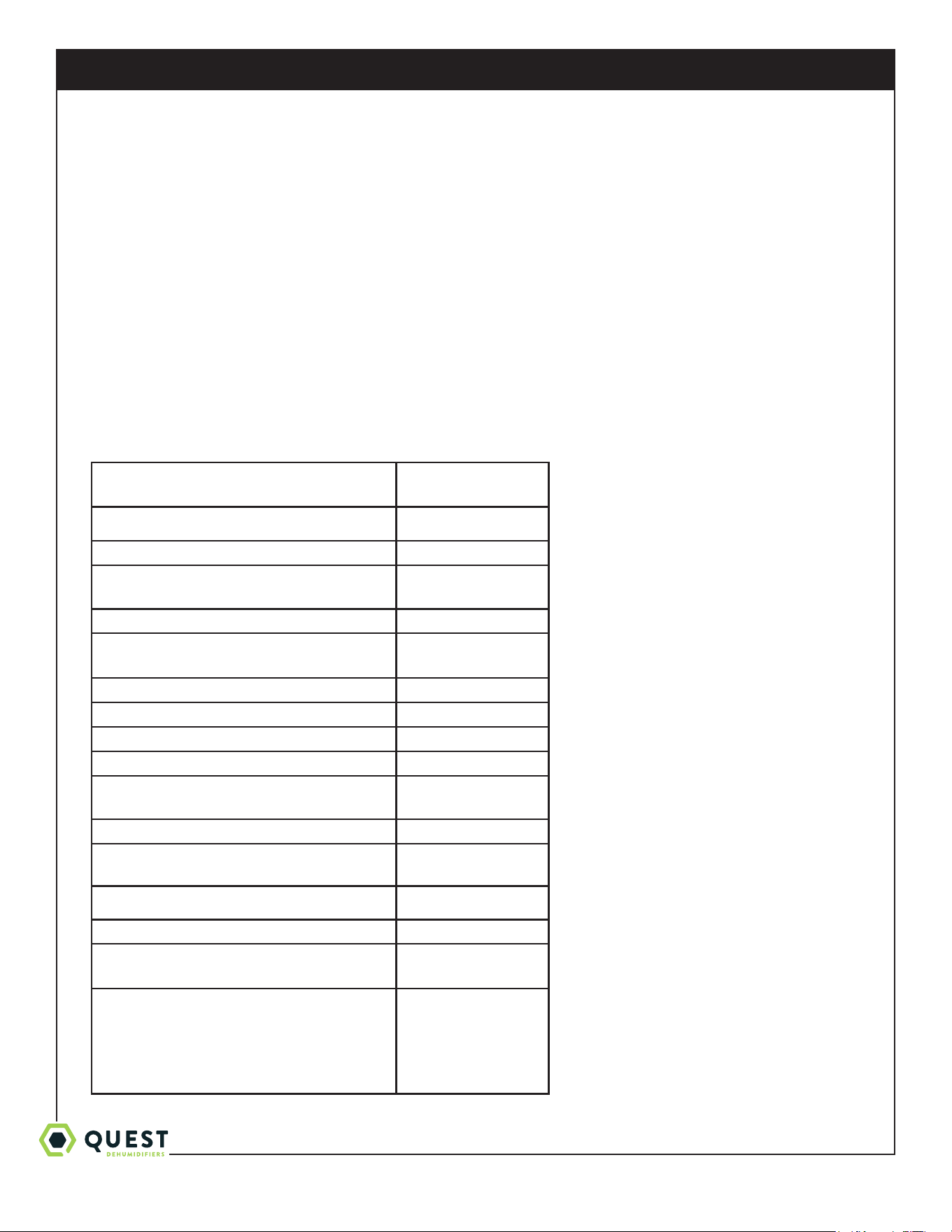
3. Specifications @ 80°F/60% RH
Unit: Quest 876
4037600
CFM
Power (Watts):
5500
Supply voltage:
220-240 VAC -
1 Phase - 60 Hz.
Current Draw (Amps):
24.7
Rated Current Draw (Amps):
(104°F 36%)
31.5
Minimum Circuit Ampacity (MCA):
42.5A
Maximum Overcurrent Protection (MOP):
70A
Energy Factor (L/kWh):
3.1
Operating Temp:
56°F Min - 110°F Max
Water Removal (Pints/Day):
Eciency (Pints/kWh):
876
6.6
Air Filter (MERV-13): (2)
Size: 18" x 20" x 2"
Power Cord:
Cord not provided -
Direct wired only
Electrical Knockout Size
3/4” (1.094” opening)
Drain Connection:
3/4 Threaded NPT
Refrigerant Type:
Refrigerant Amount:
R410A
6lbs 4oz
Dimensions:
Width:
Height:
Length:
Weight:
Unit Shipping
28.9” 36”
33.8” 40”
44.7” 48”
340 lbs 420 lbs
* requires external control not provided
* requires buck/boost transformer
to run on 208V or 277V
1-877-420-1330
Quest 876 Installation, Operation and Maintenance Instructions
5
www.QuestClimate.com
4. Installation
4.1 Location
The Quest 876 Dehumidifier can be installed in a variety of locations to meet the owner’s needs as listed below. In all
cases keep the following cautions in mind:
• It is designed to be installed INDOORS IN A SPACE THAT IS PROTECTED FROM RAIN AND FLOODING.
• Install the unit with space to access side panel for maintenance and service. DO NOT INSTALL UNIT WITH
ACCESS PANEL INACCESSIBLE.
• Avoid discharging the air directly at people, or over the water in pool areas.
• Be certain there is NO chance the unit could fall into water.
• DO NOT use the Quest 876 Dehumidifier as a bench or table.
• DO NOT place the Quest 876 Dehumidifier directly on structural members. Provide vibration isolation in order to
minimize operational vibration and/or noise.
• A drain pan MUST be placed under the unit if installed above an area where water leakage could
cause damage.
• Do not obstruct the air intake and exhaust. Maintain a 4ft clearance around the air intake and exhaust.
4.2 Electrical Requirements
Electrical shock Hazard: Electrical power must be present for some
tests. These tests should performed by a qualified service person.
High Voltage Connections
The Quest 876 Dehumidifier must be wired directly to the electrical service. The current draw under normal operating
conditions is listed in section 3. A ground fault interrupter protected circuit is required.
Information required for proper electrical service installation and overcurrent protection may be found on the
Dehumidifier nameplate. The unit power switch is a disconnect switch. Route power and ground wires through the
electrical knockout hole. Electrical input power wiring must comply with all national, state, and local electrical codes.
Make electrical connections according to the wiring diagram provided in this manual and inside the access panel of the
Dehumidifier.
Low Voltage Connections
Install the external control in a central area of the structure where it will sense the relative humidity accurately. Avoid
installing the sensor near HVAC supply registers, near exterior doors, or near pool or spa. The installer must supply the
wiring between the Dehumidifier and the control panel. Be sure to safely route the control wiring to prevent damage
during installaion. Be careful not to cross the wires when connecting the Dehumidifier and the Control.
The controls of the Dehumidifier are powered by a low voltage circuit (24VAC) and must NEVER contact or be
connected to a high voltage circuit. The control terminals are labeled to prevent confusion.
For more information on controls, see section 5.
1-877-420-1330
Quest 876 Installation, Operation and Maintenance Instructions
6
www.QuestClimate.com
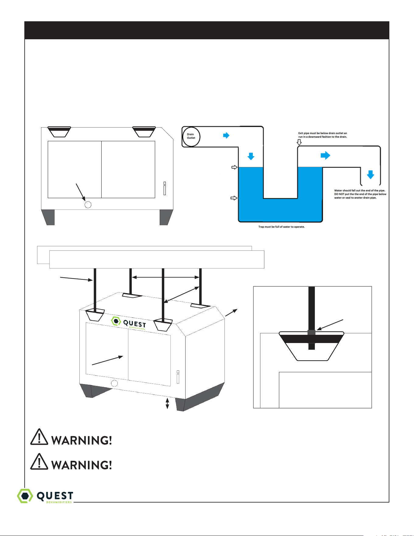
4.3 Condensate Water Removal
Condensate drains by gravity via the drain port. Use 3/4” male NPT PVC pipe. An optional condensate pump kit may be
installed if a lift is required to dispose of the condensate. Optional parts list for information on the kit.
Follow Diagram
Level unit within 2°
4.4 Hanging Diagram
Hanging installation must meet all state and local codes.
Installation should be done by a qualified agency in accordance with these
instructions. The qualified service agency installing this high eciency
refrigeration system is responsible for the installation.
Parts Needed: 4 pieces 3/8” threaded rod (not included)
4 - 3/8” threaded jam nuts (not included)
3/4” drain port
Min 6”
28.95
27.25
3/8” threaded rod
Intake Air
Treated Air
3/8” Jam Nuts
5.56”
1-877-420-1330
Quest 876 Installation, Operation and Maintenance Instructions
7
www.QuestClimate.com
Check the supporting structure to be used to verify that it has sucient
load carrying capacity to support the weight of the unit. Suspend the
unit only from the threaded nut retainers. Do NOT suspend from the
cabinet.
Recommended maximum hanger rod is 6 feet (1.8m)
5. Control Options
The Quest 876 Dehumidifier is controlled by an external remote humidistat through a 24V terminal block. External
control NOT provided.
5.1 Humidity Control
A 24VAC signal is sent by the remote humidistat signals the fan or fan and compressor to actuate.
Quest Control Options:
• DEH 3000R
• Honeywell Humidistat
• Any 24V signal to Dehumidify
Low Voltage Hazard
Can cause equipment damage
Disconnect power before beginning installation.
5.2 24VAC Wiring
The terminal block, low voltage circuit breaker, and power switch are located on the intake side of the unit. Turn the
power switch to the o position while wiring the unit.
FLOAT: {External normally closed dry contact float switch.} No voltage may be applied to the float switch.
FLOAT: Applying voltage may damage the control and void the warranty. {If no float is used in the system, leave
the jumper connected to the terminal block.}
DEHU: Dehumidificaton (compressor and fan operation).
R: 24VAC output
FAN: Fan operation only.
C: 24VAC neutral (common)
Note:
External devices can be powered between 24V/COM (10VA max).
24V circuit is protected by circuit breaker
C
FAN
R
DHUM
(COMPRESSOR
AND FAN)
FLOAT
FLOAT
1-877-420-1330
Quest 876 Installation, Operation and Maintenance Instructions
8
www.QuestClimate.com
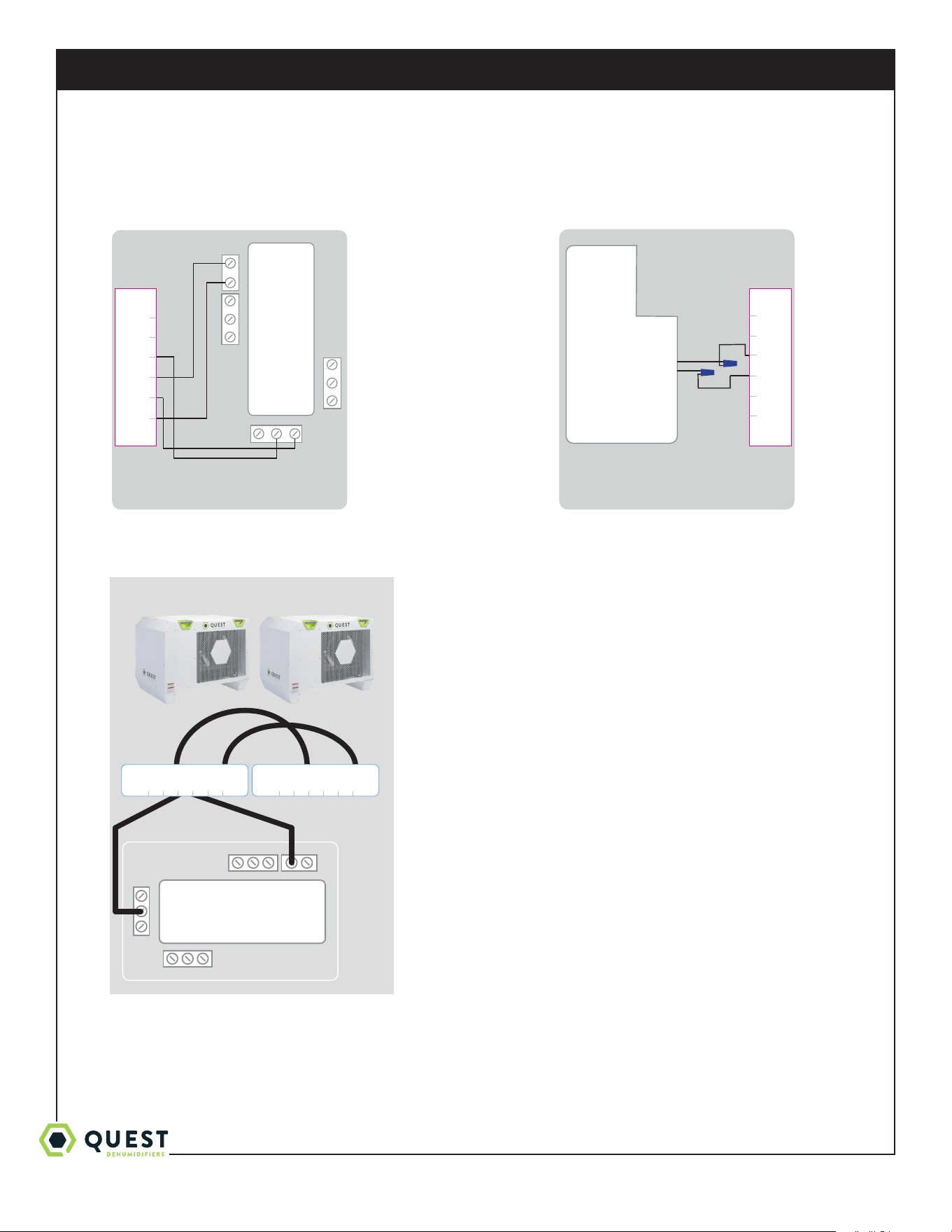
5.2A DEH 3000R Control 5.2B HONEYWELL Remote Humidistat
5.2C Daisy Chain
24VAC
COMP FAN
HONEYWELL REMOTE HUMIDISTAT
WIRING DIAGRAM
QUEST DEH 3000R CONTROL
WIRING DIAGRAM
Red
Black
C
FAN
R
DHUM
(COMPRESSOR
AND FAN)
FLOAT
FLOAT
C
FAN
R
DHUM
(COMPRESSOR
AND FAN)
FLOAT
FLOAT
24VAC
COMP FAN
HONEYWELL REMOTE HUMIDISTAT
WIRING DIAGRAM
QUEST DEH 3000R CONTROL
WIRING DIAGRAM
Red
Black
C
FAN
R
DHUM
(COMPRESSOR
AND FAN)
FLOAT
FLOAT
C
FAN
R
DHUM
(COMPRESSOR
AND FAN)
FLOAT
FLOAT
Unit 1 Unit 2
C
FAN
R
DHUM
(COMPRESSOR
AND FAN)
FLOAT
FLOAT
C
FAN
R
DHUM
(COMPRESSOR
AND FAN)
FLOAT
FLOAT
24V AC
COMPFAN
1-877-420-1330
Quest 876 Installation, Operation and Maintenance Instructions
9
www.QuestClimate.com
6. Maintenance
Do not operate the unit without the filter or with a less eective filter.
Filter non-compliance invalidates the product warranty.
6.1 Standard Air Filter
The Quest 876 Dehumidifier ships with two standard MERV 13 ecient pleated fabric filters. This filter should be
checked every six months. Operating the unit with a dirty filter will reduce dehumidifier capacity and eciency.
To access the air filter, the filter should be readily visible and can be removed by pulling it straight out of the Quest 876
Dehumidifier.
For agriculture, we recommend changing the filter with every grow cycle.
7. Service
Servicing the Quest 876 with its high pressure refrigerant system and
high voltage circuitry presents a health hazard which could result in
death, serious bodily injury, and/or property damage. Only qualified
service personnel should service this unit.
7.1 Warranty
A warranty certificate has been enclosed with this unit; read it before any repair is initiated. If a warranty repair is
required, call the factory first at 1-877-420-1330 for warranty claim authorization and technical assistance.
7.2 Technical Description (Non standard patented)
The Quest 876 Dehumidifier uses a refrigeration system to remove moisture from incoming air, and add heat to the air
that is discharged.
Hot, high-pressure refrigerant gas is routed from the compressor to the condenser coil. The refrigerant is cooled and
condensed by giving up its heat to the air that is about to be discharged from the unit. The refrigerant liquid then passes
through a filter/drier and expansion drier which causes the refrigerant pressure and temperature to drop. It next enters
the evaporator coil where the cool refrigerant absorbs heat from the incoming air and evaporates.
The compressor evacuates the cool refrigerant vapor from the evaporator and compresses it to a high pressure and
temperature to repeat the process.
1-877-420-1330
Quest 876 Installation, Operation and Maintenance Instructions
10
www.QuestClimate.com
8. Ducting Guidelines
Quest 876 is intended for use in statics under .5”WG.
• Ducting either the intake or exhaust uses custom Therma-Stor Intake and Exhaust Duct Kits.
• Grills or diusers on the duct ends must not excessively restrict airflow.
• Eective dehumidification may require ducting to be branched to isolated or stagnant flow areas. Be sure to use
appropriate size duct branches to maintain proper feed throughout the ducting system.
• System control should be placed remotely from the dehumidifier in a central location.
• Intake and exhaust ducting should have a minimum of 4 feet from the unit before any turns and maximum of 25’ for
total run.
Do not connect with a static pressure greater than +.5”wg. Contact
technical support for additional details.
9. Display
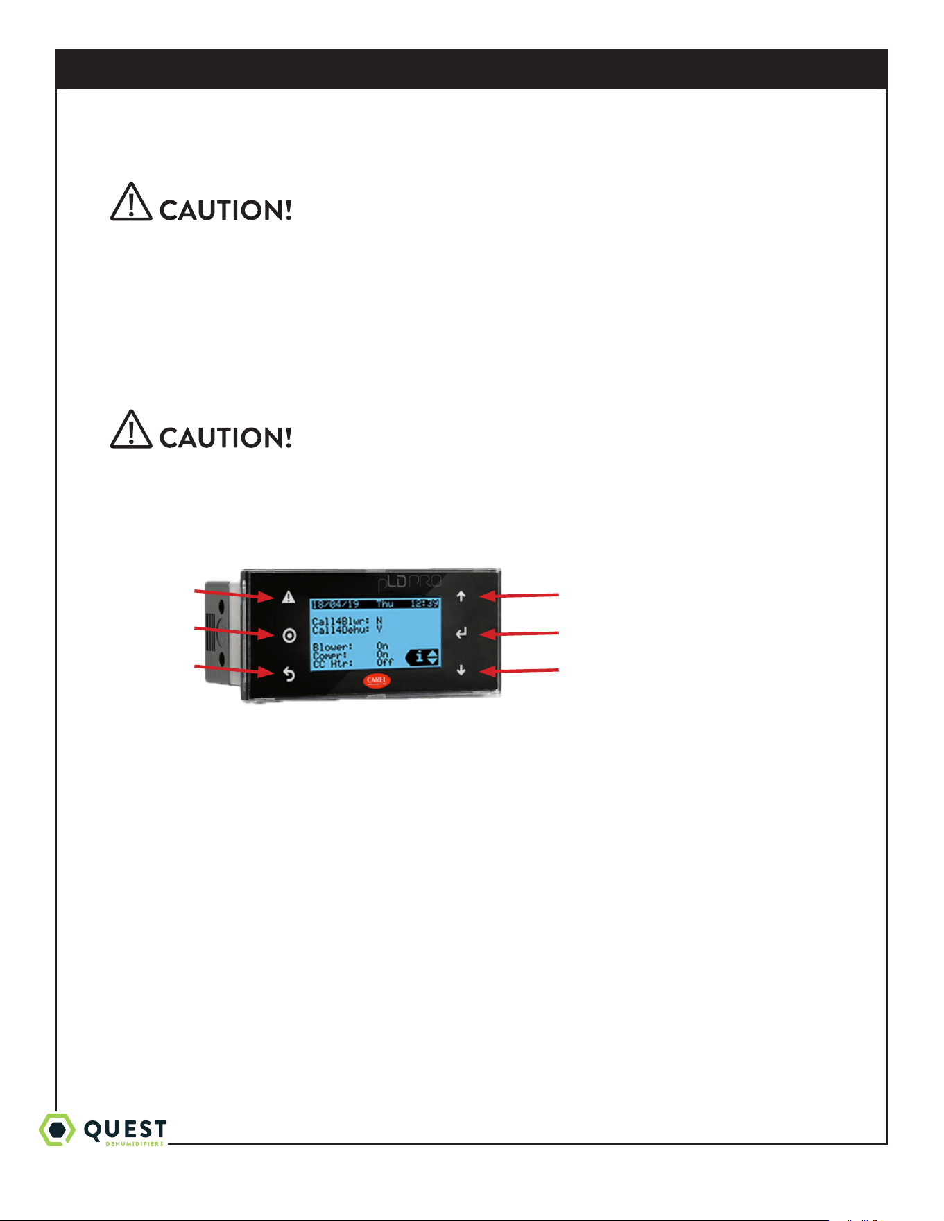
9.1 User Interface
The main status screen is shown:
Left side buttons (top to bottom):
• Alarm – press at any time to check active alarms.
• Prg/Bullseye – press at any time to access settings and menus.
• Escape – press at any time to move to the previous menu.
Right side buttons (top to bottom)
• Up
* On a menu selection screen - moves cursor up.
* On an editable value – increases the value. Press and hold to change the value faster.
* If cursor is in upper left corner of a screen – moves to previous screen.
• Enter
* On a menu selection screen – enters the highlighted menu.
* On an editable value – saves the current value and moves to the next editable item on the screen.
Alarm
Prg/Bullseye
Escape
Up
Enter
Down
1-877-420-1330
Quest 876 Installation, Operation and Maintenance Instructions
11
www.QuestClimate.com
• Down
* On a menu selection screen – moves cursor down.
* On an editable value – decreases the value. Press and hold to change the value faster.
* If cursor is in upper left corner of screen – moves to next screen.
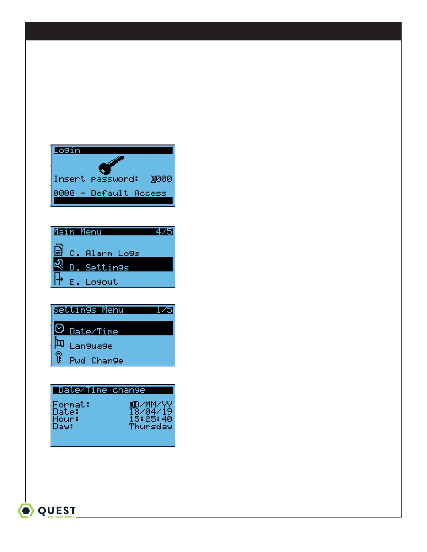
9.2 Settings Change Example: Changing Date Display Format
1. From any screen, press the Prg/Bullseye key. This will prompt for a password.
2. Press Enter four times to access the menu. Then, press Up/Down keys until Settings is highlighted.
3. Press Enter to enter Settings menu. Then, press Up/Down until Date/Time is highlighted.
4. Press Enter to select Date/Time. Then, press Enter again to move the cursor to the Format field.
1-877-420-1330
Quest 876 Installation, Operation and Maintenance Instructions
12
www.QuestClimate.com
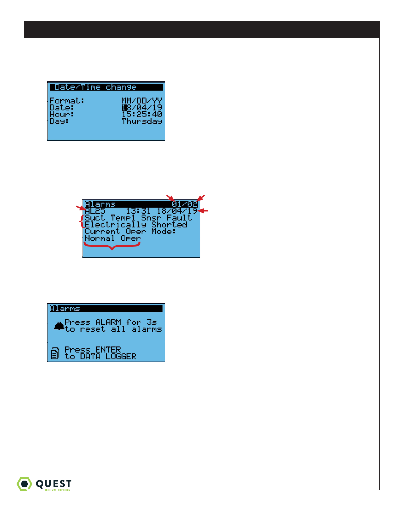
5. Press the Up/Down keys to cycle through the options. Once MM/DD/YY is displayed, press Enter. This will save the
new value, and will move the cursor down to the date field.
6. Press Escape three times to get back to the main status screen.
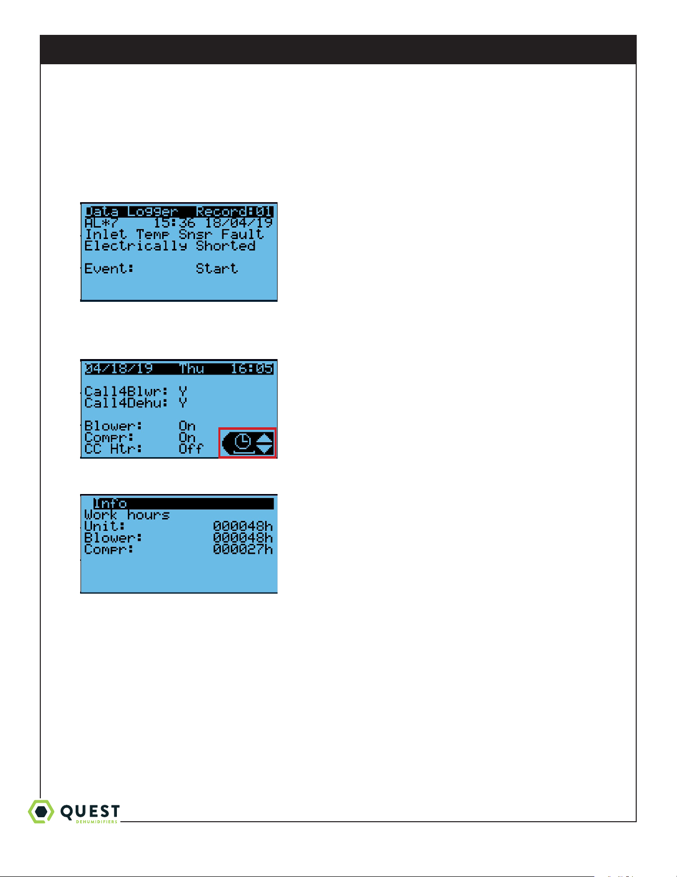
9.3 Viewing Active Alarms/Alarm Logs
1. From any screen, press the Alarm key. If there are active alarms, this will display a screen like this.
2. Press Up/Down to cycle through all active alarms. The alarms are arranged in order of their alarm code (lowest to
highest). One screen beyond last active alarm, the following screen will be displayed.
* Note that if a fault condition is still present, resetting an alarm will have no eect. Active alarms will
automatically be removed from the list when the fault condition is resolved.
Alarm
Code
Description
of Fault
Operating Mode updates in real-time
Time/Date Alarm was Triggered
Current Alarm
Number
Total Number of
Active Alarms
1-877-420-1330
Quest 876 Installation, Operation and Maintenance Instructions
13
www.QuestClimate.com
3. Press Enter to access the Alarm Log. This allows you to cycle through the 50 most recent alarms, whether they are
active or if they’ve been resolved. These are arranged from newest to oldest. The Alarm Log screen is similar to the
Active Alarm screen, except for a few dierences:
* The Alarm Log screen does not display the current operating mode
* The Alarm Log screen shows both when the alarm was first triggered (Event: Start) and when the fault condition
was resolved (Event: Stop).
9.4 Viewing Unit Run Hours
1. From any screen, press Escape several times to return to the main status screen. Press Up/Down until the clock icon
is displayed in the lower-right of the screen.
2. Press Enter to display the operating hours for the entire unit (compressor or fan), for the blower, and for the
compressor.
1-877-420-1330
Quest 876 Installation, Operation and Maintenance Instructions
14
www.QuestClimate.com
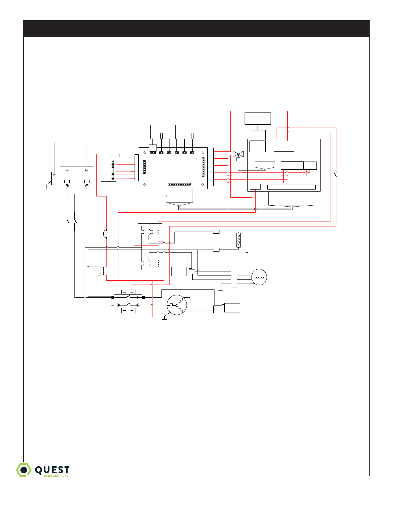
Wiring Diagram of the Quest 876 Dehumidifier
4039867 Rev. B
XFMR
COMPRESSOR
CA PAC ITOR
COMPRESSOR
BLOWER R ELAY
BLK 12
WHT 13
BLOWER
RED
YEL
COMPRESSOR
CONTACTOR
IM PELLE R
CA PAC ITOR
CAREL C .PCO MINI HIGH END PLC
J7
BLK 14
WHT 15
RED 33
BLK
WHT 45
RED 32
YEL 11
J1
J11
NO3
C3/4/5
NO4
C3/4/5
NO5
J2
J8
ID1
ID2
GND
Y1
Y2
GND
WHT 40,41
BLK 43 ,44
3A BREAKER
GR N 51
LINE1
LINE2
GRN
INPUT POWER
1
2
3
4
BRN 48
WHT 41
VIO 46
VIO 47
GR N 36
RED 49
GRY 37
ELECTRONIC
EX VALVE
M
BLU 3
BLK 4
BLK
BLU
BRN
GRN
BLU 2
HP
SWITCH
J9
+5VREF
GND
+VDC
BLK
RED 31,32,33,49
VIO 28
BLK 29
GR N 26
BLU 27
FL OAT
FL OAT
DH UM
R
FAN
C
ORG 50
PRESS
INLE TPROBE
EV AP
SUCT 1 SUCT 2
TB
CAREL
J2
CAREL J1,
J8/J9,J11,
24V
SUCTION PRESS
SENSOR
EVAP THERMISTOR
P ROB E
EVAP THERMISTOR
BULB
SUCT ION
THERMISTOR 1
SUCT ION
THERMISTOR 2
INLET THERMISTOR
BULB
1: U1 (OR G 16)
2: U2 (GRN 17)
3: U3 (BL U 18)
4: GND (BL K 19)
5: U4 (V IO 20)
6: U5 (WHT 21)
7: U6 (BR N 22)
8: GND (BL K 23)
9: U7 (OPEN )
10: U8 (PNK 25)
11: U9 (OPEN)
12: U10 (GRY 24)
1
2
3
4
5
6
7
ORG 5
BLU 6
YEL 7
GR N 8
RED 9
YEL 10
YEL 10
10
9
8
7
6
5
4
3
2
1
RED 30
RED 31
RED 32
RED 33
YEL 35
YEL 34
GRY 37
GR N 36
GR N 36
BLU 2
WHT 39,40,41
BLK 42,43,44
WHT 39
BLK 42
WHT 40
BLK
CRANKCASE
HEATER 50 W
GRN/
YEL
G
G0
V b
HEATER RELAY
1: U1 (OR G 16)
2: U2 (GRN 17)
3: U3 (BL U 18)
4: GND (BL K 19)
5: U4 (V IO 20)
6: U5 (WHT 21)
7: U6 (BR N 22)
8: GND (BL K 23)
9: U7 (OPEN)
10: U8 (PNK 25)
11: U9 (OPEN)
12: U10 (GRY 24)
13: GND (OPEN )
1: WHT
2: BL K
3: GRN
J3- DISP
VTERM
TX/RX-
TX/RX+
GND
4: BL U/WHT
3: GRN
2: RED
1: BL K/YEL
DISPLAY
YEL 35
DISCONNECT
SWITCH, DPST
RED 31
RED 30
YEL 34
1-877-420-1330
Quest 876 Installation, Operation and Maintenance Instructions
15
www.QuestClimate.com
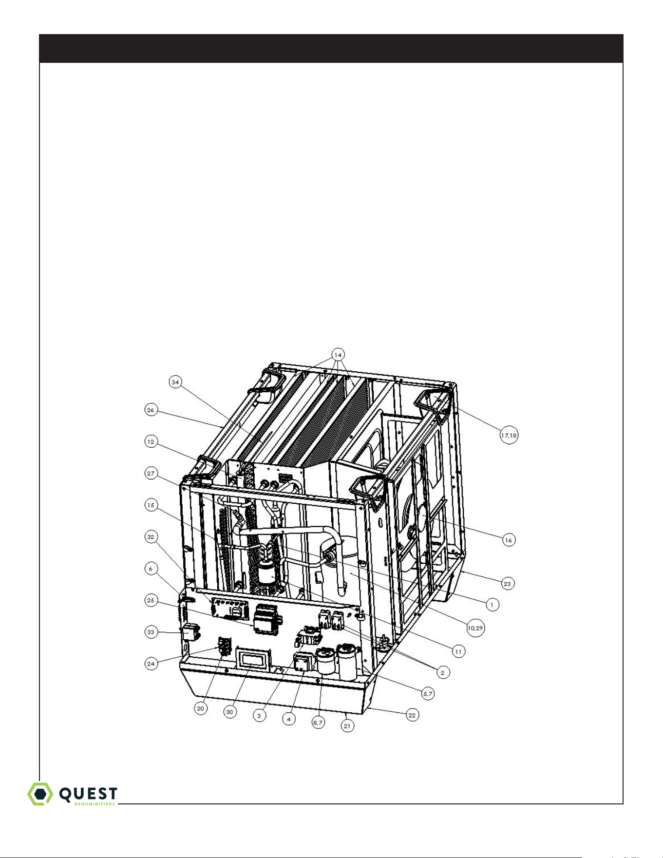
Service Parts List
Item Part No Description
1 4029507 CONTROL,HIGH PRESSURE
2 4029575 RELAY (QTY. 2)
3 4039724 CONTACTOR
4 4031406 TRANSFORMER
5 4035949-07 CAPACITOR, COMP.
6 4036559 CIRCUIT BREAKER
7 4039729 CLAMP,CAPACITOR (QTY. 2)
8 4041557-01 CAPACITOR, IMPELLER
9 4039667 THERMISTOR w/clamp (QTY. 2) (NOT SHOWN)
10 4039603 CPRSR
11 4037702 FILTER,DRIER
12 4039604-04 COIL, EVAP
13 4037699 THERMISTOR bulb (QTY. 2) (NOT SHOWN)
14 4039605-02 COIL, MICRO (QTY. 4)
15 4039661 EEV
16 4039606 FAN,MOTORIZED IMPELLER
17 4038135 HANDLE,POCKET (QTY. 4)
Item Part No Description
1 8 4038136 BEZEL,HANDLE (QTY. 4)
19 4039864 WIRE HARNESS (NOT SHOWN)
20 4038079 LUG,GROUND
21 4038219 FOOT,RUBBER,1.25” DIA (QTY. 4)
22 4038225-01 BRACKET,FOOT,RIGHT
23 4038226-01 BRACKET,FOOT LEFT
24 4038215 BLOCK, WIRING
25 4039948 PLC
26 4038233 FILTER 18x20x2 (QTY. 2)
27 4039862 PRESSURE TRANSDUCER
28 4039932 CPRSR WIRE HARNESS (NOT SHOWN)
29 4039863 CRANKCASE HEATER
30 4041558 PLC DISPLAY
31 4041559 DISPLAY CABLE ASSEMBLY (NOT SHOWN)
32 4039875 P CB
33 4039866 SW ITC H
34 4034716-08 THERMISTOR probe
PART NO. QTY. DESCRIPTION
4020175 1 Controller, Humidity
4028531 1 DEH 3000R Control, Remote
PART NO. QTY. DESCRIPTION
4022220 1 Kit, Pump
4038642 1 Kit, Intake Duct
4039868 1 Kit, Exhaust Duct
Optional Parts List

1-877-420-1330
Quest 876 Installation, Operation and Maintenance Instructions
16
www.QuestClimate.com
Quest 876 Dehumidifier Limited Warranty
WARRANTOR:
Therma-Stor LLC
4201 Lien Rd
Madison, WI 53704
Telephone: 1-800-533-7533
WHO IS COVERED: This warranty extends only to the original end-user of the Quest 876 Dehumidifier dehumidifier,
and may not be assigned or transferred.
FIRST YEAR WARRANTY: Therma-Stor LLC warrants that, for one (1) year the Quest 876 Dehumidifier dehumidifier
will operate free from any defects in materials and workmanship, or Therma-Stor LLC will, at its option, repair or replace
the defective part(s), free of any charge.
SECOND THROUGH FIFTH YEAR WARRANTY: Therma-Stor LLC further warrants that for a period of five (5)
years, the condenser, evaporator, and compressor of the Quest 876 Dehumidifier dehumidifier will operate free of
any defects in material or workmanship, or Therma-Stor LLC, at its option, will repair or replace the defective part(s),
provided that all labor and transportation charges for the part(s) shall be borne by the end-user.
END-USER RESPONSIBILITIES: Warranty service must be performed by a Servicer authorized by Therma-Stor LLC.
If the end-user is unable to locate or obtain warranty service from an authorized Servicer, he should call Therma-Stor
LLC at the above number and ask for the Therma-Stor LLC Service Department, which will then arrange for covered
warranty service. Warranty service will be performed during normal working hours.
The End-user must present proof of purchase (lease) upon request, by use of the warranty card or other reasonable and
reliable means. The end-user is responsible for normal care. This warranty does not cover any defect, malfunction, etc.
resulting from misuse, abuse, lack of normal care, corrosion, freezing, tampering, modification, unauthorized or improper
repair or installation, accident, acts of nature or any other cause beyond Therma-Stor LLC's reasonable control.
LIMITATIONS AND EXCLUSIONS: If any Quest 876 Dehumidifier Dehumidifier part is repaired or replaced, the new
part shall be warranted for only the remainder of the original warranty period applicable thereto (but all warranty periods
will be extended by the period of time, if any, that the Quest 876 Dehumidifier Dehumidifier is out of service while
awaiting covered warranty service).
UPON THE EXPIRATION OF THE WRITTEN WARRANTY APPLICABLE TO THE Quest 876 Dehumidifier
DEHUMIDIFIER OR ANY PART THEREOF, ALL OTHER WARRANTIES IMPLIED BY LAW, INCLUDING
MERCHANTABILITY AND FITNESS FOR A PARTICULAR PURPOSE, SHALL ALSO EXPIRE. ALL
WARRANTIES MADE BY THERMA-STOR LLC ARE SET FORTH HEREIN, AND NO CLAIM MAY BE MADE
AGAINST THERMA-STOR LLC BASED ON ANY ORAL WARRANTY. IN NO EVENT SHALL THERMA-STOR
LLC, IN CONNECTION WITH THE SALE, INSTALLATION, USE, REPAIR OR REPLACEMENT OF ANY Quest
876 Dehumidifier DEHUMIDIFIER OR PART THEREOF BE LIABLE UNDER ANY LEGAL THEORY FOR
ANY SPECIAL, INDIRECT OR CONSEQUENTIAL DAMAGES INCLUDING WITHOUT LIMITATION WATER
DAMAGE (THE END-USER SHOULD TAKE PRECAUTIONS AGAINST SAME), LOST PROFITS, DELAY, OR
LOSS OF USE OR DAMAGE TO ANY REAL OR PERSONAL PROPERTY.
Some states do not allow limitations on how long an implied warranty lasts, and some do not allow the exclusion or
limitation of incidental or consequential damages, so one or both of these limitation may not apply to you.
LEGAL RIGHTS: This warranty gives you specific legal rights, and you may also have other rights which vary from state
to state.