DUAL AC/COOLANT COOLED INDUCTION
HEATER 12KW
Thank you for purchasing a Sealey product. Manufactured to a high standard, this product will, if used according to these
instructions, and properly maintained, give you years of trouble free performance.
IMPORTANT: PLEASE READ THESE INSTRUCTIONS CAREFULLY. NOTE THE SAFE OPERATIONAL REQUIREMENTS, WARNINGS & CAUTIONS. USE
THE PRODUCT CORRECTLY AND WITH CARE FOR THE PURPOSE FOR WHICH IT IS INTENDED. FAILURE TO DO SO MAY CAUSE DAMAGE AND/OR
PERSONAL INJURY AND WILL INVALIDATE THE WARRANTY. KEEP THESE INSTRUCTIONS SAFE FOR FUTURE USE.
1. SAFETY
1.1. ELECTRICAL SAFETY
WARNING! It is the user’s responsibility to check the following:
9 Check all electrical equipment and appliances to ensure that they are safe before using.
9 Inspect power supply leads, plugs and all electrical connections for wear and damage.
9 Ensure that the insulation on all cables and on the appliance is safe before connecting it to the power supply.
8 DO NOT use worn or damaged cables, plugs or connectors.
9 Ensure that any faulty item is repaired or replaced immediately by a Sealey qualied technician.
9 If the cable or plug is damaged during use, switch o the electricity supply and remove from use.
9 Sealey recommend that an RCD (Residual Current Device) is used with all electrical products.
IMPORTANT: Ensure that the voltage rating on the appliance suits the power supply to be used and that the plug is tted with the
correct fuse.
8 DO NOT pull or carry the appliance by the power cable.
8 DO NOT pull the plug from the socket by the cable.
1.2. EXTENSION CORDS
WARNING! If an extension cord is required, only the following specications are approved for use with the induction heater:
- 7.6-meter cord: 2 AWG
- 15.2-meter cord: 1 AWG
Using cords outside these specications may result in overheating or insucient power delivery.
8 DO NOT connect multiple extension cords in series.
9 Use only the specied extension cords listed above.
9 Always fully unwrap extension cords before use. Tightly coiled cords can overheat and pose a re hazard.
9 If the supply cord is damaged, it must be replaced by the manufacturer, its service agent or similarly qualied persons in order to avoid
a hazard.
1.3. GENERAL SAFETY
8 DO NOT touch heating parts with bare hands.
8 DO NOT touch live electrical parts or electrodes with bare skin or wet clothing.
8 DO NOT operate in the vicinity of containers under pressure, or in the presence of explosive dust, gases or fumes.
8 DO NOT cover or stick objects into any of the ventilation holes on the equipment.
8 DO NOT wear clothing containing metal components, such as zippers, rivets, or metallic buttons, while operating the induction heater.
The heater can rapidly heat these metal parts, potentially causing serious burns or igniting the clothing.
WARNING! The magnetic elds created by high currents may aect the operation of pacemakers. DO NOT operate or come within
three feet of an active induction heater, if you have a cardiac pacemaker or any electronic or metal surgical implant. Wearers of vital
electronic equipment should consult their Doctor before using Induction heater, although the magnetic eld generated by the heater
typically extends only a few inches, it can interfere with the function of implanted medical devices. This applies to both users and
bystanders. To prevent accidental exposure, individuals with such implants must stay at least three feet away from the induction heater
while it is in operation.
WARNING! Keep bystanders, children, visitors, and animals at a safe distance while operating the induction heater. Their presence
may cause distractions, increasing the risk of losing control of the equipment and leading to potential injury or damage.
9 Ensure area is adequately ventilated and dry.
9 Before operating the induction heater, remove all metallic objects from your person, including coins, keys, chains, pocket knives,
tokens, and miniature tools. DO NOT carry or wear these items while the heater is in use. The induction heater can rapidly heat metal
objects, posing a serious risk of burns or ignition of clothing.
9 Ensure ambient temperature is between -10 to 40°C
9 Avoid using in bright sunshine or rain.
8 DO NOT use the machine in an environment where the air is polluted with conductive dust or gases.
8 DO NOT overreach; maintain proper footing and balance at all times. Ensuring stable footing and balance allows for better control of
the induction heater, especially in unexpected situations.
8 DO NOT operate the induction heater while under the inuence of drugs, alcohol, or any medication that may impair your judgment or
coordination. Impaired operation increases the risk of accidents and injury.
VS290 Issue 2 19/05/2025
Original Language Version
© Jack Sealey Limited
Refer to
Instructions
Electrical shock
hazard
Wear eye
protection
Wear protective
gloves
Do not use in
the vicinity of a
pacemaker
Warning
magnetic eld
Keep away from
rain
MODEL NO: VS290
Wear
respiratory
protection

8 DO NOT operate the induction heater within six inches of any airbag component. The heat and electromagnetic eld may accidentally
trigger airbag deployment or damage sensitive components.
9 Consult the vehicle manufacturer’s service manual to identify the exact locations of all airbags before working on a vehicle. Keep in
mind that airbags can be located in areas such as the roof, doors, sides of seats, and other locations.
WARNING! Due to the heat generated by the induction coils blistering of painted surfaces will happen if over heated.
9 Children from age 8 years and above, persons with reduced physical, sensory, or mental capabilities those with lack of experience and
knowledge can use the appliance, if they have been given supervision or instruction concerning use of the appliance in a safe way to
understand the hazards involved.
9 Children shall NOT play with the appliance.
9 Cleaning and user maintenance on the appliance shall not be made by children without supervision.
9 The appliance shall be disconnected from its power source during service and when replacing parts.
9 Maintain a clean and well-lit work area. Cluttered or poorly lit environments increase the risk of accidents.
9 Work outdoors whenever possible, provided there is no risk of rain, water, or moisture exposure. If outdoor work is not feasible, ensure
the indoor workspace is dry and well-ventilated. Ventilation fans should be positioned to exhaust air from the inside to the outside.
9 Always keep a fully charged re extinguisher readily accessible when operating the induction heater.
9 Always wear safety goggles when operating the induction heater. Protect your eyes from potential sparks, debris, or accidental
splashes.
9 Fumes and smoke from hot or burning adhesives are toxic. Always wear a dual-lter respirator mask (dust and fume) that is approved
by the appropriate government authority to protect your respiratory health.
9 Wear heat-resistant gloves when operating the induction heater. The heater rapidly heats metal, and handling hot metal surfaces
without protection can result in burns to your hands and ngers.
WARNING! C. HF Radiation: High-frequency (HF) emissions can cause interference. HF radiation may disrupt radio navigation
systems, safety services, communication devices, and computer equipment.
9 Installation should be performed only by qualied personnel familiar with electronic equipment. Improper installation can result in
equipment damage or personal injury.
9 The user is responsible for ensuring that any interference caused by the installation is promptly corrected by a qualied electrician.
9 If notied by the appropriate government communications authority about interference, immediately cease use of the equipment.
Continued operation may violate regulations and result in penalties.
9 Ensure the installation is regularly inspected and maintained. Routine checks help prevent malfunctions and ensure safe operation.
9 Keep all doors and panels of the high-frequency source securely closed during operation. This helps prevent exposure to
electromagnetic radiation and ensures safe, reliable performance.
8 DO NOT use the heating inductor if its insulation is damaged or breached. Damaged insulation can cause sparking upon contact with
the vehicle, creating a serious re hazard, especially when working near fuel tanks, gas lines, or other ammable materials.
8 DO NOT use the heating inductor if the insulation is damaged or compromised. Breached insulation can cause sparking upon contact
with a vehicle, creating a serious re hazard, especially when working near gas lines or fuel tanks.
WARNING! Never attempt to heat aerosol cans, paint cans, or any pressurized containers that store fuels, compressed gases, or
liquids. The heat generated by the induction heater can cause these containers to explode and ignite their contents, resulting in re or
serious injury.
1.4. SAFETY DEVICES
This equipment is water-cooled, using water to regulate the temperature of the electronics, transformer, and tool.
A built-in ow sensor prevents the induction heater from being activated via the control button if the water ow rate is insucient.
Additionally, the system includes sensors to monitor the internal temperature of both the induction heater and the coolant. If
overheating is detected, the equipment will not start, ensuring safe operation.
1.5. RESPIRATORY PROTECTION
Fumes and smoke from hot or burning adhesives are toxic and require proper respiratory protection. Always wear a dual-lter respirator
mask rated for dust and fumes. Ensure the mask ts securely, as beards or facial hair can prevent a proper seal. Filters should be
changed frequently, disposable paper masks are not adequate for this purpose.
1.6. AIRBAG SAFETY PRECAUTIONS
8 DO NOT use the induction heater within 6 inches (15 cm) of any airbag component. The heat generated by the induction heater can
ignite the airbag propellant, causing sudden and unexpected airbag deployment, which may result in serious injury. Always refer to the
vehicle manufacturer’s service manual to determine the exact location of all airbag modules and components before beginning work.
9 Be aware that airbags may be located in roofs, doors, seat sides, dashboards, and other areas depending on the vehicle model.
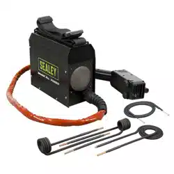
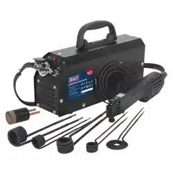
2. INTRODUCTION
Delivers longer-lasting high heat fast and eectively. Ideal for cars, trucks, agricultural machinery, boats and engineering. Suitable for
larger seized nuts and bolts including track rods. Straightening of steel frames and chassis and can pre-heat larger wielding areas.
Variable heat settings, enable the users to apply correct heat for specic jobs. Memory function allows up to ten heat settings to be
stored for the user’s convenience.
3. SPECIFICATIONS
Original Language Version
© Jack Sealey Limited
VS290 Issue 2 19/05/2025
Model No: VS290
Frequency: 14-19kHz
Fuse Rating: 16A
Nett Weight: 104kg
Power Supply Cable Length: 4.7m
Power: 12kW
Product Life Applicable: No
Maximum Weight With Coolant: 144kg
Ingress Protection Rating: IP21
Tank Capacity: 42L
Induction Cable Length: 5m
Cable Length: 4.7m
Temperature Range: 0 to 40°C
Connected Load: 9 kVa
Duty Cycle: 38mins @ 20° C, 8mins o
Cooling System: Water Cooled with
Refrigerator
Original Language Version
© Jack Sealey Limited
4. FUNCTIONS & FEATURES
The device is engineered to heat ferromagnetic
conductive materials by focusing a high-intensity
alternating magnetic eld at the inductor head.
Operating at a frequency of approximately 18 kHz,
the alternating eld induces eddy currents within the
target material. These currents generate localized
heat due to the Joule eect (resistive heating) within
the material’s structure.
The inductor itself remains cool and does not
generate heat; instead, it emits a non-thermal,
alternating magnetic eld, ensuring energy is
transferred eciently and contactlessly to the
workpiece see g.4
4.1. SAFETY DEVICES
The equipment is water-cooled, with cooling applied to the electronics, transformer, and tool. It features a ow sensor that prevents
operation via the control button if the water ow rate is too low. The unit also includes seven internal sensors to monitor the
temperature of the induction heater and cooling water. If any temperature threshold is exceeded, the heater cannot be activated. A
dedicated circuit ensures the hose package includes a protective earth connection. For safety, the equipment is tted with a 16A fuse
and an earth fault breaker.
5. OPERATION
5.1. BEFORE OPERATION
WARNING: DO NOT place the induction heater on uneven or unstable surfaces. Instability may cause the unit to tip over, resulting in
potential personal injury or signicant equipment damage.
5.2. UNPACKING
- Inspect the packaging for any signs of damage upon receipt.
- Carefully remove the instruction manual and all packaging materials.
- IMPORTANT: Ensure that no packaging materials remain near the machine before powering it on, as this may pose a re hazard.
The machine is heavy, weighing about 105Kg (without water), or 145Kg (with water). To avoid the risk of personal injury, minimum need
two men to move the machine o the pallet. See g.5 on the next page.
5.3. COOLANT REFILL
To rell the coolant, add a mixture of clean, decalcied water and 30% propylene glycol through the tube at the back of the machine
until the water level is 2–3 cm below the top of the tank. See g.6 on the next page.
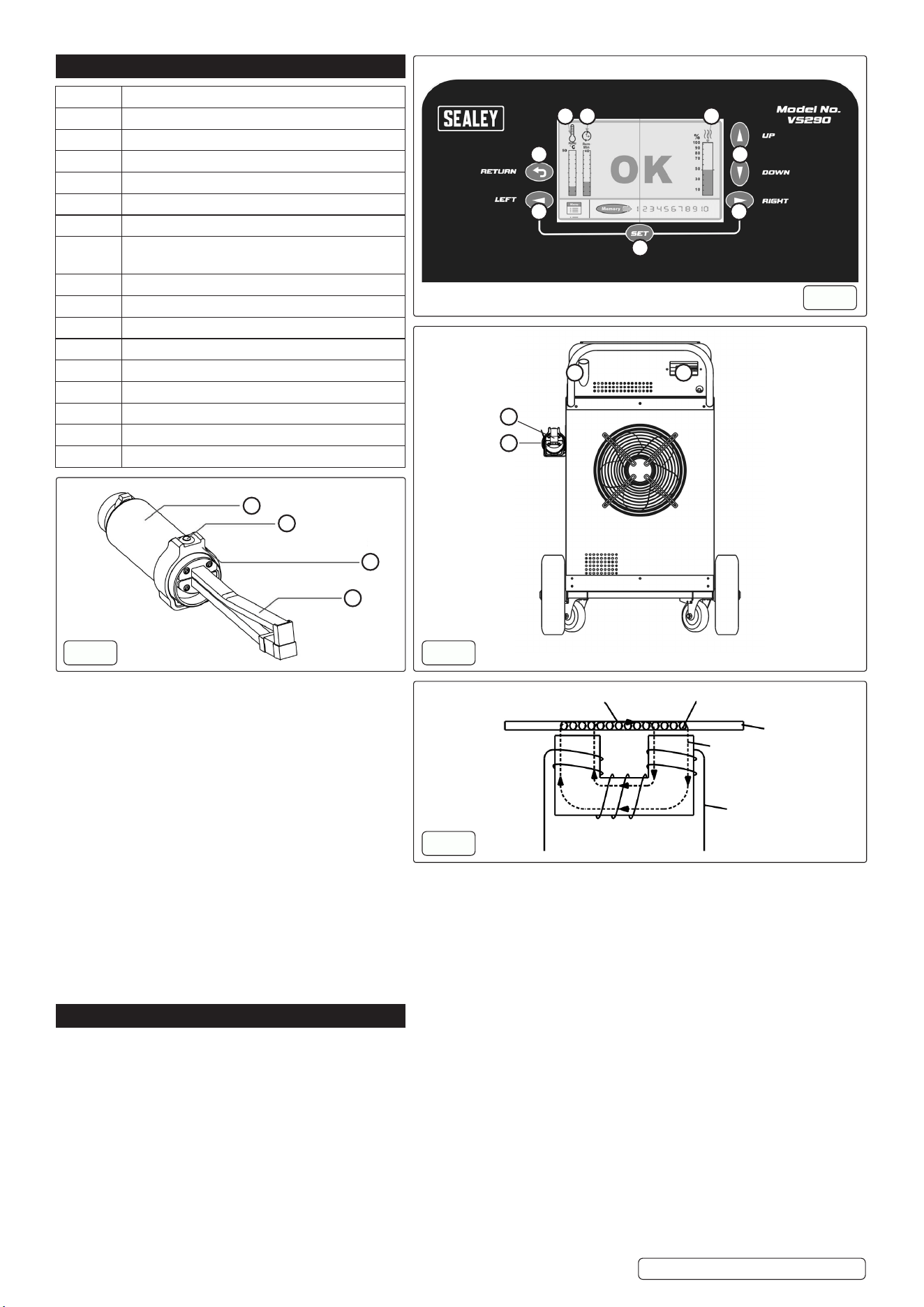
VS290 Issue 2 19/05/2025
Number Function
1 Set (Conrm) key
2 Left key
3 Return key
4 Temperature indication of coolant water in tank
5 Remain cycle time (Cycle duration)
6 Output power indication.
7 Heating power adjust keys, or up and down
keys
8 Right key
9 Transformer unit
10 Inductor button
11 Rotatable ring
12 Induction unit
13 Coolant rell
14 Earth fault breaker
15 Inductor unit
16 Inductor unit holder
1
Control Panel
g.1
9
10
11
12
g.2
Heat Eddy
Sheet iron
Coil with high
frequency
current
Electromagnetic
eld
g.4
2
3 7
8
4 5 6
13
15
16
14
g.3
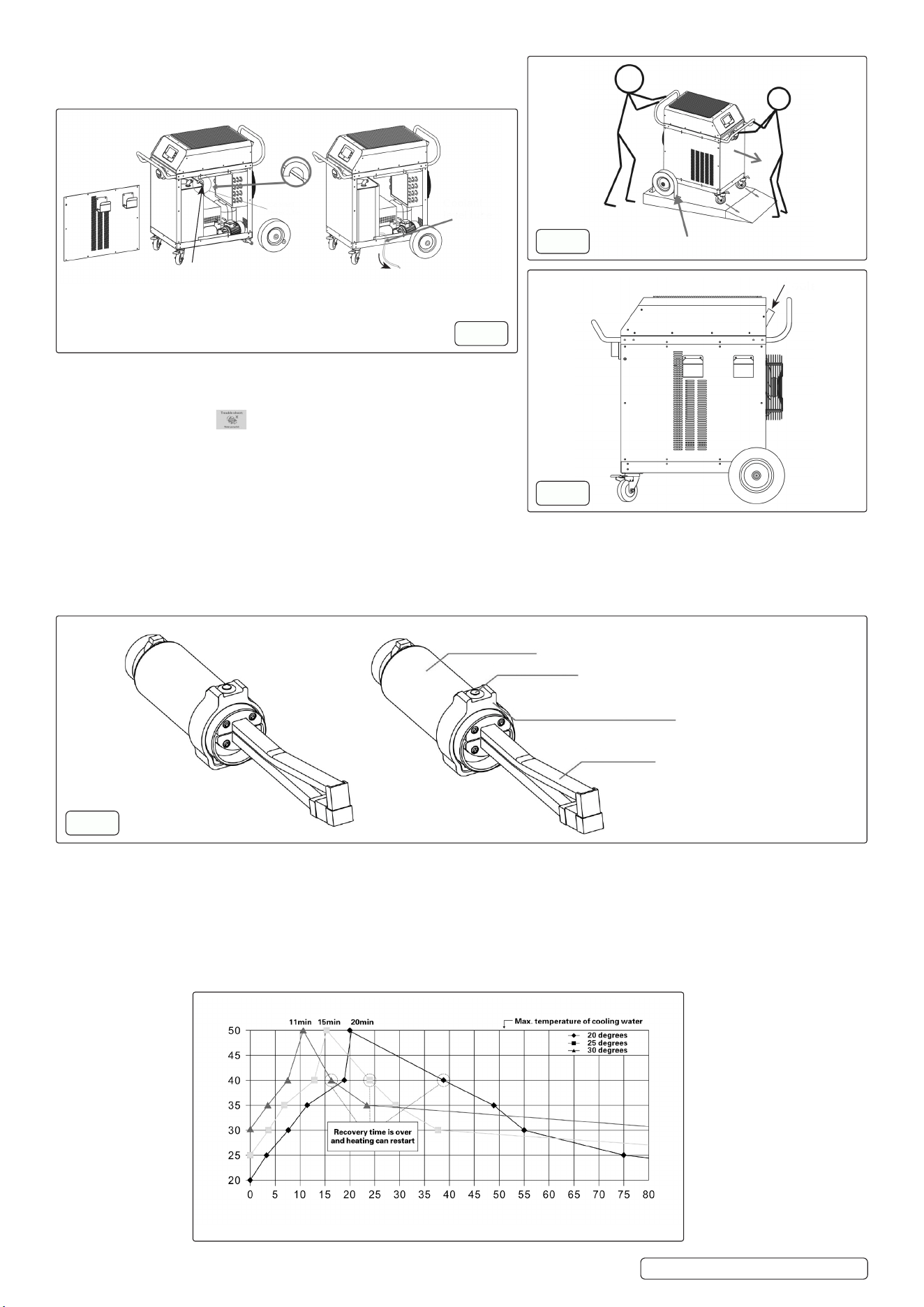
5.4. COOLANT DRAINING PROCEDURE
For repairs or replacement of used coolant, a technician should drain
the coolant from the tank by following the procedures in g.7
5.5. INITIAL COOLANT FILLING
WARNING! The machine should be lled with coolant for the rst
time or after the old coolant has been discharged; if a screen image
message appears on the screen at startup, this is normal and the
machine can usually resume operation after one or a few restarts.
5.6. READY
To prepare the machine, turn on the fuse and earth fault breaker at the
back, switch on the power on the front panel to start initialization, and
after about 30 seconds when the screen shows “OK,” the machine is
ready for operation by pressing the inductor button for induction heating.
5.7. INDUCTOR BUTTON FUNCTION (g.8)
The inductor button is attached to the transformer via a rotatable ring. During the heating process, the “OK” indication turns o, and the
display changes to show that heating is in progress. Simultaneously, the remaining cycle time and the machine’s overheating protection
status are displayed on the left side of the screen in the form of two parallel scales.
NOTE: Ensure proper coolant circulation is maintained during operation to prevent overheating.
5.8. CYCLE TIME
The maximum cycle time for the equipment is 38 minutes at maximum heating power, followed by approximately an 8-minute break
between cycles. If lower heating power is used, the cycle time increases proportionally to the reduction in output power. The cycle time
is displayed on a scale on the left side of the screen and is continuously updated during operation, allowing the user to easily monitor
their work.
NOTE: CAUTION When the coolant temperature is below 20°C and the machine is powered on, it will automatically enter “Sleep”
mode after 12 minutes of inactivity to save energy and extend its lifespan. The machine will remain in this mode until either the control
or inductor button is activated. To resume operation from “Sleep” mode, press the heating button twice.
VS290 Issue 2 19/05/2025
Original Language Version
© Jack Sealey Limited
Remove the side panel to access the coolant level tube, then use the tube to
drain the waste coolant.
Heating time in minutes
Cooling water temperature °C
g.7
Coolant level tube
Coolant level
tube
g.5
Remove
g.6
Coolant rell
Transformer unit
Inductor button
Rotatable ring
The angle is adjustable to accommodate
dierent hand positions
g.8
The machine is automatically set at 80% heating power. If an alternative. Heating power is required, set the arrow buttons on the right
side of the screen; a scale shows the decrease or increase of the setting in steps of 5%. When the machine is switched o, he heating
power setting returns to the default 80%.
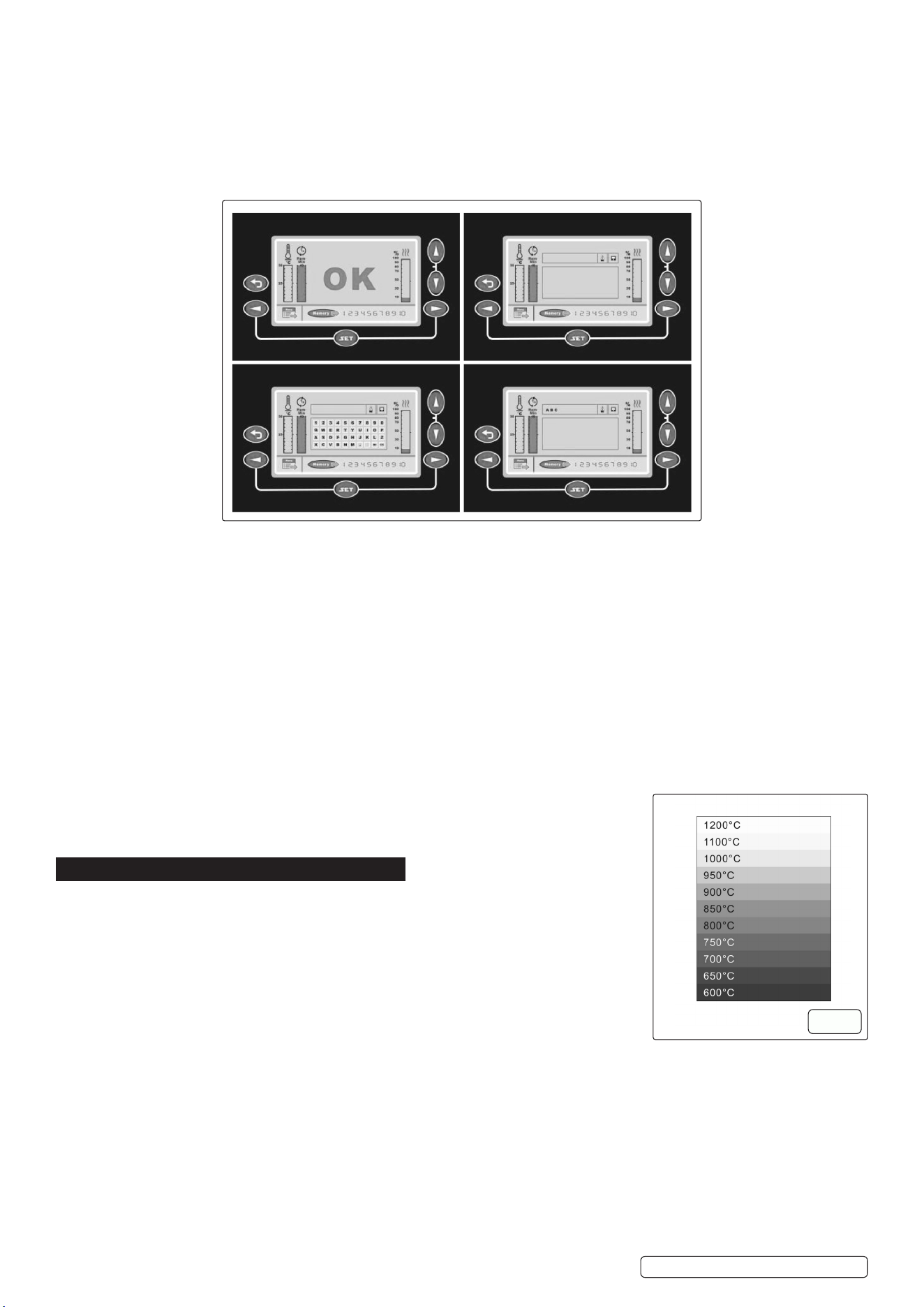
5.9. MEMORY SETTING
The preset heating power is provided for reference only; users can adjust the power based on the heated item and required speed.
For convenience, there are 10 customizable memory keys available in the manual. These keys allow users to save both the adjusted
heating power and the name of the corresponding heating item.
To save the heating part name and output power percentage, follow these steps:
5.10. SAVING AND RECALLING MEMORY SETTINGS:
To save a heating part name and output power percentage:
1. Use the arrow keys to set your desired output power percentage (Status A).
2. Use the arrow keys to select a memory position (1–10), then press “SET” to conrm (Status B).
3. Use the arrow keys to select letters for naming the heating part, pressing “SET” after each letter (Status C).
4. To delete a letter, navigate to the delete option in Status C and press “SET.”
5. Once the name input is complete, press the conrmation button to proceed to Status E.
6. In Status E, conrm the save by selecting the save option and pressing “SET.” The setting will be stored even after the machine is
turned o.
5.11. TO RECALL A SAVED SETTING:
1. In Status A, use the arrow keys to select a memory position (1–10), then press “SET.”
2. The saved part name and output power percentage will appear; press the inductor button to use the setting.
5.12. SWITCHING OFF THE MACHINE
After turning o the switch(es) on the panel and/or the back of the machine, high voltage may still remain inside for a short time, but the
machine will discharge it automatically; to ensure complete discharge, turn o all switch(es) and wait at least 15 minutes.
5.13. USE/OVERHEATING
Controlling the heating point of the workpiece is crucial, as overheating can weaken the
workpiece and shorten the inductor’s lifespan; a simple method is to monitor the colour of the
heating point, ensuring it does not exceed 800°C–900°C. See g.9
6. MAINTENANCE
6.1. MODIFICATION WARNING
8 DO NOT remove covers or perform any work on the induction heater while it is connected to
the mains power supply.
- The equipment must not be modied in any way without prior written approval from the
manufacturer.
- The user is fully responsible for any technical failures resulting from:
- Improper use.
- Inadequate maintenance.
- Accidental damage.
- Unauthorised repairs or modications by anyone not authorised by the manufacturer.
Service and Maintenance Warning
- All major servicing or maintenance must be performed by authorised service personnel.
- High-voltage risk: Internal components carry a dangerous electric charge.
Electrical Safety
- Always disconnect the machine from the power source before carrying out any:
- Cleaning.
- Maintenance.
- Service or repair.
Personal Safety
8 DO NOT wear metallic objects (e.g., watches, rings, bracelets) during operation.
- Metal accessories may become dangerously hot due to induction elds and can cause burns.
VS290 Issue 2 19/05/2025
Original Language Version
© Jack Sealey Limited
g.9
A B
C E
IMPORTANT Note on Warranty
- Any attempt by the user to interfere with the machine during the warranty period in an eort to rectify faults will void the warranty
provided by the supplier.
6.2. INDUCTION HEATER
- Keep the unit clean by wiping it down regularly with a damp cloth and mild soapy water.
- Inspect wiring and coolant hoses to ensure they are free from damage or wear.
- If damage or coolant leakage is found:
- Immediately switch o the machine.
- Disconnect the power supply.
- Contact Sealey Service Centre for assistance.
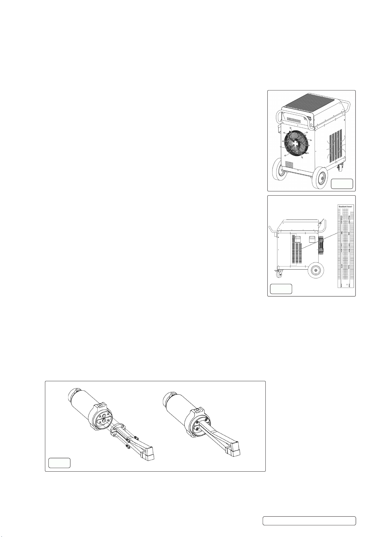
6.3. COOLING UNIT & PLACEMENT MAINTENANCE
- Ensure cooling vents and airow paths (on both sides and underneath the unit) are not
obstructed. See g.10
- Clean the cooling grille and ventilation openings using a damp soapy cloth.
- Regularly verify the cooling fan is operating correctly.
- Good airow is essential for reliable operation and to prevent overheating.
Checking the Coolant Level
- To ll the coolant:
The cooling unit is not pre-lled with coolant and must be lled with a mixture of clean,
decalcied water and 30% propylene glycol; add the coolant through the tube at the back of
the machine until the water level is 2–3 cm below the top of the tank. See g.11
WARNING! Only ll the reservoir with clean water, adding anti-freeze if necessary, using
other substances may cause personal injury or equipment damage.
IMPORTANT! DO NOT use salty, brackish, or very hard water; if water quality is uncertain,
use a mixture of water and anti-freeze.
IMPORTANT! If the induction heater is used in environments where the temperature falls
below freezing, antifreeze must be used; the recommended mixture is 30% propylene glycol.
6.4. INDUCTOR UNIT HANDLING & MAINTENANCE
- Ensure the inductor is securely mounted in the inductor handle before operation.
- The contact surfaces between the handle and the inductor must be clean and free of oil, dirt,
or debris. Use alcohol to clean these surfaces.
8 DO NOT use any inductor that has:
- A cracked eld amplier, or
- Signs of water leakage.
When performing maintenance or repair tasks, the inductor may become tacky due to paint
residue.
This is normal and does not aect equipment function or performance.
6.5. REPLACING THE INDUCTOR UNIT
A replacement inductor can be ordered from Sealey Service Centre. To install the new unit,
follow these steps carefully:
1. Turn O the Machine.
Ensure the induction heater is powered o and unplugged from the mains supply before
beginning any work.
2. Remove the Existing Inductor.
Use an Allen key to detach the current inductor unit from the handle.
3. Inspect and Clean Contact Surfaces
- Check that the terminals on both the inductor unit and the handle are clean and free of debris.
- If dirty, gently polish with soft emery cloth, then clean with alcohol.
8 DO NOT use grinders or wire brushes, as these may damage the contact surfaces.
4. Install the New Inductor Unit g.12
- Use only the original bolts, washers, and O-rings supplied with the new unit.
- Secure the inductor by hand-tightening the bolts.
- Ensure all components are properly seated and tightened, DO NOT overtighten.
IMPORTANT NOTE: on Securing the Inductor Unit
When replacing the inductor unit, ensure that all bolts are rmly and properly tightened.
Failure to secure the screws correctly can result in the threaded insert becoming detached and sticking to the screw. This may cause
damage to the insert and potentially lead to it being pulled out during future inductor replacements.
VS290 Issue 2 19/05/2025
Original Language Version
© Jack Sealey Limited
g.10
g.11
g.12
6.6. EARTH FAULT BREAKER
Test the machine’s earth fault breaker once a month by pressing the test button to ensure proper functioning.
WARNING! Unauthorised Modications
8 DO NOT modify the equipment or its components without the prior written permission of the manufacturer.
The user is liable for any technical failures resulting from:
- Improper use.
- Inadequate maintenance.
- Damage.
- Unauthorised repairs or modications by any party other than the manufacturer or one specically authorised by the manufacturer.
All major service and maintenance must be performed exclusively by the manufacturer’s authorised service personnel. Contact Sealey
Service Centre.
Risk of electric shock. Unauthorised servicing may result in serious injury or equipment damage.
8 DO NOT remove any cover plates or perform maintenance on the induction heater without rst disconnecting it from the mains power
supply. Risk of electric shock.
Disconnect the induction heater from the mains power supply before performing any service, cleaning, or maintenance.
Failure to do so may result in electric shock.
6.7. STORAGE
Store in a clean, dry, and well-ventilated area, protected from dust, moisture, and direct sunlight. Ensure it is placed on a stable
surface, with coolant lines and electrical connections secured to prevent damage. Avoid exposure to extreme temperatures and
corrosive substances.
6.8. PACKAGING AND END-OF-LIFE DISPOSAL
All packaging materials used with this equipment are recyclable. Please ensure they are disposed of through appropriate recycling
channels.
The induction heater is designed with a high level of recyclability. However, some components may contain hazardous substances and
must not be discarded with regular household waste.
For guidance on environmentally responsible disposal, consult your local electronic waste disposal regulations.
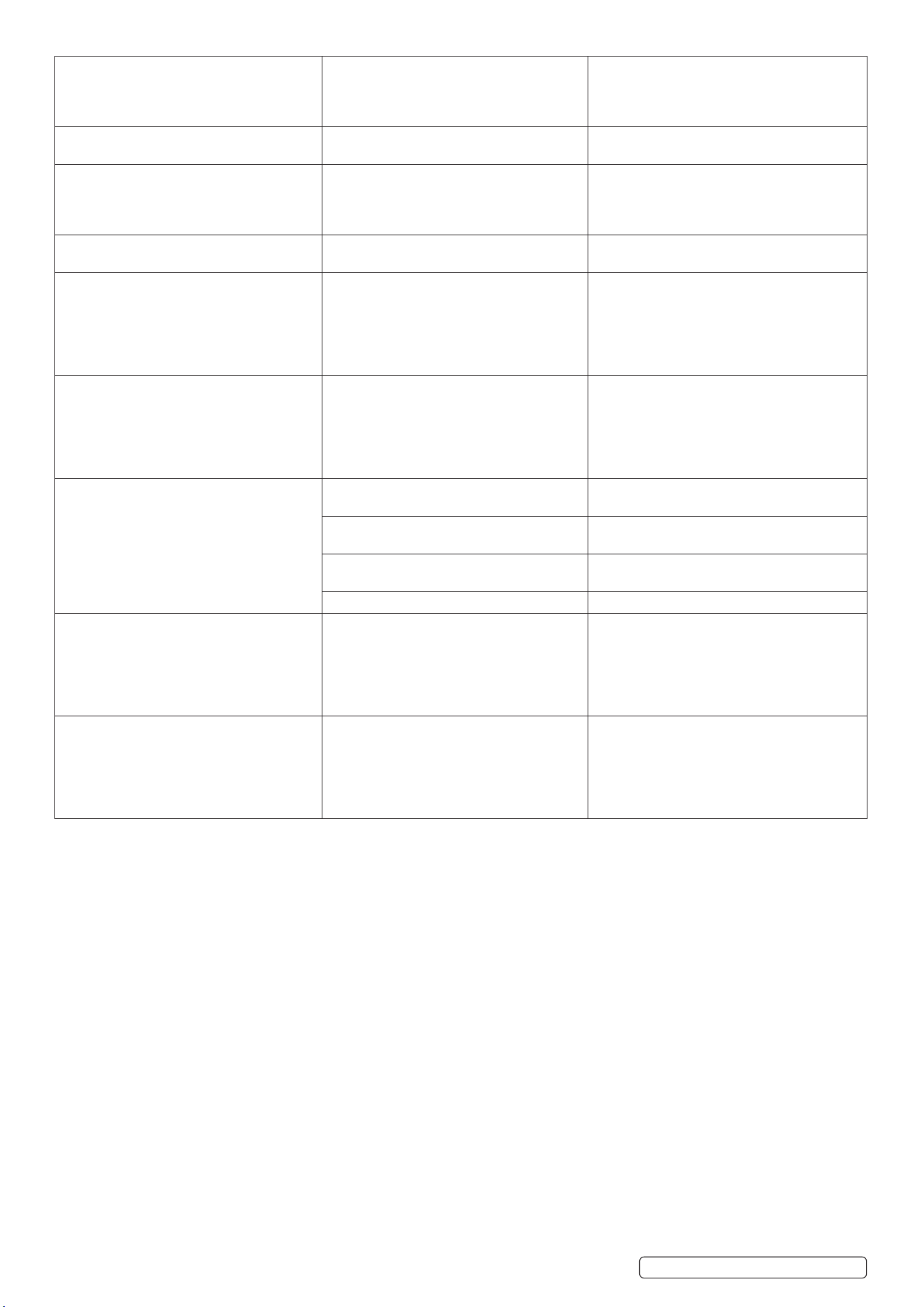
7. TROUBLESHOOTING
VS290 Issue 2 19/05/2025
Original Language Version
© Jack Sealey Limited
PROBLEM CAUSE CORRECTIVE ACTION
Overheat, waiting for Recovery. The machine has overheated. 1. wait for it to cool down before resuming
operation.
2. The machine has overheated; wait until the
cooling cycle is nished. If the fault reoccurs,
contact Sealey Service Centre.
Refrigeration Failure. Refrigeration Failure. Check the coolant level and system
components. If the issue persists, contact
Sealey Service Centre.
Water Pump Failure. Water pump. The water pump is not functioning properly;
check for blockages, coolant level, and pump
connections. If the problem continues, contact
Sealey Service Centre.
Inverter Circuit Failure (IGBT or Connecting
PCB).
Inverter circuit. A fault has occurred in the inverter circuit,
possibly involving the IGBT or connecting
PCB; discontinue use immediately and contact
Sealey Service Centre for inspection and
repair.
Cooling Fan Failure. Cooling fan. The cooling fan is not operating correctly;
check for obstructions or loose connections. If
the issue persists, stop using the machine and
contact Sealey Service Centre.
Power Frequency Incompatibility. Power frequency inconformity with the
equipment.
The machine can only operate on a 50Hz
(or 60Hz) power supply; ensure the power
frequency matches the machine’s requirement
to avoid malfunction.
Water Flow Failure. Insucient or no water ow detected. Check the coolant level, water pump, and
hoses for blockages or leaks. If the issue
persists, contact Sealey Service Centre.
Earthing Failure. The machine is not properly grounded. Check the earth connection immediately to
prevent electrical hazards. Do not operate the
machine until the issue is resolved.
Temperature Sensor Line Failure. Temperature circuit error. Check for loose connections, damage, or
faulty wiring. If the problem persists, contact
Sealey Service Centre for assistance.
Power Phase Loss. A phase is missing in the power supply. Check the power connections and ensure all
phases are functioning properly. If the issue
persists, contact Sealey Service Centre.
Troubleshoot icon on screen after
initialization.
If the screen displays the troubleshoot icon
after turning on and initialization.
Indicates a system issue. Contact Sealey
Service Centre for assistance.
VS290 Issue 2 19/05/2025
Original Language Version
© Jack Sealey Limited
Inductor overheating and spark issue. If the inductor gets hot and sparks appear
between the inductor and transformer.
Turn o the machine immediately. Check for
any loose connections or damage, and if the
issue persists, contact Sealey Service Centre
for inspection and repair.
Water leak at the inductor. O-rings damaged or the inductor is worn out. Order new O-rings or a new inductor from
Sealey Service Centre.
Hose package water leak. If the hose package is damaged. Inspect it for cracks, loose ttings, or worn
seals. Turn o the machine and repair or
replace the damaged components. If the issue
persists, contact Sealey Service Centre.
Sparks between inductor and workpiece. Worn inductor. Order replacement from Sealey Service
Centre.
Crack formation in the inductor. Overheated work piece has caused the eld
amplier to crack.
If cracks are found in the inductor, discontinue
use immediately as this can lead to malfunction
or safety hazards. Inspect for damage and
replace the inductor if necessary. Contact
Sealey Service Centre for further evaluation or
replacement.
No Heat Output from Machine. Inductor not properly secured / Missing
power phase.
If the machine does not provide heat, check the
power supply, inductor connection, and heating
settings. Ensure there are no error messages
on the screen. If everything appears normal
and the issue persists, contact Sealey Service
Centre for diagnosis and repair.
Screen not lighting up.
The induction heater is not connected to the
mains supply.
Connect the induction heater to the wall socket.
No electricity at the wall socket or the main
fuse has tripped.
Contact Sealey Service Centre.
Loose connections in the plugs or wall
socket.
Contact Sealey Service Centre.
Break in the extension cable if there is one. Contact Sealey Service Centre.
Control panel buttons not working. The button unit is defective. If the control panel buttons are unresponsive,
check for a proper power supply, ensure the
machine has fully initialised, and inspect for
any visible damage or loose connections. If
the problem persists, contact Sealey Service
Centre for further assistance.
Abnormal Noise. Something is lodged against the fan. If the machine is producing abnormal noise,
stop operation immediately and inspect
for loose components, internal damage, or
malfunctioning parts. If the source of the noise
cannot be identied or resolved, contact Sealey
Service Centre for diagnosis and repair.
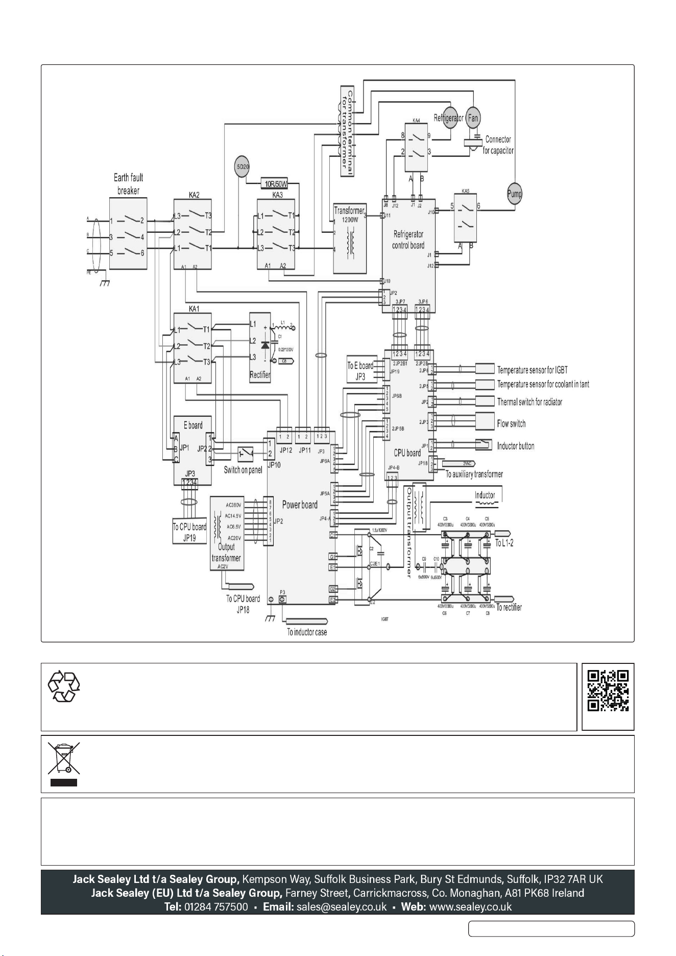
7.1. ELECTRICAL DRAWINGS
NOTE: It is our policy to continually improve products and as such we reserve the right to alter data, specications and component parts
without prior notice. Please note that other versions of this product are available. If you require documentation for alternative versions, please
email or call our technical team on technical@sealey.co.uk or 01284 757505.
IMPORTANT: No Liability is accepted for incorrect use of this product.
WARRANTY: Guarantee is 12 months from purchase date, proof of which is required for any claim.
ENVIRONMENT PROTECTION
Recycle unwanted materials instead of disposing of them as waste. All tools, accessories and packaging should be
sorted, taken to a recycling centre and disposed of in a manner which is compatible with the environment. When
the product becomes completely unserviceable and requires disposal, drain any uids (if applicable) into approved
containers and dispose of the product and uids according to local regulations.
REGISTER YOUR
PURCHASE HERE
WEEE REGULATIONS
Dispose of this product at the end of its working life in compliance with the EU Directive on Waste Electrical and Electronic Equipment
(WEEE). When the product is no longer required, it must be disposed of in an environmentally protective way. Contact your local solid
waste authority for recycling information.
VS290 Issue 2 19/05/2025
Original Language Version
© Jack Sealey Limited