Air conditioner
• Thank you for purchasing this Samsung air conditioner.
• Before operating this unit, please read this manual carefully and retain it for future reference.
Cover_GREE_AFRICA.indd 1 2019-10-25 오후 3:14:38
User manual/Installation manual
AR**B*HGAWK***

Content
Operation Notices
Precautions............................................................................................................1
Parts Name............................................................................................................6
Screen Operation Guide
Buttons on remote controller .................................................................................7
Introduction for icons on display screen ................................................................7
Introduction for buttons on remote controller .........................................................8
Function introduction for combination buttons .....................................................10
Maintenance
Cleaning and Maintenance..................................................................................11
Check items before maintenance........................................................................12
Installation Notice
Installation dimension diagram ............................................................................13
Selection of installation location ..........................................................................14
Requirements for electrical connection ...............................................................14
Safety precautions for installing and relocating the unit ......................................13
Accessories..........................................................................................................15
Installation
Installation of indoor unit......................................................................................16
Installation of outdoor unit ...................................................................................19
Test and operation
Test operation ......................................................................................................21
Attachment
.........................................................................22
Pipe expanding method
Configuration of connection pipe
.......................................................................................22
Tools for installation ............................................................................................13
Air switch capacity ...............................................................................................14
Explanation of Symbols
WARNING
CAUTION
NOTICE
1.Damage the product due to improper use or misuse of the product;
2.Alter, change, maintain or use the product with other equipment without abiding
by the instruction manual of manufacturer;
3.After verification, the defect of product is directly caused by corrosive gas;
4.After verification, the defects are due to improper handling during transportation
of product;
5.Operate, repair, maintain the unit without abiding by instruction manual or related
regulations;
6.After verification, the problem or dispute is caused by the quality specification or
performance of parts and components that produced by other manufacturers;
7.The damage is caused by natural calamities, unsuitable installation
environment or force majeure.
Exception Clauses
Manufacturer will bear no responsibilities when personal injury or property loss is
caused by the following reasons.
This symbol indicates the possibility of death or serious injury.
This symbol indicates the possibility of injury or damage to
property.
Indicates important but not hazard-related
information, used
to indicate risk of property damage.
Installation of the air conditioner, move or maintain the air conditioner, please
contact dealer or local service center to conduct an inspection first. Air
conditioner must be installed, moved or maintained by appointed installer/
contractor. Otherwise, it may cause serious damage or personal injury or death.
When refrigerant leaks or requires discharge during installation, maintenance, or
disassembly, it should be handled by certified professionals or otherwise in
compliance with local laws and regulations.
This appliance is not intended for use by persons (including children) with
reduced physical, sensory or mental capabilities or lack of experience and
knowledge, unless they have been given supervision or instruction concerning
use of the appliance by a person responsible for their safety.
Children should be supervised to ensure that they do not play with the appliance.
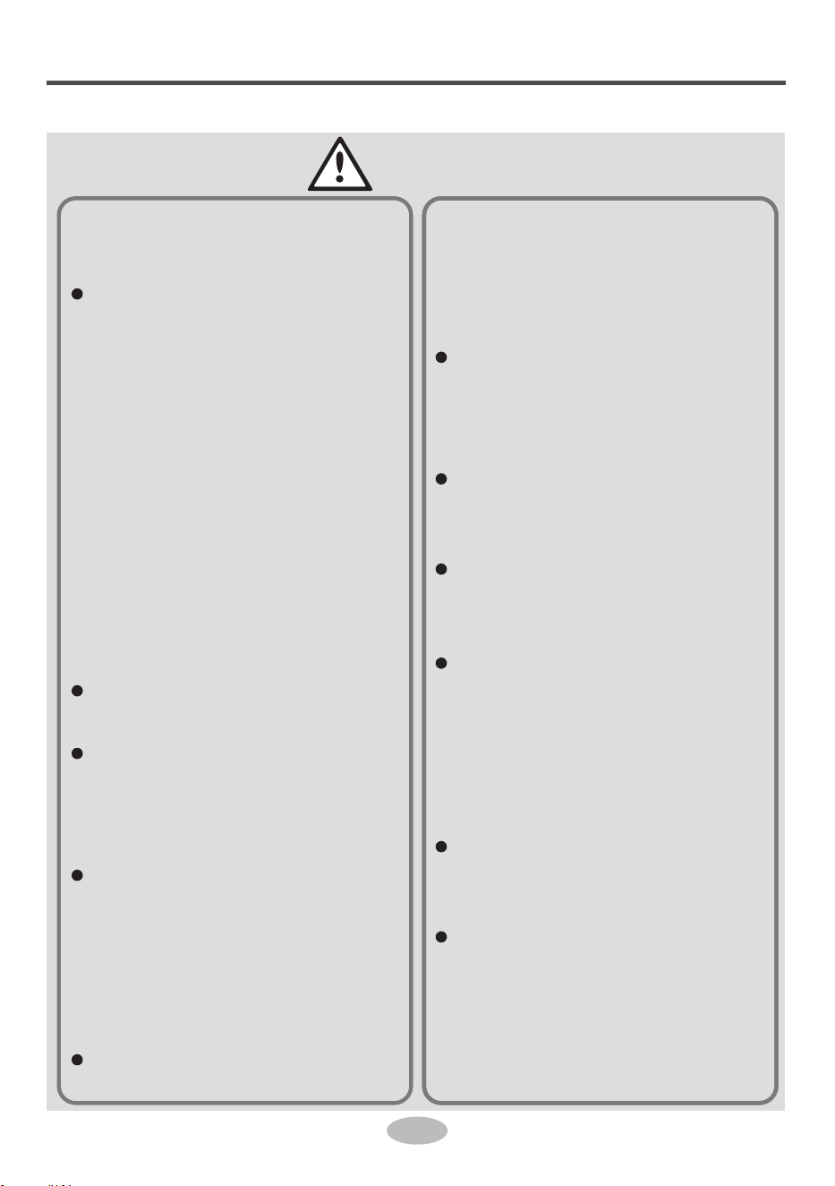
Safety precautions
Installation
1
WARNING
Installation or maintenance
must be performed by qua-
lified professionals.
The appliance shall be in-
stalled in accordance with
national wiring regulations.
According to the local safe-
ty regulations, use quali-
fied power supply circuit
and circuit breaker.
All wires of indoor unit and
outdoor unit should be con-
nected by a professional.
Be sure to cut off the power
supply before proceeding
any work related to elec-
tricity and safety.
Make sure the power supp-
ly matches with the require-
ment of air conditioner.
Unstable power supply or
incorrect wiring may result
in electric shock, fire haza-
rd or malfunction. Please
install proper power supply
cables before using the air
conditioner.
The grounding resistance
should comply with nation-
al electric safety regula-
tions.
Air Conditioner should be
properly grounded. Inco-
rrect grounding may cause
electric shock.
Do not put through the
power before finishing in-
stallation.
Do install the circuit brea-
ker. If not, it may cause
malfunction.
An all-pole disconnection
switch having a contact se-
paration of at least 3mm in
all poles should be conne-
cted in fixed wiring.
Circuit breaker should be
included magnet buckle
and heating buckle func-
tion. It can protect the
overload and circuit-short.
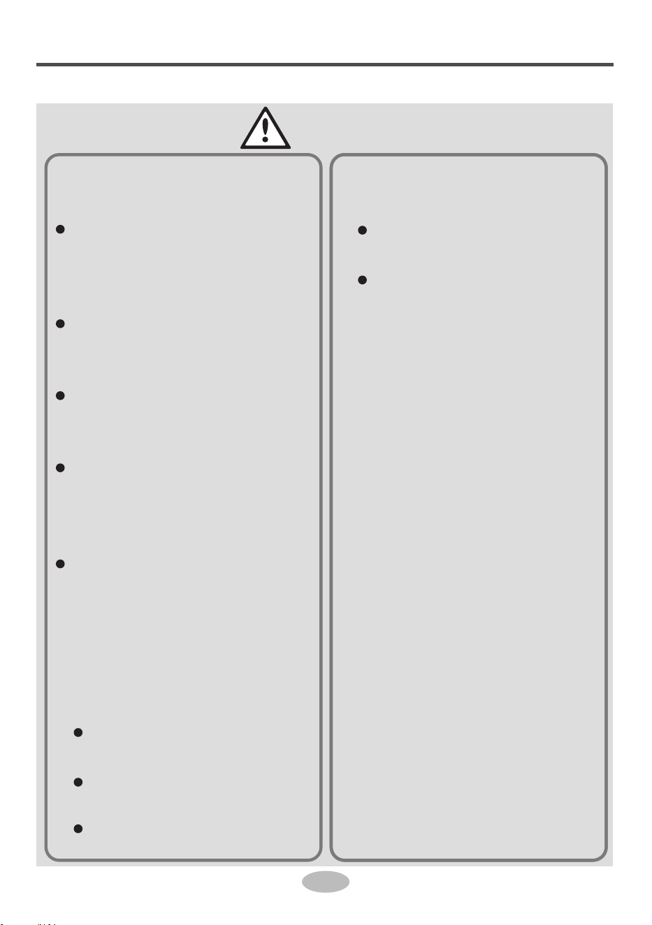
Safety precautions
Installation
2
CAUTION
Instructions for installation
and use of this product are
provided by the manufac-
turer.
Select a location which is
out of reach for children
and far away from animals
or plants. If it is unavoid-
able, please add the fence
for safety purpose.
The indoor unit should be
installed close to the wall.
Don't use unqualified pow-
er cord.
If the length of power con-
nection wire is insufficient,
please contact the supplier
for a new one.
The appliance must be po-
sitioned so that the plug is
accessible.
For the air conditioner with
plug, the plug should be re-
achable after finishing in-
stallation.
For the air conditioner with-
out plug, a circuit breaker
must be installed in the
line.
The yellow-green wire in
air conditioner is ground-
ing wire, which can't be us-
ed for other purposes.
The air conditioner is the
first class electric applian-
ce. It must be properly gro-
under with specialized gr-
ounding device by a pro-
fessional. Please make
sure it is always ground-
ed effectively, otherwise it
may cause electric shock.
The temperature of refri-
gerant circuit will be high,
please keep the interconn-
ection cable away from the
copper tube.
Safety precautions
Operation
and Maintenance
3
WARNING
This appliance can be used
by children aged from 8
years and above and per-
sons with reduced physi-
cal, sensory or mental ca-
pabilities or lack of expe-
rience and knowledge if
they have been given su-
pervision or instruction con-
cerning use of the applian-
ce in a safe way and un-
derstand the hazards in-
volved.
Children shall not play with
the appliance.
Cleaning and user main-
tenance shall not be made
by children without super-
vision.
If the supply cord is damag-
ed, it must be replaced by
the manufacturer, its ser-
vice agent or similarly qua-
lified persons in order to
avoid a hazard.
Do not connect air condi-
tioner to multi-purpose soc-
ket. Otherwise, it may cau-
se fire hazard.
Do disconnect power supp-
ly when cleaning air condi-
tioner. Otherwise, it may
cause electric shock.
Do not wash the air condi-
tioner with water to avoid
electric shock.
Do not spray water on in-
door unit. It may cause ele-
ctric shock or malfunction.
Do not repair air condition-
er by yourself. It may cause
electric shock or damage.
Please contact dealer when
you need to repair air con-
ditioner.
After removing the filter, do
not touch fins to avoid in-
jury.
Do not extend fingers or
objects into air inlet or air
outlet. It may cause person-
al injury or damage.
Safety precautions
Operation
and Maintenance
4
CAUTION
Do not spill water on the re-
mote controller, otherwise
the remote controller may
be broken.
Do not use fire or hair dry-
er to dry the filter to avoid
deformation or fire hazard.
Do not block air outlet or
air inlet. It may cause mal-
function.
Do not step on top panel of
outdoor unit, or put heavy
objects. It may cause dam-
age or personal injury.
When below phenomenon
occurs, please turn off air
conditioner and disconnect
power immediately, and
then contact the dealer or
qualified professionals for
service.
Power cord is overheat-
ing or damaged.
There’s abnormal sound
during operation.
Circuit breaker trips off
frequently.
Air conditioner gives off
burning smell.
Indoor unit is leaking.
CAUTION
5
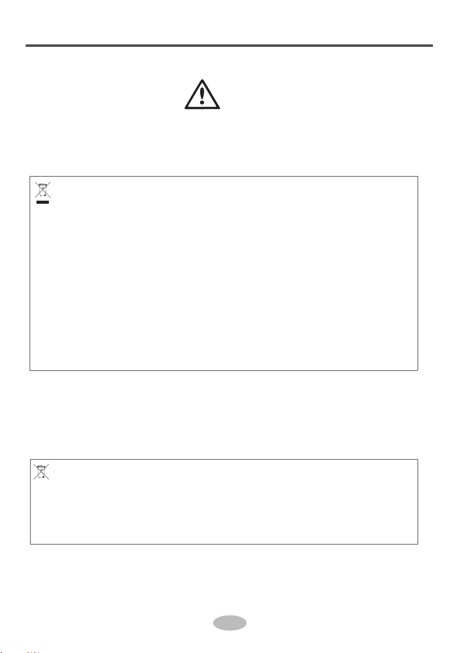
Correct disposal of batteries in this product
This marking on the battery, manual or packaging indicates that the batteries in this product should not
be disposed of with other household waste at the end of their working life. Where marked, the chemical
symbols Hg, Cd or Pb indicate that the battery contains mercury, cadmium or lead above the reference
levels in EC Directive 2006/66.
Correct Disposal of This Product
(Waste Electrical & Electronic Equipment)
(Applicable in countries with separate collection systems)
This marking on the product, accessories or literature indicates that the product and its electronic
accessories (e.g. charger, headset, USB cable) should not be disposed of with other household waste
at the end of their working life. To prevent possible harm to the environment or human health from
uncontrolled waste disposal, please separate these items from other types of waste and recycle them
responsibly to promote the sustainable reuse of material resources.
Household users should contact either the retailer where they purchased this product, or their local
government office, for details of where and how they can take these items for environmentally safe
recycling.
Business users should contact their supplier and check the terms and conditions of the purchase
contract. This product and its electronic accessories should not be mixed with other commercial wastes
for disposal.
Safety precautions
6
●
●
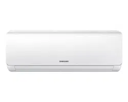
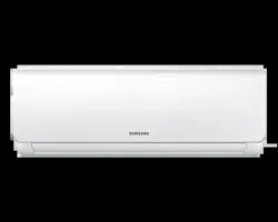
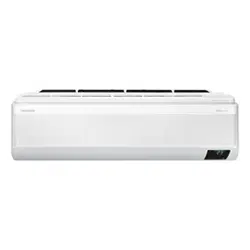
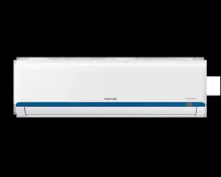
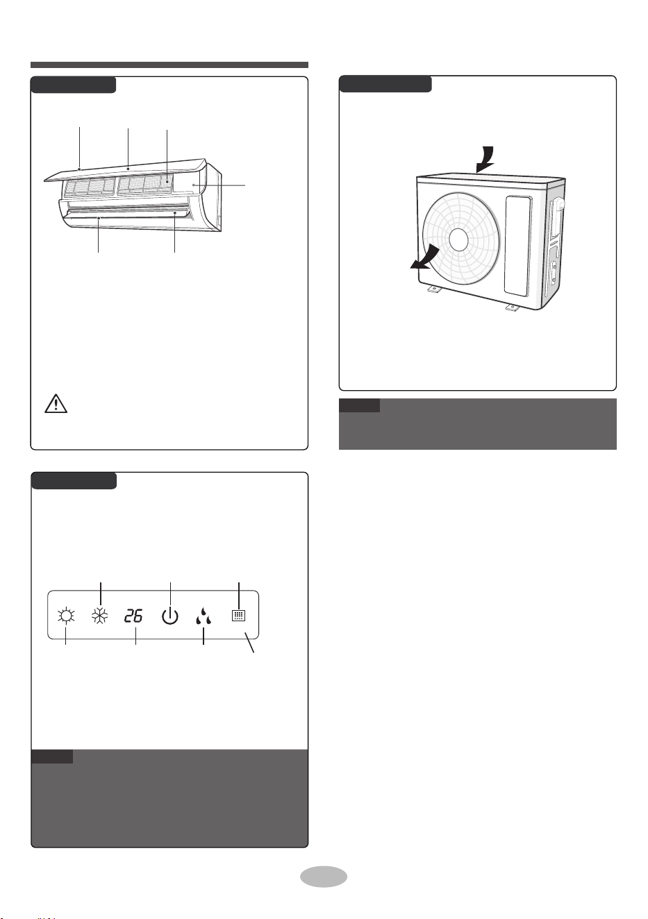
Parts name
Indoor Unit
Outdoor Unit
Display
NOTE
●
Actual product may be different from above graphics,
please refer to actual product.
This is the general introduction and the color of
indicator is only for reference. Please refer to the
actual display.
Display content may be different from the actual.
Please refer to the actual display.
NOTE
aux. button
filterair inlet panel
horizontal louver
air outlet
■
If remote controller is lost or damaged, please
use aux. button to turn on or turn off the air
conditioner. The operation in details is as
below: As shown in the figure, open panel and
press aux. button to turn off the air conditioner.
When the air conditioner is turned on, it will
operate under auto mode.
air inlet
air outlet
heating
indicator
temp.
indicator
cooling
indicator
power
indicator
receiver
window
drying
indicator
display
WARNING
Use insulated object to press the auto button

ON/OFF
MODE
X-FAN
TURBO
TEMP
TIMER OFF
SLEEP
LIGHT
FAN
CLOCK
TIMER ON
Set temperature
X-FAN function
Set temp.
temp.
Outdoor ambient
Indoor ambient
temp.
Sleep mode
Clock
Auto mode
Set time
TIMER ON / TIMER OFF
Cool mode
Dry mode
Fan mode
Light
Up & down swing
Child lock
Send signal
Turbo mode
Heat mode
Operation mode
Set fan speed
Temp.
display type
7
Introduction for icons on display
screen
Buttons on remote controller
Operation and introduction of
remote controller

●
●
button
●
●
●
●
button
AUTO COOL DRY FAN
HEAT
●
●
●
●
●
Press this button to select your required operation
mode.
●
Introduction for buttons on
remote controller
Press this button to turn on the unit. Press this button
again to turn off the unit.
8
Auto
●
●
ON/OFF
FAN
button
Press this button can set fan speed circularly as:
auto (AUTO), low ( ), medium ( ), high( ).
button
For preventing cold air, after starting up heat mode,
indoor unit will delay the fan operation for 1~5 minutes
(Actual delay time depends on indoor ambient
temperature).
Set temperature range from remote
controller:
16~30℃(61-86℉).
This mode indicator is not available for some models.
Cooling only unit won't receive heat mode signal. If
setting heat mode with remote controller, press
ON/OFF button can't start up the unit.
button
When selecting heat mode, the air conditioner
operates under heat mode. Press "+" or "-"
button to adjust set temperature. Press "FAN"
button to adjust fan speed. Press " " button
to adjust fan blowing angle.
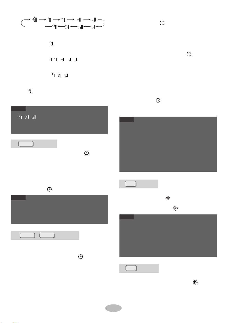
Press this button can select up & down swing
angle. Fan blow angle can be selected circularly as
below:
Under Auto speed, air conditioner will select proper
fan speed automatically according to ambient tem-
perature.
Fan speed under dry mode is low speed.
When selecting auto mode, air conditioner will
operate automatically according to ambient tem-
perature. Set temperature can't be adjusted and
will not be displayed as well. Press "FAN" button
can adjust fan speed. Press " " button can
adjust fan blowing angle.
When selecting cool mode, air conditioner will
operate under cool mode. Press "+" or "-"
button to adjust set temperature. Press "FAN"
button to adjust fan speed. Press " " button
to adjust fan blowing angle.
When selecting dry mode, the air conditioner
operates at low speed under dry mode. Under
dry mode, fan speed can't be adjusted. Press
" " button to adjust fan blowing angle.
When selecting fan mode, the air conditioner will
only blow fan, no cooling and no heating. Press
"FAN" button to adjust fan speed. Press " "
button to adjust fan blowing angle.
NOTE
NOTE
NOTE
This is a general use remote controller. It could be
used for the air conditioner with multifunction. For the
functions which the model doesn't have, if the
corresponding button
is pressed on the remote
controller, the unit will keep the original running
status.
After putting through the power, the air conditioner
will give out a sound. Power indicator " " is ON.
After that, you can operate the air conditioner by
using remote controller.
Under on status, pressing the button on the remote
controller, the signal icon " " on the display of
remote controller will blink once and the air condition-
er will give out a sound, which means the signal has
been sent to the air conditioner.
Press "+" or "-" button once increase or decrease
set temperature 1℃(℉). Holding "+" or "-" button, 2s
later, set temperature on remote controller will
change quickly. On releasing button after setting is
finished, temperature indicator on indoor unit will
change accordingly. (Temperature can’ t be adjust-
ed under auto mode)
When setting TIMER ON, TIMER OFF or CLOCK,
press "+" or "-" button to adjust time. (Refer to
CLOCK, TIMER ON, TIMER OFF buttons).
●
●
●
●
no display
(horizontal louvers
stops at current position)
●
button
●
●
●
button
“
、
、
" may not be available. When air condi-
tioner receives this signal, the air conditioner will blow
fan automatically.
●
●
●
TIMER ON button
Press "TIMER ON" to confirm it. The word "ON"
will stop blinking. " " icon resumes displaying.
Cancel TIMER ON: Under the condition that
TIMER ON is started up, press "TIMER ON"
button to cancel it.
TIMER OFF button
"TIMER OFF" button can set the time for timer
off. After pressing this button, " "icon disap-
pears and the word "OFF" on remote controller
blinks. Press Press "+" or "-" button to adjust
TIMER OFF setting. After each pressing "+" or
"-" button, TIMER OFF settin g will increase or
decrease 1min. Holding "+" or "-" button, 2s
later,
the time will change quickly until reaching
your required time.
Press "TIMER OFF" and the word "OFF" will
stop blinking. " " icon resumes displaying.
Under the condition that TIM ER OFF is started
up, press "TIMER OFF" button to cancel it.
Clock time adopts 24-hour mode.
The in terval between two operations can
't exceed 5s.
Otherwise, remote controller will q uit setting status.
Operation for TIMER ON/TIMER OFF is the same.
button/
When selectin
g " ", air conditioner is blowing
air automatically. Horizontal louver will automat-
ically swing up & down at maximum angle.
When selecting 、 、 air condition-
er is blowing air at fixed position. Horizontal
louver will stop at the fixed position.
When selecting "
、
、
", air conditioner is
blowing air at fixed angle. Horizontal louver will
send air at the fixed angle.
Hold " "button above 2s to set your required
swing angle. When reaching your required
angle, release the button.
Press this button to set clock time. " " icon on
remote controller will blink. Press "+" or "-" button
within 5s to set clock time. Each pressing of "+" or
"-" button, clock time will increase or decrease 1
minute. If hold "+" or "-" button, 2s later, time will
change quickly. Release this button when reaching
your required time. Press "CLOCK" button to
confirm the time. " " icon stops blinking.
X-FAN
CLOCK
TIMER ON
Press this button under cool and dry mode to start
up X-FAN function, and " " icon on remote control-
ler will be displayed. Press this button again to
cancel
X-FAN
function, and " " icon will disappear.
TIMER OFF
button
TURBO
When X-FAN function is on, if the air conditioner is
turned off, indoor fan will still operate at low speed
for a while to blow the residual water inside the air
duct.
During
X-FAN
operation, press X-FAN button to tur n
off
X-FAN
function. Indoor fan will stop operation
immediately.
Under cool or heat mode, press this butto n to turn
to quick cool o r quick heat mode. " " icon is
displayed on remote controller. Press this butto n
●
●
●
Under on and off status, you can set TIMER OFF or
TIMER ON simultaneously.
Before setting TIMER ON or TIMER OFF, please
adjust the clock time.
After starting up TIMER ON
or TIMER OFF, set the
constant circulating valid. After that, air conditioner
will be turned on or turned off according to setting
time. ON/OFF button has no effect on setting. If you
don 't need this function, please use remote control-
ler to cancel it.
"TIMER ON" button can set the time for timer
on. After pressing this button, " " icon disap-
pears and the word "ON" on rem ote controller
blinks. Press "+" or "-" button to adjust TIMER
ON setting. After each pressing"+" or "-" button.
TIMER ON setting will increase or decrease
1min. Holding "+" or "-" button, 2s later, the time
will change quickly until reaching your required
time.
NOTE
NOTE
NOTE
NOTE
9
●
●
●
●
Temperature display switchover function
no display
●
●
●
ambient temperature on indoor unit's display. The
setting on remote controller is selected circularly
as below:
Function introduction for
button
combination buttons
Child lock function
SLEEP
Under OFF status, press "-" and "MODE" buttons
simultaneously to switch temperature display
between
℃ and ℉.
Outdoor temperature display is not available for some
models. At that time, indoor unit receives " "
signal, while it displays indoor set temperature.
It
's defaulted to display set temperature when turning
on the unit. There is no display in the remote control-
ler.
Only for the models whose indoor unit has dual-8
display.
When selecting displaying of indoor or outdoor ambi-
ent temperature, indoor temperature indicator
displays corresponding temperature and automatical-
ly turn to display set tem
perature after three or five
seconds.
button
When selecting " " or no display with remote
controller, temperature indicator on indoor unit
displays set temperature.
When selecting " " with remote controller, tem-
perature indicator on indoor unit displays indoor
ambient temperature.
When selecting " " with remote controller,
temperature indicator on indoor unit displays
outdoor ambient temperature.
" " icon is displayed.
TEMP
button
By pressing this button, you can see indoor set tem-
perature, indoor ambient temperature or outdoor
LIGHT
again to exit turbo function and " " icon will
disappear.
Press this button to turn off display light on indoor
unit. " " icon on remote controller disappears.
Press this button again to turn on display light.
Under COOL or HEAT mode, press this button to
start up sleep function. " " icon is displayed on
remote controller. Press this button again to
cancel sleep function and " " icon will disappear.
Press "+" and "-" simultaneously to turn on or turn
off child lock function. When child lock function is
on, " " icon is displayed on remote controller. If
you operate the remote controller, the " " icon
will blink three times without sending signa
l to the
unit.
NOTE
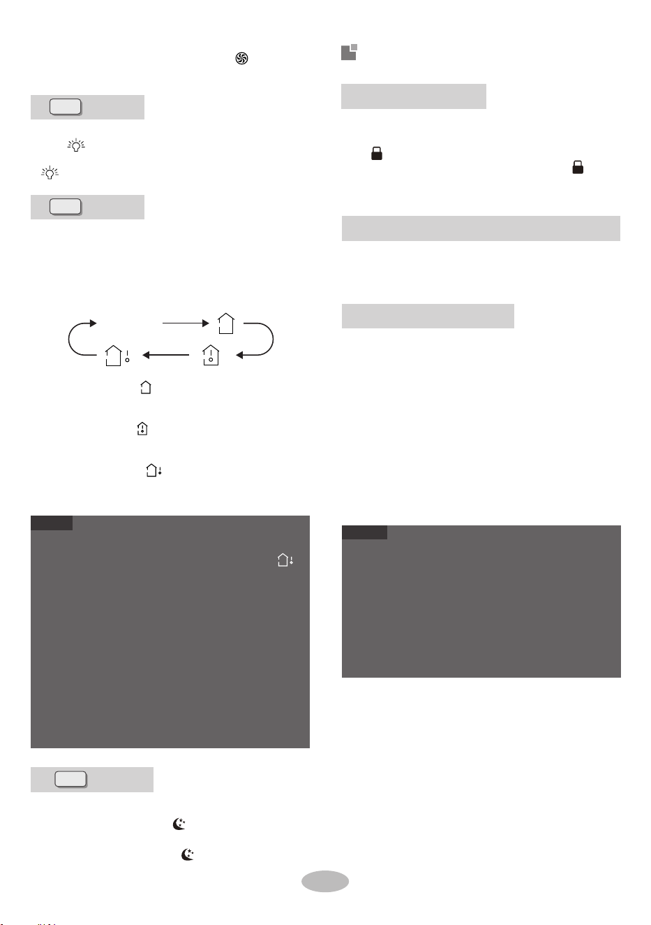
Auto clean function
●
●
NOTE
The auto clean function can only work under norm
al
ambient temperature. If the room is dusty, clean
air conditioner once a month; if not, clean air
conditioner once every three months. After the
auto clean function is turned on, you can leave the
room. When auto clean is finished, the air
conditioner will enter standby status.
This function is only available for some models.
Under unit off status, hold "MODE" and "FAN"
buttons simultaneously for 5s to turn on or turn off
the auto clean function. When the auto clean func-
tion is turned on, indoor unit displays "CL". During
the auto clean process of evaporator, the unit will
perform fast cooling or fast heating. There may be
some noise, which is the sound of flowing liquid or
thermal expansion or cold shrinkage. The air con-
ditioner may blow cool or warm air, which is a
normal phenomenon. During cleaning process,
please make sure the room is well ventilated to
avoid affecting the comfort.
10
Cleaning and maintenance
2.
■
2.
■
4.
WARNING
WARNING
■
■
■
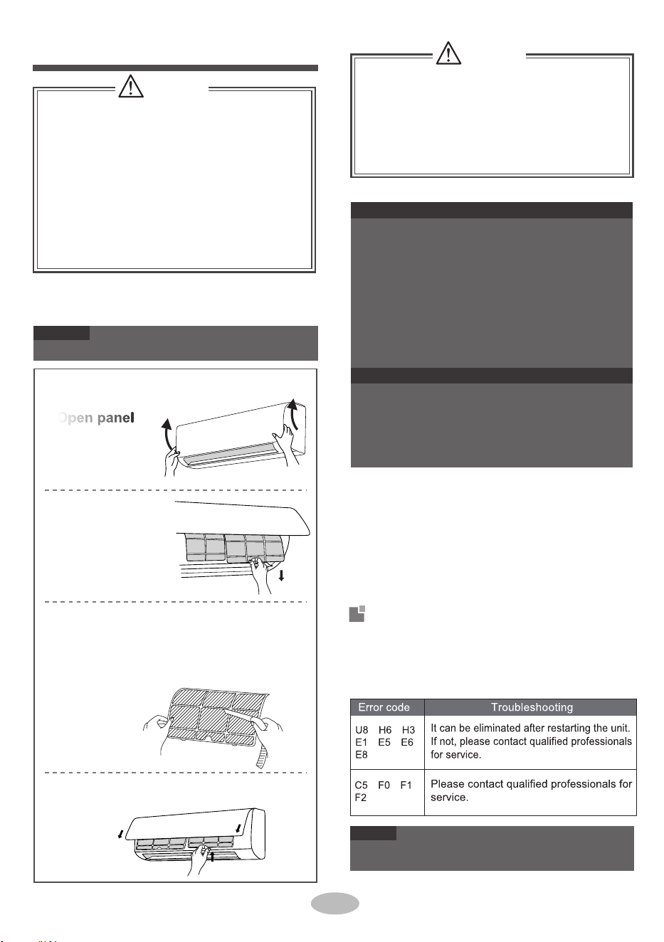
Clean filter
1.
NOTICE: Checking after use-season
Check whether air inlets and air outlets are bl-
Do not remove the panel when cleaning it.
Error Code
3.
●
●
NOTE
●
Open panel
Pull out the panel
to a certain angle
as shown in the fig.
NOTICE
●
4.
1.
1.
2.
3.
Remove filter
Remove the filter as
indicated in the fig.
NOTICE: Checking before use-season
Notice for recovery
2.
1.
Install filter
Install the filter and then close the panel cover
tightly.
If there're other error codes, please contact qu-
alified professionals for service.
Disconnect power supply.
ocked.
Check whether air switch, plug and socket are
Clean filter and indoor unit’s panel.
Clean surface of indoor unit
When the surface of indoor unit is dirty, it is recomm-
ended to use a soft dry cloth or wet cloth to wipe it.
Many packing materials are recyclable mate-
5.
Check whether drainage pipe is damaged.
Check whether mounting bracke t for outdo
or
unit is damaged or corroded. If yes, please
contact dealer.
in good condition.
3.Check whether filter is clean.
Check whether mounting bracket for outdoor
unit is damaged or corroded . If yes, please
contact dealer.
The filter should be cleaned every three months .
If there is much dust in the operation environme-
nt, clean frequency can be increased.
After removing the filter, do not touch fins to
avoid injury.
Do not use fire or hair dryer to dry the filter to
avoid deformation or fire hazard.
When air conditioner status is abnor mal, tempe-
rature indicator on indoor unit will blink to display
corresponding error code. Please refer to below
list for identification of error code.
e tairporppa ni meht esopsid esaelP .slair
recycling unit.
esaelp , renoitidnoc ria eht esopsid ot tnaw uoy fI
contact local dealer or consultant service center
for the correct disposal method.
Clean filter
Use dust catcher or water to clean the filter.
When the filter is very dirty, use the water
(below 45℃) to clean it , and then put it in a
shady and cool place to dry.
Turn off the air conditioner and disconnect the
power before cleaning the air conditioner to av-
oid electric shock.
■
Do not wash the air conditioner with water to
avoid el ectric shock.
■
Do not use volatile liquid to clean the air
conditioner.
Do not use liquid or corrosive detergent to clean
the appliance and do not splash water or other
liquid onto it , otherwise, it may damage the
plastic components , and cause electric shock.
, , ,
, , ,
, , ,
11

Checked items before
maintenance
Phenomenon Solution
Eliminate the odour
source. Clean the
filter.
Temperature can’t
be adjusted under
auto mode. Please
switch the operation
mode if you need to
adjust temperature.
Unit is operating un-
der auto mode?
Your required temp-
erature exceeds the
set temperature
range?
Whether remote co-
ntroller is within the
signal receiving range?
Voltage is too low?
Wait until the voltage
resumes normal.
Remove obstacles.
Select proper angle
and point the remote
controller at the rece-
iving window on indoor
unit.
Filter is dirty? Clean the filter.
Whether remote co-
ntroller is pointing at
the receiving window?
Adjust temperature to
proper range.
Is sensitivity of rem-
ote controller low;
fuzzy display or no
display?
Check the batteries.
If th e powe r of batteries
is to o low , please rep-
lace them.
Whether there’s inte-
rference, such as
thunder, wireless
devices, etc.
Disconnect power,
put back power, and
then turn on the unit
again.
No display when op-
erating remote cont-
roller?
Check whether rem-
ote controller appears
to be damaged. If yes,
replace it.
During defrosting
under heating mode,
it may generate vapor,
which is a normal
phenomenon.
Take the remote con-
troller close to indoor
unit. Turn off the fluo-
rescent lamp and then
try it again.
The noise is the sound
of refrigerant flowing
inside the unit, which is
a normal phenomenon.
Eliminate obstacles.
This is the sound of
friction caused by
expansion and
or
contraction of panel
or other parts due to
the change
of temp-
erature.
Under heating mode,
indoor temperature is
reached to set temp-
erature?
In order to prevent
blowing out cold air,
indoor unit will be
started after delaying
for several minutes,
which is a normal
phenomenon.
Heating mode is
turned on just now?
WARNING
When below phenomenon occurs,please turn
off air conditioner and disconnect power immedi-
ately, and then contact the dealer or qualified
professionals for service.
■
Power failure?
Is plug loose?
Reinsert the plug.
● Power cord is overheating or damaged.
There’s abnormal sound during operation.
Air switch trips off frequently.
Air conditioner gives off burning smell.
Indoor unit is leaking.
Air switch trips off
or fuse is burnt out?
Ask professional to
replace air switch or fuse.
Wiring has malfunc-
tion?
Ask professional to
replace it.
Unit has restarted
immediately after
stopping operation?
Wait for 3min, and
then turn on the unit
again.
Do not repair or refit the air conditioner by yourself.
If the air conditioner operates under abnormal
conditions, it may cause malfunction, electric
shock or fire hazard.
Whether the function
setting for remote
controller is correct?
Reset the function.
Because indoor air
is cooled rapidly.
After a while, indoor
temperature and hu-
midity will be decrease
and mist will disappe
ar.
Indoor temperature
and humidity is high?
12
Check items
Whether there’s od-
our source, such as
furniture and cigare-
tte, etc.
General phenomenon analysis
Plea se che ck bel ow ite ms before asking for
maintenance. If the malfunction still can’t be
eliminated, please contact local dealer or qualified
professionals.
Phenomenon
Odours are
emitted
Check items
Whether it's interfered
severely (such as sta-
tic electricity, stable
voltage?)
Solution
Pull out the plug.
Reinsert the plug after
about 3min, and then
turn on the unit again.
Set tempe-
rature can’t
be adjusted
Set temperature
range: 16℃~30
℃.
Signal receiving
range is 8m.
Whether there are
obstacles?
Indoor unit
can’t receive
remote co-
ntroller’s si-
gnal or remote
controller has
no action.
Cooling
(heating)
effect is
not good.
Set temperature is
in proper range?
Door and window
are open?
Close door and
window.
Air conditi-
oner operates
abnormally
Outdoor unit
has vapor
Heating mode is
turned on?
Fluorescent lamp in
room?
“Water
flowing”
noise
Air conditioner is
turned on or turned
off just now?
Air inlet or air outlet
of indoor unit is
blocked?
After
reaching to set
temperature,
indoor
unit will stop blowing
out air.
No air
emitted
from indoor
unit
Cracking
noise
Air conditioner is
turned on or turned
off just now?
Wait until power
recovery.
Air
conditioner
can’t operate
■
■
Mist is emi-
tted from
indoor unit’s
air outlet
●
●
●
●

2
2
■
■
Installation notice
■
■
■
■
7
■
12
8
3
9
4
13
To ensure safety, please be mindful of the
following precautions.
5
6
14
■
10
11
WARNING
Screw driver
Impact drill
Open-end
Pipe cutter
wrench
detector
Vacuum pump
Leakage
Pressure meter
Level meter
Please contact the local agent for installation.
Don’t use unqualified power cold.
tape
Measuring
meter
Universal
spanner
Inner hexagon
When installing the unit, make sure that co-
nnection pipe is securely connected before
the compressor starts running.
If compressor starts running when stop valve
is open and connection pipe is not yet conne-
cted, air will be sucked in and cause pressure
rise or compressor rupture, resulting in injury.
Drill bit
NOTICE
Electric wires with insufficient capacity, wrong
wire connections and insecure wire terminals
may cause electric shock or fire.
●
●
Pipe expander
Torque wrench
When installing or relocating the unit, be s-
ure to keep the refrigerant
circuit free from
air or substances other than the specified
refrigerant.
Any presence of air or other foreign substance
in the refrigerant circuit will cause
system pre-
ssure rise or compressor rupture, resulting
in injury.
When in
stalling or moving the unit, do not
charge the refrigerant which does not
comply with that on the name plate of the
air conditioner.
Otherwise, it may cause abnormal operation,
wrong action, mechanical malfunction or even
serious safety accident.
When refrigerant needs to be recovered
during relocating or repairing the unit, be
1 minute.
sure that the unit is running in cooling mode.
Then, fully close the valve at high pressure
side (liquid valve). About 30-40 seconds later,
fully close the valve at low pressure side
(gas valve), immediately stop the unit and
disconnect power. Please note that the time
for refrigerant recovery should not exceed
Tools for installation
13
Drainage pipe
Safety precautions for installing and
relocating the unit
Use the specified types of wires for electrical
connections between the indoor and outdoor
units. Firmly clamp the wires so that their te-
rminals receive no external stresses.
At least 15cm
A
At least 250cm
Spac e ceilinge to th
t least 15cm
Space to the wall
At least 15cm
Space to the wall
At least 300cm
Space to the obstruction
Space to the floor
If refrigerant recovery takes too much time,
air may be sucked in and cause pressure
rise or compressor rupture, resulting in injury.
During refrigerant recovery, make sure that
liquid valve and gas valve are fully closed
and power is disconnected before detachi-
ng the connection pipe.
If compressor starts running when stop valve
is open and connection pipe is not yet conn-
ected, air will be sucked in and cause pressure
rise or compressor rupture, resulting in injury.
Prohibit installing the unit at the place where
there may be leaked corrosive gas or flamm-
able gas.
If there is leaked gas around the unit, it may
cause explosion and other accidents.
Do not use extension cords for electrical co-
nnections. If the electric wire is not long eno-
ugh, please contact a local service center au-
thorized and ask for a proper electric wire.
Poor connections may lead to electric shock or fire.
WARNING
t
Space to the obstruction
At least 50cm
Space to the obstruction
At least 30cm
50cmAt least
Space to the obs ruction
Space to the obstruction
At least 200cm
Space to the wall
At least 30cm

14
8.
Select a location where the condensation water
2.
4.
5.
Selection of installation location
3.
Requirements for electrical connection
Air switch capacity
Indoor unit
3.
4.
Basic requirement
Installing the unit in the following places may cau-
se malfunction. If it is unavoidable, please consu-
lt the local dealer:
5.
6.
7.
laundry.
1.
2.
5.
can be dispersed easily and won't affect other
people.
Safety precaution
2.
Select a location which is out of reach for chil-
dren and far away from animals or plants. If it
is unavoidable, please add the fence for safety
purpose.
1.
5.
6.
2.
It’s not allowed to be installed on
the unstable
or motive base structure
(such as truck) or in
the corrosive environment (such as chemical
factory).
3.
3.
Select a location which is convenient to conne-
ct the outdoor unit and near the power socket.
Grounding requirement
Do not put through the power before finishing
4.
Make sure that the installation follows the req-
uirement of installation dimension diagram.
There should be no obstruction near air inlet
and air outlet.
4.Select a location which is out of reach for children.
Must follow the electric safety regulations w-
hen installing the unit.
2.
air emitted by the outdoor unit will not affect
neighborhood.
installation.
7.
If the supply cord is damaged, it must
be repla-
The location should be well ventilated and dry,
in which the outdoor unit won't be exposed dir-
ectly to sunlight or strong wind.
The location should be able to withstand the
weight of outdoor unit.
According to the local safety regulations, use
Outdoor unit
1.Select a location where the noise and outflow
qualified power supply circuit and air switch.
7.
8.Please try your best to keep way from fluores-
cent lamp.
The yellow-green wire in air conditioner is
grounding wire, which can't be used for other
purposes.
An all-pole disconnection switch having a co-
ntact separation of at least 3mm in all poles
should be connected in fixed wiring.
The grounding resistance should comply with
weight of indoor unit and won't increase noise
and vibration.
The appliance must be installed 2.5m above
floor.
Don't install the indoor unit right above the ele-
ctric appliance.
1.
The place with sulfureted gas.
Other places with special circumstances.
The appliance shall not be installed in the
The place with strong heat sources, vapors,
flammable or explosive gas, or volatile objects
spread in the air.
The place with high-frequency devices (such
as welding machine, medical equipment).
The place near coastal area.
The place with oil or fumes in the air.
with national wiring regulations.
8.
The temperature of refrigerant circuit will be hi-
4.Properly connect the live wire, neutral wire and
from the copper tube.
9.
The appliance shall be installed in accordance
6.
1.
T
he air conditioner is the first class
electric
3.
appliance. It must be properly grounded with
specialized grounding
device by a professional.
Please make
sure it is always grounded effecti-
vely, otherwise it may cause electric shock.
ced by the manufacturer, its
service agent or
similarly qualified
persons in order to avoid a
hazard .
national electric safety regulations.
The appliance must be positioned so tha t the
p
l
u
g is accessible.
The location should be able to withstand t he
Make sure the power supply matches with the
requirement of air conditioner.
Unstable power
supply or incorrect wiring or malfunction. Pl-
ease install proper power supply cables before
using the air
conditioner.
gh, please keep the interconnection cable away
grounding wire of power socket.
5.
Be sure to cut off the power supply
before pr-
oceeding any work related to
electricity and safety.
Including an air switch with suitable capacity,
please note the following table . Air switch sh-
ould be included magnet buckle and heating
buckle function, it can protect the circuit-short
and overload. (Caution: please do not use the
fuse only for protecting the circuit)
Air-conditioner
Air switch capacity
09K、12K
10A
18K
16A
24K
25A
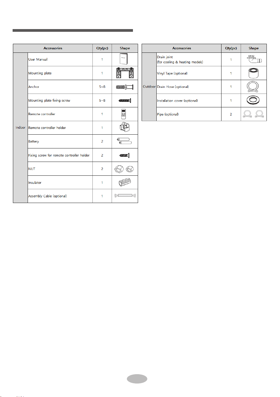
Accessories
15

Indoor outdoor
5-10
2.
rear left
3.
cut off
the hole
2.
2.
2.
3.
pipe joint union nut
pipe
3.
NOTE
●
Φ55
Install wall-mounting frame
Step 2:
Φ70
Outlet pipe
Choose installation location
Step 1:
Recommend the installation location to the client
and then confirm it with the client.
right
Step 4:
1.
Hang the wall-mounting frame on the wall; adjust
it in horizontal position with the level meter and
then point out the screw fixing holes on the wall.
Drill the screw fixing holes on the wall with im-
pact drill(the specification of drill bit should be
the same as the plastic expansion particle)
and then fill the plastic expansion particles in
the holes.
Fix the wall-mounting frame on the wall with
tapping screws and then check if the frame
is firmly installed by pulling the frame. If the
plastic expansion particle is loose, please
drill another fixing hole nearby.
Step 3:
Open piping hole
1.
Step 5:
Connect the pipe of indoor unit
Installation of indoor unit
1.
wall-mounted frame, shown as below.
Aim the pipe joint at the corresponding
NOTE
left right
left
rear right, left or rear left.
Pay attention to dust prevention
-aem ytefas tnav eler ekat dna
sures when opening the hole.
bellmouth.
Pretighten the union nut with hand.
Please refer to the actual circumstances for the
number of screws and the position of screws.
rear right
1.
15
The pipe can be led out in the direction of right,
Choose the position of piping hole according
Adjust the torque force by referring to the
wrench on the union nut. Tighten the union
nut with torque wrench.
When installation is finished, pull the mounting
plate with hand to confirm whether it is fixed
tightly. The force distribution for all screws
should be uniform.
Open a piping hole with the diameter of Φ55
or Φ70 on the selected outlet pipe position.
In order to drain smoothly, slant the piping
hole on the wall slightly downward to the
outdoor side with the gradient of 5-10°.
to the direction of outlet pipe. The position of
piping hole should be a little lower than the
When select leading out the pipe from left or
right, please cut off the corresponding hole on
the bottom case.
The wall panel is for illustrative purposes only,
please refer to the actual installation.
union nut
torque wrench
pipe
indoor pipe
open-end
wrench
following sheet. Place the open-end wren-
ch on the pipe joint and place the torque
Wall
Wall
(Rear piping hole)
(For some models)
(Rear piping hole)
Space
to the
wall
above
150mm
Left
Space
to the
wall
above
150mm
Right
Mark in the middle of it
Level meter
16
●
The plastic expansion particles are not provided.
●
4.
All wires of indoor unit and outdoor unit should be
●
If the length of power connection wire is insufficient,
Add insulating pipe in the indoor drain hose in order
to prevent condensation.
●
For the air conditioner with plug, the plug should be
●
panel
1.
drain hose
2
.
2.
outlet pipe
tape
NOTE
●
NOTICE
Step 7:
Connect wire of indoor unit
connected by a professional.
please contact the supplier for a new one. Avoid e-
xtending the wire by yourself.
reachable after finishing installation.
For the air conditioner without plug, an air switch
must be installed in the line. The air switch should
be all-pole parting and the contact parting distance
should be more than 3mm.
screw
wiring cover
cable-cross
hole
power connection
wire
Step 6:
Install drain hose
1.
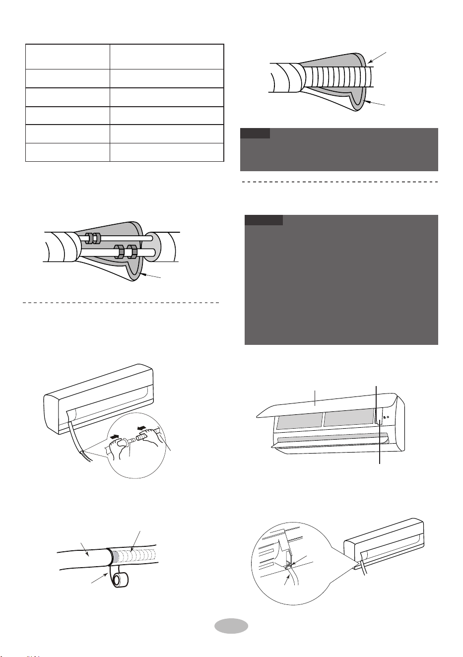
Bind the joint with tape.
indoor unit.
Wrap the indoor pipe and joint of connection
pipe with insulating pipe, and then wrap it
with tape.
insulating pipe
insulating pipe
drain hose
Open the panel, remove the screw on the wiring
cover and then take down the cover.
Connect the drain hose to the outlet pipe of
outlet
pipe
drain hose
Make the power connection wire go through the
cable-cross hole at the back of indoor unit and
then pull it out from the front side.
Hex nut diameter
1/4''
15~20
3/8''
30~40
1/2''
45~55
5/8''
60~65
3/4''
70~75
Tightening torque (N
.
m)
17
1.
5.
3.
upper hook
indoor unit
band
NOTICE
lower hook of
wall-mounting frame
The power cord and control wire can't be crossed or
winding.
The drain hose should be bound at the bottom.
2.
indoor
3.
wall pipe
4.
4.
NOTICE
outdoor
Step 9:
Hang the indoor unit
2.
sealing gum
gas
3.
4.
5.
pipe
liquid pipe
Step 8:
Bind up pipe
drain hose
1.
indoor and
outdoor power cord
NOTICE
The wiring board is for reference only, please refer
to the actual one.
Do not bend the drain hose too excessively in order
to prevent blocking.
connection pipe
drain hose
band
indoor power cord
drain hose with the band.
Put the bound pipes in the wall pipe and then
Bind up the connection pipe, power cord and
Bind them evenly.
The liquid pipe and gas pipe should be bo-
make them pass through the wall hole.
Hang the indoor unit on the wall-mounting
frame.
Stuff the gap between pipes and wall hole
with sealing gum.
Fix the wall pipe.
Check if the indoor unit is installed firmly and
closed to the wall.
und separately at the end.
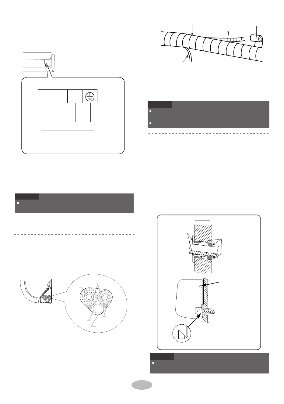
Remove the wire clip; connect the power conn-
ection wire to the wiring terminal according to
the color; tighten the screw and then fix the po-
wer connection wire with wire clip.
Put wiring cover back and then tighten the screw.
Close the panel.
green
Outdoor unit connection
N(1) 2 3
blue black brown yellow-
Reserve a certain length of drain hose and
power cord for installation when binding th-
em. When binding to a certain degree, sep-
arate the indoor power and then separate
the drain hose.
18

Place the outdoor unit on the support.
2. Fix the foot holes of outdoor unit with bolts.
foot holes
foot holes
1. Remove the screw on the right handle of out-
(select it according to the actual inst-
Step 1:
Fix the support of outdoor unit
2.
gas valve
liquid pipe
gas pipe
liquid
valve
Step 4:
Connect indoor and outdoor pipes
allation situation)
door unit and then remove the handle.
1.
1.
union nut
pipe joint
Step 3:
Fix outdoor unit
NOTICE
2.
Installation of outdoor unit
Step 2:
Install drain joint
(only for some models)
1. Connect the outdoor drain joint into the hole
NOTICE
Select installation location according to
the house structure.
Fix the support of outdoor unit on the sele-
cted location with expansion screws.
on the chassis, as shown in the picture below.
Connect the drain hose into the drain vent.
NOTE
cross-hole
As for the shape of drainage joint, please refer
to the current product. Do not install the drainage
joint in the severe cold area. Otherwise,it will be
frosted and then cause malfunction.
2. Remove the screw cap of valve and aim the
pipe joint at the bellmouth of pipe.
3.
When there're multiple cables
passing through it, the cross-hole
of handle should be knocked off
and eliminate the sharp burrs for
avoid damaging the cables.
Only applicable for some models.
Pretighten the union nut with hand.
Take sufficient protective measures when installin g
the outdoor unit.
Make sure the support can withstand at least fou r
times of the unit weight.
The outdoor unit should be installed at least
3cm above the floor in order to install drain joint.
(for the model with heating tube, the installation
height should be no less than 20cm.)
For the unit with cooling capacity of 2300W
~
5000W,
6 expansion screws are needed ; for
the unit with cooling capacity of 6000W~8000W,
8 expansion screws are needed; for the unit
with cooling capacity
of 10000W~16000W, 10
expansion screws are needed.
handle
screw
drain vent
Drain hose
chassis
outdoor drain joint
at least 3cm above the floor
19

4.
2.
1. Remove the wire clip; connect the power con-
Hex nut diameter
Tightening torque(N m)
.
wall
The drain hose can't be curved, raised
The water outlet can't be placed in water in
order to drain smoothly.
2.
1/4''
3/8''
1/2''
5/8''
3/4''
15~20
30~40
45~55
60~65
70~75
Connect outdoor electric wire
Step 5:
the drain hose
can't raise
upwards.
The water outlet
can't be placed
Slant the drain hose slightly downwards.
The drain hose can't be curved, raised and
fluctuant, etc.
in water
nection wire and signal control wire (only for
cooling and heating unit) to the wiring terminal
according to the color; fix them with screws.
The drain hose
can't be curved,
raised
The water
outlet can't be
curved, raised
Fix the power connection wire and signal con-
trol wire with wire clip (only for cooling and h-
eating unit).
Step 6:
Neaten the pipes
1.
U-shaped curve
drain hose
NOTICE
NOTICE
NOTICE
Tighten the union nut with torque wrench
by referring to the sheet below.
The wiring board is for reference only, please refer
to the actual one.
The pipes should be placed along the wall, bent
If the outdoor unit is higher than the wall hole,
reasonably and hidden possibly. Min. semidiam-
eter of bending the pipe is 10cm.
After tighten the screw, pull the power cord slightly
to check if it is firm.
Never cut the power connection wire to prolong or
shorten the distance.
The through-wal height of drain hose shoul
not be higher than the outlet pipe hole of in-
door unit.
you must set a U-shaped curve in the pipe
before pipe goes into the room, in order to
prevent rain from getting into the room.
Indoor unit connection
N(1) 2 3
blue black brown
yellow-
green
20
Test operation
Test and operation
1.
●
●
Preparation of test operation
The client approves the air conditioner.
Specify the important notes for air conditioner to
the client.
6.
Leakage detection
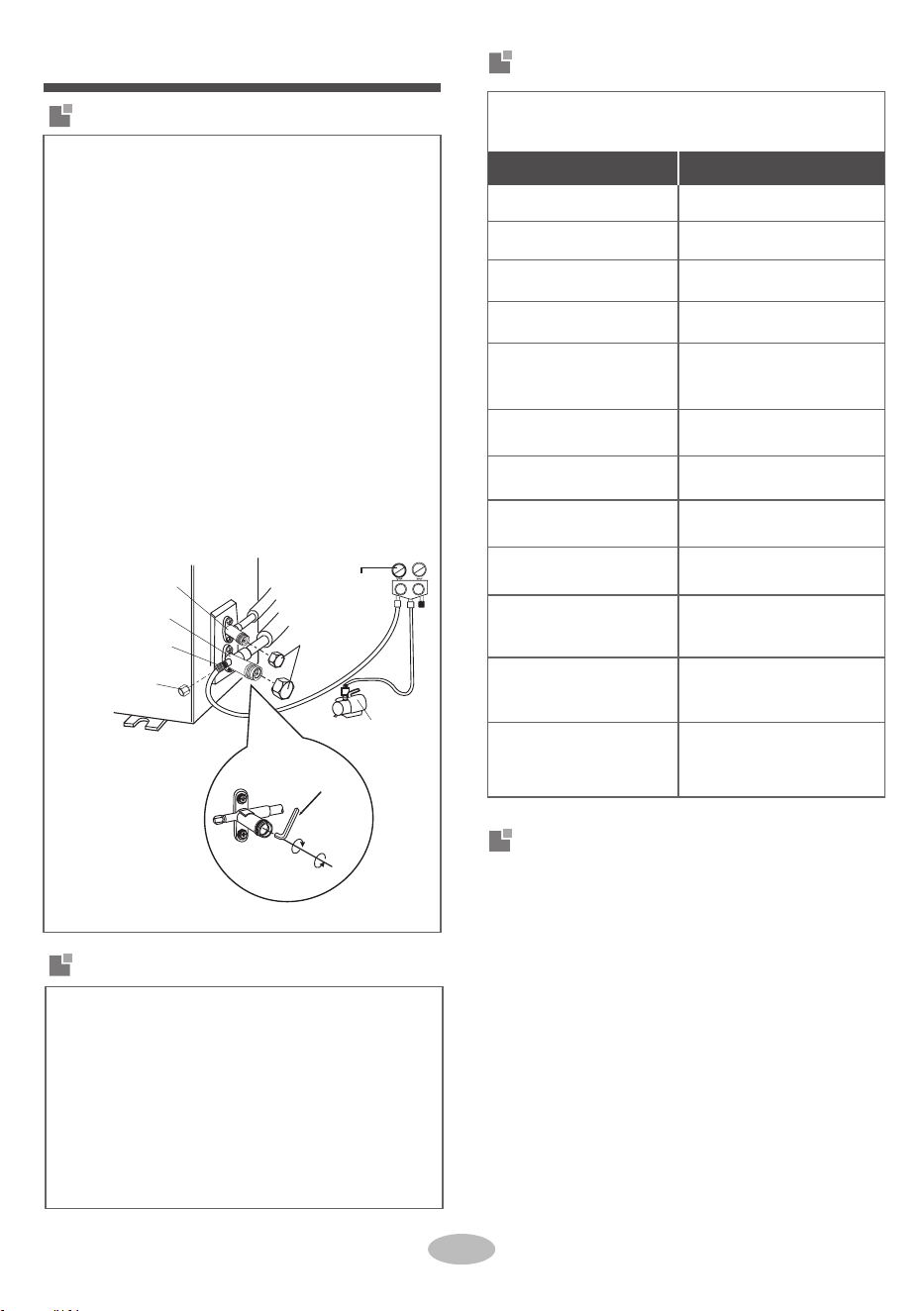
Use vacuum pump
Tighten the screw caps of valves and refriger-
1.
2.
5.
ant charging vent.
1.
Reinstall the handle.7.
tus for 1-2min to check if the pressure of piezo-
meter remains in -0.1MPa. If the pressure de-
creases, there may be leakage.
Remove the piezometer, open the valve core
of liquid valve and gas valve completely with
inner hexagon spanner.
piezometer
valve cap
liquid valve
Lo Hi
gas valve
refrigerant charging
vent
nut of refrigerant
charging vent
close
open
vacuum pump
inner hexagon
spanner
for 10-15min to check if the pressure of piezo-
meter remains in -0.1MPa.
4. Close the vacuum pump and maintain this sta-
21
2.
3.
Open the piezometer completely and operate
Remove the valve caps on the liquid valve and
refrigerant charging vent of gas valve and then
connect the other charging hose to the vacuum
pump.
With leakage detector:
Check if there is leakage with leakage detector.
With soap water:
If leakage detector is not available, please use
soap water for leakage detection. Apply soap
water at the suspected position and keep the
soap water for more than 3min. If there are air
bubbles coming out of this position, there's a
leakage.
gas valve and the nut of refrigerant charging vent.
Check after installation
● Check according to the following requirement
after finishing installation.
Possible malfunction
The unit may drop, shake or
emit noise.
Connect the charging hose of piezometer to the
Is water drained well?
It may cause condensation
and water dripping.
Items to be checked
Has the unit been
installed firmly?
Have you done the refri-
gerant leakage test?
It may cause malfunction or
damage the parts.
Is electric wiring and pip-
eline installed correctly?
It may cause malfunction or
damage the parts.
Is the unit grounded
securely?
Does the power cord fol-
low the specification?
It may cause malfunction or
damage the parts.
Is there any obstruction in
the air inlet and outlet?
It may cause insufficient
cooling(heating) capacity.
It may cause malfunction or
damage the parts.
The gas valve and liquid
valve of connection pipe
are open completely?
The dust and sundries
caused during installation
are removed?
Is heat insulation of pipe-
line sufficient?
It may cause condensation
and water dripping.
It may cause electric leakage.
Is the inlet and outlet of
piping hole been covered?
Is the voltage of power
supply according to the
voltage marked on the
nameplate?
It may cause insuffi
cient
cooling(heating) capacity.
It may cause insufficient
cooling (heating) capacity.
It may cause insufficient
cooling (heating) capacity
or waste electricity.
Method of test operation
Put through the power, pres
s " ON/OFF " button on
the remote controller to start operation.
Press MODE button to select AUTO, COOL, DRY ,
FAN and HEAT to check whether the operation i s
normal or not.
If the ambient temperature is lower than 16℃, th e
air conditioner can’t start cooling.
●
●
2.
●
22
1.
15
15
15
20
25
Max. length of
connection pipe(m)
25
30
30
30
30
Max. length of connection pipe
Pipe expanding method
Cooling capacity
5000Btu/h (1465W)
7000Btu/h (2051W)
9000Btu/h (2637W)
12000Btu/h (3516W)
18000Btu/h (5274W)
24000Btu/h (7032W)
28000Btu/h (8204W)
36000Btu/h (10548W)
42000Btu/h (12306W)
48000Btu/h (14064W)
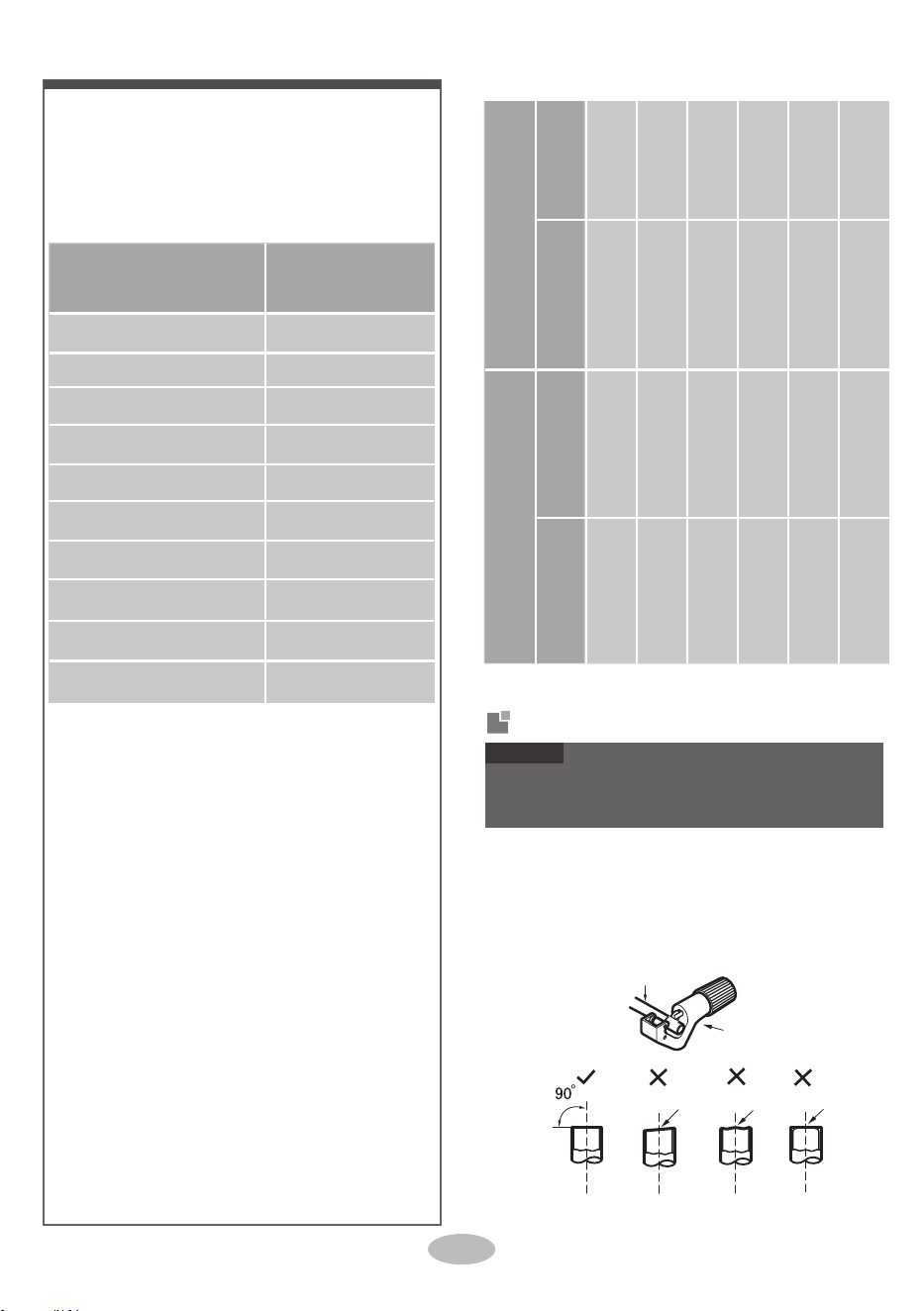
pipe cutter
pipe
●
A: Cut the pipe
2.
●
3.
leaning
uneven burr
Configuration of connection pipe
Standard length of connection pipe: 5m, 7.5m,
4.
The additional refrigerant oil and refrigerant charg-
ing required after prolonging connection pipe.
8m.
Min. length of connection pipe is 3m.
Max. length of connection pipe is shown as below.
After the length of connection pipe is prolonged
for 10m at the basis of standard length, you should
add 5ml of refrigerant oil for each additional 5m
of connection pipe.
The calculation method of additional refrigerant
charging amount(on the basis of liquid pipe):
Additional refrigerant charging amount =
prolonged length of liquid pipe × additional
refrigerant charging amount per meter
Confirm the pipe length according to the distance
of indoor unit and outdoor unit.
Cut the required pipe with pipe cutter.
Basing on the length of standard pipe, add re-
frigerant according to the requirement as shown
in the table. The additional refrigerant charging
amount per meter is different according to the
diameter of liquid pipe. See the following sheet.
15
Additional refrigerant charging amount for R22,
R407C, R410A and R134a
20
15
50
30
NOTICE
Improper pipe expanding is the main cause of refriger-
ant leakage. Please expand the pipe according to the
following steps:
120
60
120
250 250
350 350
Gas pipe
3/8'' or 1/2''
5/8'' or 3/4''
3/4'' or 7/8''
1'' or 1 1/4''
_
_
Piping size
Liquid pipe
heating(g/m)
1/4''
Outdoor unit throttle
Cooling only(g/m)
Cooling and
●
●
●
1/4'' or 3/8''
1/2''
5/8''
3/4''
7/8''

burrs from getting into the pipe.
pipe and outdoor valve;
install the union nut on
the pipe.
Remove the burrs with shaper and prevent the
the length is equal
Working temperature range
union pipe
pipe
23
Remove the union nut on the indoor connection
C: Put on suitable insulating pipe
Expand the port with expander.
smooth surface
improper expanding
uneven
thickness
leaning
damaged
crack
surface
Check the quality of expanding port. If there is
expander
pipe
hard
mold
NOTICE
●
●
B: Remove the burrs
D: Put on the union nut
●
●
E: Expand the port
●
F: Inspection
any blemish, expand the port again according to
the steps above.
shaper
downwards
pipe
A(mm)
Max Min
Φ6 - 6.35(1/4")
1.3 0.7
1.6 1.0Φ9 - 9.52(3/8")
Φ12-12.7(1/2")
1.8 1.0
Φ15.8-16(5/8")
2.4 2.2
Outer diameter
(mm)
"A" is different according to the diameter, please refer
to the sheet below:
32/23 48/26
27/- 24/18
The operating temperature range (outdoor tem -
DB/WB(°C)
Indoor side
DB/WB(°C)
Outdoor side
Maximum
cooling
Maximum
NOTE
●
perature) for cooling only
unit is 18
°C
~48
°C
;for
heat pump unit is -7
°C
~48
°C
.
heating
32/23 43/26
27/- 24/18
The operating temperature range (outdoor tem -
DB/WB(°C)
Indoor side
DB/WB(°C)
Outdoor side
Maximum
cooling
Maximum
NOTE
●
perature) for cooling only
unit is 18
°C
~43
°C
;for
heat pump unit is -7
°C
~43
°C
.
heating
09K.12K.18K.24K SA inverter:
09K.12K.18K.24K AF inverter:

COUNTRY CALL OR VISIT US ONLINE AT
SOUTH AFRICA 0860 SAMSUNG (726 7864) www.samsung.com/za/support
NAMIBIA 08 197 267 864
www.samsung.com/africa_en/support
ZAMBIA
3434
MAURITIUS
800 5050
NIGERIA 0800 726 7864
GHANA 0800 100 077
KENYA 0800 545 545
UGANDA 0800 300 300
TANZANIA 0800 780 089
REUNION 0262 50 88 80
www.samsung.com/africa_fr/support
Cote D’Ivoire 8000 0077
SENEGAL 800 00 0077
CAMEROON 67095 0077
MOZAMBIQUE 84 726 7864 www.samsung.com/africa_pt/support
SUDAN 1969 www.samsung.com/eg/support
QUESTIONS OR COMMENTS?
Cover_GREE_AFRICA.indd 2 2019-10-25 오후 3:14:38
66139903397
CLIMATISEUR
• Merci d'avoir acheté ce climatiseur Samsung.
• Avant d'utiliser cette unité, veuillez lire attentivement ce manuel et le conserver pour toute référence future.
Cover_GREE_AFRICA.indd 1 2019-10-25 오후 3:14:38
AR**B*HGAWK***
Manuel d'utilisation/Manuel d'installation

Contenu
Avis d'opération
Consignes.........................................................................................................................1
Nom des pièces ................................................................................................................6
Guide d'utilisation de l'écran
Boutons de la télécommande ...........................................................................................7
Présentation des icônes sur l'écran d'affichage ................................................................7
Présentation des boutons de la télécommande.................................................................8
Présentation des fonctions pour la combinaison des boutons........................................10
Entretien
Nettoyage et maintenance..............................................................................................11
Vérifiez les éléments avant l'entretien ...........................................................................12
Avis d'installation
Diagramme des dimensions d'installation......................................................................13
Sélection de l'emplacement d'installation ......................................................................14
Exigences pour la connexion électrique ........................................................................14
Consignes de sécurité pour l'installation et le déplacement de l'unité ...........................13
Accessoires ....................................................................................................................15
Installation
Installation de l'unité intérieure......................................................................................16
Installation de l'unité extérieure.....................................................................................19
Test et fonctionnement
Test de fonctionnement..................................................................................................21
Pièces jointes
Configuration du tuyau de raccordement.......................................................................22
Méthode de rallongement du tuyau................................................................................22
Outils pour l'installation.................................................................................................13
Capacité du commutateur d'air ......................................................................................14

Explication des Symboles
1. Le produit est endommagé en raison d'une utilisation incorrecte ou d'une mauvaise
utilisation ;
2. Modifier, changer, entretenir ou utiliser le produit avec un autre équipement sans
respecter le manuel d'instructions du fabricant ;
3. Après vérification, le défaut du produit est directement causé par un gaz corrosif ;
4. Après vérification, les défauts sont dus à une manipulation incorrecte pendant le
transport du produit ;
5. Utiliser, réparer, entretenir l'unité sans respecter le manuel d'instructions ou les
réglementations connexes ;
6. Après vérification, le problème ou le différend est causé par les spécifications de
qualité ou les performances des pièces et des composants produits par d'autres fabricants ;
7. Le dommage est causé par des calamités naturelles, un mauvais environnement
d'utilisation ou une force majeure.
Clauses de non-responsabilité
Le fabricant n'assumera aucune responsabilité lorsque des dommages corporels ou matériels
sont causés par les raisons suivantes.
Ce symbole indique la possibilité de blessures ou de dommages
matériels.
S'il est nécessaire d'installer, de déplacer ou d'entretenir le climatiseur, veuillez d'abord
contacter le revendeur ou le centre de service local pour le faire. Le climatiseur doit
être installé, déplacé ou entretenu par l'unité désignée. Dans le cas contraire, cela
pourrait causer de graves dommages ou des blessures corporelles, voire la mort.
Lorsque le réfrigérant fuit ou doit être évacué pendant l'installation, l'entretien ou le
démontage, il doit être manipulé par des professionnels certifiés ou en conformité avec
les lois et réglementations locales.
Cet appareil n'est pas destiné à être utilisé par des personnes (y compris des enfants)
dont les capacités physiques, sensorielles ou mentales sont réduites ou qui manquent
d'expérience et de connaissances, à moins qu'elles n'aient reçu une surveillance ou des
instructions concernant l'utilisation de l'appareil par une personne responsable de leur
sécurité.
Les enfants doivent être surveillés pour s'assurer qu'ils ne jouent pas avec l'appareil.
AVERTISSEMENT
MISE EN GARDE
Ce symbole indique la possibilité de blessures ou de
dommages matériels.
REMARQUE
Indique des informations importantes mais non liées au danger,
utilisées pour indiquer le risque de dommages matériels.

1
Installation or maintenance
must be performed by qua-
lified professionals.
The appliance shall be in-
stalled in accordance with
national wiring regulations.
According to the local safe-
ty regulations, use quali-
fied power supply circuit
and circuit breaker.
All wires of indoor unit and
outdoor unit should be con-
nected by a professional.
Be sure to cut off the power
supply before proceeding
any work related to elec-
tricity and safety.
Make sure the power supp-
ly matches with the require-
ment of air conditioner.
Unstable power supply or
incorrect wiring may result
in electric shock, fire haza-
rd or malfunction. Please
install proper power supply
cables befor
e using the air
conditioner.
The grounding resistance
should comply with nation-
al electric safety regula-
tions.
Air Conditioner should be
properly grounded. Inco-
rrect grounding may cause
electric shock.
Do not put through the
power before finishing in-
stallation.
Do install the circuit brea-
ker. If not, it may cause
malfunction.
An all-pole disconnection
switch having a contact se-
paration of at least 3mm in
all poles should be conne-
cted in fixed wiring.
Circuit breaker should be
included magnet buckle
and heating buckle func-
tion. It can protect the
overload and circuit-short.
Précautions de sécurité
Installation
AVERTISSEMENT
• L'installation ou l'entretien doivent être
effectués par des professionnels
qualifiés.
• L'appareil doit être installé conformé-
ment aux réglementations nationales en
matière de câblage.
• Conformément aux règles de sécurité
locales, utilisez un circuit d'alimenta-
tion et un disjoncteur qualifiés.
• Tous les fils de l'unité intérieure et de
l'unité extérieure doivent être connectés
par un professionnel.
• Installez le disjoncteur. Si ce n'est pas le
cas, cela peut provoquer un
dysfonctionnement.
• Un sectionneur omnipolaire doté d'une
séparation de contact d'au moins 3 mm
sur tous les pôles doit être connecté
dans le câblage fixe.
• Le disjoncteur doit inclure la fonction
de boucle magnétique et de boucle de
chauffage. Il peut protéger la surcharge
et le court-circuit.
• Assurez-vous de couper l'alimentation
électrique avant de procéder à tout
travail lié à l'électricité et à la sécurité.
• Assurez-vous que l'alimentation
électrique correspond aux exigences du
climatiseur.
• Une alimentation électrique instable ou
un câblage incorrect peut entraîner un
choc électrique, un risque d'incendie ou
un dysfonctionnement. Veuillez
installer les câbles d'alimentation
appropriés avant d'utiliser le climati-
seur.
• La résistance de mise à la terre doit être
conforme aux réglementations natio-
nales en matière de sécurité électrique.
• Le climatiseur doit être correctement
mis à la terre. Une mise à la terre
incorrecte peut provoquer un choc
électrique.
• Ne mettez pas l'appareil sous tension
avant de terminer l'installation.
Instructions for installation
and use of this product are
provided by the manufac-
turer.
Select a location which is
out of reach for children
and far away from animals
or plants. If it is unavoid-
able, please add the fence
for safety purpose.
The indoor unit should be
installed close to the wall.
Don't use unqualified pow-
er cord.
If the length of power con-
nection wire is insufficient,
please contact the supplier
for a new one.
The appliance must be po-
sitioned so that the plug is
accessible.
For the air conditioner with
plug, the plug should be re-
achable after finishing in-
stallation.
For the air conditioner with-
out plug, a circuit breaker
must be installed in the
line.
The yellow-green wire in
air condit
ioner is ground-
ing wire, which can't be us-
ed for other purposes.
The air conditioner is the
first class electric applian-
ce. It must be properly gro-
under with specialized gr-
ounding device by a pro-
fessional. Please make
sure it is always ground-
ed effectively, otherwise it
may cause electric shock.
The temperature of refri-
gerant circuit will be high,
please keep the interconn-
ection cable away from the
copper tube.
Précautions de sécurité
Installation
2
MISE EN GARDE
• L'unité intérieure doit être installée près
du mur.
• N'utilisez pas de cordon d'alimentation
non qualifié.
• Si la longueur du fil de raccordement
électrique est insuffisante, veuillez
contacter le fournisseur pour en obtenir
un nouveau.
L'appareil doit être positionné de telle
sorte que la prise soit accessible.
• Pour le climatiseur avec prise, la prise
doit être accessible une fois l'installa-
tion terminée.
• Les instructions d'installation et
d'utilisation de ce produit sont fournies
par le fabricant.
• Choisissez un emplacement hors de
portée des enfants et loin des animaux
ou des plantes. Si cela est inévitable,
veuillez ajouter la clôture pour des
raisons de sécurité.
• Pour le climatiseur sans prise, un
disjoncteur doit être installé sur la ligne.
• Le fil jaune-vert du climatiseur est un
fil de mise à la terre, qui ne peut pas
être utilisé à d'autres fins.
• Le climatiseur est l'appareil électrique
de première classe. Il doit être
correctement mis à la terre avec un
dispositif de mise à la terre spécialisé
par un professionnel. Assurez-vous qu'il
est toujours correctement mis à la terre,
sinon cela peut provoquer un choc
électrique.
• La température du circuit de réfrigérant
sera élevée, veuillez éloigner le câble
d'interconnexion du tube de cuivre.

This appliance can be used
by children aged from 8
years and above and per-
sons with reduced physi-
cal, sensory or mental ca-
pabilities or lack of expe-
rience and knowledge if
they have been given su-
pervision or instruction con-
cerning use of the applian-
ce in a safe way and un-
derstand the hazards in-
volved.
Children shall not play with
the appliance.
Cleaning and user main-
tenance shall not be made
by children without super-
vision.
If the supply cord is damag-
ed, it must be replaced by
the manufacturer, its ser-
vice agent or similarly qua-
lified persons in order to
avoid a hazard.
Do not connect air condi-
tioner to multi-purpose soc-
k
et. O
therwise, it may cau-
se fire hazard.
Do disconnect power supp-
ly when cleaning air condi-
tioner. Otherwise, it may
cause electric shock.
Do not wash the air condi-
tioner with water to avoid
electric shock.
Do not spray water on in-
door unit. It may cause ele-
ctric shock or malfunction.
Do not repair air condition-
er by yourself. It may cause
electric shock or damage.
Please contact dealer when
you need to repair air con-
ditioner.
After removing the filter, do
not touch fins to avoid in-
jury.
Do not extend fingers or
objects into air inlet or air
outlet. It may cause person-
al injury or damage.
Précautions de sécurité
Opération et Maintenance
3
AVERTISSEMENT
• Les enfants ne doivent pas jouer avec
l'appareil.
• Le nettoyage et l'entretien par l'utilisa-
teur ne doivent pas être effectués par
des enfants sans surveillance.
• Si le cordon d'alimentation est endom-
magé, il doit être remplacé par le
fabricant, son agent de service ou des
personnes qualifiées similaires afin
d'éviter tout danger.
• Ne pas brancher le climatiseur sur une
prise multi-usage. Sinon, cela pourrait
provoquer un incendie.
• Débranchez l'alimentation électrique
lors du nettoyage du climatiseur. Sinon,
cela pourrait provoquer un choc
électrique.
• Ne lavez pas le climatiseur à l'eau pour
éviter tout risque de choc électrique.
• Ne pulvérisez pas d'eau sur l'unité
intérieure. Cela pourrait provoquer un
choc électrique ou un dysfonctionne-
ment.
• Cet appareil peut être utilisé par des
enfants âgés de 8 ans et plus et des
personnes ayant une déficience
physique, sensorielle ou mentale, ou
manquantes d'expérience et de connais-
sances, à moins qu'ils aient été super-
visés ou instruits concernant l'utilisation
de l'appareil d'une manière sûre et qu'ils
comprennent les dangers associés.
• Ne réparez pas le climatiseur
vous-même. Cela pourrait provoquer un
choc électrique ou des dommages
matériels. Veuillez contacter votre
revendeur lorsque vous devez réparer le
climatiseur.
• Après avoir retiré le filtre, ne touchez
pas les ailettes pour éviter les blessures.
• N'insérez pas les doigts ou des objets
dans l'entrée ou la sortie d’air. Cela
pourrait causer des blessures corpo-
relles ou des dommages matériels.

Do not spill water on the re-
mote controller, otherwise
the remote controller may
be broken.
Do not use fire or hair dry-
er to dry the filter to avoid
deformation or fire hazard.
Do not block air outlet or
air inlet. It may cause mal-
function.
Do not step on top panel of
outdoor unit, or put heavy
objects. It may cause dam-
age or personal injury.
When below phenomenon
occurs, please turn off air
conditioner and disconnect
power immediately, and
then contact the dealer or
qualified professionals for
service.
Power cord is overheat-
ing or damaged.
There’s abnormal sound
during operation.
Circuit breaker trips off
frequently.
Air conditioner giv
es off
burning smell.
Indoor unit is leaking.
Précautions de sécurité
Opération et Maintenance
4
MISE EN GARDE
• Le climatiseur dégage une odeur de
brûlé.
• L’unité intérieure fuit.
• Lorsque le phénomène ci-dessous se
produit, éteignez le climatiseur et
débranchez immédiatement l'alimenta-
tion électrique, puis contactez le
revendeur ou des professionnels
qualifiés pour le faire réparer.
• Le cordon d'alimentation surchauffe ou
est endommagé.
• Il y a un bruit anormal pendant le
fonctionnement.
• Le disjoncteur se déclenche fréquem-
ment.
• Ne renversez pas d’eau sur la télécom-
mande, sinon la télécommande pourrait
être endommagée.
• N'utilisez pas le feu ou un sèche-ch-
eveux pour sécher le filtre afin d'éviter
toute déformation ou tout risque
d'incendie.
• Ne bloquez pas la sortie ou l'entrée
d'air. Cela pourrait provoquer un
dysfonctionnement.
• Ne marchez pas sur le panneau
supérieur de l'unité extérieure et ne
posez pas d'objets lourds dessus. Cela
pourrait causer des dommages matériels
ou des blessures corporelles.

MISE EN GARDE
5
Élimination correcte des batteries dans ce produit
Ce marquage sur la batterie, le manuel ou l'emballage indique que les batteries de ce produit ne doivent pas être
jetées avec les autres déchets ménagers à la fin de leur vie utile. Une fois marqués, les symboles chimiques Hg,
Cd ou Pb indiquent que la batterie contient du mercure, du cadmium ou du plomb au-dessus des niveaux de
référence de la directive CE 2006/66.
Élimination correcte de ce produit
(Déchets d'équipements électriques et électroniques)
(Applicable dans les pays avec les systèmes de collecte séparés)
Ce marquage sur le produit, les accessoires ou la documentation indique que le produit et ses accessoires
électroniques (chargeur, casque, câble USB, par exemple) ne doivent pas être jetés avec les autres déchets
ménagers à la fin de leur vie. Pour éviter tout risque pour l'environnement ou la santé humaine d'une
élimination incontrôlée des déchets, veuillez séparer ces éléments des autres types de déchets et les recycler
de manière responsable afin de promouvoir la réutilisation durable des ressources matérielles.
Les utilisateurs domestiques doivent contacter le revendeur auprès duquel ils ont acheté ce produit ou leur bureau
gouvernemental local pour savoir où et comment ils peuvent éliminer ces éléments à des fins de recyclage
respectueux de l'environnement.
Les utilisateurs professionnels doivent contacter leur fournisseur et vérifier les termes et conditions du contrat
d'achat. Ce produit et ses accessoires électroniques ne doivent pas être mélangés avec d'autres déchets
commerciaux pour leur élimination.
Précautions de sécurité
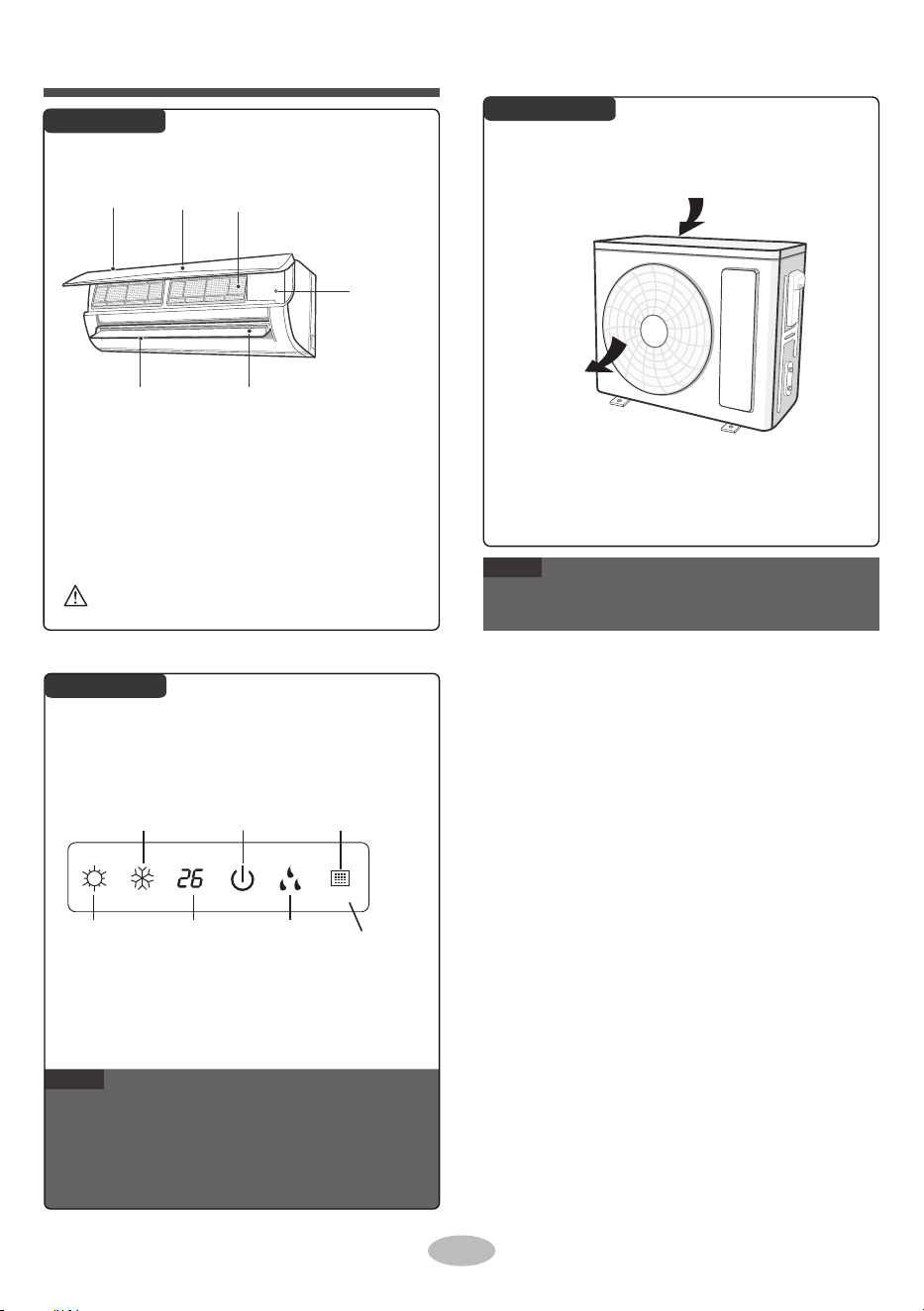
●
●
●
Actual product may be different from above graphics,
please refer to actual product.
This is the general introduction and the color of
indicator is only for reference. Please refer to the
actual display.
Display content may be different from the actual.
Please refer to the actual display.
■
If remote controller is lost or damaged, please
use aux. button to turn on or turn off the air
conditioner. The operation in details is as
below: As shown in the figure, open panel and
press aux. button to turn off the air conditioner.
When the air conditioner is turned on, it will
operate under auto mode.
6
Nom des pièces
Unité intérieure
Unité extérieure
Affichage
Remarque
Remarque
Bouton aux.
FiltrePanneauEntrée d'air
Volet horizontal
Sortie d'air
Entrée d'air
Sortie d'air
Voyant de
chauffage
Voyant de
temp.
Voyant de
refroidissement
Voyant
d'alimentation
Fenêtre du
récepteur
Voyant de
séchage
display
Le contenu affiché peut être différent du contenu réel.
Veuillez vous référer à l'affichage réel.
Si la télécommande est perdue ou endommagée, veuillez
utiliser le bouton aux. pour allumer ou éteindre le
climatiseur. L'opération en détail est la suivante : Comme
indiqué sur la figure, ouvrez le panneau et appuyez sur le
bouton aux. pour éteindre le climatiseur. Lorsque le
climatiseur est mis en marche, il fonctionne en mode
automatique.
Il s'agit d'une introduction générale et la couleur de
l'indicateur n'est qu'une référence. Veuillez vous référer à
l'affichage réel.
Le produit réel peut être différent des images ci-dessus,
veuillez vous référer au produit réel.
AVERTISSEMENT
Utilisez un objet isolé pour appuyer sur le bouton automatique

ON/OFF MODE
X-FAN
TURBO
TEMP.
TIMER OFF
VEILLE
LUMIÈRE
VENTILATEUR
HORLOGE
TIMER ON
Température définie
Fonction X-FAN
Temp. préréglée
Temp. ambiante
extérieure.
Temp. ambiante
intérieure.
Mode veille
HORLOGE
Mode Auto
Régler le temps
TIMER ON / TIMER OFF
Mode refroidissement
Mode séchage
Mode ventilateur
Lumière
Oscillation haut & bas
Verrou Enfant
Signal d'envoi
Mode turbo
Mode chauffage
Mode de fonctionnement
Vitesse du ventilateur définie
Type d'affichage
temp.
7
Présentation des icônes sur l'écran
d'affichage
Boutons de la télécommande
Fonctionnement et présentation
de la télécommande
ONOFF
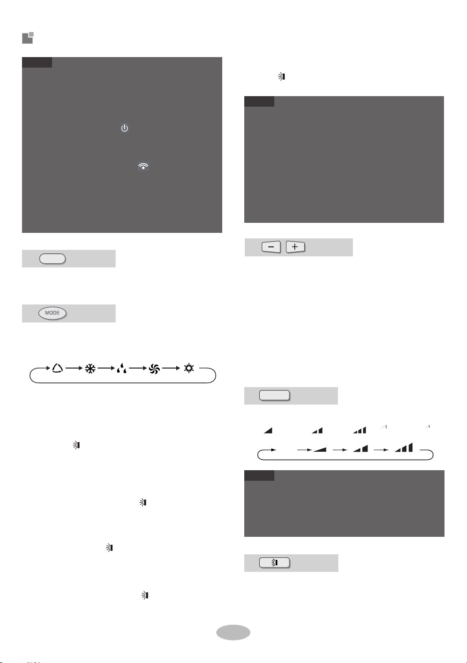
●
●
●
●
●
●
●
Press this button to turn on the unit. Press this button
again to turn off the unit.
When selecting auto mode, air conditioner will
operate automatically according to ambient tem-
perature. Set temperature can't be adjusted and
will not be displayed as well. Press "FAN" button
can adjust fan speed. Press " " button can
adjust fan blowing angle.
When selecting cool mode, air conditioner will
operate under cool mode. Press "+" or "-"
button to adjust set temperature. Press "FAN"
button to adjust fan speed. Press " nottub "
to adjust fan blowing angle.
When selecting dry mode, the air conditioner
operates at low speed under dry mode. Under
dry mode, fan speed can't be adjusted. Press
" " button to adjust fan blowing angle.
When selecting fan mode, the air conditioner will
only blow fan, no cooling and no heating. Press
"FAN" button to adjust fan speed. Press " "
button to adjust fan blowing angle.
This is a general use remote controller. It could be
used for the air conditioner with multifunction. For the
functions which the model doesn't have, if press the
corresponding b
utton on the remote controller, the
unit will keep the original running status.
After putting through the power, the air conditioner
will give out a sound. Power indicator " " is ON.
After that, you can operate the air conditioner by
using remote controller.
Under on status, pressing the button on the remote
controller, the signal icon " " on the display of
remote controller will blink once and the air condition-
er will give out a sound, which means the signal has
been sent to the air conditioner.
Press "+" or "-" button once increase or decrease
set temperature 1℃(℉). Holding "+" or "-" button, 2s
later, set temperature on remote controller will
change quickly. On releasing button after setting is
finished, temperature indicator on indoor unit will
change accordingly. (Temperature can’ t be adjust-
ed under auto mode)
When setting TIMER ON, TIMER OFF or CLOCK,
press "+" or "-" button to adjust time. (Refer to
CLOCK, TIMER ON, TIMER OFF buttons).
●
●
●
●
For preventing cold air, after starting up heat mode,
indoor unit will delay 1~5 minutes to blow air (Actual
delay time depends on indoor ambient temperature).
Set temperature range from remote controlle r:
16~30℃(61-86℉).
This mode indicator is not available for some models.
Cooling only unit won't receive heat mode signal. If
setting heat mode with remote cont roller, press
ON/OFF button can't start up the unit.
●
When selecting heat mode, the air conditioner
operates under heat mode. Press "+" or "-"
button to adjust set temperature. Press "FAN"
button to adjust fan speed. Press " " button
to adjust fan blowing angle.
bouton
bouton
CHAUFFAGE
VENTILATEUR
Auto refroidissement sec
Appuyez sur ce bouton pour sélectionner le mode
de fonctionnement souhaité.
Présentation des boutons de la
télécommande
8
AUTO
●
●
ON/OFF
VENTILATEUR
bouton
En appuyant sur ce bouton, vous pouvez régler la vitesse du
ventilateur de manière circulaire comme suit : auto (AUTO),
bas ( ), moyen ( ), haut ( ).
bouton
bouton
Appuyez sur ce bouton pour sélectionner l'angle d'oscilla-
tion vers le haut et vers le bas. L'angle de soufflage peut
être sélectionné de manière circulaire comme suit :
La vitesse du ventilateur en mode séchage est basse vitesse.
Remarque
Remarque
Remarque
Sous la vitesse automatique, le climatiseur sélectionnera
automatiquement la vitesse de ventilateur appropriée en
fonction de la température ambiante.
Appuyez une fois sur le bouton + ou - pour augmenter ou diminuer
la température préréglée par 1°C (°F). En maintenant le bouton + ou
- enfoncé pendant plus de 2 secondes, la température préréglée sur la
télécommande changera rapidement. Lorsque vous relâchez le
bouton une fois le réglage terminé, le voyant de température de
l'unité intérieure changera en conséquence. (La température ne peut
être réglée en mode automatique)
Lorsque vous réglez TIMER ON, TIMER OFF ou CLOCK, ppuyez
sur les boutons + ou - pour régler la durée. (Voir les boutons
CLOCK TIMER ON, TIMER OFF
• Pour empêcher l'air froid, après le démarrage du mode de
chauffage, l'unité intérieure retardera 1 à 5 minutes pour
souffler (le temps de retard réel dépend de la température
ambiante intérieure).
• Plage de température réglée de la télécommande : 16~30
°C
• Ce voyant n'est pas disponible sur certains modèles
• L'unité avec refroidissement seulement ne recevra pas le
signal du mode de chauffage. Si vous réglez le mode de
chauffage avec la télécommande, il est impossible de
démarrer l'unité en appuyant sur le bouton ON/OFF
• Il s'agit d'une télécommande universelle qui pourrait être
utilisée pour les climatiseurs avec multifonctions. Pour
certaines fonctions dont le modèle ne dispose pas, si vous
appuyez sur le bouton correspondant de la télécommande,
l'unité conservera son état de fonctionnement d'origine.
• Après la mise sous tension, le climatiseur émet un son. Le
voyant de fonctionnement est ALLUMÉ.
Ensuite, vous pouvez utiliser le climatiseur à l'aide de la
télécommande.
• En état allumé, en appuyant sur le bouton de la
télécommande, l'icône de signal sur l'écran de la
télécommande clignotera une fois et le climatiseur émettra
un son, ce qui signifie que le signal a été envoyé au
climatiseur.
Lorsque vous sélectionnez le mode de chauffage, le climatiseur
fonctionne en mode de chauffage. Appuyez sur le bouton + ou -
pour ajuster la température préréglée. Appuyez sur le bouton
«FAN» pour ajuster la vitesse du ventilateur. Appuyez sur le
bouton pour ajuster l'angle de soufflage du ventilateur.
• Lorsque vous sélectionnez le mode automatique, le
climatiseur fonctionnera automatiquement en fonction de la
température ambiante. La température préréglée ne peut pas
être ajustée et ne sera pas affichée également. Appuyez sur le
bouton FAN pour ajuster la vitesse du ventilateur. Appuyez
sur le bouton pour ajuster l'angle de soufflage du
ventilateur.
• Lorsque vous sélectionnez le mode refroidissement, le
climatiseur fonctionnera en mode refroidissement. Appuyez
sur le bouton + ou - pour ajuster la température préréglée.
Appuyez sur le bouton «FAN» pour ajuster la vitesse du
ventilateur. Appuyez sur le bouton pour ajuster l'angle de
soufflage du ventilateur.
• Lorsque vous sélectionnez le mode séchage, le climatiseur
fonctionne à basse vitesse en mode séchage. En mode
séchage, la vitesse du ventilateur ne peut pas être ajustée.
Appuyez sur le bouton pour ajuster l'angle de soufflage du
ventilateur.
• Lorsque vous sélectionnez le mode ventilateur, le climatiseur
ne fera que souffler, sans refroidissement ni chauffage.
Appuyez sur le bouton «FAN» pour ajuster la vitesse du
ventilateur. Appuyez sur le bouton pour ajuster l'angle de
soufflage du ventilateur.
Appuyez sur ce bouton pour allumer l'unité. Appuyez sur ce
bouton pour éteindre l'unité.

●
●
●
●
When s electing " ", air conditioner is blowing
fan automatically. Horizontal louver will automat-
ically swing up & down at maximum angle. When
selecting
、 、 " 、 、 ", air condition-er is
blowing fan at fixed position. Horizontal louver
will stop at the fixed position.
When selecting "
、
、
", air conditioner
is blowing fan at fixed angle. Horizontal louver
will send air at the fixed angle.
Hold " "button above 2s to set your required
swing angle. When reaching your required
angle, release the button.
●
“
、
、
" may not be available. When air
condi-
tioner receives this signal, the air conditioner
will blow fan automatically.
● TIMER ON button
"TIMER ON" button can set the time for timer
on. After pressing this button, " " icon disap-
pears and the word "ON" on remote controller
blinks. Press "+" or "-" button to adjust TIMER
ON setting. After each pressing"+" or "-" button.
TIMER ON setting will increase or decrease
1min. Holding "+" or "-" button, 2s later, the time
will change quickly until reaching your required
time.
●
Press "TIMER ON" to confirm it. The word "ON"
will stop blinking. " " icon resumes displaying.
Cancel TIMER ON: Under the condition that
TIMER ON is started up, press "TIMER ON"
button to cancel it.
TIMER OFF button
"TIMER OFF" button can set the time for timer
off. After pressing this button, " "icon disap-
pears and the word
"OFF" on remote controller
blinks. Press Press "+" or "-" button to adj ust
TIMER OFF setting. After each pressing "+" or
"-" button, TIMER OFF setting will increase or
decrease 1min. Holding "+" or "-" button, 2s
later, the time will change quickly until reaching
your required time.
Press "TIMER OFF" and the word "OFF" will
stop blinking. " " icon resumes displaying.
Under the condition that TIMER OFF is started
up, press "TIMER OFF" button to cancel it.
●
●
●
Under on and off status, you can set TIMER OFF or
TIMER ON simultaneously.
Before setting TIMER ON or TIMER OFF, please
adjust the clock time.
After starting up TIMER ON or TIMER OFF, set the
constant circulating valid. After that, air conditioner
will be turned on or turned off according to setting
time. ON/OFF but ton has no effect on setting. If you
don 't need this function, please use remote control-
ler to cancel it.
●
●
When X-FAN function is on, if the air conditioner is
turned off, indoor fan will still operate at low speed
for a while to blow the residual water inside the air
duct.
During
X-FAN
operation, press X-FAN button to turn
off
X-FAN
function. Indoor fan will stop operation
immediately.
aucun affichage(les volets horizontaux
s'arrêtent à la position actuelle)
bouton
bouton
bouton/
X-FAN
HORLOGE
TIMER ON
Appuyez sur ce bouton en mode refroidissement ou séchage pour
activer la fonction x-fan. L'icône de la télécommande
s'affichera. Appuyez à nouveau sur ce bouton pour annuler la
fonction de veille et l'icône disparaîtra.
TIMER OFF
TURBO
bouton
Remarque
Remarque
Remarque
Remarque
9
Appuyez sur ce bouton pour régler l'heure. L'icône « » de la
télécommande clignotera. Appuyez sur le bouton + ou - dans 5
secondes pour régler l'heure. Chaque fois que vous appuyez sur le
bouton + ou -, l'heure de l'horloge augmentera ou diminuera de 1
minute. Si vous maintenez le bouton + ou - enfoncé pendant plus de
2 secondes, l'heure changera rapidement. Relâchez ce bouton
lorsque vous arrivez à l'heure souhaitée. Appuyez sur le bouton
CLOCK pour confirmer l'heure. L'icône « » cesse de
clignoter.
L'heure de l'horloge adopte le format de 24 heures.
L'intervalle entre deux opérations ne peut pas dépasser 5
secondes. Sinon, la télécommande quittera l'état de réglage.
L'opération pour TIMER ON/TIMER OFF est identique.
En mode REFROIDISSEMENT ou CHAUFFAGE, appuyez sur
ce bouton pour passer rapidement en mode REFROIDISSE-
MENT ou CHAUFFAGE. L'icône « » est affichée surla
télécommande. Appuyez à nouveau sur ce bouton
Appuyez sur TIMER ON pour confirmer. Le mot ON cessera
de clignoter. L'icône reprend son affichage.
Pour annuler TIMER OFF : À la condition que TIMER OFF
soit activé, appuyez sur le bouton TIMER OFF pour l'annuler.
• Bouton TIMER OFF
Le bouton TIMER OFF permet de régler l'heure de
désactivation de la minuterie. Lorsque vous appuyez sur ce
bouton, l'icône disparaît et le mot OFF de la télécom-
mande clignote. Appuyez sur le bouton + ou - pour ajuster le
réglage TIMER OFF. À chaque pression sur le bouton + ou -,
le réglage TIMER OFF augmentera ou diminuera de 1 min. Si
vous maintenez le bouton + ou - enfoncé pendant plus de 2
secondes, l'heure changera rapidement jusqu'à ce que vous
arrivez à l'heure souhaitée.
Appuyez sur TIMER OFF et le mot OFF cessera de clignoter.
L'icône reprend son affichage.
À la condition que TIMER OFF soit activé, appuyez sur le
bouton TIMER OFF pour l'annuler.
• Lorsque la fonction x-fan est activée, si le climatiseur est
éteint, le ventilateur intérieur fonctionnera toujours à
basse vitesse pendant un certain temps pour chasser l'eau
résiduelle à l'intérieur du conduit d'air.
• Pendant le fonctionnement X-FAN, appuyez sur le
bouton X-FAN pour désactiver la fonction X-FAN. Le
ventilateur intérieur cessera de fonctionner immédiate-
ment
• bouton TIMER ON
Le bouton TIMER ON permet de régler l'heure d'activation de
la minuterie. Lorsquevous appuyez sur ce bouton, l'icône
disparaît et le mot ON de la télécommande clignote. Appuyez
sur le bouton + ou - pour ajuster le réglage TIMER ON. À
chaque pression sur le bouton + ou -, le réglage TIMER ON
augmentera ou diminuera de 1 min. Si vous maintenez le
bouton + ou - enfoncé pendant plus de 2 secondes, l'heure
changera rapidement jusqu'à ce que vous arrivez à l'heure
souhaitée.
• Lorsque vous sélectionnez , le climatiseur souffle
automatiquement. Les volets horizontaux pivoteront
automatiquement vers le haut et vers le bas à l'angle
maximal. Lorsque
• vous sélectionnez , le climatiseur souffle à la
position fixe. Le volet horizontal s'arrête à la position fixe.
• Lorsque vous sélectionnez , le climatiseur
souffle à angle fixe. Le déflecteur horizontal enverra de l'air à
l'angle fixe.
• Maintenez le bouton enfoncé pendant plus de 2s pour
régler l'angle d'oscillation souhaité. Lorsque vous arrivez à
l'angle souhaité, relâchez le bouton.
• En états d'activation et de désactivation, vous pouvez
activer simultanément TIMER OFF ou TIMER ON.
• Avant de régler TIMER ON ou TIMER OFF, veuillez
régler l'heure.
• Après le démarrage de TIMER ON ou de TIMER OFF,
définissez la circulation constante valide. Après cela, le
climatiseur sera allumé ou éteint en fonction du temps
défini. Le bouton ON/OFF n'a aucun effet sur le réglage.
Si vous n'avez pas besoin de cette fonction, veuillez
utiliser la télécommande pour l'annuler.
• peuvent ne pas être disponibles. Lorsque le
climatiseur reçoit ce type de signal, il soufflera
automatiquement.
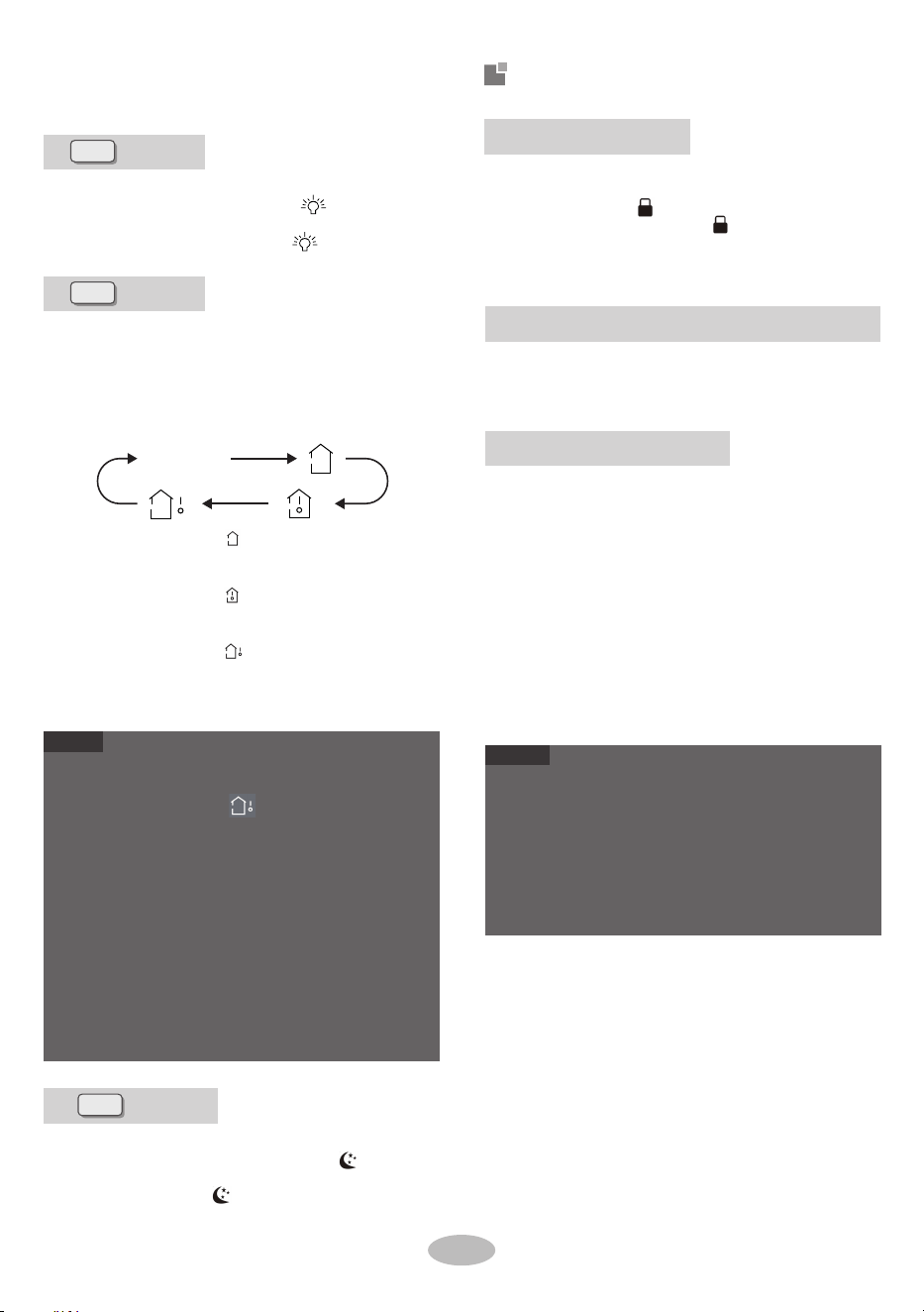
●
●
●
●
●
●
●
ambient temperature on indoor unit's display. The
setting on remote controller is selected circularly
as below:
Under OFF status, press "-" and "MODE" buttons
simultaneously to switch temperature display
between
℃ and ℉.
Outdoor temperature display is not available for some
models. At that time, indoor unit receives " "
signal, while it displays indoor set temperature.
It
's defaulted to display set temperature when turning
on the unit. There is no display in the remote control-
ler.
Only for the models whose indoor unit has dual-8
display.
When selecting displaying of indoor or outdoor ambi-
ent temperature, indoor temperature indicator
displays corresponding temperature and automatical-
ly turn to display set temperature after three or five
seconds.
When selecting " " or no display with remote
controller, temperature indicator on indoor unit
displays set temperature.
When selecting " " with remote controller, tem-
perature indicator on indoor unit displays indoor
ambient temperature.
When selecting " " with remote controller,
temperature indicator on indoor unit displays
outdoor ambient temperature.
By pressing this button, you can see indoor set tem-
perature, indoor ambient temperature or outdoor
again to exit turbo function and " " icon will
disappear.
Under COOL or HEAT mode, press this button to
start up sleep function. " " icon is displayed on
remote controller. Press this button again to
cancel sleep function and " " icon will disappear.
Press "+" and "-" simultaneously to turn on or turn
off child lock function. When child lock function is
on, " " icon is displayed on remote controller. If
you operate the
remote controller, the " " icon
will blink three times without sending signal to the
unit.
●
●
The auto clean function can only work under normal
ambient temperature. If the room is dusty, clean it
once a month; if not, clean it once every three
months. After the auto clean function is turned on,
you can leave the room. When auto clean is finished,
the air conditioner will enter standby status.
This function is only available for some models.
Under unit off status, hold "MODE" and "FAN"
buttons simultaneously for 5s to turn on or turn off
the auto clean function. When the auto clean func-
tion is turned on, indoor unit displays "CL". During
the auto clean process of evaporator, the unit will
perform fast cooling or fast heating. There may be
some noise, which is the sound of flowing liquid or
thermal expansion or cold shrinkage. The air con-
ditioner may blow cool or warm air, which is a
normal phenomenon. During cleaning process,
please make sure the room is well ventilated to
avoid affecting the comfort.
10
Fonction de commutation d'affichage de la température
aucun affichage
Présentation des fonctions pour
la combinaison des boutons
bouton
Fonction Verrou Enfant
VEILLE
bouton
TEMP.
bouton
LUMIÈRE
Appuyez sur ce bouton pour éteindre la lumière de l'écran
d'affichage de l'unité intérieure. L'icône « » de la télécom-
mande disparaît. Appuyez à nouveau sur ce bouton pour allumer la
lumière de l'écran d'affichage. L'icône « » est affichée.
Remarque
Fonction de nettoyage automatique
Remarque
En état ARRÊT, maintenez les boutons MODE et FAN enfoncés
simultanément pendant 2s pour faire activer ou désactiver la
fonction de nettoyage automatique Lorsque la fonction de nettoyage
automatique est activée, l'unité intérieure affiche CL Pendant le
processus de nettoyage automatique de l'évaporateur, l'unité
effectuera un refroidissement rapide ou un chauffage rapide. Il peut
y avoir du bruit, qui est le bruit du liquide qui coule ou d'une
dilatation thermique ou d'un retrait à froid. Le climatiseur peut
souffler de l'air froid ou chaud, ce qui est un phénomène normal.
Pendant le processus de nettoyage, assurez-vous que la pièce est
bien ventilée pour éviter d'affecter le confort.
• L'affichage de la température extérieure n'est pas
disponible sur certains modèles. Dans ce cas, si l'unité
intérieure reçoit le signal , elle affiche la température
préréglée intérieure.
• Par défaut, la température préréglée est affichée lors de la
mise en marche de l'unité. Il n'y a pas d'affichage sur la
télécommande.
• Uniquement pour les modèles dont l'unité intérieure
dispose d'un affichage dual-8.
• Lors de la sélection de l'affichage de la température
ambiante intérieure ou extérieure, le voyant de température
intérieure affiche la température correspondante et passe
automatiquement à l'affichage de la température préréglée
après trois ou cinq secondes.
En état ARRÊT, appuyez simultanément sur les boutons - et
MODE pour faire basculer l'affichage de la température entre
°C et °F.
• Lorsque vous sélectionnez ou aucun affichage avec la
télécommande, le voyant de température sur l'unité intérieure
affiche la température préréglée.
• Lorsque vous sélectionnez avec la télécommande, le voyant
de température sur l'unité intérieure affiche la température
ambiante intérieure.
• Lorsque vous sélectionnez avec la télécommande, le voyant
de température sur l'unité intérieure affiche la température
ambiante extérieure.
En appuyant sur ce bouton, vous pouvez voir la température
intérieure préréglée, la température ambiante intérieure ou la
température ambiante extérieure sur l'écran de l'unité intérieure. Le
réglage sur la télécommande est sélectionné de manière circulaire
comme suit :
• La fonction de nettoyage automatique ne peut fonctionner
qu'à une température ambiante normale. Si la pièce est
poussiéreuse, nettoyez l'unité une fois par mois ; sinon,
nettoyez-la une fois tous les trois mois. Une fois que la
fonction de nettoyage automatique est activée, vous
pouvez quitter la pièce. Lorsque le nettoyage automatique
est terminé, le climatiseur entrera en mode attente.
• Cette fonction n'est que disponible sur certains modèles
Appuyez simultanément sur + et - pour activer ou désactiver la
fonction de verrouillage enfant. Lorsque la fonction de verrouillage
enfant est activée, l'icône est affichée sur la télécommande. Si
vous utilisez la télécommande, l'icône clignotera trois fois sans
envoyer de signal à l'unité.
En mode REFROIDISSEMENT ou CHAUFFAGE, appuyez sur ce
bouton pour lancer la fonction de veille. L'icône est affichée sur la
télécommande. Appuyez à nouveau sur ce bouton pour annuler la
fonction de veille et l'icône disparaîtra.
pour quitter la fonction turbo et l'icône /disparaîtra.
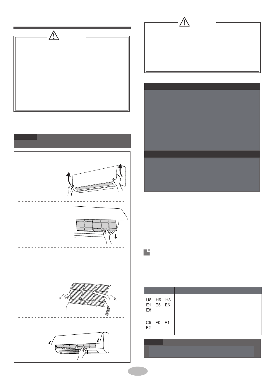
2.
■
2.
■
4.
■
■
■
1.
Check whether air inlets and air outlets are bl-
3.
●
●
●
Pull out the panel
to a certain angle
as shown in the
fig.
●
4.
1.
1.
2.
3.
Remove the filter as
indicated in the fig.
2.
1.
If there're other error codes, please contact qu-
alified professionals for service.
ocked.
Disconnect power supply.
Clean filter and indoor unit’s panel.
Clean surface of indoor unit
When the surface of indoor unit is dirty, it is
recomm-ended to use a soft dry cloth or wet cloth
to wipe it.
Many packing materials are recyclable mate-
5.Check whether drainage pipe is damaged.
Check whether mounting bracket for outdo
or
unit is damaged or corroded. If yes, please
contact dealer.
Check whether air switch, plug and socket are
in good condition.
3.Check whether filter is clean.
Check whether mounting bracket for outdoor
unit is damaged or corroded . If yes, please
contact dealer.
The filter should be cleaned every three months .
If there is much dust in the operation environme-
nt, clean frequency can be increased.
After removing the filter, do not touch fins to
avoid injury.
Do not use fire or hair dryer to dry the filter to
avoid deformation or fire hazard.
When air conditioner status is abnor mal, tempe-
rature indicator on indoor uni t will blink to display
corresponding error code. Please refer to below
list for identification of error code.
rials. Please dispose them in appropriat e
recycling unit.
If you want to dispose the air conditioner, please
contact local dealer or consultant service center
for the correct disposal method.
Use dust catcher or water to clean the
filter.
When the filter is very dirty, use the
water (below 45℃) to clean it , and then put
it in a shady and cool place to dry.
Turn off the air conditioner and disconnect the
power before cleaning the air conditioner to av-
oid electric shock.
■
Do not wash the air conditioner with water to
avoid electric shock.
■
Do not use volatile liquid to clean the air
conditioner.
Do not use liquid or corrosive detergent to clean
the appliance and do not splash water or other
liquid onto it , otherwise, it may damage the
plastic components , even cause electric shock.
, , ,
, , ,
, , ,
11
Nettoyage et maintenance
AVERTISSEMENT
AVERTISSEMENT
Nettoyez le filtre
N'enlevez pas le panneau lors du nettoyage.
Code d’erreur
Remarque
Ouvrez le panneau
REMARQUE
Retirez le filtre
Avis pour la récupération
Installez le filtre
Nettoyez le filtre
Installez le filtre puis fermez bien le couvercle du
panneau.
AVIS : Vérification avant la saison d'utilisation
AVIS : Vérification après la saison d'utilisation
• Utilisez un dépoussiéreur ou l'eau pour nettoyer
• le filtre. Lorsque le filtre est très sale, utilisez l'eau
(inférieure à 45 °C) pour le nettoyer, puis mettez-le
dans un endroit sec et frais pour le sécher.
Il peut être éliminé après le redémarrage de
l'unité. Sinon, veuillez contacter des
professionnels qualifiés pour le service.E5
Retirez le filtre comme
indiqué sur la figure.
Veuillez contacter des professionnels qualifiés
pour le service.
1 Vérifiez si les entrées et sorties d'air sont obstruées.
2. Vérifiez si le circuit, la fiche et la prise sont en bon état.
3. Vérifiez si le filtre est propre.
4. Vérifiez si le support de montage de l'unité extérieure est
endommagé ou corrodé. Si oui, veuillez contacter votre
revendeur.
5. Vérifiez si le tuyau de drainage est endommagé.
Code d’erreur
Lorsque l'état du climatiseur est anormal, le voyant de température
de l'unité intérieure clignotera pour afficher le code d'erreur
correspondant. Veuillez se reporter à la liste ci-dessous pour
identifier le code d'erreur.
■ Le filtre doit être nettoyé tous les trois mois. S'il y a
beaucoup de poussière dans l'environnement d'exploita-
tion, la fréquence de nettoyage peut être augmentée.
■ Après avoir retiré le filtre, ne touchez pas les ailettes
pour éviter les blessures.
■ N'utilisez pas le feu ou un sèche-cheveux pour sécher le
filtre afin d'éviter toute déformation ou tout risque
d'incendie.
1. Débranchez l'alimentation.
2. Nettoyez le filtre et le panneau de l'unité intérieure.
3. Vérifiez si le support de montage de l'unité extérieure est
endommagé ou corrodé. Si oui, veuillez contacter votre
revendeur.
De nombreux matériaux d'emballage sont des matériaux
recyclables. Veuillez les jeter dans un centre de recyclage
approprié.
Si vous souhaitez vous débarrasser du climatiseur, veuillez
contacter le revendeur local ou le centre de service pour la
manière d'élimination appropriée.
S'il existe d'autres codes d'erreur, veuillez contacter des
professionnels qualifiés pour le service.
Dépannage
Nettoyage de la surface de l'unité intérieure
Lorsque la surface de l'unité intérieure est sale, il est
recommandé de l'essuyer avec un chiffon doux et sec ou un
chiffon humide.
Tirez le panneau à un
certain angle, comme
indiqué sur la figure.
■ Éteignez le climatiseur et débranchez-le avant de le
nettoyer pour éviter tout risque de choc électrique.
■ Ne lavez pas le climatiseur à l'eau pour éviter tout risque
de choc électrique.
■ N'utilisez pas de liquide volatil pour nettoyer le
climatiseur.
■ N'utilisez pas de détergent liquide ou corrosif pour
nettoyer l'appareil et ne projetez pas d'eau ou tout autre
liquide dessus, sinon vous risqueriez d'endommager les
composants en plastique, voire de provoquer un choc
électrique.

Whether remote co-
ntroller is within the
signal receiving range?
Select proper angle
and point the remote
controller at the rece-
iving window on indoor
unit.
Whether remote co-
ntroller is pointing at
the receiving window?
Check the batteries.
seirettab for ewope ht fI
is to o low , please rep-
lace them.
it ma or,
.
When below phenomenon occurs,please turn
off air conditioner and disconnect power immedi-
ately, and then contact the dealer or qualified
professionals for service.
■
● Power cord is overheating or damaged.
There’s abnormal sound during operation.
Air switch trips off frequently.
Air conditioner gives off burning smell.
Indoor unit is leaking.
Ask professional to
replace air switch or fuse.
Ask professional to
replace it.
Do not repair or refit the air conditioner by yourself.
If the air conditioner operates under abnormal
conditions, it may cause malfunction, electric
shock or fire hazard.
Because indoor air
is cooled rapidly.
After a while, indoor
temperature and hu-
midity will be decrease
and mist will disappe
ar.
12
Odours are
emitted
Whether it's interfered
severely (such as sta-
tic electricity, stable
voltage?)
Set tempe-
rature can’t
be adjusted
Indoor unit
can’t receive
remote co-
ntroller’s si-
gnal or remote
controller has
no action.
Cooling
(heating)
effect is
not good.
Air
conditi-
oner operates
abnormally
Outdoor unit
has vapor
“Water
flowing”
noise
After
reaching to set
temperature,
indoor
unit will stop blowing
out air.
No air
emitted
from indoor
unit
Cracking
noise
Wait until power
recovery.
Air
conditioner
can’t operate
■
■
Mist is emi-
tted from
indoor unit’s
air outlet
●
●
●
●
Whe inte-
devi
ther there’s
rference, such as
thunder, wireless
ces, etc.
The nd
of refriger
in
a normal on
noise is the sou
ant flowing
side the unit, which is
phenomen
Pull out the plug.
Reinsert the plug after
about 3min, and then
turn on the unit again.
During defrosting
under heating mode,
y generate vap
which is a normal
phenomenon.
This is the sound of
friction caused by
expansion and
or
contraction of panel
or other parts due to
the change
of temp-
erature.
Éliminer la source d'odeur.
Nettoyez le filtre.
La température ne peut pas être
ajustée en mode automatique.
Veuillez changer le mode de
fonctionnement si vous avez
besoin de régler la température.
L'unité fonctionne-t-elle en
mode automatique ?
Votre température requise
dépasse-t-elle la plage de
température réglée ?
La tension est trop basse ?
Attendez que la tension redevienne
normale.
Le filtre est sale ? Nettoyez le filtre.
Réglez la température dans la
plage appropriée.
Débranchez l'alimentation,
remettez la puissance, puis mettez
l'unité en marche.
S'il y a une source d'odeur, telle
que le meuble et la cigarette,
etc.
Plage de température réglée :
16℃~30℃.
La température réglée est-elle
dans la bonne plage ?
La porte et la fenêtre sont
ouvertes ?
Fermez la porte et la
fenêtre.
Le mode de chauffage est
activé ?
Le climatiseur est activé ou
désactivé à l'instant ?
Le climatiseur est activé ou
désactivé à l'instant ?
Enlevez les obstacles.
La sensibilité de la
télécommande est-elle faible ?
Affichage flou ou pas
d'affichage ?
Aucun affichage lors de
l'utilisation de la télécommande
?
Vérifiez si la télécommande est
endommagée. Si oui,
remplacez-la.
Approchez la télécommande de
l'unité intérieure. Éteignez la
lampe fluorescente, puis
réessayez.
Éliminez les obstacles.
En mode de chauffage, la
température intérieure est-elle
atteinte pour régler la température
?
Afin d'éviter le soufflage de l'air
froid, l'unité intérieure
démarrera après un délai de
plusieurs minutes, ce qui est un
phénomène normal.
Le mode de chauffage est
activé à l'instant ?
Coupure de courant ?
La prise est-elle desserrée?
Réinsérez la prise.
Le câblage a un
dysfonctionnement ?
L'unité a-t-elle redémarré
immédiatement après l'arrêt du
fonctionnement ?
Attendez 3 minutes, puis mettez
de nouveau l'unité en marché.
Le réglage de la fonction de la
télécommande est-il correct ?
Réinitialisez la fonction.
La température et l'humidité
intérieures sont-elles élevées ?
La plage de réception du
signal est de 8 m.
S'il y a des obstacles?
La lampe fluorescente est-elle
dans la chambre ?
L'entrée d'air ou la sortie d'air
de l'unité intérieure est-elle
bloquée ?
Vérifiez les éléments Solution
Phénomène
Phénomène
Solution
Vérifiez les éléments
Veuillez vérifier les éléments ci-dessous avant de demander un
entretien. Si le dysfonctionnement ne peut toujours pas être
éliminé, veuillez contacter votre revendeur local ou des
professionnels qualifiés.
Éléments vérifiés avant l'entretien
Analyse des phénomènes généraux
AVERTISSEMENT
Le commutateur d'air se
déclenche ou le fusible est brûlé
?
Pendant le dégivrage en mode
chauffage, il peut générer des
vapeurs, ce qui est un phénomène
normal.
Le climatiseur
fonctionne
anormalement
La température
préréglée ne peut
pas être ajustée
Vérifiez les piles
Si les piles sont trop faibles,
remplacez-les.
Attendez la récupération de
l'alimentation.
Le brouillard est
émis par la sortie
d'air de l'unité
intérieure
Une fois la température préréglée
atteinte, l'unité intérieure cessera
de souffler de l'air.
Demandez à un professionnel de
remplacer le disjoncteur ou le fusible.
Il s'agit du bruit de frottement
provoqué par la dilatation et/ou la
contraction du panneau ou d'autres
pièces en raison du changement de
température.
Si la télécommande pointe vers
la fenêtre de réception ?
Bruit de « l'eau
qui coule »
S'il existe des interférences,
telles que le tonnerre, des
appareils sans fil, etc.
Bruit de
craquement
■ Lorsque le phénomène ci-dessous se produit, éteignez le
climatiseur et débranchez immédiatement l'alimentation
électrique, puis contactez le revendeur ou des professionnels
qualifiés pour le faire réparer.
• Le cordon d'alimentation surchauffe ou est endommagé.
• Il y a un son anormal pendant le fonctionnement.
• Le disjoncteur se déclenche fréquemment.
• Le climatiseur dégage une odeur de brûlé.
• L’unité intérieure fuit.
■ Ne réparez pas le climatiseur vous-même.
■ Si le climatiseur fonctionne dans des conditions anormales, cela
pourrait entraîner un dysfonctionnement, un choc électrique ou un
risque d'incendie.
Parce que l'air intérieur se
refroidit rapidement. Après un
moment, la température et
l'humidité à l'intérieur
diminueront et le brouillard
disparaîtra.
L'unité intérieure ne
peut pas recevoir le
signal de la
télécommande ou la
télécommande n'a
aucune action.
Le bruit est le son du réfrigérant
qui circule à l'intérieur de l'unité,
ce qui est un phénomène normal.
Demandez à un professionnel de
le remplacer.
Des odeurs sont
émises
Aucun air émis par
l'unité intérieure
Sélectionnez l'angle approprié et
dirigez la télécommande vers la
fenêtre de réception de l'unité
intérieure.
L'effet de
refroidissement
(chauffage) n'est
pas bon.
Le climatiseur ne
peut pas
fonctionner
L'unité extérieure a
de la vapeur
La télécommande est-elle dans
la plage de réception du signal ?
Si elle est fortement perturbée
(par exemple, électricité statique,
tension stable)?
Débranchez la fiche.
Réinsérez la fiche après environ 3
minutes, puis rallumez l'unité.
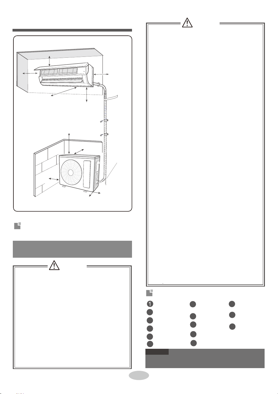
■
■
■
When refrigerant needs to be recovered
during relocating or repairing the unit, be
When installing or relocating the unit, be s-
ure to keep the refrigerant
circuit free from
air or substances other than the specified
refrigerant.
Any presence of air or other foreign substance
in the refrigerant circuit will cause
system pre-
ssure rise or compressor rupture, resulting
in injury.
When in
stalling or moving this unit, do not
charge the refrigerant which is not comply
with that on the nameplate or unqualified
refrigerant.
Otherwise, it may cause abnormal operation,
wrong action
, mechanical malfunction or even
serious safety accident.
■
■
■
■
■
When installing the unit, make sure that co-
nnection pipe is securely connected before
the compressor starts running.
If compressor starts running when stop valve
is open and connection pipe is not yet conne-
cted, air will be sucked in and cause pressure
rise or compressor rupture, resulting in injury.
Electric wires with insufficient capacity, wrong
wire connections and insecure wire terminals
may cause electric shock or fire.
1 minute.
sure that the unit is running in cooling mode.
Then, fully close the valve at high pressure
side (liquid valve). About 30-40 seconds later,
fully close the valve at low pressure side
(gas valve), immediately stop the unit and
disconnect power. Please note that the time
for refrigerant recovery should not exceed
Use the specified types of wires for electrical
connections between the indoor and outdoor
units. Firmly clamp the wires so that their te-
rminals receive no external stresses.
If refrigerant recovery takes too much time,
air may be sucked in and cause pressure
rise or compressor rupture, resulting in injury.
During refrigerant recovery, make sure that
liquid valve and gas valve are fully closed
and power is disconnected before detachi-
ng the connection pipe.
If compressor starts running when stop valve
is open and connection pipe is not yet conn-
ected, air will be sucked in and cause pressure
rise or compressor rupture, resulting in injury.
Prohibit installing the unit at the place where
there may be leaked corrosi
ve gas or flamm-
able gas.
If there is leaked gas around the unit, it may
cause explosion and other accidents.
Do not use extension cords for electrical co-
nnections. If the electric wire is not long eno-
ugh, please contact a local service center au-
thorized and ask for a proper electric wire.
Poor connections may lead to electric shock or fire.
2
2
Avis d'installation
7
12
8
3
9
4
13
Pour garantir la sécurité, veuillez respecter les
consignes suivantes.
5
6
14
10
11
AVERTISSEMENT
Tournevis
Perceuse à percussion
Clé plate
Coupe-conduits
Pompe à vide
Détecteur de fuites
Pressiomètre
Ruban à mesurer
Tête de forage
REMARQUE
Outils pour l'installation
13
Tuyau de drainage
Consignes de sécurité pour l'installation
et le déplacement de l'unité
Espace au mur d'au
moins 15 cm
Espace au mur d'au
moins 15 cm
Espace à l'obstruction d'au
moins 300 cm
Espace au sol d'au
moins 250 cm
AVERTISSEMENT
Espace à l'obstruction d'au
moins 50 cm
Espace au plafond d'au moins 15 cm
Espace à l'obstruction d'au
moins 30 cm
Espace à l'obstruction d'au
moins 50 cm
Espace à l'obstruction d'au
moins 200 cm
Espace au mur d'au
moins 30cm
Indicateur de niveau
Expandeur de tuyau
Clé dynamométrique
Clé hexagonale intérieure
Multimètre
● Veuillez contacter l'agent local pour l'installation.
● N'utilisez pas de puissance de refroidissement non qualifiée.
Si la récupération du réfrigérant prend trop de temps,
l'air peut être aspiré, ce qui peut provoquer une
augmentation de la pression ou une rupture du
compresseur, entraînant des blessures.
■ Lors de l'installation ou du déplacement de l'unité, veillez à maintenir le
circuit de réfrigérant exempt d'air ou de substances autres que le
réfrigérant spécifié
Toute présence d'air ou de toute autre substance étrangère dans le circuit
de réfrigérant entraînera une augmentation de la pression du système ou
une rupture du compresseur, entraînant des blessures.
■ Lors de l'installation ou du déplacement de l'unité, ne chargez pas le
réfrigérant qui n'est pas conforme à celui indiqué sur la plaque
signalétique ou le réfrigérant non qualifié.
Sinon, cela peut entraîner un fonctionnement anormal, une mauvaise
action, un dysfonctionnement mécanique ou même un grave accident de
sécurité.
■ Lorsque le réfrigérant doit être récupéré pendant le déménagement ou la
réparation de l'unité, assurez-vous que l'unité fonctionne en mode de
refroidissement. Ensuite, fermez complètement la vanne de côté haute
pression (vanne de liquide). Environ 30 à 40 secondes plus tard, fermez
complètement la vanne de côté basse pression (vanne de gaz), arrêtez
immédiatement l'unité et débranchez l'alimentation. Veuillez noter que la
durée de récupération du réfrigérant ne doit pas dépasser 1 minute.
■ Il est interdit d'installer l'unité à un endroit où il peut y
avoir une fuite de gaz corrosif ou de gaz inflammable.
S'il y a une fuite de gaz autour de l'unité, cela peut
provoquer une explosion et d'autres accidents.
■ N'utilisez pas de rallonges pour les connexions
électriques. Si le fil électrique n'est pas assez long,
veuillez contacter un centre de service local agréé et lui
demander un fil électrique approprié.
De mauvaises connexions peuvent entraîner un choc
électrique ou un incendie.
■ Utilisez les types de fils spécifiés pour les connexions
électriques entre les unités intérieure et extérieure. Serrez
fermement les fils afin que leurs bornes ne reçoivent
aucune contrainte extérieure.
Des fils électriques de capacité insuffisante, de
mauvaises connexions des fils et des bornes de fil mal
fixées peuvent provoquer une électrocution ou un
incendie.
■ Pendant la récupération du réfrigérant, assurez-vous que
la vanne de liquide et la vanne de gaz sont complètement
fermées et que la puissance est déconnectée avant de
détacher le tuyau de raccordement.
Si le compresseur commence à fonctionner lorsque la
vanne d'arrêt est ouverte et que le tuyau de raccordement
n'est pas encore connecté, l'air sera aspiré, ce qui
provoquera une augmentation de la pression ou une
rupture du compresseur, entraînant des blessures.
■ Lors de l'installation de l'unité, assurez-vous que le tuyau
de raccordement est solidement connecté avant que le
compresseur ne commence à fonctionner.
Si le compresseur commence à fonctionner lorsque la
vanne d'arrêt est ouverte et que le tuyau de raccordement
n'est pas encore connecté, l'air sera aspiré, ce qui
provoquera une augmentation de la pression ou une
rupture du compresseur, entraînant des blessures.

8.
Select a location where the condensation water
2.
4.
5.
3.
3.
4.
Installing the unit in the following places may cau-
se malfunction. If it is unavoidable, please consu-
lt the local dealer:
5.
6.
7.
laundry.
1.
2.
5.
can be dispersed easily and won't affect other
people.
2.
Select a location which is out of reach for chil-
dren and far away from animals or plants. If it
is unavoidable, please add the fence for safety
purpose.
1.
5.
6.
2.
It’s not allowed to be installed on
the unstable
or motive base structure
(such as truck) or in
the corrosive environment (such as chemical
factory).
3.
3.
Select a location which is convenient to conne-
ct the outdoor unit and near the power socket.
Do not put through the power before finishing
4.
Make sure that the installation follows the req-
uirement of installation dimension diagram.
There should be no obstruction near air inlet
and air outlet.
4.Select a location which is out of reach for children.
Must follow the electric safety regulations w-
hen installing the unit.
2.
air emitted by the outdoor unit will not affect
neighborhood.
installation.
7.
If the supply cord is damaged, it must
be repla-
The location should be well ventilated and dry,
in which the outdoor unit won't be exposed dir-
ectly to sunlight or strong wind.
The location should be able to withstand the
weight of outdoor unit.
According to the local safety regulations, use
1.Select a location where the noise and outflow
qualified power supply circuit and air s
witch.
7.
8.Please try your best to keep way from fluores-
cent lamp.
The yellow-green wire in air conditioner is
grounding wire, which can 't be used for other
purposes.
An all-pole disconnection switch having a co-
ntact separation of at least 3mm in all poles
should be connected in fixed wiring.
The grounding resistance should comply with
weight of indoor unit and won't increase noise
and vibration.
The appliance must be installed 2.5m above
floor.
Don't install the indoor unit right above the ele-
ctric appliance.
1.
The place with sulfureted gas.
Other places with special circumstances.
The appliance shall not be installed in the
The place with strong hea t sources,
vapors,
flammable or explosive gas, or volatile objects
spread in the air.
The place with high-frequen cy devices (such
as welding machine, medical equipment).
The place near coast area.
The place with oil or fumes in the air.
with national wiring regulations.
8.
The temperature of refrigerant circuit will be hi-
4.Properly connect the live wire, neutral wire and
from the copper tube.
9.
The appliance shall be installed in accordance
6.
1.
T
he air conditioner is the first class
electric
3.
appliance. It must be properly grounded with
specialized grounding
device by a professional.
Please make
sure it is always grounded effecti-
vely, otherwise it may cause electric shock.
ced by the manufacturer, its
service agent or
similarly qualified
persons in order to avoid a
hazard .
national electric safety regulations.
The appliance must be positioned so tha t the
p
l
u
g is accessible.
The location should be able to withstand t he
Make sure the power supply matches with the
requirement of air conditioner.
Unstable power
supply or incorrect wiring or malfunction. Pl-
ease install proper power supply cables before
using the air
conditioner.
gh, please keep the interconnection cable away
grounding wire of power socket.
5.
Be sure to cut off the power supply
before pr-
oceeding any work related to
electricity and safety.
Including an air switch with suitable capacity,
please note the following table . Air switch sh-
ould be included magne t buckle and heating
buckle function, it can protec t the circuit-short
and overload. (Caution: please do no t use the
fuse only for
protecting the circuit)
14
Sélection de l'emplacement d'installation
Exigences pour la connexion électrique
Capacité du commutateur d'air
Unité intérieure
Exigences de base
Consignes de sécurité
Exigences de mise à la terre
Unité extérieure
Climatiseur
Capacité du
commutateur d'air
09K、12K
10A
18K
16A
24K
25A
1. Il faut suivre les réglementations de sécurité électrique lors
de l'installation de l'unité.
2. Conformément aux réglementations de sécurité locales,
utilisez le circuit d'alimentation et le commutateur d'air
qualifiés.
L'installation de l'unité dans les endroits suivants peut
entraîner un dysfonctionnement. Si cela est inévitable,
veuillez consulter le revendeur local :
1. Endroit avec de fortes sources de chaleur, des vapeurs, des
gaz inflammables ou explosifs ou des objets volatils
répandus dans l'air.
2. Endroit avec des appareils à haute fréquence (tels que des
machines à souder et des équipements médicaux).
3. Endroit près de la côte.
4. Endroit avec de l'huile ou des fumées dans l'air.
5. Endroit avec du gaz sulfuré.
6. Autres endroits avec des circonstances particulières.
7. L'appareil ne doit pas être installé dans la buanderie.
8. Il ne peut pas être installé sur la structure de base instable
ou mobile (comme un camion) ou dans un environnement
corrosif (comme une usine chimique).
Y compris un commutateur d'air avec une capacité
appropriée, veuillez noter le tableau suivant. Le commutateur
d'air doit avoir une fonction de boucle magnétique et de
boucle chauffante, ce qui peut réaliser la protection entre le
court-circuit et la surcharge. (Attention : veuillez ne pas
utiliser le fusible uniquement pour protéger le circuit)
3. Assurez-vous que l'alimentation électrique correspond aux
exigences du climatiseur -Alimentation électrique instable
ou câblage incorrect ou dysfonctionnement. Veuillez
installer les câbles d'alimentation appropriés avant d'utiliser
le climatiseur.
4. Connectez correctement le fil sous tension, le fil neutre et
le fil de mise à la terre de la prise de courant.
5. Assurez-vous de couper l'alimentation électrique avant de
procéder à tout travail lié à l'électricité et à la sécurité.
6. Ne mettez pas l'appareil sous tension avant de terminer
l'installation.
7 Si le cordon d'alimentation est endommagé, il doit être
remplacé par le fabricant, son agent de service ou des
personnes qualifiées similaires afin d'éviter tout danger.
8. La température du circuit de réfrigérant sera élevée,
veuillez éloigner le câble d'interconnexion du tube de
cuivre.
9. L'appareil doit être installé conformément aux réglementa-
tions nationales en matière de câblage.
1. Sélectionnez un emplacement où le bruit et l'air émis par
l'unité extérieure n'affecteront pas le voisinage.
2. L'emplacement doit être bien ventilé et sec, dans lequel
l'unité extérieure ne sera pas exposée directement à la
lumière du soleil ou au vent fort.
3. L'emplacement doit pouvoir supporter le poids de l'unité
extérieure.
4. Assurez-vous que l'installation respecte les exigences du
diagramme des dimensions d'installation.
5. Choisissez un emplacement hors de portée des enfants et
loin des animaux ou des plantes. Si cela est inévitable,
veuillez ajouter la clôture pour des raisons de sécurité.
1. Il ne doit y avoir aucune obstruction près de l'entrée d'air et
de la sortie d'air.
2. Choisissez un emplacement où l'eau de condensation peut
être facilement dispersée et n'affectera pas les autres
personnes.
3. Sélectionnez un emplacement pour connecter l'unité
extérieure et à proximité de la prise de courant.
4. Choisissez un emplacement hors de portée des enfants.
5. L'emplacement doit pouvoir supporter le poids de l'unité
intérieure et n'augmentera pas le bruit et la vibration.
6. L'appareil doit être installé à 2,5 m au-dessus du sol.
7. N'installez pas l'unité intérieure juste au-dessus de l'appareil
électrique.
8. Veuillez faire de votre mieux pour vous éloigner de la
lampe fluorescente.
1 Le climatiseur est l'appareil électrique de première classe.
Il doit être correctement mis à la terre par un professionnel
avec un dispositif de mise à la terre spécialisé.
Assurez-vous qu'il est toujours correctement mis à la terre,
sinon cela peut provoquer un choc électrique.
2. Le fil jaune-vert du climatiseur est un fil de mise à la terre,
qui ne peut pas être utilisé à d'autres fins.
3. La résistance de mise à la terre doit être conforme aux
réglementations nationales en matière de sécurité
électrique.
4. L'appareil doit être positionné de telle sorte que la prise
soit accessible.
5. Un sectionneur omnipolaire doté d'une séparation de
contact d'au moins 3 mm sur tous les pôles doit être
connecté dans le câblage fixe.

Accessoires
15
Qté (pcs)
Vis de fixation de la plaque de montage
Accessoires
Tuyau de vidange (optionnel)
Intérieur
Isolateur
Plaque de montage
Forme
Vis de fixation pour le support de
télécommande
Support de télécommande
Tuyau (optionnel)
Extérieur
Qté (pcs)Accessoires
Câble d'assemblage (optionnel)
Batterie
Manuel d'utilisation
Couvercle d'installation (optionnel)
Télécommande
ÉCROU
Forme
Ruban en vinyle
(optionnel)
Ancre
Joint de vidange
(pour les modèles de refroidissement et de
chauffage)
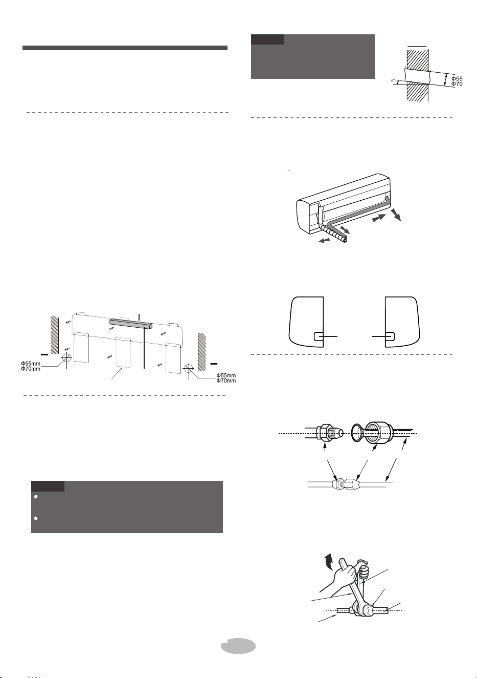
2.
3.
Fix the wall-mounting frame on the wall with
tapping screws and then check if the frame
is firmly installed by pulling the frame. If the
plastic expansion particle is loose, please
drill another fixing hole nearby.
1.
Hang the wall-mounting frame on the wall; adjust
it in horizontal position with the level meter and
then point out the screw fixing holes on the wall.
Drill the screw fixing holes on the wall with im-
pact drill(the specification of drill head should
be the same as the plastic expansion particle)
and then fill the plastic expansion particles in
the holes.
2.
3.
1.
wall-mounted frame, shown as below.
Choose the position of piping hole according
When installation is finished, pull the mounting
plate with hand to confirm whether it is fixed
tightly. The force distribution for all screws
should be uniform.
Open a piping hole with the diameter of 55
or 0 on the selected outlet pipe position.
In order to drain smoothly, slan t the piping
hole o
n the wall slightly downward to the
outdoor side with the gradient of 5-10°.
to the direction of outlet pipe. The position of
piping hole should be a little lower than the
Pay attention to dust prevention
and take rele vant safety mea-
sures when opening the hole.
2.
2.
3.
1. Aim the pipe joint at the corresponding
rear right, left or rear left.
bellmouth.
Pretighten the union nut with hand.
1. The pipe can be led out in the direction of right,
Adjust the torque for
ce by referring to the
wrench on the union nut. Tighten the union
nut with torque wrench.
When select leading out the pipe from left or
right, please cut off the corresponding hole on
the bottom case.
following sheet. Place the open-end wren-
ch on the pipe join t and place the torque
extérieurIntérieur
5-10
arrière gauche
percez le
trou
Écrou de raccordementjoint de tuyaux
tuyau
Remarque
Installez le support de montage mural
Étape 2:
Tuyau de sortie
Choisissez l'emplacement d'installation
Étape 1:
Recommandez l'emplacement d'installation au client, puis
confirmez-le avec le client.
droite
Étape 4:
Étape 3:
Ouvrez le trou de tuyauterie
Étape 5:
Connectez le tuyau de l'unité intérieure
Installation de l'unité intérieure
Remarque
gauche droite
gauche
Veuillez vous référer aux circonstances réelles pour le
nombre et la position des vis.
arrière droite
15
Le panneau mural est à titre indicatif seulement,
veuillez vous référer à l'installation réelle.
Écrou de raccordement
Clé dynamométrique
tuyau
Tuyau intérieur
Clé plate
Mur
Mur
(Trou de tuyauterie arrière)
(Pour certains modèles)
(Trou de tuyauterie arrière)
Espace au
mur au-dessus
de 150mm
Gauche
Espace au mur
au-dessus de
150mm
Droite
Marque au milieu
Indicateur de niveau
16
3. Ajustez la force de couple en vous reportant à la feuille
suivante. Placez la clé à fourche sur le joint de tuyau et placez
la clé dynamométrique sur l'écrou raccord. Serrez l'écrou
raccord avec une clé dynamométrique
2. Lorsque l'installation est terminée, tirez la plaque de
montage avec la main pour confirmer si elle est bien fixée.
La distribution de force pour toutes les vis doit être
uniforme.
3. Ouvrez un trou de tuyauterie d'un diamètre de Ø55 ou Ø70 à
la position sélectionnée du tuyau de sortie. Pour que la
vidange se fasse en douceur, inclinez le trou de tuyauterie
sur le mur légèrement vers le bas du côté extérieur avec une
pente de 5 à 10°.
• Faites attention à la prévention de la
poussière et prenez les mesures de
sécurité appropriées lors de l'ouverture
du trou.
2. Lorsque vous le tuyau sortant de gauche ou de droite,
veuillez percer le trou correspondantsur le boîtier inférieur.
1. Le tuyau peut être dirigé vers la droite, l'arrière droite, la
gauche ou l'arrière gauche.
1. Dirigez le joint de tuyau vers l'évasement correspondant.
2. Pré-serrez l'écrou raccord à la main.
1. Choisissez la position du trou de tuyauterie en fonction de la
direction du tuyau de sortie. La position du trou de tuyauterie
doit être un peu plus basse que le support de montage mural,
comme indiqué ci-dessous.
1. Accrochez le support de montage mural au mur; ajustez-le en
position horizontale avec l'indicateur de niveau puis pointez
les trous de fixation des vis sur le mur.
2. Percez les trous de fixation des vis sur le mur avec une
perceuse à percussion (la spécification de la tête de forage doit
être identique à celle du bouchon à expansion en plastique),
puis remplissez le bouchon à expansion en plastique dans les
trous.
3. Fixez le support de montage mural sur le mur à l'aide des vis
autotaraudeuses, puis vérifiez si le cadre est solidement
installé en tirant sur le cadre. Si le bouchon à expansion en
plastique est lâche, veuillez percer un autre trou de fixation à
proximité

4.
1.
2
.
1.
indoor unit.
Wrap the indoor pipe and joint of connection
pipe with insulating pipe, and then wrap it
with tape.
Open the panel, remove the screw on the wiring
cover and then take down the cover.
Connect the drain hose to the outlet pipe of
Make the power connection wire go through the
cable-cross hole at the back of indoor unit and
then pull it out from the front side.
●
Les bouchons à expansion en plastique ne sont pas fournis.
●
Tous les fils de l'unité intérieure et de l'unité extérieure
doivent être connectés par un professionnel.
●
Si la longueur du fil de raccordement électrique est
insuffisante, veuillez contacter le fournisseur pour en
obtenir un nouveau. Ne rallongez pas le fil vous-même.
Ajoutez un tuyau isolant dans le tuyau de vidange intérieur
afin d'éviter la condensation.
●
Pour le climatiseur avec prise, la prise doit être accessible
une fois l'installation terminée.
●
Panneau
tuyau de vidange
2.
Tuyau de sortie
ruban adhésif
Remarque
●
REMARQUE
Étape 7:
Connectez le fil de l'unité intérieure
Pour le climatiseur sans prise, un commutateur d'air doit
être installé dans la ligne. Le commutateur d'air doit se
séparer de tous les pôles et la distance de séparation des
contacts doit être supérieure à 3 mm.
Vis
couvercle de câblage
trou de passage
de câble
fil de raccordement
électrique
Étape 6:
Installez le tuyau de vidange
Enroulez le joint avec du ruban adhésif
.
tuyau isolant
tuyau isolant
tuyau de vidange
Tuyau de
sortie
tuyau de vidange
Diamètre de l'écrou
hexagonal
15~20
30~40
45~55
60~65
70~75
17
Tightening torque (N.m)
4. Enveloppez le tuyau intérieur et le joint du tuyau de
raccordement avec un tuyau isolant, puis enveloppez-le avec du
ruban adhésif.
1. Ouvrez le panneau, retirez la vis du couvercle de câblage, puis
démontez le couvercle.
2. Faites passer le fil de raccordement électrique à travers le trou
de passage de câble à l'arrière de l'unité intérieure, puis
retirez-le par l'avant.
1. Connectez le tuyau de vidange au tuyau de sortie de l'unité
intérieure.

3.
4.
5.
Remove the wire clip; connect the power conn-
ection wire to the wiring terminal according to
the color; tighten the screw and then fix the po-
wer connection wire with wire clip.
Put wiring cover back and then tighten the screw.
Close the panel.
1.
5.
crochet supérieur
Unité
intérieure
bande
REMARQUE
crochet inférieur du
support de montage mural
Le cordon d'alimentation et le fil de contrôle ne
peuvent pas être croisés ou enroulés.
Le tuyau de vidange doit être attaché au bas.
2.
intérieur
3.
tuyau mural
4.
4.
REMARQUE
extérieur
Étape 9:
Accrochez l'unité intérieure
2.
gomme d'étanchéité
tuyau de gaz
3.
Tuyau de liquide
Étape 8:
Reliez les tuyaux
tuyau de vidange
1.
cordon d'alimentation
intérieur et extérieur
REMARQUE
La carte de câblage est à titre indicatif uniquement,
veuillez vous référer à la carte de câblage réelle.
Ne pliez pas trop le tuyau de vidange afin d'éviter tout
blocage.
tuyau de raccordement
tuyau de vidange
bande
cordon d'alimentation intérieur
Mettez les tuyaux reliés dans le tuyau mural, puis
faites-les passer à travers le trou du mur.
Reliez le tuyau de raccordement, le cordon d’alimentation et le
tuyau de vidange avec la bande.
Reliez-les uniformément.
Le tuyau de liquide et le tuyau de gaz doivent
être reliés séparément à l'extrémité.
Accrochez l'unité intérieure sur le support de
montage mural.
Remplissez l'espace entre les tuyaux et le trou
du mur avec de la gomme d'étanchéité.
Fixez le tuyau mural.
Vérifiez si l'unité intérieure est installée solidement
et fermement au mur.
Connexion de l'unité extérieure
N(1) 2 3
jaune-vert
brunnoirbleu
Réservez une certaine longueur de tuyau de vidange et de
cordon d'alimentation pour l'installation lors de leur
raccordement. Lors du raccordement à un certain degré,
séparez l'alimentation intérieure, puis séparez le tuyau de
vidange.
18
4. Remettez le couvercle de câblage en place, puis serrez la vis.
5. Fermez le panneau.
3. Retirez l'agrafe de fil, connectez le fil de raccordement
électrique à la borne de câblage selon les couleurs; serrez la
vis, puis fixez le fil de raccordement électrique avec une
agrafe de fil.
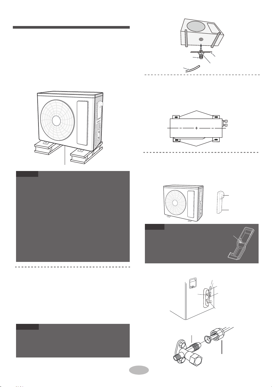
2.
1.
2.
1. Connect the outdoor drain joint into the hole
Select installation location according to
the house structure.
Fix the support of outdoor unit on the sele-
cted location with expansion screws.
on the chassis, as shown in the picture below.
Connect the drain hose into the drain vent.
As for the shape of drainage joint, please refer
to the current product. Do not install the drainage
joint in the severe cold area. Otherwise,it will be
frosted and then cause malfunction.
When there're multiple cables
passing through it, the cro
ss-hole
of handle should be knocked off
and eliminate the sharp burrs for
avoid damaging the cables.
Only applicable for some models.
Take sufficient protective measures when installin g
the outdoor unit.
Make sure the support can withstand at least fou r
times of the unit weight.
The outdoor unit should be installed at least
3cm above the floor in order to install drain joint.
(for the model with heating tube, the installation
height should be no less than 20cm.)
For the unit with cooling capacity of 2300W
~
5000W,
6 expansion screws are needed ; for
the unit with cooling capacity of 6000W~8000W,
8 expansion screws are needed; for the unit
with cooling capacity
of 10000W~16000W, 10
expansion screws are needed.
2. Fixez les trous de pied de l'unité extérieure avec des boulons.
Trous de pied
Trous de pied
1. Retirez la vis de la poignée droite de l'unité extérieure, puis
retirez la poignée.
(à choisir en fonction de la situation réelle de
l'installation)
Étape 1:
Fixez le support de l'unité extérieure
Vanne de gaz
Tuyau de liquide
tuyau de gaz
vanne de
liquide
Étape 4:
Connectez les tuyaux intérieurs et extérieurs
Écrou de raccordement
joint de tuyaux
Étape 3:
Fixez l'unité extérieure
REMARQUE
Installation de l'unité extérieure
Étape 2:
Installez le joint de vidange
(Uniquement pour certains modèles)
REMARQUE
Remarque
Trou transversal
2. Retirez le bouchon à vis de la vanne et orientez le
raccord de tuyau vers l'évasement du tuyau.
3.
Pré-serrez l'écrou-raccord à la main.
Poignée
Vis
évent de vidange
tuyau de vidange
châssis
Joint de vidange extérieur
au moins 3 cm au-dessus du sol
19
1. Placez l'unité extérieure sur le support.
• En ce qui concerne la forme du joint de vidange, veuillez
se reporter au produit réel. N'installez pas le joint de
vidange dans la zone très froide. Sinon, il sera givré et
cela provoquera alors un dysfonctionnement.
1. Connectez le joint de vidange extérieur dans le trou sur le
châssis, comme indiqué dans l'image ci-dessous.
2. Connectez le tuyau de vidange dans l'évent de vidange.
• Prenez des mesures de protection suffisantes lors de
l'installation de l'unité extérieure.
• Assurez-vous que le support peut supporter au moins
quatre fois le poids de l'unité.
• L'unité extérieure doit être installée à au moins 3 cm du
sol afin d'installer le joint de vidange (pour le modèle
avec tuyau de chauffage, la hauteur d'installation ne doit
pas être inférieure à 20 cm).
• 6 vis d'expansion sont nécessaires pour l'unité avec une
capacité de refroidissement de 2300W~5000W ; 8 vis
d'expansion nécessaires pour l'unité avec une capacité de
refroidissement de 6000W~8000W ; et 10 vis
d'expansion nécessaires pour l'unité avec une capacité de
refroidissement de 10000W-16000W.
• Lorsque plusieurs câbles passent par le
support, il faut enlever le trou transversal de
la poignée et éliminer les bavures
tranchantes pour éviter d'endommager les
câbles.
• Applicable uniquement à certains modèles.
1. Sélectionnez l'emplacement d'installation en fonction de la
structure de la maison.
2. Fixez le support de l'unité extérieure à l'emplacement choisi à
l'aide de vis d'expansion.
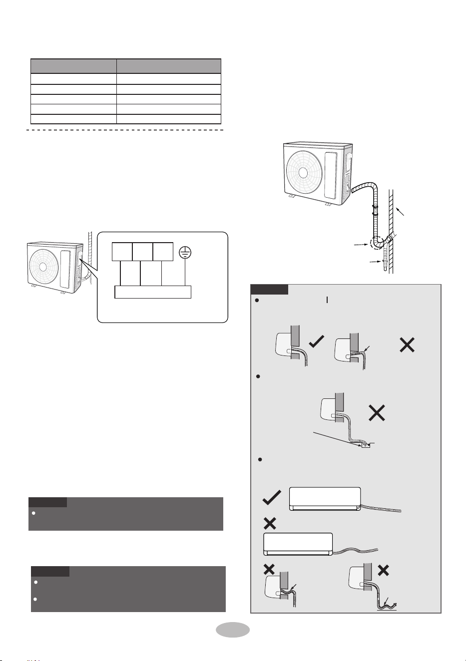
4.
2.
1.
Tighten the union nu t with torque wrench
by referring to the sheet below.
The pipes should be placed along the wall, bent
If the outdoor unit is higher than the wall hole,
reasonably and hidden possibly. Min. semidiam-
eter of bending the pipe is 10cm.
you must set a U-shaped curve in the pipe
before pipe goes into the room, in order to
prevent rain from getting into the room.
1. Retirez l'agrafe de fil ; connectez le fil de connexion électrique
et le fil de contrôle du signal (uniquement pour l'unité de
refroidissement et de chauffage) à la borne de câblage selon la
couleur ; fixez-les avec des vis.
Diamètre de l'écrou hexagonal Couple de serrage (N m)
.
mur
Le tuyau de vidange ne peut pas être fluctué
La sortie d'eau ne peut pas être placée dans l'eau pour
que la vidange se fasse en douceur.
2.
1/4''
3/8''
1/2''
5/8''
3/4''
15~20
30~40
45~55
60~65
70~75
Connectez le fil électrique extérieur
Étape 5:
Le tuyau de vidange ne peut
pas se relever vers le haut.
La sortie d'eau ne
peut pas être
placée dans l'eau
Inclinez le tuyau de vidange légèrement vers le bas.
Le tuyau de vidange ne peut pas être courbé, soulevé
et fluctué, etc.
Le tuyau de
vidange ne peut
pas être fluctué
La sortie d'eau ne
doit pas être fluctuée
Fixez le fil de connexion électrique et le fil de contrôle du
signal à l'aide d'une agrafe de fil (uniquement pour les unités
de refroidissement et de chauffage).
Étape 6:
Nettoyez les tuyaux
Courbe en U
tuyau de vidange
REMARQUE
REMARQUE
REMARQUE
La carte de câblage est à titre indicatif uniquement,
veuillez vous référer à la carte de câblage réelle.
Après avoir serré la vis, tirez légèrement sur le cordon
d'alimentation pour vérifier s'il est bien fixé.
Ne coupez jamais le fil de connexion électrique pour
prolonger ou raccourcir la distance.
La hauteur à travers le mur du tuyau de vidange ne doit
pas être supérieure à celle de l'orifice du tuyau de sortie
de l'unité intérieure.
Connexion de l'unité intérieure
N(1) 2 3
bleu
noir
brun
jaune-vert
20
4. Serrez l'écrou-raccord avec une clé dynamométrique en vous
référant à la fiche ci-dessous.
1. Les tuyaux doivent être placés le long du mur, pliés raisonnable-
ment et cachés éventuellement. Le demi-diamètre minimum de
cintrage du tuyau est de 10 cm.
2. Si l'unité extérieure est plus haute que le trou du mur, vous
devez placer une courbe en U dans le tuyau avant que le tuyau
n'entre dans la pièce, afin d'empêcher la pluie de pénétrer dans
la pièce.

serp ,rewop eht hguorht tuP
s " ON/OFF " button on
the remote controller to start operation.
Press MODE button to select AUTO, COOL, DRY ,
FAN and HEAT to check whether the operation s i
normal or not.
If the ambient temperature is lower than 16℃ e ht ,
air conditioner can’t start cooling.
●
●
●
Test de fonctionnement
Test et fonctionnement
1.
●
●
Préparation du test de fonctionnement
Le client approuve le climatiseur.
Spécifiez au client les notes importantes pour le climatiseur.
6.
Détection des fuites
Utilisez la pompe à vide
Serrez les bouchons à vis des vannes et de l'évent de charge du
réfrigérant.
1.
2.
5.
4.
1.
Réinstallez la poignée.7.
Retirez le piézomètre, ouvrez complètement le noyau de la
vanne de liquide et de la vanne de gaz avec une clé
hexagonale intérieure.
piézomètre
Capuchon de vanne
vanne de liquide
Lo Hi
Vanne de gaz
évent de charge du
réfrigérant
écrou de l'évent de
charge du
réfrigérant
fermer
ouvrir
Pompe à vide
Clé hexagonale
intérieure
Fermez la pompe à vide et maintenez ce statut pendant 1 à 2
minutes pour vérifier si la pression du piézomètre reste à
-0,1MPa. Si la pression diminue, il peut y avoir une fuite.
21
2.
3.
Ouvrez complètement le piézomètre et faites-le
fonctionner pendant 10-15 minutes pour vérifier si la
pression du piézomètre reste à -0,1MPa.
Retirez les capuchons des vannes de liquide et de gaz et
l'écrou de l'évent de charge du réfrigérant.
Avec un détecteur de fuites :
Avec de l'eau savonneuse :
Si le détecteur de fuites n'est pas disponible, veuillez
utiliser de l'eau savonneuse pour détecter les fuites.
Appliquez de l'eau savonneuse à l'endroit suspecté et
gardez l'eau savonneuse pendant plus de 3 minutes. Si
des bulles d'air sortent de cette position, il y a une fuite.
Vérifiez après l'installation
●
Vérifiez les exigences suivantes après avoir terminé
l'installation.
Défaillance éventuelle
L'unité peut tomber, trembler ou
émettre des bruits.
L'eau est-elle bien drainée ?
Cela peut provoquer de la
condensation et des gouttes d'eau.
Éléments à vérifier
L'unité a-t-elle été
installée fermement ?
Avez-vous effectué le test de
fuite du réfrigérant ?
Cela pourrait entraîner une
défaillance ou endommager les
pièces.
Le câblage électrique et la
tuyauterie sont-ils installés
correctement ?
Cela pourrait entraîner une
défaillance ou endommager les
pièces.
L'unité est-elle bien mise à
la terre ?
Le cordon d'alimentation est-il
conforme aux spécifications ?
Cela pourrait entraîner une
défaillance ou endommager les
pièces.
Y a-t-il une obstruction à
l'entrée et à la sortie d'air ?
Cela pourrait entraîner une
défaillance ou endommager les
pièces.
La vanne de gaz et la vanne de
liquide du tuyau de raccordement
sont complètement ouvertes ?
Les poussières et les saletés
causées pendant l'installation sont
éliminées ?
L'isolation thermique de la
tuyauterie est-elle suffisante ?
L'entrée et la sortie du trou de la
tuyauterie sont-elles couvertes ?
La tension de l'alimentation
électrique correspond-elle à la
tension indiquée sur la plaque
signalétique ?
Cela peut entraîner une capacité de
refroidissement (chauffage)
insuffisante ou un gaspillage
d’énergie électrique.
Méthode de test de fonctionnement2.
Raccordez le tuyau de charge du piézomètre à l'évent de
charge du réfrigérant de la vanne de gaz, puis raccordez
l'autre tuyau de charge à la pompe à vide.
Vérifiez s'il y a une fuite avec le détecteur de fuites.
Cela peut entraîner une capacité de
refroidissement (chauffage) insuffisante.
Cela peut provoquer de la
condensation et des gouttes d'eau.
Cela peut provoquer des fuites
électriques.
Cela peut entraîner une capacité
de refroidissement (chauffage)
insuffisante.
Cela peut entraîner une capacité
de refroidissement (chauffage)
insuffisante.
• Mettez sous tension, appuyez sur le bouton "ON/OFF" de la
télécommande pour démarrer le fonctionnement.
• Appuyez sur le bouton MODE pour sélectionner AUTO,
REFROIDISSEMENT, SÉCHAGE, VENTILATEUR et
CHAUFFAGE afin de vérifier si le fonctionnement est
normal ou non.
• Si la température ambiante est inférieure à 16ºC, le
climatiseur ne peut pas commencer à refroidir.

1.
2.
3.
Standard length of connection pipe: 5m, 7.5m,
4.
The additional refrigerant oil and refrigerant charg-
ing required after prolonging connection pipe.
8m.
Min. length of connection pipe is 3m.
Max. length of connection pipe is shown as below.
After the length of connection pipe is prolonged
for 10m at the basis of standard length, you should
add 5ml of refrigerant oil for each additional 5m
of connection pipe.
The calculation method of additional refrigerant
charging amount(on the basis of liquid pipe):
Additional refrigerant charging amount =
prolonged length of liquid pipe × additional
refrigerant charging amount per meter
Basing on the length of standard pipe, add re-
frigerant according to the requirement as shown
in the table. The additional refrigerant charging
amount per meter is different according to the
diameter of liquid pipe. See the following sheet.
Improper pipe expanding is the main cause of refriger-
ant leakage. Please expand the pipe according to the
following steps:
●
●
●
22
15
15
15
20
25
Longueur maximale
du tuyau de
raccordement (m)
25
30
30
30
30
Longueur maximale du tuyau de raccordement
Méthode de rallongement du tuyau
Capacité de refroidissement
5000Btu/h (1465W)
7000Btu/h (2051W)
9000Btu/h (2637W)
12000Btu/h (3516W)
18000Btu/h (5274W)
24000Btu/h (7032W)
28000Btu/h (8204W)
36000Btu/h (10548W)
42000Btu/h (12306W)
48000Btu/h (14064W)
Coupe-conduits
tuyau
●
A: Coupez le tuyau
●
penché
burr
inégale
Configuration du tuyau de raccordement
Confirmez la longueur du tuyau en fonction de la distance entre
l'unité intérieure et l'unité extérieure.
Coupez le tuyau requis à l'aide d'un coupe-tuyau.
15
Montant de charge du réfrigérant supplémentaire pour le R22,
le R407C, le R410A et le R134a
20
15
50
30
REMARQUE
120
60
120
250 250
350 350
tuyau de gaz
3/8'' ou 1/2''
5/8'' ou 3/4''
3/4'' ou 7/8''
1'' ou 1 1/4''
_
_
Taille de la tuyauterie
Tuyau de liquide
1/4''
Papillon de l'unité extérieure
Refroidissement
seulement (g/m)
Refroidissement et
chauffage (g/m)
1/4'' ou 3/8''
1/2''
5/8''
3/4''
7/8''
• Méthode de calcul de charge du réfrigérant supplémentaire
(sur la base du tuyau de liquide) : Quantité de charge du
réfrigérant supplémentaire = Longueur prolongée du tuyau
de liquide x Quantité de charge du réfrigérant supplémen-
taire par mètre.
• En fonction de la longueur du tuyau standard, ajoutez du
réfrigérant selon les besoins, comme indiqué dans le
tableau. La quantité de charge du réfrigérant supplémen-
taire par mètre est différente selon le diamètre du tuyau de
liquide. Voir la fiche suivante.
4. L'huile réfrigérante et le charge du réfrigérant supplémen-
taires sont nécessaires après le prolongement du tuyau de
raccordement.
• Après avoir prolongé la longueur du tuyau de raccordement
de 10 m sur la base de la longueur standard, vous devez
ajouter 5 ml d'huile réfrigérante pour chaque 5 m
supplémentaire de tuyau de raccordement.
L'expansion inadéquate des tuyaux est la principale cause de
fuite du réfrigérant. Veuillez élargir le tuyau en suivant les
étapes suivantes :
1. Longueur standard du tuyau de raccordement : 5m, 7,5m,
8m.
2. La longueur minimale du tuyau de raccordement est de 3
m.
3. La longueur maximale du tuyau de raccordement est
indiquée ci-dessous.

Check the quality of expanding port. If there is
●
any blemish, expand the port again according to
the steps above.
The operating temperature range (outdoor tem -
●
perature) for cooling onl y
unit is 18
°C
~48
°C
;for
heat pump unit is -7
°C
~48
°C
.
The operating temperature range (outdoor tem -
●
perature) for cooling onl y
unit is 18
°C
~43
°C
;for
heat pump unit is -7
°C
~43
°C
.
Enlevez les bavures à l'aide d'une fraise et empêchez
les bavures de pénétrer dans le tuyau.
la longueur est égale
Plage de température de service
Tuyau de
raccordement
tuyau
2
D : Mettez un tuyau isolant approprié
Surface lisse
Expansion inappropriée
épaisseur
inégale
penché
surface
endommagée
fissure
Expandeur
tuyau
moule
dur
REMARQUE
●
●
B: Enlever les bavures
D : Mettez l'écrou de raccordement
●
●
E: Étendre le port
F: Inspection
fraise
Vers le bas
tuyau
A(mm)
Max
Min
Φ6 - 6.35(1/4")
1.3 0.7
1.6 1.0Φ9 - 9.52(3/8")
Φ12-12.7(1/2")
1.8 1.0
Φ15.8-16(5/8")
2.4 2.2
Diamètre extérieur
(mm)
32/23 48/26
27/- 24/18
Côté intérieur
DB/WB(°C)
Côté extérieur
DB/WB(°C)
Côté intérieur
DB/WB(°C)
Côté extérieur
DB/WB(°C)
Refroidisse-
ment maximal
Chauffage
maximal
Remarque
32/23 43/26
27/- 24/18
Refroidisse-
ment maximal
Chauffage
maximal
Remarque
Onduleur SA 09K, 12K, 18K, 24K:
Onduleur AF 09K, 12K, 18K, 24K:
Retirez l'écrou de raccordement sur le tuyau de
raccordement intérieur et la
vanne extérieure ; installez
l'écrou de raccordement
sur le tuyau.
Élargissez le port avec l'expandeur.
"A" est différent selon le diamètre, veuillez vous
référer à la fiche ci-dessous :
La plage de température de fonctionnement (température
extérieure) pour l'unité de refroidissement seul est de 18°C~43°C ;
et -7°C~43°C pour l'unité de pompe à chaleur.
La plage de température de fonctionnement (température
extérieure) pour l'unité de refroidissement seul est de 18°C~48°C
; et -7°C~48°C pour l'unité de pompe à chaleur.
Vérifiez la qualité du port d'expansion. S'il y a un défaut,
élargissez à nouveau le port en suivant les étapes ci-dessus.

PAYS APPELER OU VISITER EN LIGNE À
AFRIQUE DU SUD 0860 SAMSUNG (726 7864) www.samsung.com/za/support
NAMIBIA 08 197 267 864
www.samsung.com/africa_en/support
ZAMBIA
3434
MAURITIUS
800 5050
NIGERIA 0800 726 7864
GHANA 0800 100 077
KENYA 0800 545 545
UGANDA 0800 300 300
TANZANIA 0800 780 089
RÉUNION 0262 50 88 80
www.samsung.com/africa_fr/support
Cote D’Ivoire 8000 0077
SENEGAL 800 00 0077
CAMEROUN 67095 0077
MOZAMBIQUE 84 726 7864 www.samsung.com/africa_pt/support
SUDAN 1969 www.samsung.com/eg/support
QUESTIONS OU COMMENTAIRES ?
Cover_GREE_AFRICA.indd 2 2019-10-25 오후 3:14:38
66139903397
Ar Condicionado
• Agradecemos a sua compra deste ar condicionado Samsung.
• Antes de operar esta unidade, leia atentamente este manual e guarde-o para referência futura.
Capa_GREE_ÁFRICA.indd 1 2019-10-25 오후 3:14:38
AR**B*HGAWK***
Manual do utilizador/Manual de instalação

Conteúdo
Notas para o funcionamento
Precauções........................................................................................................................1
Nome das peças................................................................................................................6
Guia de operações do ecrã
Botões no controlo remoto...............................................................................................7
Introdução para ícones do ecrã de exibição .....................................................................7
Introdução para botões no controlo remoto .....................................................................8
Introdução de funções para botões de combinação........................................................10
Manutenção
Limpeza e manutenção ..................................................................................................11
Verifique os itens antes da manutenção.........................................................................12
Aviso de Instalação
Diagrama das dimensões de instalação..........................................................................13
Seleção do local para instalação ....................................................................................14
Requisitos para a ligação elétrica...................................................................................14
Precauções de segurança para a instalação e mudança de local da unidade..................13
Acessórios......................................................................................................................15
Instalação
Instalação de unidade interior ........................................................................................16
Instalação da unidade exterior .......................................................................................19
Teste e operação
Operação de teste ...........................................................................................................21
Anexo
Configuração da tubagem de ligação.............................................................................22
Método de expansão de tubos........................................................................................22
Ferramentas para instalação...........................................................................................13
Capacidade do interruptor de ar.....................................................................................14

Explicação dos Símbolos
1. Danos no produto causados por uso incorreto ou inadequado do produto;
2. Alterar, substituir, fazer a manutenção ou utilizar o produto com outro equipamento sem
respeitar o manual de instruções do fabricante;
3. Após a verificação, os defeitos do produto são causados diretamente pelo gás corrosivo;
4. Após a verificação, os defeitos causados pelo funcionamento incorreto durante o transporte
do produto;
5. Utilização, reparação, manutenção da unidade sem respeitar o manual de instruções ou
regulamentações relacionadas;
6. Após a verificação, o problema ou litígio é causado pela qualidade do desempenho das
especificações das peças ou componentes criados por outros fabricantes;
7. Os danos causados por catástrofes naturais, condições ambientais adversas ou força maior.
Cláusulas de Exceção
O fabricante não assume qualquer responsabilidade se ocorrerem ferimentos ou danos
materiais causados pelos seguintes motivos
Este símbolo indica a possibilidade de morte ou ferimentos graves.
Este símbolo indica a possibilidade de ferimentos ou danos à
propriedade.
Se precisar de ser instalado, movido ou de fazer a manutenção do ar condicionado,
contacte o fornecedor ou o centro de manutenção local para o fazer. O ar condicionado
deve ser instalado, movido ou mantido por uma unidade destacada, Caso contrário,
poderá causar sérios danos, lesões pessoais ou morte.
Quando o refrigerante vaza ou requer descarga durante a instalação, manutenção, ou
desmontagem, deve ser manuseado por profissionais certificados ou de outra forma em
conformidade com as leis e regulamentos locais.
Este aparelho não se destina para a utilização por pessoas (incluindo crianças) com
capacidades físicas, sensoriais ou mentais reduzidas ou falta de experiência e conheci-
mento, a menos que tenham supervisão ou instruções relativamente à utilização do
aparelho por uma pessoa responsável pela sua segurança.
As crianças devem ter supervisão para garantir que não brincam com o aparelho.
ATENÇÃO
AVISO
ATENÇÃO
São informações importantes, mas não relacionadas com perigos,
que podem indicar risco de danos materiais.

1
Installation or maintenance
must be performed by qua-
lified professionals.
The appliance shall be in-
stalled in accordance with
national wiring regulations.
According to the local safe-
ty regulations, use quali-
fied power supply circuit
and circuit breaker.
All wires of indoor unit and
outdoor unit should be con-
nected by a professional.
Be sure to cut off the power
supply before proceeding
any work related to elec-
tricity and safety.
Make sure the power supp-
ly matches with the require-
ment of air conditioner.
Unstable power supply or
incorrect wiring may result
in electric shock, fire haza-
rd or malfunction. Please
install proper power supply
cables before
using the air
conditioner.
The grounding resistance
should comply with nation-
al electric safety regula-
tions.
Air Conditioner should be
properly grounded. Inco-
rrect grounding may cause
electric shock.
Do not put through the
power before finishing in-
stallation.
Do install the circuit brea-
ker. If not, it may cause
malfunction.
An all-pole disconnection
switch having a contact se-
paration of at least 3mm in
all poles should be conne-
cted in fixed wiring.
Circuit breaker should be
included magnet buckle
and heating buckle func-
tion. It can protect the
overload and circuit-short.
Precauções de segurança
Instalação
ATENÇÃO
• Instalar um disjuntor. Se não,
poderá causar avaria.
• Deve ser ligado um interruptor
geral de desligamento com uma
separação de contacto de, pelo
menos, 3 mm em todos os polos
por cabos fixos.
• O disjuntor deve ser incluído
com fivela magnética e função
de fivela de aquecimento. Pode
proteger a sobrecarga e o
curto-circuito.
• Certifique-se de que desliga a
fonte de alimentação antes de
proceder com qualquer trabalho
relacionado com eletricidade e
segurança.
• Certifique-se de que a alimen-
tação corresponde aos requisitos
do ar condicionado.
• Uma alimentação instável ou
uma cablagem incorreta
poderão resultar em choque
elétrico, perigo de incêndio ou
avaria. Instale cabos elétricos
adequados antes de utilizar o ar
condicionado.
• A resistência de aterramento
deve cumprir os regulamentos
de segurança elétrica nacionais.
• O ar condicionado deve ser
corretamente aterrado. O
aterramento incorreto poderá
causar choque elétrico.
• Não ligar a alimentação antes
de terminar a instalação.
• A instalação ou manutenção deve
ser realizada por profissionais
qualificados.
• O aparelho deve ser instalado de
acordo com os regulamentos
nacionais de instalações elétri-
cas.
• De acordo com os regulamentos
de segurança locais, utilize um
circuito de alimentação de
energia qualificado e um disjun-
tor.
• Todos os fios da unidade de
interior e da unidade de exterior
devem ser ligados por um profis-
sional.

Instructions for installation
and use of this product are
provided by the manufac-
turer.
Select a location which is
out of reach for children
and far away from animals
or plants. If it is unavoid-
able, please add the fence
for safety purpose.
The indoor unit should be
installed close to the wall.
Don't use unqualified pow-
er cord.
If the length of power con-
nection wire is insufficient,
please contact the supplier
for a new one.
The appliance must be po-
sitioned so that the plug is
accessible.
For the air conditioner with
plug, the plug should be re-
achable after finishing in-
stallation.
For the air conditioner with-
out plug, a circuit breaker
must be installed in the
line.
The yellow-green wire in
air conditioner is groun
d-
ing wire, which can't be us-
ed for other purposes.
The air conditioner is the
first class electric applian-
ce. It must be properly gro-
under with specialized gr-
ounding device by a pro-
fessional. Please make
sure it is always ground-
ed effectively, otherwise it
may cause electric shock.
The temperature of refri-
gerant circuit will be high,
please keep the interconn-
ection cable away from the
copper tube.
Precauções de segurança
Instalação
2
ATENÇÃO
• A unidade de interior deve ser
instalada junto à parede.
• Não utilizar um cabo elétrico não
qualificado.
• Se o comprimento do cabo de
alimentação for insuficiente,
contacte o fornecedor para obter
um novo.
• O aparelho deve ser posicionado
de modo a que a ficha fique
acessível.
• Para o ar condicionado com
ficha, esta deve estar alcançável
após a instalação estar concluída
• As instruções para a instalação e
utilização deste produto são
fornecidas pelo fabricante.
• Selecionar um local fora do
alcance das crianças e afastado
de animais ou plantas. Caso
inevitável, adicionar uma
proteção ao redor do aparelho.
• O ar condicionado é um aparelho
elétrico de classe A. Deve ser
aterrado adequadamente com um
dispositivo de aterramento
especializado por um profission-
al. Certifique-se de que é sempre
aterrado de forma eficaz, caso
contrário pode causar choques
elétricos.
• A temperatura do circuito do
líquido refrigerante estará eleva-
da, manter o cabo de interligação
afastado do tubo de cobre.
• Para o ar condicionado sem
ficha, deve ser instalado na linha
um disjuntor.
• O fio amarelo-verde no ar condi-
cionado é o fio de terra, que não
pode ser utilizado para outras
finalidades.

This appliance can be used
by children aged from 8
years and above and per-
sons with reduced physi-
cal, sensory or mental ca-
pabilities or lack of expe-
rience and knowledge if
they have been given su-
pervision or instruction con-
cerning use of the applian-
ce in a safe way and un-
derstand the hazards in-
volved.
Children shall not play with
the appliance.
Cleaning and user main-
tenance shall not be made
by children without super-
vision.
If the supply cord is damag-
ed, it must be replaced by
the manufacturer, its ser-
vice agent or similarly qua-
lified persons in order to
avoid a hazard.
Do not connect air condi-
tioner to multi-purpose soc-
k
et. Otherwi
se, it may cau-
se fire hazard.
Do disconnect power supp-
ly when cleaning air condi-
tioner. Otherwise, it may
cause electric shock.
Do not wash the air condi-
tioner with water to avoid
electric shock.
Do not spray water on in-
door unit. It may cause ele-
ctric shock or malfunction.
Do not repair air condition-
er by yourself. It may cause
electric shock or damage.
Please contact dealer when
you need to repair air con-
ditioner.
After removing the filter, do
not touch fins to avoid in-
jury.
Do not extend fingers or
objects into air inlet or air
outlet. It may cause person-
al injury or damage.
Precauções de segurança
Operação e Manutenção
3
ATENÇÃO
• Desligar a alimentação durante a
limpeza do ar condicionado.
Caso contrário, poderá causar
choque elétrico.
• Não limpar o ar condicionado
com água para evitar choque
elétrico.
• Não borrifar água na unidade de
interior. Poderá causar choque
elétrico ou avaria.
• Não reparar o ar condicionado
por si mesmo. Poderá causar
choque elétrico ou danos. Con-
tacte o fornecedor quando
precisar de reparar o ar condicio-
nado.
• Depois da remoção do filtro, não
tocar nas lâminas para evitar
lesões.
• Não colocar dedos ou objetos na
entrada ou na saída de ar. Poderá
causar lesões pessoais ou danos.
• Este equipamento pode ser
utilizado por crianças com idades
a partir dos 8 anos e por pessoas
com capacidades físicas, sensori-
ais ou mentais reduzidas ou com
falta de experiência e conheci-
mento se tiverem supervisão ou
instruções relativamente ao
equipamento, de forma segura e
que compreendam os perigos
envolvidos.
• As crianças não devem brincar
com o equipamento.
• A limpeza e a manutenção do
utilizador não devem ser realiza-
das por crianças sem supervisão.
• Se o cabo de alimentação estiver
danificado, este deve ser substi-
tuído pelo fabricante, pelo agente
de manutenção ou por pessoal
igualmente qualificado, de modo
a evitar perigos.
• Não ligar o ar condicionado a
uma tomada múltipla. Caso
contrário, poderá causar perigo
de incêndio.

Do not spill water on the re-
mote controller, otherwise
the remote controller may
be broken.
Do not use fire or hair dry-
er to dry the filter to avoid
deformation or fire hazard.
Do not block air outlet or
air inlet. It may cause mal-
function.
Do not step on top panel of
outdoor unit, or put heavy
objects. It may cause dam-
age or personal injury.
When below phenomenon
occurs, please turn off air
conditioner and disconnect
power immediately, and
then contact the dealer or
qualified professionals for
service.
Power cord is overheat-
ing or damaged.
There’s abnormal sound
during operation.
Circuit breaker trips off
frequently.
Air conditioner gives off
burning smell.
Indoor unit is leaking.
Precauções de segurança
Operação e Manutenção
4
ATENÇÃO
• O ar condicionado emite um
cheiro a queimado.
• A unidade de interior apresenta
fugas.
• Não entornar água no controlo
remoto, caso contrário, o mesmo
poderá ficar danificado.
• Não utilizar fogo ou um secador
de cabelo para secar o filtro para
evitar deformação ou o perigo de
incêndio.
• Não bloquear a saída ou a entra-
da de ar. Poderá causar avaria.
• Não pisar o painel superior da
unidade de exterior nem colocar
objetos pesados em cima da
mesma. Poderá causar danos ou
lesões pessoais.
• Quando acontecerem os
fenómenos descritos abaixo,
desligar o ar condicionado e
cortar imediatamente a alimen-
tação e, em seguida, entrar em
contacto com o vendedor ou com
profissionais qualificados para
efetuarem a manutenção.
• O cabo elétrico está em sobrea-
quecimento ou danificado.
• Existe um som anormal durante o
funcionamento.
• O disjuntor está sempre a
disparar.

ATENÇÃO
5
Eliminação correta das pilhas deste produto
Esta marcação na bateria, no manual ou na embalagem indica que as baterias neste produto não devem ser
eliminadas juntamente com o lixo doméstico no fim de vida. Quando os símbolos Hg, Cd ou Pb estiverem
marcados, indicam que a bateria contém mercúrio, cádmio ou chumbo acima dos níveis de referência da Diretiva
CE 2006/66.
Eliminação Correta deste Produto
(Resíduos de equipamento elétrico e eletrónico)
(Aplicável em países com sistemas de recolha separados)
Esta marcação no produto, nos acessórios ou na literatura, indica que o produto e os respetivos acessórios
eletrónicos (por exemplo, um carregador, auscultadores um cabo USB) não devem ser eliminados juntamente
com o lixo doméstico quando em fim de vida. Para evitar possíveis danos ao ambiente ou à saúde pública
devido a uma eliminação de lixo descontrolada, separe estes itens de outros tipos de lixo e recicle-os de forma
responsável, de modo a promover a reutilização sustentável de recursos materiais.
Os utilizadores domésticos devem contactar o vendedor a quem compraram o produto ou as autoridades locais
para obterem detalhes sobre onde e como podem levar estes itens para a reciclagem segura para o ambiente.
Os utilizadores empresariais devem contactar o fornecedor e verificar os termos e condições do contrato de
compra. Este produto e os respetivos acessórios eletrónicos não devem ser misturados com outro lixo
comercial para a eliminação.
Precauções de segurança
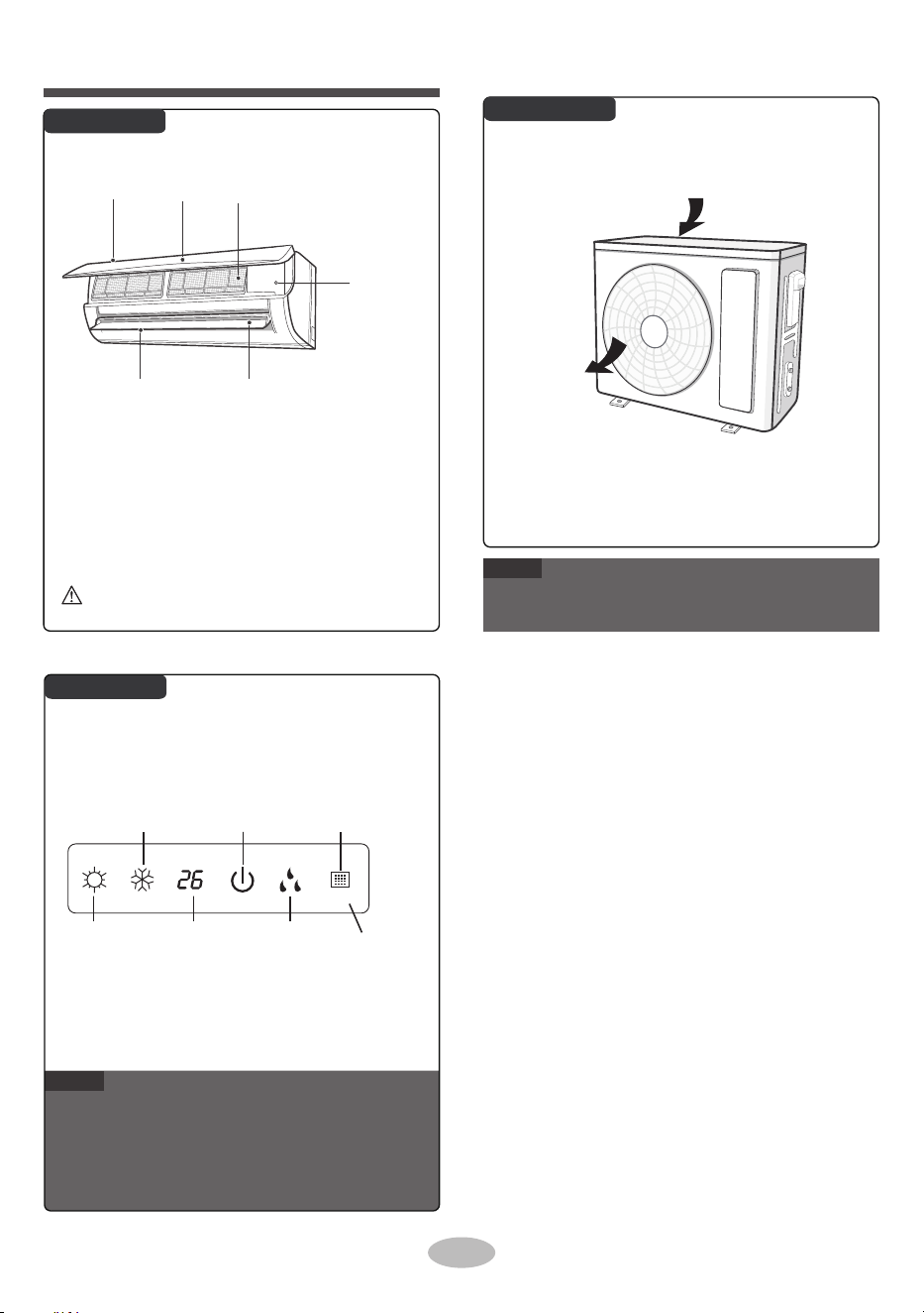
●
●
●
Actual product may be different from above graphics,
please refer to actual product.
This is the general introduction and the color of
indicator is only for reference. Please refer to the
actual display.
Display content may be different from the actual.
Please refer to the actual display.
■
If remote controller is lost or damaged, please
use aux. button to turn on or turn off the air
conditioner. The operation in details is as
below: As shown in the figure, open panel and
press aux. button to turn off the air conditioner.
When the air conditioner is turned on, it will
operate under auto mode.
6
Nome das peças
Unidade Interior
Unidade Exterior
Visor
NOTA
NOTA
Botão auxiliar
FiltroPainelEntrada de ar
Persiana horizontal
Saída de ar
Entrada de ar
Saída de ar
Indicador de
aquecimento
Indicador de
temperatura
Indicador de
arrefecimento
Indicador de
potência
Janela do
receptor
Indicador de
secagem
Visor
O produto real poderá ser diferente dos gráficos acima apresentados.
Consulte o produto real.
O conteúdo do visor ou a posição poderá ser diferente dos gráficos
acima apresentados. Consulte o produto real
Se perder ou danificar o controlo remoto, utilize o
botão aux. para ligar ou desligar o ar condicionado.
A operação é descrita nos detalhes abaixo: Como
demonstrado na figura Painel aberto, prima o botão
aux. para ligar ou desligar o ar condicionado.
Quando o ar condicionado é ligado, irá funcionar no
modo automático.
Esta é a introdução geral e a cor do indicador é apenas para referência.
Por favor, consulte a real.
AVISO
Use o objeto isolante para pressionar o botão auto
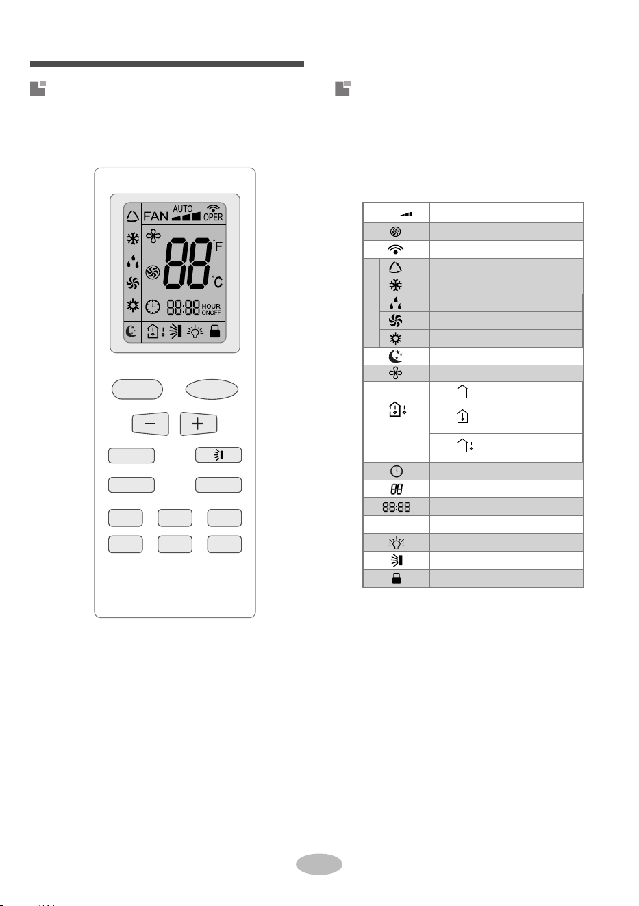
FAN (Ventilador)
ON/OFF
(Ligar/desligar)
AUTO (Modo Automático)
ON/OFF (Ligar/desligar) MODO
Ventilador-X
TURBO
Temperatura
TEMPORIZADOR
DESLIGADO
SUSPENSÃO
LUZ
VENTILADOR
RELÓGIO
TEMPORIZADOR
LIGADO
Definição de temperatura
Função de ventilador X
Definição de temperatura
Temp. ambiente exterior
Temp. ambiente interior
Modo de suspensão
Relógio
Modo automático
Definição de hora
TEMPORIZADOR LIGADO/DESLIGADO
Modo de frio
Modo de secador
Modo de ventilador
Luz
Oscilação para cima e para baixo
Bloqueio para crianças
Enviar sinal
Modo Turbo
Modo de calor
Modo de funcionamento
Definição da velocidade do ventilador
Tipo de
visualização da
temp.
7
Introdução para botões no controlo
remoto
Botões no controle remoto
Operação e introdução do controlo remoto
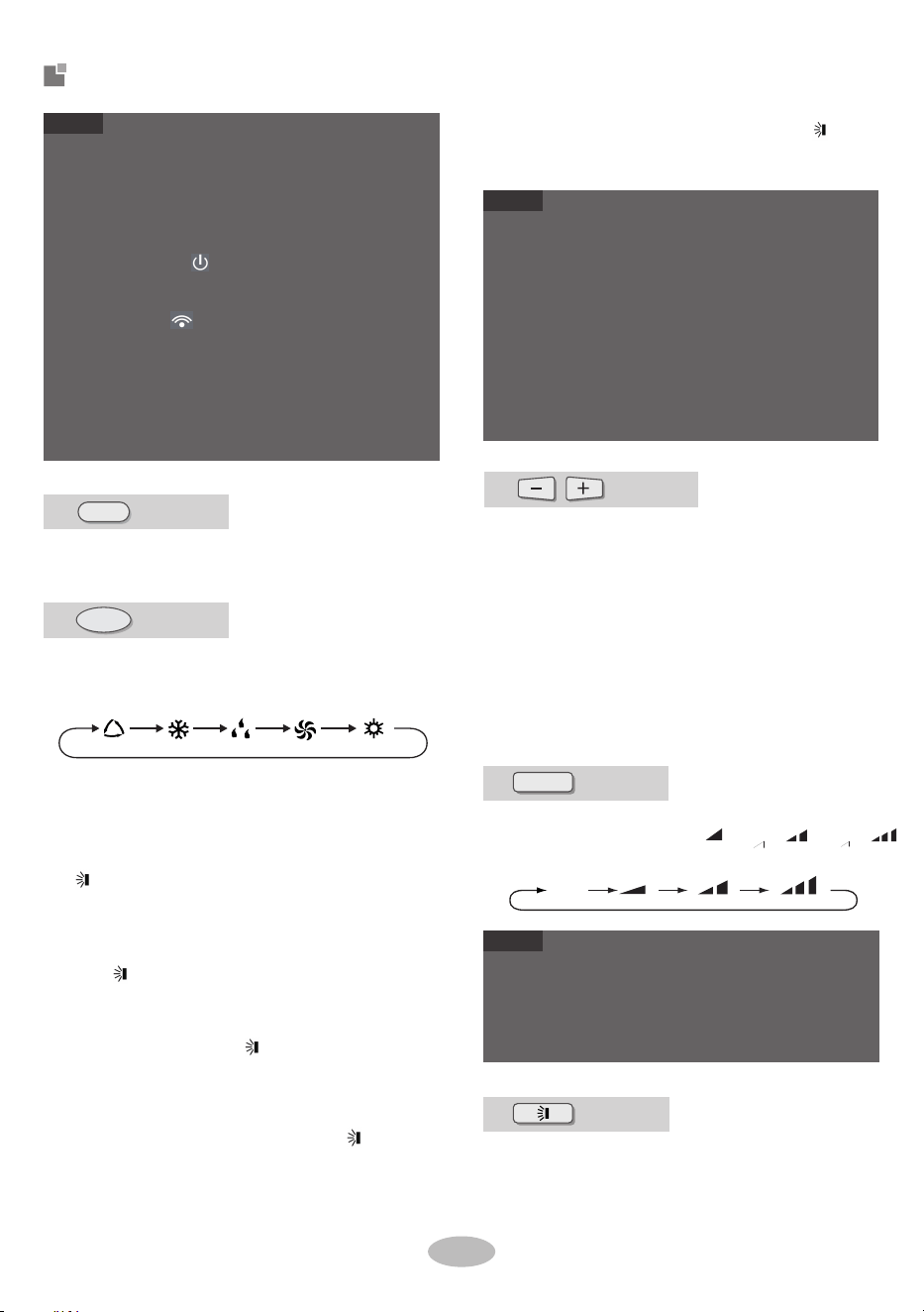
●
●
●
●
●
●
●
Press this button to turn on the unit. Press this button
again to turn off the unit.
When selecting auto mode, air conditioner will
operate automatically according to ambient tem-
perature. Set temperature can't be adjusted and
will not be displayed as well. Press "FAN" button
can adjust fan speed. Press " " button can
adjust fan blowing angle.
When selecting cool mode, air conditioner will
operate under cool mode. Press "+" or "-"
button to adjust set temperature. Press "FAN"
button to adjust fan speed. Press " nottub "
to adjust fan blowing angle.
When selecting dry mode, the air conditioner
operates at low speed under dry mode. Under
dry mode, fan speed can't be adjusted. Press
" " button to adjust fan blowing angle.
When selecting fan mode, the air conditioner will
only blow fan, no cooling and no heating. Press
"FAN" button to adjust fan speed. Press " "
button to adjust fan blowing angle.
This is a general use remote controller. It could be
used for the air conditioner with multifunction. For the
functions which the model doesn't have, if press the
corresponding button on the remote controller, the
unit will keep the original running status.
After putting through the power, the air conditioner
will give out a sound. Power indicator " " is ON.
After that, you can operate the air conditioner by
using remote controller.
Under on status, pressing the button on the remote
controller, the signal icon " " on the display of
remote controller will blink once and the air condition-
er will give out a sound, which means the signal has
been sent to the air conditioner.
Press "+" or "-" button once increase or decrease
set temperature 1℃(℉). Holding "+" or "-" button, 2s
later, set temperature on remote controller will
change quickly. On releasing button after setting is
finished, temperature indicator on indoor unit will
change accordingly. (Temperature can’ t be adjust-
ed under auto mode)
When setting TIMER ON, TIMER OFF or CLOCK,
press "+" or "-" button to adjust time. (Refer to
CLOCK, TIMER ON, TIMER OFF buttons).
●
●
●
●
For preventing cold air, after starting up heat mode,
indoor unit will delay 1~5 minutes to blow air (Actual
delay time depends on indoor ambient temperature).
Set temperature range from remote controlle r:
16~30℃(61-86℉).
This mode indicator is not available for some models.
Cooling only unit won't receive heat mode signal. If
setting heat mode with remote cont roller, press
ON/OFF button can't start up the unit.
●
When selecting heat mode, the air conditioner
operates under heat mode. Press "+" or "-"
button to adjust set temperature. Press "FAN"
button to adjust fan speed. Press " " button
to adjust fan blowing angle.
Botão
Botão
VENTILAÇÃO
AUTOMÁTICO
REFRIGERAÇÃO SEAGEM
AQUECIMENTO
Pressione este botão para selecionar o modo de funcionamento
pretendido.
Introdução para botões no
controlo remoto
8
Auto (Automático)
●
●
VENTILADOR
Botão
Ao pressionar este botão pode definir a velocidade do ventilador de maneira
circular como: Auto (AUTO), reduzido ( ), médio ( ), elevado ( ).
Botão
Botão
Pressionar este botão para selecionar o ângulo de oscilação para
cima e para baixo. O ângulo de sopro da ventilação pode ser
selecionado de maneira circular, como demonstrado abaixo:
A velocidade de ventilação no modo de secador é reduzida.
NOTA
NOTA
NOTA
Na velocidade AUTO, o ar condicionado irá selecionar
a velocidade de ventilação adequada de forma
automática de acordo com a temperatura ambiente.
ON/OFF
(Ligar/desligar)
Pressionar o botão "+" ou "-" uma vez irá aumentar ou diminuir a
temperatura definida em 1 ºC (°F). Manter premido durante 2
segundos ou mais o botão "+" ou "-", irá alterar a temperatura no
controlo remoto mais rapidamente. Libertar o botão depois de
definir, o indicador de temperatura da unidade de interior irá alterar
em conformidade. (A temperatura não pode ser ajustada no modo
automático)
Durante a definição de TIMER ON (Temporizador ligado), TIMER
OFF (Temporizador desligado) ou CLOCK (Relógio), prima o botão
"+" ou "-" para ajustar a hora. (Consulte os botões CLOCK, TIMER
ON, TIMER OFF)
Pressione o botão para ligar a unidade. Pressione novamente este
botão para desligar a unidade.
• Para evitar deitar ar frio depois de iniciado o modo de
calor, a unidade de interior irá atrasar a emissão de ar entre
1 e 5 minutos (o tempo de atraso real dependerá da
temperatura ambiente no interior).
• Intervalo de temperatura definido a partir do controlo
remoto: 16~30 °C (61-86ºF).
• Este indicador de modo não está disponível em alguns
modelos.
• A unidade de arrefecimento apenas não irá receber o sinal
do modo de calor. Se definir o modo de calor com o
controlo remoto, pressionar o botão ON/OFF (Ligar/desli-
gar) não irá iniciar a unidade.
• Isto é um controlo remoto de uso geral, pode ser utilizado
para as unidades de ar condicionado multifuncional. Para
as funções, que não estejam disponíveis no modelo, se
premir o botão correspondente no controlo remoto a
unidade manterá o estado de funcionamento original.
• Depois de ligar a alimentação, o ar condicionado emite um
som. O indicador " " está LIGADO. Depois, poderá
utilizar o ar condicionado através do controlo remoto.
• No estado ligado, pressione o botão no controle remoto, o
ícone de sinal " " no visor do controle remoto piscará
uma vez e o ar condicionado emitirá um som, o que
significa que o sinal foi enviado ao ar condicionado.
• Quando o modo automático é selecionado, o ar
condicionado irá funcionar automaticamente de acordo
com temperatura ambiente. A temperatura definida não
pode ser ajustada. Pressione o botão "FAN" (Ventilador)
para ajustar a velocidade de ventilação. Pressione o botão
" " para ajustar o ângulo de sopro de ventilação.
• Quando o modo de frio é selecionado, o ar condicionado
irá funcionar no modo de frio. Pressione o botão "+" ou "-"
para ajustar a temperatura definida. Pressione o botão
"FAN" para ajustar a velocidade de ventilação. Pressione o
botão " " para ajustar o ângulo de sopro da ventilação.
• Quando é selecionado o modo dry, o ar condicionado
funciona a uma velocidade baixa no modo de secador. No
modo de secador, a velocidade de ventilação não pode ser
ajustada. Pressione o botão " " para ajustar o ângulo de
sopro da ventilação.
• Quando é selecionado o modo fan, o ar condicionado
apensa irá funcionar com a ventilação, sem frio ou calor.
Pressione o botão "FAN" (Ventilador) para ajustar a
velocidade do ventilador. Pressione o botão " " para
ajustar o ângulo de sopro da ventilação.
Quando é selecionado o modo heat, o ar condicionado
funciona no modo de calor. Pressione o botão "+" ou "-" para
ajustar a temperatura definida. Pressione o botão "FAN" para
ajustar a temperatura definida. Pressione o botão " " para
ajustar o ângulo de sopro da ventilação.
MODO
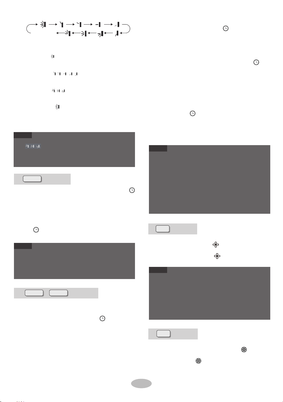
●
●
●
●
When s electing " ", air conditioner is blowing
fan automatically. Horizontal louver will automat-
ically swing up & down at maximum angle. When
selecting
、 、 "
blowing fan at fixed position. Horizontal louver
will stop at the fixed position.
When selecting "
、
、
", air conditioner
is blowing fan at fixed angle. Horizontal louver
will send air at the fixed angle.
Hold " "button above 2s to set your required
swing angle. When reaching your required
angle, release the button.
●
“
、
、
" may not be available. When air
condi-
tioner receives this signal, the air conditioner
will blow fan automatically.
● TIMER ON button
"TIMER ON" button can set the time for timer
on. After pressing this button, " " icon disap-
pears and the word "ON" on remote controller
blinks. Press "+" or "-" button to adjust TIMER
ON setting. After each pressing"+" or "-" button.
TIMER ON setting will increase or decrease
1min. Holding "+" or "-" button, 2s later, the time
will change quickly until reaching your required
time.
●
Press "TIMER ON" to confirm it. The word "ON"
will stop blinking. " " icon resumes displaying.
Cancel TIMER ON: Under the condition that
TIMER ON is started up, press "TIMER ON"
button to cancel it.
TIMER OFF button
"TIMER OFF" button can set the time for timer
off. After pressing this button, " "icon disap-
pears and the word "OFF" on remote
controller
blinks. Press Press "+" or "-" button to adj ust
TIMER OFF setting. After each pressing "+" or
"-" button, TIMER OFF setting will increase or
decrease 1min. Holding "+" or "-" button, 2s
later, the time will change quickly until reaching
your required time.
Press "TIMER OFF" and the word "OFF" will
stop blinking. " " icon resumes displaying.
Under the condition that TIMER OFF is started
up, press "TIMER OFF" button to cancel it.
●
●
●
Under on and off status, you can set TIMER OFF or
TIMER ON simultaneously.
Before setting TIMER ON or TIMER OFF, please
adjust the clock time.
After starting up TIMER ON or TIMER OFF, set the
constant circulating valid. After that, air conditioner
will be turned on or turned off according to setting
time. ON/OFF but ton has no effect on setting. If you
don 't need this function, please use remote control-
ler to cancel it.
●
●
When X-FAN function is on, if the air conditioner is
turned off, indoor fan will still operate at low speed
for a while to blow the residual water inside the air
duct.
During
X-FAN
operation, press X-FAN button to turn
off
X-FAN
function. Indoor fan will stop operation
immediately.
Sem visualização (as grelhas horizontais
param na posição em que estiverem)
Botão
Botão
Botão/
Ventilador-X
RELÓGIO
TEMPORIZADOR
LIGADO
Pressione este botão no modo de frio e de secador para iniciar a
função de ventilador X. O ícone " " será apresentado no
controlo remoto. Prima novamente este botão para cancelar a
função de ventilador X e o ícone " " desaparecerá.
TEMPORIZADOR
DESLIGADO
TURBO
Botão
NOTA
NOTA
NOTA
NOTA
9
Pressione este botão para definir a hora do relógio. O ícone " "
no controlo remoto irá piscar. Pressione o botão ''+'' ou ''-'' dentro de
5 segundos para definir a hora do relógio. Cada pressão do botão
''+'' ou ''-'' irá aumentar ou diminuir 1 minuto no relógio. Se
mantiver premido o botão ''+'' ou ''-'' durante mais de 2 segundos, a
hora será alterada rapidamente. Liberte o botão quando alcançar a
hora pretendida. Pressione o botão ''CLOCK'' para confirmar a hora.
O ícone " " deixa de piscar.
● A hora do relógio adota o modo de 24 horas.
● O intervalo entre as duas operações não pode exceder 5
segundos. Caso contrário, o controlo remoto irá sair do
estado de definição. A operação para o TIMER
ON/TIMER OFF é igual.
No modo COOL ou HEAT, pressione este botão para mudar para o
modo COOL rápido ou HEAT rápido. O ícone " " é apresentado
no controlo remoto. Pressione novamente este botão para sair da
função turbo e o ícone " " irá desaparecer.
• No estado ligado ou desligado, pode definir o TIMER
OFF ou TIMER ON em simultâneo.
• Antes de definir o TIMER ON ou TIMER OFF, ajuste a
hora do relógio.
• Depois de iniciar o TIMER ON ou TIMER OFF, defina a
constante em circulação válida. Depois disso, o ar
condicionado será ligado ou desligado de acordo com a
hora definida. O botão ON/OFF não produz qualquer
efeito na definição. Se não precisar desta função, utilize o
controlo remoto para a cancelar.
• Quando a função de ventilador X está ligada, se o ar
condicionado for desligado, o ventilador do interior
continuará a funcionar a uma velocidade baixa durante
algum tempo para evacuar a água residual dentro da conduta
de ar.
• Durante o funcionamento do ventilador X, prima o botão
X-FAN para desligar a função de ventilador X. O ventilador
do interior irá parar de funcionar imediatamente.
• Ao selecionar " ", a ventilação do ar condicionado está
automática. A grelha horizontal irá oscilar automatica-
mente para cima e para baixo no ângulo máximo.
• Ao selecionar " ", a ventilação do ar
condicionado está numa posição fixa. A grelha horizontal
irá parar na posição fixa.
• Ao selecionar " " a ventilação do ar condicionado
está num ângulo fixo. A grelha horizontal emite ar a um
ângulo fixo.
• Manter o botão " " pressionado durante mais de 2
segundos irá definir o ângulo de oscilação pretendido. Ao
alcançar o ângulo pretendido, liberte o botão.
Pressione em "TIMER ON" para confirmar. A palavra
''ON'' irá parar de piscar. O ícone " " voltará a ser
apresentado. Cancelar o TIMER ON: sob a condição de o
TIMER ON ter sido iniciado, pressione o botão "TIMER
ON" para o cancelar.
• Botão TIMER OFF
O botão ''TIMER OFF'' define a hora do temporizador para
desligar. Depois de pressionar este botão, o ícone " "
desaparece e a palavra ''OFF'' no controlo remoto começa
a piscar. Pressione o botão ''+'' ou ''-'' para ajustar a
definição TIMER OFF. Cada pressão do botão ''+'' ou ''-'', a
definição TIMER OFF irá aumentar ou diminuir 1 minuto.
Manter o botão ''+'' ou ''-'' durante 2 segundos ou mais irá
alterar o tempo rapidamente até alcançar a hora
pretendida.
Pressione em ''TIMER OFF'' para a palavra ''OFF'' parar de
piscar. O ícone " " voltará a ser apresentado. Sob a
condição de o TIMER OFF ter sido iniciado, pressione o
botão "TIMER OFF" para o cancelar.
• Botão TIMER ON
O botão "TIMER ON" define a hora do temporizador para
ligar. Depois de premir este botão, o ícone " " desaparece e
a palavra ''ON'' no controlo remoto começa a piscar. Pressione
o botão ''+'' ou ''-'' para ajustar a definição TIMER ON. Cada
pressão do botão ''+'' ou ''-'', a definição TIMER ON irá
aumentar ou diminuir 1 minuto. Manter o botão ''+'' ou ''-''
durante 2 segundos ou mais irá alterar o tempo rapidamente
até alcançar a hora pretendida.
• " " poderá não estar disponível. Quando o ar
condicionado recebe este sinal, aquele irá iniciar o
ventilador automaticamente.
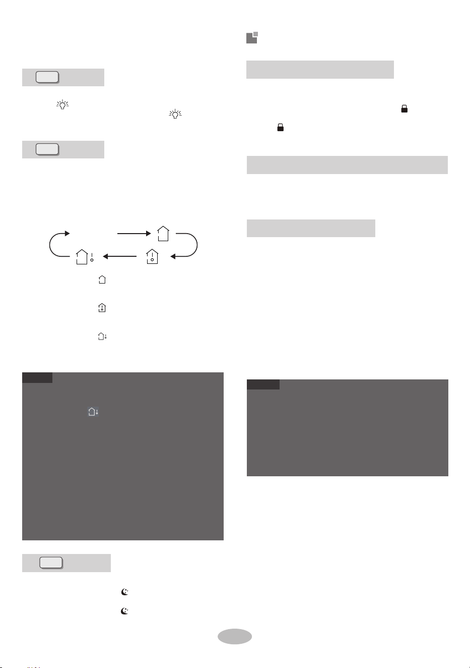
●
●
●
●
●
●
●
ambient temperature on indoor unit's display. The
setting on remote controller is selected circularly
as below:
Under OFF status, press "-" and "MODE" buttons
simultaneously to switch temperature display
between
℃ and ℉.
Outdoor temperature display is not available for some
models. At that time, indoor unit receives " "
signal, while it displays indoor set temperature.
It
's defaulted to display set temperature when turning
on the unit. There is no display in the remote control-
ler.
Only for the models whose indoor unit has dual-8
display.
When selecting displaying of indoor or outdoor ambi-
ent temperature, indoor temperature indicator
displays corresponding temperature and automatical-
ly turn to display set temperature after three or five
seconds.
When selecting " " or no display with remote
controller, temperature indicator on indoor unit
displays set temperature.
When selecting " " with remote controller, tem-
perature indicator on indoor unit displays indoor
ambient temperature.
When selecting " " with remote controller,
temperature indicator on indoor unit displays
outdoor ambient temperature.
By pressing this button, you can see indoor set tem-
perature, indoor ambient temperature or outdoor
again to exit turbo function and " " icon will
disappear.
Under COOL or HEAT mode, press this button to
start up sleep function. " " icon is displayed on
remote controller. Press this button again to
cancel sleep function and " " icon will disappear.
Press "+" and "-" simultaneously to turn on or turn
off child lock function. When child lock function is
on, " " icon is displayed on remote controller. If
you operate the
remote controller, the "
" icon
will blink three times without sending signal to the
unit.
●
●
The auto clean function can only work under normal
ambient temperature. If the room is dusty, clean it
once a month; if not, clean it once every three
months. After the auto clean function is turned on,
you can leave the room. When auto clean is finished,
the air conditioner will enter standby status.
This function is only available for some models.
Under unit off status, hold "MODE" and "FAN"
buttons simultaneously for 5s to turn on or turn off
the auto clean function. When the auto clean func-
tion is turned on, indoor unit displays "CL". During
the auto clean process of evaporator, the unit will
perform fast cooling or fast heating. There may be
some noise, which is the sound of flowing liquid or
thermal expansion or cold shrinkage. The air con-
ditioner may blow cool or warm air, which is a
normal phenomenon. During cleaning process,
please make sure the room is well ventilated to
avoid affecting the comfort.
10
Função de alteração da exibição da temperatura
Sem
visualização
Introdução de funções para
botões de combinação
Botão
Função de bloqueio para crianças
SUSPENSÃO
Botão
Temperatura
Botão
LUZ
Prima este botão para desligar a luz do visor na unidade de interior.
O ícone " " desaparece do controlo remoto. Prima novamente
este botão para ligar a luz do visor. O ícone " " será
apresentado.
NOTA
Função de limpeza automática
NOTA
• A função de auto-limpeza só pode funcionar sob
temperatura ambiente normal. Se a sala estiver poeirenta,
limpá-la uma vez por mês; se não, limpá-la uma vez de
três em três meses. Após a função de auto-limpeza estar
ligada. Pode sair da sala. Quando a função de auto-limpeza
estiver terminada, o ar condicionado entrará em estado de
espera.
• Esta função só está disponível para alguns modelos.
Sob o estado de unidade desligada, mantenha os botões "MODE"
e "FAN" simultaneamente durante 5s para ligar ou desligar a
função de limpeza automática. Quando a função de auto-limpeza
é ligada, a unidade interior exibe "CL". Durante o processo de
auto-limpeza do evaporador, a unidade realizará um rápido
arrefecimento ou aquecimento rápido. Pode haver algum ruído,
que é o som de líquido fluente ou expansão térmica ou
encolhimento a frio. O ar condicionado pode soprar ar frio ou
quente, o que é um fenómeno normal. Durante o processo de
limpeza, certifique-se de que a sala está bem ventilada para
evitar afetar o conforto.
Se pressionar este botão, poderá visualizar a temperatura definida
interior, a temperatura ambiente interior ou a temperatura ambiente
exterior no visor da unidade interior. A definição no controlo
remoto é selecionada em circuito como apresentado abaixo.
No estado DESLIGADO, prima o botão "-" e o botão "MODE" em
simultâneo para alterar entre ºC e ºF.
No modo COOL ou HEAT, pressione este botão para ligar a
função de suspensão. O ícone " " é apresentado no controlo
remoto. Pressione novamente este botão para cancelar a
função de suspensão. O ícone " " irá desaparecer.
• A apresentação da temperatura exterior não está disponível
em alguns modelos. Atualmente, a unidade de interior
recebe o sinal " ", ao mesmo tempo que apresenta a
temperatura interior definida.
• Está predefinido para apresentar a temperatura definida
quando a unidade é ligada. Não existe apresentação no
controlo remoto.
• Isto só está disponível nos modelos cujas unidades
interiores tenham um visor duplo-8.
• Ao selecionar a apresentação da temperatura ambiente
interior ou exterior, o indicador de temperatura interior
apresenta a temperatura correspondente e muda
automaticamente para a apresentação da temperatura
definida após três ou cinco segundos.
• Quando seleciona " " ou sem visualização no controlo
remoto, o indicador de temperatura na unidade interior
apresenta a temperatura definida.
• Quando seleciona " " com o controlo remoto, o
indicador de temperatura na unidade interior apresenta a
temperatura ambiente.
• Quando seleciona " " com o controlo remoto, o
indicador de temperatura na unidade interior apresenta a
temperatura ambiente exterior.
Pressione os botões "+" e "-" em simultâneo para ativar ou
desativar a função de bloqueio para crianças. Quando a função
do bloqueio para crianças está ativada, o ícone " " é
apresentado no controlo remoto. Se operar o controlo remoto,
o ícone " " irá piscar três vezes sem enviar qualquer sinal
para a unidade.
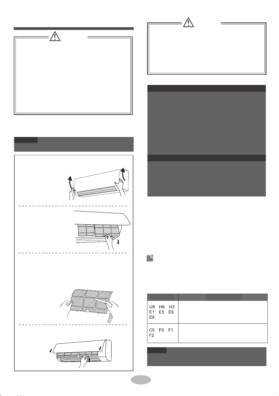
2.
■
2.
■
4.
■
■
■
1.
Check whether air inlets and air outlets are bl-
3.
●
●
●
Pull out the panel
to a certain angle
as shown in the
fig.
●
4.
1.
1.
2.
3.
Remove the filter as
indicated in the fig.
2.
1.
If there're other error codes, please contact qu-
alified professionals for service.
ocked.
Disconnect power supply.
Clean filter and indoor unit’s panel.
Clean surface of indoor unit
When the surface of indoor unit is dirty, it is
recomm-ended to use a soft dry cloth or wet cloth
to wipe it.
Many packing materials are recyclable mate-
5.Check whether drainage pipe is damaged.
Check whether mounting bracket for outdo
or
unit is damaged or corroded. If yes, please
contact dealer.
Check whether air switch, plug and socket are
in good condition.
3.Check whether filter is clean.
Check whether mounting bracket for outdoor
unit is damaged or corroded . If yes, please
contact dealer.
The filter should be cleaned every three months .
If there is much dust in the operation environme-
nt, clean frequency can be increased.
After removing the filter, do not touch fins to
avoid injury.
Do not use fire or hair dryer to dry the filter to
avoid deformation or fire hazard.
When air conditioner status is abnor mal, tempe-
rature indicator on indoor uni t will blink to display
corresponding error code. Please refer to below
list for identification of error code.
rials. Please dispose them in appropriat e
recycling unit.
If you want to dispose the air conditioner, please
contact local dealer or consultant service center
for the correct disposal method.
Use dust catcher or water to clean the
filter.
When the filter is very dirty, use the
water (below 45℃) to clean it , and then put
it in a shady and cool place to dry.
Turn off the air conditioner and disconnect the
power before cleaning the air conditioner to av-
oid electric shock.
■
Do not wash the air conditioner with water to
avoid electric shock.
■
Do not use volatile liquid to clean the air
conditioner.
Do not use liquid or corrosive detergent to clean
the appliance and do not splash water or other
liquid onto it , otherwise, it may damage the
plastic components , even cause electric shock.
, , ,
, , ,
, , ,
11
Limpeza e manutenção
ATENÇÃO
ATENÇÃO
Limpar o filtro
Não remova o painel para o limpar.
Código de erro
NOTA
Abrir o painel
AVISO
Remover o filtro
Aviso de recuperação
Instalar o filtro
Limpar o filtro
Instalar o filtro e depois fechar bem a tampa do painel.
AVISO: Verificação antes da utilização
AVISO: Verificação depois da utilização
Contacte profissionais qualificados para
proceder à assistência.
1. Desligue a alimentação.
2. Limpe o filtro e o painel da unidade de interior.
3. Verifique se o suporte de instalação da unidade de exterior
está danificado ou corroído. Se sim, entre em contacto
com o vendedor.
Se existirem outros códigos de erro, contacte
profissionais qualificados para proceder à assistência.
Resolução de problemas
Remova o filtro como
indicado na figura.
Pode ser eliminado depois de reiniciar a
unidade. Se não, contacte profissionais
qualificados para proceder à assistência.
1. Muitos dos materiais de embalagem são recicláveis.
Elimine-os na unidade de reciclagem apropriada.
2. Se pretende eliminar o ar condicionado, entre em contacto
com o vendedor local ou o centro de atendimento para saber
qual é o método de eliminação correto.
1. Verifique se as entradas e saídas de ar estão bloqueadas.
2. Verifique se a ficha e a tomada estão em boas
condições.
3. Verifique se o filtro está limpo.
4. Verifique se o suporte de instalação da unidade de
exterior está danificado ou corroído. Se sim, entre em
contacto com o vendedor.
5. Verifique se o tubo de drenagem está danificado.
Quando o estado do ar condicionado está anómalo, o indicador de
temperatura na unidade de interior irá piscar para apresentar o
código de erro correspondente. Consulte a lista abaixo para
identificar o código de erro.
● Utilize um espanador ou água para o limpar
● Quando o filtro estiver muito sujo, utilize água (abaixo
de 45 ℃) para o limpar e, em seguida, coloque-o num
local fresco e seco para secar.
Código de erro
■ O filtro deve ser removido a cada três meses. Se existir
demasiado pó no ambiente de funcionamento, a
frequência de limpeza pode ser aumentada.
■ Depois da remoção do filtro, não tocar nas lâminas para
evitar lesões.
■ Não utilizar fogo ou um secador de cabelo para secar o
filtro para evitar deformação ou o perigo de incêndio.
Retire o painel até um
certo ângulo, como
demonstrado na figura.
Limpar a superfície da unidade de interior
Quando a superfície da unidade de interior estiver suja, é
recomendado utilizar um pano suave seco ou molhado para a limpar.
■ Desligue o ar condicionado e corte a alimentação antes
de limpar o ar condicionado para evitar choque elétrico.
■ Não limpe o ar condicionado com água para evitar
choque elétrico.
■ Não utilize líquidos voláteis para limpar o ar
condicionado.
■ Não utilize líquidos e detergentes corrosivos para limpar
o aparelho e não salpique água ou outros líquidos no
mesmo, caso contrário, poderá danificar os componentes
plásticos e, até, causar choque elétrico.
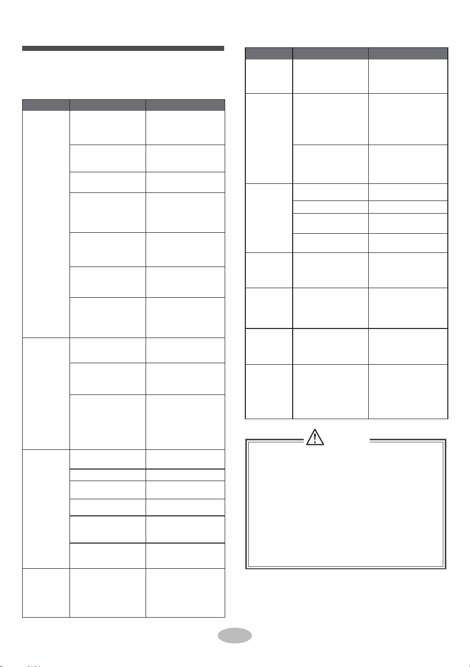
Whether remote co-
ntroller is within the
signal receiving range?
Select proper angle
and point the remote
controller at the rece-
iving window on indoor
unit.
Whether remote co-
ntroller is pointing at
the receiving window?
Check the batteries.
seirettab for ewope ht fI
is to o low , please rep-
lace them.
it ma or,
.
When below phenomenon occurs,please turn
off air conditioner and disconnect power immedi-
ately, and then contact the dealer or qualified
professionals for service.
■
● Power cord is overheating or damaged.
There’s abnormal sound during operation.
Air switch trips off frequently.
Air conditioner gives off burning smell.
Indoor unit is leaking.
Ask professional to
replace air switch or fuse.
Ask professional to
replace it.
Do not repair or refit the air conditioner by yourself.
If the air conditioner operates under abnormal
conditions, it may cause malfunction, electric
shock or fire hazard.
Because indoor air
is cooled rapidly.
After a while, indoor
temperature and hu-
midity will be decrease
and mist will disappe
ar.
Odours are
emitted
Whether it's interfered
severely (such as sta-
tic electricity, stable
voltage?)
Set tempe-
rature can’t
be adjusted
Indoor unit
can’t receive
remote co-
ntroller’s si-
gnal or remote
controller has
no action.
Cooling
(heating)
effect is
not good.
Air conditi-
oner operates
abnormally
Outdoor uni
t
has vapor
“Water
flowing”
noise
After
reaching to set
temperature,
indoor
unit will stop blowing
out air.
No air
emitted
from indoor
unit
Cracking
noise
Wait until power
recovery.
Air
conditioner
can’t operate
■
■
Mist is emi-
tted from
indoor unit’s
air outlet
●
●
●
●
Whe inte-
devi
ther there’s
rference, such as
thunder, wireless
ces, etc.
The nd
of refriger
in
a normal on
noise is the sou
ant flowing
side the unit, which is
phenomen
Pull out the plug.
Reinsert the plug after
about 3min, and then
turn on the unit again.
During defrosting
under heating mode,
y generate vap
which is a normal
phenomenon.
This is the sound of
friction caused by
expansion and
or
contraction of panel
or other parts due to
the change
of temp-
erature.
Elimine a origem do odor.
Limpe o filtro.
A temperatura não pode ser
ajustada no modo automático.
Mude o modo de
funcionamento se precisar
ajustar a temperatura.
A unidade está a operar no
modo automático?
A temperatura pretendida
excede o intervalo de definição
de temperatura?
A voltagem é demasiado baixa?
Aguarde que a tensão regresse ao
normal.
O filtro está sujo? Limpe o filtro.
Ajuste a temperatura para o
intervalo correto.
Desligue a alimentação, volte a
ligar a alimentação e ligue a
unidade novamente.
Qual a origem do odor, como
mobiliário, cigarros, etc.
Intervalo de definição de
temperatura: 16 °C ~ 30 °C.
A temperatura definida está
dentro do intervalo correto?
A porta e a janela estão abertas?
Feche as portas e as janelas.
O modo de aquecimento
está ligado?
O ar condicionado está ligado
ou desligado agora mesmo?
O ar condicionado está ligado
ou desligado agora mesmo?
Remova os obstáculos.
A sensibilidade do controlo
remoto está baixa; a exibição
está indefinida ou não existe
exibição?
Nenhuma exibição durante a
operação do controlo remoto?
Verifique se o controlo remoto
apresenta danos. Se sim,
substitua-o.
Aproxime o controlo remoto da
unidade de interior.
Remova os obstáculos.
No modo de aquecimento, a
temperatura interior atingiu a
temperatura definida?
De modo a evitar a emissão de ar
frio, a unidade de interior irá
iniciar após um atraso de alguns
minutos, sendo isto um
fenómeno normal.
O modo de aquecimento é
virado ao contrário?
Falha de alimentação?
A ficha está solta?
Reinserir a ficha.
Existe uma avaria na fiação?
A unidade reiniciou
imediatamente depois de parar o
funcionamento?
Esperar 3min, e depois ligar
novamente a unidade.
A definição de função do
controlo remoto está correta?
Reinicie a função.
A temperatura e a humidade
interiores estão elevadas?
O alcance da recepção do sinal
é de 8m.
Existem obstáculos?
Tem uma lâmpada fluorescente
na área?
A entrada de ar ou a saída de ar
da unidade de interior está
bloqueada?
Itens para verificação Solução
Fenómeno
Fenómeno
Solução
Itens para verificação
Verifique os itens abaixo antes de solicitar a
manutenção. Se, ainda assim, não for possível
eliminar a avaria, entre em contacto com o vendedor
local ou profissionais qualificados.
Itens verificados antes da manutenção
Análise geral dos fenómenos
ATENÇÃO
O interruptor de ar desliga-se
ou o fusível queima-se?
O ar condicionado
funciona de forma
anormal
Ruído de "água
corrente"
Existem interferências, como
trovões, dispositivos sem fios,
etc.?
A temperatura
definida não pode
ser ajustada
Peça a um profissional para
substituir o disjuntor ou o fusível.
Verifique as pilhas. Se as pilhas
estiverem gastas, substitua-as.
Esperar até à recuperação de
energia.
Durante o descongelamento no
modo de calor, poderá gerar
vapor, sendo um fenómeno
normal.
Depois de alcançar a temperatura
definida, a unidade de interior
para de emitir ar.
É emitida uma
bruma da saída de
ar da unidade de
interior
O controlo remoto está a apontar
para a janela de receção?
Este é o som da fricção causada
pela expansão e/ou a contração do
painel ou de outras peças devido à
alteração da temperatura.
O efeito de
arrefecimento
(aquecimento)
não é bom.
■ Quando acontecerem os fenómenos descritos abaixo, desligue o ar
condicionado e desligue da tomada elétrica imediatamente e, em
seguida, entre em contacto com o vendedor ou com profissionais
qualificados para procederem à assistência.
● O cabo elétrico está em sobreaquecimento ou danificado.
● Existe um som anormal durante o funcionamento.
● O disjuntor está sempre a disparar.
● O ar condicionado emite um cheiro a queimado.
● A unidade de interior apresenta fugas.
■ Não repare ou volte a instalar o ar condicionado sozinho.
■ Se o ar condicionado estiver a funcionar sob condições anormais,
pode causar avarias, choque elétrico ou perigo de incêndio.
Os odores são
emitidos
A unidade de
interior não recebe o
sinal do controlo
remoto ou o
controlo remoto não
produz ação.
Selecione o ângulo adequado e
aponte o controlo remoto à janela
de receção na unidade de interior.
O ruído é o som do fluido
refrigerante a fluir dentro da
unidade, o que é um fenómeno
normal.
O ar no interior é arrefecido
rapidamente. Passado algum
tempo, a temperatura interior e a
humidade irão diminuir e a bruma
desaparecerão.
Ruído de quebra
Peça ao profissional para
substituí-lo.
Nenhum ar emitido
da unidade de
interior
A unidade exterior
tem vapor
O ar condicionado
não funciona
O controlo remoto está dentro
do alcance de receção do sinal?
Existe intervenção severa (como
eletricidade estática, voltagem
estável)?
Remova a ficha da tomada.
Volte a inserir a ficha após cerca
de 3 minutos e, em seguida, ligue
a unidade.
12

■
■
■
When refrigerant needs to be recovered
during relocating or repairing the unit, be
When installing or relocating the unit, be s-
ure to keep the refrigerant
circuit free from
air or substances other than the specified
refrigerant.
Any presence of air or other foreign substance
in the refrigerant circuit will cause
system pre-
ssure rise or compressor rupture, resulting
in injury.
When in
stalling or moving this unit, do not
charge the refrigerant which is not comply
with that on the nameplate or unqualified
refrigerant.
Otherwise, it may cause abnormal operation,
wrong action, mechani
cal malfunction or even
serious safety accident.
■
■
■
■
■
When installing the unit, make sure that co-
nnection pipe is securely connected before
the compressor starts running.
If compressor starts running when stop valve
is open and connection pipe is not yet conne-
cted, air will be sucked in and cause pressure
rise or compressor rupture, resulting in injury.
Electric wires with insufficient capacity, wrong
wire connections and insecure wire terminals
may cause electric shock or fire.
1 minute.
sure that the unit is running in cooling mode.
Then, fully close the valve at high pressure
side (liquid valve). About 30-40 seconds later,
fully close the valve at low pressure side
(gas valve), immediately stop the unit and
disconnect power. Please note that the time
for refrigerant recovery should not exceed
Use the specified types of wires for electrical
connections between the indoor and outdoor
units. Firmly clamp the wires so that their te-
rminals receive no external stresses.
If refrigerant recovery takes too much time,
air may be sucked in and cause pressure
rise or compressor rupture, resulting in injury.
During refrigerant recovery, make sure that
liquid valve and gas valve are fully closed
and power is disconnected before detachi-
ng the connection pipe.
If compressor starts running when stop valve
is open and connection pipe is not yet conn-
ected, air will be sucked in and cause pressure
rise or compressor rupture, resulting in injury.
Prohibit installing the unit at the place where
there may be leaked corrosive gas or flamm
-
able gas.
If there is leaked gas around the unit, it may
cause explosion and other accidents.
Do not use extension cords for electrical co-
nnections. If the electric wire is not long eno-
ugh, please contact a local service center au-
thorized and ask for a proper electric wire.
Poor connections may lead to electric shock or fire.
2
2
Aviso de instalação
7
12
8
3
9
4
13
Para garantir a segurança, tenha atenção ás
seguintes precauções.
5
6
14
10
11
ATENÇÃO
Chave de fenda
Furadeira de impacto
Chave de boca
aberta
Cortador de tubos
Bomba de vácuo
Detector de fugas
Medidor de pressão
Fita métrica
Cabeça da broca
AVISO
Ferramentas para instalação
13
Tubo de drenagem
Precauções de segurança para a
instalação e mudança de local da unidade
Espaço para a
parede Pelo menos
15cm
Espaço para a
parede Pelo menos
15cm
Espaço para a obstrução
Pelo menos 300cm
Espaço para o chão
Pelo menos 250cm
ATENÇÃO
Espaço para a obstrução
Pelo menos 50cm
Espaço para o teto Pelo menos 15cm
Espaço para a obstrução
Pelo menos 30cm
Espaço para a obstrução
Pelo menos 50cm
Espaço para a obstrução
Pelo menos 200cm
Espaço para a parede
Pelo menos 30cm
Medidor de nível
Expansor de tubos
Chave dinamométrica
Chave hexagonal
interna
Medidor universal
● Contacte o agente local para a instalação.
● Não utilizar um cabo elétrico não qualificado.
● Durante a recuperação do líquido refrigerante,
certifique-se de que a válvula do líquido e a válvula do gás
estão completamente fechadas e a alimentação está cortada
antes de remover o tubo de ligação.
Se o compressor começar a funcionar quando a válvula de
paragem estiver aberta e o tubo de ligação ainda não estiver
ligado, entrará ar causando aumento da pressão ou rutura do
compressor, resultando em lesões.
● Durante a instalação da unidade, certifique-se de que o
tubo de ligação está bem ligado antes de o compressor
começar a funcionar.
Se o compressor começar a funcionar quando a válvula de
paragem estiver aberta e o tubo de ligação ainda não estiver
ligado, entrará ar causando aumento da pressão ou rutura do
compressor, resultando em lesões.
● Proíba a instalação da unidade num local onde poderá
existir fugas de gás corrosivo ou de gás inflamável.
Se existirem fugas de gás ao redor da unidade, poderá causar
explosão e outros acidentes.
● Não utilize extensões para efetuar ligações elétricas. Se o
cabo elétrico não for comprido o suficiente, contacte um
centro de manutenção local autorizado e solicite um cabo
elétrico adequado.
As más ligações poderão causar choque elétrico ou incêndio.
● Utilize os tipos de fios específicos para ligações elétricas
entre as unidades de interior e de exterior. Fixe firmemente
os fios para que não exista pressão externa nos terminais.
Fios elétricos com capacidade insuficiente, ligações elétricas
incorretas e terminais de fios inseguros, poderão causar
choque elétrico ou incêndio.
Se a recuperação do líquido refrigerante demorar
demasiado tempo, poderá entrar ar e causar o aumento de
pressão ou rutura do compressor, resultando em lesões.
● Durante a instalação ou a mudança de local da unidade, certifique-se
de que mantém o circuito do líquido refrigerante livre de ar ou de
outras substâncias que não o líquido refrigerante especificado.
Qualquer presença de ar ou outras substâncias estranhas no circuito do
líquido refrigerante irá causar o aumento da pressão no sistema ou
rutura do compressor, resultando em lesões.
● Durante a instalação ou mudança de local da unidade, não
recarregue o líquido refrigerante com um que não esteja especificado
na placa ou por um não qualificado.
Caso contrário, poderá causar um funcionamento anómalo, ação
incorreta, avaria mecânica ou até vários acidentes de segurança.
● Quando o refrigerante precisar ser removido durante a mudança de
local ou a reparação da unidade, certifique-se de que a unidade está a
funcionar no modo de frio. Em seguida, feche completamente a
válvula no lado da alta pressão (válvula do líquido). Cerca de 30-40
segundos depois, feche completamente a válvula no lado da baixa
pressão (válvula de gás), pare imediatamente a unidade e corte a
alimentação. Tenha em mente que o tempo para a recuperação do
líquido refrigerante não deve exceder 1 minuto.
8.
Select a location where the condensation water
2.
4.
5.
3.
3.
4.
Installing the unit in the following places may cau-
se malfunction. If it is unavoidable, please consu-
lt the local dealer:
5.
6.
7.
laundry.
1.
2.
5.
can be dispersed easily and won't affect other
people.
2.
Select a location which is out of reach for chil-
dren and far away from animals or plants. If it
is unavoidable, please add the fence for safety
purpose.
1.
5.
6.
2.
It’s not allowed to be installed on
the unstable
or motive base structure
(such as truck) or in
the corrosive environment (such as chemical
factory).
3.
3.
Select a location which is convenient to conne-
ct the outdoor unit and near the power socket.
Do not put through the power before finishing
4.
Make sure that the installation follows the req-
uirement of installation dimension diagram.
There should be no obstruction near air inlet
and air outlet.
4.Select a location which is out of reach for children.
Must follow the electric safety regulations w-
hen installing the unit.
2.
air emitted by the outdoor unit will not affect
neighborhood.
installation.
7.
If the supply cord is damaged, it must
be repla-
The location should be well ventilated and dry,
in which the outdoor unit won't be exposed dir-
ectly to sunlight or strong wind.
The location should be able to withstand the
weight of outdoor unit.
According to the local safety regulations, use
1.Select a location where the noise and outflow
qualified power supply circuit and air switch.
7.
8.Please try your best to keep way from fluores-
cent lamp.
The yellow-green wire in air conditioner is
grounding wire, which can 't be used for other
purposes.
An all-pole disconnection switch having a co-
ntact separation of at least 3mm in all poles
should be connected in fixed wiring.
The grounding resistance should comply with
weight of indoor unit and won't increase noise
and vibration.
The appliance must be installed 2.5m above
floor.
Don't install the indoor unit right above the ele-
ctric appliance.
1.
The place with sulfureted gas.
Other places with special circumstances.
The appliance shall not be installed in the
The place with strong hea t sources, vapors,
flammable or explosive gas, or volatile objects
spread in the air.
The place with high-frequen cy devices (such
as welding machine, medical equipment).
The place near coast area.
The place with oil or fumes in the air.
with national wiring regulations.
8.
The temperature of refrigerant circuit will be hi-
4.Properly connect the live wire, neutral wire and
from the copper tube.
9.
The appliance shall be installed in accordance
6.
1.
T
he air conditioner is the first class
electric
3.
appliance. It must be properly grounded with
specialized grounding
device by a professional.
Please make
sure it is always grounded effecti-
vely, otherwise it may cause electric shock.
ced by the manufacturer, its
service agent or
similarly qualified
persons in order to avoid a
hazard .
national electric safety regulations.
The appliance must be positioned so tha t the
p
l
u
g is accessible.
The location should be able to withstand t he
Make sure the power supply matches with the
requirement of air conditioner.
Unstable power
supply or incorrect wiring or malfunction. Pl-
ease install proper power supply cables before
using the air
conditioner.
gh, please keep the interconnection cable away
grounding wire of power socket.
5.
Be sure to cut off the power supply
before pr-
oceeding any work related to
electricity and safety.
Including an air switch with suitable capacity,
please note the following table . Air switch sh-
ould be included magne t buckle and heating
buckle function, it can protec t the circuit-short
and overload. (Caution: please do no t use the
fuse only for p
rotecting the circuit)
14
Seleção do local de instalação
Requisitos para ligação elétrica
Capacidade do interruptor de ar
Unidade interior
Requisito básico
Precaução de segurança
Exigência de fundamentação
Unidade ao ar livre
Ar - condicionado
Capacidade do
interruptor de ar
09K、12K
10A
18K
16A
24K
25A
1. O ar condicionado é um aparelho elétrico de classe A. Deve
ser aterrado adequadamente com um dispositivo de
aterramento especializado e por um profissional. Certifique-se
de que é sempre aterrado de forma eficaz, caso contrário pode
causar choques elétricos.
2. O fio amarelo-verde no ar condicionado é o fio de terra, que
não pode ser utilizado para outras finalidades.
3. A resistência de aterramento deve cumprir os regulamentos
de segurança elétrica nacionais.
4. O aparelho deve ser posicionado de modo a que a ficha
fique acessível.
5. Deve ser ligado um interruptor geral de desligamento com
uma separação de contacto de, pelo menos, 3 mm em todos os
polos por cabos fixos.
1. Não devem existir obstruções junto à entrada de ar e à saída
de ar.
2. Selecione um local onde a condensação de água possa ser
dispersada facilmente e não afete outras pessoas.
3. Selecione um local conveniente para a ligação da unidade de
exterior e junto a uma tomada elétrica.
4. Selecione um local fora do alcance das crianças.
5. O local deve conseguir aguentar o peso da unidade de
interior e não deverá aumentar o ruído e a vibração.
6. O aparelho deve ser instalado a 2,5 m do chão.
7. Não instale a unidade de interior diretamente por cima do
aparelho elétrico.
8. Faça os possíveis para manter o ar condicionado afastado de
luzes florescentes.
1. Os regulamentos de segurança elétrica devem ser seguidos
durante a instalação da unidade.
2. De acordo com os regulamentos de segurança local, utilize
um circuito elétrico e um disjuntor qualificados.
Um disjuntor com capacidade adequada deve ser incluído,
consultar o quadro seguinte. O disjuntor deve ter incluídas as
funções de fivela magnética e fivela de aquecimento para
proteger contra curtos-circuitos e sobrecargas. (Cuidado: não
utilize apenas o fusível para proteger o circuito)
1. Selecione um local onde o ruído e o ar de saída emitido pela
unidade no exterior não afete as proximidades.
2. O local deve ser bem ventilado e seco, onde a unidade de
exterior não fique exposta diretamente à luz solar ou a ventos
fortes.
3. O local deverá conseguir suportar o peso da unidade de
exterior.
4. Certifique-se de que a instalação segue os requisitos do
diagrama das dimensões de instalação.
5. Selecione um local fora do alcance das crianças e afastado
de animais ou plantas. Se inevitável, adicione uma proteção ao
redor do aparelho.
Instalar a unidade nos seguintes locais pode causar avarias. Se
for inevitável, consulte o vendedor local:
1. Local com fontes de calor forte, vapores, gás inflamável ou
explosivo ou objetos voláteis no ar.
2. Local com dispositivo de alta frequência (como máquinas
de soldas, equipamento médico, etc.)
3. Local próximo da zona costeira.
4. Local com óleo ou fumos no ar.
5. Local com gás sulfuroso.
6. Outros locais com circunstâncias especiais.
7. O equipamento não deve ser instalado na lavandaria.
8. Não é permitida a instalação numa base instável ou móvel
(como uma carrinha) ou num ambiente corrosivo (como numa
fábrica de químicos).
3. Certifique-se de que a alimentação corresponde aos
requisitos do ar condicionado.
Uma alimentação instável ou uma cablagem incorreta poderão
resultar em choque elétrico, perigo de incêndio ou avaria.
Instale cabos elétricos adequados antes de utilizar o ar
condicionado.
4. Ligue o fio sob tensão, fio neutro ou o fio de terra da
tomada elétrica corretamente.
5. Certifique-se de que desliga a fonte de alimentação antes de
proceder com qualquer trabalho relacionado com eletricidade e
segurança.
6. Não ligue a alimentação antes de terminar a instalação.
7. Se o cabo de alimentação estiver danificado, este deve ser
substituído pelo fabricante, pelo agente de manutenção ou por
pessoal igualmente qualificado, de modo a evitar perigos.
8. A temperatura do circuito do líquido refrigerante estará
elevada, mantenha o cabo de interligação afastado do tubo de
cobre.
9. O aparelho deve ser instalado de acordo com os regulamen-
tos nacionais de instalações elétricas.
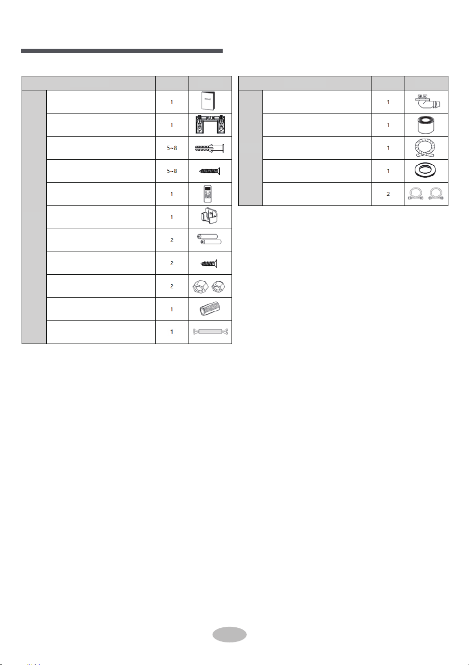
Acessórios
15
Placa de montagem
Parafuso de fixação da
placa de montagem
Interior
Suporte do controlador remoto
Tubo (opcional)
Qty (pc)
Exterior
Parafuso de fixação para suporte
do controlador remoto
Isolador
Mangueira de Drenagem
(opcional)
Acessórios Forma
Manual do Utilizador
Bateria
Fita Vinyl (opcional)
NUT (PORCA)
Acessórios
Forma
Tampa de instalação (opcional)
Cabo de montagem (opcional)
Qty (pc)
Controlador remoto
Âncora
Junta de drenagem (para modelos
de refrigeração e aquecimento)

2.
3.
Fix the wall-mounting frame on the wall with
tapping screws and then check if the frame
is firmly installed by pulling the frame. If the
plastic expansion particle is loose, please
drill another fixing hole nearby.
1.
Hang the wall-mounting frame on the wall; adjust
it in horizontal position with the level meter and
then point out the screw fixing holes on the wall.
Drill the screw fixing holes on the wall with im-
pact drill(the specification of drill head should
be the same as the plastic expansion particle)
and then fill the plastic expansion particles in
the holes.
2.
3.
1.
wall-mounted frame, shown as below.
Choose the position of piping hole according
When installation is finished, pull the mounting
plate with hand to confirm whether it is fixed
tightly. The force distribution for all screws
should be uniform.
Open a piping hole with the diameter of 55
or 0 on the selected outlet pipe position.
In order to drain smoothly, slan t the piping
hole on the wall slightly downward to the
o
utdoor side with the gradient of 5-10°.
to the direction of outlet pipe. The position of
piping hole should be a little lower than the
Pay attention to dust prevention
and take rele vant safety mea-
sures when opening the hole.
2.
2.
3.
1. Aim the pipe joint at the corresponding
rear right, left or rear left.
bellmouth.
Pretighten the union nut with hand.
1. The pipe can be led out in the direction of right,
Adjust the torque force
by referring to the
wrench on the union nut. Tighten the union
nut with torque wrench.
When select leading out the pipe from left or
right, please cut off the corresponding hole on
the bottom case.
following sheet. Place the open-end wren-
ch on the pipe join t and place the torque
ExteriorInterior
5-10
Esquerda traseira
Corte o
buraco
Porca do sindicato
Junta de tubos
Tubo
NOTA
Instale estrutura de montagem na parede
Passo 2:
Tubo de saída
Escolha o local de instalação
Passo 1:
Recomende o local de instalação ao cliente e depois
confirme-o com o cliente.
Direita
Passo 4:
Passo 3:
Abertura do orifício da tubagem
Passo 5:
Ligue o tubo da unidade interior
Instalação de unidade interior
NOTA
Esquerda
Direita
Esquerda
Consulte por favor as circunstâncias reais para o
número de parafusos e a posição dos parafusos.
Direita traseira
O painel de parede é apenas para fins ilustrativos,
consulte por favor a instalação propriamente dita.
Porca do sindicato
Chave de torque
Tubo
Tubo interior
Chave de
boca aberta
Parede
Parede
(Furo de tubagem traseiro)
(Para alguns modelos)
(Furo de tubagem traseiro)
Espaço para a
parede acima
de 150mm
Esquerda
Espaço para a
parede acima
de 150mm
Direita
Marca no meio
Medidor de nível
16
1. Aponte a junta do tubo à embocadura correspondente.
2. Aperte à mão a porca de união.
3. Ajuste a força de aperto consultando a tabela seguinte.
Coloque a chave de bocas na junta do tubo e coloque a
chave dinamométrica na porca de união. Aperte a
porca de união com a chave dinamométrica.
2. Quando selecionar o encaminhamento do tubo para
a esquerda ou direita, corte o orifício correspondente
na caixa inferior.
• Tenha atenção à prevenção de poeiras e
tome medidas de segurança relevantes
quando abrir o orifício.
1. O tubo pode ser encaminhado para a direita, para a
traseira direita, para a esquerda ou para a traseira
esquerda.
2. Quando a instalação estiver concluída, puxe a placa
de montagem com a mão para confirmar se está bem
fixada. A distribuição da força para todos os
parafusos deve ser uniforme.
3. Abra um orifício para o tubo com um diâmetro de Φ
55 ou Φ70 na posição do tubo de saída selecionada.
Para a drenagem ocorrer sem percalços, incline
ligeiramente o orifício para o tubo na parede para
baixo para o lado exterior com um gradiente de
5-10°.
1. Escolha a posição do orifício para o tubo de acordo
com a direção do tubo de saída. A posição do orifício
para o tubo deve ser ligeiramente mais baixa que o
suporte instalado na parede, como demonstrado abaixo.
1. Pendure o suporte de instalação na parede; ajuste-o na
posição horizontal com o medidor de nível e, em
seguida, aponte os orifícios para os parafusos de
fixação na parede.
2. Perfure os orifícios para os parafusos de fixação na
parede com a perfuradora de impacto (a especificação
da cabeça de perfuração deve ser igual à partícula de
expansão de plástico) e, em seguida, coloque as
partículas de expansão de plástico nos orifícios.
3. Fixe o suporte de instalação na parede na parede com
os parafusos de rosca e, em seguida, verifique se o
suporte está firmemente instalado puxando-o para si.
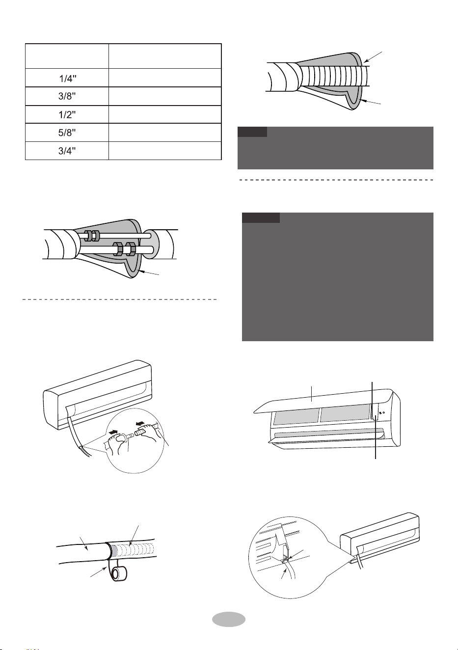
4.
1.
2
.
1.
indoor unit.
Wrap the indoor pipe and joint of connection
pipe with insulating pipe, and then wrap it
with tape.
Open the panel, remove the screw on the wiring
cover and then take down the cover.
Connect the drain hose to the outlet pipe of
Make the power connection wire go through the
cable-cross hole at the back of indoor unit and
then pull it out from the front side.
●
As buchas de expansão não são fornecidas.
●
Todos os fios da unidade de interior e da unidade de
exterior devem ser ligados por um profissional.
●
Se o comprimento do cabo de alimentação for
insuficiente, contacte o fornecedor para obter um novo.
Evite aumentar o cabo por si mesmo.
Adicione tubo de isolamento ao tubo de drenagem de
interior para evitar a condensação.
●
Para o ar condicionado com ficha, esta deve estar
alcançável após a instalação estar concluída.
●
Painel
Mangueira de drenagem
2.
Tubo de saída
Fita
NOTA
●
AVISO
Passo 7:
Ligar o fio da unidade interior
Para o ar condicionado sem ficha, deve ser instalado
um interruptor de pressão na linha. O interruptor de
pressão deve ser de separação geral e a distância de
separação deve ser superior a 3 mm.
Parafuso
Tampa de cablagem
Buraco de
passagem de cabos
Fio de ligação de
energia
Passo 6:
Instalar o tubo de drenagem
Ligar a junta com fita adesiva.
Tubo isolante
Tubo isolante
Mangueira de drenagem
Tubo de
saída
Mangueira de
drenagem
Diâmetro da porca
sextavada
15~20
30~40
45~55
60~65
70~75
17
Torque de aperto (N.m)
2. Passe o cabo de ligação elétrica através do orifício de
cruzamento de cabos na parte de trás da unidade de
interior e, em seguida, puxe-o a partir do lado frontal.
4. Enrole o tubo de interior e a junta do tubo de ligação
com tubo de isolamento e, em seguida, enrole-o com
fita.
1. Ligue o tubo de drenagem ao tubo de saída da unidade
de interior.
1. Abra o painel, remova o parafuso na cobertura dos
cabos e, em seguida, retire a cobertura.

3.
4.
5.
Remove the wire clip; connect the power conn-
ection wire to the wiring terminal according to
the color; tighten the screw and then fix the po-
wer connection wire with wire clip.
Put wiring cover back and then tighten the screw.
Close the panel.
1.
5.
Gancho superior
Unidade
interior
Banda
AVISO
Gancho inferior da armação
de montagem na parede
O cabo elétrico e o fio de controlo não podem ser cruzados
ou enrolados.
O tubo de drenagem deve estar ligado ao fundo.
2.
Interior
3.
Tubo de parede
4.
4.
AVISO
Exterior
Passo 9:
Pendure a unidade interior
2.
Goma de selagem
Tubo
de gás
3.
Tubo líquido
Passo 8:
Ligar tubo
Mangueira de drenagem
1.
Cabo de alimentação
interior e exterior
AVISO
A placa de fiação é apenas para referência, por favor
consulte a real.
Não dobre excessivamente o tubo de drenagem para
evitar bloqueios.
Tubo de ligação
Mangueira de drenagem
Banda
Cabo de alimentação interior
Coloque os tubos ligados no tubo de parede e, em
seguida, passe-os pelo orifício da parede.
Ligue o tubo de drenagem, o cabo elétrico e o
tubo de drenagem com a abraçadeira.
Atá-los uniformemente.
O tubo de líquido e o tubo de gás devem ser
ligados separadamente nas extremidades.
Pendure a unidade de interior no suporte de
instalação na parede.
Preencha o espaço entre os tubos e o orifício
na parede com látex de isolamento
Fixe o tubo de parede.
Verifique se a unidade de interior está firmemente
instalada e junto à parede.
Ligação de unidade ao exterior
N(1) 2 3
Amarelo -
verde
Castanho
PretoAzul
Reserve algum comprimento do tubo de drenagem
e do cabo elétrico para a instalação quando os
estiver a ligar. Quando ligados até um certo ângulo,
separe o cabo elétrico de exterior e, em seguida,
separe o tubo de drenagem.
18
4. Volte a colocar a cobertura dos cabos e aperte o
parafuso.
5. Feche o painel.
3. Remova o terminal; ligue o cabo de ligação elétrica
com o terminal de ligação de acordo com a cor; aperte o
parafuso e fixe o cabo de ligação elétrica com o
terminal.

2.
1.
2.
1. Connect the outdoor drain joint into the hole
Select installation location according to
the house structure.
Fix the support of outdoor unit on the sele-
cted location with expansion screws.
on the chassis, as shown in the picture below.
Connect the drain hose into the drain vent.
As for the shape of drainage joint, please refer
to the current product. Do not install the drainage
joint in the severe cold area. Otherwise,it will be
frosted and then cause malfunction.
When there're multiple cables
passing through it, the cross-ho
le
of handle should be knocked off
and eliminate the sharp burrs for
avoid damaging the cables.
Only applicable for some models.
Take sufficient protective measures when installin g
the outdoor unit.
Make sure the support can withstand at least fou r
times of the unit weight.
The outdoor unit should be installed at least
3cm above the floor in order to install drain joint.
(for the model with heating tube, the installation
height should be no less than 20cm.)
For the unit with cooling capacity of 2300W
~
5000W,
6 expansion screws are needed ; for
the unit with cooling capacity of 6000W~8000W,
8 expansion screws are needed; for the unit
with cooling capacity
of 10000W~16000W, 10
expansion screws are needed.
2. Fixe os orifícios inferiores da unidade de exterior
com cavilhas.
Furos para os pés
Furos para os pés
1. Remova o parafuso na pega direita da unidade de
exterior e, em seguida, remova a pega.
(Selecioná-lo de acordo com a situação real
de instalação)
Passo 1:
Fixe o suporte da unidade exterior
Válvula de gás
Tubo líquido
Tubo de gás
Válvula
de
líquido
Passo 4:
Ligar tubos interiores e exteriores
Porca do sindicato
Junta de tubos
Passo 3:
Fixar unidade exterior
AVISO
Instalação da unidade exterior
Passo 2:
Instalar junta de drenagem
(Apenas para alguns modelos)
AVISO
NOTA
Buraco cruzado
2. Remova a proteção do parafuso da válvula e
aponte a junta do tubo à embocadura do tubo.
3.
PretighteAperte à mão a porca de união.
Manípulo
Parafuso
Abertura de drenagem
Mangueira de drenagem
Chassi
Junta de drenagem exterior
Pelo menos 3cm acima do chão
19
1. Coloque a unidade de exterior no suporte.
• Quando houver cabos múltiplos a passar
por ela, o furo transversal do cabo deve
ser cortado e eliminar as rebarbas afiadas
para evitar danificar os cabos.
• Apenas aplicável para alguns modelos.
• No que respeita a forma da junta de drenagem
consulte o produto atual. Não instale a junta de
drenagem numa área de frio severo. Caso
contrário, ficará congelada e causar avarias.
● Tome medidas de proteção suficientes ao instalar a
unidade exterior.
● Certifique-se de que o suporte consegue suportar, pelo
menos, quatro vezes o peso da unidade.
● A unidade de exterior deve ser instalada a, pelo menos, 3
cm do chão para que possa ser instalada a junta de
drenagem. (Para o modelo com o tubo de aquecimento, a
altura de instalação deve ser superior a 20 cm.)
● Para a unidade com a capacidade de arrefecimento de
2300 W a 5000 W, são necessários 6 parafusos de
expansão; para a unidade com a capacidade de
arrefecimento de 6000 W a 8000 W, são necessários 8
parafusos de expansão; para a unidade com a capacidade
de arrefecimento de 10000 W a 16000 W, são necessários
10 parafusos de expansão.
1. Selecione o local de instalação de acordo com a
estrutura da habitação.
2. Fixe o suporte da unidade de exterior no local
selecionado com parafusos de expansão.
1. Ligue a junta de drenagem de exterior ao orifício no
chassi, como demonstrado na imagem abaixo.
2. Ligue o tubo de drenagem à ventilação de drenagem.

4.
2.
1.
Tighten the union nu t with torque wrench
by referring to the sheet below.
The pipes should be placed along the wall, bent
If the outdoor unit is higher than the wall hole,
reasonably and hidden possibly. Min. semidiam-
eter of bending the pipe is 10cm.
you must set a U-shaped curve in the pipe
before pipe goes into the room, in order to
prevent rain from getting into the room.
1. Remova o terminal; ligue o cabo de ligação elétrica e o
fio de controlo de sinal (apenas nas unidades de
arrefecimento e de aquecimento) ao terminal de ligação
de acordo com a cor; fixe-os com parafusos.
Diâmetro da porca sextavada
Torque de aperto (N m)
.
Parede
A mangueira de drenagem não pode ser flutuante
A saída de água não pode ser colocada dentro de
água para que saia sem problemas.
2.
1/4''
3/8''
1/2''
5/8''
3/4''
15~20
30~40
45~55
60~65
70~75
Ligar o fio elétrico exterior
Passo 5:
A mangueira de drenagem
não se pode levantar para
cima.
A saída de água
não pode ser
colocada na água
Incline ligeiramente para baixo o tubo de
drenagem. O tubo de drenagem não deve estar
curvado, elevado e flutuante, etc.
A mangueira de
drenagem não pode
ser flutuante
A saída de água
não pode estar
flutuante
Fixe o cabo de ligação elétrica e o fio de controlo do
sinal com o terminal (apenas para as unidades de
arrefecimento e aquecimento).
Passo 6:
Organizar os tubos
Curva em U
Mangueira de drenagem
AVISO
AVISO
AVISO
A placa de fiação é apenas para referência, por favor
consulte a real.
Depois de apertar o parafuso, puxar ligeiramente o cabo
de alimentação para verificar se está firme.
Nunca corte o cabo de ligação elétrica para aumentar ou
encurtar a distância.
A altura da mangueira de drenagem através da
parede não deve ser superior ao orifício do tubo
de saída da unidade interna.
Ligação de unidade interior
N(1) 2 3
Azul
Preto
Castanho
Amarelo
- verde
20
4. Aperte a porca de união com a chave dinamométrica
consultando a tabela abaixo.
1. Os tubos devem ser colocados ao longo da parede,
razoavelmente curvados e, se possível, ocultados. O
semidiâmetro mínimo de curvatura do tubo é de 10 cm.
2. Se a unidade de exterior estiver mais alta que o orifício
da parede, deve definir uma curva em U antes de o tubo
entrar na área, para evitar que entre chuva na divisão.

serp ,rewop eht hguorht tuP
s " ON/OFF " button on
the remote controller to start operation.
Press MODE button to select AUTO, COOL, DRY ,
FAN and HEAT to check whether the operation s i
normal or not.
If the ambient temperature is lower than 16℃ e ht ,
air conditioner can’t start cooling.
●
●
●
Operação de teste
Teste e operação
1.
●
●
Preparação da operação de teste
O cliente aprova o aparelho de ar condicionado.
Especifique ao cliente as notas importantes do ar condicionado.
6.
Detecção de fugas
Usar bomba de vácuo
Aperte as proteções das válvulas e da abertura de carregamento
do líquido refrigerante.
1.
2.
5.
4.
1.
Reinstale o punho.7.
Remova o piezómetro, abra o núcleo da válvula da
válvula do líquido e da válvula de gás completamente
com a chave hexagonal interna.
piezometer
Tampa da válvula
Válvula de líquido
Lo Hi
Válvula de gás
Ventilação da carga
do refrigerante
A porca da abertura
de carregamento do
líquido refrigerante.
Fechar
Abrir
Bomba de vácuo
Chave hexagonal
interior
Feche a bomba de vácuo e mantenha esse estado durante
1-2 minutos para verificar se a pressão do piezómetro
permanece em -0,1 MPa. Se a pressão diminuir, pode
haver fugas.
21
2.
3.
Abra o piezómetro completamente e coloque em
funcionamento durante 10-15 minutos para verificar se a
pressão do piezómetro permanece em -0,1 MPa.
Remova as proteções das válvulas na válvula do líquido e
na válvula de gás e a porca da abertura de carregamento do
líquido refrigerante.
Com detector de fugas:
Com água com sabão:
Se não tiver um detetor de fugas, utilize água e sabão
para a deteção de fugas. Aplique água com sabão onde
suspeita haver uma fuga e mantenha a água com sabão
no local durante mais de 3 minutos. Se existirem bolhas
neste local, existe uma fuga.
Verificação após a instalação
●
Verifique de acordo com o seguinte requisito após a
conclusão da instalação.
Possível mau funcionamento
A unidade poderá cair, abanar ou
produzir ruídos.
A água está a ser bem drenada?
Pode causar condensação e
gotejamento de água.
Itens a serem verificados
A unidade foi instalada
com firmeza?
Efetuou o teste de fugas de
líquido refrigerante?
Pode causar mau funcionamento ou
danificar as peças.
A fiação elétrica e as tubagens
estão instaladas corretamente?
Pode causar mau funcionamento ou
danificar as peças.
A unidade está aterrada em
segurança?
O cabo de alimentação segue a
especificação?
Pode causar mau funcionamento ou
danificar as peças.
Existem obstruções na entrada de
ar e na saída de ar?
Pode causar mau funcionamento ou
danificar as peças.
A válvula de gás e a válvula do
líquido do tubo de ligação estão
completamente abertas?
A poeira e os detritos causados
durante a instalação foram
removidos?
O isolamento térmico das
tubagens é suficiente?
A entrada e a saída do orifício do
tubo foram cobertas?
A tensão da alimentação está
consoante a tensão marcada na
placa?
Poderá causar uma capacidade de
arrefecimento (aquecimento)
insuficiente ou desperdiçar energia
elétrica.
Método de operação de teste2.
Ligue o tubo de carregamento do piezómetro à abertura
de carregamento do líquido refrigerante da válvula de gás
e, em seguida, ligue o outro tubo de carregamento à
bomba de vácuo.
Verifique se existem fugas com o detetor de fugas.
Pode causar uma capacidade de
refrigeração (aquecimento) insuficiente.
Pode causar condensação e
gotejamento de água.
Pode causar fugas elétricas.
Pode causar uma capacidade de
refrigeração (aquecimento)
insuficiente.
Pode causar uma capacidade de
refrigeração (aquecimento)
insuficiente.
● Ligue a fonte de alimentação e, de seguida, prima o
botão ON/OFF no comando para iniciar a operação.
● Prima o botão MODE para selecionar AUTO, COOL,
DRY, FAN e HEAT para verificar se o funcionamento
está normal ou não.
● Se a temperatura ambiente estiver abaixo de 16 °C, o
ar condicionado não pode iniciar o arrefecimento.

1.
2.
3.
Standard length of connection pipe: 5m, 7.5m,
4.
The additional refrigerant oil and refrigerant charg-
ing required after prolonging connection pipe.
8m.
Min. length of connection pipe is 3m.
Max. length of connection pipe is shown as below.
After the length of connection pipe is prolonged
for 10m at the basis of standard length, you should
add 5ml of refrigerant oil for each additional 5m
of connection pipe.
The calculation method of additional refrigerant
charging amount(on the basis of liquid pipe):
Additional refrigerant charging amount =
prolonged length of liquid pipe × additional
refrigerant charging amount per meter
Basing on the length of standard pipe, add re-
frigerant according to the requirement as shown
in the table. The additional refrigerant charging
amount per meter is different according to the
diameter of liquid pipe. See the following sheet.
Improper pipe expanding is the main cause of refriger-
ant leakage. Please expand the pipe according to the
following steps:
●
●
●
22
15
15
15
20
25
Comprimento
máximo do tubo de
ligação (m)
25
30
30
30
30
Comprimento máximo do tubo de ligação
Método de expansão de tubos
Capacidade de refrigeração
5000Btu/h (1465W)
7000Btu/h (2051W)
9000Btu/h (2637W)
12000Btu/h (3516W)
18000Btu/h (5274W)
24000Btu/h (7032W)
28000Btu/h (8204W)
36000Btu/h (10548W)
42000Btu/h (12306W)
48000Btu/h (14064W)
Cortador de tubos
Tubo
●
A: Cortar o tubo
●
Inclinado burrÍmpar
Configuração da tubagem de ligação
Confirme o comprimento do tubo de acordo com a
distância da unidade interior e da unidade exterior.
Corte o tubo necessário com cortador de tubos.
15
Montante adicional de carregamento de refrigerante para
R22, R407C, R410A e R134a
20
15
50
30
AVISO
120
60
120
250 250
350 350
Tubo de gás
3/8'' ou 1/2''.
5/8'' ou 3/4''.
3/4'' ou 7/8''.
1'' ou 1 1/4''
_
_
Tamanho da tubagem
Tubo líquido
1/4''
Acelerador da unidade exterior
Apenas arrefecimento
(g/m)
Arrefecimento e
aquecimento (g/m)
1/4'' ou 3/8''
1/2''
5/8''
3/4''
7/8''
• O método de cálculo da quantidade de líquido
refrigerante adicional (com base no tubo de
líquido): Quantidade de líquido refrigerante
adicional = comprimento do tubo de líquido
prolongado * quantidade do carregamento de
líquido refrigerante por metro
• Depois do comprimento do tubo de ligação ser
aumentado 10 m com base no comprimento padrão,
deve adicionar 5 ml de óleo refrigerante por cada 5
m de tubo de ligação.
• Com base no comprimento do tubo padrão,
adicione líquido refrigerante de acordo com os
requisitos apresentados no quadro. A quantidade de
carregamento de líquido refrigerante por metro é
diferente de acordo com o diâmetro do tubo de
líquido. Consulte a tabela seguinte.
4. Óleo refrigerante adicional e carregamento de
líquido de refrigeração necessários após prolongar o
tubo de ligação
O aumento inadequado do tubo é a causa principal de
fugas de líquido refrigerante. Aumente o tubo de
acordo com os seguintes passos:
1. Comprimento padrão do tubo de ligação: 5 m, 7,5
m, 8 m.
2. O comprimento mínimo do tubo de ligação é 3 m.
3. O comprimento máximo do tubo de ligação é
mostrado como abaixo.
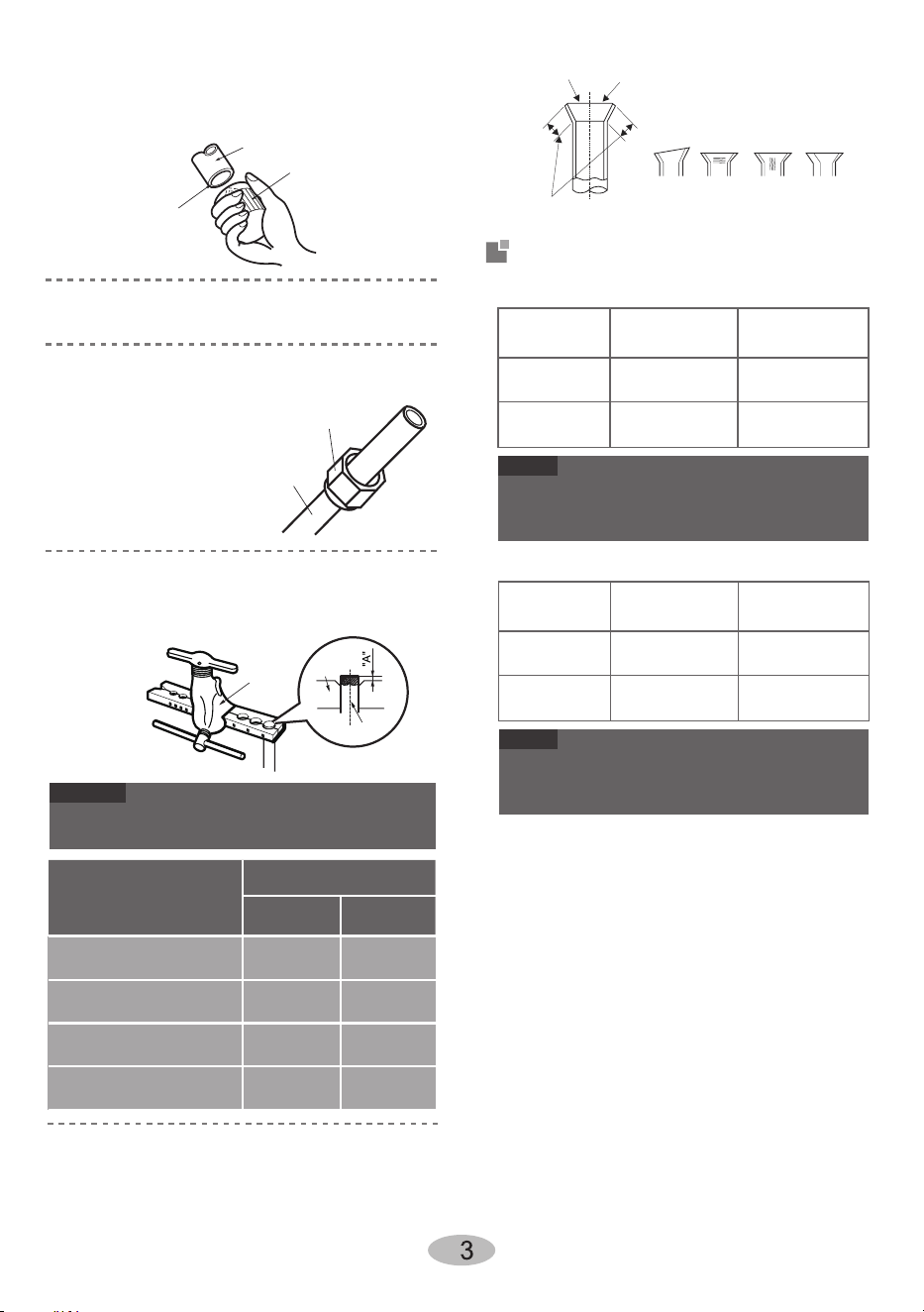
Check the quality of expanding port. If there is
●
any blemish, expand the port again according to
the steps above.
The operating temperature range (outdoor tem -
●
perature) for cooling onl y
unit is 18
°C
~48
°C
;for
heat pump unit is -7
°C
~48
°C
.
The operating temperature range (outdoor tem -
●
perature) for cooling onl y
unit is 18
°C
~43
°C
;for
heat pump unit is -7
°C
~43
°C
.
Remova as rebarbas com o formatador e evite que
entrem rebarbas no tubo.
O comprimento é igual
Gama de temperaturas de trabalho
Tubo de união
Tubo
2
C: Colocar em tubo isolante adequado
Superfície lisa
Expansão imprópria
Espessura
desigual
Inclinado
Superfície
danificada
Rachadura
Expansor
Tubo
Molde
duro
AVISO
●
●
B: Remover as rebarbas
D: Colocar a porca da união
●
●
E: Expandir o porto
F: Inspeção
Modelador
Para baixo
Tubo
A(mm)
Max
Min
Φ6 - 6.35(1/4")
1.3 0.7
1.6 1.0Φ9 - 9.52(3/8")
Φ12-12.7(1/2")
1.8 1.0
Φ15.8-16(5/8")
2.4 2.2
Diâmetro exterior
(mm)
32/23 48/26
27/- 24/18
Lado interior
DB/WB (°C)
Lado exterior
DB/WB (°C)
Lado interior
DB/WB (°C)
Lado exterior
DB/WB (°C)
Arrefecimento
máximo
Aquecimento
máximo
NOTA
32/23 43/26
27/- 24/18
Arrefecimento
máximo
Aquecimento
máximo
NOTA
09K.12K.18K.24K SA inversor :
09K.12K.18K.24K AF inversor :
Remova a porca de união na válvula do tubo de ligação
de interior e de exterior; instale
a porca de união no tubo.
Alargue a porta com o expansor
"A" é diferente de acordo com o diâmetro, consulte a
tabela abaixo:
O intervalo de temperatura em funcionamento (temperatura
exterior) para a unidade de arrefecimento apenas é entre 18 °C e
43 °C; para a unidade de bomba de aquecimento é entre -7 °C e
43 °C.
Verifique a qualidade da porta alargada. Caso
existam manchas, volte a alargar a porta de acordo
com os passos acima.
O intervalo de temperatura em funcionamento (temperatura
exterior) para a unidade de arrefecimento apenas é entre 18°C
e 48 °C; para a unidade de bomba de aquecimento é entre -7
°C e 48 °C.

CONTRIBUIÇÃO CHAMADA OU VISITE-NOS ONLINE EM
ÁFRICA DO SUL 0860 SAMSUNG (726 7864) www.samsung.com/za/support
NAMIBIA 08 197 267 864
www.samsung.com/africa_en/support
ZAMBIA
3434
MAURITIUS
800 5050
NIGERIA 0800 726 7864
GHANA 0800 100 077
KENYA 0800 545 545
UGANDA 0800 300 300
TANZANIA 0800 780 089
REUNIÃO 0262 50 88 80
www.samsung.com/africa_fr/support
Cote D’Ivoire 8000 0077
SENEGAL 800 00 0077
CAMARÕES 67095 0077
MOZAMBIQUE 84 726 7864 www.samsung.com/africa_pt/support
SUDAN 1969 www.samsung.com/eg/support
PERGUNTAS OU COMENTÁRIOS?
Capa_GREE_ÁFRICA.indd 2 2019-10-25 오후 3:14:38
66139903397