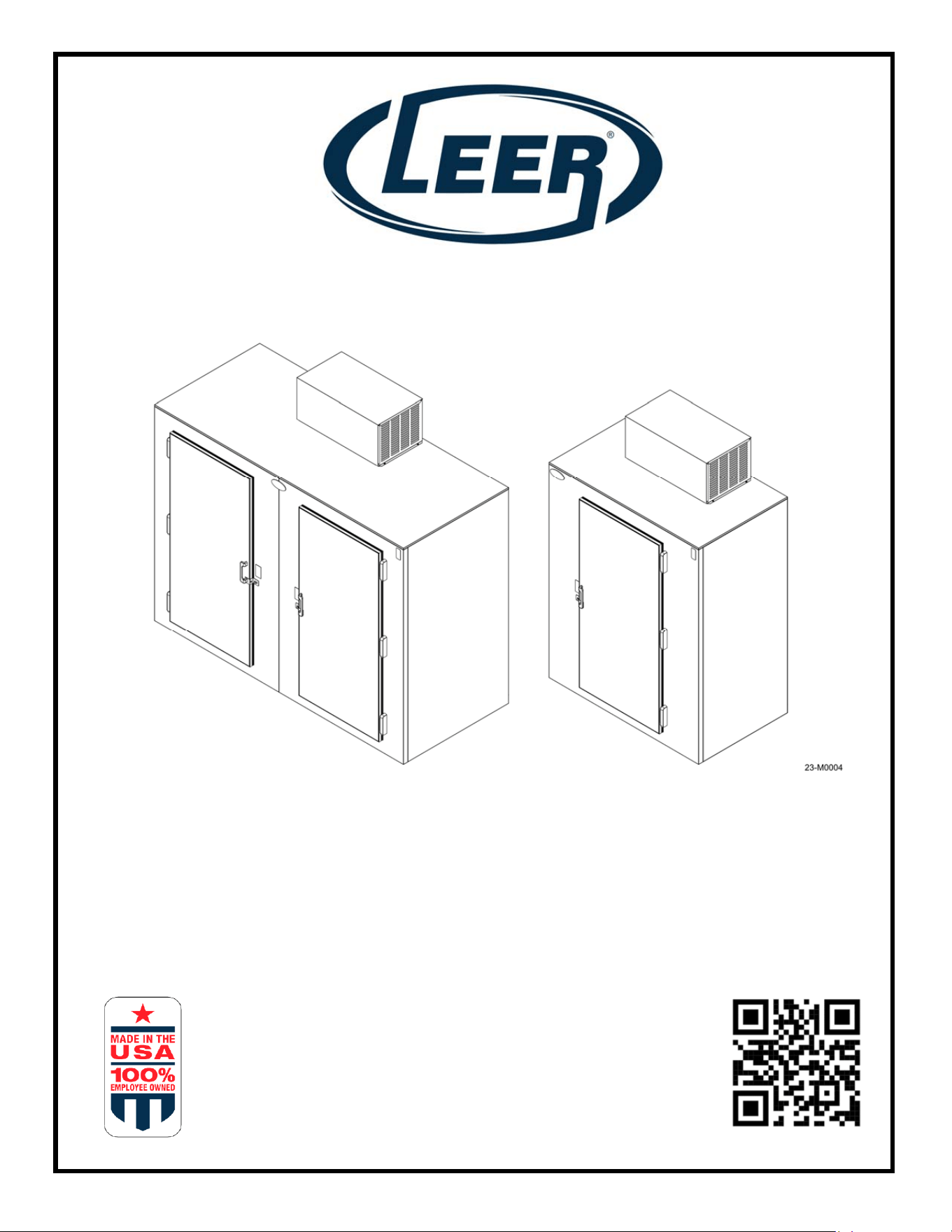
S85 & S40
INSTALLATION, OPERATION AND
SERVICE MANUAL
1070340R2 12-23
2
Leer, Inc.
206 Leer Street
P.O. Box 206
New Lisbon, WI 53950
1-800-766-5337
www.leerinc.com
This manual provides information and procedures to safely operate and maintain your LEER
product. For your own safety and protection from physical injury, carefully read, understand and
observe the safety instructions described in this manual. Keep a copy of this manual with the unit
at all times. Additional copies are available from LEER, Inc. or can be found by scanning the QR
code on the unit or the front cover of this manual. The information contained in this manual was
based on equipment in production at the time of publication. LEER, Inc. reserves the right to
change any portion of this information without notice.
UNIT MODEL NUMBER:____________________________________
UNIT SERIAL NUMBER:____________________________________
Leer, Inc. is 100% Employee-Owned and we believe it’s those employee owners that make a
distinctive difference, to Leer’s dedication to quality and service across all our product lines,
because you have the commitment not just of one owner - but over 225 owners.
Our Mission
To partner with our customers to design and develop the highest quality, innovative,
temperature-controlled storage solutions to meet their ever-changing needs and to
provide our customers exceptional quality and outstanding customer service at every
stage of every interaction.

3
Contents
Section 1 – Safety and General Information ............................................................... 4
1.1 Safety Rules .......................................................................................................... 4
1.2 Safety Symbols ...................................................................................................... 4
Section 2 - Specifications ............................................................................................. 6
2.1 System Specifications ............................................................................................ 6
2.3 Dimensions ............................................................................................................ 7
2.4 Model Component Locations ................................................................................. 9
Section 3 - Transport, Unpacking, & Installation ...................................................... 13
3.1 Transporting the unit ............................................................................................ 13
3.2 Unpacking the unit ............................................................................................... 13
3.3 Installation ........................................................................................................... 14
3.4 Placement ............................................................................................................ 14
3.5 NSF Spacer Kit .................................................................................................... 15
Section 4 – Operation ................................................................................................. 16
4.1 How the System Works ....................................................................................... 16
4.2 Powering Up ........................................................................................................ 17
4.3 Controller Operation ............................................................................................ 17
4.4 Changing the Operating Temperature ................................................................. 18
4.5 Adjusting the Shelving ......................................................................................... 19
4.6 Loading the Unit ................................................................................................... 19
Section 5 - Maintenance ............................................................................................. 21
5.1 General Information ............................................................................................. 21
5.2 Cleaning the Unit ................................................................................................. 22
5.3 Defrosting ............................................................................................................ 23
5.4 Door Hinge Install and Adjustment ...................................................................... 23
5.5 Refrigeration System Maintenance ...................................................................... 25
Section 6 - Troubleshooting ....................................................................................... 29
6.1 Troubleshooting Tables ....................................................................................... 29
Section 7 – Wiring Diagrams ...................................................................................... 32
7.1 Wiring Diagrams. ................................................................................................. 32
Warranty ....................................................................................................................... 33
4
Section 1 – Safety and General Information
1.1 Safety Rules
Study these SAFETY RULES carefully before set-up, operation or service of the unit. Become
familiar with this operating manual and the unit itself. The unit can operate safely, efficiently and
reliably only if it is properly setup, operated and maintained. Many accidents are caused by
failure to follow simple and fundamental rules or precautions.
This manual contains DANGERS, WARNINGS, CAUTIONS and NOTES which must be
followed to prevent the possibility of improper service, damage to the equipment, personal injury
or death.
The following formatting options will apply when calling the reader’s attention to the DANGERS,
WARNINGS, CAUTIONS and NOTES.
DANGER: Indicates a hazardous situation which, if not avoided, will result in death or serious
injury.
WARNING: Indicates a hazardous situation which, if not avoided, could result in death or
serious injury.
CAUTION: Indicates a hazardous situation which, if not avoided, could result in minor or
moderate injury AND could result in property or equipment damage.
NOTE: Notes contain additional information important to a procedure and will be found within
the regular text body of this manual.
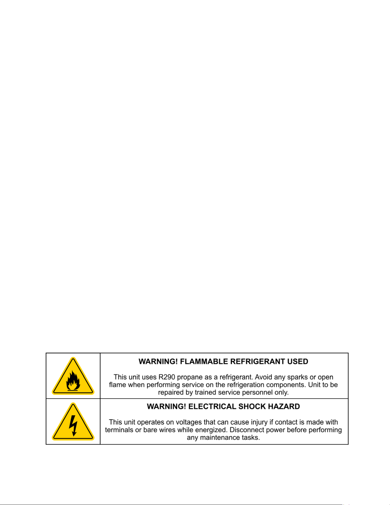
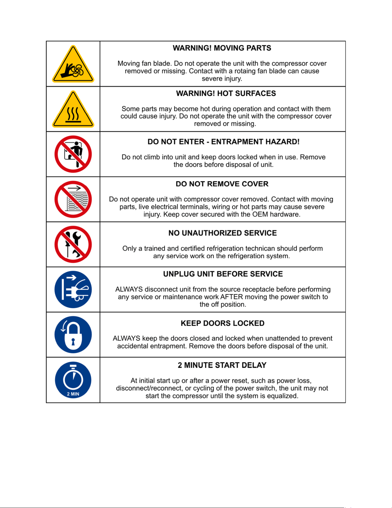
1.2 Safety Symbols
This equipment has been supplied with numerous safety and operating decals. These decals
provide important operating instructions and warn of dangers and hazards. Replace any missing
or hard-to-read decals and use care when washing or cleaning the unit. Decal placement and
part numbers can be obtained by contacting Leer direct at 1-800-766-5337.
All safety decals are available free of charge with a valid model and serial number.
Below is a summary of the intended meanings for the symbols used on the decal. Some or all of
these symbols may be part of your Leer product:
5
6
Section 2 - Specifications
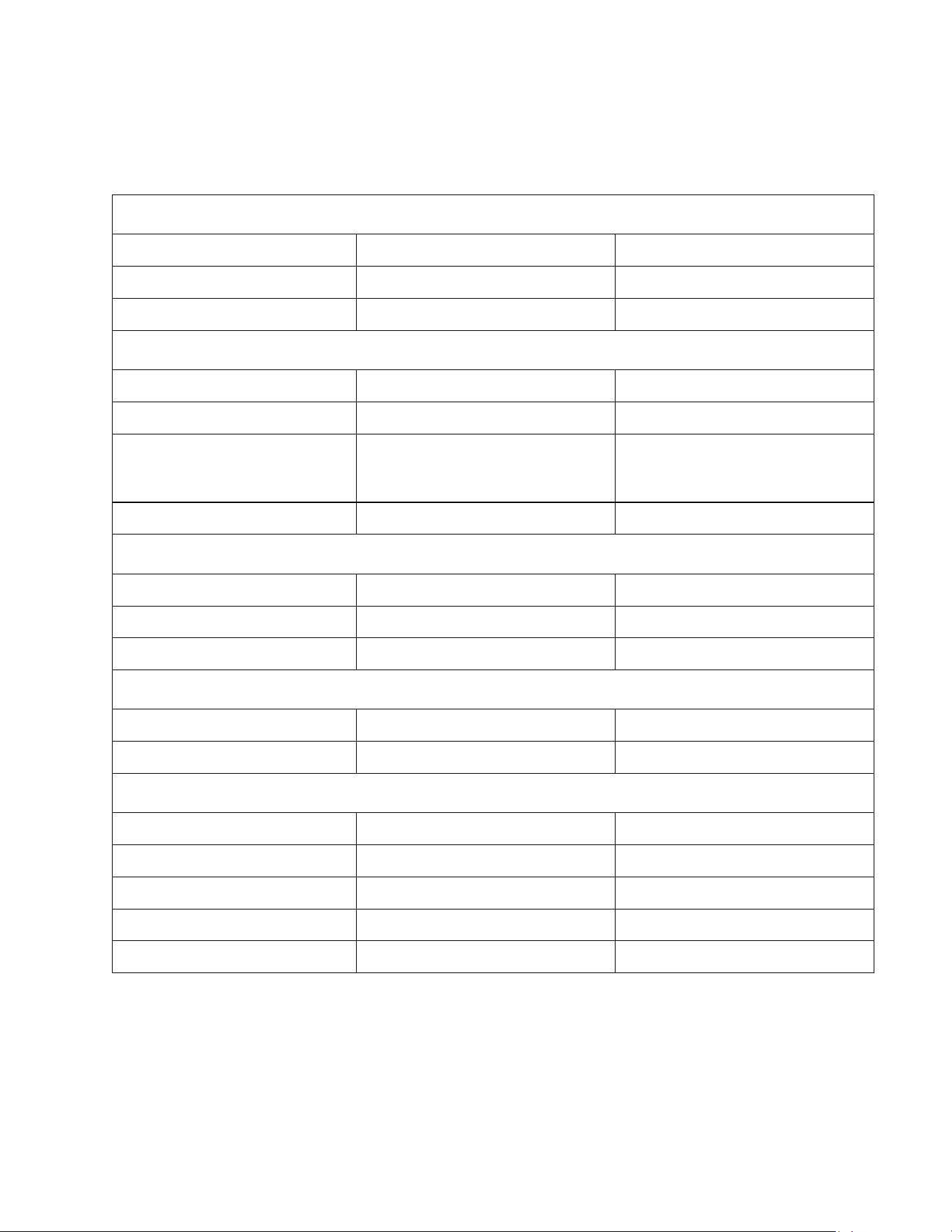
2.1 System Specifications
S40 and S85 Models
MODEL S40 S85
Freezer S040UASPF S085UASPF
Refrigerator S040UASPR S085UASPR
General Specifications
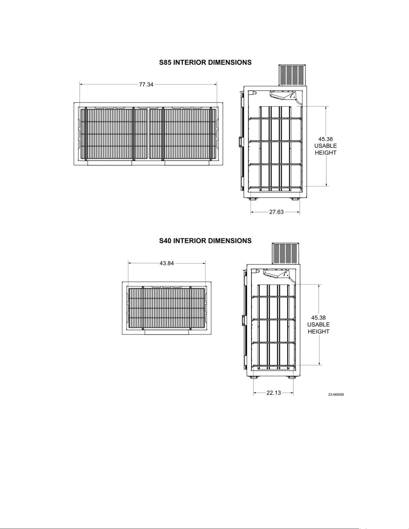
Interior Space - cu/ft (cu/m) 38 (1.08) 80.0 (2.27)
Door Opening - in (cm) 25.4 x 57.7 (64.5 x 146.6) 25.4 x 57.7 (64.5 x 146.6)
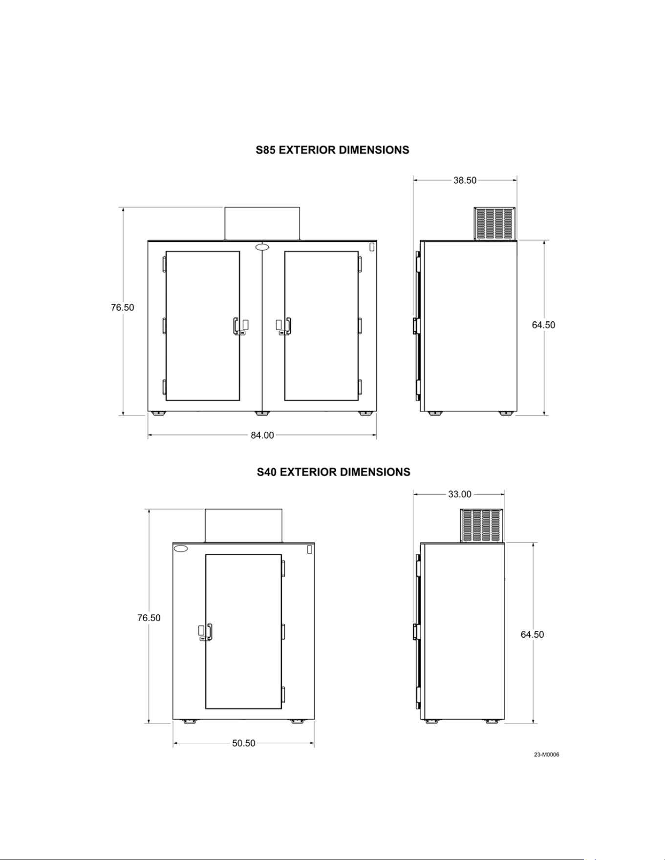
Exterior - in (cm)
33.00 x 50.5 x 76.50
(83.8 x 127.5 x 194.3)
38.50 x 84 x 76.50
(97.8 x 213.4 x 194.3)
Unit Weight - lb (kg) 410 (186.0) 665 (301.6)
Temperature and Controls
Freezer °F (°C) -4 to 0 (-20 to -17.8) -4 to 0 (-20 to -17.8)
Refrigerator °F (°C) +34 to 40 (2.2 to 3.3) +34 to 40 (2.2 to 3.3)
Control Type Electronic Electronic
Electrical Specifications
Voltage (V/Hz) 120/60 120/60
Minimum Circuit (Amps) 15 15
Refrigeration Specifications
Refrigerant
R290 R290
Certifications UL, ULC UL, ULC
DOE Compliant Yes Yes
NRCan Compliant Yes Yes
NSF Certification Yes Yes
7
2.3 Dimensions
Figures 2-1 and 2-2 for the interior and exterior dimensions of the S85 and S40.
Figure 2-1
8
Figure 2-2
9
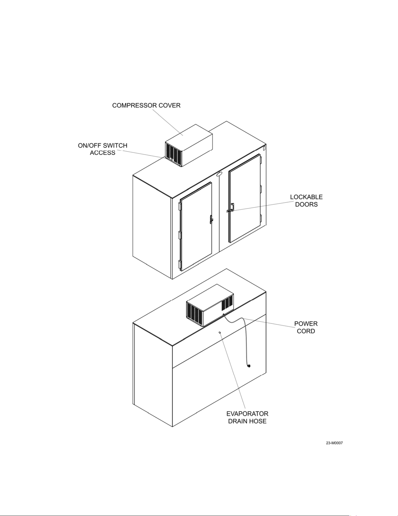
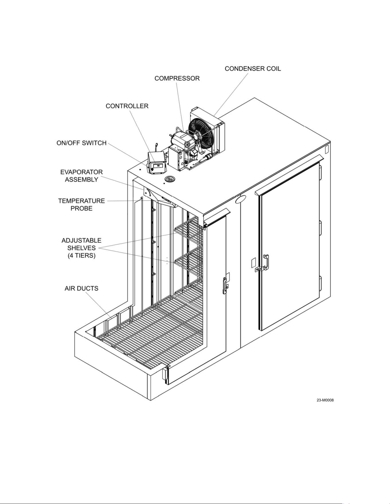
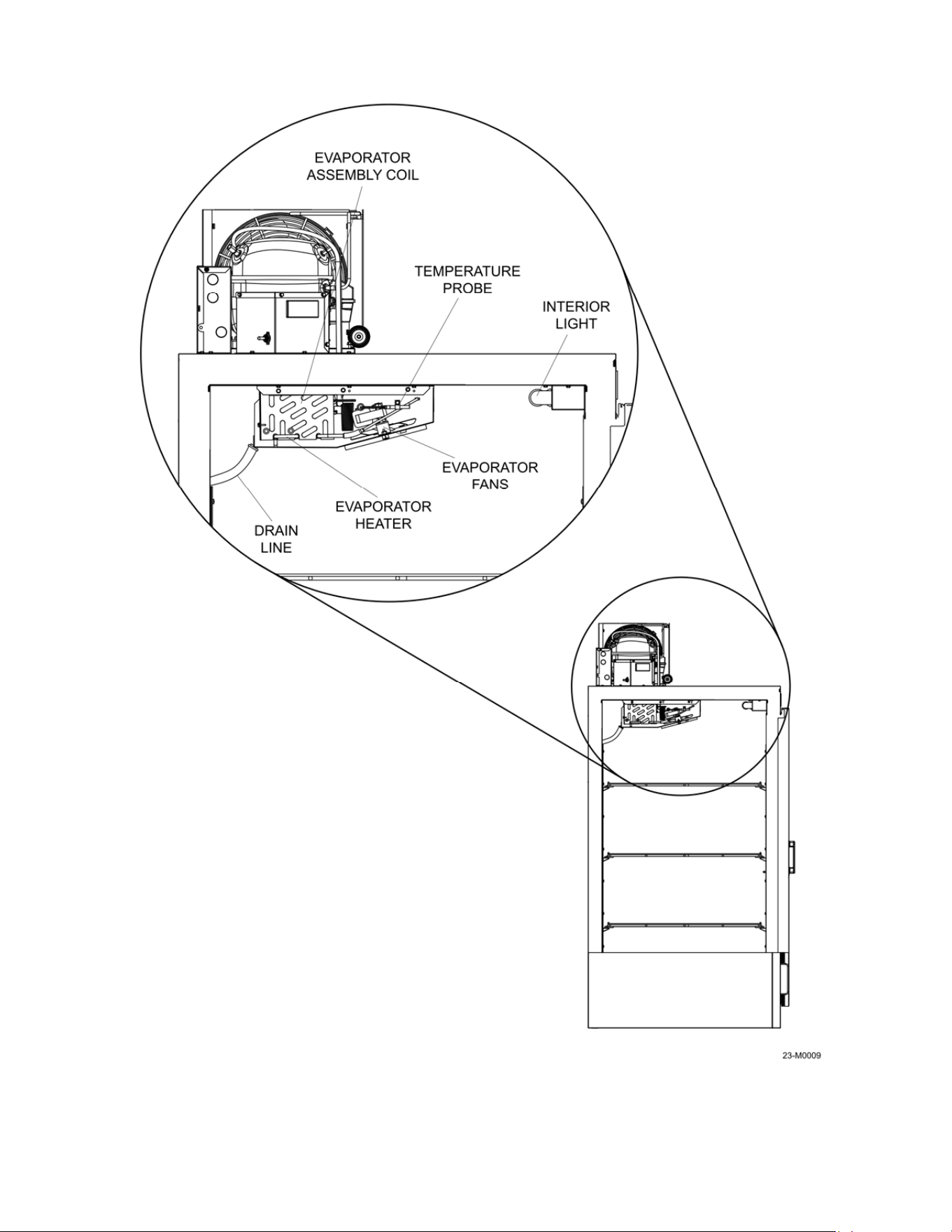
2.4 Model Component Locations
Refer to Figures 2-3 to 2-5 for the location of components.
Figure 2-3
10
Figure 2-4
11
Figure 2-5

12
Compressor Cover: The compressor cover protects the refrigeration components from access
by unauthorized persons. Keep the cover secured to the top of the unit at all times.
ON/OFF Switch Access: The hole in the cover allows the unit to be turned on or off without the
need to remove the cover.
Lockable Doors: The doors on the S40 and S85 can be secured with a padlock if necessary.
Merchandiser Power Cord: The unit is equipped with a 3-prong 15A plug. Always plug the unit
into a dedicated circuit – DO NOT USE EXTENSION CORDS TO POWER THE UNIT.
Evaporator Drain Hose: The drain hose carries meltwater from the evaporator assembly drain
pan to the exterior of the unit.
Condenser Coil: Used to extract heat from the refrigerant when it is a high-pressure, high-
temperature gas to a high-pressure, high temperature liquid, see Section 4.
Compressor: Device that makes low-pressure, low-temperature gas to an outgoing high-
pressure, high-temperature gas, see Section 4.
Air Ducts: Ducting allows for better airflow along the back and side of the unit for better
temperature control.
Controller: Programmable digital controller; used to set operating parameters of the unit.
On/Off Switch: Turns the power on/off for the unit.
Evaporator Assembly: Cools the interior of the unit to the programmed temperature set on the
controller.
Adjustable Shelves: Shelves for loading product – 4 shelves are sent with the S40 and 8
shelves are sent with the S85.
Evaporator Assembly Coil: As the refrigerant passes through the coil, fans push the warmer
air from the interior of the unit across the coil so the heat is absorbed by the lower temperature
liquid in the coil, see Section 4.
Temperature Probe: Detects the temperature inside of the unit for input to the controller.
Interior Light: LED light to illuminate the interior of the unit.
Evaporator Fans: Fans circulate air inside the unit.
Evaporator Heater: Used to defrost the evaporator coil at programmed intervals.
Drain Line: Carries water melted by the evaporator heater to the exterior of the unit.
13
Section 3 - Transport, Unpacking, & Installation
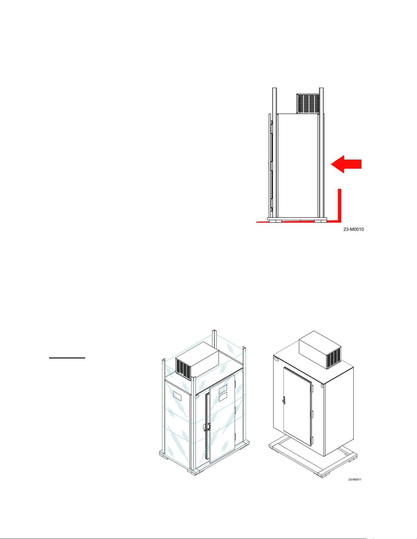
3.1 Transporting the unit
When unloading and moving the Leer box from the truck
to the permanent location:
1. Verify the lifting device has adequate capacity to
move the box, see the specifications in Section 2
for the unit’s size and weight.
2. Make sure the fork tines of the forklift are long
enough and positioned wide enough to provide
adequate support of the shipment, refer to
Figure 3-1.
NOTE: DO NOT tip the unit when transporting! If
the unit is moved at an angle (45 degrees or
more) oil from the compressor may leak into the
refrigerant tubing path and cause premature
failure of the refrigeration system.
3. A thorough inspection of the unit must take place
to make sure that no damage has occurred
during the shipping process.
3.2 Unpacking the unit
NOTE: Thoroughly inspect this unit before and after uncrating for possible damage that
may have occurred during the shipping process. If damage is apparent, note damage on
the delivery receipt
before the driver leaves.
Damage claims not
noted on the delivery
WILL NOT be assessed.
Remove the outer
wrapping and any crating
from the sides of the
shipment first, then
remove the shipping base
from the bottom, refer to
Figure 3-2. The base is
held on with hex-head
screws that will require a
3/8” socket or wrench to
remove. Optional items
may be included in
separate boxes that are
shipped inside the unit.
Figure 3-1
Figure 3-2
14
Be sure to remove and inventory these items as well as check for possible shipping damage
to the optional items and the inside of the unit.
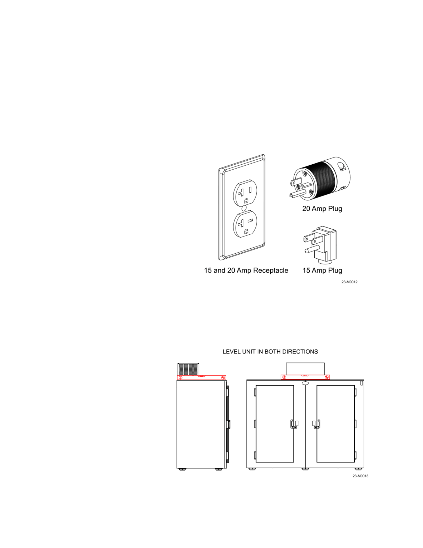
3.3 Installation
Electrical connections: Electrical service connections must be in accordance with the National
Electrical Code, as well as any state or local codes that may apply. The electrical voltage and
frequency must coincide with the serial tag. All units are equipped with a 3-prong NEMA 5-15P
or 20P plug, refer to Figure 3-3.
WARNING!
Improper use or removal of the grounding plug can result in a risk of electrical shock.
The refrigeration system must be
connected to a dedicated 120-volt, 60
Hz grounded electrical outlet with a
circuit breaker or fuse. The condensing
unit data plate will indicate the
maximum circuit breaker size required.
NOTE: DO NOT
use standard
extension cords! Extension cords
will decrease the voltage to the
refrigeration unit and ultimately
cause the compressor to fail
prematurely.
3.4 Placement
Avoid placing the unit in direct sunlight or next to dark colored surfaces, if possible, to reduce
the amount solar heat the unit may be exposed to. Do not place the unit under or near
downspouts, low areas or roof overhangs that may be subject to high water flows.
Allow for an air gap of 3”
behind the unit to allow for air
circulation around the box –
this will aid in the operation of
the refrigeration system.
Place the unit on a firm, level
surface. If the unit is leaning to
the front, the doors may not
seal properly and the drain
tube on the evaporator
assembly may not empty
completely, leading to ice
buildup. Place a level on the
top of the unit and shim/adjust
the feet until the unit is level in
both directions, refer to Figure
3-4.
Figure 3-3
Figure 3-4
15
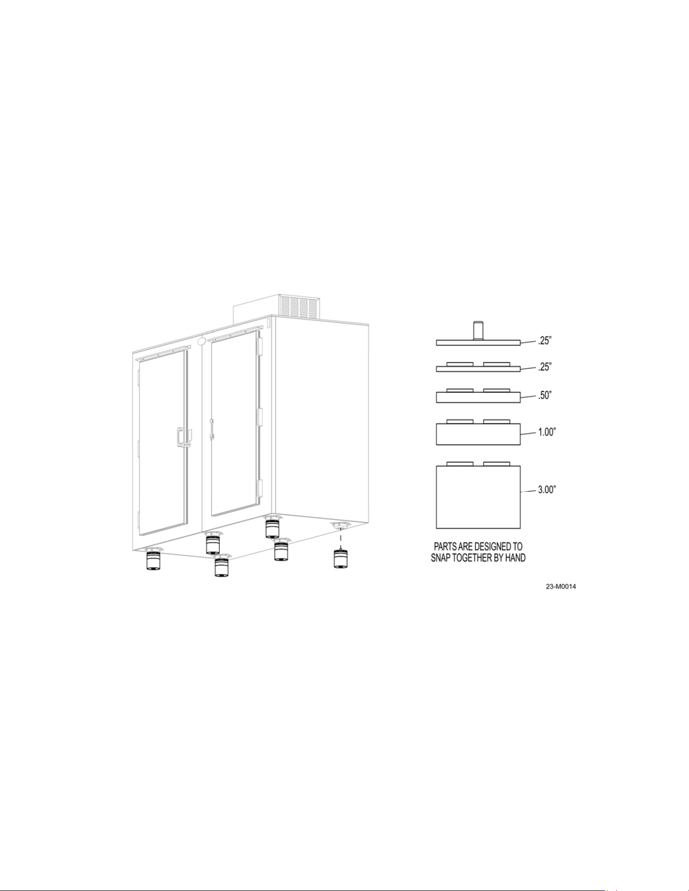
3.5 NSF Spacer Kit
R290 units shipped in the USA can only be certified as NSF compliant by the addition of the
leveling kit. This kit is required by NSF to maintain a 6-inch clearance from bottom of unit to the
floor. This kit must be installed on location to maintain compliance.
To install, use a proper lifting device to raise the merchandiser from the ground. Allow enough
room to get the full kit under the skid plates/feet on the bottom of the unit.
DO NOT TIP THE MERCHANDISER beyond 45° of vertical as mentioned in section 3.1. Insert
the stem of the leveling kit into the bottom of the skid plates as shown in Figure 3-5. Lower the
merchandiser, making sure the weight of the unit is equal across all of the feet. Check the level
of the unit in both directions and adjust as necessary.
.
Figure 3-5
16
Section 4 – Operation
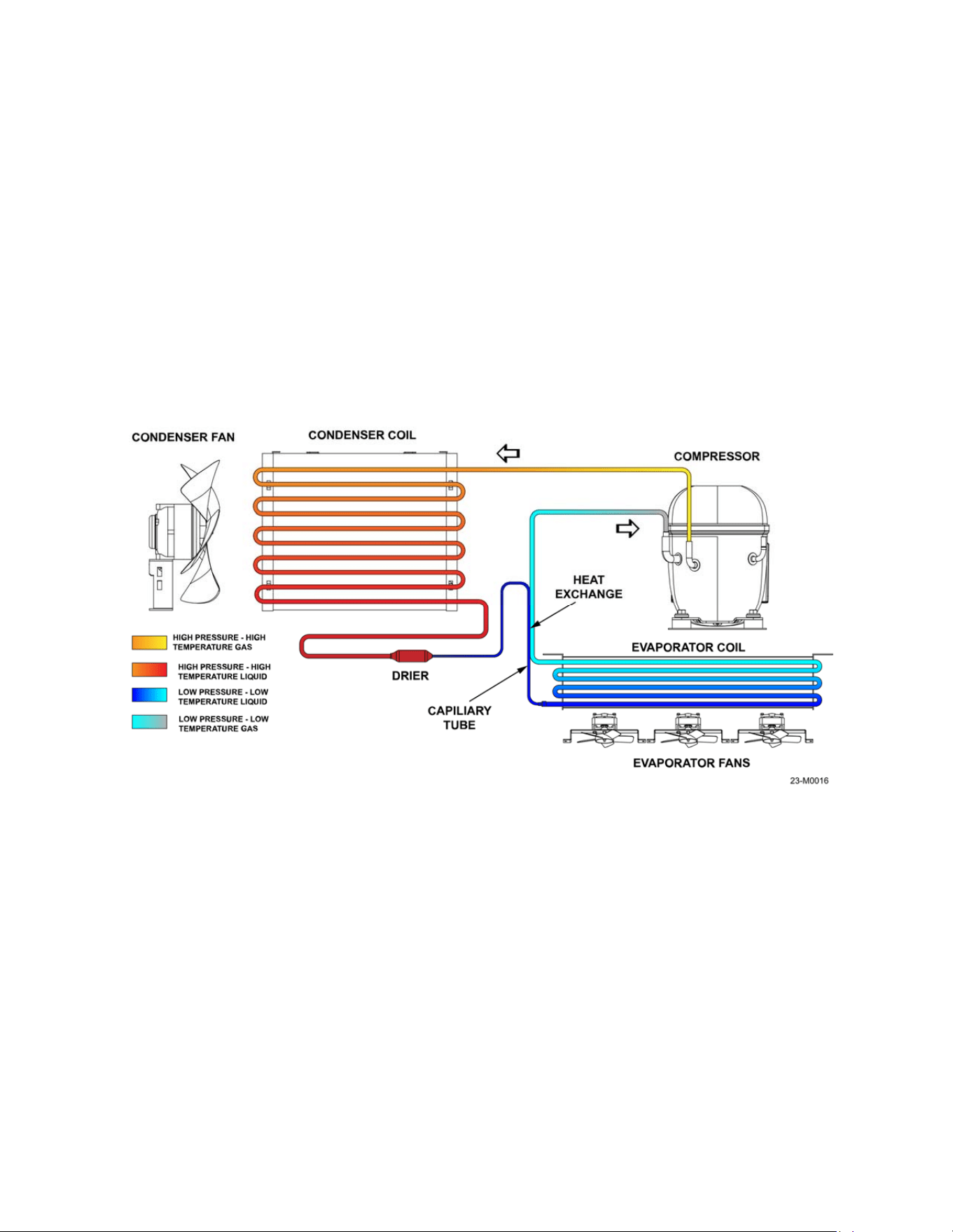
4.1 How the System Works
There are four main elements to a refrigeration system:
The Compressor
The Condenser
The Metering/Expansion Device
The Evaporator
As with any refrigeration system, it cannot create cold – it can only remove heat. If a system is
operating at 0°F and the interior of the unit is 20°F, the 0°F temperature is lower than the 20°F
temperature, so the heat is transferred (absorbed into the cold) from the higher temperature to
the lower one until an equilibrium is achieved.
The compressor: Compression is the first step in a refrigeration cycle. A motor driven
compressor is used to convert the refrigerant medium from an incoming low-pressure, low-
temperature gas to an outgoing high-pressure, high-temperature gas.
The condenser: The condenser (or condenser coil) is one of two types of heat exchangers
used in a refrigeration cycle. The high-pressure, high-temperature gas from the compressor is
routed through the coil and a fan removes heat from the hot refrigerant vapor gas vapor until it
condenses into a saturated liquid state. The medium is now a high-pressure, high-temperature
liquid.
The metering/expansion device: When the refrigerant enters a thermostatic expansion, a
pressure drop occurs. This pressure drop will cause some of that refrigerant to quickly boil,
creating a two-phase mixture (liquid and gas). This phase change is called flashing and the
medium is now a low-pressure, low temperature liquid.
Figure 4-1
17
The evaporator: The evaporator is the second heat exchanger in a standard refrigeration circuit
and it absorbs the heat form the interior of the unit. Remember, even 20°F air has heat in it - if
the evaporator has 0°F (20 degrees colder) refrigerant, the heat will move from warm to cold.
On auto defrost models an evaporator coil has fans pushing air across the coil to remove heat in
the air as it passes over the colder coil. As the heat is absorbed the refrigerant is returned to the
compressor as a low-pressure, low-temperature gas. The cycle continues until the thermostat
tells the system an equilibrium has been achieved, refer to Figure 4-1
4.2 Powering Up
All units are pre-wired with 3-prong plug. The refrigeration unit must be connected to a
dedicated 120-volt, 60 Hz grounded electrical outlet with a circuit breaker. A 20-amp circuit may
be required, due to the shape of the cord plug (see Figure 3-3). Turn the unit on with the power
switch located under the compressor cover. After a 2-minute delay, the compressor and the
condenser fan should start. The evaporator fans and the interior light (if equipped) will
operate immediately when power is applied. The condensing unit will continue to run until the air
temperature in the cabinet reaches the temperature set point on the controller.
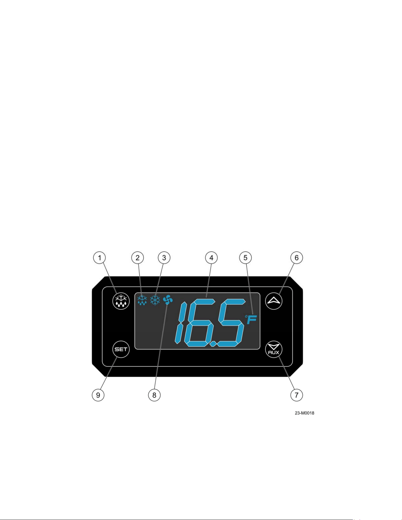
4.3 Controller Operation
The controller is located under the compressor cover on the top of the unit, refer to Figure 2-1.
The controller features are described below, refer to Figure 4-2.
1. Defrost button: Used to initiate defrost cycle – see controller manual.
2. Defrost mode: Defrost enabled when on.
Figure 4-2
18
3. Compressor mode: Compressor operating when on, flashing when delaying between
cycles.
4. Temperature display: Display of current temperature, temperature setpoints.
5. Temperature units (°F/°C): Temperature in degrees Fahrenheit or Celsius.
6. UP arrow: Used to display parameter codes or increase the displayed value.
7. DOWN arrow: used to display parameter codes or decrease the displayed value.
8. Fan operation: Fan operating when on, flashing when delayed after defrost.
9. Set button: Used to display target set point and the real set point; in programming mode
it selects a parameter or confirms an operation.
The control also offers monitoring of the operational status of the unit via the icon and digital
temperature display. The controller has been programmed by Leer to operate within the design
parameters of the refrigeration system. The condensing unit will continue to run until the air
temperature in the cabinet reaches the factory set point temperature of -4°F on freezer models
and, with a differential of 4°F (-4 to 0°F) and +36°F, with a differential of 2°F (36 to 38°F) for the
refrigerator units.
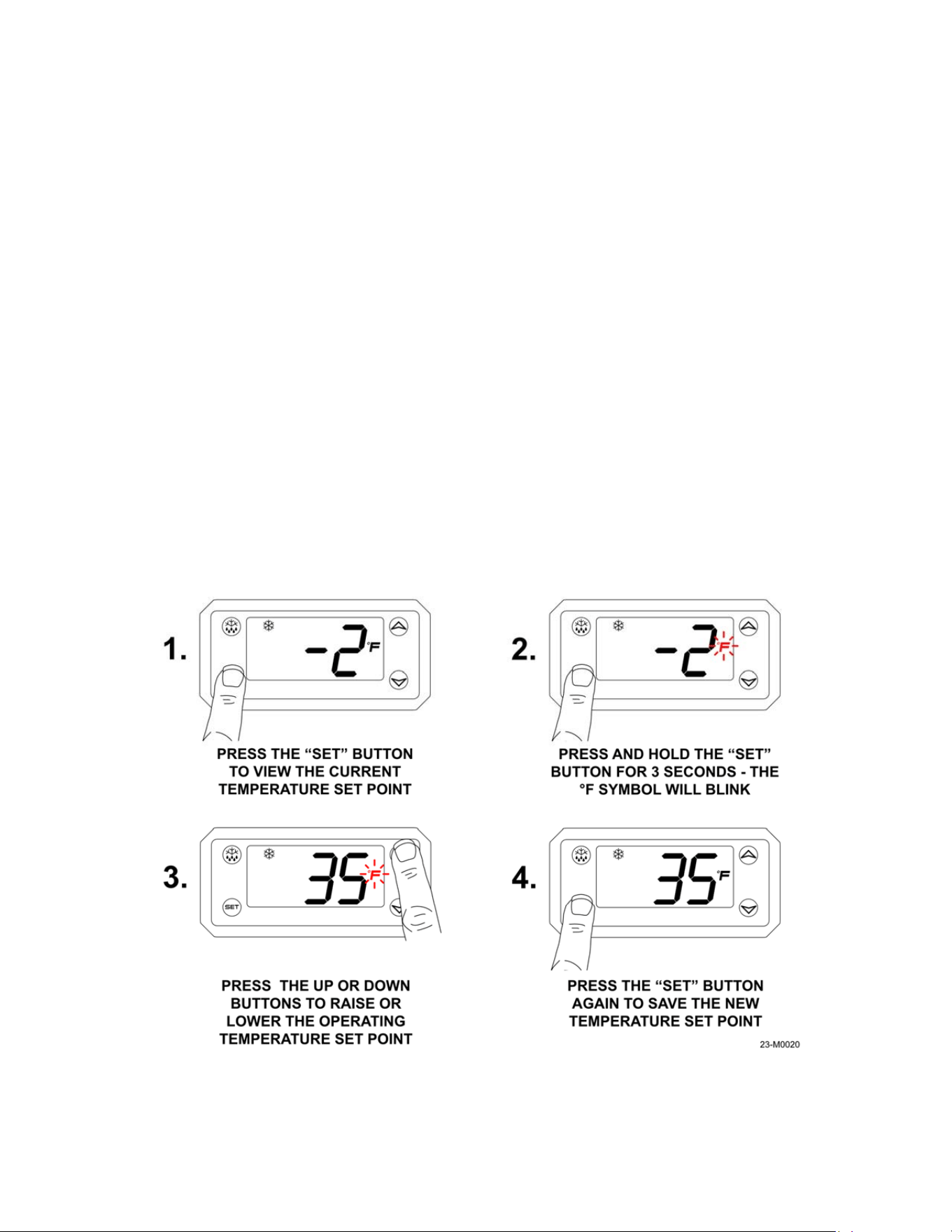
4.4 Changing the Operating Temperature
To change the operating temperature of the remove the compressor cover and locate the
controller, refer to Figure 2-4. The units can be set to operate at a maximum low temperature of
-4°F to a maximum high temperature of +44°F; to view the current set point press the “SET”
button on the controller.
To change the temperature, refer to Figure 4-3.
Figure 4-3
19
NOTE: When operating refrigerator models in sustained temperatures of 32°F or lower,
contact Leer Inc. for alternate controller settings for your model. These alternate settings
may allow your unit to operate more reliably in colder climates.
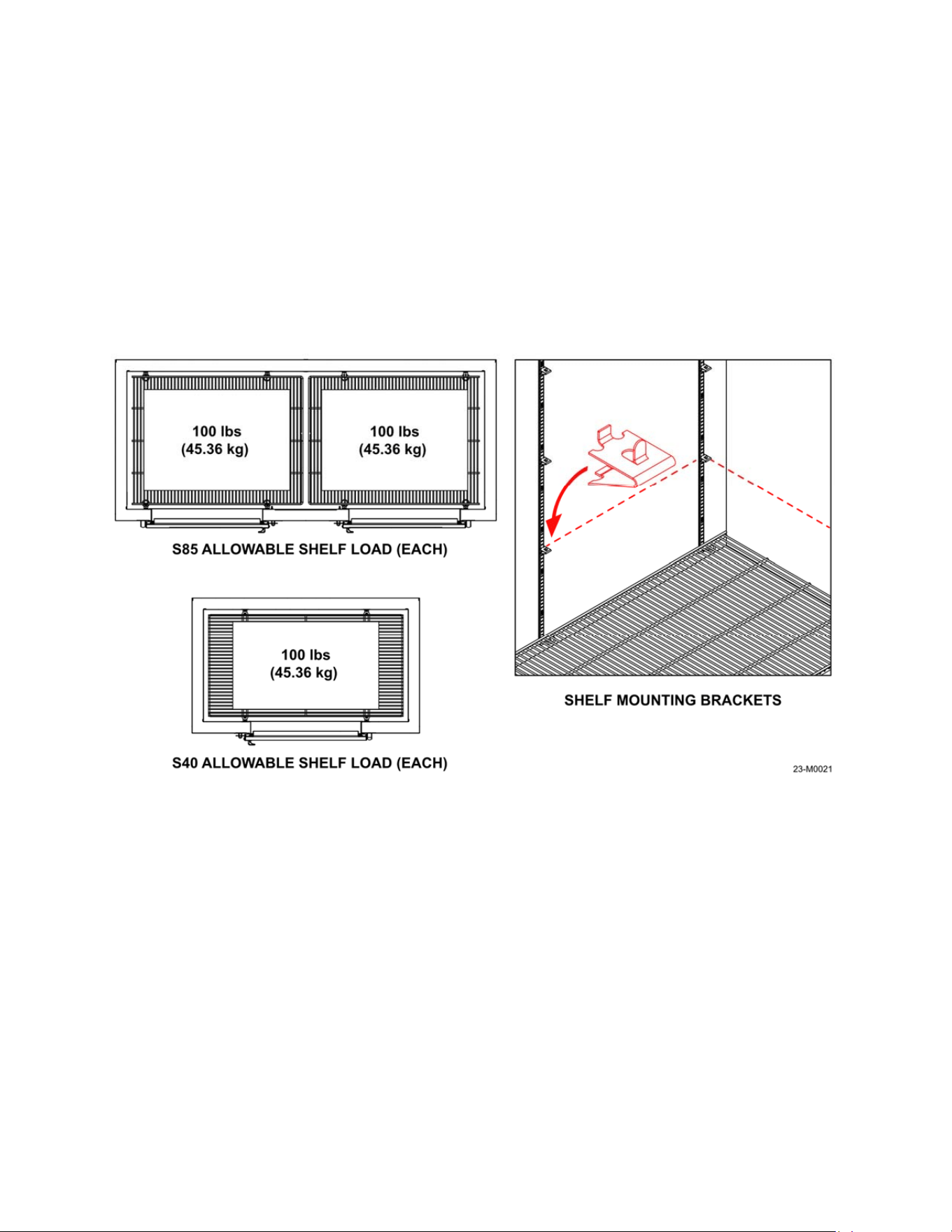
4.5 Adjusting the Shelving
The S85 and S40 units have 4 tiers of adjustable shelving. The maximum load for each shelf is
100 pounds (45.36 kilograms) when all four shelf brackets are set at the same height; refer to
Figure 4-4. The shelves can be adjusted up or down to allow for greater loading flexibility or
removed for bulkier items as needed. Make sure all 4 brackets are secure and at the same level
in each channel before loading any product.
4.6 Loading the Unit
The unit should be pre-chilled before loading any product by allowing it to run for 2-4 hours after
powering up. This will allow the unit to reach the programmed temperature faster once it is
loaded and reduce the risk of products stored melting or softening.
Also, make sure the product going into the unit is cold and at storage temperature if possible.
This will allow the unit to operate more efficiently since it will not have to run to remove heat
from the product being stored in the box.
In very warm and humid climates try to limit the amount and duration of door openings, to
reduce the amount of moisture entering into the box. Damp or humid air that enters the box will
form frost on the colder parts of the interior and products stored inside, reducing the efficiency of
the system.
Figure 4-4
20
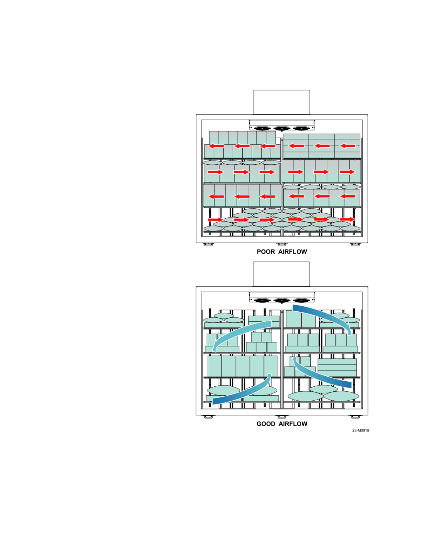
For proper product loading and placement, refer to Figure 4-5. For the best possible
performance of the unit, NEVER place any product on or near the following locations:
1. In front of or directly under the evaporator fans near the ceiling of the unit; this will
reduce the air circulation.
2. On top of or past the tops of
the air duct channels on the
back and sides of the box.
3. In front of or next to the
temperature probe on the left
side of the evaporator
housing. The probe will not
detect the interior
temperature accurately and
the compressor may not
operate as needed.
4. Do not allow products to
overhang past the sides of
the shelves.
5. Do not place items directly
on the floor of the unit. Place
items on the bottom shelf,
which can be installed at the
lowest setting on the
mounting channels.
Always allow for air circulation
around the products being stored
when loading. Packing the interior
too tightly will not allow the products
to chill evenly and maintain a steady
temperature.
Figure 4-5
21
Section 5 - Maintenance
5.1 General Information
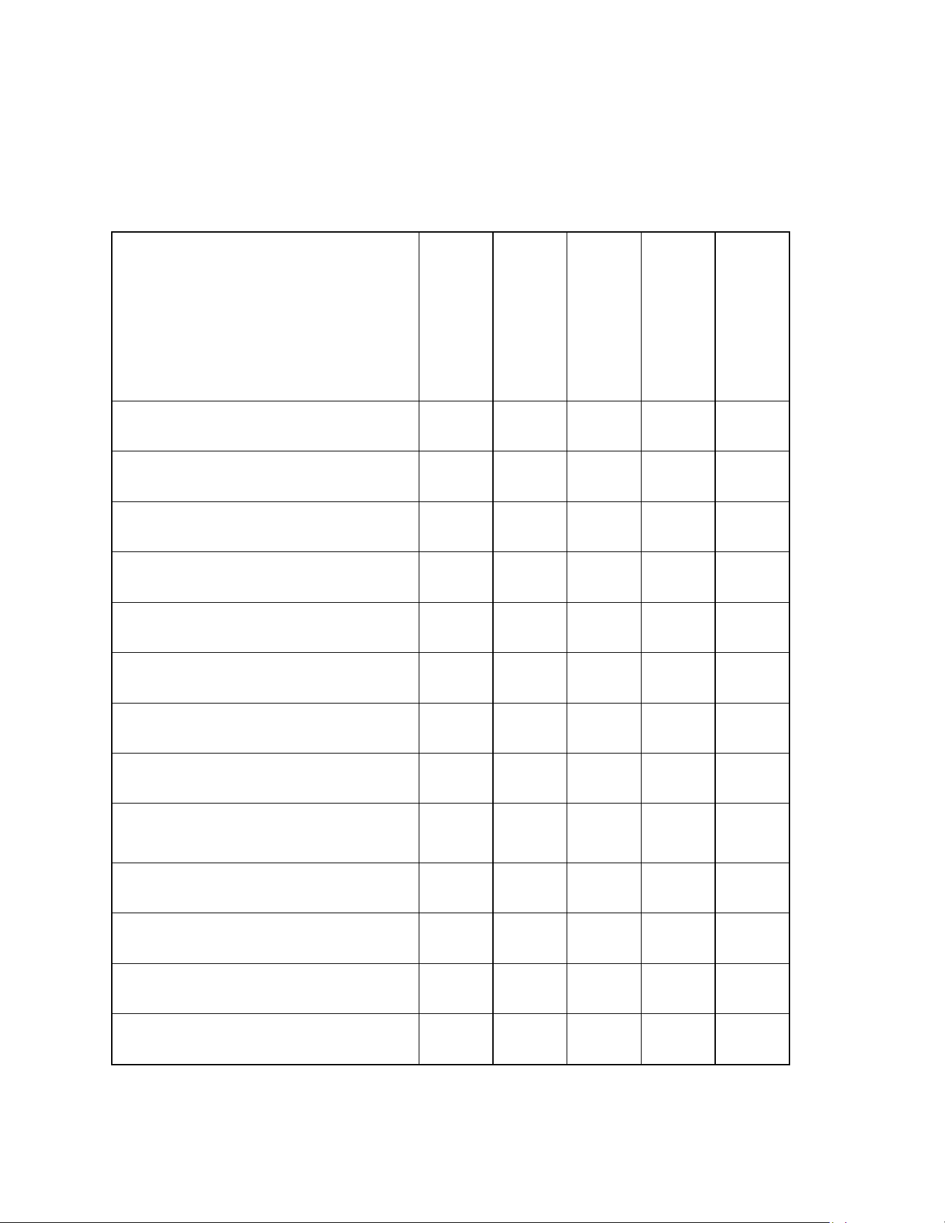
Regular service and upkeep will keep your freezer/cooler operating at peak efficiency.
WHEN THE UNIT IS IN
OPERATION:
EVERY DAY
EVERY 3 MONTHS
EVERY 6 MONTHS
EVERY YEAR
AS NEEDED
Verify operation on the
electronic display
■
Verify the doors close tight and there
are no gaps in the door gaskets
■
Verify drain line is open
and free of ice
■
Remove compressor cover and
inspect for leaks or damage
■ ■
Clean condenser coils and fan
■ ■ ■
Verify evaporator heater is working
on Auto-Defrost models
■ ■
Clean the evaporator coils, fans
and drain pan
■ ■ ■
Check for leaks/broken caulk lines,
repair as needed
■ ■ ■
Check door hinges for worn or
missing components, repair as
needed
■ ■ ■
Perform defrost and clean the
interior and door gaskets
■ ■ ■
Check compressor cut-in and
cut-out temperatures
■
Check interior temperature
and perform calibration
■
Clean the exterior
■ ■
22
NOTE
: Component parts shall only be replaced with like components. Maintenance and
repair of the electrical and refrigeration systems should only be done by trained and
qualified personnel. Disconnect power before performing service, certain models may
contain multiple voltages.
5.2 Cleaning the Unit
In corrosive environments such as coastal regions the unit should be cleaned as needed. When
cleaning the interior of the unit, use dilluted household dishwashing detergents with low or no
odor,followed with a clear water rinse.
DO NOT use detergents with strong odors (i.e. citrus based cleaners or solvent based cleaners)
or cleaners with abrasive or scouring compounds. They may leave objectionable odors or
particles inside the cabinet which may be absorbed by the product being stored in the unit.
Rinse and allow the unit to air dry with the doors open before returing it to service.
NOTE:
Do not use bleach or ammonia to clean the inside of the unit as it may cause
damage to the evaporator coil aluminum fins.
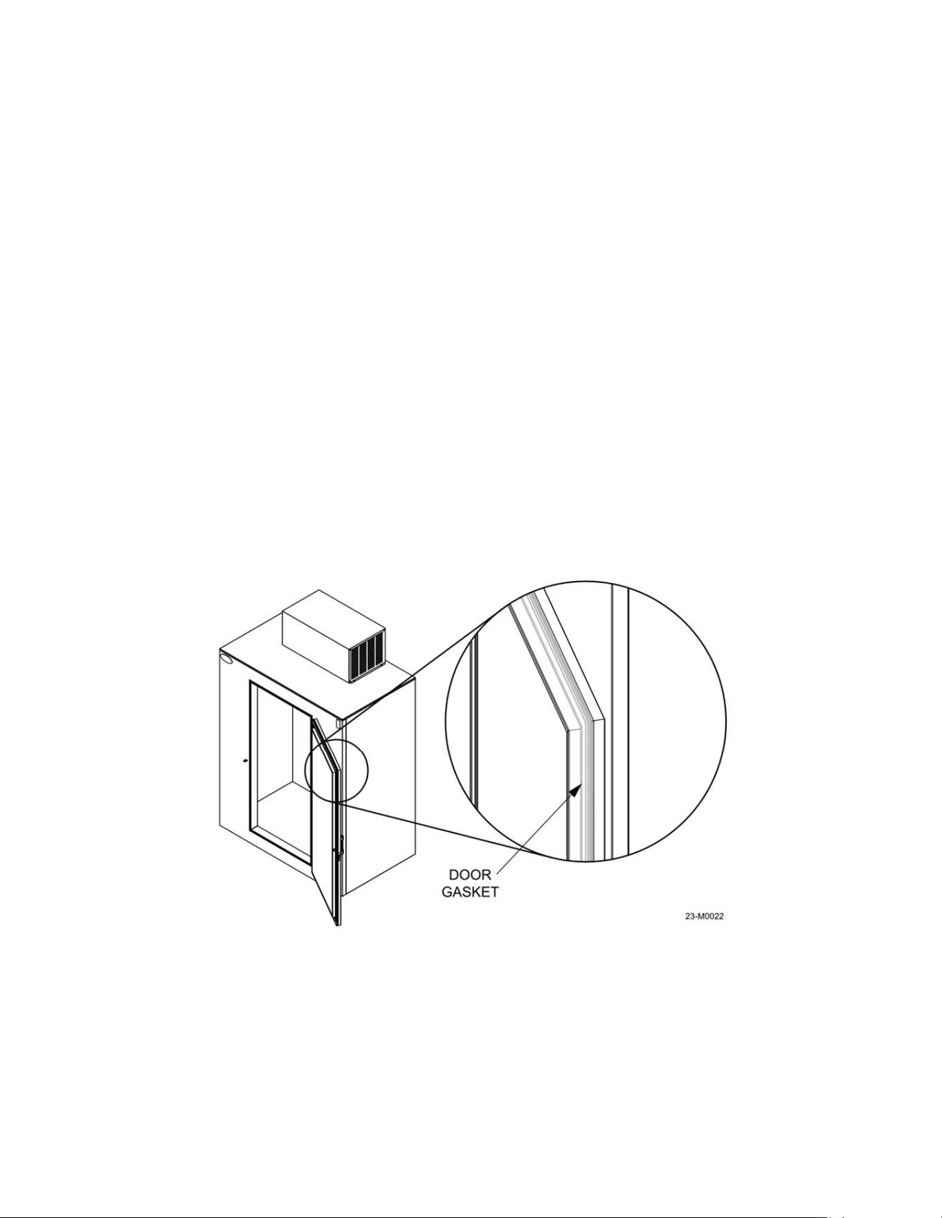
Door gaskets: Door gaskets may mildew and stiffen over time. The gasket is made of a soft,
flexible rubber-like material that can be cleaned using most kitchen and bath cleaners designed
for mildew removal, refer to Figure 5-1. Review manufacturer information and instructions on
any cleaning agent prior to use to determine the cleaner’s compatability with the surface being
cleaned.
Visually inspect the unit for damage, corrosion or loose or missing hardware before washing.
The exterior of the unit can be cleaned with the use of household automotive detergents diluted
in warm water followed with a clear water rinse. Take extreme care to avoid spraying water into
the condensing unit and electrical controls.
Figure 5-1
23
The exterior paint is capable of withstanding the use of standard automotive polishing
compounds and most solvents. If using stronger cleaning agents, they should be tested on a
small, inconspicuous areas prior to application onto visible surfaces of the
5.3 Defrosting
Auto-Defrost models: Auto-Defrost models are designed to be self-defrosting and enter
defrost mode once every few hours on a programmed cycle. During the defrost operation power
is sent to the defrost heating coil and the condensing unit. The evaporator fans do not run.
The heat generated by the defrost coil at the bottom of the evaporator will melt the ice and frost
buildup on the coil tubes and fins. The resulting water will drain through a tube through the back
wall of the box. It is recommended to check the operation and condition of the evaporator coil
and for signs of excessive ice buildup every 3 months.
WARNING:
DO NOT use metal ice
scrapers, ice picks, or hammers as these tools may inadvertently
penetrate through the wall of the cabinet, puncture the evaporator tubing or wiring, and
cause irreparable damage to the unit.
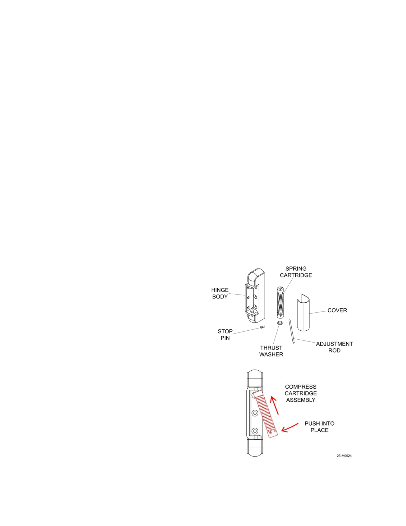
5.4 Door Hinge Install and Adjustment
Hinge assembly:
The hinge components are shown in Figure 5-2; The hinge body, spring
cartridge, thrust washer, adjustment rod, stop pin and cover.
NOTE: Wear eye protection when
doing andy servcing or adjustment of
door hinges.
To replace the hinge spring assembly:
1. Install (No. 220 shown) hinge with
adjustment plate.
2. Assemble the spring cartridge as
shown in figure 5-2. Grease both
ends of the cartridge with petroleum
jelly.
3. Insert the thrust washer over the
round spring mount. Insert the
stationary (square end) of the spring
cartridge over the stationary end and
compress the spring assembly with
the adjustment rod until it can be
placed over the round spring mount
on the hinge, refer to Figure 5-2.
Figure 5-2
24
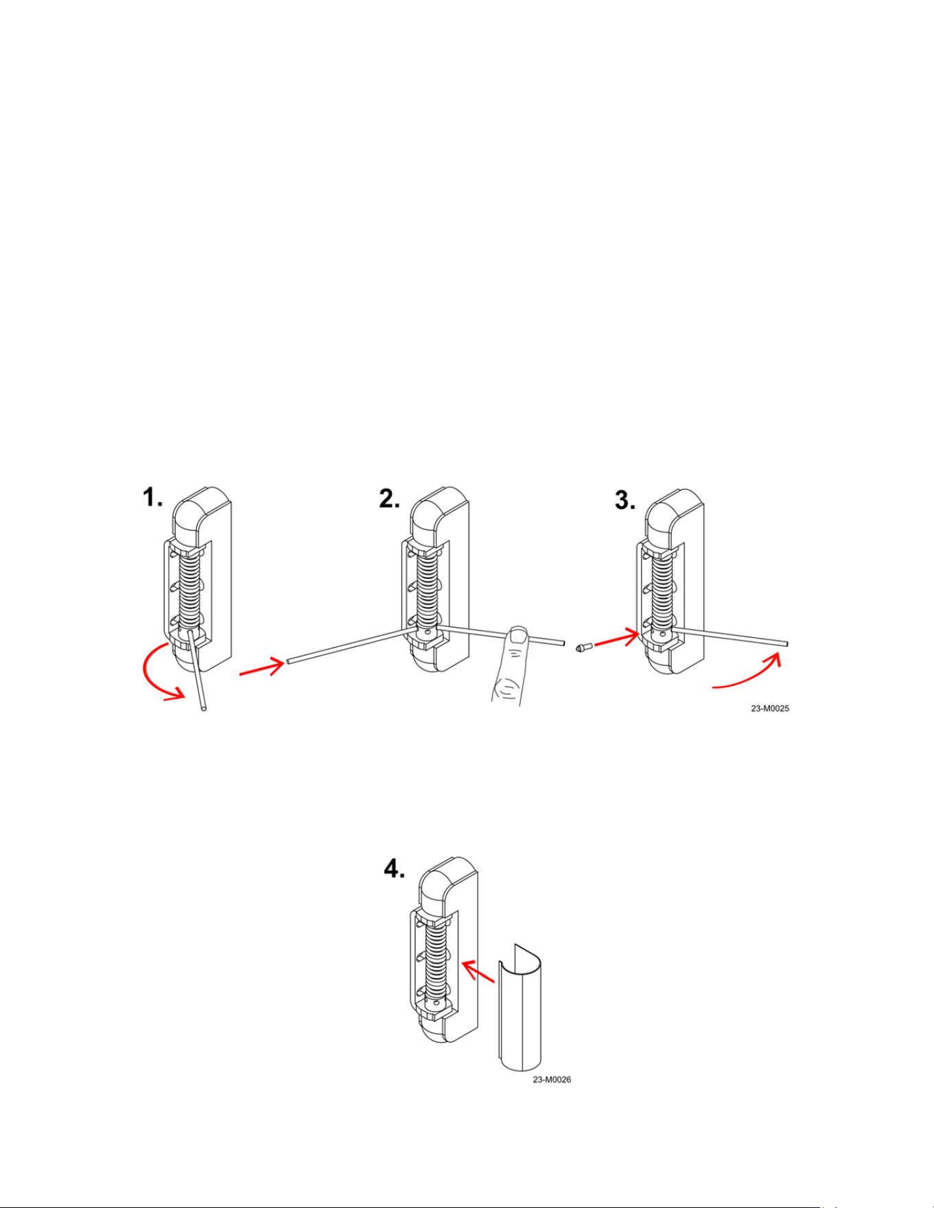
4. After installation, adjust the spring tension.
To adjust the spring tension follow the steps below and refer to Figure 5-3:
1. Insert the adjustment rod in the hole closest to the hinge on the adjustment collar and
turn the rod clockwise until it contacts the other side of the hinge.
2. Hold the adjusting rod in place and insert a second rod. Use this to hold tension, remove
the first rod, and continue rotating the second rod in the adjustment collar clockwise until
it contacts the hinge again, and repeat the process one more time. The maximum
tension is 6 holes or approximately 1 1/4 turns. Do not put the adjustment rod more than
halfway through the adjustment collar.
3. Insert the stop pin into the hole closest to the hinge and slowly release tension until the
pin contacts the hinge. Make sure the stop pin is fully seated in the adjustment collar
before releasing the tension!
4. Install the hinge cover by placing it over the hinge and pushing until it locks in, refer to
Figure 5-4.
Figure 5-3
Figure 5-4
25
5.5 Refrigeration System Maintenance
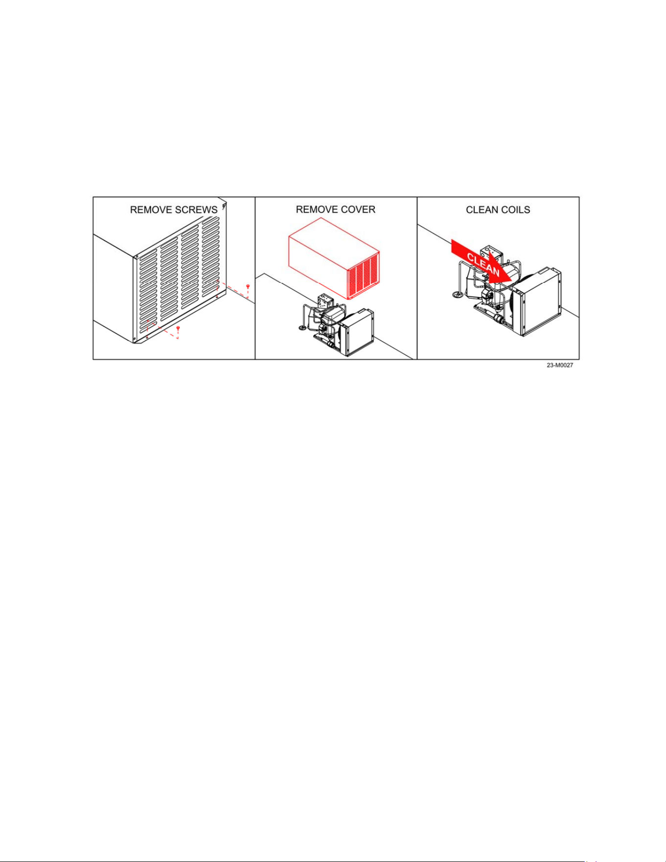
Cleaning the condenser coils: Dirty or clogged condenser coils will cause poor performance
of the refrigeration system by not allowing efficient heat transfer to take place, causing the
compressor to run for longer periods of time. The condenser fan and coils should be cleaned
every three months to ensure proper operation. If operating in very dusty conditions, the
cleaning frequency will need to increase. To clean the coils follow the steps below and refer to
Figure 5-5.
1. Move the power switch to the OFF position and once the unit is powered down,
disconnect the power cord from the source receptacle.
2. Move the unit outdoors if possible.
3. Remove the the screws securing the compressor cover to the unit (4 places, 2 per side).
4. Lift the compressor cover straight up to remove.
5. Blow the coils and fan clean with compressed air in the opposite direction as the airflow
– from the compressor side through the coil as shown.
6. Check the fan for any loose blades. Inspect the coil and fins for any damge or leaks.
7. Repalce the cover and secure it with the screws removed in step 3.
Cleaning the evaporator assembly: Dirty or clogged evaporator coils will cause poor
performance of the refrigeration system by not allowing efficient heat transfer to take place
inside the box. Clogged evaporator coils will not allow cold air to circulate freely, causing
uneven temperatures and possible thawing/melting of product.
1. Move the power switch to the OFF position and once the unit is powered down,
disconnect the power cord form the source receptacle.
Figure 5-5
26
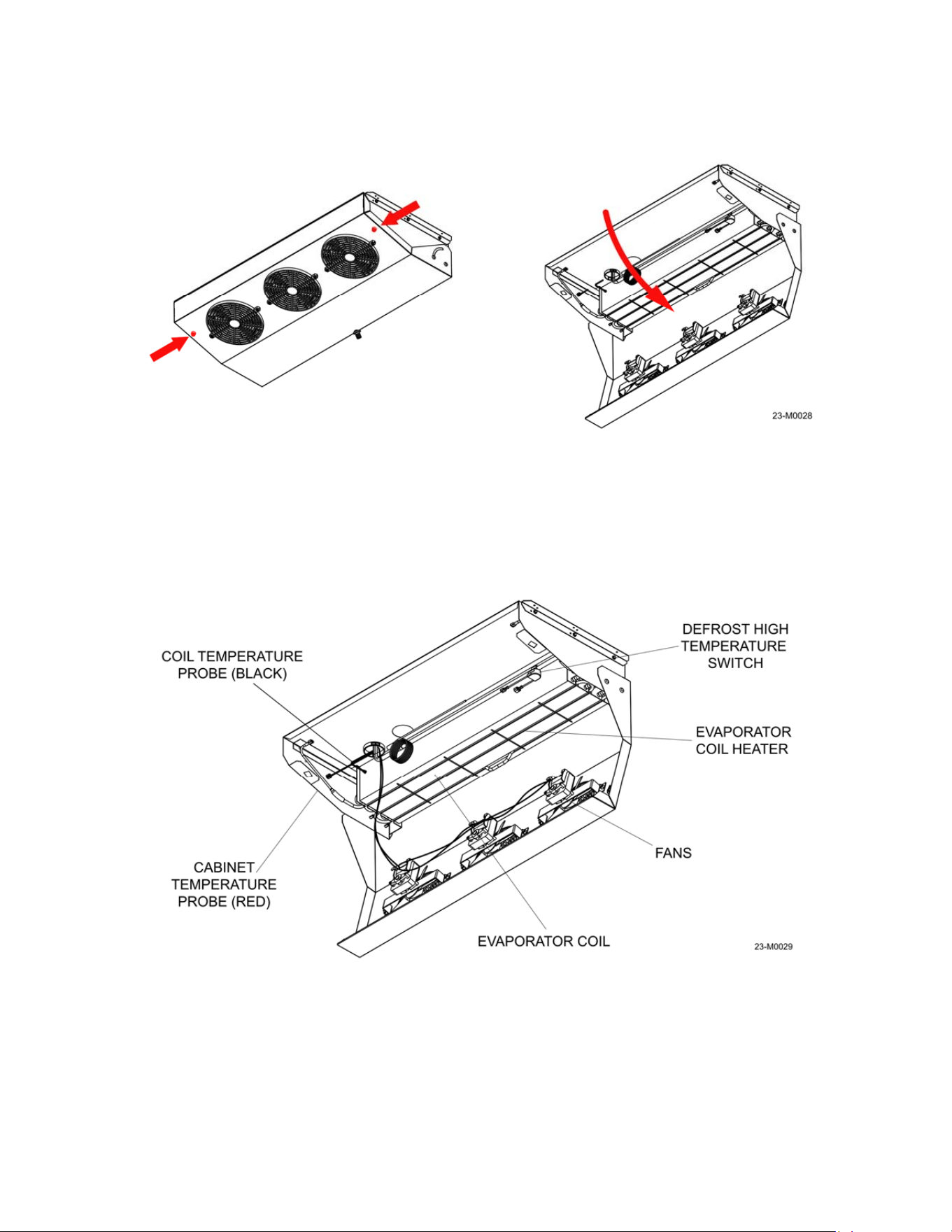
2. Disconnect the drain hose from the evaporator pan. The pan is secured with quarter-turn
screws, one on each side. Push the screw in with a Phillips head screwdriver, rotate and
carefully lower the pan down, refer to Figure 5-6.
3. Check the drain pan for ice, which may be a sign of a blocked drain hose or the heater
coil not functioning properly. Remove any buildup and check the drain hose that is on
the outside of the unit as well for blockage, refer to Figure 2-3.
4. Inspect the evaporator for dust and dirt; clean the coils with compressed air if necessary.
Make sure the evaporator fans spin freely and check them for loose blades or harware;
repair or replace them as necessary, refer to Figure 5-7.
Figure 5-6
Figure 5-7
27
Checking the evaporator coil heater operation: The evaporator coil heater is the main
component that makes Auto-Defrost models possible. The heater operates at pre-set intervals,
usually every 3 hours, to melt any accumulated frost on the evaporator coil assembly. The
compressor and evaporator fans will stop, the heater element will warm up, and the resulting
melt water will drain out of the unit via the drain tube in the rear wall. Excessive ice buildup can
be an indication of a faulty heater, a blocked drain, or both. To check the coil heater operation:
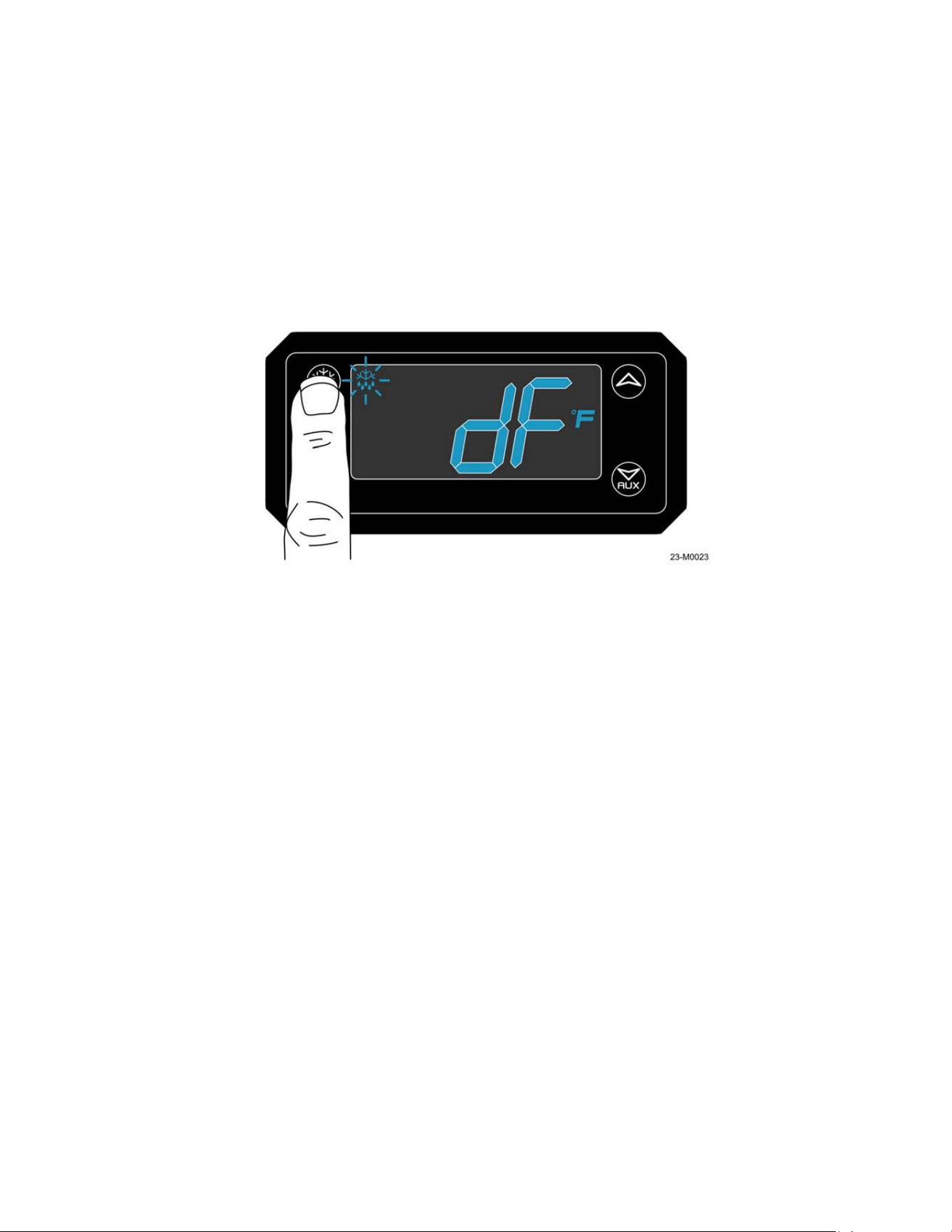
1. Remove the compressor cover to can access to the electronic controller. Initiate the
defrost cycle by pressing the defrost button – the display will show a dripping snowflake
symbol and “dF” for defrost; refer to Figure 5-8.
NOTE: Probe “P2” (inserted into the finned section of the evaporator coil) must be below
the termination temperature set on the controller.
2. Inside the unit, heat should be felt at the drain pan nipple within 2 minutes of defrost
cycle initiation. If not, lower the evaporator pan and fans to carefully check if the defrost
heater is warming the coils.
WARNING:
ELECTRIC SHOCK HAZARD. This unit operates on electrical voltages that may cause
injury or death. Use extreme care when servicing the electrical components of this unit.
3. If the heating element is not getting warm, check for voltage at the yellow wire (position
7) on the back of the digital XR06 controller – it should reflect the incoming line voltage
when in defrost mode. If voltage is not present, the controller should be replaced.
4. Check for voltage before and after the defrost high temperature switch when in defrost
mode. The termination switch must be below 70°F – if the temperature is higher the
switch will remain open and not send voltage to the coil heater. If voltage is present after
the termination switch, the heating element itself may be faulty.
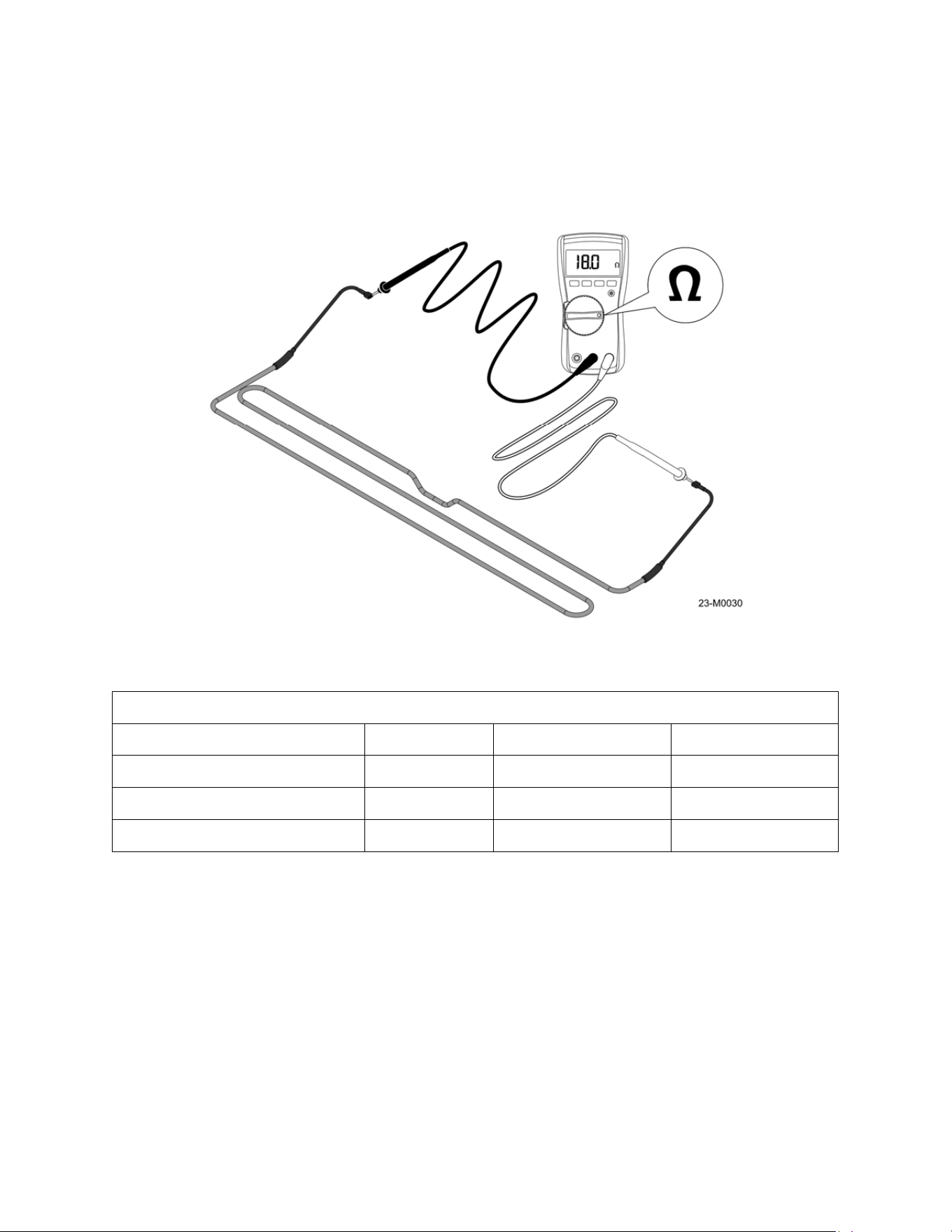
Checking the evaporator coil heater: To check the function of the coil heater:
1. Move the power switch to the OFF position and once the unit is powered down,
disconnect the power cord from the source receptacle.
Figure 5-8
28
2. Locate the spade terminals on each end of the coil heater. Unplug the connectors and
use a multimeter set to Ohms to measure the resistance of the coil heater, refer to
Figure 5-9. Resistance must be checked at 70°F for the best accuracy, with a tolerance
range of +/- 10%; refer to the table for the size and resistance value of the heater. If the
reading is not within the specified range the coil heater must be replaced.
Defrost Heater Resistance @70°F
Heater Size Resistance Range
S40 Freezer 400 watts 36 ohms 39.6 - 32.4 ohms
S40 & S85 Refrigerator 600 watts 24 ohms 26.4 - 21.6 ohms
S85 Freezer 800 watts 18 ohms 19.8 - 16.2 ohms
Figure 5-9
29
Section 6 - Troubleshooting
6.1 Troubleshooting Tables
Some of the problems with your Leer unit can be solved by using the troubleshooting table. Use
extreme care when diagnosing the unit if the cover on the refrigeration system is removed.
WARNING:
ELECTRIC SHOCK HAZARD. This unit operates on electrical voltages that may cause
injury or death. Use extreme care when servicing the electrical components of this unit.
If a problem cannot be resolved after consulting the table call Leer technical service at 1-800-
766-5337.
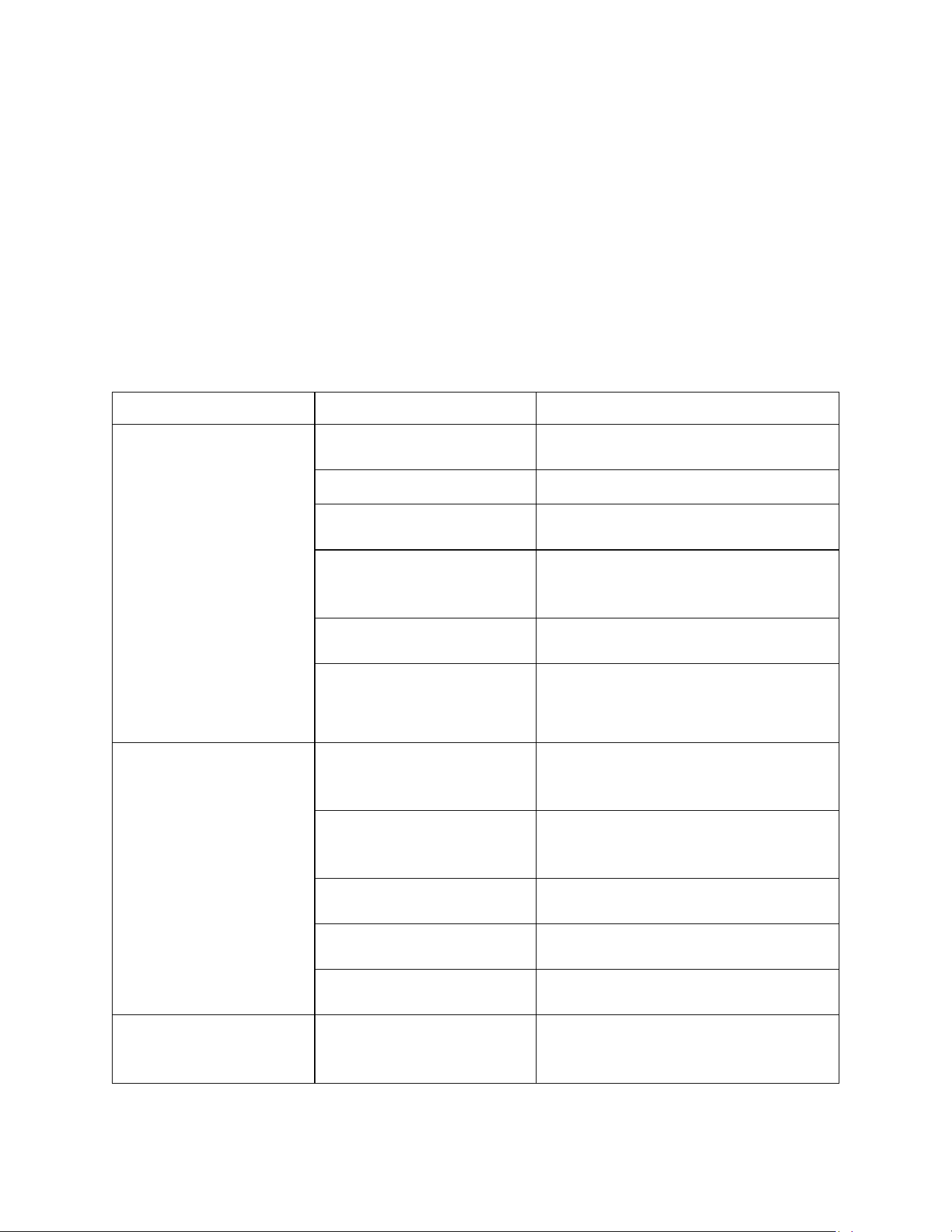
Problem Possible Cause Action
Unit is not
operating.
Power switch located on the
controller box turned off.
Turn power switch on.
Power cord unplugged. Plug in power cord.
Fuse blown / circuit breaker
tripped.
Replace fuse/reset circuit breaker.
dF showing on controller
display (if equipped).
At initial startup the controller will check
to see if a defrost cycle is
needed by the P2 probe temperature.
Receptacle for power cord
not working.
Check receptacle for power with power
meter.
Improper voltage supplied to
cabinet / overload of power
circuit.
Remove extension cords or other
equipment on the same circuit. Check
receptacle voltage with power meter.
Unit not getting
cold but compressor is
operating.
Ambient temperature is too
high from other sources
(exhaust fans or similar).
Try to shield unit from heat sources.
Door not closing properly.
Level the unit.
Check door gasket condition.
Check the door latch mechanism.
Refrigerant leak.
Contact a certified refrigeration
technician to evaluate the unit.
Improper or low input
voltage.
Check power source and verify line
voltage is 115-120VAC 60 Hz
Condenser clogged with
dust/debris.
Clean Condenser (see maintenance
section).
Electronic control blank,
flashing, or displaying
incorrect characters.
Wires disconnected at back
of electronic control.
Check wiring to controller.
30
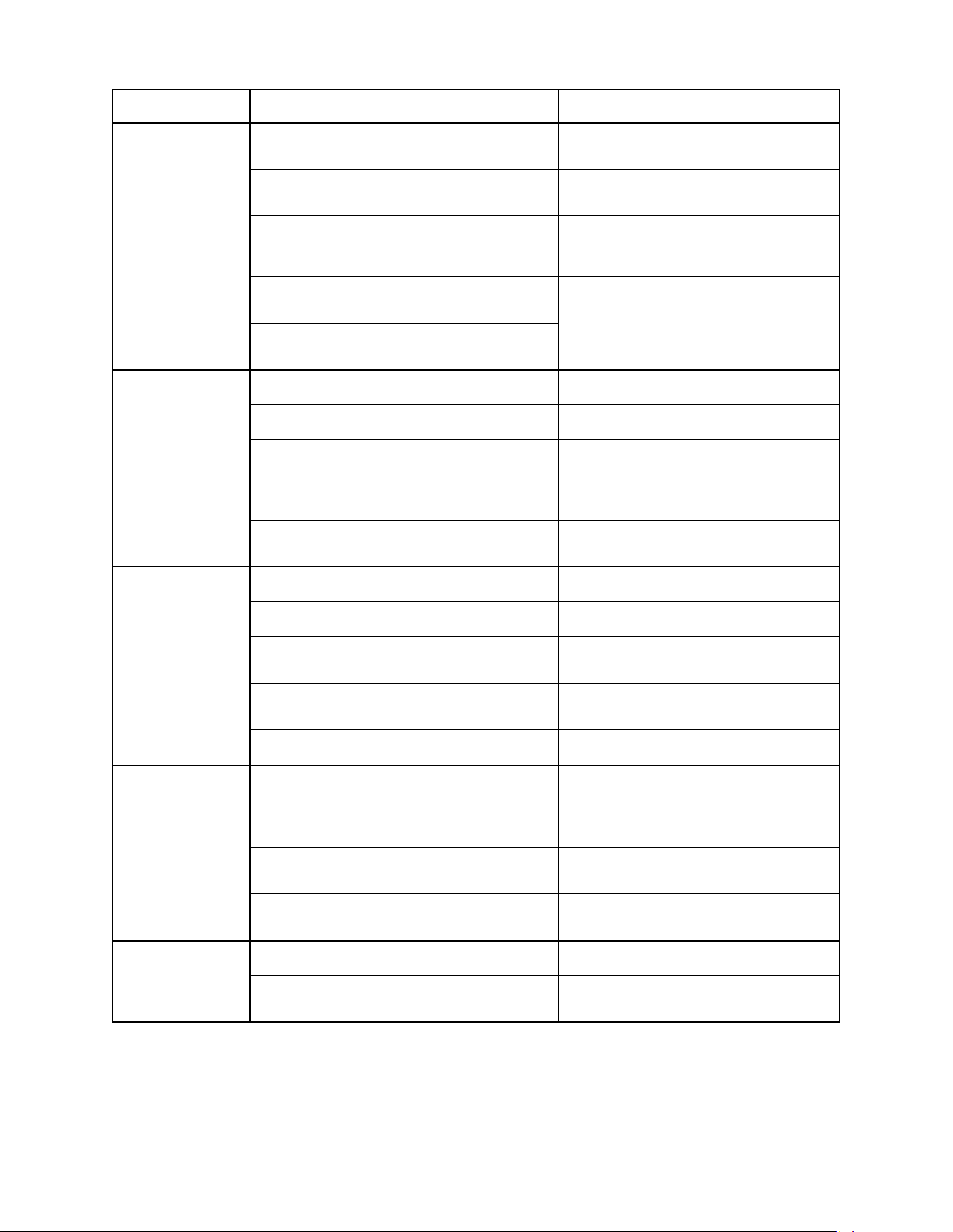
Problem Possible Cause Action
Condensing unit
operating
for a prolonged
period or
continuously.
Unit loaded with excessive amount of warm
product.
Allow enough time for product to cool
down.
Prolonged door opening or door ajar.
Close door when not in use. Avoid
prolonged door openings.
Door not closing properly.
Level the unit.
Check door gasket condition.
Check the door latch mechanism.
Condenser clogged with dust/debris.
Clean Condenser (see maintenance
section).
Evaporator coil blocked with ice or frost.
Defrost manually if required (see
maintenance section).
Unit cabinet
temperature too
high.
Electronic control set too high. Adjust control setting.
Poor air circulation in cabinet. Follow instructions for product loading.
Insufficient clearance around cabinet or
ambient temperature too high.
Keep at least 6” (15.24cm) free space
around all sides of the unit.
Make sure the air flow to the
compressor is not blocked.
Condenser clogged with dust/debris.
Clean Condenser (see maintenance
section).
Door does not
close tight.
Unit is not leveled. Level the unit.
Hinges are loose / not adjusted. Adjust / tighten the hinge screws.
Gasket is out of the groove.
Check gasket condition. Adjust position
or replace gasket.
Ice or frost in door opening or latches.
Check door for ice buildup or
obstructions.
Door hinge pins or bushings worn. Check and repair door pins/bushings.
Evaporator fan
does not run.
Unit in defrost cycle.
Fans do not operate during defrost
cycles.
Fan wire disconnected. Check wiring.
Fans blocked by ice.
Defrost manually if required (see
maintenance section).
Defrost probe not attached to the
evaporator coil.
Check the location of defrost probe.
Evaporator
cabinet is noisy.
Part(s) loose. Locate and tighten loose part(s).
Tubing vibrating.
Ensure tubing is not in contact with
other tubing or components.
31
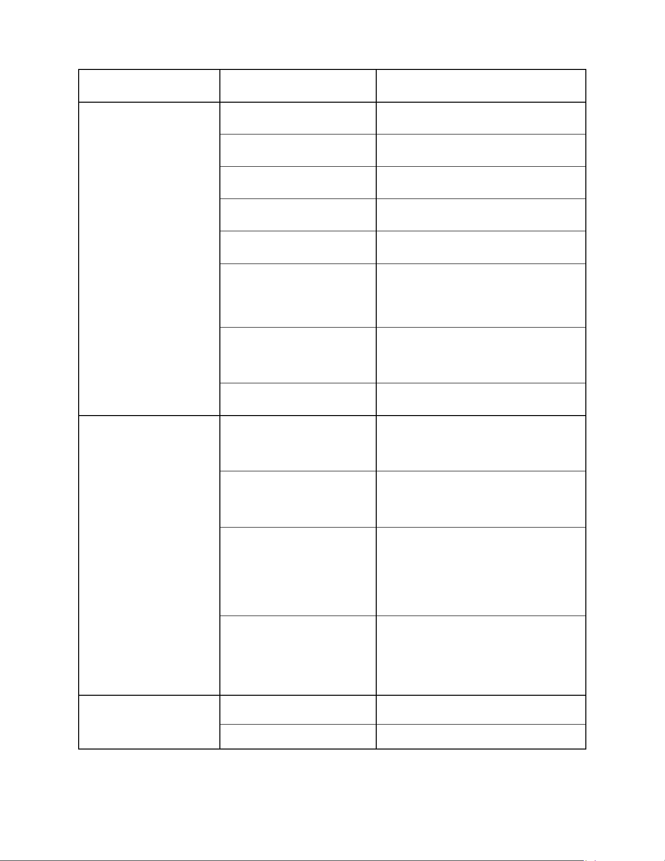
Problem Possible Cause Action
Excessive ice buildup
Inside unit.
Unit is not leveled.
Level the unit; slight angle toward
compressor is desirable.
Door hinges are loose / not
adjusted.
Adjust / tighten the hinge screws.
Gasket is out of the groove.
Check gasket condition. Adjust position
or replace gasket.
Defrost probe not attached to
the evaporator coil.
Check the location of defrost probe.
Ambient humidity too high.
To prevent condensation, limit the
amount of door openings.
Evaporator fans not working.
Check fan wiring.
Fans blocked with ice from clogged drain
tube, defrost manually.
Failed timer cycle, check controller
pro
g
rammin
g
.
Evaporator coil blocked with
ice or frost.
Check evaporator heat coil for operation
(see maintenance section).
Defrost manually if required (see
maintenance section).
Evaporator drain pan hose
blocked with ice or frost.
Defrost manually if required (see
maintenance section).
Electronic Display Fault
Codes.
P1
Air Probe failure: The control will
override the “P1” functions and cycle the
compressor at 5-minute intervals, until
the probe fault can be corrected.
P2
Evaporator Probe failure: The control will
override the “P2” function and
operate with a timed defrost cycle, until
the probe fault can be corrected.
HA
Maximum Temperature Alarm: The
cabinet air temperature has exceeded
programmed temperature for a period
exceeding 15 minutes. The alarm
will continue to display until the cabinet
temperature drops below the set
maximum level of 39°F.
LA
Minimum Temperature Alarm: The
cabinet air temperature has dropped
below the programmed minimum. This
alarm will continue to display until
the cabinet temperature rises above the
minimum level.
LED lighting not
working.
Light switch is off (if
equipped).
Check if the light switch is on.
Faulty LED lamp. Replace the LED lamp.
32
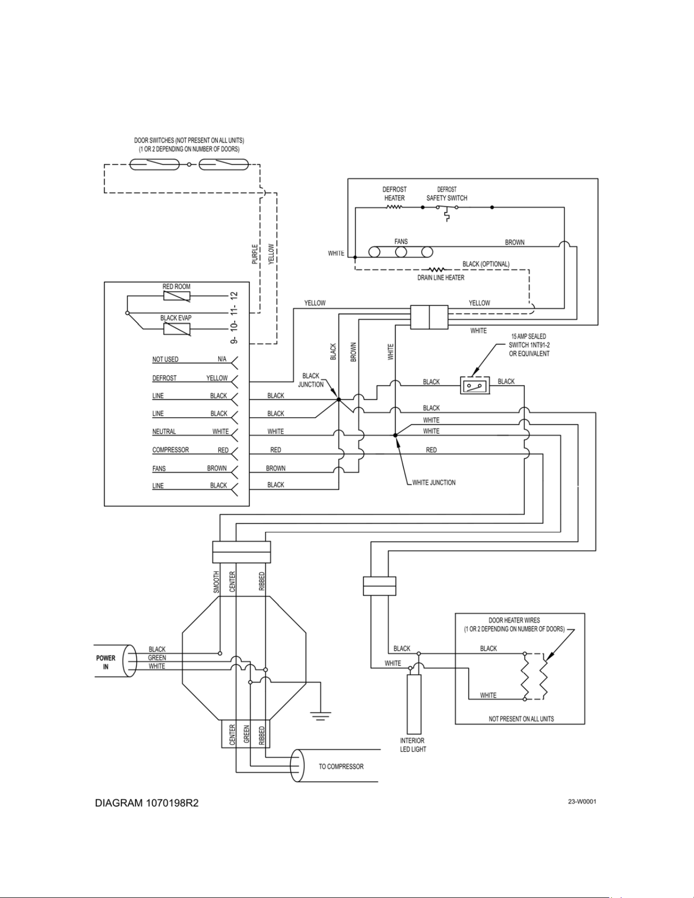
Section 7 – Wiring Diagrams
7.1 Wiring Diagrams.

33
Warranty
Freezer and Refrigerated Storage Units: Seller warrants the unit under normal use and
service, for one (1) year for the component parts (to be shipped by seller), and ninety (90) days
for repair labor from the date of original shipment. The unit compressor motor is warranted for
five (5) years from the date of original shipment. SELLER MUST BE CONTACTED AND
PROVIDED UNIT SERIAL NUMBER FOR WARRANTY CLAIM. This applies only to goods
installed in the United States, Canada or Mexico. Seller’s obligation under this warranty shall be
limited to repair (subject to the limitations below) or replacement of any part(s), F.O.B. Seller’s
factory, which prove(s) defective within the applicable warranty period. Seller reserves the right
to inspect defective part(s) and may at Seller’s discretion require return of part(s) to Seller’s
factory for inspection. The determination as to whether any defect exists shall be made in
Seller’s sole judgement.
GENERAL PROVISIONS APPLICABLE TO ALL WARRANTIES AND PRODUCTS: Seller
shall not be liable for any breach of any express warranty set forth above unless Seller is
informed immediately upon the discovery of defective part(s). The warranties described above
are not assignable and shall operate only in favor of the original buyer/user. In event of any
claim for breach of express warranty, Seller shall be responsible for labor charges for repair or
replacement of any defective part(s) or assembly only for defects reported to Seller within ninety
(90) days after the date of installation. ALL LABOR CHARGES SHALL BE AUTHORIZED OR
APPROVED BY SELLER PRIOR TO THE REPAIR OR REPLACEMENT OF PART(S). In all
other events, Seller shall not be responsible for any labor charges. Labor charges shall only
include standard straight time labor hours at the site of product installation, and shall exclude
charges for travel time, mileage, or other premium charges. These warranties shall not apply to
any goods, or any part thereof, which may have been subject to any damage in transit, accident,
negligence, abuse or misuse, unauthorized alteration or repair, acts of nature or failure to follow
any of the Seller’s manuals or instructions, if in Seller’s sole judgement, such act, omission or
event has detrimentally affected the physical condition, use or operating qualities of the product.
SELLER MAKES NO WARRANTY, EXPRESS OR IMPLIED, BY REASON OF LAW, STATUE
OR OTHERWISE, INCLUDING ANY IMPLIED WARRANTY OF MERCHANTABILITY OR
FITNESS FOR A PARTICULAR USE OR PURPOSE, AND ALL IMPLIED WARRANTIES ARE
HEREBY DISCLAIMED. SELLER SHALL NOT BE LIABLE FOR LOSS OF GOODS,
MERCHANDISE OR OTHER PROPERTY, OR LOSS OF PROFITS, RESULTING FROM
PRODUCT DEFECTS. IN NO EVENT SHALL SELLER’S LIABILITY UNDER ANY
CIRCUMSTANCES FOR ANY BREACH OF CONTRACT OR FOR ANY OTHER CLAIM BY
BUYER AGAINST SELLER EXCEED THE CONTRACT PRICE OF THE GOODS SOLD
HEREUNDER WITH RESPECT TO WHICH SUCH CLAIM ARISES.