
INSTALLATION GUIDE
for the
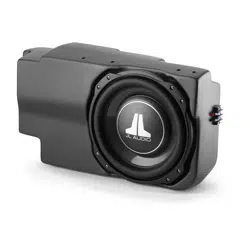
SB-F-EXPED4G/10TW1
SKU# 94688
2018 & Up Ford Expedition & Expedition MAX
• Installation requires appropriate tools and safety equipment.
Professional installation is recommended.
• If you prefer to perform your own installation, please read this
installation guide completely before beginning.
• Before cutting or drilling, check for potential obstacles behind
mounting surfaces.
• Mount this product securely to prevent damage or injury in
severe conditions.
INSTALLATION
DIFFICULTY:
ESTIMATED TIME:
1 HOUR
Enclosure Type: Sealed
Driver Type: 10T W1-2
Nominal Impedance: 2 ohms
Continuous Power Handling: 300 watts (RMS method)
Continued on Next Page
2
5
OUT
OF
SB-F-EXPED4G/10TW1 INSTR_SKU# 011556
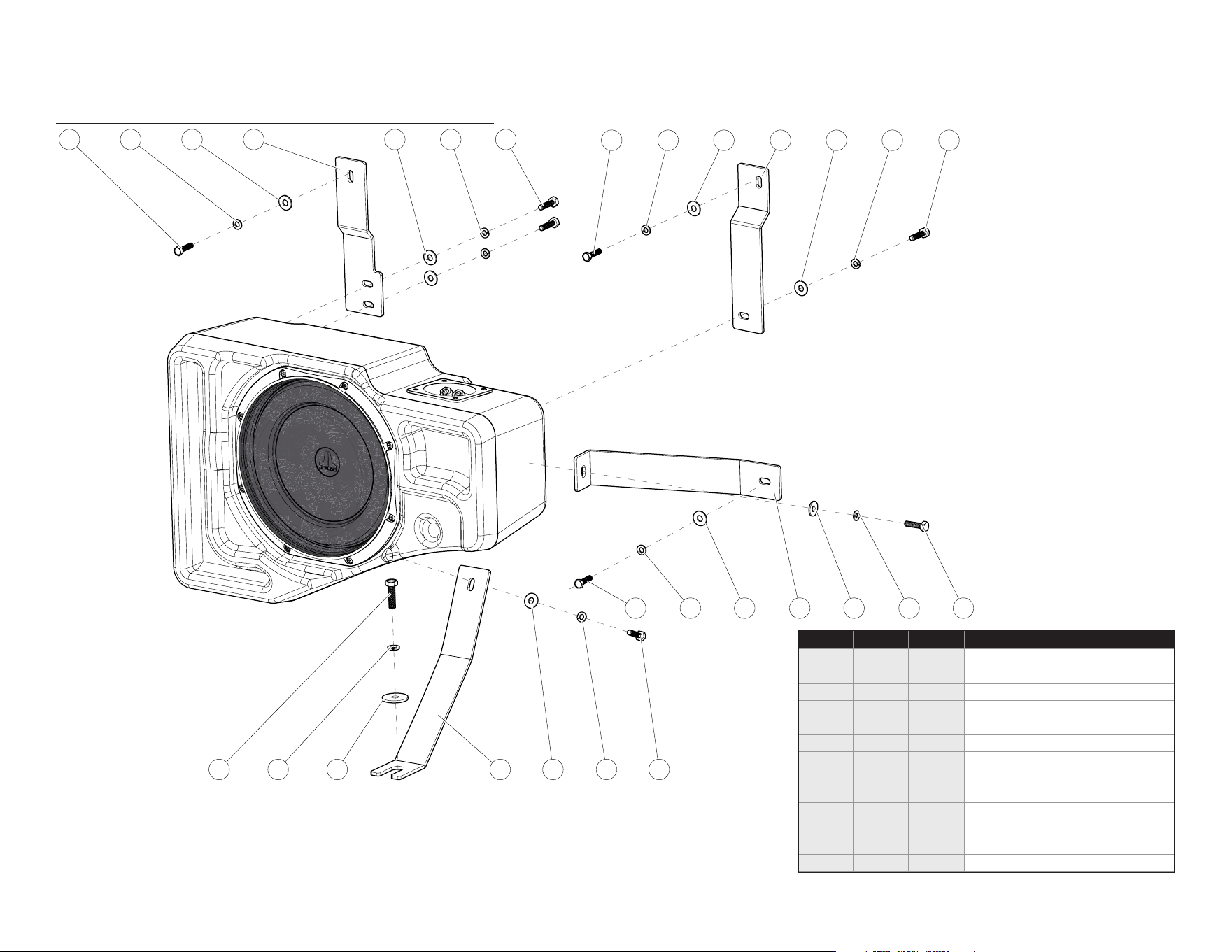
INCLUDED HARDWARE
65312
6
6
1110
5
9
5
3
3
4
7
3
3
2
2
1
1
8 33 5 621
Continued on Next Page
Page 2 • JL Audio, Inc., 2023
SB-F-EXPED4G/10TW1 INSTR_SKU# 011556
BOM ID Qty SKU Description
1 3 154090 M6 x 1mm, 20mm Hex Head Screw
2 3 154091 M6 Split Lock Washer
3 8 151746 1/4” Flat Washer
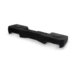
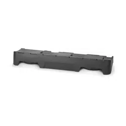
4 1 154199 Top Rear Bracket
5 5 151098 1/4” Split Lock Washer
6 5 150042 1/4 - 20 x 1” Hex Head Screw
7 1 154198 Top Front Bracket
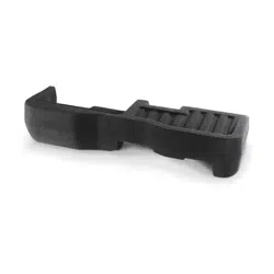
8 1 154197 Front Bracket
9 1 154233 M8 x 1.25mm, 25mm Hex Head Screw
10 1 154234 M8 Split Lock Washer
11 1 153997 5/16” ID, 1-1/4” OD Flat Washer
12 1 154196 Bottom Bracket
13* 1 150249 Foam Tape (not shown)
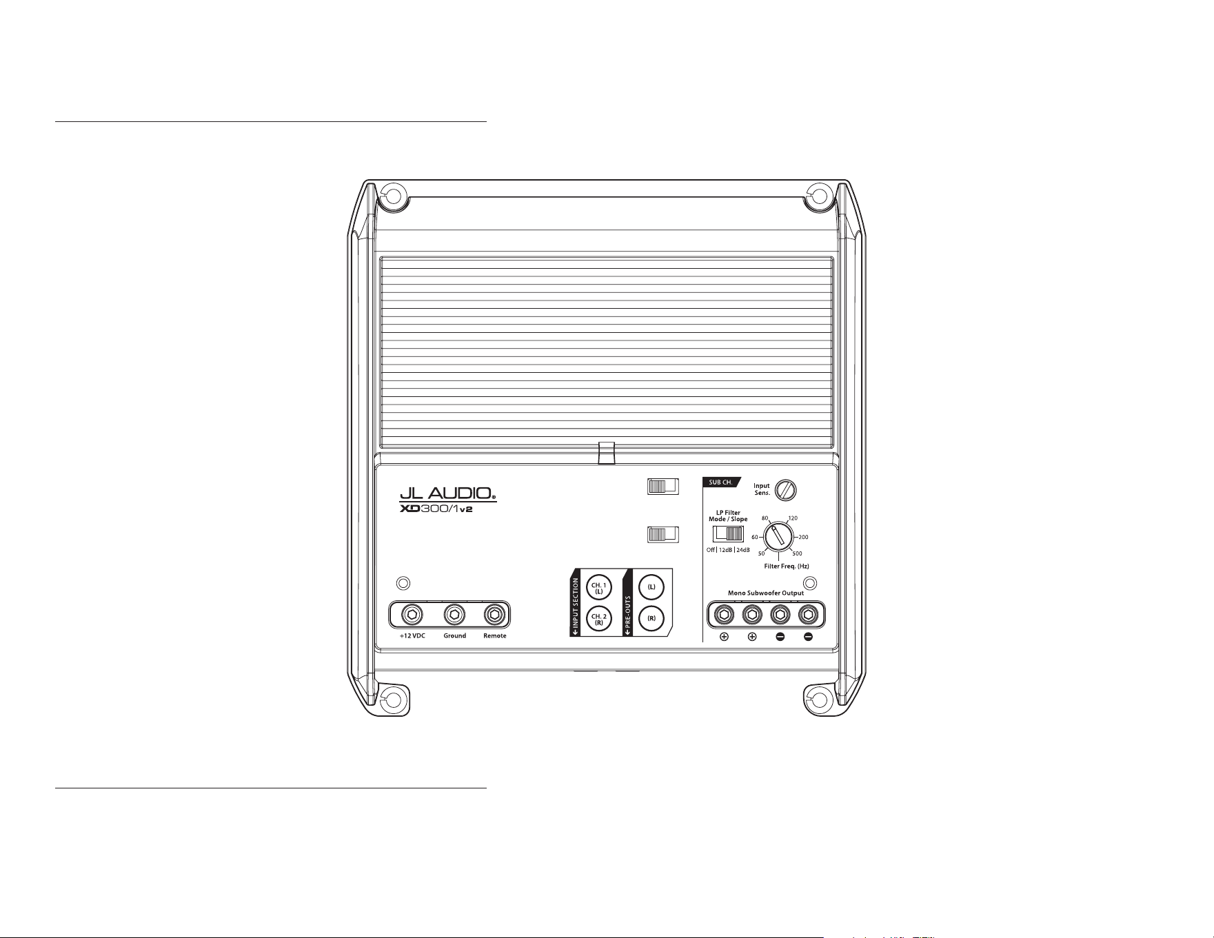
POWER RECOMMENDATION
JL Audio recommends high quality ampliers such as the JL Audio XD300/1v2. The diagram below shows the recommended crossover settings for the XD300/1v2. For a detailed description of the
amplier settings, consult the owner’s manual for the amplier. If another amplier is being used, please reference this illustration and use similar settings on that amplier.
Rem.
|
Oset
|
Signal
Input Voltage
Low
|
High
Turn-On Mode
Monoblock Subwoofer Amplifier
CONNECTIONS
Using quality power, signal, and speaker wire is essential in ensuring the performance of your Stealthbox®. JL Audio recommends using a 4 AWG power kit such as the XD-PCS4-1B for your
Stealthbox® amplier. Other kits are available should you be using more than one amplier. Signal wire such as the JL Audio Premium Audio Interconnect Cables should be used to provide signal for
both channels of the amplier. JL Audio recommends using 12 AWG speaker wire for subwoofers such as our XC-BCS12-25.
Continued on Next Page
Page 3 • JL Audio, Inc., 2023
SB-F-EXPED4G/10TW1 INSTR_SKU# 011556
Page 4 • JL Audio, Inc., 2023 Continued on Next Page
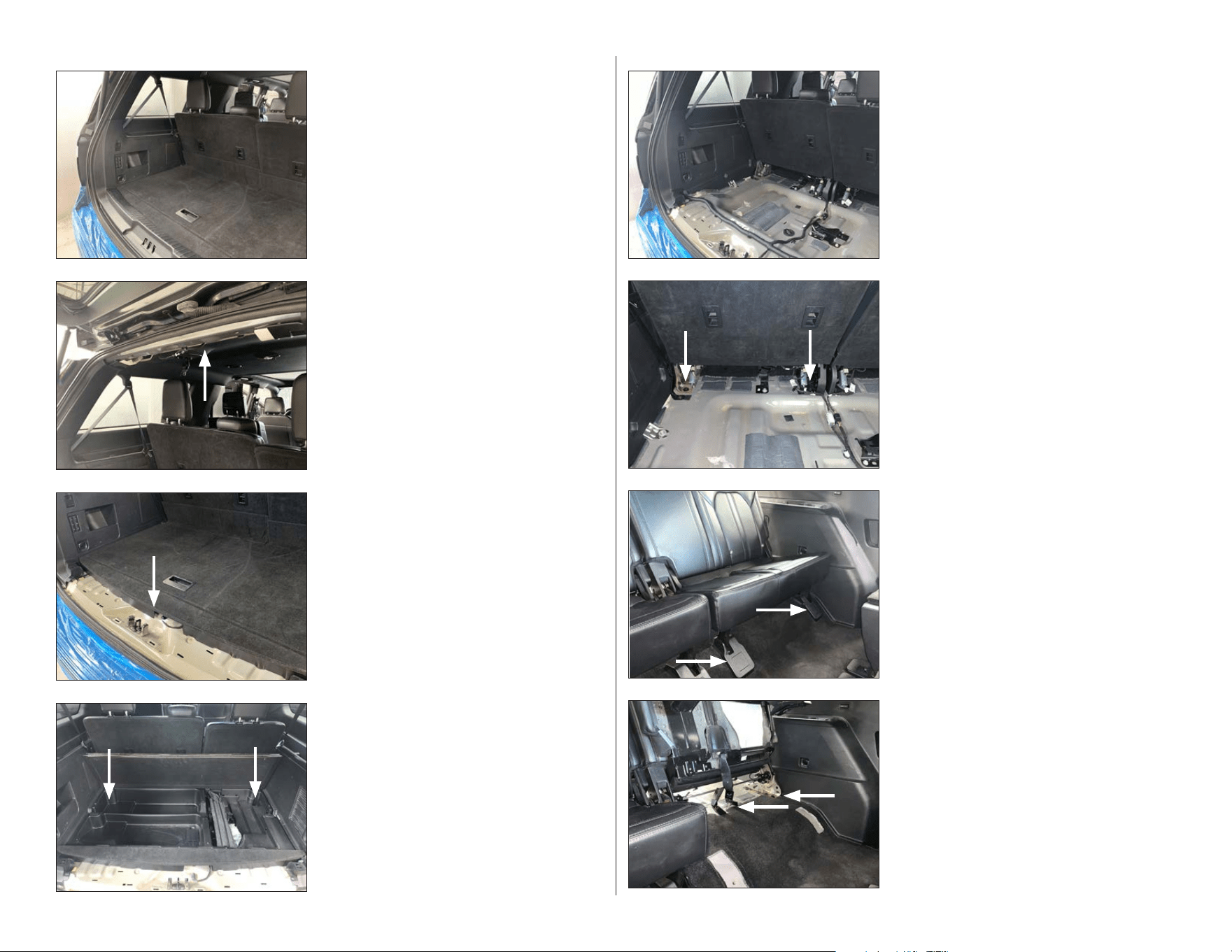
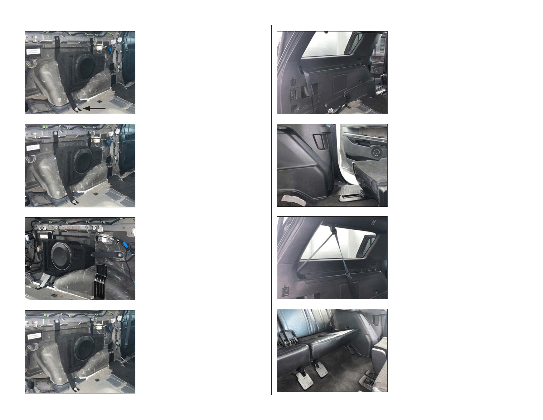
STEP 8
Remove the front seat bolts from the driver’s
side rear seat.
Tilt the rear seat backward. Remove the two
center seat bolts and the one seat belt bolt.
Disconnect the seat belt harness, then remove
the rear seat from the vehicle.
STEP 7
From inside the vehicle, carefully unclip the
screw covers from the rear seat brackets.
STEP 6
Remove the rear seat bolts from the driver’s
side rear seat.
STEP 5
Disconnect the wiring harness from the front
of the storage pocket, then remove the pocket
from the vehicle.
STEP 4
Fold up the cargo floor to access the
storage pocket retaining screws, and remove
the screws.
Remove the jack mounting screw, and remove
the jack from the vehicle.
STEP 3
Carefully unclip and remove the lower cargo
sill panel.
STEP 2
Carefully unclip and remove the upper cargo
trim panel.
STEP 1
Empty the cargo area and the rear seat on the
driver’s side.
SB-F-EXPED4G/10TW1 INSTR_SKU# 011556
Page 5 • JL Audio, Inc., 2023 Continued on Next Page
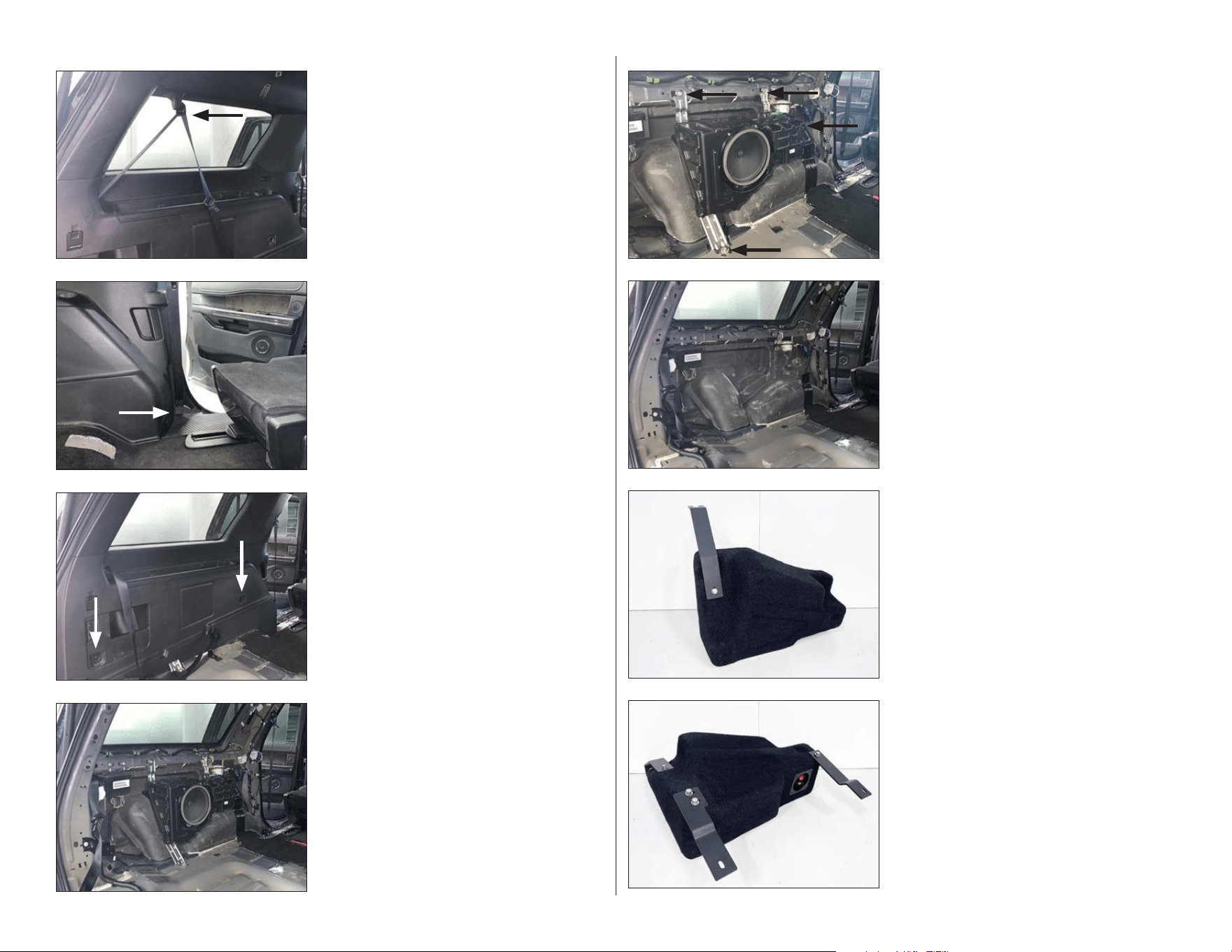
STEP 16
Repeat the process from STEP 15 for the Top
Front Bracket and Top Rear Bracket, as shown.
See the illustration on Page 2 for more detail.
STEP 15
Slide a 1/4” Split Lock Washer and a 1/4” Flat
Washer over a 1/4 - 20 x 1” Hex Head Screw.
Pass the assembly through the slot in the
Bottom Bracket, into the threaded insert on
the back of the enclosure, as shown, and hand
tighten.
See the illustration on Page 2 for more detail.
STEP 14
Disconnect and remove the factory subwoofer.
STEP 13
Remove the factory subwoofer enclosure
mounting screws.
STEP 12
Carefully unclip and remove the C-pillar and
D-pillar, then unclip and remove the side panel
from the vehicle.
STE P 11
Remove the screws from the side panel on the
driver’s side.
STEP 10
Carefully unclip and remove the rear door
sill panel and the seat belt trim panel on the
driver’s side.
Remove the seat belt bolt.
STEP 9
Open the upper seat belt bolt cover, then
remove the seat belt bolt.
SB-F-EXPED4G/10TW1 INSTR_SKU# 011556
Page 6 • JL Audio, Inc., 2023 Continued on Next Page
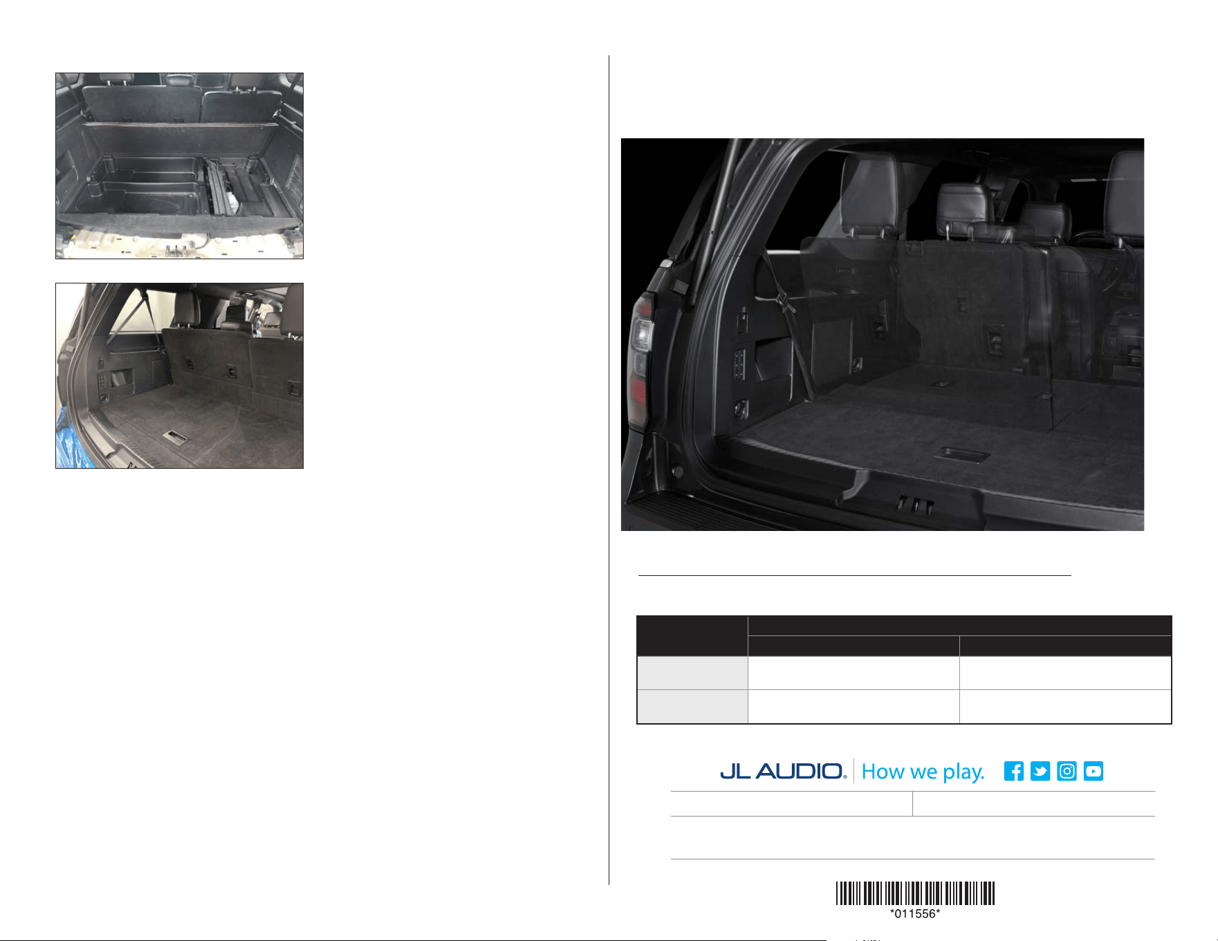
STEP 24
Reinstall the rear seat, seat belt harness, seat
belt bolt, seat bolts, and covers.
STEP 23
Reinstall the rear seat belt bolt and cover.
STEP 22
Reinstall the seat belt bolt, seat belt trim panel,
and rear door sill panel.
STEP 21
Reinstall the side panel, side panel screws,
D-pillar, and C-pillar.
STEP 20
Align the Stealthbox®, as shown, then fully
tighten the three M6 x 1 mm, 20 mm Hex Head
Screws and the M8 x 1.25 mm, 25 mm Hex
Head Screw.
Connect speaker cable to the terminal cup on
the top of the enclosure, and route the cable as
necessary.
STEP 19
Apply Foam Tape to the slotted end of the
Front Bracket where it will contact the vehicle.
Slide a 1/4” Split Lock Washer and a 1/4” Flat
Washer over a 1/4 - 20 x 1” Hex Head Screw.
Pass the assembly through the slot in the
opposite end of the Front Bracket and into the
threaded insert in the front of the enclosure.
Repeat the M6 assembly process to secure the
Front Bracket to the vehicle.
STEP 18
Apply Foam Tape to the landings of the Top
Front Bracket, Top Rear Bracket, and Bottom
Bracket where they will contact the vehicle,
then reinstall the enclosure and the M8
assembly. Slide an M6 Split Lock Washer and
a 1/4” Flat Washer over an M6 x 1 mm, 20 mm
Hex Head Screw, pass the assembly through
the slot in the Top Front Bracket, and into the
factory hole. Repeat the process for the Top
Rear Bracket.
STEP 17
Place the Stealthbox® into position, as shown.
Slide an M8 Split Lock Washer and a 5/16” ID,
1-1/4” OD Flat Washer over an M8 x 1.25 mm,
25 mm Hex Head Screw, then loosely thread
the assembly into into the indicated factory
hole to help hold the enclosure in place.
Align the Top Front Bracket and Top Rear
Bracket to the factory holes in the vehicle, then
carefully remove the enclosure to fully tighten
all four 1/4 - 20 x 1” Hex Head Screws.
SB-F-EXPED4G/10TW1 INSTR_SKU# 011556
Page 7 • JL Audio, Inc., 2023
CONGRATULATIONS!
You have completed the installation for this model! Enjoy your new Stealthbox®!
All specifications are subject to change without notice. “JL Audio®” and “How we play®” are registered trademarks of JL Audio, Inc. “Ahead of the Curve” and its respective logo are trademarks
of JL Audio, Inc.
Printed in USA • ©2023 JL Audio, Inc. • For more detailed information please visit us online at www.jlaudio.com.
(954) 443-1100
www.jlaudio.com
JLA-SKU# 94688 • ver. 01.31.2023 • 10369 NORTH COMMERCE PARKWAY • MIRAMAR, FLORIDA • 33025 • USA
®
MID/HIGH FREQUENCY DRIVER FITMENT
A variety of JL Audio coaxial and component systems will t in the factory speaker locations of your vehicle.
STEP 25
Reinstall the storage pocket and screws.
Reinstall the jack.
SB-F-EXPED4G/10TW1 INSTR_SKU# 011556
STEP 26
Reinstall the cargo sill panel and the upper
cargo door trim panel.
Location / OEM
Speaker Size
Suggested JL Audio Speaker Models
Coaxial Models Component Models
Front Doors /
6 x 9-inch
C1-690x, C1-690tx, C2-690tx C1-690, C3-650
(1)
, C7-650cw
(1,2)
Rear Doors /
6.5-inch
C1-650x
(1)
, C2-650x
(1)
C1-650
(1)
, C2-650
(1)
,
C3-650
(1)
, C7-650cw
(1,2)
1 - Installation may require adaptor, 2 - Component woofer only