
ACTIVESMART™ REFRIGERATOR
INSTALLATION GUIDE
NZ AU BI EU AE HK SG
CONTEMPORARY
FRENCH DOOR REFRIGERATOR FREEZER
RF522A, RF540A & RF610A
BOTTOM MOUNT REFRIGERATOR FREEZER
E372B, E402B, E442B, E522B, RF372B,
RF402B, RF442B, RF522B & RF522W


4
SAFETY AND WARNINGS
READ AND SAVE THIS GUIDE
Use this appliance only for the intended purpose as described in the user guide.
When using this appliance always exercise basic safety precautions including the following:
z
The manufacturer’s installation instructions for product and cabinetry ventilation must be
followed when installing the appliance.
z
To avoid hazard due to instability of the appliance, it must be fixed in accordance with
installation instructions.
z
Keep ventilation openings, in the appliance enclosure or the built-in structure, clear
ofobstruction.
z
Do not use mechanical devices or other means to accelerate the defrosting process, other
than those recommended by the manufacturer.
z
Do not damage the refrigerant circuit.
z
In case of damage to the refrigerant circuit, ventilate the area by opening all windows.
z
Do not operate electrical equipment or any other equipment that may produce arcs,
sparks or flames in the area. Contact your Fisher & Paykel trained and supported service
technician immediately to arrange for the appliance toberepaired.
z
It is hazardous for anyone other than a Fisher & Paykel trained and supported service
technician to service thisappliance.
Electrical
z
This appliance must be installed in accordance with the installation instructions beforeuse.
z
To allow disconnection of the appliance from the supply after installation, incorporatea
switch in the fixed wiring in accordance with the local wiring rules.
z
If the power supply cord is damaged, it must only be replaced by your Fisher&Paykel
trained and supported service technician.
z
When positioning the appliance, ensure the power cord is not trapped or damaged.
z
Do not locate multiple portable socket-outlets or portable power supplies at the rear of
the appliance.
z
WARNING: Do not use electrical appliances inside the food storage compartments of the
appliance, unless they are of the type recommended by the manufacturer.
Water filter
z
The water connection to your Ice & water refrigerator must be installed by a qualified
plumber or Fisher&Paykel trained and supported service technician and comply with all
state and local laws.
z
Installation and use MUST comply with all state and local plumbing codes. Checkwith your
local public works department for plumbing codes. You must follow their guidelines as you
install the water filtration system.
z
To avoid serious illness or death, only connect your water filter to safe drinking water.
z
The water filter cartridge needs to be changed when the replacement indicator icon
illuminates. This will happen every 6 months.
z
If the water filtration system has been allowed to freeze, replace filter cartridge. Failure
to replace the disposable filter at recommended intervals may lead to reduced filter
performance and failure of the filter, causing property damage from water leakage
or flooding.
z
In cases of excessively reduced filter life – we recommend that you consult a local plumber
or your water supplier for advice on suitable filtration requirements for the water supplied
WARNING!
Electric Shock Hazard
Failure to follow these may result in death,
electric shock, fire or injury to persons.
• Read and follow the safety and warnings
outlined in this User guide before operating
this appliance.
WARNING!
Risk of fire/flammable material
• This refrigerator contains flammable refrigerant
isobutane (R600a).
5
ACTIVESMART™ REFRIGERATORS
to your home.
z
Filter replacement is the consumer’s responsibility and will not be covered by the warranty
except in the case of faulty parts or materials within the filter cartridge.
z
If the water filtration system has been allowed to freeze, replace filter cartridge. Failure
to replace the disposable filter at recommended intervals may lead to reduced filter
performance and failure of the filter, causing property damage from water leakage
or flooding.
z
Use new tubing supplied with the refrigerator. DO NOT reuse old tubing from old water
and ice connections.
z
Your water filtration system can withstand up to 827kPa of water pressure. Ensure the
supplied pressure reducing valve is installed before installing the water filtration system.
DO NOT install if water pressure exceeds 827kPa.
z
To reduce the risk associated with property damage due to water leakage or flooding:
z
DO NOT install systems in areas where ambient temperatures may go above 100°F or drop
below 33°F.
z
DO NOT install on hot water supply lines. The maximum operating water temperature of
this filter system is 100°F.
z
DO NOT install where water hammer conditions may occur. If water hammer conditions
exist, you must install a water hammer arrester.
z
Clean the water tanks if they have not been used for 48 hours. Flush the water system
connected to the water supply if water has not been used for 5 days.
z
To reduce the risk associated with choking: DO NOT allow children under 3 years of age to
have access to small parts during the installation of the water filter.
SAFETY AND WARNINGS
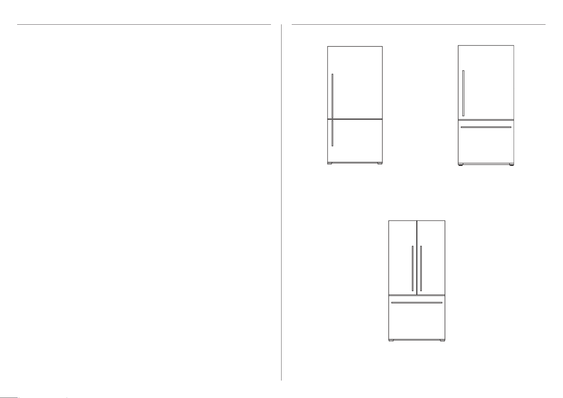
E372B, RF372B, E402B,
RF402B, E442B, RF442B,
E522B & RF522B models
RF522W model
RF522A, RF610A/RF540A &
RF610AZ/AN models
¾” OD x 3/16” ID
Flat Washer
#10-32
Pan Head
Pozi Drive
Wall Plug
#8 x 3/4”
Truss Head
Philips Drive
Self Tapping Screw
¼-20 x ½”
Pan Head
Philips Drive
Machine Screw
M4 x8
Pan Head
Torx Drive
Machine Screw
#10x 3”
Countersunk
Pozidrive
Self tapping Screw
FP Pro Hood Fasteners
6
ACTIVESMART™ REFRIGERATOR
INSTALLATION GUIDE
NZ AU BI EU AE HK SG
CONTEMPORARY
FRENCH DOOR REFRIGERATOR FREEZER
RF522A, RF540A & RF610A
BOTTOM MOUNT REFRIGERATOR FREEZER
E372B, E402B, E442B, E522B, RF372B,
RF402B, RF442B, RF522B & RF522W
Installation guide (1) User guide (1)
USER GUIDE
NZ AU BI EU AE HK SG
ACTIVESMART™ REFRIGERATOR
CONTEMPORARY
FRENCH DOOR REFRIGERATOR FREEZER
RF522A, RF540A & RF610A
BOTTOM MOUNT REFRIGERATOR FREEZER
E372B, E402B, E442B, E522B, RF372B,
RF402B, RF442B, RF522B & RF522W
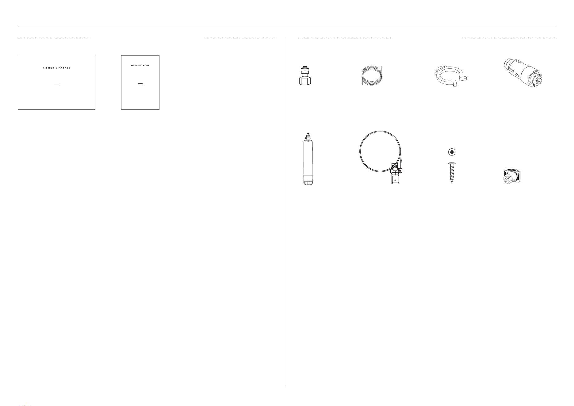
Water tap
adaptor (1)
Short tubing
(1)
SUPPLIED PARTS
MISCELLANEOUS ITEMS PACK WATER FILTER KIT
Wall mounting bracket
+ filter head + tubing
(1)
Collet locking
clip (1)
Pressure limiting
valve (1)
Water filter (1) Valve cover (1)Screws (2)
7
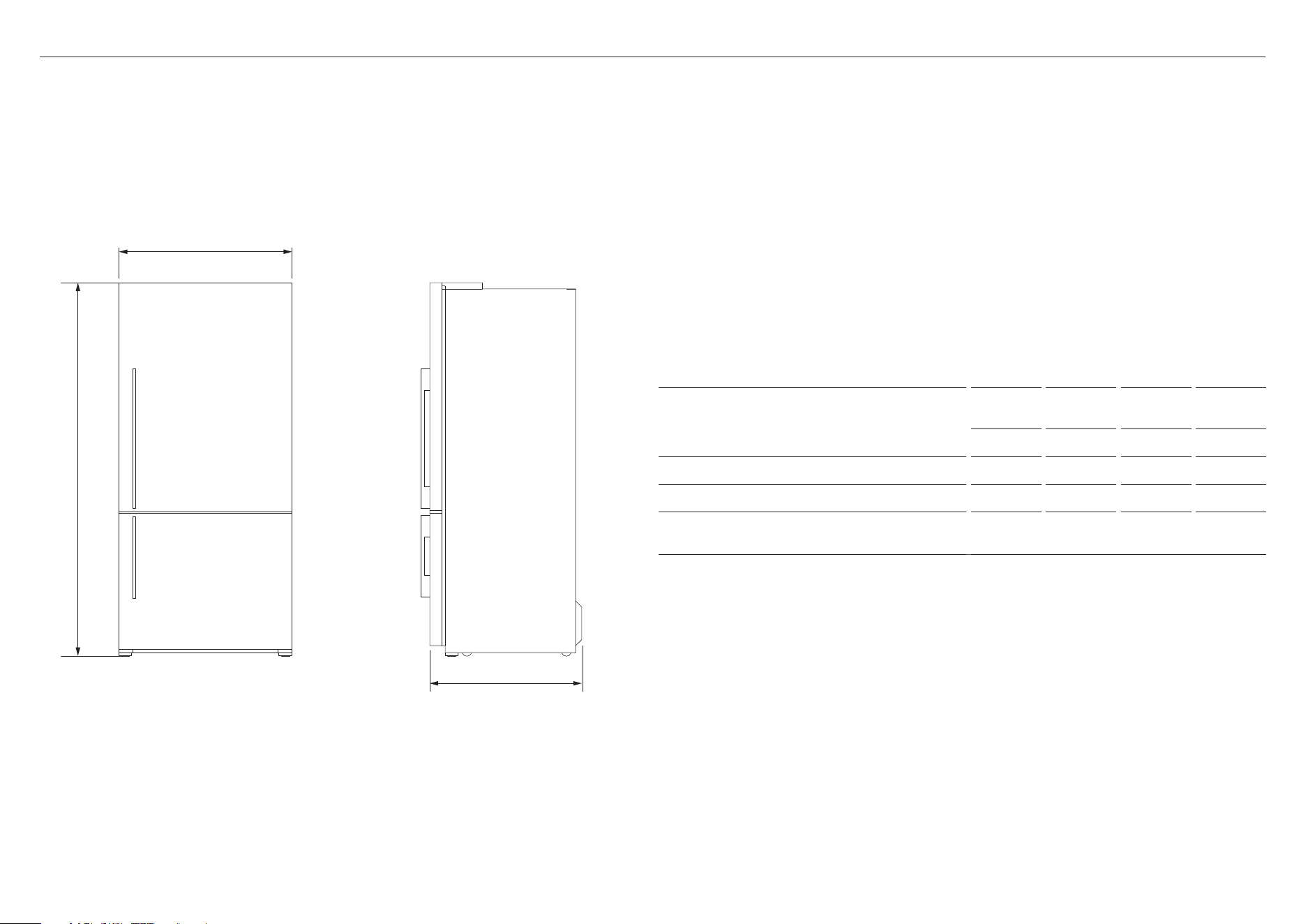
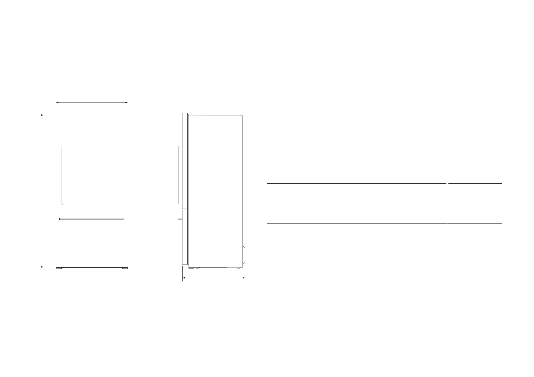
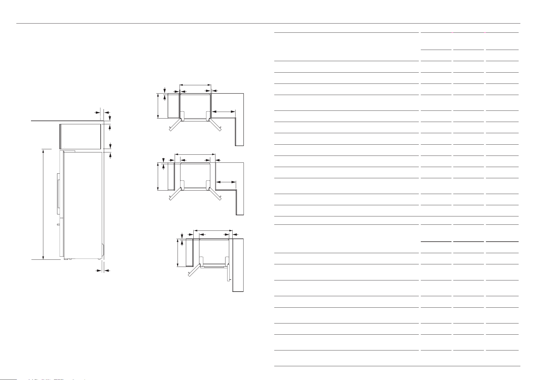
PRODUCT DIMENSIONS
PROFILEFRONT
A
b
c
PRODUCT DIMENSIONS
E372B &
RF372B
E402B &
RF402B,
E442B &
RF442B,
E522B &
RF522B
MM MM MM MM
A Overall height of product 1620 1720 1720 1720
B Overall width of product 635 635 680 790
C Overall depth of product (excludes handle
& includes rear compartment cover)
695 695 695 695
Actual product dimensions may vary by ± 2 mm.
E372B, RF372B, E402B, RF402B, E442B, RF442B, E522B & RF522B models
8
PRODUCT DIMENSIONS
A
b
PROFILEFRONT
c
RF522W model
PRODUCT DIMENSIONS
RF522W
MM
A Overall height of product 1720
B Overall width of product 790
C Overall depth of product (excludes handle & includes rear
compartment cover)
695
Actual product dimensions may vary by ± 2 mm.
9
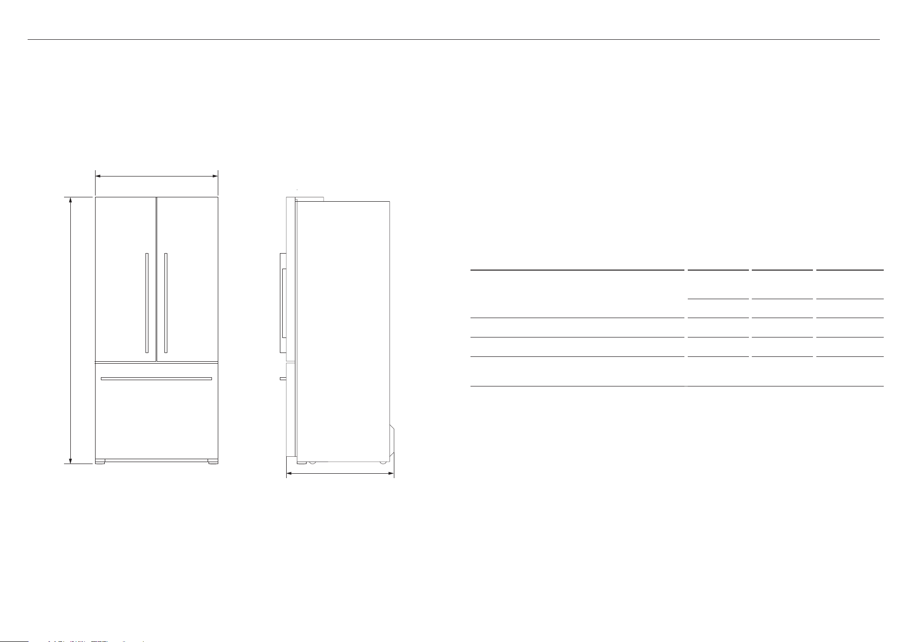
PRODUCT DIMENSIONS
A
b
c
PROFILEFRONT
PRODUCT DIMENSIONS
RF522A
RF610A/
RF540A
RF610AZ/AN
MM MM MM
A Overall height of product 1720 1790 1790
B Overall width of product 790 900 900
C Overall depth of product (excludes handle &
includes rear compartment cover)
695 695 699
Actual product dimensions may vary by ± 2 mm.
RF522A, RF610A/RF540A & RF610AZ/AN models
10
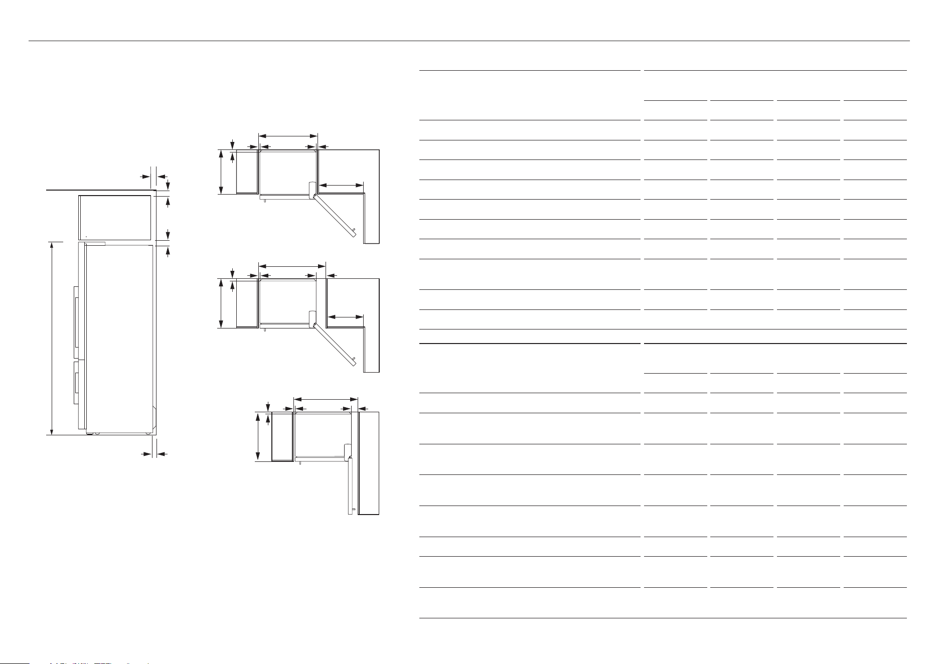
Flush with refrigerator chassis -
full door rotation
Flush with refrigerator door – full
door rotation
Flush with refrigerator door – 90°
door rotation
f
g
k
k
h
a
b
h
n
o
c
k
k
l
m
l
h
h i
d
j
e
CABINETRY DIMENSIONS
CABINETRY DIMENSIONS
(incl. minimum air clearances)
E372B
RF372B
E402B
RF402B
E442B
RF442B
E522B
RF522B
MM MM MM MM
A Inside height of cavity 1645 1735 1735 1735
Flush with refrigerator chassis – full door rotation
B Inside width 675 675 720 830
C Inside depth 620 620 620 620
Flush with refrigerator door – full door rotation
D Inside width 790 790 835 945
E Inside depth flush to flat door n/a 695 695 695
Flush with refrigerator door – 90° door rotation
(for full drawer/shelf access, doors need to be open past 90°)
F Inside width 745 745 790 900
G Inside depth flush to flat door n/a 695 695 695
MINIMUM CLEARANCE DIMENSIONS
E372B
RF372B
E402B
RF402B
E442B
RF442B
E522B
RF522B
MM MM MM MM
H Side clearance 20 20 20 20
I Side clearance – hinge side flush with door –
full rotation
135 135 135 135
J Side clearance – hinge side flush with door –
90° rotation
90 90 90 90
K Rear clearance (including rear compartment
cover)
30 30 30 30
L Vent
(above refrigerator cabinet or around top of
cupboard)
50 50 50 50
M Top clearance – above refrigerator cabinet 50 50 50 50
N Door clearance – hinge side flush with
chassis – full rotation
520 520 555 645
O Door clearance – hinge side flush with door
– full rotation
405 405 440 530
E372B, RF372B, E402B, RF402B, E442B, RF442B, E522B & RF522B models
11
CABINETRY DIMENSIONS
CABINETRY DIMENSIONS
(incl. minimum air clearances)
RF522W
MM
A Inside height of cavity 1735
Flush with refrigerator chassis – full door rotation
B Inside width 830
C Inside depth 620
Flush with refrigerator door – full door rotation
D Inside width 945
E Inside depth flush to flat door 695
Flush with refrigerator door – 90° door rotation
(for full drawer/shelf access, doors need to be open past 90°)
F Inside width 900
G Inside depth flush to flat door 695
MINIMUM CLEARANCE DIMENSIONS
RF522W
MM
H Side clearance 20
I Side clearance – hinge side flush with door – full rotation 135
J Side clearance – hinge side flush with door – 90° rotation 90
K Rear clearance (including rear compartment cover) 30
L Vent
(above refrigerator cabinet or around top of cupboard) 50
M Top clearance – above refrigerator cabinet 50
N Door clearance – hinge side flush with chassis – full rotation 645
O Door clearance – hinge side flush with door – full rotation 530
RF522W model
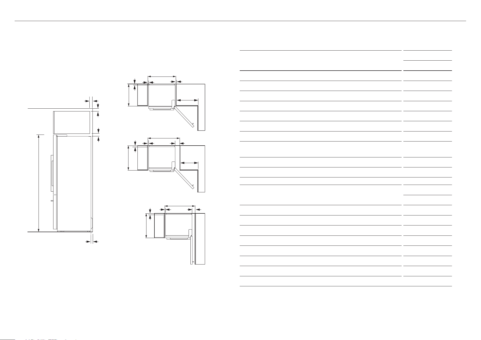
Flush with refrigerator chassis -
full door rotation
Flush with refrigerator door – full
door rotation
Flush with refrigerator door – 90°
door rotation
f
g
k
k
h
a
b
h
n
o
c
k
k
l
m
l
h
h i
d
j
e
12
Flush with refrigerator chassis -
full door rotation
Flush with refrigerator door – full
door rotation
Flush with refrigerator door – 90°
door rotation
f
g
k
k
i
a
b
h
n
o
c
k
k
l
m
l
h
i
i
d
j
e
RF522A, RF610A/RF540A & RF610AZ/AN models
CABINETRY DIMENSIONS
CABINETRY DIMENSIONS
(incl. minimum air clearances)
RF522A
RF610A/
RF540A
RF610AZ/
RF610AN
MM MM MM
A Inside height of cavity
z
Flush with refrigerator chassis 1735 1810 1810
z
Flush with refrigerator door 1735 1810 1810
z
Flush with refrigerator door with handle clearance
(AN & AZ models)
N/A N/A 1835
Flush with refrigerator chassis – full door rotation
B Inside width 830 940 940
C Inside depth 620 620 620
Flush with refrigerator door – full door rotation
D Inside width 1060 1170 1170
E Inside depth flush to flat door 695 695 700
Flush with refrigerator door – 90° door rotation
(for full drawer/shelf access, doors need to be open past 90°)
F Inside width 1015 1125 1150
G Inside depth flush to flat door 695 695 700
MINIMUM CLEARANCE DIMENSIONS
RF522A
RF610A/
RF540A
RF610AZ/
RF610AN
MM MM MM
H Side clearance 20 20 20
I Side clearance – hinge side flush with door – full
rotation
135 135 135
J Side clearance – hinge side flush with door – 90°
rotation
90 90 90
K Rear clearance (including rear compartment cover) 30 30 30
L Vent
(above refrigerator cabinet or around top of
cupboard)
50 50 50
M Top clearance – above refrigerator cabinet 50 50 50
N Door clearance – hinge side flush with chassis – full
rotation
325 365 365
O Door clearance – hinge side flush with door – full
rotation
210 250 250
13
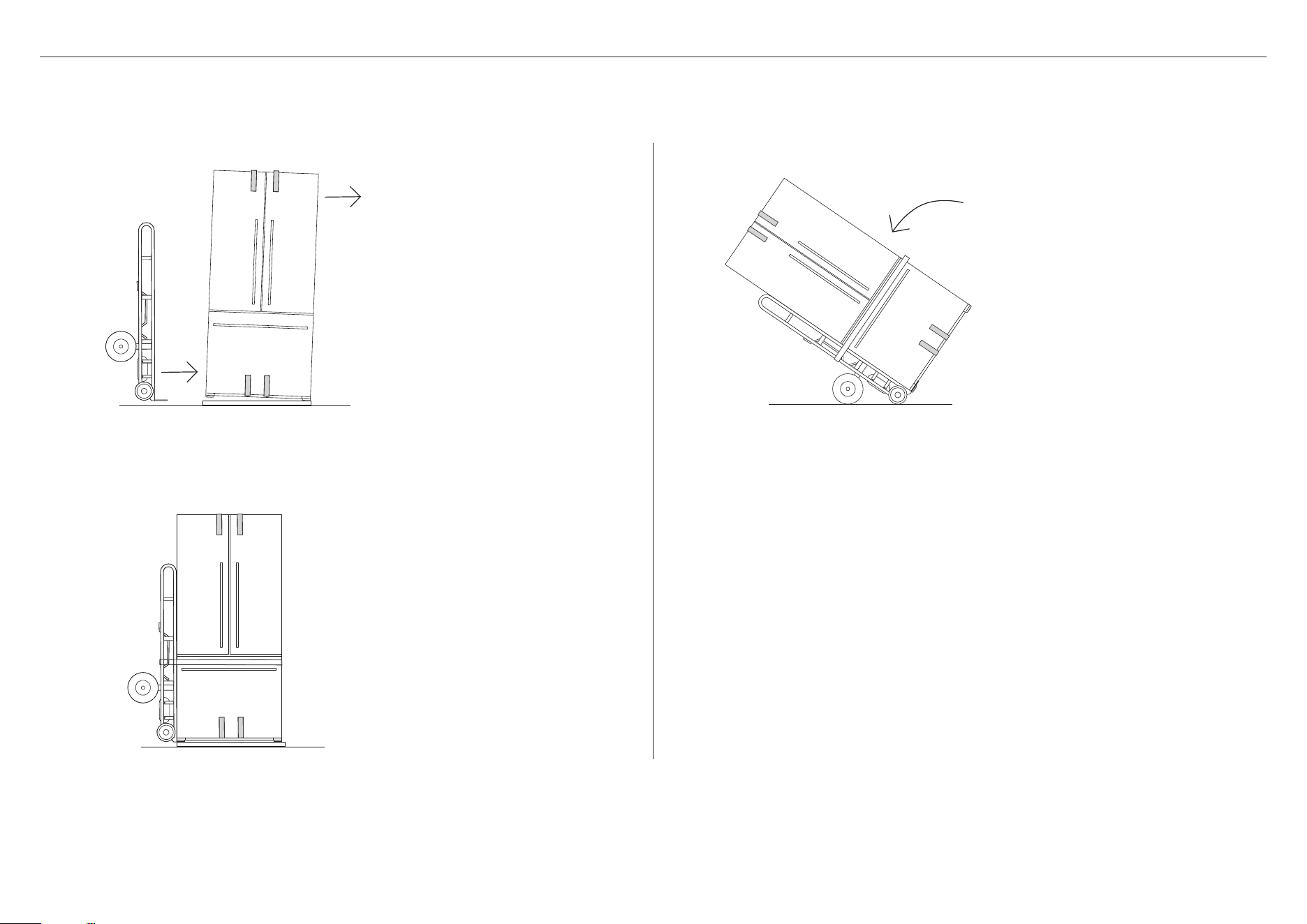
UNPACKING AND MOVING YOUR APPLIANCE
1
2
Check that your appliance is the correct model as per your order.
Follow the steps below to move your appliance to the install location. Be careful when tilting the appliance forward/backward. Tape the door shut to prevent opening while moving the appliance.
Tilt the appliance slightly forward
and Insert the hand truck between
pallet and appliance.
Restrain the appliance with a strap.
3
Tilt backward to load appliance onto
hand truck and push to install location.
14
BEFORE INSTALLATION
Please follow the installation steps below to ensure your appliance operates correctly.
Power
z
Install your appliance where the plug is easily accessible.
z
Connect your refrigerator to a separate power point. Avoid sharing the power point with
other appliances. Do not use extension cords and double adaptors as the combined
weight of two power cords can pull the double adaptor from the power outlet.
z
For power requirements, refer to the information on the serial plate located at the front
bottom right-hand side of the refrigerator when the door is open.
z
Ensure your appliance is properly grounded (earthed).
z
Connect the appliance to the electrical supply (230V, 50Hz) with the fitted plug and
lead.
z
Connections to the mains supply should be in accordance with local regulations.
Ice & Water and Automatic Ice models
z
Your Ice & Water and Automatic Ice refrigerator must be installed by a qualified plumber
or Fisher&Paykel trained and supported service technician as incorrect plumbing can
lead to water leaks.
z
Fisher&Paykel Appliances does not accept responsibility for damage (including water
damage) caused by faulty installation or plumbing.
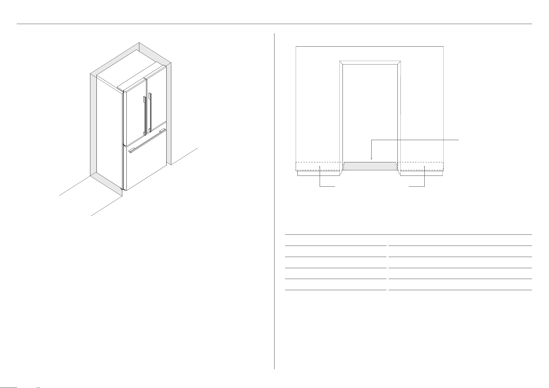
Alternative locations for
connection at rear of cavity
Electrical connection
must be within this space
if located behind the
appliance and must not
protrude from the back wall.
ELECTRICAL SPECIFICATIONS
Supply 230 VAC, 50 Hz
Service 10 amp circuit
Socket 3-pin earthing-type
Total length of power cord 1016mm
We recommend the use of an isolating switch that is easily accessible to the user after the
refrigerator is installed.
water flow
from PRV
water flow to
refrigerator
Inlet
tube
15
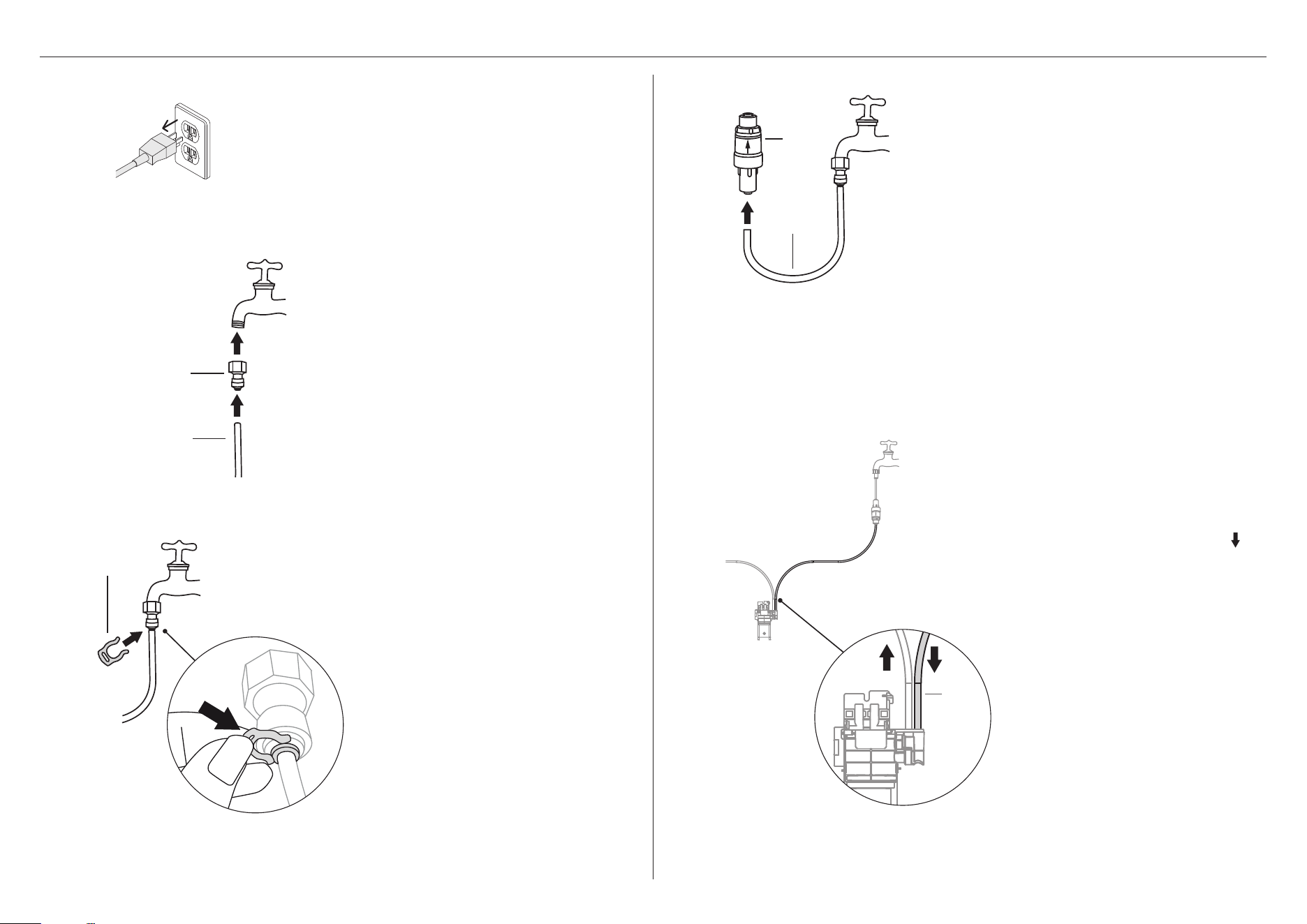
WATER CONNECTION
Ensure the refrigerator is NOT plugged
into a power supply.
Connect the inlet of the PRV to the
tubing connected to the faucet. Ensure
the arrow on the PRV is pointing away
from the faucet. The arrow indicates the
direction of waterflow.
Connect the inlet tube from the filter
head to the PRV. The inlet tube can be
identified by the downward arrow
on
the filter head and a red mark on the
tube.
Ensure the outlet tubing is correctly
connected to the refrigerator water
valve.
Connect the connection fitting to the
faucet.
Connect the short tubing to the outlet
of the faucet and secure with the
locking key.
1
2
3
4
5
connection fitting
short tubing
locking key
PRV
short tubing
16
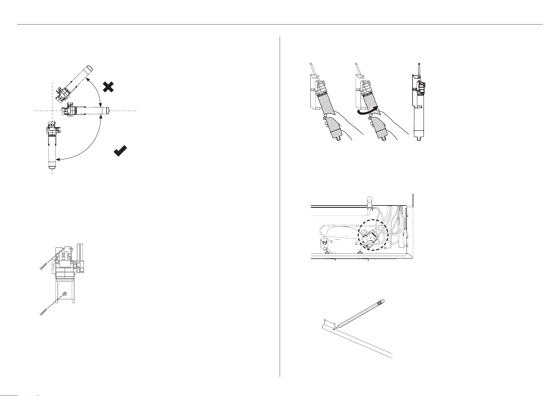
Determine the mounting position for
the water filter noting the following:
z
The water filter MUST not be
mounted with the filter head
position below the base of the filter
(See Diagram 3). We recommend
fitting the water filter in a vertical
orientation with the filter head at the
top. This will minimise water leakage
during replacement of the water
filter.
z
Ensure the water filter is in a
convenient location to access every
6months for replacement. We
recommend that this location is
beside the water filter supply faucet
in a cupboard beside the refrigerator.
z
A minimum clearance of 2” (50mm)
from the bottom of the water filter is
required to perform filter removal.
Attach the wall mounting bracket with
the two screws provided, attach the
bottom screw first then the top screw.
Measure 5/8” (16mm) from one end of
outlet tubing and mark a line.
Run the 1/4” (6mm) tubing to the back
of the refrigerator ensuring there is
enough tubing to pull the refrigerator
out for service.
Insert the filter water into the filter
head. Push the filter firmly into the filter
head and turn in a clockwise direction
until it locks into place.
To flush the water filter of any trapped
air, harmless carbon fines and check for
leaks:
Aim the end of the filter outlet tubing
into a bucket, turn on the faucet and
run 2 gal (8L) of water through. Once
complete, turn the faucet off.
Note: Further flushing is required before
first use of your ice or water functions,
please refer to ‘Before you start using
the Ice & Water or Automatic Ice
function’ fordetails.
6
7
8
9
!0
WATER CONNECTION
0° – 90°
¾” OD x 3/16” ID
Flat Washer
#10-32
Pan Head
Pozi Drive
Wall Plug
#8 x 3/4”
Truss Head
Philips Drive
Self Tapping Screw
¼-20 x ½”
Pan Head
Philips Drive
Machine Screw
M4 x8
Pan Head
Torx Drive
Machine Screw
#10x 3”
Countersunk
Pozidrive
Self tapping Screw
FP Pro Hood Fasteners
¾” OD x 3/16” ID
Flat Washer
#10-32
Pan Head
Pozi Drive
Wall Plug
#8 x 3/4”
Truss Head
Philips Drive
Self Tapping Screw
¼-20 x ½”
Pan Head
Philips Drive
Machine Screw
M4 x8
Pan Head
Torx Drive
Machine Screw
#10x 3”
Countersunk
Pozidrive
Self tapping Screw
FP Pro Hood Fasteners
17
WATER CONNECTION
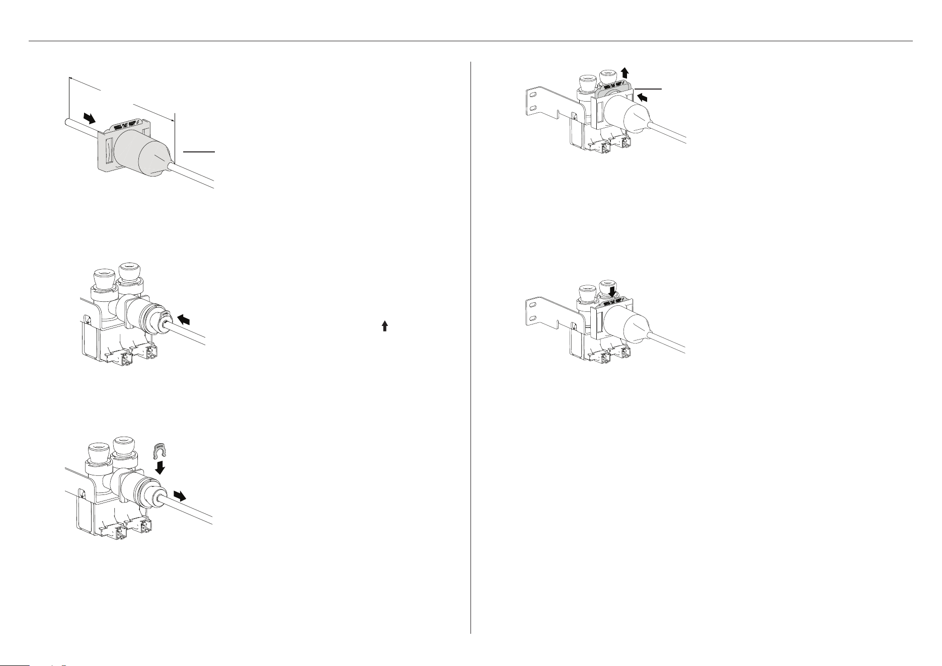
!3
!4
!5
Insert a locking ring and then pull the
outlet tubing gently to ensure it is
locked.
Slide the cover all the way through the
water valve. Pull up the locking piece
and push the cover until it snap-locks
into the valve.
Check if the cover is aligned correctly.
Press the locking piece down to lock
the cover in place.
Turn the faucet on and check that all
connections are dry and free of drips.
Coil water line tubing behind the
refrigerator. Pushyour refrigerator
into place being careful notto kink or
squash the water line tube.
Turn refrigeratoron.
locking piece
Insert the outlet tubing to water
(solenoid) valve up to the marked line.
z
The outlet tubing can be identified
by the upward arrow on the filter
head and a blue mark on the tube.
!2
Insert one end of the outlet tubing into
the tube bore of the water valve cover
and slide back about 1 3/16” (30mm).
!1
valve cover
1 3/16” (30mm)
18
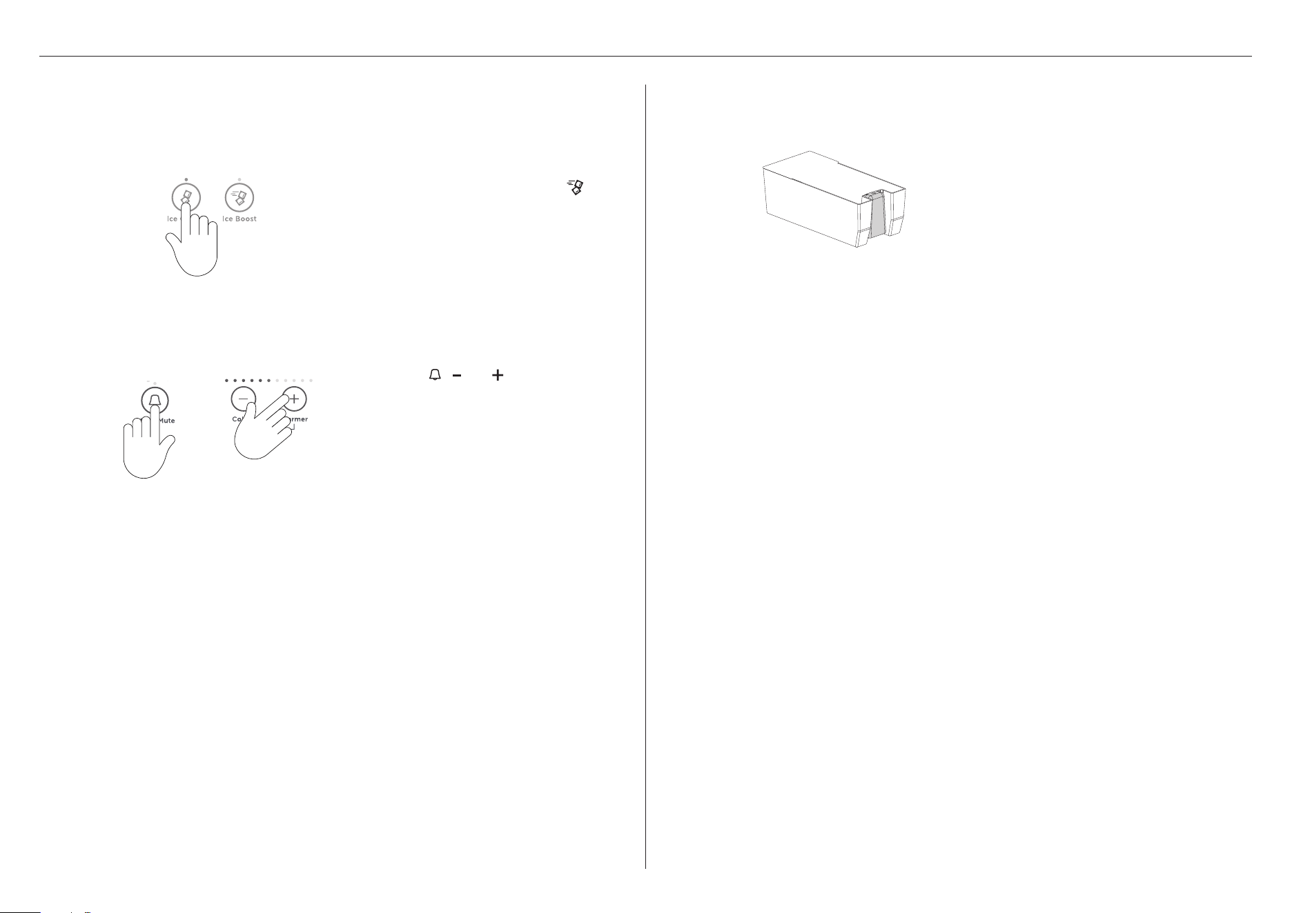
Empty the water, dry the bin and return
it correctly.
Once your ice maker is turned on the first bin of ice may be discoloured. This is not harmful
and normal during the flushing process. Discard the first full bin of ice made. Your ice maker is
now ready for use.
The performance of your water filter will increase with use, reaching optimum performance
after two to three full bins of ice.
Carry out the above steps after a holiday/vacation or extended periods of not using ice.
3
Automatic ice function
To turn your ice maker on press
.
The light above the button will illuminate.
Press the
, and together for 4
seconds then close the doors. The ice
tray will empty the water into the bin
below. The ice tray will only empty after
the doors are closed.
Repeat to remove dust in the ice tray
collected during manufacture and
transport.
1
2
FLUSHING THE WATER FILTER
19
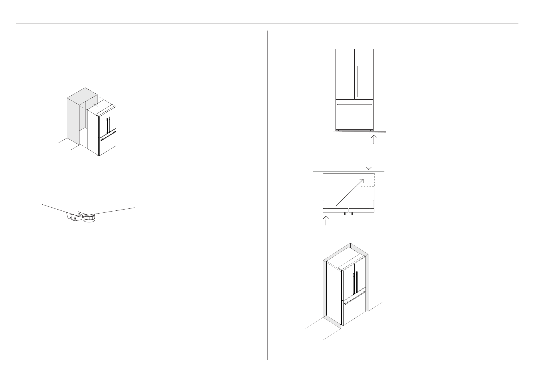
POSITIONING YOUR REFRIGERATOR
1
2
Your Fisher&Paykel ActiveSmart™ refrigerator is fitted with front and rear rollers to allow you
to easily move your refrigerator forward and backward.
Avoid moving your refrigerator sideways to prevent damaging the rollers or the floor
coveringsurface.
Your refrigerator will arrive with the front feet wound up to assist with moving the product
into its final location.
Roll the refrigerator into its final
position ensuring there is the correct
air gap between the product and
surrounding cabinetry. See minimum
clearance in cabinetry dimensions table.
Adjust the front feet down until the
refrigerator is leaning backward with
the front approximately 3/8" 10mm
higher than the back. This will ensure
a good door closing action.
What to do if your product is unstable
Gently push the refrigerator back until
the rear rollers contact the floor.
Measure the gap under the front foot,
which has come off the floor.
Obtain some solid packing material
(hardwood, plastic,etc) which fits firmly
into the gap under the foot.
1
2
3
Wind both front feet up and roll the
product out ofposition.
Place the packing material in the
location diagonally opposite the front
roller that lifts off the floor.
Ensure the packing material stays in
place when the product is pushed back
into position.
Roll the refrigerator back into position
and adjust front feet. Check alignment
and door closing action are satifactory.
Make small adjustments to the front feet
where necessary.

20
COMPLETE INSTALLATION
Before placing food in the fresh food or freezer compartments
z
Remove all internal packaging. Ensure that all transit clips are removed from the refrigerator.
These are small rubber stoppers located at the back of the shelves.
z
Clean the inside of the appliance with a mix of warm water and a small amount of liquid
detergent. Use a soft cloth to remove dust collected during manufacture and transport.
z
Allow the refrigerator and freezer to run empty for 2 – 3 hours to allow each compartment
to cool to the appropriate temperature.
z
The appliance may have an odor on its initial operation, this will go when the refrigerator
and freezer have cooled sufficiently.
Energy efficiency
For the most energy efficient use of your appliance:
z
Ensure your refrigerator has adequate ventilation.
z
Do not cover your appliance with any material that will prevent air from flowing aroundthe
cabinet sides.
z
Ensure you vacuum around the appliance to remove dust and accumulated debris.
Keepthe appliance and its cabinetry free of dust by wiping down with a dry, lint-free cloth
(refer to section ‘Cleaning and caring for your refrigerator’).
z
Allow good clearances in front of air ducts within the cabinet for maximum
cold airdistribution.
z
Cool down hot foods before placing them in the appliance.
z
Do not overfill the compartments.
z
Keep door openings to a minimum.
z
Select a temperature setting that isn’t too cold.
z
Check your door seals for leaks.

21
FINAL CHECKLIST
TO BE COMPLETED BY THE INSTALLER
Check all parts are installed.
Ensure the appliance is level.
Ensure all internal and external packaging is removed from the appliance before use.
Ensure the water filter is installed and the has been flushed.
Complete and keep for safe reference:
Model
Serial No.
Purchase Date
Purchaser
Dealer Address
Installer’s Name
Installer’s Signature
Installation Company
Installation Date

867220E 03.25
FISHERPAYKEL.COM
© Fisher & Paykel Appliances 2025. All rights reserved.
The models shown in this guide may not be available in all markets
and are subject to change at any time.
The product specifications in this guide apply to the specific products and
models described at the date of issue. Under our policy of continuous product
improvement, these specifications may change at any time.
For current details about model and specification availability in your country,
please go to our website or contact your local Fisher&Paykel dealer.

